EP3206035A1 - Automatic analysis system - Google Patents
Automatic analysis system Download PDFInfo
- Publication number
- EP3206035A1 EP3206035A1 EP14905750.7A EP14905750A EP3206035A1 EP 3206035 A1 EP3206035 A1 EP 3206035A1 EP 14905750 A EP14905750 A EP 14905750A EP 3206035 A1 EP3206035 A1 EP 3206035A1
- Authority
- EP
- European Patent Office
- Prior art keywords
- analysis
- automatic analysis
- specimen
- section
- automatic
- Prior art date
- Legal status (The legal status is an assumption and is not a legal conclusion. Google has not performed a legal analysis and makes no representation as to the accuracy of the status listed.)
- Granted
Links
Images



Classifications
-
- G—PHYSICS
- G01—MEASURING; TESTING
- G01N—INVESTIGATING OR ANALYSING MATERIALS BY DETERMINING THEIR CHEMICAL OR PHYSICAL PROPERTIES
- G01N35/00—Automatic analysis not limited to methods or materials provided for in any single one of groups G01N1/00 - G01N33/00; Handling materials therefor
- G01N35/02—Automatic analysis not limited to methods or materials provided for in any single one of groups G01N1/00 - G01N33/00; Handling materials therefor using a plurality of sample containers moved by a conveyor system past one or more treatment or analysis stations
- G01N35/04—Details of the conveyor system
-
- G—PHYSICS
- G01—MEASURING; TESTING
- G01N—INVESTIGATING OR ANALYSING MATERIALS BY DETERMINING THEIR CHEMICAL OR PHYSICAL PROPERTIES
- G01N35/00—Automatic analysis not limited to methods or materials provided for in any single one of groups G01N1/00 - G01N33/00; Handling materials therefor
- G01N35/00584—Control arrangements for automatic analysers
- G01N35/0092—Scheduling
-
- G—PHYSICS
- G01—MEASURING; TESTING
- G01N—INVESTIGATING OR ANALYSING MATERIALS BY DETERMINING THEIR CHEMICAL OR PHYSICAL PROPERTIES
- G01N35/00—Automatic analysis not limited to methods or materials provided for in any single one of groups G01N1/00 - G01N33/00; Handling materials therefor
- G01N2035/00178—Special arrangements of analysers
- G01N2035/00326—Analysers with modular structure
-
- G—PHYSICS
- G01—MEASURING; TESTING
- G01N—INVESTIGATING OR ANALYSING MATERIALS BY DETERMINING THEIR CHEMICAL OR PHYSICAL PROPERTIES
- G01N35/00—Automatic analysis not limited to methods or materials provided for in any single one of groups G01N1/00 - G01N33/00; Handling materials therefor
- G01N35/00584—Control arrangements for automatic analysers
- G01N35/00722—Communications; Identification
- G01N35/00732—Identification of carriers, materials or components in automatic analysers
- G01N2035/00742—Type of codes
- G01N2035/00752—Type of codes bar codes
-
- G—PHYSICS
- G01—MEASURING; TESTING
- G01N—INVESTIGATING OR ANALYSING MATERIALS BY DETERMINING THEIR CHEMICAL OR PHYSICAL PROPERTIES
- G01N35/00—Automatic analysis not limited to methods or materials provided for in any single one of groups G01N1/00 - G01N33/00; Handling materials therefor
- G01N35/00584—Control arrangements for automatic analysers
- G01N35/00722—Communications; Identification
- G01N2035/00891—Displaying information to the operator
- G01N2035/0091—GUI [graphical user interfaces]
-
- G—PHYSICS
- G01—MEASURING; TESTING
- G01N—INVESTIGATING OR ANALYSING MATERIALS BY DETERMINING THEIR CHEMICAL OR PHYSICAL PROPERTIES
- G01N35/00—Automatic analysis not limited to methods or materials provided for in any single one of groups G01N1/00 - G01N33/00; Handling materials therefor
- G01N35/02—Automatic analysis not limited to methods or materials provided for in any single one of groups G01N1/00 - G01N33/00; Handling materials therefor using a plurality of sample containers moved by a conveyor system past one or more treatment or analysis stations
- G01N35/04—Details of the conveyor system
- G01N2035/0401—Sample carriers, cuvettes or reaction vessels
- G01N2035/0412—Block or rack elements with a single row of samples
- G01N2035/0413—Block or rack elements with a single row of samples moving in one dimension
-
- G—PHYSICS
- G01—MEASURING; TESTING
- G01N—INVESTIGATING OR ANALYSING MATERIALS BY DETERMINING THEIR CHEMICAL OR PHYSICAL PROPERTIES
- G01N35/00—Automatic analysis not limited to methods or materials provided for in any single one of groups G01N1/00 - G01N33/00; Handling materials therefor
- G01N35/02—Automatic analysis not limited to methods or materials provided for in any single one of groups G01N1/00 - G01N33/00; Handling materials therefor using a plurality of sample containers moved by a conveyor system past one or more treatment or analysis stations
- G01N35/04—Details of the conveyor system
- G01N2035/0439—Rotary sample carriers, i.e. carousels
- G01N2035/0441—Rotary sample carriers, i.e. carousels for samples
-
- G—PHYSICS
- G01—MEASURING; TESTING
- G01N—INVESTIGATING OR ANALYSING MATERIALS BY DETERMINING THEIR CHEMICAL OR PHYSICAL PROPERTIES
- G01N35/00—Automatic analysis not limited to methods or materials provided for in any single one of groups G01N1/00 - G01N33/00; Handling materials therefor
- G01N35/02—Automatic analysis not limited to methods or materials provided for in any single one of groups G01N1/00 - G01N33/00; Handling materials therefor using a plurality of sample containers moved by a conveyor system past one or more treatment or analysis stations
- G01N35/04—Details of the conveyor system
- G01N2035/046—General conveyor features
- G01N2035/0465—Loading or unloading the conveyor
Definitions
- the present invention relates to an automatic analysis system configured by coupling a plurality of automatic analysis devices.
- An automatic analysis device is configured to automatically sample a specimen contained in a container, and to perform analysis.
- Such an automatic analysis device may include, as mechanisms for conveying a specimen, mechanisms such as a conveyor belt for conveying a specimen rack holding a plurality of specimen containers and placed on the conveyor belt, an arm for pulling the specimen rack conveyed to a predetermined position by the conveyor belt from the conveyor belt into the device, and the like (for example, see Patent Document 1).
- Such an automatic analysis device includes, at a beginning side of the conveyor belt, an installation section where a specimen rack is to be installed by an operator, and includes, at an end side, a specimen rack recovery section for recovering a specimen rack for which sampling has been completed.
- an operator installs a specimen rack on the installation section
- the specimen rack is conveyed by the conveyor belt and is pulled into the device at a predetermined position by the arm, and sampling of a specimen is performed.
- the specimen rack for which sampling is completed is returned by the arm onto the conveyor belt, and is conveyed by the conveyor belt to the specimen rack recovery section at the end side and is recovered.
- one automatic analysis device Because there is a limit on the number of analysis items that can be processed by one automatic analysis device, if there are a large number of specimens to be analyzed, it takes a long time to analyze all the specimens. Further, in the case where a plurality of analysis items have to be performed on one specimen, one automatic analysis device may not be able to perform all the analysis items. In such a case, a specimen container containing the specimen is installed in one automatic analysis device and sampling is performed by the automatic analysis device, and then, an operator has to remove the specimen rack for which sampling has been completed from a recovery section of the automatic analysis device and to install the specimen rack in another automatic analysis device.
- one automatic analysis system is constructed by a plurality of automatic analysis devices, depending on the number of specimens to be analyzed or an analysis schedule, a plurality of automatic analysis devices are preferably operated so as to process a plurality of specimens simultaneously in parallel to thereby increase the analysis efficiency, or one automatic analysis device is preferably operated alone while stopping other automatic analysis devices.
- management information about which reagent is installed at which position in which device and which analysis item can be performed is different between a case where a plurality of automatic analysis devices are to be operated at the same time and a case where only one of the automatic analysis devices is to be operated, and the management information has to be acquired and reset at the time of switching between a state where a plurality of automatic analysis devices are to be operated and a state where one automatic analysis device is to be operated alone, and time is thus required.
- the present invention has its object to enable, with respect to an automatic analysis device where a plurality of automatic analysis devices are coupled, swift switching between a state where analyses are to be performed by operating a plurality of automatic analysis devices and a state where an analysis is to be performed by operating one automatic analysis device.
- a mode of an automatic analysis system includes an analysis device group including a plurality of automatic analysis devices, a specimen transport device, mode switching means, an assignment information holding section, analysis item setting means, and analysis item execution means.
- Each automatic analysis device constituting the analysis device group includes a conveying section for conveying a specimen container containing a specimen, a reagent table on which a plurality of reagent containers containing reagents are to be installed, an analysis operation section for collecting a specimen from a specimen container conveyed by the conveying section to a predetermined position, and for performing analysis by adding a reagent, among reagents installed on the reagent table, to the specimen, a power supply device for supplying necessary power to the conveying section and the analysis operation section, and an analysis control section for controlling operation of the conveying section and the analysis operation section.
- the specimen transport device couples two automatic analysis devices that are adjacent to each other, and transports a specimen container between the automatic analysis devices.
- the mode switching means selects, and switches to, one of a multi-operation mode in which a plurality of automatic analysis devices that are coupled to each other by the specimen transport device are placed in an operation state and a single operation mode in which only one automatic analysis device is placed in the operation state.
- the assignment information holding section holds analysis item assignment information assigned in advance to each automatic analysis device as an analysis item to be performed by each automatic analysis device in the analysis device group in each of the multi-operation mode and the single operation mode.
- the analysis item setting means sets, in each of the modes, an analysis item, among analysis items assigned to each automatic analysis device, as an analysis item to be performed on an analysis target specimen, based on the analysis item assignment information held in the assignment information holding section.
- the analysis item execution means supplies information about the analysis item set by the analysis item setting means to the analysis control section of each automatic analysis device, and causes the analysis item to be performed on a specimen on which the analysis item is to be performed.
- the automatic analysis system includes the analysis device group including a plurality of automatic analysis devices, and each automatic analysis device in the analysis device group includes the conveying section, the reagent table, the analysis operation section, the power supply device, and the analysis control section, and thus, each automatic analysis device may be operated alone to perform analysis of a specimen.
- the mode switching means for selecting, and switching to, one of the multi-operation mode in which a plurality of automatic analysis devices are operated at the same time and the single operation mode in which only a specific automatic analysis device is operated, and an analysis item, among a plurality of analysis items assigned to each automatic analysis device, is performed in each mode on an analysis target specimen based on the analysis item assignment information set in advance, and thus, switching between the multi-operation mode and the single operation mode may be easily and swiftly performed.
- a reagent which is common with a reagent installed on a reagent table of another automatic analysis device is installed on the reagent table of one automatic analysis device which is to be operated in a single operation mode, and an analysis item which uses the common reagent is preferably assigned to the other automatic analysis device in a multi-operation mode, and to the one automatic analysis device in the single operation mode.
- a system control section that is electrically connected to an analysis control section of each automatic analysis device, and that manages operation of each automatic analysis device is further provided, and mode selection means, an assignment information holding section, analysis item setting means, and analysis item execution means are provided to the system control section. According to such a mode, all the automatic analysis devices may be integrally managed by the system control section, and management of the automatic analysis system by an operator is facilitated.
- An information display section that is electrically connected to the system control section, and that displays information output from the system control section is further provided, and the mode switching means displays, on the information display section, a mode selection screen urging an operator to select one of the multi-operation mode and the single operation mode, and causes the operator to select one of the multi-operation mode and the single operation mode on the mode selection screen.
- An operator may thereby perform switching between the multi-operation mode and the single operation mode on a display screen of the information display section, and switching of the modes is facilitated.
- the analysis control section of each automatic analysis device also controls supply of power from a power supply device to a conveyor belt and an analysis operation section
- the system control section further includes non-operating device suspending means for supplying a signal for placing an automatic analysis device, other than an automatic analysis device that is to be placed in an operation state, in a suspended state in which supply of power from the power supply device to the conveying section and the analysis operation section is cut off, to the analysis control section of a corresponding automatic analysis device.
- An automatic analysis device which is not scheduled to be operated is thereby automatically placed in the suspended state, and wasteful consumption of power and the like may be proposed.
- the conveying section provided to each automatic analysis device is a conveyor belt that includes a beginning and an end, and that conveys a specimen container in one direction from a beginning side to an end side, and two automatic analysis devices that are adjacent to each other are arranged in such a way that the end of the conveyor belt of one automatic analysis device is close to and faces the beginning of the conveyor belt provided to the other automatic analysis device, and a specimen transport device includes a transport mechanism that is arranged between the conveyor belts of the two automatic analysis devices that are adjacent to each other, and that holds a specimen container which reached the end of one conveyor belt and transports the specimen container to the beginning of the other conveyor belt.
- the size of the entire analysis system may be reduced.
- FIG. 1 and 2 show two automatic analysis devices constituting the automatic analysis system, and a specimen transport device coupling the automatic analysis devices. A control device for managing the operation of these devices will be described later.
- An automatic analysis system 1 is configured by an analysis device group including two automatic analysis devices 2a, 2b, a specimen transport device 12, and a control device 34 (see Fig. 3 ) connected to these devices 2a, 2b, 12.
- the two automatic analysis devices 2a, 2b constituting the analysis device group are arranged next to each other in an X-direction, which is one direction on a horizontal plane, and conveying sections 6a and 6b of the respective automatic analysis devices 2a, 2b are coupled to each other by the specimen transport device 12.
- the analysis device group is configured by the two automatic analysis devices 2a and 2b, the analysis device group may alternatively be configured by three or more automatic analysis devices. In the case of configuring the analysis device group by coupling n (n ⁇ 3) automatic analysis devices in series, n-1 specimen transport devices 12 become necessary.
- the automatic analysis device 2a includes an analysis operation section 4a, a conveying section 6a, and a specimen introduction mechanism 18a.
- the automatic analysis device 2b likewise includes an analysis operation section 4a, a conveying section 6a, and a specimen introduction mechanism 18a.
- the automatic analysis device 2a and the automatic analysis device 2b include respective power supply devices 33a, 33b (see Fig. 3 ), and an operator may turn on/off power of each device 2a, 2b by a power switch 15a, 15b.
- the automatic analysis devices 2a and 2b may operate independently of each other, and even if power of one of the automatic analysis devices is turned off, analysis operation may be performed by the other automatic analysis device.
- the automatic analysis devices 2a and 2b are devices having the same configuration.
- the configuration of the automatic analysis device 2a will be described.
- the conveying section 6a includes a conveyor belt 7a for conveying a specimen rack 20 holding a specimen container in one direction in the X-direction (the direction of right to left in Figs. 1 and 2 ) .
- the surrounding portion of the conveyor belt 7a is covered by a cover.
- a specimen rack placement section 8a is provided on the beginning side of the conveying section 6a (the right side in Figs. 1 and 2 ), and a specimen rack recovery section 10a is provided on the end side (the left side in the drawings).
- Covers of the specimen rack placement section 8a and the specimen rack recovery section 10a can be opened/closed, and an operator may open the cover of the specimen rack placement section 8a and arrange a specimen rack on the conveyor belt 7a, or may open the cover of the specimen rack recovery section 10a and take out a specimen rack for which sampling is completed.
- the specimen introduction mechanism 18a moves in a Y-direction orthogonal to the X-direction on the horizontal plane, and holds a specimen rack 20 on the conveyor belt 7a and introduces the specimen rack 20 to the side of the analysis operation section 4a, or returns a specimen rack 20 for which sampling has been completed onto the conveyor belt 7a.
- a specimen rack introduction section 9a is provided between the specimen rack placement section 8a and the specimen rack recovery section 10a of the conveying section 6a.
- a stopper for stopping a specimen rack 20 conveyed by the conveyor belt 7a and for releasing the stopped specimen rack 20 is provided to the specimen rack introduction section 9a.
- the specimen introduction mechanism 18a holds the specimen rack 20 stopped at a predetermined position by the stopper, and transfers the specimen rack 20 into the analysis operation section 4a. Further, the specimen introduction mechanism 18 returns, at the specimen rack introduction section 9a, onto the conveyor belt 7a, a specimen rack 20 in which the processing at the analysis operation section 4a is completed.
- the analysis operation section 4a includes, in addition to a specimen collection mechanism (not shown) including, for example, a suction probe for collecting a specimen from a specimen container transferred by the specimen introduction mechanism 18a, a reagent installation section 22a, a specimen rack housing section 24a, and a measurement section 26a.
- a specimen collection mechanism including, for example, a suction probe for collecting a specimen from a specimen container transferred by the specimen introduction mechanism 18a, a reagent installation section 22a, a specimen rack housing section 24a, and a measurement section 26a.
- a plurality of specimen racks 20 transferred from the conveyor belt 7a by the specimen introduction mechanism 18a are housed in the specimen rack housing section 24a.
- the specimen rack housing section 24a is a turntable, and places a specimen container on a specimen rack 20 at a predetermined position where a specimen is collected by the suction probe.
- a plurality of reagent holders 23a for installing reagent containers containing reagents are provided to the reagent installation section 22a.
- Reagent information about a reagent container installed in each reagent holder 23a of the reagent installation section 22a is input to the control device 34 (see Fig. 3 ) by an operator inputting the reagent information about an installed reagent container to the control device 34 or by a bar code reader, as an information reader, reading information of a bar code which is an information medium attached to each reagent container, and what reagent is contained in which reagent holder 23a is registered in the control device 34.
- a plurality of containers for mixing a specimen collected by the suction probe and a reagent are provided at the measurement section 26a, and reaction in a container is optically measured.
- a specimen rack 20 is housed in the specimen rack housing section 24a by the specimen introduction mechanism 18a, a specimen container held by the specimen rack 20 is placed at a predetermined position, and a specimen is collected by the suction probe.
- the collected specimen is injected into a container provided at the measurement section 26a, and after a reagent according to an analysis item is added by the suction probe, reaction between the specimen and the reagent is optically measured in terms of absorbance, fluorescence intensity, or the like.
- the conveyor belt 7b of the automatic analysis device 2b is arranged on the same straight line as the conveyor belt 7a of the automatic analysis device 2a, and the beginning of the conveyor belt 7b is arranged facing the end of the conveyor belt 7a.
- the specimen transport device 12 is arranged between the conveyor belts 7a and 7b, and couples the conveyor belts 7a and 7b.
- the specimen transport device 12 includes a transport mechanism 100 (see Figs. 6 to 8 ) for holding a specimen rack 20 which reached the end of the conveyor belt 7a and for placing the specimen rack 20 on the beginning of the conveyor belt 7b, and the transport mechanism is covered by an openable shielding cover 14.
- the specimen transport device 12 includes a first sensor 110 for detecting a specimen rack 20 which reached the end of the conveyor belt 7a, and a second sensor 112 for detecting a specimen rack 20 which reached the beginning of the conveyor belt 7b (see Figs. 6 to 8 ) . When a specimen rack 20 is determined by the first sensor to have reached the end of the conveyor belt 7a, the specimen transport device 12 automatically starts transporting the specimen rack 20.
- the automatic analysis device 2a includes an analysis control section 32a for controlling the operation and managing the states of the analysis operation section 4a, the conveyor belt 7a, and the specimen introduction mechanism 18a, and a power supply device 33a for supplying necessary power to each part mentioned above.
- the power supply device 33a is provided with a power switch 15a, and switching between on and off of supply of power to the analysis operation section 4a, the conveyor belt 7a, the specimen introduction mechanism 18a, and the analysis control section 32a is performed by the power switch 15a.
- the automatic analysis device 2b includes an analysis control section 32b for controlling the operation and managing the states of the analysis operation section 4b, the conveyor belt 7b, and the specimen introduction mechanism 18b, and a power supply device 33b for supplying necessary power to each part mentioned above.
- the power supply device 33b is provided with a power switch 15a, and switching between on and off of supply of power to the analysis operation section 4b, the conveyor belt 7b, the specimen introduction mechanism 18b, and the analysis control section 32b is performed by the power switch 15b.
- the specimen transport device 12 includes the transport mechanism 100 for transporting a specimen rack, the first sensor 110 for detecting a specimen rack 20 which reached the end of the conveyor belt 7a, the second sensor 112 for detecting a specimen rack 20 which reached the beginning of the conveyor belt 7b, and a transport control section 101 for controlling the operation of the transport mechanism 100. Detection signals of the first sensor 110 and the second sensor 112 are captured by the control device 34 via the transport control section 101, and the transport state of a specimen rack 20 at the specimen transport device 12 is managed by the control device 34.
- the analysis control sections 32a, 32b and the transport control section 101 are connected to the control device 34 by communication cables, and communication of information to/from the control device 34 is thereby performed.
- the control device 34 is a system control section for managing and controlling the entire automatic analysis system.
- the control device 34 may be realized by a computer dedicated to the automatic analysis system, or by a general-purpose personal computer.
- the control device 34 includes analysis item assignment means 35, analysis item display means 36, analysis item setting means 37, analysis item execution means 38, mode switching means 39, an assignment information holding section 40, and a non-operating device suspending means 42.
- the analysis item assignment means 35 allows an operator to perform setting regarding assignment of analysis items to be performed at each automatic analysis device 2a, 2b, or automatically performs setting based on information input from outside (for example, information recorded in a recording medium). Normally, mutually different analysis items are assigned to the automatic analysis devices 2a, 2b assuming that the analysis devices are to be operated at the same time so that throughput is increased with respect to analysis of a plurality of specimens. Accordingly, a reagent to be used for an analysis item to be performed at respective one of the automatic analysis devices 2a, 2b is installed in the reagent installation section 22a, 22b.
- the multi-operation mode is a mode in which analyses are performed by operating both of the automatic analysis devices 2a, 2b
- the single operation mode is a mode in which an analysis is performed by operating one of the automatic analysis devices 2a, 2b.
- An operator is allowed to select one of the modes according to the number of specimens to be analyzed and the types thereof.
- the single operation mode only one automatic analysis device is operated, and thus, the one automatic analysis device 2a or 2b is preferably able to perform a large number of analysis items (i.e. analysis items for two devices).
- a reagent which is common with a reagent installed in the other automatic analysis device 2b or 2a has to be installed in the one automatic analysis device 2a or 2b which is to be operated in the single operation mode, and two types of analysis items for the multi-operation mode and the single operation mode have to be assigned to the automatic analysis device 2a or 2b which is to be operated in the single operation mode.
- the analysis item assignment means 35 assigns analysis items to each automatic analysis device 2a, 2b for a case of the multi-operation mode and for a case of the single operation mode. Information about assignment of analysis items performed by the analysis item assignment means 35 is held in the assignment information holding section 40 as assignment information.
- the mode switching means 39 is provided for switching between the operation modes.
- the mode switching means 39 displays a mode selection screen on an information display section 44, and causes the operator to select one of the multi-operation mode and the single operation mode on the information display section 44.
- a specimen which is introduced into the automatic analysis system is identified by reading a bar code attached to the specimen container, for example, and is managed in association with an analysis item which is to be performed on the specimen.
- the control device 34 controls the operation of the conveyor belt 7a, 7b and the transport mechanism 100 through the analysis control section 32a, 32b and the transport control section 101 in such a way that each specimen is introduced into the automatic analysis device 2a or 2b which is to perform a respective analysis item that is set.
- the analysis item display means 36 displays, on the information display section 44, an analysis item that can be performed.
- the information display section 44 is, for example, a touch panel liquid crystal display device.
- the analysis item setting means 37 sets an analysis item selected by the operator from the analysis items displayed on the information display section 44 as an analysis item to be performed on a target specimen.
- the analysis item execution means 38 transmits information about the analysis item set by the analysis item setting means 37 to the automatic analysis device 2a or 2b for handling the analysis item so as to cause the analysis item to be performed.
- the operator causes analysis items which can be performed to be displayed on the information display section 44, and selects, on the information display section 44, an analysis item to be performed from the displayed analysis items.
- information about the analysis item and information about the installed specimen container are associated with each other, and are transmitted from the control device 34 to the automatic analysis device 2a, 2b.
- the automatic analysis device 2a, 2b performs the selected analysis item on the target specimen based on the pieces of information from the control device 34.
- the non-operating device suspending means 42 transmits a signal, for achieving a suspended state, to an automatic analysis device which is not to be operated, and places the automatic analysis device in the suspended state.
- the suspended state is, for example, a state in which supply of power to a module other than modules which should be operated at all times is stopped.
- Modules which should be operated at all times include temperature adjustment elements, such as Peltier devices of the reagent installation sections 22a, 22b, which are necessary for keeping reagents at constant temperature, for example.
- the power consumption of an automatic analysis device which is placed in the suspended state is minimized, and also, consumption of cleaning liquid or ion exchange water which is constantly consumed in an operation state is suppressed.
- the non-operating device suspending means 42 may stop supply of power to the transport mechanism 100, the first sensor 110, and the second sensor 112 of the specimen transport device 12 when the operation mode is switched to the single operation mode.
- the power consumption at the time of the single operation mode may thereby be further reduced.
- the automatic analysis device 2a analysis device 1 and the automatic analysis device 2b (analysis device 2) are started, and reagent containers are installed in the reagent installation sections 22a, 22b of the respective analysis devices.
- An identifier (such as a bar code) including unique information is attached to the bottom surface of each reagent container, for example, and a reagent map is created when the identifier is read by a reader, such as a bar code reader, provided to each automatic analysis device 2a, 2b, and what reagent is installed in which of the reagent holding sections 23a, 23b of the reagent installation sections 22a, 22b is recognized by each automatic analysis device 2a, 2b and the control device 34.
- a reader such as a bar code reader
- an analysis item is assigned to each automatic analysis device 2a, 2b for a case of the multi-operation mode and for a case of the single operation mode.
- Information of the analysis item assigned to each automatic analysis device 2a, 2b is held in the assignment information holding section 40 as assignment information.
- the analysis items A, B, C, D, E, and F are assigned to the automatic analysis device 2a, and the analysis items D, E, and F are assigned to the automatic analysis device 2b.
- the analysis items A, B, C, D, E, and F are assigned to the automatic analysis device 2a, and the analysis items D, E, and F are assigned to the automatic analysis device 2b.
- reagents to be used for the analysis items A, B, C, D, E, and F all have to be installed in the reagent installation section 22a of the automatic analysis device 2a.
- the reagents for the analysis items D, E, and F installed in the reagent installation section 22a of the automatic analysis device 2a are used only in the single operation mode, and are not used in the multi-operation mode. Additionally, all the reagents for the analysis items A, B, C, D, E, and F may also be installed in the reagent installation section 22b of the automatic analysis device 2b, and A, B, C, D, E, and F may also be assigned to the automatic analysis device 2b as the analysis items for the time of the single operation mode. This allows all the analysis items to be performed in the single operation mode regardless of which of the automatic analysis devices 2a, 2b is in the operation state.
- the mode switching means 39 causes the information display section 44 to display the mode selection screen, and causes the operator to select an operation mode.
- analysis items to be performed are assigned to the automatic analysis devices 2a, 2b based on the assignment information held in the assignment information holding section 40. Then, when the operator installs a specimen and selects an analysis item to be performed on the specimen, the specimen is introduced into the automatic analysis device 2a or 2b to which the selected analysis item is assigned, and the analysis item is performed on the specimen.
- a screen for allowing the operator to select the automatic analysis device 2a or 2b to be operated alone is displayed by the information display section 44, and one of the automatic analysis devices 2a, 2b to be operated is selected.
- an analysis item is assigned to the selected automatic analysis device 2a or 2b based on the assignment information held in the assignment information holding section 40.
- the non-operating device suspending means 42 transmits a signal for placing the other automatic analysis device 2b or 2a which was not selected by the operator in the suspended state to the corresponding automatic analysis device 2b or 2a. Then, when the operator installs a specimen in the automatic analysis device 2a or 2b which is to be operated alone, and selects an analysis item to be performed on the specimen, the selected analysis item is performed by the automatic analysis device 2a or 2b which is operated alone.
- the same automatic analysis device may be constantly set as the automatic analysis device to be operated alone in the single operation mode.
- the mode switching means 39 checks the current operation mode, and if the current operation mode is the multi-operation mode, selection of the automatic analysis device to be operated alone, setting of a reagent map to be used, extraction and setting of analysis items that can be performed, and placement of the automatic analysis device which is not to be operated in the suspended state are performed, and analysis in the single operation mode is started.
- the current operation mode is the single operation mode
- a suspended automatic analysis device is restored to the operation state, and creation of a reagent map for the multi-operation mode, extraction of analysis items that can be performed, and setting of the automatic analysis devices which are to perform respective analysis items are performed, and analysis in the multi-operation mode is started.
- the information display section 44 preferably performs display urging the operator to turn on the corresponding automatic analysis device.
- the transport mechanism 100 includes a table 102 having a horizontal plane.
- the table 102 is supported by a base 118.
- the horizontal plane of the table 102 is set to approximately the same height as the conveyance surfaces of the conveyor belts 7a, 7b arranged on both ends.
- the position near an end portion on one side of the table 102 in the X-direction (the right side in the drawing) is a conveyance start position 103a where conveyance of a specimen rack is started, and the end of the conveyor belt 7a on the former stage is arranged at the conveyance start position 103a.
- the position near an end on the other side of the table 102 in the X-direction is a conveyance end position 103b for a specimen rack, and the beginning of the conveyor belt 7b on the latter stage is arranged at the conveyance end position 103b.
- An arm member 104 and an arm member 106 extending in the X-direction are arranged, facing each other, at both side edge portions of the table 102.
- the arm member 104 and the arm member 106 are driven in the X-direction and the Y-direction at the side edge portions of the table 102.
- the arm member 104 and the arm member 106 move at the same time in the same direction in coordination with each other with respect to the X-direction, and move in symmetrical directions around the table 102 in coordination with each other with respect to the Y-direction.
- mechanisms, such as motors, for driving the arm member 104 and the arm member 106 are housed inside the base 118.
- the arm member 104 includes a protrusion 104a, which faces the inner side (the table 102 side in the Y-direction), at the end portion on the conveyance start position 103a side, and also includes a protrusion 104b, which faces the inner side, at the end portion on the transport end position 103b side.
- the protrusion 104a and the protrusion 104b protrude toward the table 102 side in the Y-direction.
- Recesses are provided at a side surface of the specimen rack 20 .
- the specimen rack 20 is placed on the table 20 with the recesses facing the outer side in the Y-direction.
- the protrusions 104a and 104b are fitted in the recesses of the specimen rack 20 to be engaged with the specimen rack.
- the arm member 104 is moved, in the Y-direction, between a position where the protrusions 104a, 104b are fitted in the recesses of the specimen rack and a position where the specimen rack itself is not contacted.
- the arm member 106 includes a protrusion 106a, which faces the inner side (the table 102 side in the Y-direction), at the end portion on the conveyance start position 103a side, and also includes a protrusion 106b, which faces the inner side, on the transport end position 103b side.
- the protrusion 106a and the protrusion 106b are to engage with a rear surface (with respect to the traveling direction) of the specimen rack.
- the arm member 106 is moved, in the Y-direction, between a position where the protrusions 106a, 106b are engaged with the rear surface of the specimen rack and a position where the protrusions 106a, 106b do not contact with the specimen rack.
- the arm members 104 and 106 configure a handler for transporting a specimen rack by holding the specimen rack and sliding the specimen rack on the table 102 from the conveyance start position 103a to the transport end position 103b.
- the handler configures holding sections at two positions, on the side of the conveyance start position 103a and on the side of the transport end position 103b.
- the holding section on the side of the conveyance start position 103a is configured by the protrusion 104a of the arm member 104 and the protrusion 106a of the arm member 106
- the holding section on the side of the transport end position 103b is configured by the protrusion 104b of the arm member 104 and the protrusion 106b of the arm member 106.
- the arm member 104 and the arm member 106 will be collectively referred to as "handler 104, 106", the holding section, of the handler 104, 106, on the side of the conveyance start position 103a as “first holding section 104a, 106a”, and the holding section on the side of the transport end position 103b as “second holding section 104b, 106b”.
- the first holding section 104a, 106a sandwiches the specimen rack from both sides at end portions of the handler 104, 106 on the side of the conveyance start position 103a to thereby fit the protrusion 104a in the recess on one side surface of the specimen rack and to support the opposite rear surface of the specimen rack by the protrusion 106a.
- the second holding section 104b, 106b sandwiches the specimen rack from both sides at the end portions of the arm members 104, 106 on the side of the conveyance start position 103b to thereby fit the protrusion 104b in the recess on one side surface of the specimen rack and to support the opposite rear surface of the specimen rack by the protrusion 106b.
- the handler 104, 106 holds and moves the specimen rack in the X-direction, and transports the specimen rack by sliding the specimen rack on the table 102.
- a guide rail 108 which is fitted in a groove on a side surface of the specimen rack sliding on the table 102 and which prevents the specimen rack from falling over, is provided at a side edge portion of the table 102, on the side of the arm member 106.
- the first sensor 110 for detecting the specimen rack reaching the conveyance start position 103a is provided at a side of the conveyance start position 103a.
- the second sensor 112 for detecting the specimen rack reaching the transport end position 103b is provided at a side of the transport end position 103b.
- a stopper 114 is provided near the conveyance start position 103a, and the specimen rack 20 conveyed by the conveyor belt 7a is stopped at the conveyance start position 103a.
- the stopper 114 stops the specimen rack 20 at the conveyance start position 103a until immediately before the specimen rack 20 is held by the handler 104, 106, and the stopper 114 is released when the handler 104, 106 holds the specimen rack 20 and starts transporting the specimen rack 20.
- a circuit board 116 is provided at a side portion of the base 118.
- the circuit board 116 is the transport control section 101 for controlling the operation of the handler 104, 106.
- the first sensor 110 and the second sensor 112 are connected to the circuit board 116 by wires, and detection signals of the sensors are thereby captured by the circuit board 116.
- the circuit board 116 starts the transport operation for the specimen rack based on a detection signal obtained at the time of detection of arrival of the specimen rack by the first sensor 110.
- the circuit board 116 is connected to the control device 34, and detection signals of the first sensor 110 and the second sensor 112 are captured by the control device 34 through the circuit board 116, and the transport state of the specimen rack at the specimen transport device 12 is managed by the control device 34.
- Fig. 7 shows some of the modules mounted on the circuit board 116, but does not show the wires.
Landscapes
- Physics & Mathematics (AREA)
- Health & Medical Sciences (AREA)
- Life Sciences & Earth Sciences (AREA)
- Chemical & Material Sciences (AREA)
- Analytical Chemistry (AREA)
- Biochemistry (AREA)
- General Health & Medical Sciences (AREA)
- General Physics & Mathematics (AREA)
- Immunology (AREA)
- Pathology (AREA)
- Automatic Analysis And Handling Materials Therefor (AREA)
Abstract
Description
- The present invention relates to an automatic analysis system configured by coupling a plurality of automatic analysis devices.
- An automatic analysis device is configured to automatically sample a specimen contained in a container, and to perform analysis. Such an automatic analysis device may include, as mechanisms for conveying a specimen, mechanisms such as a conveyor belt for conveying a specimen rack holding a plurality of specimen containers and placed on the conveyor belt, an arm for pulling the specimen rack conveyed to a predetermined position by the conveyor belt from the conveyor belt into the device, and the like (for example, see Patent Document 1).
- Such an automatic analysis device includes, at a beginning side of the conveyor belt, an installation section where a specimen rack is to be installed by an operator, and includes, at an end side, a specimen rack recovery section for recovering a specimen rack for which sampling has been completed. When an operator installs a specimen rack on the installation section, the specimen rack is conveyed by the conveyor belt and is pulled into the device at a predetermined position by the arm, and sampling of a specimen is performed. The specimen rack for which sampling is completed is returned by the arm onto the conveyor belt, and is conveyed by the conveyor belt to the specimen rack recovery section at the end side and is recovered.
-
- Patent Document 1: Japanese Patent Laid-open Publication No.
2011-185893 - Patent Document 2: Japanese Patent Laid-open Publication No.
9-54096 - Because there is a limit on the number of analysis items that can be processed by one automatic analysis device, if there are a large number of specimens to be analyzed, it takes a long time to analyze all the specimens. Further, in the case where a plurality of analysis items have to be performed on one specimen, one automatic analysis device may not be able to perform all the analysis items. In such a case, a specimen container containing the specimen is installed in one automatic analysis device and sampling is performed by the automatic analysis device, and then, an operator has to remove the specimen rack for which sampling has been completed from a recovery section of the automatic analysis device and to install the specimen rack in another automatic analysis device.
- Furthermore, in the case where one automatic analysis system is constructed by a plurality of automatic analysis devices, depending on the number of specimens to be analyzed or an analysis schedule, a plurality of automatic analysis devices are preferably operated so as to process a plurality of specimens simultaneously in parallel to thereby increase the analysis efficiency, or one automatic analysis device is preferably operated alone while stopping other automatic analysis devices. However, management information about which reagent is installed at which position in which device and which analysis item can be performed is different between a case where a plurality of automatic analysis devices are to be operated at the same time and a case where only one of the automatic analysis devices is to be operated, and the management information has to be acquired and reset at the time of switching between a state where a plurality of automatic analysis devices are to be operated and a state where one automatic analysis device is to be operated alone, and time is thus required.
- Accordingly, the present invention has its object to enable, with respect to an automatic analysis device where a plurality of automatic analysis devices are coupled, swift switching between a state where analyses are to be performed by operating a plurality of automatic analysis devices and a state where an analysis is to be performed by operating one automatic analysis device.
- A mode of an automatic analysis system according to the present invention includes an analysis device group including a plurality of automatic analysis devices, a specimen transport device, mode switching means, an assignment information holding section, analysis item setting means, and analysis item execution means. Each automatic analysis device constituting the analysis device group includes a conveying section for conveying a specimen container containing a specimen, a reagent table on which a plurality of reagent containers containing reagents are to be installed, an analysis operation section for collecting a specimen from a specimen container conveyed by the conveying section to a predetermined position, and for performing analysis by adding a reagent, among reagents installed on the reagent table, to the specimen, a power supply device for supplying necessary power to the conveying section and the analysis operation section, and an analysis control section for controlling operation of the conveying section and the analysis operation section. The specimen transport device couples two automatic analysis devices that are adjacent to each other, and transports a specimen container between the automatic analysis devices. The mode switching means selects, and switches to, one of a multi-operation mode in which a plurality of automatic analysis devices that are coupled to each other by the specimen transport device are placed in an operation state and a single operation mode in which only one automatic analysis device is placed in the operation state.
- The assignment information holding section holds analysis item assignment information assigned in advance to each automatic analysis device as an analysis item to be performed by each automatic analysis device in the analysis device group in each of the multi-operation mode and the single operation mode. The analysis item setting means sets, in each of the modes, an analysis item, among analysis items assigned to each automatic analysis device, as an analysis item to be performed on an analysis target specimen, based on the analysis item assignment information held in the assignment information holding section. The analysis item execution means supplies information about the analysis item set by the analysis item setting means to the analysis control section of each automatic analysis device, and causes the analysis item to be performed on a specimen on which the analysis item is to be performed.
- The automatic analysis system according to the present invention includes the analysis device group including a plurality of automatic analysis devices, and each automatic analysis device in the analysis device group includes the conveying section, the reagent table, the analysis operation section, the power supply device, and the analysis control section, and thus, each automatic analysis device may be operated alone to perform analysis of a specimen. Moreover, provided is the mode switching means for selecting, and switching to, one of the multi-operation mode in which a plurality of automatic analysis devices are operated at the same time and the single operation mode in which only a specific automatic analysis device is operated, and an analysis item, among a plurality of analysis items assigned to each automatic analysis device, is performed in each mode on an analysis target specimen based on the analysis item assignment information set in advance, and thus, switching between the multi-operation mode and the single operation mode may be easily and swiftly performed.
-
-
Fig. 1 is a perspective view showing automatic analysis devices and a specimen transport device according to an embodiment of an automatic analysis system. -
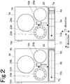
Fig. 2 is a plan view schematically showing the automatic analysis devices and the specimen transport device according to the embodiment. -
Fig. 3 is a block diagram showing an entire configuration according to the embodiment. -
Fig. 4 is a flowchart showing an example flow from setting of an operation mode to analysis start according to the embodiment. -
Fig. 5 is a flowchart showing an example flow from switching of an operation mode to analysis start according to the embodiment. -
Fig. 6 is a perspective view of a transport mechanism of the specimen transport device according to the embodiment. -
Fig. 7 is a side view of the transport mechanism. -
Fig. 8 is an exploded perspective view of the transport mechanism seen from obliquely above. - According to a mode of the present invention, a reagent which is common with a reagent installed on a reagent table of another automatic analysis device is installed on the reagent table of one automatic analysis device which is to be operated in a single operation mode, and an analysis item which uses the common reagent is preferably assigned to the other automatic analysis device in a multi-operation mode, and to the one automatic analysis device in the single operation mode. This allows an analysis item which was performed in the multi-operation mode by an automatic analysis device which is placed in a suspended state in the single operation mode to be performed by the one automatic analysis device which is operated in the single operation mode, and thus, occurrence of an analysis item which cannot be performed in the single operation mode may be prevented.
- A system control section that is electrically connected to an analysis control section of each automatic analysis device, and that manages operation of each automatic analysis device is further provided, and mode selection means, an assignment information holding section, analysis item setting means, and analysis item execution means are provided to the system control section. According to such a mode, all the automatic analysis devices may be integrally managed by the system control section, and management of the automatic analysis system by an operator is facilitated.
- An information display section that is electrically connected to the system control section, and that displays information output from the system control section is further provided, and the mode switching means displays, on the information display section, a mode selection screen urging an operator to select one of the multi-operation mode and the single operation mode, and causes the operator to select one of the multi-operation mode and the single operation mode on the mode selection screen. An operator may thereby perform switching between the multi-operation mode and the single operation mode on a display screen of the information display section, and switching of the modes is facilitated.
- Preferably, the analysis control section of each automatic analysis device also controls supply of power from a power supply device to a conveyor belt and an analysis operation section, and the system control section further includes non-operating device suspending means for supplying a signal for placing an automatic analysis device, other than an automatic analysis device that is to be placed in an operation state, in a suspended state in which supply of power from the power supply device to the conveying section and the analysis operation section is cut off, to the analysis control section of a corresponding automatic analysis device. An automatic analysis device which is not scheduled to be operated is thereby automatically placed in the suspended state, and wasteful consumption of power and the like may be proposed.
- According to a preferred mode of the present invention, the conveying section provided to each automatic analysis device is a conveyor belt that includes a beginning and an end, and that conveys a specimen container in one direction from a beginning side to an end side, and two automatic analysis devices that are adjacent to each other are arranged in such a way that the end of the conveyor belt of one automatic analysis device is close to and faces the beginning of the conveyor belt provided to the other automatic analysis device, and a specimen transport device includes a transport mechanism that is arranged between the conveyor belts of the two automatic analysis devices that are adjacent to each other, and that holds a specimen container which reached the end of one conveyor belt and transports the specimen container to the beginning of the other conveyor belt. According to such a configuration, the size of the entire analysis system may be reduced.
- An embodiment of the automatic analysis system will be described with reference to
Figs. 1 and2 .Figs. 1 and2 show two automatic analysis devices constituting the automatic analysis system, and a specimen transport device coupling the automatic analysis devices. A control device for managing the operation of these devices will be described later. - An
automatic analysis system 1 is configured by an analysis device group including twoautomatic analysis devices specimen transport device 12, and a control device 34 (seeFig. 3 ) connected to thesedevices automatic analysis devices sections automatic analysis devices specimen transport device 12. In the present embodiment, although the analysis device group is configured by the twoautomatic analysis devices specimen transport devices 12 become necessary. - The
automatic analysis device 2a includes ananalysis operation section 4a, aconveying section 6a, and aspecimen introduction mechanism 18a. Theautomatic analysis device 2b likewise includes ananalysis operation section 4a, aconveying section 6a, and aspecimen introduction mechanism 18a. Theautomatic analysis device 2a and theautomatic analysis device 2b include respectivepower supply devices Fig. 3 ), and an operator may turn on/off power of eachdevice power switch automatic analysis devices - The
automatic analysis devices automatic analysis device 2a will be described. Theconveying section 6a includes aconveyor belt 7a for conveying aspecimen rack 20 holding a specimen container in one direction in the X-direction (the direction of right to left inFigs. 1 and2 ) . The surrounding portion of theconveyor belt 7a is covered by a cover. A specimenrack placement section 8a is provided on the beginning side of theconveying section 6a (the right side inFigs. 1 and2 ), and a specimenrack recovery section 10a is provided on the end side (the left side in the drawings). Covers of the specimenrack placement section 8a and the specimenrack recovery section 10a can be opened/closed, and an operator may open the cover of the specimenrack placement section 8a and arrange a specimen rack on theconveyor belt 7a, or may open the cover of the specimenrack recovery section 10a and take out a specimen rack for which sampling is completed. - The
specimen introduction mechanism 18a moves in a Y-direction orthogonal to the X-direction on the horizontal plane, and holds aspecimen rack 20 on theconveyor belt 7a and introduces thespecimen rack 20 to the side of theanalysis operation section 4a, or returns aspecimen rack 20 for which sampling has been completed onto theconveyor belt 7a. A specimenrack introduction section 9a is provided between the specimenrack placement section 8a and the specimenrack recovery section 10a of the conveyingsection 6a. Although not shown, a stopper for stopping aspecimen rack 20 conveyed by theconveyor belt 7a and for releasing the stoppedspecimen rack 20 is provided to the specimenrack introduction section 9a. Thespecimen introduction mechanism 18a holds thespecimen rack 20 stopped at a predetermined position by the stopper, and transfers thespecimen rack 20 into theanalysis operation section 4a. Further, the specimen introduction mechanism 18 returns, at the specimenrack introduction section 9a, onto theconveyor belt 7a, aspecimen rack 20 in which the processing at theanalysis operation section 4a is completed. - The
analysis operation section 4a includes, in addition to a specimen collection mechanism (not shown) including, for example, a suction probe for collecting a specimen from a specimen container transferred by thespecimen introduction mechanism 18a, areagent installation section 22a, a specimenrack housing section 24a, and ameasurement section 26a. A plurality of specimen racks 20 transferred from theconveyor belt 7a by thespecimen introduction mechanism 18a are housed in the specimenrack housing section 24a. The specimenrack housing section 24a is a turntable, and places a specimen container on aspecimen rack 20 at a predetermined position where a specimen is collected by the suction probe. - A plurality of
reagent holders 23a for installing reagent containers containing reagents are provided to thereagent installation section 22a. Reagent information about a reagent container installed in eachreagent holder 23a of thereagent installation section 22a is input to the control device 34 (seeFig. 3 ) by an operator inputting the reagent information about an installed reagent container to thecontrol device 34 or by a bar code reader, as an information reader, reading information of a bar code which is an information medium attached to each reagent container, and what reagent is contained in whichreagent holder 23a is registered in thecontrol device 34. - A plurality of containers for mixing a specimen collected by the suction probe and a reagent are provided at the
measurement section 26a, and reaction in a container is optically measured. According to such a configuration, at theanalysis operation section 4a, aspecimen rack 20 is housed in the specimenrack housing section 24a by thespecimen introduction mechanism 18a, a specimen container held by thespecimen rack 20 is placed at a predetermined position, and a specimen is collected by the suction probe. The collected specimen is injected into a container provided at themeasurement section 26a, and after a reagent according to an analysis item is added by the suction probe, reaction between the specimen and the reagent is optically measured in terms of absorbance, fluorescence intensity, or the like. - The
conveyor belt 7b of theautomatic analysis device 2b is arranged on the same straight line as theconveyor belt 7a of theautomatic analysis device 2a, and the beginning of theconveyor belt 7b is arranged facing the end of theconveyor belt 7a. - The
specimen transport device 12 is arranged between theconveyor belts conveyor belts specimen transport device 12 includes a transport mechanism 100 (seeFigs. 6 to 8 ) for holding aspecimen rack 20 which reached the end of theconveyor belt 7a and for placing thespecimen rack 20 on the beginning of theconveyor belt 7b, and the transport mechanism is covered by anopenable shielding cover 14. Thespecimen transport device 12 includes afirst sensor 110 for detecting aspecimen rack 20 which reached the end of theconveyor belt 7a, and asecond sensor 112 for detecting aspecimen rack 20 which reached the beginning of theconveyor belt 7b (seeFigs. 6 to 8 ) . When aspecimen rack 20 is determined by the first sensor to have reached the end of theconveyor belt 7a, thespecimen transport device 12 automatically starts transporting thespecimen rack 20. - Next, a control system of the entire
automatic analysis system 1 will be described with reference toFig. 3 . - The
automatic analysis device 2a includes ananalysis control section 32a for controlling the operation and managing the states of theanalysis operation section 4a, theconveyor belt 7a, and thespecimen introduction mechanism 18a, and apower supply device 33a for supplying necessary power to each part mentioned above. Thepower supply device 33a is provided with apower switch 15a, and switching between on and off of supply of power to theanalysis operation section 4a, theconveyor belt 7a, thespecimen introduction mechanism 18a, and theanalysis control section 32a is performed by thepower switch 15a. - In the same manner, the
automatic analysis device 2b includes ananalysis control section 32b for controlling the operation and managing the states of theanalysis operation section 4b, theconveyor belt 7b, and thespecimen introduction mechanism 18b, and apower supply device 33b for supplying necessary power to each part mentioned above. Thepower supply device 33b is provided with apower switch 15a, and switching between on and off of supply of power to theanalysis operation section 4b, theconveyor belt 7b, thespecimen introduction mechanism 18b, and theanalysis control section 32b is performed by thepower switch 15b. - The
specimen transport device 12 includes thetransport mechanism 100 for transporting a specimen rack, thefirst sensor 110 for detecting aspecimen rack 20 which reached the end of theconveyor belt 7a, thesecond sensor 112 for detecting aspecimen rack 20 which reached the beginning of theconveyor belt 7b, and atransport control section 101 for controlling the operation of thetransport mechanism 100. Detection signals of thefirst sensor 110 and thesecond sensor 112 are captured by thecontrol device 34 via thetransport control section 101, and the transport state of aspecimen rack 20 at thespecimen transport device 12 is managed by thecontrol device 34. - The
analysis control sections transport control section 101 are connected to thecontrol device 34 by communication cables, and communication of information to/from thecontrol device 34 is thereby performed. Thecontrol device 34 is a system control section for managing and controlling the entire automatic analysis system. Thecontrol device 34 may be realized by a computer dedicated to the automatic analysis system, or by a general-purpose personal computer. - The
control device 34 includes analysis item assignment means 35, analysis item display means 36, analysis item setting means 37, analysis item execution means 38, mode switching means 39, an assignmentinformation holding section 40, and a non-operatingdevice suspending means 42. - The analysis item assignment means 35 allows an operator to perform setting regarding assignment of analysis items to be performed at each
automatic analysis device automatic analysis devices automatic analysis devices reagent installation section - As the operation modes, two operation modes of a multi-operation mode and a single operation mode are prepared for the automatic analysis system. The multi-operation mode is a mode in which analyses are performed by operating both of the
automatic analysis devices automatic analysis devices automatic analysis device automatic analysis device automatic analysis device automatic analysis device - The analysis item assignment means 35 assigns analysis items to each
automatic analysis device information holding section 40 as assignment information. - The mode switching means 39 is provided for switching between the operation modes. When switching of the operation mode is selected by an operator, the mode switching means 39 displays a mode selection screen on an
information display section 44, and causes the operator to select one of the multi-operation mode and the single operation mode on theinformation display section 44. - A specimen which is introduced into the automatic analysis system is identified by reading a bar code attached to the specimen container, for example, and is managed in association with an analysis item which is to be performed on the specimen. The
control device 34 controls the operation of theconveyor belt transport mechanism 100 through theanalysis control section transport control section 101 in such a way that each specimen is introduced into theautomatic analysis device - In response to a request from an operator, the analysis item display means 36 displays, on the
information display section 44, an analysis item that can be performed. Theinformation display section 44 is, for example, a touch panel liquid crystal display device. The analysis item setting means 37 sets an analysis item selected by the operator from the analysis items displayed on theinformation display section 44 as an analysis item to be performed on a target specimen. The analysis item execution means 38 transmits information about the analysis item set by the analysis item setting means 37 to theautomatic analysis device - At the time of, or after, installing a specimen container in the automatic analysis system, the operator causes analysis items which can be performed to be displayed on the
information display section 44, and selects, on theinformation display section 44, an analysis item to be performed from the displayed analysis items. When an analysis item is selected by the operator, information about the analysis item and information about the installed specimen container are associated with each other, and are transmitted from thecontrol device 34 to theautomatic analysis device automatic analysis device control device 34. - When the operation mode of the automatic analysis system is switched to the single operation mode, the non-operating device suspending means 42 transmits a signal, for achieving a suspended state, to an automatic analysis device which is not to be operated, and places the automatic analysis device in the suspended state. The suspended state is, for example, a state in which supply of power to a module other than modules which should be operated at all times is stopped. Modules which should be operated at all times include temperature adjustment elements, such as Peltier devices of the
reagent installation sections - Communication between an automatic analysis device in the suspended state and the
control device 34 is cut off, and even if the power of the automatic analysis device is turned off by thepower switch control device 34 as an error. - Furthermore, the non-operating
device suspending means 42 may stop supply of power to thetransport mechanism 100, thefirst sensor 110, and thesecond sensor 112 of thespecimen transport device 12 when the operation mode is switched to the single operation mode. The power consumption at the time of the single operation mode may thereby be further reduced. - A flow from start of the automatic analysis system to analysis start will be described with reference to
Fig. 3 and the flowchart inFig. 4 . - The
automatic analysis device 2a (analysis device 1) and theautomatic analysis device 2b (analysis device 2) are started, and reagent containers are installed in thereagent installation sections automatic analysis device reagent holding sections reagent installation sections automatic analysis device control device 34. Then, an analysis item is assigned to eachautomatic analysis device automatic analysis device information holding section 40 as assignment information. - For example, in the case where there are analysis items A, B, C, D, E, and F, in the multi-operation mode, the analysis items A, B, and C are assigned to the
automatic analysis device 2a, and the analysis items D, E, and F are assigned to theautomatic analysis device 2b. On the other hand, in the single operation mode, the analysis items A, B, C, D, E, and F are assigned to theautomatic analysis device 2a, and the analysis items D, E, and F are assigned to theautomatic analysis device 2b. In this case, reagents to be used for the analysis items A, B, C, D, E, and F all have to be installed in thereagent installation section 22a of theautomatic analysis device 2a. The reagents for the analysis items D, E, and F installed in thereagent installation section 22a of theautomatic analysis device 2a are used only in the single operation mode, and are not used in the multi-operation mode. Additionally, all the reagents for the analysis items A, B, C, D, E, and F may also be installed in thereagent installation section 22b of theautomatic analysis device 2b, and A, B, C, D, E, and F may also be assigned to theautomatic analysis device 2b as the analysis items for the time of the single operation mode. This allows all the analysis items to be performed in the single operation mode regardless of which of theautomatic analysis devices - Next, the mode switching means 39 causes the
information display section 44 to display the mode selection screen, and causes the operator to select an operation mode. - In the case where the multi-operation mode is selected, analysis items to be performed are assigned to the
automatic analysis devices information holding section 40. Then, when the operator installs a specimen and selects an analysis item to be performed on the specimen, the specimen is introduced into theautomatic analysis device - In the case where the single operation mode is selected, a screen for allowing the operator to select the
automatic analysis device information display section 44, and one of theautomatic analysis devices automatic analysis device automatic analysis device information holding section 40. The non-operating device suspending means 42 transmits a signal for placing the otherautomatic analysis device automatic analysis device automatic analysis device automatic analysis device - Additionally, in the present embodiment, although an operator is to select the
automatic analysis device automatic analysis device 2a) may be constantly set as the automatic analysis device to be operated alone in the single operation mode. - Next, a flow from switching of the operation mode to analysis start will be described with reference to
Figs. 3 and5 . - According to the automatic analysis system, an operator is allowed to switch the operation mode at a desired timing. When switching of the operation mode is input to the
control device 34 by an operator, the mode switching means 39 checks the current operation mode, and if the current operation mode is the multi-operation mode, selection of the automatic analysis device to be operated alone, setting of a reagent map to be used, extraction and setting of analysis items that can be performed, and placement of the automatic analysis device which is not to be operated in the suspended state are performed, and analysis in the single operation mode is started. - On the other hand, if the current operation mode is the single operation mode, a suspended automatic analysis device is restored to the operation state, and creation of a reagent map for the multi-operation mode, extraction of analysis items that can be performed, and setting of the automatic analysis devices which are to perform respective analysis items are performed, and analysis in the multi-operation mode is started. If the power of an automatic analysis device to be restored to the operation state is turned off at the time of switching of the operation mode from the single operation mode to the multi-operation mode, the
information display section 44 preferably performs display urging the operator to turn on the corresponding automatic analysis device. - Next, an example of the
transport mechanism 100 provided to thespecimen transport device 12 will be described with reference toFigs. 6 to 8 . - The
transport mechanism 100 includes a table 102 having a horizontal plane. The table 102 is supported by abase 118. The horizontal plane of the table 102 is set to approximately the same height as the conveyance surfaces of theconveyor belts conveyance start position 103a where conveyance of a specimen rack is started, and the end of theconveyor belt 7a on the former stage is arranged at theconveyance start position 103a. The position near an end on the other side of the table 102 in the X-direction (the left side in the drawing) is aconveyance end position 103b for a specimen rack, and the beginning of theconveyor belt 7b on the latter stage is arranged at theconveyance end position 103b. - An
arm member 104 and anarm member 106 extending in the X-direction are arranged, facing each other, at both side edge portions of the table 102. Thearm member 104 and thearm member 106 are driven in the X-direction and the Y-direction at the side edge portions of the table 102. Thearm member 104 and thearm member 106 move at the same time in the same direction in coordination with each other with respect to the X-direction, and move in symmetrical directions around the table 102 in coordination with each other with respect to the Y-direction. Although not shown, mechanisms, such as motors, for driving thearm member 104 and thearm member 106 are housed inside thebase 118. - The
arm member 104 includes aprotrusion 104a, which faces the inner side (the table 102 side in the Y-direction), at the end portion on theconveyance start position 103a side, and also includes aprotrusion 104b, which faces the inner side, at the end portion on thetransport end position 103b side. Theprotrusion 104a and theprotrusion 104b protrude toward the table 102 side in the Y-direction. Recesses (not shown) are provided at a side surface of thespecimen rack 20 . Thespecimen rack 20 is placed on the table 20 with the recesses facing the outer side in the Y-direction. Theprotrusions specimen rack 20 to be engaged with the specimen rack. Thearm member 104 is moved, in the Y-direction, between a position where theprotrusions - The
arm member 106 includes aprotrusion 106a, which faces the inner side (the table 102 side in the Y-direction), at the end portion on theconveyance start position 103a side, and also includes aprotrusion 106b, which faces the inner side, on thetransport end position 103b side. Theprotrusion 106a and theprotrusion 106b are to engage with a rear surface (with respect to the traveling direction) of the specimen rack. Thearm member 106 is moved, in the Y-direction, between a position where theprotrusions protrusions - The
arm members conveyance start position 103a to thetransport end position 103b. The handler configures holding sections at two positions, on the side of theconveyance start position 103a and on the side of thetransport end position 103b. The holding section on the side of theconveyance start position 103a is configured by theprotrusion 104a of thearm member 104 and theprotrusion 106a of thearm member 106, and the holding section on the side of thetransport end position 103b is configured by theprotrusion 104b of thearm member 104 and theprotrusion 106b of thearm member 106. - In the following, the
arm member 104 and thearm member 106 will be collectively referred to as "handler handler conveyance start position 103a as "first holding section transport end position 103b as "second holding section - The
first holding section handler conveyance start position 103a to thereby fit theprotrusion 104a in the recess on one side surface of the specimen rack and to support the opposite rear surface of the specimen rack by theprotrusion 106a. Thesecond holding section arm members conveyance start position 103b to thereby fit theprotrusion 104b in the recess on one side surface of the specimen rack and to support the opposite rear surface of the specimen rack by theprotrusion 106b. Thehandler - A
guide rail 108, which is fitted in a groove on a side surface of the specimen rack sliding on the table 102 and which prevents the specimen rack from falling over, is provided at a side edge portion of the table 102, on the side of thearm member 106. - The
first sensor 110 for detecting the specimen rack reaching theconveyance start position 103a is provided at a side of theconveyance start position 103a. Thesecond sensor 112 for detecting the specimen rack reaching thetransport end position 103b is provided at a side of thetransport end position 103b. - A
stopper 114 is provided near theconveyance start position 103a, and thespecimen rack 20 conveyed by theconveyor belt 7a is stopped at theconveyance start position 103a. Thestopper 114 stops thespecimen rack 20 at theconveyance start position 103a until immediately before thespecimen rack 20 is held by thehandler stopper 114 is released when thehandler specimen rack 20 and starts transporting thespecimen rack 20. - A
circuit board 116 is provided at a side portion of thebase 118. Thecircuit board 116 is thetransport control section 101 for controlling the operation of thehandler first sensor 110 and thesecond sensor 112 are connected to thecircuit board 116 by wires, and detection signals of the sensors are thereby captured by thecircuit board 116. Thecircuit board 116 starts the transport operation for the specimen rack based on a detection signal obtained at the time of detection of arrival of the specimen rack by thefirst sensor 110. - The
circuit board 116 is connected to thecontrol device 34, and detection signals of thefirst sensor 110 and thesecond sensor 112 are captured by thecontrol device 34 through thecircuit board 116, and the transport state of the specimen rack at thespecimen transport device 12 is managed by thecontrol device 34. - Additionally, wires and modules mounted on the
circuit board 116 are omitted fromFig. 7 .Fig. 8 shows some of the modules mounted on thecircuit board 116, but does not show the wires. -
- 1:
- Automatic analysis system
- 2a, 2b:
- Automatic analysis device
- 4a, 4b:
- Analysis operation section
- 6a, 6b:
- Conveying section
- 7a, 7b:
- Conveyor belt
- 8a, 8b:
- Specimen rack placement section
- 9a, 9b:
- Specimen rack introduction section
- 10a, 10b:
- Specimen rack recovery section
- 12:
- Specimen transport device
- 14:
- Shielding cover
- 15a, 15b:
- Power switch
- 18a, 18b:
- Specimen introduction mechanism
- 20:
- Specimen rack
- 22a, 22b:
- Reagent installation section
- 24a, 24b:
- Specimen rack housing section
- 26a, 26b:
- Measurement section
- 32a, 32b:
- Analysis control section
- 33a, 33b:
- Power supply device
- 34:
- Control device
- 35:
- Analysis item assignment means
- 36:
- Analysis item display means
- 37:
- Analysis item setting means
- 38:
- Analysis item execution means
- 39:
- Mode switching means
- 40:
- Assignment information holding section
- 42:
- Non-operating device suspending means
- 44:
- Information display section
- 100:
- Transport mechanism
- 101a:
- X-direction drive motor
- 101b:
- Y-direction drive motor
- 102:
- Table
- 103a:
- Conveyance start position
- 103b:
- Conveyance end position
- 104, 106:
- Arm member (handler)
- 104a, 104b, 106a, 106b:
- Protrusion (holding section)
- 108:
- Guide rail
- 110:
- First sensor
- 112:
- Second sensor
- 114:
- Stopper
- 116:
- Circuit board (control section)
- 116a:
- Motor driver
- 118:
- Base
Claims (6)
- An automatic analysis system comprising:an analysis device group including a plurality of automatic analysis devices each including a conveying section for conveying a specimen container containing a specimen, a reagent table on which a plurality of reagent containers containing reagents are to be installed, an analysis operation section for collecting a specimen from a specimen container conveyed by the conveying section to a predetermined position, and for performing analysis by adding a reagent, among reagents installed on the reagent table, to the specimen, a power supply device for supplying necessary power to the conveying section and the analysis operation section, and an analysis control section for controlling operation of the conveying section and the analysis operation section;a specimen transport device for coupling two automatic analysis devices that are adjacent to each other, and for transporting a specimen container between the automatic analysis devices;mode switching means for selecting, and switching to, one of a multi-operation mode in which a plurality of automatic analysis devices that are coupled to each other by the specimen transport device are placed in an operation state and a single operation mode in which only one automatic analysis device is placed in the operation state;an assignment information holding section for holding analysis item assignment information assigned in advance to each automatic analysis device as an analysis item to be performed by each of the automatic analysis devices in the analysis device group in each of the multi-operation mode and the single operation mode;analysis item setting means for setting, in each of the modes, an analysis item, among analysis items assigned to each of the automatic analysis devices, as an analysis item to be performed on an analysis target specimen, based on the analysis item assignment information held in the assignment information holding section; andanalysis item execution means for supplying information about the analysis item set by the analysis item setting means to the analysis control section of each automatic analysis device, and for causing the analysis item to be performed on a specimen on which the analysis item is to be performed.
- The automatic analysis system according to claim 1, wherein a reagent that is common with a reagent installed on the reagent table of another automatic analysis device is installed on the reagent table of one automatic analysis device that is to be operated in the single operation mode, and an analysis item that uses the common reagent is assigned to the other automatic analysis device in the multi-operation mode, and is assigned to the one automatic analysis device in the single operation mode.
- The automatic analysis system according to claim 1 or 2, comprising a system control section that is electrically connected to the analysis control section of each of the automatic analysis devices, and that manages operation of each of the automatic analysis devices,
wherein the mode switching means, the assignment information holding section, and the analysis item execution means are provided to the system control section. - The automatic analysis system according to claim 2 or 3, further comprising an information display section that is electrically connected to the system control section, and that displays information output from the system control section,
wherein the mode switching means displays, on the information display section, a mode selection screen urging an operator to select one of the multi-operation mode and the single operation mode, and causes the operator to select one of the multi-operation mode and the single operation mode on the mode selection screen. - The automatic analysis system according to any one of claims 2 to 4,
wherein the analysis control section of each of the automatic analysis devices also controls supply of power from the power supply device to the conveyor belt and the analysis operation section, and
wherein the system control section further includes non-operating device suspending means for supplying a signal for placing an automatic analysis device, other than an automatic analysis device that is to be placed in the operation state, in a suspended state in which supply of power from the power supply device to the conveying section and the analysis operation section is cut off, to the analysis control section of a corresponding automatic analysis device. - The automatic analysis system according to any one of claims 1 to 5,
wherein the conveying section provided to each of the automatic analysis devices is a conveyor belt that includes a beginning and an end, and that conveys a specimen container in one direction from a beginning side to an end side,
wherein two automatic analysis devices that are adjacent to each other are arranged in such a way that the end of the conveyor belt of one automatic analysis device is close to and faces the beginning of the conveyor belt provided to other automatic analysis device, and
wherein the specimen transport device includes a transport mechanism that is arranged between the conveyor belts of the two automatic analysis devices that are adjacent to each other, and that holds a specimen container that reached the end of one conveyor belt and transports the specimen container to the beginning of other conveyor belt.
Applications Claiming Priority (1)
| Application Number | Priority Date | Filing Date | Title |
|---|---|---|---|
| PCT/JP2014/079834 WO2016075755A1 (en) | 2014-11-11 | 2014-11-11 | Automatic analysis system |
Publications (3)
| Publication Number | Publication Date |
|---|---|
| EP3206035A1 true EP3206035A1 (en) | 2017-08-16 |
| EP3206035A4 EP3206035A4 (en) | 2018-07-18 |
| EP3206035B1 EP3206035B1 (en) | 2025-02-26 |
Family
ID=55953868
Family Applications (1)
| Application Number | Title | Priority Date | Filing Date |
|---|---|---|---|
| EP14905750.7A Active EP3206035B1 (en) | 2014-11-11 | 2014-11-11 | Automatic analysis system |
Country Status (3)
| Country | Link |
|---|---|
| EP (1) | EP3206035B1 (en) |
| JP (1) | JP6269856B2 (en) |
| WO (1) | WO2016075755A1 (en) |
Cited By (2)
| Publication number | Priority date | Publication date | Assignee | Title |
|---|---|---|---|---|
| WO2025111444A1 (en) * | 2023-11-22 | 2025-05-30 | Abbott Laboratories | Sample processing scheduling in laboratory diagnostic automation systems |
| EP4624930A1 (en) * | 2024-03-31 | 2025-10-01 | Shenzhen Mindray Bio-Medical Electronics Co., Ltd. | Sample analysis module and sample analysis system |
Families Citing this family (4)
| Publication number | Priority date | Publication date | Assignee | Title |
|---|---|---|---|---|
| CN111208311A (en) * | 2018-11-22 | 2020-05-29 | 深圳迈瑞生物医疗电子股份有限公司 | Sample analysis assembly line, sample analysis control device and method |
| EP3843104A1 (en) | 2019-12-23 | 2021-06-30 | F. Hoffmann-La Roche AG | Workload instrument masking |
| JP7559601B2 (en) * | 2021-02-18 | 2024-10-02 | 株式会社島津製作所 | Analytical equipment management system and program |
| JP7794000B2 (en) * | 2022-01-31 | 2026-01-06 | 株式会社島津製作所 | Unit-type analyzer |
Family Cites Families (8)
| Publication number | Priority date | Publication date | Assignee | Title |
|---|---|---|---|---|
| JP3725961B2 (en) * | 1997-04-09 | 2005-12-14 | 株式会社日立製作所 | Sample analysis system |
| DE69940647D1 (en) * | 1998-05-01 | 2009-05-07 | Gen Probe Inc | Automatic diagnostic analyzer |
| JP3616744B2 (en) * | 2000-06-07 | 2005-02-02 | シスメックス株式会社 | Sample transport system |
| JP4733315B2 (en) * | 2001-08-23 | 2011-07-27 | シスメックス株式会社 | Specimen inspection system, transfer control device and method |
| JP3990945B2 (en) * | 2002-06-28 | 2007-10-17 | 株式会社日立ハイテクノロジーズ | Automatic analyzer |
| JP4241434B2 (en) * | 2004-03-01 | 2009-03-18 | 株式会社日立ハイテクノロジーズ | Automatic analysis system |
| JP2008292328A (en) * | 2007-05-25 | 2008-12-04 | Shimadzu Corp | Analyzer management system |
| JP5606902B2 (en) * | 2010-12-27 | 2014-10-15 | シスメックス株式会社 | Information processing apparatus for sample measurement and sample measurement system |
-
2014
- 2014-11-11 JP JP2016558474A patent/JP6269856B2/en active Active
- 2014-11-11 EP EP14905750.7A patent/EP3206035B1/en active Active
- 2014-11-11 WO PCT/JP2014/079834 patent/WO2016075755A1/en not_active Ceased
Cited By (2)
| Publication number | Priority date | Publication date | Assignee | Title |
|---|---|---|---|---|
| WO2025111444A1 (en) * | 2023-11-22 | 2025-05-30 | Abbott Laboratories | Sample processing scheduling in laboratory diagnostic automation systems |
| EP4624930A1 (en) * | 2024-03-31 | 2025-10-01 | Shenzhen Mindray Bio-Medical Electronics Co., Ltd. | Sample analysis module and sample analysis system |
Also Published As
| Publication number | Publication date |
|---|---|
| EP3206035B1 (en) | 2025-02-26 |
| JPWO2016075755A1 (en) | 2017-04-27 |
| WO2016075755A1 (en) | 2016-05-19 |
| JP6269856B2 (en) | 2018-01-31 |
| EP3206035A4 (en) | 2018-07-18 |
Similar Documents
| Publication | Publication Date | Title |
|---|---|---|
| EP3206035B1 (en) | Automatic analysis system | |
| JP4637897B2 (en) | Device for supplying whole blood analyzer | |
| US8143065B2 (en) | Specimen processing device, specimen conveyance device, and specimen conveyance method | |
| JP5485767B2 (en) | Sample rack transport system | |
| JP5289798B2 (en) | Analytical apparatus and sample transport method | |
| JP2007309675A (en) | Sample rack supply-and-recovery system | |
| CN102023224B (en) | Recycle collecting unit and sample processing apparatus | |
| JP2015118091A (en) | Storage and supply for vessel holder | |
| CN114008459A (en) | Automatic sample introduction system, sample analysis system and automatic sample introduction control method | |
| US8738182B2 (en) | Sample processing apparatus | |
| CN107430143B (en) | Sample measurement system and rack carrying-in/out method | |
| JPWO2017047240A1 (en) | Automatic analyzer | |
| JP5999033B2 (en) | Automatic analysis system connecting multiple analyzers | |
| JP6065803B2 (en) | Automatic analysis system connecting multiple analyzers | |
| EP3940387B1 (en) | Automatic analysis device and automatic analysis method | |
| WO2011122606A1 (en) | Sample analysis system | |
| JP6941672B2 (en) | Automatic analyzer | |
| US8594836B2 (en) | Sample processing system, sample processing method, and computer program product | |
| CN107636469A (en) | Automatic analysing apparatus | |
| US20210255210A1 (en) | Autosampler, automatic analysis device, sampling method, and automatic inspection method | |
| JP3187844U (en) | Automatic analysis system connecting multiple analyzers | |
| WO2015189892A1 (en) | Automatic analysis system | |
| WO2015083236A1 (en) | Automatic analysis system obtained by linking plurality of analysis devices | |
| JP2009216459A (en) | Analyzer and measuring unit | |
| US20200408793A1 (en) | Testing system, storage device, and rack storage method |
Legal Events
| Date | Code | Title | Description |
|---|---|---|---|
| STAA | Information on the status of an ep patent application or granted ep patent |
Free format text: STATUS: THE INTERNATIONAL PUBLICATION HAS BEEN MADE |
|
| PUAI | Public reference made under article 153(3) epc to a published international application that has entered the european phase |
Free format text: ORIGINAL CODE: 0009012 |
|
| STAA | Information on the status of an ep patent application or granted ep patent |
Free format text: STATUS: REQUEST FOR EXAMINATION WAS MADE |
|
| 17P | Request for examination filed |
Effective date: 20170509 |
|
| AK | Designated contracting states |
Kind code of ref document: A1 Designated state(s): AL AT BE BG CH CY CZ DE DK EE ES FI FR GB GR HR HU IE IS IT LI LT LU LV MC MK MT NL NO PL PT RO RS SE SI SK SM TR |
|
| AX | Request for extension of the european patent |
Extension state: BA ME |
|
| DAX | Request for extension of the european patent (deleted) | ||
| RIC1 | Information provided on ipc code assigned before grant |
Ipc: G01N 35/00 20060101AFI20180606BHEP |
|
| A4 | Supplementary search report drawn up and despatched |
Effective date: 20180614 |
|
| STAA | Information on the status of an ep patent application or granted ep patent |
Free format text: STATUS: EXAMINATION IS IN PROGRESS |
|
| 17Q | First examination report despatched |
Effective date: 20210421 |
|
| GRAP | Despatch of communication of intention to grant a patent |
Free format text: ORIGINAL CODE: EPIDOSNIGR1 |
|
| STAA | Information on the status of an ep patent application or granted ep patent |
Free format text: STATUS: GRANT OF PATENT IS INTENDED |
|
| INTG | Intention to grant announced |
Effective date: 20240924 |
|
| GRAS | Grant fee paid |
Free format text: ORIGINAL CODE: EPIDOSNIGR3 |
|
| GRAA | (expected) grant |
Free format text: ORIGINAL CODE: 0009210 |
|
| STAA | Information on the status of an ep patent application or granted ep patent |
Free format text: STATUS: THE PATENT HAS BEEN GRANTED |
|
| AK | Designated contracting states |
Kind code of ref document: B1 Designated state(s): AL AT BE BG CH CY CZ DE DK EE ES FI FR GB GR HR HU IE IS IT LI LT LU LV MC MK MT NL NO PL PT RO RS SE SI SK SM TR |
|
| REG | Reference to a national code |
Ref country code: GB Ref legal event code: FG4D |
|
| REG | Reference to a national code |
Ref country code: CH Ref legal event code: EP |
|
| REG | Reference to a national code |
Ref country code: DE Ref legal event code: R096 Ref document number: 602014091623 Country of ref document: DE |
|
| REG | Reference to a national code |
Ref country code: IE Ref legal event code: FG4D |
|
| REG | Reference to a national code |
Ref country code: NL Ref legal event code: MP Effective date: 20250226 |
|
| PG25 | Lapsed in a contracting state [announced via postgrant information from national office to epo] |
Ref country code: RS Free format text: LAPSE BECAUSE OF FAILURE TO SUBMIT A TRANSLATION OF THE DESCRIPTION OR TO PAY THE FEE WITHIN THE PRESCRIBED TIME-LIMIT Effective date: 20250526 |
|
| PG25 | Lapsed in a contracting state [announced via postgrant information from national office to epo] |
Ref country code: FI Free format text: LAPSE BECAUSE OF FAILURE TO SUBMIT A TRANSLATION OF THE DESCRIPTION OR TO PAY THE FEE WITHIN THE PRESCRIBED TIME-LIMIT Effective date: 20250226 |
|
| PG25 | Lapsed in a contracting state [announced via postgrant information from national office to epo] |
Ref country code: PL Free format text: LAPSE BECAUSE OF FAILURE TO SUBMIT A TRANSLATION OF THE DESCRIPTION OR TO PAY THE FEE WITHIN THE PRESCRIBED TIME-LIMIT Effective date: 20250226 |
|
| PG25 | Lapsed in a contracting state [announced via postgrant information from national office to epo] |
Ref country code: ES Free format text: LAPSE BECAUSE OF FAILURE TO SUBMIT A TRANSLATION OF THE DESCRIPTION OR TO PAY THE FEE WITHIN THE PRESCRIBED TIME-LIMIT Effective date: 20250226 |
|
| REG | Reference to a national code |
Ref country code: LT Ref legal event code: MG9D |
|
| PG25 | Lapsed in a contracting state [announced via postgrant information from national office to epo] |
Ref country code: IS Free format text: LAPSE BECAUSE OF FAILURE TO SUBMIT A TRANSLATION OF THE DESCRIPTION OR TO PAY THE FEE WITHIN THE PRESCRIBED TIME-LIMIT Effective date: 20250626 Ref country code: NO Free format text: LAPSE BECAUSE OF FAILURE TO SUBMIT A TRANSLATION OF THE DESCRIPTION OR TO PAY THE FEE WITHIN THE PRESCRIBED TIME-LIMIT Effective date: 20250526 |
|
| PG25 | Lapsed in a contracting state [announced via postgrant information from national office to epo] |
Ref country code: NL Free format text: LAPSE BECAUSE OF FAILURE TO SUBMIT A TRANSLATION OF THE DESCRIPTION OR TO PAY THE FEE WITHIN THE PRESCRIBED TIME-LIMIT Effective date: 20250226 |
|
| PG25 | Lapsed in a contracting state [announced via postgrant information from national office to epo] |
Ref country code: HR Free format text: LAPSE BECAUSE OF FAILURE TO SUBMIT A TRANSLATION OF THE DESCRIPTION OR TO PAY THE FEE WITHIN THE PRESCRIBED TIME-LIMIT Effective date: 20250226 |
|
| PG25 | Lapsed in a contracting state [announced via postgrant information from national office to epo] |
Ref country code: LV Free format text: LAPSE BECAUSE OF FAILURE TO SUBMIT A TRANSLATION OF THE DESCRIPTION OR TO PAY THE FEE WITHIN THE PRESCRIBED TIME-LIMIT Effective date: 20250226 Ref country code: PT Free format text: LAPSE BECAUSE OF FAILURE TO SUBMIT A TRANSLATION OF THE DESCRIPTION OR TO PAY THE FEE WITHIN THE PRESCRIBED TIME-LIMIT Effective date: 20250626 |
|
| PG25 | Lapsed in a contracting state [announced via postgrant information from national office to epo] |
Ref country code: GR Free format text: LAPSE BECAUSE OF FAILURE TO SUBMIT A TRANSLATION OF THE DESCRIPTION OR TO PAY THE FEE WITHIN THE PRESCRIBED TIME-LIMIT Effective date: 20250527 Ref country code: BG Free format text: LAPSE BECAUSE OF FAILURE TO SUBMIT A TRANSLATION OF THE DESCRIPTION OR TO PAY THE FEE WITHIN THE PRESCRIBED TIME-LIMIT Effective date: 20250226 |
|
| REG | Reference to a national code |
Ref country code: AT Ref legal event code: MK05 Ref document number: 1771111 Country of ref document: AT Kind code of ref document: T Effective date: 20250226 |
|
| PG25 | Lapsed in a contracting state [announced via postgrant information from national office to epo] |
Ref country code: SE Free format text: LAPSE BECAUSE OF FAILURE TO SUBMIT A TRANSLATION OF THE DESCRIPTION OR TO PAY THE FEE WITHIN THE PRESCRIBED TIME-LIMIT Effective date: 20250226 |
|
| PG25 | Lapsed in a contracting state [announced via postgrant information from national office to epo] |
Ref country code: SM Free format text: LAPSE BECAUSE OF FAILURE TO SUBMIT A TRANSLATION OF THE DESCRIPTION OR TO PAY THE FEE WITHIN THE PRESCRIBED TIME-LIMIT Effective date: 20250226 |
|
| PG25 | Lapsed in a contracting state [announced via postgrant information from national office to epo] |
Ref country code: DK Free format text: LAPSE BECAUSE OF FAILURE TO SUBMIT A TRANSLATION OF THE DESCRIPTION OR TO PAY THE FEE WITHIN THE PRESCRIBED TIME-LIMIT Effective date: 20250226 |
|
| PG25 | Lapsed in a contracting state [announced via postgrant information from national office to epo] |
Ref country code: AT Free format text: LAPSE BECAUSE OF FAILURE TO SUBMIT A TRANSLATION OF THE DESCRIPTION OR TO PAY THE FEE WITHIN THE PRESCRIBED TIME-LIMIT Effective date: 20250226 |
|
| PG25 | Lapsed in a contracting state [announced via postgrant information from national office to epo] |
Ref country code: EE Free format text: LAPSE BECAUSE OF FAILURE TO SUBMIT A TRANSLATION OF THE DESCRIPTION OR TO PAY THE FEE WITHIN THE PRESCRIBED TIME-LIMIT Effective date: 20250226 Ref country code: CZ Free format text: LAPSE BECAUSE OF FAILURE TO SUBMIT A TRANSLATION OF THE DESCRIPTION OR TO PAY THE FEE WITHIN THE PRESCRIBED TIME-LIMIT Effective date: 20250226 |
|
| PG25 | Lapsed in a contracting state [announced via postgrant information from national office to epo] |
Ref country code: RO Free format text: LAPSE BECAUSE OF FAILURE TO SUBMIT A TRANSLATION OF THE DESCRIPTION OR TO PAY THE FEE WITHIN THE PRESCRIBED TIME-LIMIT Effective date: 20250226 |
|
| PG25 | Lapsed in a contracting state [announced via postgrant information from national office to epo] |
Ref country code: SK Free format text: LAPSE BECAUSE OF FAILURE TO SUBMIT A TRANSLATION OF THE DESCRIPTION OR TO PAY THE FEE WITHIN THE PRESCRIBED TIME-LIMIT Effective date: 20250226 |
|
| REG | Reference to a national code |
Ref country code: DE Ref legal event code: R097 Ref document number: 602014091623 Country of ref document: DE |
|
| PLBE | No opposition filed within time limit |
Free format text: ORIGINAL CODE: 0009261 |
|
| STAA | Information on the status of an ep patent application or granted ep patent |
Free format text: STATUS: NO OPPOSITION FILED WITHIN TIME LIMIT |
|
| REG | Reference to a national code |
Ref country code: CH Ref legal event code: L10 Free format text: ST27 STATUS EVENT CODE: U-0-0-L10-L00 (AS PROVIDED BY THE NATIONAL OFFICE) Effective date: 20260107 |
|
| PGFP | Annual fee paid to national office [announced via postgrant information from national office to epo] |
Ref country code: IT Payment date: 20251022 Year of fee payment: 12 |
|
| 26N | No opposition filed |
Effective date: 20251127 |
|
| REG | Reference to a national code |
Ref country code: DE Ref legal event code: R119 Ref document number: 602014091623 Country of ref document: DE |
|
| REG | Reference to a national code |
Ref country code: CH Ref legal event code: H13 Free format text: ST27 STATUS EVENT CODE: U-0-0-H10-H13 (AS PROVIDED BY THE NATIONAL OFFICE) Effective date: 20260623 |
|
| PG25 | Lapsed in a contracting state [announced via postgrant information from national office to epo] |
Ref country code: LT Free format text: LAPSE BECAUSE OF FAILURE TO SUBMIT A TRANSLATION OF THE DESCRIPTION OR TO PAY THE FEE WITHIN THE PRESCRIBED TIME-LIMIT Effective date: 20250226 |
|
| PG25 | Lapsed in a contracting state [announced via postgrant information from national office to epo] |
Ref country code: MC Free format text: LAPSE BECAUSE OF FAILURE TO SUBMIT A TRANSLATION OF THE DESCRIPTION OR TO PAY THE FEE WITHIN THE PRESCRIBED TIME-LIMIT Effective date: 20250226 |
|
| PG25 | Lapsed in a contracting state [announced via postgrant information from national office to epo] |
Ref country code: CH Free format text: LAPSE BECAUSE OF NON-PAYMENT OF DUE FEES Effective date: 20251130 Ref country code: LU Free format text: LAPSE BECAUSE OF NON-PAYMENT OF DUE FEES Effective date: 20251111 |