EP3206029B1 - Sensor chip with electrostatic discharge protection element - Google Patents
Sensor chip with electrostatic discharge protection element Download PDFInfo
- Publication number
- EP3206029B1 EP3206029B1 EP16163475.3A EP16163475A EP3206029B1 EP 3206029 B1 EP3206029 B1 EP 3206029B1 EP 16163475 A EP16163475 A EP 16163475A EP 3206029 B1 EP3206029 B1 EP 3206029B1
- Authority
- EP
- European Patent Office
- Prior art keywords
- protection element
- sensor device
- carrier
- electronic component
- sensor chip
- Prior art date
- Legal status (The legal status is an assumption and is not a legal conclusion. Google has not performed a legal analysis and makes no representation as to the accuracy of the status listed.)
- Active
Links
- 229910000679 solder Inorganic materials 0.000 claims description 12
- 230000000284 resting effect Effects 0.000 claims description 9
- 238000000034 method Methods 0.000 claims description 8
- 238000004519 manufacturing process Methods 0.000 claims description 7
- 238000005476 soldering Methods 0.000 claims description 7
- 238000010586 diagram Methods 0.000 description 20
- 239000011248 coating agent Substances 0.000 description 7
- 238000000576 coating method Methods 0.000 description 7
- XUIMIQQOPSSXEZ-UHFFFAOYSA-N Silicon Chemical compound [Si] XUIMIQQOPSSXEZ-UHFFFAOYSA-N 0.000 description 6
- 229910052710 silicon Inorganic materials 0.000 description 6
- 239000010703 silicon Substances 0.000 description 6
- 239000000758 substrate Substances 0.000 description 6
- 239000007788 liquid Substances 0.000 description 5
- 239000000463 material Substances 0.000 description 5
- 239000002184 metal Substances 0.000 description 5
- 239000000919 ceramic Substances 0.000 description 4
- 238000005538 encapsulation Methods 0.000 description 4
- 239000004065 semiconductor Substances 0.000 description 4
- VYPSYNLAJGMNEJ-UHFFFAOYSA-N Silicium dioxide Chemical compound O=[Si]=O VYPSYNLAJGMNEJ-UHFFFAOYSA-N 0.000 description 3
- 239000004020 conductor Substances 0.000 description 3
- 239000012530 fluid Substances 0.000 description 3
- 239000007789 gas Substances 0.000 description 3
- 239000011521 glass Substances 0.000 description 3
- 238000010438 heat treatment Methods 0.000 description 3
- 238000007689 inspection Methods 0.000 description 3
- 230000003287 optical effect Effects 0.000 description 3
- 229910052814 silicon oxide Inorganic materials 0.000 description 3
- 230000009286 beneficial effect Effects 0.000 description 2
- 230000007613 environmental effect Effects 0.000 description 2
- 150000002500 ions Chemical class 0.000 description 2
- 239000004033 plastic Substances 0.000 description 2
- 229920003023 plastic Polymers 0.000 description 2
- 229910000906 Bronze Inorganic materials 0.000 description 1
- 238000004026 adhesive bonding Methods 0.000 description 1
- 230000003321 amplification Effects 0.000 description 1
- 239000012491 analyte Substances 0.000 description 1
- 239000010974 bronze Substances 0.000 description 1
- 239000003990 capacitor Substances 0.000 description 1
- 150000001875 compounds Chemical class 0.000 description 1
- KUNSUQLRTQLHQQ-UHFFFAOYSA-N copper tin Chemical compound [Cu].[Sn] KUNSUQLRTQLHQQ-UHFFFAOYSA-N 0.000 description 1
- 230000001419 dependent effect Effects 0.000 description 1
- 239000003989 dielectric material Substances 0.000 description 1
- 238000011156 evaluation Methods 0.000 description 1
- 230000005669 field effect Effects 0.000 description 1
- 230000005484 gravity Effects 0.000 description 1
- 230000001771 impaired effect Effects 0.000 description 1
- 239000012212 insulator Substances 0.000 description 1
- 238000003199 nucleic acid amplification method Methods 0.000 description 1
- 229920000642 polymer Polymers 0.000 description 1
- 230000001681 protective effect Effects 0.000 description 1
- 239000000126 substance Substances 0.000 description 1
Images

Classifications
-
- G—PHYSICS
- G01—MEASURING; TESTING
- G01N—INVESTIGATING OR ANALYSING MATERIALS BY DETERMINING THEIR CHEMICAL OR PHYSICAL PROPERTIES
- G01N33/00—Investigating or analysing materials by specific methods not covered by groups G01N1/00 - G01N31/00
- G01N33/0004—Gaseous mixtures, e.g. polluted air
- G01N33/0009—General constructional details of gas analysers, e.g. portable test equipment
- G01N33/0027—General constructional details of gas analysers, e.g. portable test equipment concerning the detector
-
- G—PHYSICS
- G01—MEASURING; TESTING
- G01N—INVESTIGATING OR ANALYSING MATERIALS BY DETERMINING THEIR CHEMICAL OR PHYSICAL PROPERTIES
- G01N27/00—Investigating or analysing materials by the use of electric, electrochemical, or magnetic means
- G01N27/02—Investigating or analysing materials by the use of electric, electrochemical, or magnetic means by investigating impedance
- G01N27/04—Investigating or analysing materials by the use of electric, electrochemical, or magnetic means by investigating impedance by investigating resistance
- G01N27/12—Investigating or analysing materials by the use of electric, electrochemical, or magnetic means by investigating impedance by investigating resistance of a solid body in dependence upon absorption of a fluid; of a solid body in dependence upon reaction with a fluid, for detecting components in the fluid
- G01N27/121—Investigating or analysing materials by the use of electric, electrochemical, or magnetic means by investigating impedance by investigating resistance of a solid body in dependence upon absorption of a fluid; of a solid body in dependence upon reaction with a fluid, for detecting components in the fluid for determining moisture content, e.g. humidity, of the fluid
-
- G—PHYSICS
- G01—MEASURING; TESTING
- G01N—INVESTIGATING OR ANALYSING MATERIALS BY DETERMINING THEIR CHEMICAL OR PHYSICAL PROPERTIES
- G01N33/00—Investigating or analysing materials by specific methods not covered by groups G01N1/00 - G01N31/00
-
- G—PHYSICS
- G01—MEASURING; TESTING
- G01N—INVESTIGATING OR ANALYSING MATERIALS BY DETERMINING THEIR CHEMICAL OR PHYSICAL PROPERTIES
- G01N33/00—Investigating or analysing materials by specific methods not covered by groups G01N1/00 - G01N31/00
- G01N33/0004—Gaseous mixtures, e.g. polluted air
- G01N33/0009—General constructional details of gas analysers, e.g. portable test equipment
-
- H—ELECTRICITY
- H01—ELECTRIC ELEMENTS
- H01L—SEMICONDUCTOR DEVICES NOT COVERED BY CLASS H10
- H01L23/00—Details of semiconductor or other solid state devices
- H01L23/28—Encapsulations, e.g. encapsulating layers, coatings, e.g. for protection
- H01L23/31—Encapsulations, e.g. encapsulating layers, coatings, e.g. for protection characterised by the arrangement or shape
- H01L23/3157—Partial encapsulation or coating
-
- H—ELECTRICITY
- H01—ELECTRIC ELEMENTS
- H01L—SEMICONDUCTOR DEVICES NOT COVERED BY CLASS H10
- H01L23/00—Details of semiconductor or other solid state devices
- H01L23/58—Structural electrical arrangements for semiconductor devices not otherwise provided for, e.g. in combination with batteries
- H01L23/585—Structural electrical arrangements for semiconductor devices not otherwise provided for, e.g. in combination with batteries comprising conductive layers or plates or strips or rods or rings
-
- H—ELECTRICITY
- H01—ELECTRIC ELEMENTS
- H01L—SEMICONDUCTOR DEVICES NOT COVERED BY CLASS H10
- H01L23/00—Details of semiconductor or other solid state devices
- H01L23/58—Structural electrical arrangements for semiconductor devices not otherwise provided for, e.g. in combination with batteries
- H01L23/60—Protection against electrostatic charges or discharges, e.g. Faraday shields
-
- H—ELECTRICITY
- H01—ELECTRIC ELEMENTS
- H01L—SEMICONDUCTOR DEVICES NOT COVERED BY CLASS H10
- H01L27/00—Devices consisting of a plurality of semiconductor or other solid-state components formed in or on a common substrate
- H01L27/02—Devices consisting of a plurality of semiconductor or other solid-state components formed in or on a common substrate including semiconductor components specially adapted for rectifying, oscillating, amplifying or switching and having potential barriers; including integrated passive circuit elements having potential barriers
- H01L27/0203—Particular design considerations for integrated circuits
- H01L27/0248—Particular design considerations for integrated circuits for electrical or thermal protection, e.g. electrostatic discharge [ESD] protection
-
- H—ELECTRICITY
- H01—ELECTRIC ELEMENTS
- H01L—SEMICONDUCTOR DEVICES NOT COVERED BY CLASS H10
- H01L2224/00—Indexing scheme for arrangements for connecting or disconnecting semiconductor or solid-state bodies and methods related thereto as covered by H01L24/00
- H01L2224/01—Means for bonding being attached to, or being formed on, the surface to be connected, e.g. chip-to-package, die-attach, "first-level" interconnects; Manufacturing methods related thereto
- H01L2224/42—Wire connectors; Manufacturing methods related thereto
- H01L2224/47—Structure, shape, material or disposition of the wire connectors after the connecting process
- H01L2224/48—Structure, shape, material or disposition of the wire connectors after the connecting process of an individual wire connector
- H01L2224/4805—Shape
- H01L2224/4809—Loop shape
- H01L2224/48091—Arched
-
- H—ELECTRICITY
- H01—ELECTRIC ELEMENTS
- H01L—SEMICONDUCTOR DEVICES NOT COVERED BY CLASS H10
- H01L2224/00—Indexing scheme for arrangements for connecting or disconnecting semiconductor or solid-state bodies and methods related thereto as covered by H01L24/00
- H01L2224/01—Means for bonding being attached to, or being formed on, the surface to be connected, e.g. chip-to-package, die-attach, "first-level" interconnects; Manufacturing methods related thereto
- H01L2224/42—Wire connectors; Manufacturing methods related thereto
- H01L2224/47—Structure, shape, material or disposition of the wire connectors after the connecting process
- H01L2224/48—Structure, shape, material or disposition of the wire connectors after the connecting process of an individual wire connector
- H01L2224/481—Disposition
- H01L2224/48151—Connecting between a semiconductor or solid-state body and an item not being a semiconductor or solid-state body, e.g. chip-to-substrate, chip-to-passive
- H01L2224/48221—Connecting between a semiconductor or solid-state body and an item not being a semiconductor or solid-state body, e.g. chip-to-substrate, chip-to-passive the body and the item being stacked
- H01L2224/48245—Connecting between a semiconductor or solid-state body and an item not being a semiconductor or solid-state body, e.g. chip-to-substrate, chip-to-passive the body and the item being stacked the item being metallic
- H01L2224/48247—Connecting between a semiconductor or solid-state body and an item not being a semiconductor or solid-state body, e.g. chip-to-substrate, chip-to-passive the body and the item being stacked the item being metallic connecting the wire to a bond pad of the item
-
- H—ELECTRICITY
- H01—ELECTRIC ELEMENTS
- H01L—SEMICONDUCTOR DEVICES NOT COVERED BY CLASS H10
- H01L2924/00—Indexing scheme for arrangements or methods for connecting or disconnecting semiconductor or solid-state bodies as covered by H01L24/00
- H01L2924/15—Details of package parts other than the semiconductor or other solid state devices to be connected
- H01L2924/181—Encapsulation
- H01L2924/1815—Shape
Definitions
- the present idea refers to an electronic component and to a method for manufacturing an electronic component.
- sensors tend to be integrated into sensor chips in today's world of miniaturization.
- This kind of manufacturing is beneficial in that the size of a sensor device can significantly be reduced compared to a discrete type sensor and a sensing element of such a sensor can be arranged next to electronic circuitry integrated into the very same sensor chip which circuitry may include functions acting on a signal delivered by the sensing element such as amplification, evaluation, etc.
- US 5,407,854 provides methods, apparatus and chip fabrication techniques which provide electrostatic discharge (ESD) protection to ion-sensitive field effect transistor (ISFET) based devices used to selectively measure ions in a liquid.
- ESD electrostatic discharge
- ISFET ion-sensitive field effect transistor
- An ESD protection circuit made up of conventional protective elements, is integrated onto the same silicon chip on which the ISFET is formed, along with an interface that is in contact with the liquid being measured and which does not open up paths for D.C. leakage currents between the ISFET and the liquid.
- a capacitor structure is used as the interface between the protection circuit and the liquid sample.
- An electronic component comprises a sensor device which sensor device comprises a sensor chip.
- the sensor chip preferably is a semiconductor chip comprising a semiconductor substrate such as a silicon substrate, and preferably comprising a sensing element, for example sensitive to one or more of a chemical analyte, humidity, a flow of a fluid, a pressure, light or temperature.
- the sensor chip may, or may not comprise integrated circuitry connected to the sensing element.
- the sensor device may in one embodiment consist of the sensor chip, while in a different embodiment, the sensor device may in addition to the sensor chip comprise a package, such that the sensor device is represented by a packaged sensor chip. In a further embodiment the sensor device may comprise the sensor chip and additionally a cap substrate, for example. Preferably, and in particular in case the sensor chip is embodied for sensing an environmental measure such as humidity, a gas or pressure, the electronic component provides an access opening for allowing the medium to be measured to access the sensing element.
- an environmental measure such as humidity, a gas or pressure
- the sensor device is arranged on a carrier.
- the carrier supports the sensor device, and possibly one or more other elements, such as an IC, discrete electrical elements, a plug, etc.
- the carrier may be one of a printed circuit board, either in a non-flexible or in a flexible form, a ceramic circuit board, or a different kind of a circuit board allowing the elements carried to be electrically interconnected.
- the sensor device - and in particular its sensor chip - may be exposed to an electrostatic discharge from the environment which may damage the sensor chip.
- an electric discharge protection element - in short: protection element - is arranged on the carrier. This protection element provides for an effective protection of the sensor chip from such electric discharge.
- the protection element can be considered as a retrofit solution for protecting a sensor device originally lacking of an electric discharge protection.
- the protection element is an electrically conductive structure, and in particular is a metallic structure.
- the protection element may be punched from a sheet of metal, and be folded thereafter to the desired final shape.
- the material of the protection element in one embodiment is tinned bronze.
- the protection element is physically separated from the sensor chip, and is also separated from the sensor device, such that there is no mechanical link there between other than via the carrier, of course.
- an efficient protection is realized by allowing an electric discharge being trapped by the protection element and being electrically isolated from the sensor chip.
- a minimum distance between the protection element and the sensor device is 0.1 mm. This is beneficial in preventing flash-arcs.
- the circuit board also comprises a contact, and preferably a contact pad for a ground connection, and preferably for ground connecting the electronic component.
- the protection element preferably is electrically connected to this contact for draining any electric discharge trapped to ground.
- the circuit board may include an electrically conducting path between the ground contact and the protection element.
- the protection element exceeds the sensor device in height. Hence, the protection element is more attractive to trap an electric discharge than the sensor chip and/or the sensor device, respectively.
- the protection element comprises, a rod including a single terminal mounted on the carrier.
- Such protection element includes a portion extending into a space above the sensor device.
- the protection element comprises a bridging structure including at least two, and preferably one of exactly two, three or four terminals resting on the carrier. Such protection element spans the sensor device at a distance. Such arrangement favors the trapping of electrical discharges. In addition, such protection element offers an enhanced mechanical stability given that the at least two of its terminals rest on the carrier.
- the bridging structure not only spans the sensor device but also one or more other chips in case such chips being present on the carrier.
- the sensor device is configured to sense a parameter of the environment, such as a flow of a fluid, light, temperature, gas, humidity, or pressure.
- a sensing element may be arranged on or integrated at a front side of the sensor chip which front side faces away from the carrier when the sensor chip is mounted onto the carrier.
- the sensing element requires an access to the environment for performing a sensing of the desired environmental variable.
- the sensor device comprises a package in addition to the sensor chip, the package preferably includes an access opening for allowing access to the sensing element.
- the package of the sensor device protects the sensor chip from mechanical impact and/or light, and may seal the chip against an undesired impact of liquids or gases.
- the package may cover at least parts of the sensor chip in form of an encapsulation, e.g. in form of a mould compound.
- the material used may preferably be a resist, in particular a dry resist, for example SU-8.
- the package may be an element formed separate from the chip and may be attached to the chip later on, for example, by gluing, bonding, etc.
- the package may be a siliconon-insulator, or other semiconducting layer arrangement.
- the package may be made from one of a semiconductor, silicon, silicon and a silicon-oxide coating, silicon and a solderable coating, ceramic, ceramic and a silicon-oxide coating, ceramic and a solderable coating, glass, glass and a silicon-oxide coating, glass and a solderable coating, metal, metal and a solderable coating, dielectric material and a polymer.
- the sensor chip typically is arranged on a support such as a leadframe, which leadframe includes a die pad for arranging the sensor chip on, and contact pads electrically connected to the sensor chip, e.g. by means of bond wires.
- the encapsulation partly encapsulates the chip except for the access opening, and partly encapsulates the leadframe, e.g. except for the contact pads and/or the die pads.
- the access opening may take the form of a recess in the package thereby exposing the sensitive element to the outside world.
- the protection element has the shape of a bridging structure and at least partly bridges the sensor device
- the bridging structure is designed in geometry and arranged relative to the sensor device such that on the one hand an effective electric discharge protection is realized, and that on the other hand a sensing function of the sensor chip is not impaired by the protection element.
- the bridging structure spans an area of a top surface of the sensor device that is between a third and half of the entire top surface of the sensor device.
- the sensor device has a rectangular footprint owed to a typical rectangular footprint of the sensor chip diced out of a wafer.
- the sensor device preferably has contact pads exposed at least at a bottom surface of the sensor device, and preferably at edges of the sensor device.
- the sensor device only provides contact pads along two opposing edges of its footprint - also referred to as first pair of edges - such sensor device may also be referred to as DFN (Dual-Flat No-Leads).
- DFN Dual-Flat No-Leads
- QFN Quad-Flat No-Leads
- such sensor device is SMD-mounted (Surface Mounted Device) to the carrier.
- the carrier shows contact pads being prepared with a contact material such as a solder paste prior to the sensor device being placed onto the carrier.
- solder joints remain optically inspectable, and preferably automatically optically inspectable, for verifying the electrical connection between the sensor device and the carrier.
- the bridging structure is arranged on the carrier such that it does not affect the automated optical inspection of the electrical connections.
- the terminals of the bridging structure are arranged facing the sensor device at a second pair of opposed edges of its rectangular footprint.
- the sensor device may be represented by a QFN package even if optical inspection accessibility to two edges of the sensor device is limited owed to the arrangement of the bridging structure protection element.
- the bridging structure is arranged to bridge the sensor device in parallel to one of a longitudinal or lateral extension of the sensor chip, in a different embodiment, the bridging structure is arranged to bridge the sensor device diagonally.
- the protection element is a multi-use element.
- the protection element not only serves as an electric discharge protection element, but can also be used for mounting a housing to the carrier.
- the protection element in combination with a mounting element of the housing provides for a fixture for the housing.
- the mounting element on the housing side may include one or more clamps which are clamped to the protection element thereby securing the housing to the carrier.
- the housing may protect the sensor device and/or any further electronics from mechanical and/or fluid impact.
- the housing preferably is made from plastics and in a mounted state is clamped to the bridging structure.
- the electronic component is used in an automotive application.
- a method for manufacturing an electronic component.
- a sensor device is provided including contact pads as well as an electrostatic discharge protection element including at least one terminal. This order in providing the sensor device and the protection element is arbitrary and may be reversed.
- the sensor device is arranged on a carrier with the contact pads facing the carrier, and the protection element is arranged on the carrier with its one or more terminals facing the carrier. Again, this order is arbitrary and may be reversed.
- a common reflow soldering step is applied to both the sensor device and the protection element.
- the common reflow soldering step in particular may comprise a heating of a solder paste arranged between the contact pads / terminals of the sensor device and the protection element on the one hand and contact pads of the carrier on the other hand, thereby electrically and/or mechanically connecting the sensor device and the protection element to the carrier.
- This present idea results in an effective protection of the sensor chip including any circuitry from an electric discharge.
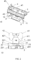
- FIG. 1 illustrates an electronic component according to an embodiment of the present invention.
- the electronic component includes at least an electric discharge protection element 1, a sensor device 2, and a carrier 3, but may contain additional elements not shown.
- the electronic component is shown in a perspective view in diagram a), in a side cut along line B - B' in diagram b), in a top view in diagram c), and in a side view in diagram d).
- the protection element 1 and the sensor device 2 are arranged on a front side of the carrier 3.
- the protection element 1 has the shape of a bridging structure that is arranged to bridge the sensor device 2.
- the protection element 1 contains two terminals 11 and 12 resting on the carrier 3.
- the bridging structure further includes two vertical portions 14 and 15, and a horizontal portion 13.
- the protection element 1 is a single piece made from a metal or any other electrically conducting material, and preferably is punched and bent into its present shape.
- the sensor device 2 is a packaged sensor chip 21 containing the sensor chip 21 and a package 22 in from of an encapsulation.
- the sensor chip 2 is arranged on a leadframe. Portions of the leadframe build contact pads 231 that are exposed at a bottom face of the sensor device 2 and as such face the carrier 3. In addition, portions of these contact pads 231 are exposed from side walls of the package 22 as can be seen in diagrams 1a) and 1b).
- the package 22 comprises an access opening 221 in form of a recess in a top surface of the package 22 for granting access to the sensor chip 2, and in particular for granting access to a sensitive element that is exposed from the package 22 by means of the access opening 221.
- the protection element 1 is electrically connected to a ground contact 31 of the carrier 3, via a conductor 32. Hence, any electrical discharge trapped by the protection element 1 is drained to the ground contact 31.
- a horizontal portion 13 of the protection element 1 spans the sensor device 2, and in particular spans a part of the access opening 221, since the exposed sensor chip 21 including the sensing element is most endangered by an electrical discharge. As can be seen from diagram 1c) it is not the entire surface of the sensor device 2 that is covered by the horizontal portion 13 of the protection element 1. Instead, a width w1 of the horizontal portion 13 is less than a width w2 of the sensor device 2 which ensures that the exposed portion of the sensor chip 2 receives a sufficient amount of the medium to be measured. Preferably, between a third and half of the top surface/footprint of the sensor device 2 is spanned by the protection element 1.
- the protection element 1 is arranged distant from the sensor device 2.
- a distance md which reflects a distance between a side wall of the sensor device 2 and the portion of the protection element 1 facing this side wall is equal to or less than 10 mm to prevent a direct discharge into the sensor device 2 on the one hand, and preferably is equal to or more than 0,05 mm, in order to prevent an arc-over on the one hand.
- the protection element 1 exceeds the sensor device 2 in height as can be derived from diagrams 1a) and 1b).
- a minimum height distance mh between the protection element 1 and the sensor device 2 is 1 mm.
- the contact pads 231 are arranged at an edge E1 of the sensor device 2 that does not face a terminal 11, 12 of the protection element 1.
- electrical connections - also referred to as solder joints in this context - between the carrier 3 and the contact pads 231 remain inspectable, and in particular optically inspectable.
- the sensor device 2 may comprise further contact pads 231 and solder joints at the opposed edge E2 which are optically inspectable in the same manner.
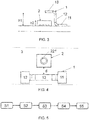
- FIG. 2 illustrates an electrical component according to an embodiment of the present invention.
- Diagram 2a) illustrates its perspective view
- diagram 2b) shows the electronic component in a lateral cut.
- the basic elements such as the protection element 1, the sensor device 2 and the carrier 3 may be identical to the ones shown in FIG. 1 , or may be of different shape and/or arrangement.
- the present electronic component includes a housing 4, e.g. made from plastics, only a portion of which housing 4 is shown, and which housing 4 shall protect the sensor device 2 and possibly any other elements arranged on the carrier 3.
- the housing 4 has two bars 41 and 42 forming an opening 43 there between.
- the bridge structured protection element 1 reaches into the opening 43, in particular with its horizontal portion 13, a top surface of which remains exposed to the outside world for trapping electrical discharges. Remainders of the opening not filled of the protection element 1 are dimensioned such that a sufficient amount of the medium reaches the sensor chip underneath.
- the two bars 41 and 42 each comprise an integrated clamp 411, 421, which clamp into the horizontal portion 13 of the protection element 1.
- the housing 4 and the carrier 3 are attached, such that the protection element 1 not only serves for draining an electric discharge but also serves for mounting the housing 4 to the carrier 3.
- the sensor device 2 comprises the sensor chip 21 arranged on a die pad 232 of a leadframe 32.
- contact portions 231 are made from the leadframe 23 and are connected to the sensor chip 2, e.g. by bond wires not shown.
- An encapsulation in form of a package 22 encloses portions of the sensor chip 21 and the leadframe 23.
- An access opening 221 in the package 22 provides access to a top surface of the sensor chip 21 including a sensitive element 211 being exposed through the access opening 221.
- the sensor chip 21 preferably is a semiconductor chip with a substrate, such as a silicon substrate, and a stack of material layers such as a CMOS layer stack on top of the substrate.
- the sensing element 211 is integrated into the sensor chip 21, e.g. is arranged in the stack of material layers in the present example.
- the sensing element 211 may be connected by means of at least two electrodes, such as interdigitated electrodes.
- the sensing element 211 may cover the electrodes.
- FIG. 3 illustrates an electrical component in a side cut according to an embodiment of the present invention.
- the present protection element 1 is not of a bridge shape but rather of a rod shape including a single terminal 11 only.
- a vertical portion 12 holds a horizontal portion 13 reaching into a space above the sensor device 2 for providing an effective discharge protection.
- a height h1 of the protection element 1 exceeds a height h2 of the sensor device 2.
- the protection element 1 is arranged separate from the sensor device 2.
- the single terminal 11 in combination with the rest of the protection element 1 is configured in its dimension and / or weight such that a center of gravity of the protection element is configured to make the protection element 1 remain in an upright position after being placed on the carrier 3 for surface mounting.
- the overall shape of the protection element in this embodiment may be considered as a step.
- FIG. 4 illustrates an electrical component not in accordance with the present invention in a top view.
- the protection element 1 again is bridge shaped such as in FIG. 1
- the protection element 1 now is arranged next to the sensor device 2, in particular at a distance d from the sensor device 2. This arrangement also provides an effective protection from an electric discharge.
- a housing (not shown) may be attached to the protection element 1 in the same manner as introduced with respect to FIG. 2 .
- FIG. 5 illustrates a method for manufacturing an electronic component according to an embodiment of the present invention.
- a sensor device is provided, the sensor device including contact pads.
- an electrostatic discharge protection element is provided, the protection element including at least one terminal.
- the sensor device is arranged on a carrier with the contact pads facing the carrier.
- the protection element is arranged on the carrier with the terminal facing the carrier.
- the contact pads and the at least one terminal are reflow soldered in a common reflow soldering step.
- Steps S1 and S2 can be interchanged in order.
- Steps S3 and S4 can be interchanged in order.
- Steps S1 and S3 can be performed in sequence, followed by steps S2 and S4.
- Steps S2 and S4 can be performed in sequence, followed by steps S1 and S3.
- the carrier is provided prepared, by having attached solder paste to the contact pads of the carrier the protection element and the sensor device are to be deposited on with their corresponding contact pads and terminals.
- a placement of the sensor device and the protection element onto the carrier includes a placement onto the solder paste.
- the common reflow soldering step may then include a heating of the solder paste for generating a sound electrical connection between the carrier and the sensor device and between the carrier and the protection element.
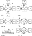
- FIGs. 6 to 10 each shows an electrical component in a top view, according to embodiments of the present invention.
- the protection element 1 is shaped as a bridging structure bridging a sensor device 2.
- the sensor device 2 preferably is a packaged sensor chip 21, but could take any other form of sensor device 2, too.
- the protection element 1 of FIG. 6 has four terminals 11, 12, 16 and 17 resting on the carrier. Accordingly, four vertical portions 14, 15, 18 and 19 are provided in the bridging structure, as well as a cross-shaped horizontal portion 13. This embodiment provides for an excellent mechanical stability.
- the protection element 1 of FIG. 7 has three terminals 11, 12 and 16 resting on the carrier. Accordingly, three vertical portions 14, 15, and 18 are provided in the bridging structure, as well as a T-shaped horizontal portion 13. This embodiment also provides for an excellent mechanical stability.
- the protection element 1 of FIG. 8 has two terminals 11, 12.
- the present horizontal portion 13 has cross-like extensions as such providing a bigger coverage of the sensor device 2 and as such providing an even better electric discharge protection.
- the protection element 1 of FIG. 9 has two terminals 11, 12, and a ring-shaped horizontal portion 13. Through the ring-shaped horizontal portion 13 an excellent access is provided to the sensor chip 21 for the medium to be measured, while at the same time the increased area of the ring-shaped horizontal portion 13 provides an excellent coverage of the sensor device 2 and as such provides an excellent electric discharge protection.
- the protection element 1 is identical to the protection element 1 of FIG. 9 . However, its orientation is different with respect to the sensor device 2. While in the embodiment of FIG. 9 , the basic orientation of the protection element 1 is in parallel to the edges of the sensor device 2 with its rectangular footprint, the protection element 1 of FIG. 10 is aligned diagonally across the sensor device 1. This orientation may also be implemented for any other shape of protection element 1.
- the protection element 1 is a single piece made from a metal or any other electrically conducting material, and preferably is punched and bent into its present shape.
- FIG. 11 illustrates an electrical component in a side cut, according to an embodiment of the present invention.
- the sensor device is represented by a sensor chip 21 with a sensing element 211 of the sensor chip 21 facing the carrier 3.
- the sensor chip 21 is flip-chip mounted onto the carrier 3 by means of e.g. solder balls 31. Access is granted to the sensing element 211 from side-ways - as indicated by the arrow - through a gap between the sensor chip 21 and the carrier 3.
- the protection element 1 bridges the sensor chip 2.
Landscapes
- Chemical & Material Sciences (AREA)
- Engineering & Computer Science (AREA)
- Physics & Mathematics (AREA)
- General Physics & Mathematics (AREA)
- Health & Medical Sciences (AREA)
- Life Sciences & Earth Sciences (AREA)
- Power Engineering (AREA)
- Immunology (AREA)
- Pathology (AREA)
- Analytical Chemistry (AREA)
- Biochemistry (AREA)
- General Health & Medical Sciences (AREA)
- Condensed Matter Physics & Semiconductors (AREA)
- Computer Hardware Design (AREA)
- Microelectronics & Electronic Packaging (AREA)
- Medicinal Chemistry (AREA)
- Food Science & Technology (AREA)
- Combustion & Propulsion (AREA)
- Chemical Kinetics & Catalysis (AREA)
- Electrochemistry (AREA)
- Pressure Sensors (AREA)
- Investigating Or Analyzing Materials By The Use Of Electric Means (AREA)
- Structures For Mounting Electric Components On Printed Circuit Boards (AREA)
Description
- The present idea refers to an electronic component and to a method for manufacturing an electronic component.
- Subject to the application, sensors tend to be integrated into sensor chips in today's world of miniaturization. This kind of manufacturing is beneficial in that the size of a sensor device can significantly be reduced compared to a discrete type sensor and a sensing element of such a sensor can be arranged next to electronic circuitry integrated into the very same sensor chip which circuitry may include functions acting on a signal delivered by the sensing element such as amplification, evaluation, etc.
-
US 5,407,854 provides methods, apparatus and chip fabrication techniques which provide electrostatic discharge (ESD) protection to ion-sensitive field effect transistor (ISFET) based devices used to selectively measure ions in a liquid. An ESD protection circuit, made up of conventional protective elements, is integrated onto the same silicon chip on which the ISFET is formed, along with an interface that is in contact with the liquid being measured and which does not open up paths for D.C. leakage currents between the ISFET and the liquid. A capacitor structure is used as the interface between the protection circuit and the liquid sample. - It is a general object of the invention to provide an electronic component including a sensor device with an improved electrostatic discharge protection.
- An electronic component according to the features of
claim 1 comprises a sensor device which sensor device comprises a sensor chip. The sensor chip preferably is a semiconductor chip comprising a semiconductor substrate such as a silicon substrate, and preferably comprising a sensing element, for example sensitive to one or more of a chemical analyte, humidity, a flow of a fluid, a pressure, light or temperature. The sensor chip may, or may not comprise integrated circuitry connected to the sensing element. - The sensor device may in one embodiment consist of the sensor chip, while in a different embodiment, the sensor device may in addition to the sensor chip comprise a package, such that the sensor device is represented by a packaged sensor chip. In a further embodiment the sensor device may comprise the sensor chip and additionally a cap substrate, for example. Preferably, and in particular in case the sensor chip is embodied for sensing an environmental measure such as humidity, a gas or pressure, the electronic component provides an access opening for allowing the medium to be measured to access the sensing element.
- The sensor device is arranged on a carrier. The carrier supports the sensor device, and possibly one or more other elements, such as an IC, discrete electrical elements, a plug, etc. The carrier may be one of a printed circuit board, either in a non-flexible or in a flexible form, a ceramic circuit board, or a different kind of a circuit board allowing the elements carried to be electrically interconnected.
- The sensor device - and in particular its sensor chip - may be exposed to an electrostatic discharge from the environment which may damage the sensor chip. In order to prevent such damage, an electric discharge protection element - in short: protection element - is arranged on the carrier. This protection element provides for an effective protection of the sensor chip from such electric discharge.
- In particular, if the sensor device itself does not include any electric discharge protection, the present approach allows for a still effective protection without the necessity to amend the design of the sensor device, and in particular the sensor chip. Hence, in one embodiment the protection element can be considered as a retrofit solution for protecting a sensor device originally lacking of an electric discharge protection.
- In a very preferred embodiment, the protection element is an electrically conductive structure, and in particular is a metallic structure. The protection element may be punched from a sheet of metal, and be folded thereafter to the desired final shape. The material of the protection element in one embodiment is tinned bronze.
- The protection element is physically separated from the sensor chip, and is also separated from the sensor device, such that there is no mechanical link there between other than via the carrier, of course. By this means, an efficient protection is realized by allowing an electric discharge being trapped by the protection element and being electrically isolated from the sensor chip. Preferably, a minimum distance between the protection element and the sensor device is 0.1 mm. This is beneficial in preventing flash-arcs.
- In case of the carrier being a circuit board comprising circuit paths, it is preferred that the circuit board also comprises a contact, and preferably a contact pad for a ground connection, and preferably for ground connecting the electronic component. The protection element preferably is electrically connected to this contact for draining any electric discharge trapped to ground. The circuit board may include an electrically conducting path between the ground contact and the protection element.
- In a preferred embodiment, the protection element exceeds the sensor device in height. Hence, the protection element is more attractive to trap an electric discharge than the sensor chip and/or the sensor device, respectively.
- In one alternative, the protection element comprises, a rod including a single terminal mounted on the carrier. Such protection element includes a portion extending into a space above the sensor device.
- In a different alternative, the protection element comprises a bridging structure including at least two, and preferably one of exactly two, three or four terminals resting on the carrier. Such protection element spans the sensor device at a distance. Such arrangement favors the trapping of electrical discharges. In addition, such protection element offers an enhanced mechanical stability given that the at least two of its terminals rest on the carrier. In a different embodiment, the bridging structure not only spans the sensor device but also one or more other chips in case such chips being present on the carrier.
- In a preferred embodiment, the sensor device is configured to sense a parameter of the environment, such as a flow of a fluid, light, temperature, gas, humidity, or pressure. In such example, a sensing element may be arranged on or integrated at a front side of the sensor chip which front side faces away from the carrier when the sensor chip is mounted onto the carrier.
- In many of the above applications, the sensing element requires an access to the environment for performing a sensing of the desired environmental variable. If in such case the sensor device comprises a package in addition to the sensor chip, the package preferably includes an access opening for allowing access to the sensing element. Preferably, the package of the sensor device protects the sensor chip from mechanical impact and/or light, and may seal the chip against an undesired impact of liquids or gases. In a preferred embodiment, the package may cover at least parts of the sensor chip in form of an encapsulation, e.g. in form of a mould compound. The material used may preferably be a resist, in particular a dry resist, for example SU-8. Or, the package may be an element formed separate from the chip and may be attached to the chip later on, for example, by gluing, bonding, etc. Here, the package may be a siliconon-insulator, or other semiconducting layer arrangement. The package may be made from one of a semiconductor, silicon, silicon and a silicon-oxide coating, silicon and a solderable coating, ceramic, ceramic and a silicon-oxide coating, ceramic and a solderable coating, glass, glass and a silicon-oxide coating, glass and a solderable coating, metal, metal and a solderable coating, dielectric material and a polymer.
- In such sensor device, the sensor chip typically is arranged on a support such as a leadframe, which leadframe includes a die pad for arranging the sensor chip on, and contact pads electrically connected to the sensor chip, e.g. by means of bond wires. The encapsulation partly encapsulates the chip except for the access opening, and partly encapsulates the leadframe, e.g. except for the contact pads and/or the die pads. The access opening may take the form of a recess in the package thereby exposing the sensitive element to the outside world. If in such case the protection element has the shape of a bridging structure and at least partly bridges the sensor device, it is desired that the bridging structure is designed in geometry and arranged relative to the sensor device such that on the one hand an effective electric discharge protection is realized, and that on the other hand a sensing function of the sensor chip is not impaired by the protection element. In a preferred embodiment, the bridging structure spans an area of a top surface of the sensor device that is between a third and half of the entire top surface of the sensor device.
- Preferably, the sensor device has a rectangular footprint owed to a typical rectangular footprint of the sensor chip diced out of a wafer. The sensor device preferably has contact pads exposed at least at a bottom surface of the sensor device, and preferably at edges of the sensor device. In case the sensor device only provides contact pads along two opposing edges of its footprint - also referred to as first pair of edges - such sensor device may also be referred to as DFN (Dual-Flat No-Leads). In case the sensor device provides contact pads along all edges of its footprint such sensor device may also be referred to as QFN (Quad-Flat No-Leads).
- It is preferred, that such sensor device is SMD-mounted (Surface Mounted Device) to the carrier. The carrier shows contact pads being prepared with a contact material such as a solder paste prior to the sensor device being placed onto the carrier. After having placed the sensor device onto the carrier with its contact pads being aligned with the contact pads of the carrier and hence being deposited onto the solder paste, the electrical connections are established by heating the solder paste. In such scenario, it is preferred that solder joints remain optically inspectable, and preferably automatically optically inspectable, for verifying the electrical connection between the sensor device and the carrier.
- Taking the desire for an automated optical inspection of the electrical connections into account, it is preferred that the bridging structure is arranged on the carrier such that it does not affect the automated optical inspection of the electrical connections. Hence, in case of a DFN package with contact pads arranged along the first pair of edges, it is preferred that the terminals of the bridging structure are arranged facing the sensor device at a second pair of opposed edges of its rectangular footprint. However, in a different embodiment, the sensor device may be represented by a QFN package even if optical inspection accessibility to two edges of the sensor device is limited owed to the arrangement of the bridging structure protection element.
- While in one embodiment of the present invention - and provided the sensor chip has a rectangular footprint - the bridging structure is arranged to bridge the sensor device in parallel to one of a longitudinal or lateral extension of the sensor chip, in a different embodiment, the bridging structure is arranged to bridge the sensor device diagonally.
- In a preferred embodiment, the protection element is a multi-use element. The protection element not only serves as an electric discharge protection element, but can also be used for mounting a housing to the carrier. In particular when the protection element is embodied as a bridging structure, the protection element in combination with a mounting element of the housing provides for a fixture for the housing. The mounting element on the housing side may include one or more clamps which are clamped to the protection element thereby securing the housing to the carrier. The housing may protect the sensor device and/or any further electronics from mechanical and/or fluid impact. The housing preferably is made from plastics and in a mounted state is clamped to the bridging structure.
- Preferably, the electronic component is used in an automotive application.
- According to another aspect of the present invention, a method is provided for manufacturing an electronic component. A sensor device is provided including contact pads as well as an electrostatic discharge protection element including at least one terminal. This order in providing the sensor device and the protection element is arbitrary and may be reversed.
- The sensor device is arranged on a carrier with the contact pads facing the carrier, and the protection element is arranged on the carrier with its one or more terminals facing the carrier. Again, this order is arbitrary and may be reversed.
- Once both the sensor device and the protection element are arranged on the carrier, a common reflow soldering step is applied to both the sensor device and the protection element. The common reflow soldering step in particular may comprise a heating of a solder paste arranged between the contact pads / terminals of the sensor device and the protection element on the one hand and contact pads of the carrier on the other hand, thereby electrically and/or mechanically connecting the sensor device and the protection element to the carrier.
- This present idea results in an effective protection of the sensor chip including any circuitry from an electric discharge.
- Other advantageous embodiments are listed in the dependent claims as well as in the description below.
- The embodiments defined above and further embodiments, features and advantages of the present invention can also be derived from the examples of embodiments to be described hereinafter in connection with the drawings in which the figures illustrate:
-
FIG. 1 an electrical component according to an embodiment of the present invention, in diagram a) in a perspective view, in diagram b) in a side cut, in diagram c) in a top view, and in diagram d) in a side view; -
FIG. 2 an electrical component according to an embodiment of the present invention, in diagram a) in a perspective view, and in diagram b) in a lateral cut; -
FIG. 3 an electrical component in a side cut, according to an embodiment of the present invention; -
FIG. 4 an electrical component not encompassed by the present invention is presented in a top view; and -
FIG. 5 a method for manufacturing an electronic component according to an embodiment of the present invention; -
FIGs. 6 to 10 each an electrical component in a top view, according to embodiments of the present invention; and -
FIG. 11 an electrical component in a side cut, according to an embodiment of the present invention. -
FIG. 1 illustrates an electronic component according to an embodiment of the present invention. The electronic component includes at least an electricdischarge protection element 1, asensor device 2, and acarrier 3, but may contain additional elements not shown. The electronic component is shown in a perspective view in diagram a), in a side cut along line B - B' in diagram b), in a top view in diagram c), and in a side view in diagram d). - The
carrier 3, for example, is a printed circuit board. Theprotection element 1 and thesensor device 2 are arranged on a front side of thecarrier 3. In the present embodiment, theprotection element 1 has the shape of a bridging structure that is arranged to bridge thesensor device 2. Theprotection element 1 contains twoterminals carrier 3. The bridging structure further includes twovertical portions horizontal portion 13. Theprotection element 1 is a single piece made from a metal or any other electrically conducting material, and preferably is punched and bent into its present shape. - The
sensor device 2 is a packagedsensor chip 21 containing thesensor chip 21 and apackage 22 in from of an encapsulation. Thesensor chip 2 is arranged on a leadframe. Portions of the leadframebuild contact pads 231 that are exposed at a bottom face of thesensor device 2 and as such face thecarrier 3. In addition, portions of thesecontact pads 231 are exposed from side walls of thepackage 22 as can be seen in diagrams 1a) and 1b). Thepackage 22 comprises an access opening 221 in form of a recess in a top surface of thepackage 22 for granting access to thesensor chip 2, and in particular for granting access to a sensitive element that is exposed from thepackage 22 by means of theaccess opening 221. - As can be derived from diagram 1b), the
protection element 1 is electrically connected to aground contact 31 of thecarrier 3, via aconductor 32. Hence, any electrical discharge trapped by theprotection element 1 is drained to theground contact 31. - A
horizontal portion 13 of theprotection element 1 spans thesensor device 2, and in particular spans a part of the access opening 221, since the exposedsensor chip 21 including the sensing element is most endangered by an electrical discharge. As can be seen from diagram 1c) it is not the entire surface of thesensor device 2 that is covered by thehorizontal portion 13 of theprotection element 1. Instead, a width w1 of thehorizontal portion 13 is less than a width w2 of thesensor device 2 which ensures that the exposed portion of thesensor chip 2 receives a sufficient amount of the medium to be measured. Preferably, between a third and half of the top surface/footprint of thesensor device 2 is spanned by theprotection element 1. - As can be seen from diagrams 1a) and 1b), the
protection element 1 is arranged distant from thesensor device 2. Preferably, a distance md, which reflects a distance between a side wall of thesensor device 2 and the portion of theprotection element 1 facing this side wall is equal to or less than 10 mm to prevent a direct discharge into thesensor device 2 on the one hand, and preferably is equal to or more than 0,05 mm, in order to prevent an arc-over on the one hand. - When it comes to a height relation between the
sensor device 2 and theprotection element 1, it is preferred that theprotection element 1 exceeds thesensor device 2 in height as can be derived from diagrams 1a) and 1b). In particular, a minimum height distance mh between theprotection element 1 and thesensor device 2 is 1 mm. - As can be derived from diagram 1a), the
contact pads 231 are arranged at an edge E1 of thesensor device 2 that does not face a terminal 11, 12 of theprotection element 1. Hence, electrical connections - also referred to as solder joints in this context - between thecarrier 3 and thecontact pads 231 remain inspectable, and in particular optically inspectable. Thesensor device 2 may comprisefurther contact pads 231 and solder joints at the opposed edge E2 which are optically inspectable in the same manner. -
FIG. 2 illustrates an electrical component according to an embodiment of the present invention. Diagram 2a) illustrates its perspective view, while diagram 2b) shows the electronic component in a lateral cut. The basic elements such as theprotection element 1, thesensor device 2 and thecarrier 3 may be identical to the ones shown inFIG. 1 , or may be of different shape and/or arrangement. In addition, the present electronic component includes ahousing 4, e.g. made from plastics, only a portion of whichhousing 4 is shown, and whichhousing 4 shall protect thesensor device 2 and possibly any other elements arranged on thecarrier 3. - The
housing 4 has twobars opening 43 there between. The bridge structuredprotection element 1 reaches into theopening 43, in particular with itshorizontal portion 13, a top surface of which remains exposed to the outside world for trapping electrical discharges. Remainders of the opening not filled of theprotection element 1 are dimensioned such that a sufficient amount of the medium reaches the sensor chip underneath. - The two
bars integrated clamp horizontal portion 13 of theprotection element 1. Hence, thehousing 4 and thecarrier 3 are attached, such that theprotection element 1 not only serves for draining an electric discharge but also serves for mounting thehousing 4 to thecarrier 3. - According to the cut view shown in diagram 2b), the
sensor device 2 comprises thesensor chip 21 arranged on adie pad 232 of aleadframe 32. In addition,contact portions 231 are made from theleadframe 23 and are connected to thesensor chip 2, e.g. by bond wires not shown. An encapsulation in form of apackage 22 encloses portions of thesensor chip 21 and theleadframe 23. An access opening 221 in thepackage 22 provides access to a top surface of thesensor chip 21 including asensitive element 211 being exposed through theaccess opening 221. - The
sensor chip 21 preferably is a semiconductor chip with a substrate, such as a silicon substrate, and a stack of material layers such as a CMOS layer stack on top of the substrate. Thesensing element 211 is integrated into thesensor chip 21, e.g. is arranged in the stack of material layers in the present example. Thesensing element 211 may be connected by means of at least two electrodes, such as interdigitated electrodes. Thesensing element 211 may cover the electrodes. -
FIG. 3 illustrates an electrical component in a side cut according to an embodiment of the present invention. In contrast to theprotection element 1 introduced inFIG. 1 , thepresent protection element 1 is not of a bridge shape but rather of a rod shape including asingle terminal 11 only. In addition, avertical portion 12 holds ahorizontal portion 13 reaching into a space above thesensor device 2 for providing an effective discharge protection. Notably, a height h1 of theprotection element 1 exceeds a height h2 of thesensor device 2. Theprotection element 1 is arranged separate from thesensor device 2. It is preferred, that thesingle terminal 11 in combination with the rest of theprotection element 1 is configured in its dimension and / or weight such that a center of gravity of the protection element is configured to make theprotection element 1 remain in an upright position after being placed on thecarrier 3 for surface mounting. The overall shape of the protection element in this embodiment may be considered as a step. -
FIG. 4 illustrates an electrical component not in accordance with the present invention in a top view. Although theprotection element 1 again is bridge shaped such as inFIG. 1 , theprotection element 1 now is arranged next to thesensor device 2, in particular at a distance d from thesensor device 2. This arrangement also provides an effective protection from an electric discharge. A housing (not shown) may be attached to theprotection element 1 in the same manner as introduced with respect toFIG. 2 . -
FIG. 5 illustrates a method for manufacturing an electronic component according to an embodiment of the present invention. In step S1, a sensor device is provided, the sensor device including contact pads. In step S2, an electrostatic discharge protection element is provided, the protection element including at least one terminal. In step S3, the sensor device is arranged on a carrier with the contact pads facing the carrier. In step S4, the protection element is arranged on the carrier with the terminal facing the carrier. In step S5, the contact pads and the at least one terminal are reflow soldered in a common reflow soldering step. - Steps S1 and S2 can be interchanged in order. Steps S3 and S4 can be interchanged in order. Steps S1 and S3 can be performed in sequence, followed by steps S2 and S4. Steps S2 and S4 can be performed in sequence, followed by steps S1 and S3.
- In a preferred embodiment, the carrier is provided prepared, by having attached solder paste to the contact pads of the carrier the protection element and the sensor device are to be deposited on with their corresponding contact pads and terminals. Hence, a placement of the sensor device and the protection element onto the carrier includes a placement onto the solder paste. The common reflow soldering step may then include a heating of the solder paste for generating a sound electrical connection between the carrier and the sensor device and between the carrier and the protection element.
-
FIGs. 6 to 10 each shows an electrical component in a top view, according to embodiments of the present invention. In each of these embodiments, theprotection element 1 is shaped as a bridging structure bridging asensor device 2. Thesensor device 2 preferably is a packagedsensor chip 21, but could take any other form ofsensor device 2, too. - Instead of two
terminals protection element 1 ofFIG. 6 has fourterminals vertical portions horizontal portion 13. This embodiment provides for an excellent mechanical stability. - The
protection element 1 ofFIG. 7 has threeterminals vertical portions horizontal portion 13. This embodiment also provides for an excellent mechanical stability. - The
protection element 1 ofFIG. 8 has twoterminals horizontal portion 13 has cross-like extensions as such providing a bigger coverage of thesensor device 2 and as such providing an even better electric discharge protection. - The
protection element 1 ofFIG. 9 has twoterminals horizontal portion 13. Through the ring-shapedhorizontal portion 13 an excellent access is provided to thesensor chip 21 for the medium to be measured, while at the same time the increased area of the ring-shapedhorizontal portion 13 provides an excellent coverage of thesensor device 2 and as such provides an excellent electric discharge protection. - In the embodiment of
FIG. 10 , theprotection element 1 is identical to theprotection element 1 ofFIG. 9 . However, its orientation is different with respect to thesensor device 2. While in the embodiment ofFIG. 9 , the basic orientation of theprotection element 1 is in parallel to the edges of thesensor device 2 with its rectangular footprint, theprotection element 1 ofFIG. 10 is aligned diagonally across thesensor device 1. This orientation may also be implemented for any other shape ofprotection element 1. - Again, it is preferred that for any of the previous embodiments the
protection element 1 is a single piece made from a metal or any other electrically conducting material, and preferably is punched and bent into its present shape. -
FIG. 11 illustrates an electrical component in a side cut, according to an embodiment of the present invention. In this embodiment, the sensor device is represented by asensor chip 21 with asensing element 211 of thesensor chip 21 facing thecarrier 3. Hence, thesensor chip 21 is flip-chip mounted onto thecarrier 3 by means ofe.g. solder balls 31. Access is granted to thesensing element 211 from side-ways - as indicated by the arrow - through a gap between thesensor chip 21 and thecarrier 3. Theprotection element 1 bridges thesensor chip 2. - While there are shown and described presently preferred embodiments of the invention, it is to be distinctly understood that the invention is not limited thereto but may be otherwise variously embodied and practiced within the scope of the following claims.
Claims (14)
- Electronic component, comprising
a carrier (3),
a sensor device (2) mounted on the carrier (3), which sensor device (2) comprises a sensor chip (21),
an electrostatic discharge protection element (1) for protecting the sensor chip (21) from an electrostatic discharge, which protection element (1) is mounted on the carrier (3),
wherein the protection element (1) is physically separated from the sensor device (2),
wherein the protection element (1) comprises a bridging structure including at least two terminals (11,12) resting on the carrier (3) and wherein the protection element (1) is arranged to bridge the sensor device (2), or
wherein the protection element (1) comprises a rod including a single terminal (11) mounted on the carrier (3) and wherein the rod includes a portion (13) extending into a space above the sensor device (2). - Electronic component according to claim 1,
wherein a distance (md) between the protection element (1) and the sensor device (2) is equal to or more than 0.05 mm,
in particular wherein the distance (md) between the protection element (1) and the sensor device (2) is equal to or less than 10 mm. - Electronic component according to claim 1 or claim 2,
wherein the protection element (1) exceeds the sensor device (2) in height, and
in particular wherein a minimum height distance (mh) between the protection element (1) and the sensor device (2) is 1 mm. - Electronic component according to any of the previous claims,
wherein the protection element (1) includes exactly two terminals (11,12) resting on the carrier (3),
in particular wherein the protection element (1) includes exactly three terminals (11,12) resting on the carrier (3),
in particular wherein the protection element (1) includes exactly four terminals (11,12) resting on the carrier (3). - Electronic component according to claim 4,
wherein the protection element (1) has two terminals (11,12),
wherein the sensor device (2) has a rectangular footprint with a first and a second pair of opposed edges,
wherein the sensor device (2) comprises contact pads (231) arranged along the first pair of opposed edges of its rectangular footprint,
wherein the terminals (11,12) of the protection element (1) are arranged facing the sensor device (2) at the second pair of opposed edges of its rectangular footprint. - Electronic component according to any one of the preceding claims,
wherein the sensor device (2) comprises a package (22),
wherein the sensor chip (21) comprises a sensing element (211) arranged on or integrated at a front side of the sensor chip (21) facing away from the carrier (3)
wherein the package (22) comprises an access opening (221) for providing access to the sensing element (211) from the outside of the sensor chip (2), and
wherein the protection element (1) is arranged to bridge at least a part of the access opening (221). - Electronic component according to any one of the preceding claims,
wherein the sensor chip (21) comprises a sensing element (211) arranged on or integrated at a front side of the sensor chip (21) facing the carrier (3),
wherein an access opening is provided between the sensor chip (21) and the carrier (3) for granting access to the sensing element (211) from the outside of the sensor chip (2), and
wherein the protection element (1) is arranged to bridge the sensor chip (21). - Electronic component according to any of the preceding claims,
wherein the single terminal (11) is configured in its dimension and / or weight that the protection element (1) remains in an upright position after being placed on the carrier (3) for surface mounting - Electronic component according to any of the preceding claims,
wherein the protection element (1) is of a step-like shape. - Electronic component according to any one of the preceding claims,
wherein the carrier (3) is a circuit board, and in particular a printed circuit board,
wherein the carrier (3) comprises a contact (31) for a ground connection, and
wherein the protection element (1) is electrically connected to the contact (31) for ground connection. - Electronic component according to any one of the preceding claims,
comprising a housing (4) for protecting the sensor device (2),
wherein the housing (4) comprises one or more mounting elements, and in particular one or more clamps (411, 421), and
wherein in a mounted position the housing (4) is mounted to the carrier (3) via at least one of the one or more mounting elements, and in particular via at least one of the one or more clamps (411, 421) mounting the protection element (1). - Electronic component according to any of the previous claims,
wherein the protection element (1) and the sensor device (2) are reflow soldered onto the carrier (3) . - Method for manufacturing an electronic component, comprising
providing a sensor device (2) including contact pads (231),
providing an electrostatic discharge protection element (1) including at least one terminal (11), wherein the protection element (1) comprises a bridging structure including at least two terminals (11,12) resting on the carrier (3) and wherein the protection element (1) is arranged to bridge the sensor device (2), or wherein the protection element (1) comprises a rod including a single terminal (11) mounted on the carrier (3) and wherein the rod includes a portion (13) extending into a space above the sensor device (2),
arranging the sensor device (2) on a carrier (3) with the contact pads facing the carrier (3),
arranging the protection element (1) on the carrier (3) physically separate from the sensor device (2) and with the at least one terminal (11) facing the carrier (3),
reflow soldering the contact pads (231) and the at least one terminal (11) in a common reflow soldering step. - Method according to claim 13, comprising
providing the sensor device (2) with a rectangular footprint with a first and a second pair of opposed edges,
providing the sensor device (2) with contact pads (231) arranged along the first pair of opposed edges of its rectangular footprint,
providing the protection element (1) in form of a bridging structure including two terminals (11, 12),
arranging the bridging structure on the carrier (3) with its terminals (11,12) facing the sensor device (2) at the second pair of opposed edges of its rectangular footprint, and
preferably automatically optically inspecting solder connections between the contact pads (231) and the carrier (3) created in the reflow soldering step.
Priority Applications (4)
| Application Number | Priority Date | Filing Date | Title |
|---|---|---|---|
| KR1020187022867A KR20180112787A (en) | 2016-02-11 | 2017-02-03 | Sensor chip with electrostatic discharge protection element |
| US16/074,979 US11022590B2 (en) | 2016-02-11 | 2017-02-03 | Electronic component including sensor device and method of manufacturing same |
| PCT/EP2017/052404 WO2017137325A1 (en) | 2016-02-11 | 2017-02-03 | Sensor chip with electrostatic discharge protection element |
| CN201780010774.4A CN108603873B (en) | 2016-02-11 | 2017-02-03 | Sensor chip with electrostatic discharge protection element |
Applications Claiming Priority (1)
| Application Number | Priority Date | Filing Date | Title |
|---|---|---|---|
| EP16155356.5A EP3206027B1 (en) | 2016-02-11 | 2016-02-11 | Sensor chip comprising electrostatic discharge protection element |
Publications (3)
| Publication Number | Publication Date |
|---|---|
| EP3206029A1 EP3206029A1 (en) | 2017-08-16 |
| EP3206029B1 true EP3206029B1 (en) | 2018-06-13 |
| EP3206029B8 EP3206029B8 (en) | 2018-08-08 |
Family
ID=55405134
Family Applications (2)
| Application Number | Title | Priority Date | Filing Date |
|---|---|---|---|
| EP16155356.5A Active EP3206027B1 (en) | 2016-02-11 | 2016-02-11 | Sensor chip comprising electrostatic discharge protection element |
| EP16163475.3A Active EP3206029B8 (en) | 2016-02-11 | 2016-04-01 | Sensor chip with electrostatic discharge protection element |
Family Applications Before (1)
| Application Number | Title | Priority Date | Filing Date |
|---|---|---|---|
| EP16155356.5A Active EP3206027B1 (en) | 2016-02-11 | 2016-02-11 | Sensor chip comprising electrostatic discharge protection element |
Country Status (5)
| Country | Link |
|---|---|
| US (1) | US11022590B2 (en) |
| EP (2) | EP3206027B1 (en) |
| KR (1) | KR20180112787A (en) |
| CN (1) | CN108603873B (en) |
| WO (1) | WO2017137325A1 (en) |
Families Citing this family (6)
| Publication number | Priority date | Publication date | Assignee | Title |
|---|---|---|---|---|
| DE202018100186U1 (en) | 2018-01-15 | 2018-01-26 | Sensirion Automotive Solutions Ag | Sensor module for air quality measurement |
| JP7052441B2 (en) * | 2018-03-13 | 2022-04-12 | 富士電機株式会社 | Sensor device |
| KR102562495B1 (en) * | 2018-08-31 | 2023-08-02 | 에이치엘만도 주식회사 | Apparatus for Non-contactive Sensor Having ESD Protection Structure |
| KR102553725B1 (en) * | 2018-08-31 | 2023-07-11 | 에이치엘만도 주식회사 | Apparatus for Non-contactive Sensor Having ESD Protection Structure |
| DE102021115816A1 (en) * | 2021-06-18 | 2022-12-22 | Polyic Gmbh & Co. Kg | Device for protection against electrostatic discharges in electronic components |
| EP4215908A1 (en) * | 2022-01-19 | 2023-07-26 | E+E Elektronik Ges.M.B.H. | Moisture sensor assembly |
Family Cites Families (18)
| Publication number | Priority date | Publication date | Assignee | Title |
|---|---|---|---|---|
| US5414284A (en) * | 1994-01-19 | 1995-05-09 | Baxter; Ronald D. | ESD Protection of ISFET sensors |
| US6940405B2 (en) * | 1996-05-30 | 2005-09-06 | Guardit Technologies Llc | Portable motion detector and alarm system and method |
| DE19901384A1 (en) * | 1999-01-15 | 2000-07-27 | Siemens Ag | Electronic component and use of a protective structure contained therein |
| CN100337325C (en) * | 2002-08-26 | 2007-09-12 | 日月光半导体制造股份有限公司 | Packaging baseplate having electrostatic discharge protection |
| TWI328776B (en) * | 2006-12-26 | 2010-08-11 | Egis Technology Inc | Sweep-type fingerprint sensing device and method of packaging the same |
| DE102007029720A1 (en) * | 2007-06-27 | 2009-01-08 | Robert Bosch Gmbh | Assembly with an ASIC and a housing for the ASIC |
| TW200939414A (en) * | 2008-03-14 | 2009-09-16 | Taiwan Ic Packaging Corp | Touch sensor having electrostatic discharge function |
| CN201629903U (en) | 2010-03-26 | 2010-11-10 | 华为终端有限公司 | Static discharging protection device and circuit board device |
| US8258012B2 (en) | 2010-05-14 | 2012-09-04 | Stats Chippac, Ltd. | Semiconductor device and method of forming discontinuous ESD protection layers between semiconductor die |
| GB2540904B (en) * | 2010-10-08 | 2017-05-24 | Dnae Group Holdings Ltd | Electrostatic discharge protection |
| EP2469270A1 (en) * | 2010-12-22 | 2012-06-27 | Sensirion AG | Wireless sensor device |
| CN202050071U (en) * | 2011-05-20 | 2011-11-23 | 达创科技(东莞)有限公司 | Electrostatic protection structure |
| JP5749566B2 (en) * | 2011-05-20 | 2015-07-15 | 株式会社堀場製作所 | ISFET sensor |
| CN203387770U (en) | 2013-05-23 | 2014-01-08 | 舒尔电子(苏州)有限公司 | Antistatic protection device, circuit board and electronic device |
| FR3014094B1 (en) * | 2013-11-29 | 2016-01-22 | Commissariat Energie Atomique | MICRO-FACTORY MECHANICAL SYSTEM (NEMS) WITH ADAPTATION RESISTORS |
| TWI540469B (en) * | 2014-04-01 | 2016-07-01 | 原相科技股份有限公司 | Electronic device with high electrostatic protection |
| US9147100B1 (en) * | 2014-05-09 | 2015-09-29 | Sunasic Technologies Inc. | Method for enhancing surface characteristics of a fingerprint sensor and structure made of the same |
| US10152146B2 (en) * | 2015-09-16 | 2018-12-11 | Microsoft Technology Licensing, Llc | Cosmetically hidden electrostatic discharge protection structures |
-
2016
- 2016-02-11 EP EP16155356.5A patent/EP3206027B1/en active Active
- 2016-04-01 EP EP16163475.3A patent/EP3206029B8/en active Active
-
2017
- 2017-02-03 KR KR1020187022867A patent/KR20180112787A/en not_active Application Discontinuation
- 2017-02-03 WO PCT/EP2017/052404 patent/WO2017137325A1/en active Application Filing
- 2017-02-03 US US16/074,979 patent/US11022590B2/en active Active
- 2017-02-03 CN CN201780010774.4A patent/CN108603873B/en active Active
Non-Patent Citations (1)
| Title |
|---|
| None * |
Also Published As
| Publication number | Publication date |
|---|---|
| WO2017137325A1 (en) | 2017-08-17 |
| EP3206029B8 (en) | 2018-08-08 |
| US20190041372A1 (en) | 2019-02-07 |
| CN108603873B (en) | 2021-08-27 |
| KR20180112787A (en) | 2018-10-12 |
| EP3206029A1 (en) | 2017-08-16 |
| EP3206027B1 (en) | 2019-09-11 |
| EP3206027A1 (en) | 2017-08-16 |
| CN108603873A (en) | 2018-09-28 |
| US11022590B2 (en) | 2021-06-01 |
Similar Documents
| Publication | Publication Date | Title |
|---|---|---|
| EP3206029B1 (en) | Sensor chip with electrostatic discharge protection element | |
| EP2342747B1 (en) | Integrated sensor including sensing and processing die mounted on opposite sides of package substrate | |
| KR101434321B1 (en) | Method for manufacturing a microelectromechanical component, and a microelectromechanical component | |
| CN100456428C (en) | Semiconductor device manufacturing method | |
| US7433197B2 (en) | Electronic module and method for sealing an electronic module | |
| KR101388946B1 (en) | Method for manufacturing a microelectromechanical component, and a microelectromechanical component | |
| KR100559062B1 (en) | Semiconductor device and its manufacturing method | |
| US20150001646A1 (en) | Pre-mold for a microphone assembly and method of producing the same | |
| CN103748457A (en) | Humidity sensor and method for manufacturing same | |
| US20100096712A1 (en) | Hermetic sealing and electrical contacting of a microelectromechanical structure, and microsystem (mems) produced therewith | |
| JP3173006U (en) | Sensor element | |
| EP2762865A1 (en) | Chemical sensor and method for manufacturing such a chemical sensor | |
| EP3601957B1 (en) | Sensor package | |
| EP2884242B1 (en) | Sensor Package And Manufacturing Method | |
| EP3292404B1 (en) | Sensor chip with electrostatic discharge protection element | |
| TW201724612A (en) | Lid structure and semiconductor device package including the same | |
| KR20190087528A (en) | Humidity sensor device | |
| US20240044856A1 (en) | Arrays of gas sensor device packages, and related methods | |
| JPH0491475A (en) | Semiconductor chip and semiconductor integrated circuit device using same | |
| JP2001174358A (en) | Sensor and its manufacturing method | |
| KR20120133618A (en) | Hermetic Package | |
| TW200527559A (en) | Ball grid array package and method for manufacturing the same |
Legal Events
| Date | Code | Title | Description |
|---|---|---|---|
| PUAI | Public reference made under article 153(3) epc to a published international application that has entered the european phase |
Free format text: ORIGINAL CODE: 0009012 |
|
| STAA | Information on the status of an ep patent application or granted ep patent |
Free format text: STATUS: THE APPLICATION HAS BEEN PUBLISHED |
|
| AK | Designated contracting states |
Kind code of ref document: A1 Designated state(s): AL AT BE BG CH CY CZ DE DK EE ES FI FR GB GR HR HU IE IS IT LI LT LU LV MC MK MT NL NO PL PT RO RS SE SI SK SM TR |
|
| AX | Request for extension of the european patent |
Extension state: BA ME |
|
| STAA | Information on the status of an ep patent application or granted ep patent |
Free format text: STATUS: REQUEST FOR EXAMINATION WAS MADE |
|
| 17P | Request for examination filed |
Effective date: 20170908 |
|
| RBV | Designated contracting states (corrected) |
Designated state(s): AL AT BE BG CH CY CZ DE DK EE ES FI FR GB GR HR HU IE IS IT LI LT LU LV MC MK MT NL NO PL PT RO RS SE SI SK SM TR |
|
| STAA | Information on the status of an ep patent application or granted ep patent |
Free format text: STATUS: EXAMINATION IS IN PROGRESS |
|
| 17Q | First examination report despatched |
Effective date: 20171124 |
|
| REG | Reference to a national code |
Ref country code: DE Ref legal event code: R079 Ref document number: 602016003452 Country of ref document: DE Free format text: PREVIOUS MAIN CLASS: G01N0033000000 Ipc: G01N0027120000 |
|
| RIC1 | Information provided on ipc code assigned before grant |
Ipc: G01N 27/12 20060101AFI20180124BHEP Ipc: H01L 27/02 20060101ALI20180124BHEP Ipc: G01N 33/00 20060101ALI20180124BHEP |
|
| GRAP | Despatch of communication of intention to grant a patent |
Free format text: ORIGINAL CODE: EPIDOSNIGR1 |
|
| STAA | Information on the status of an ep patent application or granted ep patent |
Free format text: STATUS: GRANT OF PATENT IS INTENDED |
|
| GRAS | Grant fee paid |
Free format text: ORIGINAL CODE: EPIDOSNIGR3 |
|
| INTG | Intention to grant announced |
Effective date: 20180313 |
|
| GRAA | (expected) grant |
Free format text: ORIGINAL CODE: 0009210 |
|
| STAA | Information on the status of an ep patent application or granted ep patent |
Free format text: STATUS: THE PATENT HAS BEEN GRANTED |
|
| RAP1 | Party data changed (applicant data changed or rights of an application transferred) |
Owner name: SENSIRON AUTOMOTIVE SOLUTIONS AG |
|
| AK | Designated contracting states |
Kind code of ref document: B1 Designated state(s): AL AT BE BG CH CY CZ DE DK EE ES FI FR GB GR HR HU IE IS IT LI LT LU LV MC MK MT NL NO PL PT RO RS SE SI SK SM TR |
|
| REG | Reference to a national code |
Ref country code: GB Ref legal event code: FG4D |
|
| REG | Reference to a national code |
Ref country code: CH Ref legal event code: EP Ref country code: AT Ref legal event code: REF Ref document number: 1009001 Country of ref document: AT Kind code of ref document: T Effective date: 20180615 |
|
| GRAT | Correction requested after decision to grant or after decision to maintain patent in amended form |
Free format text: ORIGINAL CODE: EPIDOSNCDEC |
|
| REG | Reference to a national code |
Ref country code: IE Ref legal event code: FG4D |
|
| REG | Reference to a national code |
Ref country code: DE Ref legal event code: R096 Ref document number: 602016003452 Country of ref document: DE |
|
| REG | Reference to a national code |
Ref country code: CH Ref legal event code: PK Free format text: BERICHTIGUNG B8 |
|
| REG | Reference to a national code |
Ref country code: NL Ref legal event code: MP Effective date: 20180613 |
|
| REG | Reference to a national code |
Ref country code: LT Ref legal event code: MG4D |
|
| PG25 | Lapsed in a contracting state [announced via postgrant information from national office to epo] |
Ref country code: BG Free format text: LAPSE BECAUSE OF FAILURE TO SUBMIT A TRANSLATION OF THE DESCRIPTION OR TO PAY THE FEE WITHIN THE PRESCRIBED TIME-LIMIT Effective date: 20180913 Ref country code: NO Free format text: LAPSE BECAUSE OF FAILURE TO SUBMIT A TRANSLATION OF THE DESCRIPTION OR TO PAY THE FEE WITHIN THE PRESCRIBED TIME-LIMIT Effective date: 20180913 Ref country code: LT Free format text: LAPSE BECAUSE OF FAILURE TO SUBMIT A TRANSLATION OF THE DESCRIPTION OR TO PAY THE FEE WITHIN THE PRESCRIBED TIME-LIMIT Effective date: 20180613 Ref country code: SE Free format text: LAPSE BECAUSE OF FAILURE TO SUBMIT A TRANSLATION OF THE DESCRIPTION OR TO PAY THE FEE WITHIN THE PRESCRIBED TIME-LIMIT Effective date: 20180613 Ref country code: CY Free format text: LAPSE BECAUSE OF FAILURE TO SUBMIT A TRANSLATION OF THE DESCRIPTION OR TO PAY THE FEE WITHIN THE PRESCRIBED TIME-LIMIT Effective date: 20180613 Ref country code: FI Free format text: LAPSE BECAUSE OF FAILURE TO SUBMIT A TRANSLATION OF THE DESCRIPTION OR TO PAY THE FEE WITHIN THE PRESCRIBED TIME-LIMIT Effective date: 20180613 |
|
| PG25 | Lapsed in a contracting state [announced via postgrant information from national office to epo] |
Ref country code: LV Free format text: LAPSE BECAUSE OF FAILURE TO SUBMIT A TRANSLATION OF THE DESCRIPTION OR TO PAY THE FEE WITHIN THE PRESCRIBED TIME-LIMIT Effective date: 20180613 Ref country code: HR Free format text: LAPSE BECAUSE OF FAILURE TO SUBMIT A TRANSLATION OF THE DESCRIPTION OR TO PAY THE FEE WITHIN THE PRESCRIBED TIME-LIMIT Effective date: 20180613 Ref country code: RS Free format text: LAPSE BECAUSE OF FAILURE TO SUBMIT A TRANSLATION OF THE DESCRIPTION OR TO PAY THE FEE WITHIN THE PRESCRIBED TIME-LIMIT Effective date: 20180613 Ref country code: GR Free format text: LAPSE BECAUSE OF FAILURE TO SUBMIT A TRANSLATION OF THE DESCRIPTION OR TO PAY THE FEE WITHIN THE PRESCRIBED TIME-LIMIT Effective date: 20180914 |
|
| REG | Reference to a national code |
Ref country code: AT Ref legal event code: MK05 Ref document number: 1009001 Country of ref document: AT Kind code of ref document: T Effective date: 20180613 |
|
| PG25 | Lapsed in a contracting state [announced via postgrant information from national office to epo] |
Ref country code: NL Free format text: LAPSE BECAUSE OF FAILURE TO SUBMIT A TRANSLATION OF THE DESCRIPTION OR TO PAY THE FEE WITHIN THE PRESCRIBED TIME-LIMIT Effective date: 20180613 |
|
| PG25 | Lapsed in a contracting state [announced via postgrant information from national office to epo] |
Ref country code: EE Free format text: LAPSE BECAUSE OF FAILURE TO SUBMIT A TRANSLATION OF THE DESCRIPTION OR TO PAY THE FEE WITHIN THE PRESCRIBED TIME-LIMIT Effective date: 20180613 Ref country code: PL Free format text: LAPSE BECAUSE OF FAILURE TO SUBMIT A TRANSLATION OF THE DESCRIPTION OR TO PAY THE FEE WITHIN THE PRESCRIBED TIME-LIMIT Effective date: 20180613 Ref country code: SK Free format text: LAPSE BECAUSE OF FAILURE TO SUBMIT A TRANSLATION OF THE DESCRIPTION OR TO PAY THE FEE WITHIN THE PRESCRIBED TIME-LIMIT Effective date: 20180613 Ref country code: AT Free format text: LAPSE BECAUSE OF FAILURE TO SUBMIT A TRANSLATION OF THE DESCRIPTION OR TO PAY THE FEE WITHIN THE PRESCRIBED TIME-LIMIT Effective date: 20180613 Ref country code: RO Free format text: LAPSE BECAUSE OF FAILURE TO SUBMIT A TRANSLATION OF THE DESCRIPTION OR TO PAY THE FEE WITHIN THE PRESCRIBED TIME-LIMIT Effective date: 20180613 Ref country code: CZ Free format text: LAPSE BECAUSE OF FAILURE TO SUBMIT A TRANSLATION OF THE DESCRIPTION OR TO PAY THE FEE WITHIN THE PRESCRIBED TIME-LIMIT Effective date: 20180613 Ref country code: IS Free format text: LAPSE BECAUSE OF FAILURE TO SUBMIT A TRANSLATION OF THE DESCRIPTION OR TO PAY THE FEE WITHIN THE PRESCRIBED TIME-LIMIT Effective date: 20181013 |
|
| PG25 | Lapsed in a contracting state [announced via postgrant information from national office to epo] |
Ref country code: SM Free format text: LAPSE BECAUSE OF FAILURE TO SUBMIT A TRANSLATION OF THE DESCRIPTION OR TO PAY THE FEE WITHIN THE PRESCRIBED TIME-LIMIT Effective date: 20180613 Ref country code: ES Free format text: LAPSE BECAUSE OF FAILURE TO SUBMIT A TRANSLATION OF THE DESCRIPTION OR TO PAY THE FEE WITHIN THE PRESCRIBED TIME-LIMIT Effective date: 20180613 Ref country code: IT Free format text: LAPSE BECAUSE OF FAILURE TO SUBMIT A TRANSLATION OF THE DESCRIPTION OR TO PAY THE FEE WITHIN THE PRESCRIBED TIME-LIMIT Effective date: 20180613 |
|
| REG | Reference to a national code |
Ref country code: DE Ref legal event code: R097 Ref document number: 602016003452 Country of ref document: DE |
|
| PLBE | No opposition filed within time limit |
Free format text: ORIGINAL CODE: 0009261 |
|
| STAA | Information on the status of an ep patent application or granted ep patent |
Free format text: STATUS: NO OPPOSITION FILED WITHIN TIME LIMIT |
|
| 26N | No opposition filed |
Effective date: 20190314 |
|
| PG25 | Lapsed in a contracting state [announced via postgrant information from national office to epo] |
Ref country code: DK Free format text: LAPSE BECAUSE OF FAILURE TO SUBMIT A TRANSLATION OF THE DESCRIPTION OR TO PAY THE FEE WITHIN THE PRESCRIBED TIME-LIMIT Effective date: 20180613 |
|
| PG25 | Lapsed in a contracting state [announced via postgrant information from national office to epo] |
Ref country code: AL Free format text: LAPSE BECAUSE OF FAILURE TO SUBMIT A TRANSLATION OF THE DESCRIPTION OR TO PAY THE FEE WITHIN THE PRESCRIBED TIME-LIMIT Effective date: 20180613 |
|
| REG | Reference to a national code |
Ref country code: BE Ref legal event code: MM Effective date: 20190430 |
|
| PG25 | Lapsed in a contracting state [announced via postgrant information from national office to epo] |
Ref country code: LU Free format text: LAPSE BECAUSE OF NON-PAYMENT OF DUE FEES Effective date: 20190401 Ref country code: MC Free format text: LAPSE BECAUSE OF FAILURE TO SUBMIT A TRANSLATION OF THE DESCRIPTION OR TO PAY THE FEE WITHIN THE PRESCRIBED TIME-LIMIT Effective date: 20180613 |
|
| PG25 | Lapsed in a contracting state [announced via postgrant information from national office to epo] |
Ref country code: BE Free format text: LAPSE BECAUSE OF NON-PAYMENT OF DUE FEES Effective date: 20190430 |
|
| PG25 | Lapsed in a contracting state [announced via postgrant information from national office to epo] |
Ref country code: TR Free format text: LAPSE BECAUSE OF FAILURE TO SUBMIT A TRANSLATION OF THE DESCRIPTION OR TO PAY THE FEE WITHIN THE PRESCRIBED TIME-LIMIT Effective date: 20180613 |
|
| PG25 | Lapsed in a contracting state [announced via postgrant information from national office to epo] |
Ref country code: IE Free format text: LAPSE BECAUSE OF NON-PAYMENT OF DUE FEES Effective date: 20190401 |
|
| PG25 | Lapsed in a contracting state [announced via postgrant information from national office to epo] |
Ref country code: PT Free format text: LAPSE BECAUSE OF FAILURE TO SUBMIT A TRANSLATION OF THE DESCRIPTION OR TO PAY THE FEE WITHIN THE PRESCRIBED TIME-LIMIT Effective date: 20181015 |
|
| GBPC | Gb: european patent ceased through non-payment of renewal fee |
Effective date: 20200401 |
|
| PG25 | Lapsed in a contracting state [announced via postgrant information from national office to epo] |
Ref country code: GB Free format text: LAPSE BECAUSE OF NON-PAYMENT OF DUE FEES Effective date: 20200401 |
|
| PG25 | Lapsed in a contracting state [announced via postgrant information from national office to epo] |
Ref country code: HU Free format text: LAPSE BECAUSE OF FAILURE TO SUBMIT A TRANSLATION OF THE DESCRIPTION OR TO PAY THE FEE WITHIN THE PRESCRIBED TIME-LIMIT; INVALID AB INITIO Effective date: 20160401 Ref country code: MT Free format text: LAPSE BECAUSE OF FAILURE TO SUBMIT A TRANSLATION OF THE DESCRIPTION OR TO PAY THE FEE WITHIN THE PRESCRIBED TIME-LIMIT Effective date: 20180613 |
|
| REG | Reference to a national code |
Ref country code: DE Ref legal event code: R081 Ref document number: 602016003452 Country of ref document: DE Owner name: SENSIRION AG, CH Free format text: FORMER OWNER: SENSIRON AUTOMOTIVE SOLUTIONS AG, STAEFA, CH |
|
| PG25 | Lapsed in a contracting state [announced via postgrant information from national office to epo] |
Ref country code: SI Free format text: LAPSE BECAUSE OF FAILURE TO SUBMIT A TRANSLATION OF THE DESCRIPTION OR TO PAY THE FEE WITHIN THE PRESCRIBED TIME-LIMIT Effective date: 20180613 |
|
| PG25 | Lapsed in a contracting state [announced via postgrant information from national office to epo] |
Ref country code: MK Free format text: LAPSE BECAUSE OF FAILURE TO SUBMIT A TRANSLATION OF THE DESCRIPTION OR TO PAY THE FEE WITHIN THE PRESCRIBED TIME-LIMIT Effective date: 20180613 |
|
| P01 | Opt-out of the competence of the unified patent court (upc) registered |
Effective date: 20230602 |
|
| PGFP | Annual fee paid to national office [announced via postgrant information from national office to epo] |
Ref country code: DE Payment date: 20240418 Year of fee payment: 9 |
|
| PGFP | Annual fee paid to national office [announced via postgrant information from national office to epo] |
Ref country code: CH Payment date: 20240501 Year of fee payment: 9 |
|
| PGFP | Annual fee paid to national office [announced via postgrant information from national office to epo] |
Ref country code: FR Payment date: 20240422 Year of fee payment: 9 |