EP3206021A1 - Optical apparatus and sight tube for inspecting turbine engine components - Google Patents
Optical apparatus and sight tube for inspecting turbine engine components Download PDFInfo
- Publication number
- EP3206021A1 EP3206021A1 EP17155204.5A EP17155204A EP3206021A1 EP 3206021 A1 EP3206021 A1 EP 3206021A1 EP 17155204 A EP17155204 A EP 17155204A EP 3206021 A1 EP3206021 A1 EP 3206021A1
- Authority
- EP
- European Patent Office
- Prior art keywords
- sight tube
- optical sight
- distal end
- longitudinal
- lens
- Prior art date
- Legal status (The legal status is an assumption and is not a legal conclusion. Google has not performed a legal analysis and makes no representation as to the accuracy of the status listed.)
- Withdrawn
Links
- 230000003287 optical effect Effects 0.000 title claims abstract description 114
- 239000002826 coolant Substances 0.000 claims abstract description 31
- 238000001816 cooling Methods 0.000 claims abstract description 28
- 238000007689 inspection Methods 0.000 claims abstract description 8
- 238000003780 insertion Methods 0.000 claims abstract description 6
- 230000037431 insertion Effects 0.000 claims abstract description 6
- 238000010926 purge Methods 0.000 claims description 11
- 239000007789 gas Substances 0.000 description 44
- 238000012634 optical imaging Methods 0.000 description 18
- 239000003570 air Substances 0.000 description 7
- 239000012080 ambient air Substances 0.000 description 4
- 230000000875 corresponding effect Effects 0.000 description 4
- 239000012530 fluid Substances 0.000 description 4
- 238000000034 method Methods 0.000 description 4
- 230000003068 static effect Effects 0.000 description 4
- 238000000576 coating method Methods 0.000 description 3
- 239000000567 combustion gas Substances 0.000 description 3
- 238000002485 combustion reaction Methods 0.000 description 3
- 238000010586 diagram Methods 0.000 description 3
- 239000000835 fiber Substances 0.000 description 3
- 238000003384 imaging method Methods 0.000 description 3
- 239000000523 sample Substances 0.000 description 3
- 230000005540 biological transmission Effects 0.000 description 2
- 239000000284 extract Substances 0.000 description 2
- 238000010248 power generation Methods 0.000 description 2
- RTAQQCXQSZGOHL-UHFFFAOYSA-N Titanium Chemical compound [Ti] RTAQQCXQSZGOHL-UHFFFAOYSA-N 0.000 description 1
- XAGFODPZIPBFFR-UHFFFAOYSA-N aluminium Chemical compound [Al] XAGFODPZIPBFFR-UHFFFAOYSA-N 0.000 description 1
- 229910052782 aluminium Inorganic materials 0.000 description 1
- 238000004140 cleaning Methods 0.000 description 1
- 238000004891 communication Methods 0.000 description 1
- 230000000295 complement effect Effects 0.000 description 1
- 239000012809 cooling fluid Substances 0.000 description 1
- 230000002596 correlated effect Effects 0.000 description 1
- 230000008878 coupling Effects 0.000 description 1
- 238000010168 coupling process Methods 0.000 description 1
- 238000005859 coupling reaction Methods 0.000 description 1
- 239000000446 fuel Substances 0.000 description 1
- 238000011065 in-situ storage Methods 0.000 description 1
- 230000033001 locomotion Effects 0.000 description 1
- 239000000463 material Substances 0.000 description 1
- 239000004065 semiconductor Substances 0.000 description 1
- 229910001220 stainless steel Inorganic materials 0.000 description 1
- 239000010935 stainless steel Substances 0.000 description 1
- 230000001360 synchronised effect Effects 0.000 description 1
- 229910052719 titanium Inorganic materials 0.000 description 1
- 239000010936 titanium Substances 0.000 description 1
- 238000011144 upstream manufacturing Methods 0.000 description 1
Images


Classifications
-
- G—PHYSICS
- G01—MEASURING; TESTING
- G01J—MEASUREMENT OF INTENSITY, VELOCITY, SPECTRAL CONTENT, POLARISATION, PHASE OR PULSE CHARACTERISTICS OF INFRARED, VISIBLE OR ULTRAVIOLET LIGHT; COLORIMETRY; RADIATION PYROMETRY
- G01J5/00—Radiation pyrometry, e.g. infrared or optical thermometry
- G01J5/02—Constructional details
- G01J5/06—Arrangements for eliminating effects of disturbing radiation; Arrangements for compensating changes in sensitivity
- G01J5/061—Arrangements for eliminating effects of disturbing radiation; Arrangements for compensating changes in sensitivity by controlling the temperature of the apparatus or parts thereof, e.g. using cooling means or thermostats
-
- G—PHYSICS
- G02—OPTICS
- G02B—OPTICAL ELEMENTS, SYSTEMS OR APPARATUS
- G02B23/00—Telescopes, e.g. binoculars; Periscopes; Instruments for viewing the inside of hollow bodies; Viewfinders; Optical aiming or sighting devices
- G02B23/24—Instruments or systems for viewing the inside of hollow bodies, e.g. fibrescopes
- G02B23/2476—Non-optical details, e.g. housings, mountings, supports
- G02B23/2492—Arrangements for use in a hostile environment, e.g. a very hot, cold or radioactive environment
-
- F—MECHANICAL ENGINEERING; LIGHTING; HEATING; WEAPONS; BLASTING
- F02—COMBUSTION ENGINES; HOT-GAS OR COMBUSTION-PRODUCT ENGINE PLANTS
- F02D—CONTROLLING COMBUSTION ENGINES
- F02D41/00—Electrical control of supply of combustible mixture or its constituents
- F02D41/02—Circuit arrangements for generating control signals
- F02D41/14—Introducing closed-loop corrections
- F02D41/1438—Introducing closed-loop corrections using means for determining characteristics of the combustion gases; Sensors therefor
- F02D41/1444—Introducing closed-loop corrections using means for determining characteristics of the combustion gases; Sensors therefor characterised by the characteristics of the combustion gases
- F02D41/1451—Introducing closed-loop corrections using means for determining characteristics of the combustion gases; Sensors therefor characterised by the characteristics of the combustion gases the sensor being an optical sensor
-
- G—PHYSICS
- G01—MEASURING; TESTING
- G01J—MEASUREMENT OF INTENSITY, VELOCITY, SPECTRAL CONTENT, POLARISATION, PHASE OR PULSE CHARACTERISTICS OF INFRARED, VISIBLE OR ULTRAVIOLET LIGHT; COLORIMETRY; RADIATION PYROMETRY
- G01J5/00—Radiation pyrometry, e.g. infrared or optical thermometry
- G01J5/0088—Radiation pyrometry, e.g. infrared or optical thermometry in turbines
-
- G—PHYSICS
- G01—MEASURING; TESTING
- G01N—INVESTIGATING OR ANALYSING MATERIALS BY DETERMINING THEIR CHEMICAL OR PHYSICAL PROPERTIES
- G01N21/00—Investigating or analysing materials by the use of optical means, i.e. using sub-millimetre waves, infrared, visible or ultraviolet light
- G01N21/84—Systems specially adapted for particular applications
- G01N21/88—Investigating the presence of flaws or contamination
- G01N21/95—Investigating the presence of flaws or contamination characterised by the material or shape of the object to be examined
- G01N21/954—Inspecting the inner surface of hollow bodies, e.g. bores
-
- G—PHYSICS
- G02—OPTICS
- G02B—OPTICAL ELEMENTS, SYSTEMS OR APPARATUS
- G02B23/00—Telescopes, e.g. binoculars; Periscopes; Instruments for viewing the inside of hollow bodies; Viewfinders; Optical aiming or sighting devices
- G02B23/24—Instruments or systems for viewing the inside of hollow bodies, e.g. fibrescopes
- G02B23/2407—Optical details
- G02B23/2423—Optical details of the distal end
- G02B23/243—Objectives for endoscopes
-
- G—PHYSICS
- G02—OPTICS
- G02B—OPTICAL ELEMENTS, SYSTEMS OR APPARATUS
- G02B7/00—Mountings, adjusting means, or light-tight connections, for optical elements
- G02B7/02—Mountings, adjusting means, or light-tight connections, for optical elements for lenses
- G02B7/028—Mountings, adjusting means, or light-tight connections, for optical elements for lenses with means for compensating for changes in temperature or for controlling the temperature; thermal stabilisation
-
- H—ELECTRICITY
- H04—ELECTRIC COMMUNICATION TECHNIQUE
- H04N—PICTORIAL COMMUNICATION, e.g. TELEVISION
- H04N23/00—Cameras or camera modules comprising electronic image sensors; Control thereof
- H04N23/50—Constructional details
- H04N23/55—Optical parts specially adapted for electronic image sensors; Mounting thereof
-
- G—PHYSICS
- G01—MEASURING; TESTING
- G01J—MEASUREMENT OF INTENSITY, VELOCITY, SPECTRAL CONTENT, POLARISATION, PHASE OR PULSE CHARACTERISTICS OF INFRARED, VISIBLE OR ULTRAVIOLET LIGHT; COLORIMETRY; RADIATION PYROMETRY
- G01J5/00—Radiation pyrometry, e.g. infrared or optical thermometry
- G01J2005/0077—Imaging
-
- G—PHYSICS
- G01—MEASURING; TESTING
- G01M—TESTING STATIC OR DYNAMIC BALANCE OF MACHINES OR STRUCTURES; TESTING OF STRUCTURES OR APPARATUS, NOT OTHERWISE PROVIDED FOR
- G01M15/00—Testing of engines
- G01M15/14—Testing gas-turbine engines or jet-propulsion engines
-
- G—PHYSICS
- G01—MEASURING; TESTING
- G01N—INVESTIGATING OR ANALYSING MATERIALS BY DETERMINING THEIR CHEMICAL OR PHYSICAL PROPERTIES
- G01N21/00—Investigating or analysing materials by the use of optical means, i.e. using sub-millimetre waves, infrared, visible or ultraviolet light
- G01N21/01—Arrangements or apparatus for facilitating the optical investigation
- G01N21/15—Preventing contamination of the components of the optical system or obstruction of the light path
- G01N2021/151—Gas blown
-
- G—PHYSICS
- G01—MEASURING; TESTING
- G01N—INVESTIGATING OR ANALYSING MATERIALS BY DETERMINING THEIR CHEMICAL OR PHYSICAL PROPERTIES
- G01N21/00—Investigating or analysing materials by the use of optical means, i.e. using sub-millimetre waves, infrared, visible or ultraviolet light
- G01N21/84—Systems specially adapted for particular applications
- G01N21/88—Investigating the presence of flaws or contamination
- G01N21/95—Investigating the presence of flaws or contamination characterised by the material or shape of the object to be examined
- G01N21/954—Inspecting the inner surface of hollow bodies, e.g. bores
- G01N2021/9542—Inspecting the inner surface of hollow bodies, e.g. bores using a probe
-
- G—PHYSICS
- G01—MEASURING; TESTING
- G01N—INVESTIGATING OR ANALYSING MATERIALS BY DETERMINING THEIR CHEMICAL OR PHYSICAL PROPERTIES
- G01N25/00—Investigating or analyzing materials by the use of thermal means
- G01N25/72—Investigating presence of flaws
-
- H—ELECTRICITY
- H04—ELECTRIC COMMUNICATION TECHNIQUE
- H04N—PICTORIAL COMMUNICATION, e.g. TELEVISION
- H04N23/00—Cameras or camera modules comprising electronic image sensors; Control thereof
- H04N23/50—Constructional details
- H04N23/555—Constructional details for picking-up images in sites, inaccessible due to their dimensions or hazardous conditions, e.g. endoscopes or borescopes
Definitions
- Turbine engines and particularly gas or combustion turbine engines, are rotary engines that extract energy from a flow of combusted gases passing through the engine onto a multitude of turbine blades.
- Gas turbine engines have been used for land and nautical locomotion and power generation, but are most commonly used for aeronautical applications such as for aircraft, including helicopters. In aircraft, gas turbine engines are used for propulsion of the aircraft. In terrestrial applications, turbine engines are often used for power generation.
- Gas turbine engines for aircraft are designed to operate at high temperatures to maximize engine efficiency. Temperatures in the high pressure turbine are around 1000 °C to 2000 °C and fluid from the compressor is around 500 °C to 760 °C.
- Internal components of gas and steam turbines, for example, steam turbine blades are typically visually inspected, during a turbine outage, by inserting a borescope through an opening in the outer turbine shell and articulating the video head of the borescope to achieve the desired inspection view.
- Typically a waiting period is necessary after shutdown and before inspection because current borescope inspection equipment has a temperature limit of approximately 50 °C. As a result of this temperature limitation, gas and steam turbine inspections cannot be performed until the turbine cools down from its normal operating temperature.
- the invention relates to an apparatus for insertion through an opening in an outer casing of a gas turbine engine and inspection of internal turbine components at elevated temperatures.
- the apparatus includes an optical sight tube configured to optically communicate with an interior of gas turbine engine via a distal end disposed at the interior and a proximal end disposed exterior of the internal turbine components and defined by a first longitudinal wall; at least one lens at the distal end of the optical sight tube adjacent to the longitudinal wall; and at least one longitudinal cooling groove in the longitudinal wall for flowing a cooling medium from a location external to the turbine to cool the optical sight tube at a location at least adjacent the distal end.
- the invention in another aspect, relates to an optical sight tube for viewing internal components of a gas turbine engine, including a first elongated cylindrical wall; at least one lens at a distal end of the first elongated cylindrical wall; and at least one longitudinal cooling groove in the first elongated cylindrical wall for flowing a cooling medium from a location external to the turbine to cool the optical sight tube at a location at least adjacent the distal end.
- the various aspects described herein relate to an optical imaging system with an optical sight tube such as a borescope assembly and method for inspecting internal components of a turbine engine while the turbine engine is being operated.
- Installing optics to monitor and image hot gas path components such as airfoils and combustors, in an operating gas turbine is not a relatively easy or straight-forward task.
- rigid optics transmit light with higher imaging fidelity than fiber optics and thus rigid optics can be located inside a gas turbine to relay images to a convenient location where an imaging device such as an infrared (IR) camera can be placed.
- an imaging device such as an infrared (IR) camera
- the various aspects described herein relate to an optical imaging system with an optical sight tube such that, while a gas turbine is operating, different regions of the hot gas path can be viewed by remotely moving the probe.
- the various aspects described herein improve the efficiency in testing and allow more regions to be viewed. Further, the various aspects described herein can be particularly useful in viewing a shroud above a set of rotating turbine blades in a gas turbine engine.
- FIG. 1 is a schematic cross-sectional diagram of a conventional gas turbine engine 10 for an aircraft in which an optical imaging system described herein can operate.
- the engine 10 has a generally longitudinally extending axis or centerline 12 extending forward 14 to aft 16.
- the engine 10 includes, in downstream serial flow relationship, a fan section 18 including a fan 20, a compressor section 22 including a booster or low pressure (LP) compressor 24 and a high pressure (HP) compressor 26, a combustion section 28 including a combustor 30, a turbine section 32 including a HP turbine 34 and a LP turbine 36, and an exhaust section 38.
- a fan section 18 including a fan 20
- a compressor section 22 including a booster or low pressure (LP) compressor 24 and a high pressure (HP) compressor 26
- HP high pressure
- the fan section 18 includes a fan casing 40 surrounding the fan 20.
- the fan 20 includes a plurality of fan blades 42 disposed radially about the centerline 12.
- the HP compressor 26, the combustor 30, and the HP turbine 34 form a core 44 of the engine 10 which generates combustion gases.
- the core 44 is surrounded by core casing 46 which can be coupled with the fan casing 40.
- a LP shaft or spool 50 which is disposed coaxially about the centerline 12 of the engine 10 within the larger diameter annular HP spool 48, drivingly connects the LP turbine 36 to the LP compressor 24 and fan 20.
- the LP compressor 24 and the HP compressor 26 respectively include a plurality of compressor stages 52, 54, in which a set of compressor blades 56, 58 rotate relative to a corresponding set of static compressor vanes 60, 62 (also called a nozzle) to compress or pressurize the stream of fluid passing through the stage.
- a single compressor stage 52, 54 multiple compressor blades 56, 58 can be provided in a ring and extend radially outwardly relative to the centerline 12, from a blade platform to a blade tip, while the corresponding static compressor vanes 60, 62 are positioned downstream of and adjacent to the rotating blades 56, 58. It is noted that the number of blades, vanes, and compressor stages shown in FIG. 1 were selected for illustrative purposes only, and that other numbers are possible.
- the HP turbine 34 and the LP turbine 36 respectively include a plurality of turbine stages 64, 66, in which a set of turbine blades 68, 70 are rotated relative to a corresponding set of static turbine vanes 72, 74 (also called a nozzle) to extract energy from the stream of fluid passing through the stage.
- a single turbine stage 64, 66 multiple turbine blades 68, 70 can be provided in a ring and extend radially outwardly relative to the centerline 12, from a blade platform to a blade tip, while the corresponding static turbine vanes 72, 74 are positioned upstream of and adjacent to the rotating blades 68, 70. It is noted that the number of blades, vanes, and turbine stages shown in FIG. 1 were selected for illustrative purposes only, and that other numbers are possible.
- the rotating fan 20 supplies ambient air to the LP compressor 24, which then supplies pressurized ambient air to the HP compressor 26, which further pressurizes the ambient air.
- the pressurized air from the HP compressor 26 is mixed with fuel in the combustor 30 and ignited, thereby generating combustion gases. Some work is extracted from these gases by the HP turbine 34, which drives the HP compressor 26.
- the combustion gases are discharged into the LP turbine 36, which extracts additional work to drive the LP compressor 24, and the exhaust gas is ultimately discharged from the engine 10 via the exhaust section 38.
- the driving of the LP turbine 36 drives the LP spool 50 to rotate the fan 20 and the LP compressor 24.
- the ambient air supplied by the fan 20 can bypass the engine core 44 and be used for cooling of portions, especially hot portions, of the engine 10, and/or used to cool or power other aspects of the aircraft.
- the hot portions of the engine are normally downstream of the combustor 30, especially the turbine section 32, with the HP turbine 34 being the hottest portion as it is directly downstream of the combustion section 28.
- Other sources of cooling fluid can include, but are not limited to, fluid discharged from the LP compressor 24 or the HP compressor 26.
- FIG. 2 illustrates more clearly that the core casing 46 (shown in FIG. 1 ) can include a radial wall 110 that defines an exterior 113 and the interior 115 of the engine 10. At least one aperture 111 can be formed in a portion of the radial wall 110 and is preferably located in proximity to a set of turbine blades 68, 70 (shown in FIG. 1 ) located in the interior 115 of the engine that are configured to rotate about a rotor.
- the rotor can be any rotary part of the engine including, but not limited, to the HP spool 48 (shown in FIG. 1 ) and the LP spool (shown in FIG. 1 ).
- the optical imaging system 100 is configured to image at least a portion of the interior 115 of the gas turbine engine 10 while the engine 10 is operating.
- Embodiments of the optical imaging system 100 can include a housing 106, a camera 108 located within the housing 106 and an optical sight tube 118.
- the optical sight tube 118 extends from the housing 108 and can fixedly hold an image receiving device 114.
- the optical imaging system 100 can include at least one mechanism 104 that is configured to maneuver the optical sight tube 118 within the interior 115 of the gas turbine engine.
- the housing 106 is included and configured for mounting to the radial wall 110 of the turbine engine.
- the optical imaging system 100 can be manipulated to directionally control the image receiving device 114, including when inside the gas turbine engine 10.
- the optical imaging system 100 can include at least one mechanism 104 that can be coupled with the housing 106 and configured to urge the optical sight tube 118 to move along or traverse 123 the longitudinal axis 112 through the aperture 111 into the interior 115 of the gas turbine engine. Further, the urging mechanism 104 can be configured to rotate the optical sight tube 118 about the longitudinal axis 112 to induce yaw 125.
- the urging mechanism 104 can include one or more motors useful for rotating and translating a shaft. For example, as shown, the urging mechanism 104 can include both a translational motor 122 and a rotational motor 124.
- the urging mechanism 104 can be formed from any device useful for urging or maneuvering the optical sight tube 118 along the longitudinal axis 112 into a cavity in the interior 115 of the turbine engine including, but not limited to, one or more permanent magnet stepper motors, hybrid synchronous stepper motors, variable reluctance stepper motors, lavet type stepping motors, AC motors, DC motors, gearboxes, etc. and combinations thereof.
- Directional control of the image receiving device 114 is provided by a controller 102 external to the gas turbine engine 10.
- the image receiving device 114 is directionally controlled such that a selected one or more components internal to the gas turbine engine 10 can be viewed externally of the gas turbine engine 10.
- Parts of the optical imaging system 100 can be cooled including, but not limited to, by flowing a cooling medium along a substantial portion of the length of the optical sight tube 118 and particularly about the image receiving device 114.
- the housing 106 indirectly mounts to the radial wall 110 via a coupling along the longitudinal axis 112 to the urging mechanism 104. That is, the urging mechanism 104 directly mounts to the radial wall 110 at the exterior 113 of the turbine engine and the housing 106 is coupled to the urging mechanism through the aperture 111 via a shaft that can traverse 123 and yaw 125 along the longitudinal axis 112.
- the housing 106 can be mounted to the radial wall 110 through any known mounting method and can include direct mounting to the radial wall 110 and indirect mounting whereby the housing 106 is coupled to additional components that are mounted to the radial wall 110.
- the housing 106 can be made of any material suitable for protecting the housed camera 108 from high temperatures and pressures associated with gas turbine engines including, but not limited to, stainless steel, aluminum, titanium, etc.
- the camera 108 is responsive to imaging data of one or more components of a turbine engine positioned within a field of view 128 of the image receiving device 114.
- the camera 108 is configured to sense a temperature of a surface in the cavity or interior 115 of the turbine engine
- the camera 108 can be any device for recording image data correlated to surface temperatures including, but not limited to, an infrared camera, a visible camera, a pyrometer, a multi-spectral camera, a hyperspectral camera, a charge-coupled device, an active pixel sensor, a complementary metal-oxide-semiconductor (CMOS) sensor, etc.
- CMOS complementary metal-oxide-semiconductor
- the optical sight tube 118 is configured to optically communicate with an interior 115 of a gas turbine engine via a distal end disposed at the interior 115 and a proximal end disposed exterior 113 of the internal turbine components. Portions of the optical sight tube 118 can be within one or more of guide tubes 116, 130.
- the optical sight tube 118 which can also be referred to as a borescope, extends from the housing 106 along the longitudinal axis 112 normal to the radial wall 110 towards the interior 115 of the turbine engine.
- the optical sight tube 118 provides a conduit of optical communication from the image receiving device 114 at the end of the optical sight tube 118 to the camera 108 within the housing 106.
- the optical sight tube 118 can include any components used in the transmission of optical data including, but not limited to, free space, one or more lenses, fiber optic cable and combinations thereof.
- the image receiving device 114 located at the distal end of the optical sight tube 118 redirects incoming optical data to relay along the longitudinal axis 112. As shown in FIG.2 the image receiving device relays imagery from a field of view 128 along an axis 126 normal to the longitudinal axis to enable the camera 108 to view an image substantially normal to the longitudinal axis 112.
- the image receiving device 114 can be configured to relay imagery from any suitable field of view 128 and axis for transmission along the longitudinal axis 112 to the camera 108.
- the image receiving device 114 can include any optical element known for redirecting optical imagery including but not limited to a mirror, a fiber optic, lenses and combinations thereof.
- one or more guide tubes 116, 130 can protect and assist to maneuver the optical sight tube 118.
- a moving guide tube 116 can traverse and rotate with the camera housing 106 along the longitudinal axis 112.
- a fixed or stationary guide tube 130 can be fixed to a wall of the turbine engine where the wall can be any interior structure within the turbine engine including, but not limited to, a radial wall that forms the vanes of a turbine stage.
- the probe optics enable the camera 108 to image the surface of the shroud 120.
- the camera 108 attached to the traversing and yawing urging mechanism 104 and coupled to the optical sight tube 118 allows the shroud 120 to be imaged while the gas turbine engine is operating.
- the optical sight tube along with the guide tubes 116, 130 can include multiple tubes and conduits with optical elements and passages for cooling and purging of air as will be further described below.
- the lenses are coated with anti-reflection (AR) coatings and the AR coatings can have structural or operational temperature limits that can be less than the temperature of the hot gas path environment within the gas turbine engine. Consequently, the lenses can be cooled to avoid damage to the AR coatings.
- One or more inlet nozzles 236 can inject clean air or gas can into the optical sight tube 217.
- the apparatus 300 includes an optical sight tube 302 of which a distal end 303 is disposed at the interior of the internal turbine components and a proximal end 305 is disposed exterior of the internal turbine components.
- the optical sight tube 302 is defined by a longitudinal wall 318 that extends the length of the optical sight tube 302.
- the longitudinal wall 318 can formed in any geometrical shape useful for forming an optical sight tube, including, but not limited to an elongated cylinder.
- the apparatus 300 includes at least one lens 310 at the distal end 303 of the optical sight tube 302, though additional lenses 308 can be located in spaced arrangement across the extent of the optical sight tube 302.
- At least one longitudinal cooling groove 316 in the longitudinal wall 318 enables the flowing of a cooling medium 304 from a location external to the turbine to cool the optical sight tube 302 at a location adjacent the distal end 303 of the optical sight tube 302. That is, one or more inlet nozzles 306 supply a cooling medium 304 such as air to the optical sight tube 302.
- the lenses 308, 310 do not fully contact the longitudinal wall 318 and therefore the lenses 308, 310 include grooves that correspond with the longitudinal cooling grooves 316 in the longitudinal wall 318 of the optical sight tube 302.
- the cooling medium 304 flows along the extent of optical sight tube 302 along one or more longitudinal cooling grooves 316 in the longitudinal wall 318 and purges at the distal end 303 of the optical sight tube 302 through one or more openings between an end component 312 of the optical sight tube 302 and the distal lens 310.
- One or more guide tubes 314A, B, and C can be in concentric alignment with portions of the optical sight tube 302.
- the outer guide tube 314A terminates short of the distal end 303 of the optical sight tube 302.
- FIG. 4A is a sectional view illustrating an apparatus 400 of an optical imaging system with an optical sight tube 402 in accordance with various aspects described herein.
- the apparatus 400 is similar to that illustrated in FIG. 3A ; therefore, like parts will be identified with like numerals increased by 100, with it being understood that the description of the like parts of the first apparatus applies to the second apparatus, unless otherwise noted.
- the optical sight tube 402 includes two concentric longitudinal walls; an inner longitudinal wall 418A and an outer longitudinal wall 418B in spaced relation to one another.
- the cavity between the inner longitudinal wall 418A and the outer longitudinal wall 418B defines a longitudinal cooling groove 416.
- the longitudinal cooling groove 416 directs the cooling medium 404 from the inlet nozzle 406 connected to an external source to a plurality of holes 420 in the longitudinal wall 418A adjacent the distal lens 410.
- the cooling medium 404 flows from the plurality of holes toward the distal lens 410.
- FIG. 5A is a sectional view illustrating another apparatus 500 of an optical imaging system with an optical sight tube 502 in accordance with various aspects described herein.
- the apparatus 500 is similar to that illustrated in FIG. 4A ; therefore, like parts will be identified with like numerals increased by 100, with it being understood that the description of the like parts of the first apparatus applies to the second apparatus, unless otherwise noted.
- the cooling medium 504 enters the guide tube 514 nearest the distal end 503 of the optical sight tube 502.
- the cooling medium 504 flows through one or more cooling grooves 522 within the guide tube 514.
- the optical sight tube 502 includes a plurality of longitudinal cooling grooves 516A and B that overlie a portion of the cooling grooves 522 within the guide tube 514.
- the cooling medium 504 flows from the cooling grooves 522 through the longitudinal cooling grooves 516A and B.
- the cooling medium 504 is purged through the plurality of holes 520 at the end component 512 of the longitudinal wall 518A.
- the plurality of holes 520 adjacent to the distal end 503 of the optical sight tube 502 direct the cooling medium 504 from the longitudinal grooves 516A and B towards the lens 510 at the distal end 503 of the optical sight tube 502 to purge the lens 510.
- holes 520 and longitudinal grooves 516 useful for purging air adjacent the distal end 503 of the optical sight tube 502 including, but not limited to, a configuration where there is a one-to-one relationship between the plurality of holes 520 and the plurality of longitudinal grooves 516 or where there is a many-to-one relationship between the plurality of holes 520 and the plurality of longitudinal grooves 516.
- the plurality of holes 420, 520 in the longitudinal wall 418, 518 adjacent the lens 410, 510 at the distal end 403, 503 of the optical sight tube 402, 502 can include any configuration useful for directing air to purge and cool the lens 410, 510 including, but not limited to, directing cooling medium 504 in a direction substantially perpendicular to the lens 510 at the distal end 503 of the optical sight tube 504, directing cooling medium across the lens 510 at the distal end 503 of the optical sight tube 504 and combinations thereof.
- Benefits of the above-described embodiments include an optical imaging system that does not include positioning a guide tube near the front end of the optics system.
- the resulting optical imaging system is constrained only by the diameter of the optical sight tube as opposed to the larger diameter guide tube.
- an optical image system implementing the above-described apparatus for insertion through an opening in an outer casing of a gas turbine engine can be used.
Abstract
An apparatus 300 for insertion through an opening in an outer casing of a gas turbine engine and inspection of internal turbine components at elevated temperatures having an optical sight tube 302 configured to optically communicate with an interior of gas turbine engine via a distal end 303 disposed at the interior and a proximal end 305 disposed exterior of the internal turbine components and defined by a first longitudinal wall 318, at least one lens 310 at the distal end 303 of the optical sight tube 302 adjacent to the longitudinal wall 318; and at least one longitudinal cooling groove 316 in the longitudinal wall 318 for flowing a cooling medium 304 from a location external to the turbine to cool the optical sight tube 302 at a location at least adjacent the distal end 303.
Description
- Turbine engines, and particularly gas or combustion turbine engines, are rotary engines that extract energy from a flow of combusted gases passing through the engine onto a multitude of turbine blades. Gas turbine engines have been used for land and nautical locomotion and power generation, but are most commonly used for aeronautical applications such as for aircraft, including helicopters. In aircraft, gas turbine engines are used for propulsion of the aircraft. In terrestrial applications, turbine engines are often used for power generation.
- Gas turbine engines for aircraft are designed to operate at high temperatures to maximize engine efficiency. Temperatures in the high pressure turbine are around 1000 °C to 2000 °C and fluid from the compressor is around 500 °C to 760 °C. Internal components of gas and steam turbines, for example, steam turbine blades are typically visually inspected, during a turbine outage, by inserting a borescope through an opening in the outer turbine shell and articulating the video head of the borescope to achieve the desired inspection view. Typically a waiting period is necessary after shutdown and before inspection because current borescope inspection equipment has a temperature limit of approximately 50 °C. As a result of this temperature limitation, gas and steam turbine inspections cannot be performed until the turbine cools down from its normal operating temperature.
- In one aspect, the invention relates to an apparatus for insertion through an opening in an outer casing of a gas turbine engine and inspection of internal turbine components at elevated temperatures. The apparatus includes an optical sight tube configured to optically communicate with an interior of gas turbine engine via a distal end disposed at the interior and a proximal end disposed exterior of the internal turbine components and defined by a first longitudinal wall; at least one lens at the distal end of the optical sight tube adjacent to the longitudinal wall; and at least one longitudinal cooling groove in the longitudinal wall for flowing a cooling medium from a location external to the turbine to cool the optical sight tube at a location at least adjacent the distal end.
- In another aspect, the invention relates to an optical sight tube for viewing internal components of a gas turbine engine, including a first elongated cylindrical wall; at least one lens at a distal end of the first elongated cylindrical wall; and at least one longitudinal cooling groove in the first elongated cylindrical wall for flowing a cooling medium from a location external to the turbine to cool the optical sight tube at a location at least adjacent the distal end.
- In the drawings:
-
FIG. 1 is a schematic cross-sectional diagram of a gas turbine engine for an aircraft. -
FIG. 2 is a block diagram illustrating an optical imaging system in accordance with various aspects described herein. -
FIG. 3A is a sectional view illustrating an apparatus of an optical imaging system with an optical sight tube in accordance with various aspects described herein. -
FIG. 3B is a perspective view of the distal end of the optical sight tube ofFIG. 3A . -
FIG. 3C is a sectional view of the distal end of the optical sight tube ofFIG. 3A . -
FIG. 4A is a sectional view illustrating apparatus of an optical imaging system with an optical sight tube in accordance with various aspects described herein. -
FIG. 4B is a perspective view of the distal end of the optical sight tube ofFIG. 4A . -
FIG. 4C is a sectional view of the distal end of the optical sight tube ofFIG. 4A . -
FIG. 5A is a sectional view illustrating another apparatus of an optical imaging system with an optical sight tube in accordance with various aspects described herein. -
FIG. 5B is a perspective view of the distal end of the optical sight tube ofFIG. 5A . -
FIG. 5C is a sectional view of the distal end of the optical sight tube ofFIG. 5A . - The various aspects described herein relate to an optical imaging system with an optical sight tube such as a borescope assembly and method for inspecting internal components of a turbine engine while the turbine engine is being operated. Installing optics to monitor and image hot gas path components such as airfoils and combustors, in an operating gas turbine is not a relatively easy or straight-forward task. Presently, rigid optics transmit light with higher imaging fidelity than fiber optics and thus rigid optics can be located inside a gas turbine to relay images to a convenient location where an imaging device such as an infrared (IR) camera can be placed. However, to image its interior with a fixed optics probe, an engine has to be shut down. The various aspects described herein relate to an optical imaging system with an optical sight tube such that, while a gas turbine is operating, different regions of the hot gas path can be viewed by remotely moving the probe. The various aspects described herein improve the efficiency in testing and allow more regions to be viewed. Further, the various aspects described herein can be particularly useful in viewing a shroud above a set of rotating turbine blades in a gas turbine engine.
- For purposes of illustration, the present invention will be described with respect to an aircraft gas turbine engine. It will be understood, however, that the invention is not so limited and may have general applicability in non-aircraft applications, such as other mobile applications and non-mobile industrial, commercial, and residential applications.
FIG. 1 is a schematic cross-sectional diagram of a conventionalgas turbine engine 10 for an aircraft in which an optical imaging system described herein can operate. Theengine 10 has a generally longitudinally extending axis orcenterline 12 extending forward 14 toaft 16. Theengine 10 includes, in downstream serial flow relationship, afan section 18 including afan 20, acompressor section 22 including a booster or low pressure (LP)compressor 24 and a high pressure (HP)compressor 26, acombustion section 28 including acombustor 30, aturbine section 32 including a HPturbine 34 and aLP turbine 36, and anexhaust section 38. - The
fan section 18 includes afan casing 40 surrounding thefan 20. Thefan 20 includes a plurality offan blades 42 disposed radially about thecenterline 12. - The HP
compressor 26, thecombustor 30, and the HPturbine 34 form acore 44 of theengine 10 which generates combustion gases. Thecore 44 is surrounded bycore casing 46 which can be coupled with thefan casing 40. - A HP shaft or
spool 48 disposed coaxially about thecenterline 12 of theengine 10 drivingly connects the HPturbine 34 to the HPcompressor 26. A LP shaft orspool 50, which is disposed coaxially about thecenterline 12 of theengine 10 within the larger diameter annular HPspool 48, drivingly connects theLP turbine 36 to theLP compressor 24 andfan 20. - The
LP compressor 24 and the HPcompressor 26 respectively include a plurality ofcompressor stages compressor blades static compressor vanes 60, 62 (also called a nozzle) to compress or pressurize the stream of fluid passing through the stage. In asingle compressor stage multiple compressor blades centerline 12, from a blade platform to a blade tip, while the corresponding static compressor vanes 60, 62 are positioned downstream of and adjacent to therotating blades FIG. 1 were selected for illustrative purposes only, and that other numbers are possible. - The HP
turbine 34 and theLP turbine 36 respectively include a plurality ofturbine stages turbine blades static turbine vanes 72, 74 (also called a nozzle) to extract energy from the stream of fluid passing through the stage. In asingle turbine stage multiple turbine blades centerline 12, from a blade platform to a blade tip, while the corresponding static turbine vanes 72, 74 are positioned upstream of and adjacent to the rotatingblades FIG. 1 were selected for illustrative purposes only, and that other numbers are possible. - In operation, the rotating
fan 20 supplies ambient air to theLP compressor 24, which then supplies pressurized ambient air to theHP compressor 26, which further pressurizes the ambient air. The pressurized air from theHP compressor 26 is mixed with fuel in thecombustor 30 and ignited, thereby generating combustion gases. Some work is extracted from these gases by theHP turbine 34, which drives theHP compressor 26. The combustion gases are discharged into theLP turbine 36, which extracts additional work to drive theLP compressor 24, and the exhaust gas is ultimately discharged from theengine 10 via theexhaust section 38. The driving of theLP turbine 36 drives theLP spool 50 to rotate thefan 20 and theLP compressor 24. - Some of the ambient air supplied by the
fan 20 can bypass theengine core 44 and be used for cooling of portions, especially hot portions, of theengine 10, and/or used to cool or power other aspects of the aircraft. In the context of a turbine engine, the hot portions of the engine are normally downstream of thecombustor 30, especially theturbine section 32, with theHP turbine 34 being the hottest portion as it is directly downstream of thecombustion section 28. Other sources of cooling fluid can include, but are not limited to, fluid discharged from theLP compressor 24 or theHP compressor 26. -
FIG. 2 illustrates more clearly that the core casing 46 (shown inFIG. 1 ) can include aradial wall 110 that defines an exterior 113 and theinterior 115 of theengine 10. At least one aperture 111 can be formed in a portion of theradial wall 110 and is preferably located in proximity to a set ofturbine blades 68, 70 (shown inFIG. 1 ) located in theinterior 115 of the engine that are configured to rotate about a rotor. The rotor can be any rotary part of the engine including, but not limited, to the HP spool 48 (shown inFIG. 1 ) and the LP spool (shown inFIG. 1 ). Theoptical imaging system 100 is configured to image at least a portion of theinterior 115 of thegas turbine engine 10 while theengine 10 is operating. - Embodiments of the
optical imaging system 100 can include ahousing 106, acamera 108 located within thehousing 106 and anoptical sight tube 118. Theoptical sight tube 118 extends from thehousing 108 and can fixedly hold animage receiving device 114. Theoptical imaging system 100 can include at least onemechanism 104 that is configured to maneuver theoptical sight tube 118 within theinterior 115 of the gas turbine engine. Thehousing 106 is included and configured for mounting to theradial wall 110 of the turbine engine. Theoptical imaging system 100 can be manipulated to directionally control theimage receiving device 114, including when inside thegas turbine engine 10. - The
optical imaging system 100 can include at least onemechanism 104 that can be coupled with thehousing 106 and configured to urge theoptical sight tube 118 to move along or traverse 123 thelongitudinal axis 112 through the aperture 111 into theinterior 115 of the gas turbine engine. Further, theurging mechanism 104 can be configured to rotate theoptical sight tube 118 about thelongitudinal axis 112 to induceyaw 125. Theurging mechanism 104 can include one or more motors useful for rotating and translating a shaft. For example, as shown, theurging mechanism 104 can include both atranslational motor 122 and arotational motor 124. Theurging mechanism 104 can be formed from any device useful for urging or maneuvering theoptical sight tube 118 along thelongitudinal axis 112 into a cavity in theinterior 115 of the turbine engine including, but not limited to, one or more permanent magnet stepper motors, hybrid synchronous stepper motors, variable reluctance stepper motors, lavet type stepping motors, AC motors, DC motors, gearboxes, etc. and combinations thereof. - Directional control of the
image receiving device 114 is provided by acontroller 102 external to thegas turbine engine 10. Thus, theimage receiving device 114 is directionally controlled such that a selected one or more components internal to thegas turbine engine 10 can be viewed externally of thegas turbine engine 10. Parts of theoptical imaging system 100 can be cooled including, but not limited to, by flowing a cooling medium along a substantial portion of the length of theoptical sight tube 118 and particularly about theimage receiving device 114. - As shown in
FIG. 2 thehousing 106 indirectly mounts to theradial wall 110 via a coupling along thelongitudinal axis 112 to theurging mechanism 104. That is, theurging mechanism 104 directly mounts to theradial wall 110 at theexterior 113 of the turbine engine and thehousing 106 is coupled to the urging mechanism through the aperture 111 via a shaft that can traverse 123 andyaw 125 along thelongitudinal axis 112. Thehousing 106 can be mounted to theradial wall 110 through any known mounting method and can include direct mounting to theradial wall 110 and indirect mounting whereby thehousing 106 is coupled to additional components that are mounted to theradial wall 110. Thehousing 106 can be made of any material suitable for protecting the housedcamera 108 from high temperatures and pressures associated with gas turbine engines including, but not limited to, stainless steel, aluminum, titanium, etc. - Contained within the
housing 106, thecamera 108 is responsive to imaging data of one or more components of a turbine engine positioned within a field ofview 128 of theimage receiving device 114. Thecamera 108 is configured to sense a temperature of a surface in the cavity orinterior 115 of the turbine engine Thecamera 108 can be any device for recording image data correlated to surface temperatures including, but not limited to, an infrared camera, a visible camera, a pyrometer, a multi-spectral camera, a hyperspectral camera, a charge-coupled device, an active pixel sensor, a complementary metal-oxide-semiconductor (CMOS) sensor, etc. - The
optical sight tube 118 is configured to optically communicate with an interior 115 of a gas turbine engine via a distal end disposed at the interior 115 and a proximal end disposedexterior 113 of the internal turbine components. Portions of theoptical sight tube 118 can be within one or more ofguide tubes optical sight tube 118, which can also be referred to as a borescope, extends from thehousing 106 along thelongitudinal axis 112 normal to theradial wall 110 towards the interior 115 of the turbine engine. Theoptical sight tube 118 provides a conduit of optical communication from theimage receiving device 114 at the end of theoptical sight tube 118 to thecamera 108 within thehousing 106. Theoptical sight tube 118 can include any components used in the transmission of optical data including, but not limited to, free space, one or more lenses, fiber optic cable and combinations thereof. - The
image receiving device 114 located at the distal end of theoptical sight tube 118 redirects incoming optical data to relay along thelongitudinal axis 112. As shown inFIG.2 the image receiving device relays imagery from a field ofview 128 along anaxis 126 normal to the longitudinal axis to enable thecamera 108 to view an image substantially normal to thelongitudinal axis 112. Theimage receiving device 114 can be configured to relay imagery from any suitable field ofview 128 and axis for transmission along thelongitudinal axis 112 to thecamera 108. Theimage receiving device 114 can include any optical element known for redirecting optical imagery including but not limited to a mirror, a fiber optic, lenses and combinations thereof. - Concentric to the
optical sight tube 118, one ormore guide tubes optical sight tube 118. A movingguide tube 116 can traverse and rotate with thecamera housing 106 along thelongitudinal axis 112. A fixed orstationary guide tube 130 can be fixed to a wall of the turbine engine where the wall can be any interior structure within the turbine engine including, but not limited to, a radial wall that forms the vanes of a turbine stage. - When the
optical sight tube 118 or borescope is maneuvered to a desired location and yaw angle, the probe optics enable thecamera 108 to image the surface of theshroud 120. Advantageously, thecamera 108 attached to the traversing andyawing urging mechanism 104 and coupled to theoptical sight tube 118 allows theshroud 120 to be imaged while the gas turbine engine is operating. The optical sight tube along with theguide tubes - Measuring surface temperatures of the hot gas path components within a gas turbine engine using optical techniques requires in-situ cleaning of optical components like lenses that will get fouled from exposure to the hot gases in the gas turbine environment. Hence, the distal portion of the optical sight tube 218, which may include lenses, mirrors or combinations thereof, needs to be purged by clean air or gas. Also, in some cases, the lenses are coated with anti-reflection (AR) coatings and the AR coatings can have structural or operational temperature limits that can be less than the temperature of the hot gas path environment within the gas turbine engine. Consequently, the lenses can be cooled to avoid damage to the AR coatings. One or more inlet nozzles 236 can inject clean air or gas can into the optical sight tube 217.
- Referring now to
FIG. 3A , a sectional view of anapparatus 300 for insertion through an opening in an outer casing of a gas turbine engine is shown. Theapparatus 300 includes anoptical sight tube 302 of which adistal end 303 is disposed at the interior of the internal turbine components and aproximal end 305 is disposed exterior of the internal turbine components. Theoptical sight tube 302 is defined by alongitudinal wall 318 that extends the length of theoptical sight tube 302. Thelongitudinal wall 318 can formed in any geometrical shape useful for forming an optical sight tube, including, but not limited to an elongated cylinder. Theapparatus 300 includes at least onelens 310 at thedistal end 303 of theoptical sight tube 302, thoughadditional lenses 308 can be located in spaced arrangement across the extent of theoptical sight tube 302. - At least one
longitudinal cooling groove 316 in thelongitudinal wall 318 enables the flowing of a cooling medium 304 from a location external to the turbine to cool theoptical sight tube 302 at a location adjacent thedistal end 303 of theoptical sight tube 302. That is, one ormore inlet nozzles 306 supply acooling medium 304 such as air to theoptical sight tube 302. As shown inFIG. 3A , B and C, thelenses longitudinal wall 318 and therefore thelenses longitudinal cooling grooves 316 in thelongitudinal wall 318 of theoptical sight tube 302. The cooling medium 304 flows along the extent ofoptical sight tube 302 along one or morelongitudinal cooling grooves 316 in thelongitudinal wall 318 and purges at thedistal end 303 of theoptical sight tube 302 through one or more openings between anend component 312 of theoptical sight tube 302 and thedistal lens 310. - One or
more guide tubes 314A, B, and C can be in concentric alignment with portions of theoptical sight tube 302. Theouter guide tube 314A terminates short of thedistal end 303 of theoptical sight tube 302. Hence, for applications where a small diameter borehole exists at the hot gas path, theapparatus 300 permits an optical imaging system to inspect internal turbine components at elevated temperatures. -
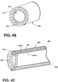
FIG. 4A is a sectional view illustrating anapparatus 400 of an optical imaging system with anoptical sight tube 402 in accordance with various aspects described herein. Theapparatus 400 is similar to that illustrated inFIG. 3A ; therefore, like parts will be identified with like numerals increased by 100, with it being understood that the description of the like parts of the first apparatus applies to the second apparatus, unless otherwise noted. - The
optical sight tube 402 includes two concentric longitudinal walls; an innerlongitudinal wall 418A and an outerlongitudinal wall 418B in spaced relation to one another. The cavity between the innerlongitudinal wall 418A and the outerlongitudinal wall 418B defines alongitudinal cooling groove 416. Thelongitudinal cooling groove 416 directs the cooling medium 404 from theinlet nozzle 406 connected to an external source to a plurality ofholes 420 in thelongitudinal wall 418A adjacent thedistal lens 410. The cooling medium 404 flows from the plurality of holes toward thedistal lens 410. -
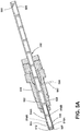
FIG. 5A is a sectional view illustrating another apparatus 500 of an optical imaging system with anoptical sight tube 502 in accordance with various aspects described herein. The apparatus 500 is similar to that illustrated inFIG. 4A ; therefore, like parts will be identified with like numerals increased by 100, with it being understood that the description of the like parts of the first apparatus applies to the second apparatus, unless otherwise noted. - The cooling medium 504 enters the
guide tube 514 nearest thedistal end 503 of theoptical sight tube 502. The cooling medium 504 flows through one ormore cooling grooves 522 within theguide tube 514. Theoptical sight tube 502 includes a plurality oflongitudinal cooling grooves 516A and B that overlie a portion of the coolinggrooves 522 within theguide tube 514. The cooling medium 504 flows from the coolinggrooves 522 through thelongitudinal cooling grooves 516A and B. The cooling medium 504 is purged through the plurality ofholes 520 at theend component 512 of thelongitudinal wall 518A. The plurality ofholes 520 adjacent to thedistal end 503 of theoptical sight tube 502 direct the cooling medium 504 from thelongitudinal grooves 516A and B towards thelens 510 at thedistal end 503 of theoptical sight tube 502 to purge thelens 510. - There can be any number of
holes 520 and longitudinal grooves 516 useful for purging air adjacent thedistal end 503 of theoptical sight tube 502 including, but not limited to, a configuration where there is a one-to-one relationship between the plurality ofholes 520 and the plurality of longitudinal grooves 516 or where there is a many-to-one relationship between the plurality ofholes 520 and the plurality of longitudinal grooves 516. - Additionally, the plurality of
holes lens distal end 403, 503 of theoptical sight tube lens lens 510 at thedistal end 503 of theoptical sight tube 504, directing cooling medium across thelens 510 at thedistal end 503 of theoptical sight tube 504 and combinations thereof. - Benefits of the above-described embodiments include an optical imaging system that does not include positioning a guide tube near the front end of the optics system. The resulting optical imaging system is constrained only by the diameter of the optical sight tube as opposed to the larger diameter guide tube. Hence, for cases where small diameter boreholes exist at the hot gas path, an optical image system implementing the above-described apparatus for insertion through an opening in an outer casing of a gas turbine engine can be used.
- This written description uses examples to disclose the invention, including the best mode, and also to enable any person skilled in the art to practice the invention, including making and using any devices or systems and performing any incorporated methods. The patentable scope of the invention is defined by the claims, and may include other examples that occur to those skilled in the art. Such other examples are intended to be within the scope of the claims if they have structural elements that do not differ from the literal language of the claims, or if they include equivalent structural elements with insubstantial differences from the literal languages of the claims.
- Various aspects and embodiments of the present invention are defined by the following numbered clauses:
- 1. An apparatus for insertion through an opening in an outer casing of a turbine engine and inspection of internal turbine components at elevated temperatures comprising:
- an optical sight tube configured to optically communicate with an interior of gas turbine engine via a distal end disposed at the interior and a proximal end disposed exterior of the internal turbine components and defined by a first longitudinal wall;
- at least one lens at the distal end of the optical sight tube adjacent to the longitudinal wall; and
- at least one longitudinal cooling groove in the longitudinal wall for flowing a cooling medium from a location external to the turbine to cool the optical sight tube at a location at least adjacent the distal end.
- 2. The apparatus of clause 1, further comprising a plurality of holes in the longitudinal wall adjacent the lens to direct cooling medium from the at least one groove toward the lens to purge the lens.
- 3. The apparatus of any preceding clause, comprising a plurality of longitudinal cooling grooves.
- 4. The apparatus of any preceding clause, comprising a plurality of grooves in the at least one lens.
- 5. The apparatus of any preceding clause, further comprising a second longitudinal wall concentric to the first longitudinal wall.
- 6. The apparatus of any preceding clause, wherein the at least one longitudinal cooling groove is a plurality of longitudinal cooling grooves embedded within the first and second longitudinal walls.
- 7. The apparatus of any preceding clause, further comprising a plurality of holes in the first longitudinal wall adjacent to the at least one lens at the distal end of the optical sight tube to direct the cooling medium from the at least one groove towards the at least one lens at the distal end of the optical sight tube to purge the at least one lens at the distal end of the optical sight tube wherein there is a one-to-one relationship between the plurality of holes in the longitudinal wall and the plurality of longitudinal grooves.
- 8. The apparatus of any preceding clause, further comprising a plurality of holes in the first longitudinal wall adjacent the at least one lens at the distal end of the optical sight tube to direct cooling medium from the at least one groove substantially perpendicular to the at least one lens at the distal end of the optical tube.
- 9. The apparatus of any preceding clause, further including an inlet nozzle removably secured to the optical sight tube to supply the cooling medium.
- 10. The apparatus of any preceding clause, further including a plurality of lenses located in spaced arrangement across the extent of the optical sight tube.
- 11. An optical sight tube for viewing internal components of a turbine engine, comprising:
- a first elongated wall;
- at least one lens at a distal end of the first elongated wall; and
- at least one longitudinal cooling groove in the first elongated wall for flowing a cooling medium from a location external to the turbine to cool the optical sight tube at a location at least adjacent the distal end.
- 12. The optical sight tube of any preceding clause, further comprising a plurality of holes in the first elongated wall adjacent the at least one lens to direct cooling medium from the at least one longitudinal cooling groove toward the at least one lens to purge the at least one lens.
- 13. The optical sight tube of any preceding clause, comprising a plurality of longitudinal cooling grooves.
- 14. The optical sight tube of any preceding clause, comprising a plurality of grooves in the at least one lens.
- 15. The optical sight tube of any preceding clause, further comprising a second elongated wall concentric to the first elongated wall.
- 16. The optical sight tube of any preceding clause, wherein the at least one longitudinal cooling groove is a plurality of longitudinal cooling grooves embedded within the first and second elongated walls.
- 17. The optical sight tube of any preceding clause, further comprising a plurality of holes in the first elongated wall adjacent to the at least one lens at the distal end of the optical sight tube to direct the cooling medium from the at least one groove towards the at least one lens at the distal end of the optical sight tube to purge the at least one lens at the distal end of the optical sight tube wherein there is a one-to-one relationship between the plurality of holes in the first elongated wall and the plurality of longitudinal grooves.
- 18. The optical sight tube of any preceding clause, further comprising a plurality of holes in the first elongated wall adjacent the at least one lens at the distal end of the optical sight tube to direct cooling medium from the at least one groove substantially perpendicular to the at least one lens at the distal end of the optical tube.
- 19. The optical sight tube of any preceding clause, further including a connection for removably securing an inlet nozzle to supply the cooling medium.
- 20. The optical sight tube of any preceding clause, further including a plurality of lenses located in spaced arrangement across the extent of the optical sight tube.
Claims (10)
- An apparatus (300) for insertion through an opening in an outer casing of a turbine engine and inspection of internal turbine components at elevated temperatures comprising:an optical sight tube (302) configured to optically communicate with an interior of gas turbine engine via a distal end (303) disposed at the interior and a proximal end (305) disposed exterior of the internal turbine components and defined by a first longitudinal wall (318);at least one lens (310) at the distal end (303) of the optical sight tube (302) adjacent to the longitudinal wall (318); andat least one longitudinal cooling groove (316) in the longitudinal wall (318) for flowing a cooling medium (304) from a location external to the turbine to cool the optical sight tube (302) at a location at least adjacent the distal end (303).
- The apparatus of claim 1, further comprising a plurality of holes (420) in the longitudinal wall (418) adjacent the lens (410) to direct cooling medium (404) from the at least one groove (416) toward the lens (410) to purge the lens (410).
- The apparatus of either of claim 1 or 2, comprising a plurality of longitudinal cooling grooves (516A, 516B).
- The apparatus of any preceding claim, comprising a plurality of grooves (316) in the at least one lens (310).
- The apparatus of any preceding claim, further comprising a second longitudinal wall (418B, 518B) concentric to the first longitudinal wall (418A, 518A).
- The apparatus of claim 5, wherein the at least one longitudinal cooling groove is a plurality of longitudinal cooling grooves (516A, 516B) embedded within the first (518A) and second (518B) longitudinal walls.
- The apparatus of claim 6, further comprising a plurality of holes (520) in the first longitudinal wall (518A) adjacent to the at least one lens (510) at the distal end of the optical sight tube (502) to direct the cooling medium (504) from the at least one groove towards the at least one lens (510) at the distal end (503) of the optical sight tube (502) to purge the at least one lens (510) at the distal end (503) of the optical sight tube (502) wherein there is a one-to-one relationship between the plurality of holes (520) in the longitudinal wall and the plurality of longitudinal grooves (516A, 516B).
- The apparatus of any preceding claim, further comprising a plurality of holes (520) in the first longitudinal wall (518A) adjacent the at least one lens (510) at the distal end (503) of the optical sight tube (502) to direct cooling medium (504) from the at least one groove substantially perpendicular to the at least one lens (510) at the distal end (503) of the optical tube.
- The apparatus of any preceding claim, further including an inlet nozzle (306) removably secured to the optical sight tube (302) to supply the cooling medium (304).
- The apparatus of any preceding claim, further including a plurality of lenses (308) located in spaced arrangement across the extent of the optical sight tube (302).
Applications Claiming Priority (1)
| Application Number | Priority Date | Filing Date | Title |
|---|---|---|---|
| US15/043,508 US10473528B2 (en) | 2016-02-13 | 2016-02-13 | Optical apparatus and sight tube for inspecting turbine engine components |
Publications (1)
| Publication Number | Publication Date |
|---|---|
| EP3206021A1 true EP3206021A1 (en) | 2017-08-16 |
Family
ID=57995121
Family Applications (1)
| Application Number | Title | Priority Date | Filing Date |
|---|---|---|---|
| EP17155204.5A Withdrawn EP3206021A1 (en) | 2016-02-13 | 2017-02-08 | Optical apparatus and sight tube for inspecting turbine engine components |
Country Status (5)
| Country | Link |
|---|---|
| US (1) | US10473528B2 (en) |
| EP (1) | EP3206021A1 (en) |
| JP (1) | JP2017142244A (en) |
| CN (1) | CN107085294B (en) |
| CA (1) | CA2956913A1 (en) |
Cited By (2)
| Publication number | Priority date | Publication date | Assignee | Title |
|---|---|---|---|---|
| EP3561495A1 (en) * | 2018-04-26 | 2019-10-30 | Rolls-Royce plc | Inspection and maintenance apparatus |
| EP3680651A3 (en) * | 2019-01-10 | 2020-08-12 | General Electric Company | Thermographic system and method for detecting water in a fan case |
Families Citing this family (12)
| Publication number | Priority date | Publication date | Assignee | Title |
|---|---|---|---|---|
| US10533901B2 (en) * | 2017-06-06 | 2020-01-14 | General Electric Company | Imaging system for inspecting components of turbomachines and method of assembly thereof |
| CN109458232B (en) * | 2018-10-16 | 2021-02-12 | 中广核核电运营有限公司 | Method for measuring cylinder partition plate hollow pit and concentricity of leaf top steam-resistant sheet thereof |
| US11103964B2 (en) * | 2018-12-06 | 2021-08-31 | General Electric Company | Service apparatus for use with rotary machines |
| CN110116820B (en) * | 2019-04-12 | 2022-08-02 | 西北工业大学 | 3D printing-based ground test method for nickel-based single crystal integral blade |
| US11536946B2 (en) * | 2020-03-17 | 2022-12-27 | Baker Hughes Holdings Llc | High temperature cooling tube for borescope |
| GB2606728A (en) * | 2021-05-18 | 2022-11-23 | Rolls Royce Plc | A mechanism |
| GB2606727B (en) | 2021-05-18 | 2023-11-08 | Rolls Royce Plc | Actuator |
| CN113359290A (en) * | 2021-06-02 | 2021-09-07 | 中国石油天然气股份有限公司 | Protective device of endoscope |
| US11946811B2 (en) * | 2021-08-13 | 2024-04-02 | Pratt & Whitney Canada Corp. | Non-contact high temperature measurement system |
| US11643943B1 (en) * | 2021-11-30 | 2023-05-09 | General Electric Company | Gimbal systems, apparatus, articles of manufacture and associated methods |
| US11971329B2 (en) | 2021-11-30 | 2024-04-30 | General Electric Company | Methods and apparatus to autonomously detect thermal anomalies |
| CN115201223B (en) * | 2022-06-07 | 2023-07-18 | 武汉盛永智杰科技有限公司 | Pipeline detection system |
Citations (7)
| Publication number | Priority date | Publication date | Assignee | Title |
|---|---|---|---|---|
| US20050281520A1 (en) * | 2004-06-16 | 2005-12-22 | Kehoskie Michael P | Borescope comprising fluid supply system |
| US20070107504A1 (en) * | 2005-01-18 | 2007-05-17 | Siemens Westinghouse Power Corporation | Inspection system for a turbine blade region of a turbine engine |
| US20080242927A1 (en) * | 2007-03-19 | 2008-10-02 | Yasuo Hirata | Cooling apparatus for endoscope and endoscope system |
| US20090259103A1 (en) * | 2008-04-11 | 2009-10-15 | Yasuo Hirata | Endoscope cooling device and endoscope system |
| US20110229307A1 (en) * | 2010-03-19 | 2011-09-22 | Lemieux Dennis H | Optical Monitoring System for a Turbine Engine |
| US20120171015A1 (en) * | 2011-01-04 | 2012-07-05 | General Electric Company | System for providing cooling and purging air flow to a rotary machine online monitoring system |
| EP2888577A1 (en) * | 2012-08-23 | 2015-07-01 | Siemens Energy, Inc. | System and method for visual inspection and 3d white light scanning of off-line industrial gas turbines and other power generation machinery |
Family Cites Families (18)
| Publication number | Priority date | Publication date | Assignee | Title |
|---|---|---|---|---|
| US865140A (en) * | 1904-12-30 | 1907-09-03 | Ira A Weaver | Wheeled plow. |
| GB191500140A (en) * | 1915-01-04 | 1915-07-15 | Spencer Graves | Coating for Wood, Metal or other Surfaces. |
| GB865140A (en) * | 1958-06-16 | 1961-04-12 | Canadian Patents Dev | Optical inspection device |
| DE3017144C2 (en) | 1980-05-05 | 1984-09-27 | Preussag Ag Feuerschutz, 2060 Bad Oldesloe | Device for reporting optical fire phenomena, in particular sparks |
| US4815276A (en) | 1987-09-10 | 1989-03-28 | The United States Of America As Represented By The Secretary Of The Air Force | Borescope plug |
| US5146244A (en) * | 1990-01-23 | 1992-09-08 | Rosemount Inc. | Window purging system for a combustion instrument |
| US5120252A (en) | 1990-04-05 | 1992-06-09 | General Electric Company | Method of mounting disk sensing optics onto circuit board of watthour meter |
| US7121098B2 (en) | 2003-04-30 | 2006-10-17 | Siemens Power Generation, Inc. | High-temperature inspection device and cooling apparatus therefor |
| US7662091B2 (en) | 2004-12-30 | 2010-02-16 | General Electric Company | Flexible borescope assembly for inspecting internal turbine components at elevated temperatures |
| US8674257B2 (en) * | 2008-02-11 | 2014-03-18 | Applied Materials, Inc. | Automatic focus and emissivity measurements for a substrate system |
| JP5185707B2 (en) * | 2008-06-25 | 2013-04-17 | オリンパス株式会社 | Endoscope guide tube and endoscope system |
| US8184151B2 (en) | 2009-09-18 | 2012-05-22 | Siemens Energy, Inc. | Flexible imaging fiber bundle monitoring system for combustion turbines |
| US10704958B2 (en) | 2010-10-21 | 2020-07-07 | Siemens Energy, Inc. | Method for monitoring a high-temperature region of interest in a turbine engine |
| US8899049B2 (en) * | 2011-01-07 | 2014-12-02 | General Electric Company | System and method for controlling combustor operating conditions based on flame detection |
| WO2013116080A1 (en) * | 2012-01-31 | 2013-08-08 | Siemens Energy, Inc. | System and method for automated optical inspection of industrial gas turbines and other power generation machinery with articulated multi-axis inspection scope |
| US8713999B2 (en) * | 2012-01-31 | 2014-05-06 | Siemens Energy, Inc. | System and method for automated optical inspection of industrial gas turbines and other power generation machinery with multi-axis inspection scope |
| US20130340443A1 (en) * | 2012-06-22 | 2013-12-26 | Rubens Salles | Plug Assembly for Borescope Port Cooling |
| JP5973297B2 (en) * | 2012-09-12 | 2016-08-23 | 本田技研工業株式会社 | Borescope |
-
2016
- 2016-02-13 US US15/043,508 patent/US10473528B2/en active Active
-
2017
- 2017-02-02 CA CA2956913A patent/CA2956913A1/en not_active Abandoned
- 2017-02-03 JP JP2017018089A patent/JP2017142244A/en active Pending
- 2017-02-08 EP EP17155204.5A patent/EP3206021A1/en not_active Withdrawn
- 2017-02-13 CN CN201710076037.6A patent/CN107085294B/en active Active
Patent Citations (7)
| Publication number | Priority date | Publication date | Assignee | Title |
|---|---|---|---|---|
| US20050281520A1 (en) * | 2004-06-16 | 2005-12-22 | Kehoskie Michael P | Borescope comprising fluid supply system |
| US20070107504A1 (en) * | 2005-01-18 | 2007-05-17 | Siemens Westinghouse Power Corporation | Inspection system for a turbine blade region of a turbine engine |
| US20080242927A1 (en) * | 2007-03-19 | 2008-10-02 | Yasuo Hirata | Cooling apparatus for endoscope and endoscope system |
| US20090259103A1 (en) * | 2008-04-11 | 2009-10-15 | Yasuo Hirata | Endoscope cooling device and endoscope system |
| US20110229307A1 (en) * | 2010-03-19 | 2011-09-22 | Lemieux Dennis H | Optical Monitoring System for a Turbine Engine |
| US20120171015A1 (en) * | 2011-01-04 | 2012-07-05 | General Electric Company | System for providing cooling and purging air flow to a rotary machine online monitoring system |
| EP2888577A1 (en) * | 2012-08-23 | 2015-07-01 | Siemens Energy, Inc. | System and method for visual inspection and 3d white light scanning of off-line industrial gas turbines and other power generation machinery |
Cited By (4)
| Publication number | Priority date | Publication date | Assignee | Title |
|---|---|---|---|---|
| EP3561495A1 (en) * | 2018-04-26 | 2019-10-30 | Rolls-Royce plc | Inspection and maintenance apparatus |
| US20190330997A1 (en) * | 2018-04-26 | 2019-10-31 | Rolls-Royce Plc | Inspection and maintenance apparatus |
| EP3680651A3 (en) * | 2019-01-10 | 2020-08-12 | General Electric Company | Thermographic system and method for detecting water in a fan case |
| US11474058B2 (en) | 2019-01-10 | 2022-10-18 | General Electric Company | Systems and methods for detecting water in a fan case |
Also Published As
| Publication number | Publication date |
|---|---|
| JP2017142244A (en) | 2017-08-17 |
| US20170234734A1 (en) | 2017-08-17 |
| CN107085294B (en) | 2020-04-24 |
| US10473528B2 (en) | 2019-11-12 |
| CN107085294A (en) | 2017-08-22 |
| CA2956913A1 (en) | 2017-08-13 |
Similar Documents
| Publication | Publication Date | Title |
|---|---|---|
| US10473528B2 (en) | Optical apparatus and sight tube for inspecting turbine engine components | |
| CN107203036B (en) | Optical imaging system for gas turbine engine | |
| US20170234772A1 (en) | Optical imaging system for inspecting turbine engine components and method for operating same | |
| US10775315B2 (en) | Probe insertion system | |
| US9458735B1 (en) | System and method for performing a visual inspection of a gas turbine engine | |
| EP3179237B1 (en) | System and method for locating a probe within a gas turbine engine | |
| CN106988798B (en) | System and method for performing in situ repair of internal components of a gas turbine engine | |
| US11225869B2 (en) | In situ gas turbine prevention of crack growth progression | |
| US9347855B2 (en) | Inspection arrangement | |
| CN107030384B (en) | Method of in situ material accumulation on tip of blade of gas turbine engine | |
| CN109312625A (en) | Turbine assembly maintaining method | |
| CN110925025B (en) | In-situ gas turbine prevention of crack growth development | |
| CN104081249B (en) | The system and method for turbine on-line checking including non-spherical lens | |
| EP2746752A2 (en) | Imaging system for inspecting a turbine | |
| EP3203017A1 (en) | Method of remotely stopping a crack in a component of a gas turbine engine | |
| EP3203018B1 (en) | Method of remotely stopping a crack in a component of a gas turbine engine | |
| CA2957264A1 (en) | In situ gas turbine prevention of crack growth progression |
Legal Events
| Date | Code | Title | Description |
|---|---|---|---|
| PUAI | Public reference made under article 153(3) epc to a published international application that has entered the european phase |
Free format text: ORIGINAL CODE: 0009012 |
|
| AK | Designated contracting states |
Kind code of ref document: A1 Designated state(s): AL AT BE BG CH CY CZ DE DK EE ES FI FR GB GR HR HU IE IS IT LI LT LU LV MC MK MT NL NO PL PT RO RS SE SI SK SM TR |
|
| AX | Request for extension of the european patent |
Extension state: BA ME |
|
| STAA | Information on the status of an ep patent application or granted ep patent |
Free format text: STATUS: THE APPLICATION IS DEEMED TO BE WITHDRAWN |
|
| 18D | Application deemed to be withdrawn |
Effective date: 20180217 |