EP3205864A1 - Engine controller and engine control method - Google Patents
Engine controller and engine control method Download PDFInfo
- Publication number
- EP3205864A1 EP3205864A1 EP17153204.7A EP17153204A EP3205864A1 EP 3205864 A1 EP3205864 A1 EP 3205864A1 EP 17153204 A EP17153204 A EP 17153204A EP 3205864 A1 EP3205864 A1 EP 3205864A1
- Authority
- EP
- European Patent Office
- Prior art keywords
- control term
- deviation
- combustion mode
- integral
- proportional
- Prior art date
- Legal status (The legal status is an assumption and is not a legal conclusion. Google has not performed a legal analysis and makes no representation as to the accuracy of the status listed.)
- Granted
Links
Images


Classifications
-
- F—MECHANICAL ENGINEERING; LIGHTING; HEATING; WEAPONS; BLASTING
- F02—COMBUSTION ENGINES; HOT-GAS OR COMBUSTION-PRODUCT ENGINE PLANTS
- F02D—CONTROLLING COMBUSTION ENGINES
- F02D41/00—Electrical control of supply of combustible mixture or its constituents
- F02D41/0002—Controlling intake air
- F02D41/0007—Controlling intake air for control of turbo-charged or super-charged engines
-
- F—MECHANICAL ENGINEERING; LIGHTING; HEATING; WEAPONS; BLASTING
- F02—COMBUSTION ENGINES; HOT-GAS OR COMBUSTION-PRODUCT ENGINE PLANTS
- F02B—INTERNAL-COMBUSTION PISTON ENGINES; COMBUSTION ENGINES IN GENERAL
- F02B37/00—Engines characterised by provision of pumps driven at least for part of the time by exhaust
- F02B37/12—Control of the pumps
- F02B37/24—Control of the pumps by using pumps or turbines with adjustable guide vanes
-
- F—MECHANICAL ENGINEERING; LIGHTING; HEATING; WEAPONS; BLASTING
- F02—COMBUSTION ENGINES; HOT-GAS OR COMBUSTION-PRODUCT ENGINE PLANTS
- F02D—CONTROLLING COMBUSTION ENGINES
- F02D41/00—Electrical control of supply of combustible mixture or its constituents
- F02D41/02—Circuit arrangements for generating control signals
- F02D41/021—Introducing corrections for particular conditions exterior to the engine
- F02D41/0235—Introducing corrections for particular conditions exterior to the engine in relation with the state of the exhaust gas treating apparatus
- F02D41/027—Introducing corrections for particular conditions exterior to the engine in relation with the state of the exhaust gas treating apparatus to purge or regenerate the exhaust gas treating apparatus
- F02D41/0275—Introducing corrections for particular conditions exterior to the engine in relation with the state of the exhaust gas treating apparatus to purge or regenerate the exhaust gas treating apparatus the exhaust gas treating apparatus being a NOx trap or adsorbent
-
- F—MECHANICAL ENGINEERING; LIGHTING; HEATING; WEAPONS; BLASTING
- F02—COMBUSTION ENGINES; HOT-GAS OR COMBUSTION-PRODUCT ENGINE PLANTS
- F02D—CONTROLLING COMBUSTION ENGINES
- F02D41/00—Electrical control of supply of combustible mixture or its constituents
- F02D41/02—Circuit arrangements for generating control signals
- F02D41/14—Introducing closed-loop corrections
- F02D41/1401—Introducing closed-loop corrections characterised by the control or regulation method
- F02D2041/1409—Introducing closed-loop corrections characterised by the control or regulation method using at least a proportional, integral or derivative controller
-
- F—MECHANICAL ENGINEERING; LIGHTING; HEATING; WEAPONS; BLASTING
- F02—COMBUSTION ENGINES; HOT-GAS OR COMBUSTION-PRODUCT ENGINE PLANTS
- F02D—CONTROLLING COMBUSTION ENGINES
- F02D41/00—Electrical control of supply of combustible mixture or its constituents
- F02D41/02—Circuit arrangements for generating control signals
- F02D41/14—Introducing closed-loop corrections
- F02D41/1401—Introducing closed-loop corrections characterised by the control or regulation method
- F02D2041/1413—Controller structures or design
- F02D2041/1422—Variable gain or coefficients
-
- Y—GENERAL TAGGING OF NEW TECHNOLOGICAL DEVELOPMENTS; GENERAL TAGGING OF CROSS-SECTIONAL TECHNOLOGIES SPANNING OVER SEVERAL SECTIONS OF THE IPC; TECHNICAL SUBJECTS COVERED BY FORMER USPC CROSS-REFERENCE ART COLLECTIONS [XRACs] AND DIGESTS
- Y02—TECHNOLOGIES OR APPLICATIONS FOR MITIGATION OR ADAPTATION AGAINST CLIMATE CHANGE
- Y02T—CLIMATE CHANGE MITIGATION TECHNOLOGIES RELATED TO TRANSPORTATION
- Y02T10/00—Road transport of goods or passengers
- Y02T10/10—Internal combustion engine [ICE] based vehicles
- Y02T10/12—Improving ICE efficiencies
Definitions
- the present invention relates to an engine controller and an engine control method for controlling a diesel engine or the like with a supercharger that is mounted in a vehicle or the like.
- An NOx occlusion-reduction catalyst for purifying exhaust gas is provided in an exhaust route of an engine (see Patent Document 1).
- the NOx occlusion-reduction catalyst occludes NOx (nitrogen oxides) in the exhaust gas in a lean combustion mode and reduces and removes NOx in a rich combustion mode.
- the engine is provided with a supercharger to improve thermal efficiency and output.
- the supercharger drives a turbine by using the exhaust gas flowing through the exhaust route, so as to supercharge air flowing through an intake route to the engine by a compressor that is coupled to the turbine.
- the exhaust route of the engine is provided with, as an adjustment mechanism for adjusting supercharging pressure, a waste gate valve by which the exhaust gas flowing into the turbine is bypassed, a variable nozzle turbo vane (a VNT vane) that changes an exhaust gas pass-through area of the turbine, and the like.
- Patent Document 1 JP-A-2010-24957
- a conventional supercharging pressure control system feeds back the supercharging pressure and operates the waste gate valve, the VNT vane, and the like, which are described above, to control opening degrees thereof, so as to eliminate a deviation between actual supercharging pressure, which has been subjected to the feedback, and target supercharging pressure. In this way, the supercharging pressure is controlled.
- excess closing of the waste gate valve and/or the VNT vane or the like possibly leads to significant overshooting of pressure (exhaust pressure) in the exhaust route when an operation of the NOx occlusion-reduction catalyst is shifted from that in the rich combustion mode to that in the lean combustion mode.
- Such overshooting of the exhaust pressure is desirably reduced from perspectives of hardware protection and fuel consumption. Accordingly, it can be raised, as measures for reducing the above-described overshooting, to change setting of a target value of the supercharging pressure by reduction and to increase minimum values of a valve opening degree of the waste gate valve and a vane opening degree of the VNT vane, and the like, for example.
- the measures as described above degrade drivability and exhaust performance, such as degraded responsiveness in accordance with an accelerator pedal operation (an acceleration instruction) and degraded fuel consumption.
- the invention has been made in view of the above-described problem and therefore has a purpose of providing an engine controller and an engine control method capable of controlling supercharging pressure while suppressing such a situation where exhaust pressure is overshot due to an operation of an NOx occlusion-reduction catalyst.
- the invention has following means.
- the invention is an engine controller that operates an exhaust flow rate adjustment mechanism to control supercharging pressure of an engine with a supercharger, the exhaust flow rate adjustment mechanism adjusting an exhaust gas flow rate through an exhaust route, and the supercharger driving a turbine by exhaust gas that flows through the exhaust route of the engine and supercharging air that flows through an intake route to the engine by a compressor coupled to the turbine.
- the engine controller includes: a deviation computation section that computes a deviation between an output value and a target value of the supercharging pressure; a proportional control term computation section that computes a proportional control term by multiplying the deviation by a proportional gain, the proportional control term being used to change an operation amount of the exhaust flow rate adjustment mechanism in proportion to the deviation; an integral control term computation section that computes an integral control term by multiplying time integration of the deviation by an integral gain, the integral control term being used to change the operation amount of the exhaust flow rate adjustment mechanism in proportion to the time integration of the deviation; and an operation amount computation section that adds the proportional control term and the integral control term to compute the operation amount of the exhaust flow rate adjustment mechanism.
- the exhaust route is provided with a NOx occlusion-reduction catalyst that occludes NOx in a lean combustion mode and reduces NOx in a rich combustion mode.
- the integral control term computation section initializes the time integration of the deviation to a specified value and computes the integral control term by multiplying the initialized time integration of the deviation by the integral gain at a time point at which a combustion mode of the NOx occlusion-reduction catalyst starts being shifted from the rich combustion mode to the lean combustion mode.
- the integral control term computation section initializes the time integration of the deviation to the specified value at the time point at which the NOx occlusion-reduction catalyst starts being shifted from the rich combustion mode to the lean combustion mode.
- a change in (overshooting of) exhaust pressure which possibly occurs at a time when the combustion mode is changed, can be alleviated or eliminated.
- a supercharging pressure control system to which the invention is applied, can appropriately control the supercharging pressure while suppressing such a situation where the exhaust pressure is overshot due to an operation of the NOx occlusion-reduction catalyst.
- the integral control term computation section preferably initializes the time integration of the deviation to the specified value and computes the integral control term by multiplying the specified value by the integral gain in the case where a pressure value of the exhaust gas exceeds a specified threshold value at the time point at which the combustion mode of the NOx occlusion-reduction catalyst starts being shifted from the rich combustion mode to the lean combustion mode.
- the proportional control term computation section preferably computes the proportional control term by multiplying the deviation by a specified first proportional gain when the NOx occlusion-reduction catalyst is in the rich combustion mode; preferably computes the proportional control term by multiplying the deviation by a second proportional gain that is larger than the first proportional gain until shifting of the NOx occlusion-reduction catalyst from the rich combustion mode to the lean combustion mode is completed; and preferably computes the proportional control term by multiplying the deviation by a third proportional gain that is larger than the second proportional gain when the NOx occlusion-reduction catalyst is in the lean combustion mode.
- the integral control term computation section preferably computes the integral control term by multiplying the time integration of the deviation by a specified first integral gain when the NOx occlusion-reduction catalyst is in the rich combustion mode; preferably computes the integral control term by multiplying the time integration of the deviation by a second integral gain that is larger than the first integral gain until shifting of the NOx occlusion-reduction catalyst from the rich combustion mode to the lean combustion mode is completed; and preferably computes the integral control term by multiplying the time integration of the deviation by a third integral gain that is larger than the second integral gain when the NOx occlusion-reduction catalyst is in the lean combustion mode.
- the invention as described so far is not limited to the above-described engine controller but can also be treated as an engine control method executed by the controller.
- the invention can provide the engine controller and the engine control method capable of shifting the operation of the NOx occlusion-reduction catalyst from the rich combustion mode to the lean combustion mode while suppressing the overshooting of the exhaust pressure in the engine with the supercharger.
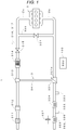
- This embodiment relates to a controller for a diesel engine with a supercharger that is mounted in a vehicle or the like. More specifically, the controller is embedded in an engine control system 1 as depicted in Fig. 1 , for example. A description will hereinafter be made on a configuration of the engine control system 1 and an operation thereof by focusing attention on supercharging pressure control for controlling supercharging pressure of air to be supercharged in an engine with reference to Fig. 1 .
- the engine control system 1 includes: a diesel engine 2; an intake pipe 2a and an exhaust pipe 2b, each of which is connected to the diesel engine 2; a supercharger 3; and an engine control unit 100 (hereinafter referred to as an ECU 100).
- the diesel engine 2 is an engine that uses diesel fuel as a power source. More specifically, the diesel engine 2 suctions ambient air (the air) from the intake pipe 2a that is an intake route connected to an ambient air inlet, combusts the diesel fuel to generate power, and discharges post-combustion exhaust gas to the exhaust pipe 2b that is an exhaust route.
- ambient air the air
- the diesel engine 2 suctions ambient air (the air) from the intake pipe 2a that is an intake route connected to an ambient air inlet, combusts the diesel fuel to generate power, and discharges post-combustion exhaust gas to the exhaust pipe 2b that is an exhaust route.
- an air filter 311, a mass flow sensor 312, a compressor 313, an intercooler 314, a throttle valve 315, a supercharging pressure sensor 316, and an intake air temperature sensor 317 are provided.
- a turbine 321, a first exhaust temperature sensor 322, a first lambda sensor 323, an NOx occlusion-reduction catalyst 324, a second exhaust temperature sensor 325, a second lambda sensor 326, a differential pressure sensor 327, and a diesel particulate filter 328 are provided.
- the engine control system 1 is provided with an exhaust gas recirculation (EGR) route 330 to reduce NOx and the like in the exhaust gas.
- EGR route 330 is a route through which the exhaust gas is circulated from an exhaust port of the diesel engine 2 to an intake port of the diesel engine 2, and is provided with an EGR valve 331 for adjusting a circulation amount of the exhaust gas.
- the air filter 311 removes dirt, dust, and the like from the air that is suctioned from the ambient air inlet so as to prevent foreign substances from being suctioned into the diesel engine 2.
- the mass flow sensor 312 is a sensor for detecting an air amount flowing between the air filter 311 and the compressor 313 and informs the ECU 100 of a detected value of the air amount.
- the compressor 313 and the turbine 321 are mechanically coupled via a bearing section 341 that supports the compressor 313 and the turbine 321 on the same rotary shaft. Due to such mechanical coupling, when the turbine 321 is rotationally driven by the exhaust gas that flows through the exhaust pipe 2b, the compressor 313 that is coupled to the turbine 321 is also rotationally driven. In this way, the air flowing through the intake pipe 2a is supercharged into the diesel engine 2. That is, the compressor 313, the turbine 321, and the bearing section 341 as a whole function as the supercharger 3 that supercharges the air into the diesel engine 2.
- the turbine 321 is provided with, as an exhaust flow rate adjustment mechanism that adjusts an exhaust flow rate, a variable nozzle turbo vane 321a (also referred to as a VNT vane) that changes an exhaust gas pass-through area of the turbine 321.
- a variable nozzle turbo vane 321a (also referred to as a VNT vane) that changes an exhaust gas pass-through area of the turbine 321.
- the variable nozzle turbo vane 321a adjusts the exhaust flow rate when a vane opening degree thereof that corresponds to an opening area of the vane is controlled by a control signal from the ECU 100.
- the exhaust flow rate is adjusted, just as described, and a workload of the turbine 321 is thereby changed.
- a workload of the compressor 313 is also changed, and the supercharging pressure can thereby be controlled.
- the exhaust flow rate adjustment mechanism is not limited to the above variable nozzle turbo vane 321a. Instead, a bypass route that bypasses the exhaust route running through the turbine 321 may be provided, and the bypass route may be provided with a waste gate valve for adjusting the exhaust flow rate. As described above, when the waste gate valve is used as the exhaust flow rate adjustment mechanism, a valve opening degree of the waste gate valve is controlled by the ECU 100. Furthermore, instead of selecting either one of the variable nozzle turbo vane 321a and the waste gate valve, a combination thereof may be used as the exhaust flow rate adjustment mechanism.
- the intercooler 314 cools the air that is compressed by the compressor 313 and delivers the cooled air to the throttle valve 315 side.
- a valve opening degree of the throttle valve 315 is controlled by the ECU 100, so as to adjust an intake air amount to the diesel engine 2.
- the supercharging pressure sensor 316 detects pressure (the supercharging pressure) of the air that is supercharged into the diesel engine 2 and informs the ECU 100 of the detected supercharging pressure (actual supercharging pressure).
- the intake air temperature sensor 317 detects a temperature of the air that is supercharged into the diesel engine 2 and informs the ECU 100 of the detected temperature.
- the first exhaust temperature sensor 322 and the first lambda sensor 323 are sensors that are provided in the exhaust route from the turbine 321 to the NOx occlusion-reduction catalyst 324. More specifically, the first exhaust temperature sensor 322 detects a temperature of the exhaust gas that is on an upstream side of the NOx occlusion-reduction catalyst 324, and informs the ECU 100 of the detected temperature. Meanwhile, the first lambda sensor 323 detects an air-fuel ratio of the exhaust gas that is on the upstream side of the NOx occlusion-reduction catalyst 324, and informs the ECU 100 of the detected air-fuel ratio.
- the second exhaust temperature sensor 325 and the second lambda sensor 326 are sensors that are provided in the exhaust route from the NOx occlusion-reduction catalyst 324 to the diesel particulate filter 328. More specifically, the second exhaust temperature sensor 325 detects a temperature of the exhaust gas that is on a downstream side of the NOx occlusion-reduction catalyst 324, and informs the ECU 100 of the detected temperature. Meanwhile, the second lambda sensor 326 detects an air-fuel ratio of the exhaust gas that is on the downstream side of the NOx occlusion-reduction catalyst 324, and informs the ECU 100 of the detected air-fuel ratio.
- the NOx occlusion-reduction catalyst 324 occludes NOx (nitrogen oxides) in the exhaust gas in a lean combustion mode and reduces and removes NOx in a rich combustion mode.
- NOx nitrogen oxides
- the air-fuel ratio of the exhaust gas is in a lean state.
- the rich combustion mode the air-fuel ratio of the exhaust gas is in a rich state.
- the differential pressure sensor 327 detects differential pressure between an upstream side and a downstream side of the diesel particulate filter 328 and informs the ECU 100 of the detected differential pressure.
- the diesel particulate filter 328 collects particulate substances contained in the exhaust gas and discharges the exhaust gas, from which an amount of the particulate substances is reduced, to the downstream side of the exhaust pipe 2b. Along with collection of the particulate substances, a filter function of the diesel particulate filter 328 is degraded, and the differential pressure, which is detected by the differential pressure sensor 327, is increased. However, the filter function can be restored by combusting the particulate substances.
- the ECU 100 is a microcomputer that includes input/output interfaces, an arithmetic processor for performing various types of arithmetic processes, a main memory for temporarily storing arithmetic processing data, and a storage for storing arithmetic programs, and realizes the following process when a control program for controlling the engine control system 1 is installed in the main memory. That is, the ECU 100 controls operations of the diesel engine 2 and the supercharger 3 by adjusting a fuel injection amount that is injected into the diesel engine 2 and the opening degrees of the various valve, vane, and the throttle on the basis of operation information by a driver, such as an accelerator pedal position, and detection information from the various sensors. That is, the controller for the diesel engine with the supercharger, to which the invention is applied, is realized as one function of the ECU 100.
- the ECU 100 causes the NOx occlusion-reduction catalyst 324 to occlude NOx in the lean combustion mode, changes the combustion mode to the rich combustion mode at specified timing on the basis of the detection information from the various sensors or the like at a time when an occluded NOx amount is increased, and controls the fuel injection amount and the opening degrees of the various valve, vane, and the throttle so as to reduce the air-fuel ratio to be lower than a theoretical air-fuel ratio.
- the ECU 100 adjusts the fuel injection amount and the opening degrees of the various valve, vane, and throttle to reduce the intake air amount. In this way, the temperature of the exhaust gas is increased to a specified temperature or higher by using thermal energy obtained through an operation of the diesel engine 2.
- the ECU 100 is not limited to the above-described microprocessor but may be dedicated hardware, such as a programmable logic device, that is designed to control the engine control system 1.
- a supercharging pressure control system 200 for controlling the supercharging pressure by a PI control system among functions realized by the above-described ECU 100 with reference to Fig. 2 .
- the ECU 100 includes a deviation computation section 110, a proportional control term computation section 120, an integral control term computation section 130, an operation amount computation section 140, a determination section 150, and a feedback gain decision section 160.
- the deviation computation section 110 computes a deviation between an output value and a target value of the supercharging pressure.
- the output value is the actual supercharging pressure that is detected by the above-described supercharging pressure sensor 316.
- the target value is target supercharging pressure that is set by the ECU 100 on the basis of information, such as accelerator pedal position information representing the acceleration instruction by the driver, the fuel injection amount of the diesel fuel injected into a cylinder of the diesel engine 2, and an engine speed.
- the proportional control term computation section 120 and the integral control term computation section 130 are informed of the deviation that is computed by the deviation computation section 110.
- the proportional control term computation section 120 computes a proportional control term that changes an operation amount of the variable nozzle turbo vane 321a in proportion to the deviation that is informed from the above-described deviation computation section 110. More specifically, the proportional control term computation section 120 computes the proportional control term by multiplying the deviation by a proportional gain Kp and informs the operation amount computation section 140 of the proportional control term.
- a value that is decided by the feedback gain decision section 160 is used as the proportional gain Kp.
- the integral control term computation section 130 computes an integral control term that changes the operation amount of the variable nozzle turbo vane 321a in proportion to time integration of the deviation that is informed from the above-described deviation computation section 110. More specifically, the integral control term computation section 130 integrates the deviation, which is changed in time, over a specified time, computes the integral control term by multiplying the time integration by an integral gain Ki, and informs the operation amount computation section 140 of the integral control term.
- the integral control term computation section 130 initializes the time integration to a specified value, such as 0, in accordance with a determination result by the determination section 150, which will be described below. As will be described below, a value that is decided by the feedback gain decision section 160 is used as the integral gain Ki.
- the operation amount computation section 140 computes the operation amount of the variable nozzle turbo vane 321a by adding the proportional control term, which is informed from the proportional control term computation section 120, and the integral control term, which is informed from the integral control term computation section 130.
- a drive signal that corresponds to the computed operation amount is output from the ECU 100 to the variable nozzle turbo vane 321a, the vane opening degree of the variable nozzle turbo vane 321a is changed in a manner to follow the operation amount that is computed by the operation amount computation section 140.
- the determination section 150 determines whether each of the combustion mode and the exhaust pressure satisfies a specified condition and instructs the integral control term computation section 130 to initialize the time integration of the deviation in accordance with the determination result.
- the determination section 150 executes a process depicted in the flowchart in Fig. 3 at every sampling time that is determined in advance.
- step S301 the determination section 150 determines whether the last combustion mode is the rich combustion mode. More specifically, if the combustion mode at the last sample time is the rich combustion mode, it is determined that the last combustion mode is the rich combustion mode. If the last combustion mode is the rich combustion mode (S301: Yes), the process proceeds to step S302. On the other hand, if the last combustion mode is not the rich combustion mode, that is, if the last combustion mode is the lean combustion mode or a combustion mode in which the air-fuel ratio is shifted from a rich state to a lean state (hereinafter referred to as a rich-to-lean transition mode), the process does not proceed to steps S302 to S304, and the process depicted in Fig. 3 is terminated.
- step S302 the determination section 150 determines whether the current combustion mode is the rich-to-lean transition mode. If the current combustion mode is the rich-to-lean transition mode in this step (S302: Yes), the process proceeds to step S303. If the current combustion mode is not the rich-to-lean transition mode, for example, if the current combustion mode remains to be the rich combustion mode like the last sample time (S302: No), the process does not proceed to step S303 or step S304, and the process depicted in Fig. 3 is terminated.
- step S303 the determination section 150 determines whether the exhaust pressure exceeds a specified threshold value. More specifically, the determination section 150 sets a pressure value that is lower than an upper limit pressure value by a specified margin as the threshold value in advance, the upper limit pressure value being allowed by the hardware in the engine control system 1. Then, it is determined in this step whether the exhaust pressure on the upstream side of the turbine 321, which is estimated from a physical model on the basis of detection results of the various sensors, exceeds the above threshold value, which is set in advance. If the exhaust pressure exceeds the threshold value (S303: Yes), the process proceeds to step S304. On the other hand, if the exhaust pressure does not exceed the threshold value (S303: No), the process does not proceed to step S304, and the process depicted in Fig. 3 is terminated.
- step S304 the determination section 150 instructs the integral control term computation section 130 to initialize the time integration to 0, and the process depicted in Fig. 3 is terminated.
- the time integration does not always have to be initialized to 0 but may be initialized to an arbitrary setting value in accordance with an operation state of the diesel engine 2.
- the determination section 150 executes the above process depicted in Fig. 3 . If both conditions of step S301 and step S302 are satisfied, in other words, only if the exhaust pressure exceeds the threshold value (S303: Yes) at a time point at which the NOx occlusion-reduction catalyst starts being shifted from the rich combustion mode to the lean combustion mode, the integral control term computation section 130 initializes the time integration of the deviation to the specified value. Just as described, the integral control term computation section 130 initializes the time integration of the deviation to the specified value. In this way, as it is apparent from a time response according to an example, which will be described below, a change in (overshooting of) the exhaust pressure, which possibly occurs at a time when the combustion mode is changed, can be alleviated or eliminated.
- step S302 if the condition of step S302 is satisfied (S302: Yes), the process may proceed to step S304 instead of proceeding to step S303, and the integral control term computation section 130 may initialize the time integration of the deviation to the specified value.
- step S303 is preferably performed. This is because unnecessary degradation of responsiveness of the supercharging pressure can be prevented by performing step S304 only when the exhaust pressure exceeds the threshold value. Degradation of a follow-up characteristic to the target supercharging pressure is prevented as described above. As a result, degradation of drivability and exhaust performance, such as degraded responsiveness in accordance with an accelerator pedal operation (the acceleration instruction) and degraded fuel consumption, can further be prevented.
- the feedback gain decision section 160 decides a specified feedback gain from plural feedback gains, which are set in advance, in accordance with the combustion mode of the NOx occlusion-reduction catalyst 324 and informs the proportional control term computation section 120 and the integral control term computation section 130 of the decided feedback gain.
- the proportional gain Kp For the proportional gain Kp, three types of proportional gains Kp1, Kp2, Kp3 are set in advance under a magnitude relationship as follows. That is, the feedback gain decision section 160 sets the proportional gain Kp in advance such that the magnitude relationship among the first proportional gain Kp1, the second proportional gain Kp2, and the third proportional gain Kp3 satisfies Kp1 ⁇ Kp2 ⁇ Kp3. As it is apparent from such a magnitude relationship, the first proportional gain Kp1 has the lowest sensitivity, the third proportional gain Kp3 has the highest sensitivity, and sensitivity of the second proportional gain Kp2 is located between Kp1 and Kp3.
- the integral gain Ki three types of integral gains Ki1, Ki2, Ki3 are set in advance under a magnitude relationship as follows. That is, the feedback gain decision section 160 sets the integral gain Ki in advance such that the magnitude relationship among the first integral gain Ki1, the second integral gain Ki2, and the third integral gain Ki3 satisfies Ki1 ⁇ Ki2 ⁇ Ki3. As it is apparent from such a magnitude relationship, the first integral gain Ki1 has the lowest sensitivity, the third integral gain Ki3 has the highest sensitivity, and sensitivity of the second integral gain Ki2 is located between Ki1 and Ki3.
- the feedback gain decision section 160 executes a process depicted in the flowchart in Fig. 4 at every sampling time that is determined in advance.
- step S401 the feedback gain decision section 160 determines whether the current combustion mode is the rich combustion mode. If the current combustion mode is the rich combustion mode (S401: Yes), the process proceeds to step S402. On the other hand, if the current combustion mode is not the rich combustion mode (S401: No), the process proceeds to step S403.
- step S402 the feedback gain decision section 160 decides the first proportional gain Kp1 with the low sensitivity as the proportional gain Kp and decides the first integral gain Ki1 with the low sensitivity as the integral gain Ki due to the following reason. Then, the process in Fig. 4 is terminated.
- the exhaust gas is high in enthalpy in the rich combustion mode. Thus, it is preferred to suppress the sensitivity of the supercharging pressure to the operation amount of the variable nozzle turbo vane 321a.
- the proportional control term computation section 120 and the integral control term computation section 130 are informed of the feedback gains that are decided in this step S402, and the following process is performed. More specifically, the proportional control term computation section 120 computes the proportional control term by multiplying the deviation, which is computed by the deviation computation section 110, by the first proportional gain Kp1. In addition, the integral control term computation section 130 computes the integral control term by multiplying the time integration of the deviation, which is computed by the deviation computation section 110, by the first integral gain Ki1.
- step S403 the feedback gain decision section 160 determines whether the current combustion mode is the rich-to-lean transition mode. If the current combustion mode is the rich-to-lean transition mode (S403: Yes), the process proceeds to step S404. On the other hand, if the current combustion mode is not the rich-to-lean transition mode (S403: No), that is, a lean transition mode, the process proceeds to step S405.
- step S404 the feedback gain decision section 160 decides the second proportional gain Kp2 with the middle sensitivity as the proportional gain Kp and decides the second integral gain Ki2 with the middle sensitivity as the integral gain Ki due to the following reason. Then, the process depicted in Fig. 4 is terminated.
- the exhaust gas is low in enthalpy in the rich-to-lean transition mode.
- the proportional control term computation section 120 and the integral control term computation section 130 are informed of the feedback gains that are decided in this step S404, and the following process is performed. More specifically, the proportional control term computation section 120 computes the proportional control term by multiplying the deviation, which is computed by the deviation computation section 110, by the second proportional gain Kp2. In addition, the integral control term computation section 130 computes the integral control term by multiplying the time integration of the deviation, which is computed by the deviation computation section 110, by the second integral gain Ki2.
- step S405 the feedback gain decision section 160 decides the third proportional gain Kp3 with the high sensitivity as the proportional gain Kp and decides the third integral gain Ki3 with the high sensitivity as the integral gain Ki due to the following reason. Then, the process depicted in Fig. 4 is terminated. Compared to the rich combustion mode, the exhaust gas is further low in enthalpy in the lean combustion mode. Thus, it is preferred to further increase the sensitivity of the supercharging pressure to the operation amount of the variable nozzle turbo vane 321a.
- the proportional control term computation section 120 and the integral control term computation section 130 are informed of the feedback gains that are decided in this step S405, and the following process is performed. More specifically, the proportional control term computation section 120 computes the proportional control term by multiplying the deviation, which is computed by the deviation computation section 110, by the third proportional gain Kp3. In addition, the integral control term computation section 130 computes the integral control term by multiplying the time integration of the deviation, which is computed by the deviation computation section 110, by the third integral gain Ki3.
- the feedback gain decision section 160 executes the process depicted in Fig. 4 and switches the feedback gains at three stages in accordance with state transition of the combustion mode. In this way, influences of the changes in the supercharging pressure, the exhaust pressure, and the like at the time when the combustion mode is changed can be alleviated or eliminated. That is, while overshooting of the exhaust pressure is suppressed, the operation of the NOx occlusion-reduction catalyst 324 can be shifted from the rich combustion mode to the lean combustion mode.
- Fig. 5 depicts one example of the above time responses.
- solid lines represent the various time responses of the supercharging pressure control system 200.
- broken lines represent the various time responses of a case where the supercharging pressure is controlled without considering the rich-to-lean transition mode.
- Fig. 6A is a graph in which a horizontal axis represents time and a vertical axis represents changes (a solid line, a broken line) in the proportional gain Kp as one example of a change in the feedback gain.
- the first proportional gain Kp1, the second proportional gain Kp2, and third proportional gain Kp3 are switched in this order in accordance with the order of the state transition of the rich combustion mode Rich, the rich-to-lean transition mode R2L, and the lean combustion mode Lean.
- the first proportional gain Kp1 is used in the rich combustion mode Rich to the rich-to-lean transition mode R2L and is switched to the third proportional gain Kp3 in accordance with the state transition to the lean combustion mode Lean.
- Fig. 6B is a graph in which a horizontal axis represents the time and a vertical axis represents operation amounts Command_to_VNT of the variable nozzle turbo vane 321a (a solid line, a broken line).
- Fig. 6B also depicts a time response of each of a proportional control term P-part and an integral control term I-part.
- the time integration is initialized at a time point at which the rich combustion mode Rich starts being shifted to the rich-to-lean transition mode R2L.
- the time response of the integral control term I-part is not influenced by the deviation under the rich combustion mode Rich and is promptly changed to a valve open side Open.
- the feedback gains are switched to the second proportional gain Kp2 and the second integral gain Ki2 for the rich-to-lean transition mode R2L.
- the time responses of the proportional control term P-part and the integral control term I-part are promptly changed to the valve open side Open.
- the time integration is not initialized even when the rich combustion mode Rich is shifted to the rich-to-lean transition mode R2L.
- the supercharging pressure is controlled by the same feedback gains (the first proportional gain Kp1, the first integral gain Ki1) as those in the rich combustion mode Rich.
- variable nozzle turbo vane 321a in the rich-to-lean transition mode R2L is more promptly changed to the valve open side Open in the embodiment than in the comparative example.
- the time responses of the exhaust pressure and the supercharging pressure differ.
- Fig. 6C is a graph in which a horizontal axis represents the time and a vertical axis represents the changes in the exhaust pressure (a solid line, a broken line).
- an upper limit value Limit_for_HW_protection of hardware protection and a threshold value Threshold that is used in step S303 are also depicted.
- the variable nozzle turbo vane 321a can smoothly be operated to the valve open side Open.
- a horizontal axis represents the time
- a vertical axis represents the target supercharging pressure (a one-dot chain line) and the actual supercharging pressure (a solid line, a broken line).
- the supercharging pressure follows the target supercharging pressure in the rich-to-lean transition mode R2L when compared to the comparative example (the broken line).
- the target supercharging pressure follows the target supercharging pressure in the rich-to-lean transition mode R2L when compared to the comparative example (the broken line).
- the time integration in integral control is initialized, and the feedback gains are switched in consideration of such a point that an internal state is drastically changed as in the rich-to-lean transition mode R2L. Accordingly, compared to the comparative example, the supercharging pressure can be controlled in the embodiment while overshooting of the exhaust pressure is suppressed. That is, in the embodiment, the supercharging pressure can appropriately be controlled while a situation where the exhaust pressure is overshot due to the operation of the NOx occlusion-reduction catalyst is suppressed.
- the supercharging pressure control system is not limited to a case where the above-described proportional control and integration control are executed.
- the supercharging pressure control system may be applied to a so-called PID control system in which the proportional control, the integral control, and differential control are combined. More specifically, in regard to P control (the proportional control) and I control (the integral control), the operation amount only needs to be computed in a similar manner to computation in the proportional control term computation section 120 and the integral control term computation section 130 described above.
- a differential gain Kd that corresponds to three types of the rich combustion mode, the rich-to-lean transition mode, and the lean combustion mode, for example, is set, and the differential gain Kd only needs to be switched stepwise in accordance with the transition of the combustion mode.
- the actual supercharging pressure is not limited to the value that is estimated from the value obtained by the above-described supercharging pressure sensor 316, but a value that is estimated from the value obtained by any of the various sensors provided in the engine control system 1 may be used.
- the exhaust pressure is not limited to a case where the value that is estimated from the value obtained by any of the various sensors provided in the engine control system 1 is used.
- a pressure sensor that detects the exhaust pressure may be provided between the diesel engine 2 and the variable nozzle turbo vane 321a, and a detected value of the pressure sensor may be used as the exhaust pressure.
- the invention may be realized by providing a non-temporary recording medium, in which an engine control program that realizes the functions of the above-described embodiment is recorded, in the ECU and causing a processing unit (a CPU, an MPU) of the ECU to read out and execute the engine control program that is recorded in the recording medium.
- a processing unit a CPU, an MPU
- the engine control program that is read out from the non-temporary recording medium realizes the functions of the above-described embodiment.
- the engine control program and the non-temporary recording medium, in which this program is recorded also serve as one aspect of the invention.
- non-temporary recording medium that provides the engine control program
- a flexible disc for example, a flexible disc, a hard disc, a magnet-optical disc, an optical disc such as CD-ROM, CD-R, CD-RW, DVD-ROM, DVD-RAM, DVD-RW, and DVD+RW, a magnetic tape, a non-volatile memory card, and a ROM are included.
- the program may be downloadable via a communication network.
Landscapes
- Engineering & Computer Science (AREA)
- Chemical & Material Sciences (AREA)
- Combustion & Propulsion (AREA)
- Mechanical Engineering (AREA)
- General Engineering & Computer Science (AREA)
- Exhaust Gas After Treatment (AREA)
- Electrical Control Of Air Or Fuel Supplied To Internal-Combustion Engine (AREA)
- Output Control And Ontrol Of Special Type Engine (AREA)
- Combined Controls Of Internal Combustion Engines (AREA)
- Supercharger (AREA)
Abstract
Description
- The present invention relates to an engine controller and an engine control method for controlling a diesel engine or the like with a supercharger that is mounted in a vehicle or the like.
- An NOx occlusion-reduction catalyst for purifying exhaust gas is provided in an exhaust route of an engine (see Patent Document 1). The NOx occlusion-reduction catalyst occludes NOx (nitrogen oxides) in the exhaust gas in a lean combustion mode and reduces and removes NOx in a rich combustion mode.
- It has been widely practiced that the engine is provided with a supercharger to improve thermal efficiency and output. The supercharger drives a turbine by using the exhaust gas flowing through the exhaust route, so as to supercharge air flowing through an intake route to the engine by a compressor that is coupled to the turbine. The exhaust route of the engine is provided with, as an adjustment mechanism for adjusting supercharging pressure, a waste gate valve by which the exhaust gas flowing into the turbine is bypassed, a variable nozzle turbo vane (a VNT vane) that changes an exhaust gas pass-through area of the turbine, and the like.
- Patent Document 1:
JP-A-2010-24957 - A conventional supercharging pressure control system feeds back the supercharging pressure and operates the waste gate valve, the VNT vane, and the like, which are described above, to control opening degrees thereof, so as to eliminate a deviation between actual supercharging pressure, which has been subjected to the feedback, and target supercharging pressure. In this way, the supercharging pressure is controlled. However, in the conventional supercharging pressure control system, excess closing of the waste gate valve and/or the VNT vane or the like possibly leads to significant overshooting of pressure (exhaust pressure) in the exhaust route when an operation of the NOx occlusion-reduction catalyst is shifted from that in the rich combustion mode to that in the lean combustion mode.
- Such overshooting of the exhaust pressure is desirably reduced from perspectives of hardware protection and fuel consumption. Accordingly, it can be raised, as measures for reducing the above-described overshooting, to change setting of a target value of the supercharging pressure by reduction and to increase minimum values of a valve opening degree of the waste gate valve and a vane opening degree of the VNT vane, and the like, for example. However, the measures as described above degrade drivability and exhaust performance, such as degraded responsiveness in accordance with an accelerator pedal operation (an acceleration instruction) and degraded fuel consumption.
- The invention has been made in view of the above-described problem and therefore has a purpose of providing an engine controller and an engine control method capable of controlling supercharging pressure while suppressing such a situation where exhaust pressure is overshot due to an operation of an NOx occlusion-reduction catalyst.
- In order to solve the above-described conventional problem, the invention has following means.
- The invention is an engine controller that operates an exhaust flow rate adjustment mechanism to control supercharging pressure of an engine with a supercharger, the exhaust flow rate adjustment mechanism adjusting an exhaust gas flow rate through an exhaust route, and the supercharger driving a turbine by exhaust gas that flows through the exhaust route of the engine and supercharging air that flows through an intake route to the engine by a compressor coupled to the turbine. The engine controller includes: a deviation computation section that computes a deviation between an output value and a target value of the supercharging pressure; a proportional control term computation section that computes a proportional control term by multiplying the deviation by a proportional gain, the proportional control term being used to change an operation amount of the exhaust flow rate adjustment mechanism in proportion to the deviation; an integral control term computation section that computes an integral control term by multiplying time integration of the deviation by an integral gain, the integral control term being used to change the operation amount of the exhaust flow rate adjustment mechanism in proportion to the time integration of the deviation; and an operation amount computation section that adds the proportional control term and the integral control term to compute the operation amount of the exhaust flow rate adjustment mechanism. The exhaust route is provided with a NOx occlusion-reduction catalyst that occludes NOx in a lean combustion mode and reduces NOx in a rich combustion mode. The integral control term computation section initializes the time integration of the deviation to a specified value and computes the integral control term by multiplying the initialized time integration of the deviation by the integral gain at a time point at which a combustion mode of the NOx occlusion-reduction catalyst starts being shifted from the rich combustion mode to the lean combustion mode.
- According to the invention, the integral control term computation section initializes the time integration of the deviation to the specified value at the time point at which the NOx occlusion-reduction catalyst starts being shifted from the rich combustion mode to the lean combustion mode. In this way, a change in (overshooting of) exhaust pressure, which possibly occurs at a time when the combustion mode is changed, can be alleviated or eliminated. That is, a supercharging pressure control system, to which the invention is applied, can appropriately control the supercharging pressure while suppressing such a situation where the exhaust pressure is overshot due to an operation of the NOx occlusion-reduction catalyst.
- In addition, in the invention, the integral control term computation section preferably initializes the time integration of the deviation to the specified value and computes the integral control term by multiplying the specified value by the integral gain in the case where a pressure value of the exhaust gas exceeds a specified threshold value at the time point at which the combustion mode of the NOx occlusion-reduction catalyst starts being shifted from the rich combustion mode to the lean combustion mode.
- Furthermore, in the invention, the proportional control term computation section: preferably computes the proportional control term by multiplying the deviation by a specified first proportional gain when the NOx occlusion-reduction catalyst is in the rich combustion mode; preferably computes the proportional control term by multiplying the deviation by a second proportional gain that is larger than the first proportional gain until shifting of the NOx occlusion-reduction catalyst from the rich combustion mode to the lean combustion mode is completed; and preferably computes the proportional control term by multiplying the deviation by a third proportional gain that is larger than the second proportional gain when the NOx occlusion-reduction catalyst is in the lean combustion mode.
- Moreover, in the invention, the integral control term computation section: preferably computes the integral control term by multiplying the time integration of the deviation by a specified first integral gain when the NOx occlusion-reduction catalyst is in the rich combustion mode; preferably computes the integral control term by multiplying the time integration of the deviation by a second integral gain that is larger than the first integral gain until shifting of the NOx occlusion-reduction catalyst from the rich combustion mode to the lean combustion mode is completed; and preferably computes the integral control term by multiplying the time integration of the deviation by a third integral gain that is larger than the second integral gain when the NOx occlusion-reduction catalyst is in the lean combustion mode.
- The invention as described so far is not limited to the above-described engine controller but can also be treated as an engine control method executed by the controller.
- The invention can provide the engine controller and the engine control method capable of shifting the operation of the NOx occlusion-reduction catalyst from the rich combustion mode to the lean combustion mode while suppressing the overshooting of the exhaust pressure in the engine with the supercharger.
-
-
Fig. 1 is a view of an overall configuration of an engine control system in which an engine controller, to which the invention is applied, is embedded; -
Fig. 2 is a diagram for explaining a specific configuration of a supercharging pressure control system that is realized by the engine controller, to which the invention is applied; -
Fig. 3 is a flowchart for explaining a process flow that is executed by a determination section of a supercharging pressure control system; -
Fig. 4 is a flowchart for explaining a process flow that is executed by a feedback gain decision section of the supercharging pressure control system; -
Fig. 5 is a graph that represents a specific example of state transition of a combustion mode; and -
Fig. 6 includes graphs that represent various time responses in an example according to the supercharging pressure control system. - A description will be made on a mode for carrying out the invention (hereinafter referred to as this embodiment) by using a specific example. This embodiment relates to a controller for a diesel engine with a supercharger that is mounted in a vehicle or the like. More specifically, the controller is embedded in an
engine control system 1 as depicted inFig. 1 , for example. A description will hereinafter be made on a configuration of theengine control system 1 and an operation thereof by focusing attention on supercharging pressure control for controlling supercharging pressure of air to be supercharged in an engine with reference toFig. 1 . - As depicted in
Fig. 1 , theengine control system 1 includes: adiesel engine 2; an intake pipe 2a and an exhaust pipe 2b, each of which is connected to thediesel engine 2; asupercharger 3; and an engine control unit 100 (hereinafter referred to as an ECU 100). - The
diesel engine 2 is an engine that uses diesel fuel as a power source. More specifically, thediesel engine 2 suctions ambient air (the air) from the intake pipe 2a that is an intake route connected to an ambient air inlet, combusts the diesel fuel to generate power, and discharges post-combustion exhaust gas to the exhaust pipe 2b that is an exhaust route. - From an upstream side to a downstream side (the
diesel engine 2 side) of the intake pipe 2a, anair filter 311, amass flow sensor 312, acompressor 313, anintercooler 314, a throttle valve 315, a supercharging pressure sensor 316, and an intake air temperature sensor 317 are provided. From an upstream side (thediesel engine 2 side) to a downstream side of the exhaust pipe 2b, aturbine 321, a first exhaust temperature sensor 322, a first lambda sensor 323, an NOx occlusion-reduction catalyst 324, a second exhaust temperature sensor 325, a second lambda sensor 326, adifferential pressure sensor 327, and adiesel particulate filter 328 are provided. - In addition, the
engine control system 1 is provided with an exhaust gas recirculation (EGR)route 330 to reduce NOx and the like in the exhaust gas. More specifically, the EGRroute 330 is a route through which the exhaust gas is circulated from an exhaust port of thediesel engine 2 to an intake port of thediesel engine 2, and is provided with an EGR valve 331 for adjusting a circulation amount of the exhaust gas. - The
air filter 311 removes dirt, dust, and the like from the air that is suctioned from the ambient air inlet so as to prevent foreign substances from being suctioned into thediesel engine 2. - The
mass flow sensor 312 is a sensor for detecting an air amount flowing between theair filter 311 and thecompressor 313 and informs theECU 100 of a detected value of the air amount. - The
compressor 313 and theturbine 321 are mechanically coupled via abearing section 341 that supports thecompressor 313 and theturbine 321 on the same rotary shaft. Due to such mechanical coupling, when theturbine 321 is rotationally driven by the exhaust gas that flows through the exhaust pipe 2b, thecompressor 313 that is coupled to theturbine 321 is also rotationally driven. In this way, the air flowing through the intake pipe 2a is supercharged into thediesel engine 2. That is, thecompressor 313, theturbine 321, and thebearing section 341 as a whole function as thesupercharger 3 that supercharges the air into thediesel engine 2. - Here, the
turbine 321 is provided with, as an exhaust flow rate adjustment mechanism that adjusts an exhaust flow rate, a variable nozzle turbo vane 321a (also referred to as a VNT vane) that changes an exhaust gas pass-through area of theturbine 321. As will be described below, the variable nozzle turbo vane 321a adjusts the exhaust flow rate when a vane opening degree thereof that corresponds to an opening area of the vane is controlled by a control signal from theECU 100. The exhaust flow rate is adjusted, just as described, and a workload of theturbine 321 is thereby changed. As a result, a workload of thecompressor 313 is also changed, and the supercharging pressure can thereby be controlled. - Note that the exhaust flow rate adjustment mechanism is not limited to the above variable nozzle turbo vane 321a. Instead, a bypass route that bypasses the exhaust route running through the
turbine 321 may be provided, and the bypass route may be provided with a waste gate valve for adjusting the exhaust flow rate. As described above, when the waste gate valve is used as the exhaust flow rate adjustment mechanism, a valve opening degree of the waste gate valve is controlled by theECU 100. Furthermore, instead of selecting either one of the variable nozzle turbo vane 321a and the waste gate valve, a combination thereof may be used as the exhaust flow rate adjustment mechanism. - The
intercooler 314 cools the air that is compressed by thecompressor 313 and delivers the cooled air to the throttle valve 315 side. - A valve opening degree of the throttle valve 315 is controlled by the
ECU 100, so as to adjust an intake air amount to thediesel engine 2. - The supercharging pressure sensor 316 detects pressure (the supercharging pressure) of the air that is supercharged into the
diesel engine 2 and informs theECU 100 of the detected supercharging pressure (actual supercharging pressure). - The intake air temperature sensor 317 detects a temperature of the air that is supercharged into the
diesel engine 2 and informs theECU 100 of the detected temperature. - The first exhaust temperature sensor 322 and the first lambda sensor 323 are sensors that are provided in the exhaust route from the
turbine 321 to the NOx occlusion-reduction catalyst 324. More specifically, the first exhaust temperature sensor 322 detects a temperature of the exhaust gas that is on an upstream side of the NOx occlusion-reduction catalyst 324, and informs theECU 100 of the detected temperature. Meanwhile, the first lambda sensor 323 detects an air-fuel ratio of the exhaust gas that is on the upstream side of the NOx occlusion-reduction catalyst 324, and informs theECU 100 of the detected air-fuel ratio. - The second exhaust temperature sensor 325 and the second lambda sensor 326 are sensors that are provided in the exhaust route from the NOx occlusion-
reduction catalyst 324 to thediesel particulate filter 328. More specifically, the second exhaust temperature sensor 325 detects a temperature of the exhaust gas that is on a downstream side of the NOx occlusion-reduction catalyst 324, and informs theECU 100 of the detected temperature. Meanwhile, the second lambda sensor 326 detects an air-fuel ratio of the exhaust gas that is on the downstream side of the NOx occlusion-reduction catalyst 324, and informs theECU 100 of the detected air-fuel ratio. - The NOx occlusion-
reduction catalyst 324 occludes NOx (nitrogen oxides) in the exhaust gas in a lean combustion mode and reduces and removes NOx in a rich combustion mode. In the lean combustion mode, the air-fuel ratio of the exhaust gas is in a lean state. In the rich combustion mode, the air-fuel ratio of the exhaust gas is in a rich state. - The
differential pressure sensor 327 detects differential pressure between an upstream side and a downstream side of thediesel particulate filter 328 and informs theECU 100 of the detected differential pressure. - The
diesel particulate filter 328 collects particulate substances contained in the exhaust gas and discharges the exhaust gas, from which an amount of the particulate substances is reduced, to the downstream side of the exhaust pipe 2b. Along with collection of the particulate substances, a filter function of thediesel particulate filter 328 is degraded, and the differential pressure, which is detected by thedifferential pressure sensor 327, is increased. However, the filter function can be restored by combusting the particulate substances. - The
ECU 100 is a microcomputer that includes input/output interfaces, an arithmetic processor for performing various types of arithmetic processes, a main memory for temporarily storing arithmetic processing data, and a storage for storing arithmetic programs, and realizes the following process when a control program for controlling theengine control system 1 is installed in the main memory. That is, theECU 100 controls operations of thediesel engine 2 and thesupercharger 3 by adjusting a fuel injection amount that is injected into thediesel engine 2 and the opening degrees of the various valve, vane, and the throttle on the basis of operation information by a driver, such as an accelerator pedal position, and detection information from the various sensors. That is, the controller for the diesel engine with the supercharger, to which the invention is applied, is realized as one function of theECU 100. - In addition, the
ECU 100 causes the NOx occlusion-reduction catalyst 324 to occlude NOx in the lean combustion mode, changes the combustion mode to the rich combustion mode at specified timing on the basis of the detection information from the various sensors or the like at a time when an occluded NOx amount is increased, and controls the fuel injection amount and the opening degrees of the various valve, vane, and the throttle so as to reduce the air-fuel ratio to be lower than a theoretical air-fuel ratio. Furthermore, when determining that regeneration of thediesel particulate filter 328 by combustion is necessary on the basis of the differential pressure between the upstream side and the downstream side thereof or the like, theECU 100 adjusts the fuel injection amount and the opening degrees of the various valve, vane, and throttle to reduce the intake air amount. In this way, the temperature of the exhaust gas is increased to a specified temperature or higher by using thermal energy obtained through an operation of thediesel engine 2. - Note that the
ECU 100 is not limited to the above-described microprocessor but may be dedicated hardware, such as a programmable logic device, that is designed to control theengine control system 1. - A description will hereinafter be made on a supercharging
pressure control system 200 for controlling the supercharging pressure by a PI control system among functions realized by the above-describedECU 100 with reference toFig. 2 . - As depicted in
Fig. 2 , as a function of realizing the superchargingpressure control system 200, theECU 100 includes a deviation computation section 110, a proportional controlterm computation section 120, an integral controlterm computation section 130, an operationamount computation section 140, adetermination section 150, and a feedbackgain decision section 160. - The deviation computation section 110 computes a deviation between an output value and a target value of the supercharging pressure. Here, the output value is the actual supercharging pressure that is detected by the above-described supercharging pressure sensor 316. In addition, the target value is target supercharging pressure that is set by the
ECU 100 on the basis of information, such as accelerator pedal position information representing the acceleration instruction by the driver, the fuel injection amount of the diesel fuel injected into a cylinder of thediesel engine 2, and an engine speed. The proportional controlterm computation section 120 and the integral controlterm computation section 130 are informed of the deviation that is computed by the deviation computation section 110. - The proportional control
term computation section 120 computes a proportional control term that changes an operation amount of the variable nozzle turbo vane 321a in proportion to the deviation that is informed from the above-described deviation computation section 110. More specifically, the proportional controlterm computation section 120 computes the proportional control term by multiplying the deviation by a proportional gain Kp and informs the operationamount computation section 140 of the proportional control term. Here, as will be described below, a value that is decided by the feedbackgain decision section 160 is used as the proportional gain Kp. - The integral control
term computation section 130 computes an integral control term that changes the operation amount of the variable nozzle turbo vane 321a in proportion to time integration of the deviation that is informed from the above-described deviation computation section 110. More specifically, the integral controlterm computation section 130 integrates the deviation, which is changed in time, over a specified time, computes the integral control term by multiplying the time integration by an integral gain Ki, and informs the operationamount computation section 140 of the integral control term. Here, the integral controlterm computation section 130 initializes the time integration to a specified value, such as 0, in accordance with a determination result by thedetermination section 150, which will be described below. As will be described below, a value that is decided by the feedbackgain decision section 160 is used as the integral gain Ki. - The operation
amount computation section 140 computes the operation amount of the variable nozzle turbo vane 321a by adding the proportional control term, which is informed from the proportional controlterm computation section 120, and the integral control term, which is informed from the integral controlterm computation section 130. When a drive signal that corresponds to the computed operation amount is output from theECU 100 to the variable nozzle turbo vane 321a, the vane opening degree of the variable nozzle turbo vane 321a is changed in a manner to follow the operation amount that is computed by the operationamount computation section 140. - The
determination section 150 determines whether each of the combustion mode and the exhaust pressure satisfies a specified condition and instructs the integral controlterm computation section 130 to initialize the time integration of the deviation in accordance with the determination result. - More specifically, the
determination section 150 executes a process depicted in the flowchart inFig. 3 at every sampling time that is determined in advance. - In step S301, the
determination section 150 determines whether the last combustion mode is the rich combustion mode. More specifically, if the combustion mode at the last sample time is the rich combustion mode, it is determined that the last combustion mode is the rich combustion mode. If the last combustion mode is the rich combustion mode (S301: Yes), the process proceeds to step S302. On the other hand, if the last combustion mode is not the rich combustion mode, that is, if the last combustion mode is the lean combustion mode or a combustion mode in which the air-fuel ratio is shifted from a rich state to a lean state (hereinafter referred to as a rich-to-lean transition mode), the process does not proceed to steps S302 to S304, and the process depicted inFig. 3 is terminated. - In step S302, the
determination section 150 determines whether the current combustion mode is the rich-to-lean transition mode. If the current combustion mode is the rich-to-lean transition mode in this step (S302: Yes), the process proceeds to step S303. If the current combustion mode is not the rich-to-lean transition mode, for example, if the current combustion mode remains to be the rich combustion mode like the last sample time (S302: No), the process does not proceed to step S303 or step S304, and the process depicted inFig. 3 is terminated. - In step S303, the
determination section 150 determines whether the exhaust pressure exceeds a specified threshold value. More specifically, thedetermination section 150 sets a pressure value that is lower than an upper limit pressure value by a specified margin as the threshold value in advance, the upper limit pressure value being allowed by the hardware in theengine control system 1. Then, it is determined in this step whether the exhaust pressure on the upstream side of theturbine 321, which is estimated from a physical model on the basis of detection results of the various sensors, exceeds the above threshold value, which is set in advance. If the exhaust pressure exceeds the threshold value (S303: Yes), the process proceeds to step S304. On the other hand, if the exhaust pressure does not exceed the threshold value (S303: No), the process does not proceed to step S304, and the process depicted inFig. 3 is terminated. - In step S304, the
determination section 150 instructs the integral controlterm computation section 130 to initialize the time integration to 0, and the process depicted inFig. 3 is terminated. Note that the time integration does not always have to be initialized to 0 but may be initialized to an arbitrary setting value in accordance with an operation state of thediesel engine 2. - The
determination section 150 executes the above process depicted inFig. 3 . If both conditions of step S301 and step S302 are satisfied, in other words, only if the exhaust pressure exceeds the threshold value (S303: Yes) at a time point at which the NOx occlusion-reduction catalyst starts being shifted from the rich combustion mode to the lean combustion mode, the integral controlterm computation section 130 initializes the time integration of the deviation to the specified value. Just as described, the integral controlterm computation section 130 initializes the time integration of the deviation to the specified value. In this way, as it is apparent from a time response according to an example, which will be described below, a change in (overshooting of) the exhaust pressure, which possibly occurs at a time when the combustion mode is changed, can be alleviated or eliminated. - Note that, if the condition of step S302 is satisfied (S302: Yes), the process may proceed to step S304 instead of proceeding to step S303, and the integral control
term computation section 130 may initialize the time integration of the deviation to the specified value. However, step S303 is preferably performed. This is because unnecessary degradation of responsiveness of the supercharging pressure can be prevented by performing step S304 only when the exhaust pressure exceeds the threshold value. Degradation of a follow-up characteristic to the target supercharging pressure is prevented as described above. As a result, degradation of drivability and exhaust performance, such as degraded responsiveness in accordance with an accelerator pedal operation (the acceleration instruction) and degraded fuel consumption, can further be prevented. - The feedback
gain decision section 160 decides a specified feedback gain from plural feedback gains, which are set in advance, in accordance with the combustion mode of the NOx occlusion-reduction catalyst 324 and informs the proportional controlterm computation section 120 and the integral controlterm computation section 130 of the decided feedback gain. - Prior to a description on a feedback gain decision process, a description will first be made on the feedback gain that is used in the decision process.
- For the proportional gain Kp, three types of proportional gains Kp1, Kp2, Kp3 are set in advance under a magnitude relationship as follows. That is, the feedback
gain decision section 160 sets the proportional gain Kp in advance such that the magnitude relationship among the first proportional gain Kp1, the second proportional gain Kp2, and the third proportional gain Kp3 satisfies Kp1 < Kp2 < Kp3. As it is apparent from such a magnitude relationship, the first proportional gain Kp1 has the lowest sensitivity, the third proportional gain Kp3 has the highest sensitivity, and sensitivity of the second proportional gain Kp2 is located between Kp1 and Kp3. - For the integral gain Ki, three types of integral gains Ki1, Ki2, Ki3 are set in advance under a magnitude relationship as follows. That is, the feedback
gain decision section 160 sets the integral gain Ki in advance such that the magnitude relationship among the first integral gain Ki1, the second integral gain Ki2, and the third integral gain Ki3 satisfies Ki1 < Ki2 < Ki3. As it is apparent from such a magnitude relationship, the first integral gain Ki1 has the lowest sensitivity, the third integral gain Ki3 has the highest sensitivity, and sensitivity of the second integral gain Ki2 is located between Ki1 and Ki3. - Next, a description will be made on a feedback gain decision method by using a flowchart depicted in
Fig. 4 . That is, the feedbackgain decision section 160 executes a process depicted in the flowchart inFig. 4 at every sampling time that is determined in advance. - In step S401, the feedback
gain decision section 160 determines whether the current combustion mode is the rich combustion mode. If the current combustion mode is the rich combustion mode (S401: Yes), the process proceeds to step S402. On the other hand, if the current combustion mode is not the rich combustion mode (S401: No), the process proceeds to step S403. - In step S402, the feedback
gain decision section 160 decides the first proportional gain Kp1 with the low sensitivity as the proportional gain Kp and decides the first integral gain Ki1 with the low sensitivity as the integral gain Ki due to the following reason. Then, the process inFig. 4 is terminated. Compared to the lean combustion mode, the exhaust gas is high in enthalpy in the rich combustion mode. Thus, it is preferred to suppress the sensitivity of the supercharging pressure to the operation amount of the variable nozzle turbo vane 321a. - The proportional control
term computation section 120 and the integral controlterm computation section 130 are informed of the feedback gains that are decided in this step S402, and the following process is performed. More specifically, the proportional controlterm computation section 120 computes the proportional control term by multiplying the deviation, which is computed by the deviation computation section 110, by the first proportional gain Kp1. In addition, the integral controlterm computation section 130 computes the integral control term by multiplying the time integration of the deviation, which is computed by the deviation computation section 110, by the first integral gain Ki1. - In step S403, the feedback
gain decision section 160 determines whether the current combustion mode is the rich-to-lean transition mode. If the current combustion mode is the rich-to-lean transition mode (S403: Yes), the process proceeds to step S404. On the other hand, if the current combustion mode is not the rich-to-lean transition mode (S403: No), that is, a lean transition mode, the process proceeds to step S405. - In step S404, the feedback
gain decision section 160 decides the second proportional gain Kp2 with the middle sensitivity as the proportional gain Kp and decides the second integral gain Ki2 with the middle sensitivity as the integral gain Ki due to the following reason. Then, the process depicted inFig. 4 is terminated. Compared to the rich combustion mode, the exhaust gas is low in enthalpy in the rich-to-lean transition mode. Thus, it is preferred to increase the sensitivity of the supercharging pressure to the operation amount of the variable nozzle turbo vane 321a. - The proportional control
term computation section 120 and the integral controlterm computation section 130 are informed of the feedback gains that are decided in this step S404, and the following process is performed. More specifically, the proportional controlterm computation section 120 computes the proportional control term by multiplying the deviation, which is computed by the deviation computation section 110, by the second proportional gain Kp2. In addition, the integral controlterm computation section 130 computes the integral control term by multiplying the time integration of the deviation, which is computed by the deviation computation section 110, by the second integral gain Ki2. - In step S405, the feedback
gain decision section 160 decides the third proportional gain Kp3 with the high sensitivity as the proportional gain Kp and decides the third integral gain Ki3 with the high sensitivity as the integral gain Ki due to the following reason. Then, the process depicted inFig. 4 is terminated. Compared to the rich combustion mode, the exhaust gas is further low in enthalpy in the lean combustion mode. Thus, it is preferred to further increase the sensitivity of the supercharging pressure to the operation amount of the variable nozzle turbo vane 321a. - The proportional control
term computation section 120 and the integral controlterm computation section 130 are informed of the feedback gains that are decided in this step S405, and the following process is performed. More specifically, the proportional controlterm computation section 120 computes the proportional control term by multiplying the deviation, which is computed by the deviation computation section 110, by the third proportional gain Kp3. In addition, the integral controlterm computation section 130 computes the integral control term by multiplying the time integration of the deviation, which is computed by the deviation computation section 110, by the third integral gain Ki3. - The feedback
gain decision section 160 executes the process depicted inFig. 4 and switches the feedback gains at three stages in accordance with state transition of the combustion mode. In this way, influences of the changes in the supercharging pressure, the exhaust pressure, and the like at the time when the combustion mode is changed can be alleviated or eliminated. That is, while overshooting of the exhaust pressure is suppressed, the operation of the NOx occlusion-reduction catalyst 324 can be shifted from the rich combustion mode to the lean combustion mode. - Next, as depicted in
Fig. 5 , the various time responses at a time when the combustion mode is changed in an order of a rich combustion mode Rich, a rich-to-lean transition mode R2L, and a lean combustion mode Lean will be evaluated.Fig. 6 depicts one example of the above time responses. As the embodiment, solid lines represent the various time responses of the superchargingpressure control system 200. As a comparative example, broken lines represent the various time responses of a case where the supercharging pressure is controlled without considering the rich-to-lean transition mode. - More specifically,
Fig. 6A is a graph in which a horizontal axis represents time and a vertical axis represents changes (a solid line, a broken line) in the proportional gain Kp as one example of a change in the feedback gain. As depicted inFig. 6A , in the embodiment, the first proportional gain Kp1, the second proportional gain Kp2, and third proportional gain Kp3 are switched in this order in accordance with the order of the state transition of the rich combustion mode Rich, the rich-to-lean transition mode R2L, and the lean combustion mode Lean. Meanwhile, in the comparative example, the first proportional gain Kp1 is used in the rich combustion mode Rich to the rich-to-lean transition mode R2L and is switched to the third proportional gain Kp3 in accordance with the state transition to the lean combustion mode Lean. -
Fig. 6B is a graph in which a horizontal axis represents the time and a vertical axis represents operation amounts Command_to_VNT of the variable nozzle turbo vane 321a (a solid line, a broken line).Fig. 6B also depicts a time response of each of a proportional control term P-part and an integral control term I-part. - In the embodiment, the time integration is initialized at a time point at which the rich combustion mode Rich starts being shifted to the rich-to-lean transition mode R2L. Thus, as depicted in
Fig. 6B , the time response of the integral control term I-part is not influenced by the deviation under the rich combustion mode Rich and is promptly changed to a valve open side Open. In addition, in the embodiment, the feedback gains are switched to the second proportional gain Kp2 and the second integral gain Ki2 for the rich-to-lean transition mode R2L. Thus, the time responses of the proportional control term P-part and the integral control term I-part are promptly changed to the valve open side Open. - Meanwhile, in the comparative example, the time integration is not initialized even when the rich combustion mode Rich is shifted to the rich-to-lean transition mode R2L. In addition, in the rich-to-lean transition mode R2L, the supercharging pressure is controlled by the same feedback gains (the first proportional gain Kp1, the first integral gain Ki1) as those in the rich combustion mode Rich. Thus, when time at which the rich-to-lean transition mode R2L is started is set as a starting point, a longer time is required to change the variable nozzle turbo vane 321a to the valve open side Open in the comparative example than in the embodiment.
- As it is apparent from the operation amount Command_to_VNT in
Fig. 6B , the variable nozzle turbo vane 321a in the rich-to-lean transition mode R2L is more promptly changed to the valve open side Open in the embodiment than in the comparative example. Thus, as depicted inFig. 6C and Fig. 6D , the time responses of the exhaust pressure and the supercharging pressure differ. -
Fig. 6C is a graph in which a horizontal axis represents the time and a vertical axis represents the changes in the exhaust pressure (a solid line, a broken line). InFig. 6C , an upper limit value Limit_for_HW_protection of hardware protection and a threshold value Threshold that is used in step S303 are also depicted. As depicted inFig. 6C , in the embodiment, when the time at which the rich-to-lean transition mode R2L is started is set as a starting point, the variable nozzle turbo vane 321a can smoothly be operated to the valve open side Open. Thus, since the exhaust pressure is not significantly overshot, a situation where the upper limit value Limit_for_HW_protection is exceeded can be avoided. Meanwhile, in the comparative example, when the time at which the rich-to-lean transition mode R2L is started is set as a starting point, a time is required to operate variable nozzle turbo vane 321a from a valve close side Close to the valve open side Open. Thus, the exhaust pressure is significantly overshot and exceeds the upper limit value Limit_for_HW_protection. - In
Fig. 6D , a horizontal axis represents the time, and a vertical axis represents the target supercharging pressure (a one-dot chain line) and the actual supercharging pressure (a solid line, a broken line). As depicted inFig. 6D , in the example (the solid line), the supercharging pressure follows the target supercharging pressure in the rich-to-lean transition mode R2L when compared to the comparative example (the broken line). In other words, it is understood that irrespective of the state transition of the combustion mode, follow-up performance to the target supercharging pressure is higher in the example than in the comparative example. - As it is apparent from the various time responses depicted in
Fig. 6C and Fig. 6D , which have been described above, in the example, the time integration in integral control is initialized, and the feedback gains are switched in consideration of such a point that an internal state is drastically changed as in the rich-to-lean transition mode R2L. Accordingly, compared to the comparative example, the supercharging pressure can be controlled in the embodiment while overshooting of the exhaust pressure is suppressed. That is, in the embodiment, the supercharging pressure can appropriately be controlled while a situation where the exhaust pressure is overshot due to the operation of the NOx occlusion-reduction catalyst is suppressed. - Application of the supercharging pressure control system, to which the invention is applied, is not limited to a case where the above-described proportional control and integration control are executed. The supercharging pressure control system may be applied to a so-called PID control system in which the proportional control, the integral control, and differential control are combined. More specifically, in regard to P control (the proportional control) and I control (the integral control), the operation amount only needs to be computed in a similar manner to computation in the proportional control
term computation section 120 and the integral controlterm computation section 130 described above. In addition, in regard to D control (the differential control), a differential gain Kd that corresponds to three types of the rich combustion mode, the rich-to-lean transition mode, and the lean combustion mode, for example, is set, and the differential gain Kd only needs to be switched stepwise in accordance with the transition of the combustion mode. - The actual supercharging pressure is not limited to the value that is estimated from the value obtained by the above-described supercharging pressure sensor 316, but a value that is estimated from the value obtained by any of the various sensors provided in the
engine control system 1 may be used. In addition, the exhaust pressure is not limited to a case where the value that is estimated from the value obtained by any of the various sensors provided in theengine control system 1 is used. For example, a pressure sensor that detects the exhaust pressure may be provided between thediesel engine 2 and the variable nozzle turbo vane 321a, and a detected value of the pressure sensor may be used as the exhaust pressure. - Furthermore, the invention may be realized by providing a non-temporary recording medium, in which an engine control program that realizes the functions of the above-described embodiment is recorded, in the ECU and causing a processing unit (a CPU, an MPU) of the ECU to read out and execute the engine control program that is recorded in the recording medium.
- In this case, the engine control program that is read out from the non-temporary recording medium realizes the functions of the above-described embodiment. Thus, the engine control program and the non-temporary recording medium, in which this program is recorded, also serve as one aspect of the invention.
- As the non-temporary recording medium that provides the engine control program, for example, a flexible disc, a hard disc, a magnet-optical disc, an optical disc such as CD-ROM, CD-R, CD-RW, DVD-ROM, DVD-RAM, DVD-RW, and DVD+RW, a magnetic tape, a non-volatile memory card, and a ROM are included. Alternatively, the program may be downloadable via a communication network.
- The invention has been described with reference to the typical embodiment. It is needless to say that the invention is not limited to the typical embodiment disclosed herein. The claims can be interpreted in the broadest manner so as to include all of such changes and equivalent structures and functions.
Claims (5)
- An engine controller that operates an exhaust flow rate adjustment mechanism to control supercharging pressure of an engine with a supercharger, the exhaust flow rate adjustment mechanism adjusting an exhaust gas flow rate through an exhaust route, and the supercharger driving a turbine by exhaust gas that flows through the exhaust route of the engine and supercharging air that flows through an intake route to the engine by a compressor coupled to the turbine, the engine controller comprising:a deviation computation section that computes a deviation between an output value and a target value of the supercharging pressure; a proportional control term computation section that computes a proportional control term by multiplying the deviation by a proportional gain, the proportional control term being used to change an operation amount of the exhaust flow rate adjustment mechanism in proportion to the deviation; an integral control term computation section that computes an integral control term by multiplying time integration of the deviation by an integral gain, the integral control term being used to change the operation amount of the exhaust flow rate adjustment mechanism in proportion to the time integration of the deviation; andan operation amount computation section that adds the proportional control term and the integral control term to compute the operation amount of the exhaust flow rate adjustment mechanism, whereinthe exhaust route is provided with an NOx occlusion-reduction catalyst that occludes NOx in a lean combustion mode and reduces NOx in a rich combustion mode, andthe integral control term computation section initializes the time integration of the deviation to a specified value and computes the integral control term by multiplying the initialized time integration of the deviation by the integral gain at a time point at which the NOx occlusion-reduction catalyst starts being shifted from the rich combustion mode to the lean combustion mode.
- The engine controller according to claim 1, wherein
the integral control term computation section initializes the time integration of the deviation to the specified value and computes the integral control term by multiplying the specified value by the integral gain in the case where a pressure value of the exhaust gas exceeds a specified threshold value at the time point at which the NOx occlusion-reduction catalyst starts being shifted from the rich combustion mode to the lean combustion mode. - The engine controller according to claim 1 or 2, wherein
the proportional control term computation section:computes the proportional control term by multiplying the deviation by a specified first proportional gain when the NOx occlusion-reduction catalyst is in the rich combustion mode;computes the proportional control term by multiplying the deviation by a second proportional gain that is larger than the first proportional gain until shifting of the NOx occlusion-reduction catalyst from the rich combustion mode to the lean combustion mode is completed; andcomputes the proportional control term by multiplying the deviation by a third proportional gain that is larger than the second proportional gain when the NOx occlusion-reduction catalyst is in the lean combustion mode. - The engine controller according to any one of claims 1 to 3, wherein
the integral control term computation section:computes the integral control term by multiplying the time integration of the deviation by a specified first integral gain when the NOx occlusion-reduction catalyst is in the rich combustion mode;computes the integral control term by multiplying the time integration of the deviation by a second integral gain that is larger than the first integral gain until shifting of the NOx occlusion-reduction catalyst from the rich combustion mode to the lean combustion mode is completed; andcomputes the integral control term by multiplying the time integration of the deviation by a third integral gain that is larger than the second integral gain when the NOx occlusion-reduction catalyst is in the lean combustion mode. - An engine control method that
operates an exhaust flow rate adjustment mechanism to control supercharging pressure of an engine with a supercharger, the exhaust flow rate adjustment mechanism adjusting an exhaust gas flow rate through an exhaust route, and the supercharger driving a turbine by exhaust gas that flows through the exhaust route of the engine and supercharging air that flows through an intake route to the engine by a compressor coupled to the turbine, the engine control method comprising: computing a deviation between an output value and a target value of the supercharging pressure;
computing a proportional control term by multiplying the deviation by a proportional gain, the proportional control term being used to change an operation amount of the exhaust flow rate adjustment mechanism in proportion to the deviation;
computing an integral control term by multiplying time integration of the deviation by an integral gain, the integral control term being used to change the operation amount of the exhaust flow rate adjustment mechanism in proportion to the time integration of the deviation; and
adding the proportional control term and the integral control term to compute the operation amount of the exhaust flow rate adjustment mechanism, wherein
the exhaust route is provided with an NOx occlusion-reduction catalyst that occludes NOx in a lean combustion mode and reduces NOx in a rich combustion mode, and
in the step of computing the integral control term, the time integration of the deviation is initialized to a specified value, and the integral control term is computed by multiplying the initialized time integration of the deviation by the integral gain at a time point at which the NOx occlusion-reduction catalyst starts being shifted from the rich combustion mode to the lean combustion mode.
Applications Claiming Priority (1)
| Application Number | Priority Date | Filing Date | Title |
|---|---|---|---|
| JP2016024736A JP6681116B2 (en) | 2016-02-12 | 2016-02-12 | Engine control device and engine control method |
Publications (2)
| Publication Number | Publication Date |
|---|---|
| EP3205864A1 true EP3205864A1 (en) | 2017-08-16 |
| EP3205864B1 EP3205864B1 (en) | 2019-01-09 |
Family
ID=57914793
Family Applications (1)
| Application Number | Title | Priority Date | Filing Date |
|---|---|---|---|
| EP17153204.7A Active EP3205864B1 (en) | 2016-02-12 | 2017-01-26 | Engine controller and engine control method |
Country Status (2)
| Country | Link |
|---|---|
| EP (1) | EP3205864B1 (en) |
| JP (1) | JP6681116B2 (en) |
Cited By (2)
| Publication number | Priority date | Publication date | Assignee | Title |
|---|---|---|---|---|
| EP3767097A1 (en) * | 2019-07-17 | 2021-01-20 | Transtron, Inc. | Engine intake system control device and control method thereof |
| CN114263521A (en) * | 2021-12-31 | 2022-04-01 | 潍柴动力股份有限公司 | Sensor parameter correction method and device |
Citations (5)
| Publication number | Priority date | Publication date | Assignee | Title |
|---|---|---|---|---|
| DE19905420A1 (en) * | 1999-02-10 | 2000-08-17 | Bayerische Motoren Werke Ag | Regulating charging pressure for exhaust gas turbocharger involves continuously adapting regulator parameters depending on charging pressure control error or rate of change of control error |
| JP2004116467A (en) * | 2002-09-27 | 2004-04-15 | Denso Corp | Feedback control system |
| JP2005320937A (en) * | 2004-05-11 | 2005-11-17 | Toyota Motor Corp | Supercharging pressure control device for internal combustion engine |
| JP2009275620A (en) * | 2008-05-15 | 2009-11-26 | Toyota Motor Corp | Control device of supercharger |
| EP2314847A1 (en) * | 2009-10-15 | 2011-04-27 | Magneti Marelli S.p.A. | Zone controlled method for controlling a wastegate in a turbocharged internal combustion engine |
Family Cites Families (4)
| Publication number | Priority date | Publication date | Assignee | Title |
|---|---|---|---|---|
| JP4186734B2 (en) * | 2003-08-04 | 2008-11-26 | いすゞ自動車株式会社 | Feedback control device |
| JP4367335B2 (en) * | 2004-12-27 | 2009-11-18 | 日産自動車株式会社 | Engine control device. |
| JP2009299558A (en) * | 2008-06-12 | 2009-12-24 | Toyota Motor Corp | Control device for internal combustion engine |
| JP5906726B2 (en) * | 2011-12-27 | 2016-04-20 | マツダ株式会社 | Control device for turbocharged engine |
-
2016
- 2016-02-12 JP JP2016024736A patent/JP6681116B2/en active Active
-
2017
- 2017-01-26 EP EP17153204.7A patent/EP3205864B1/en active Active
Patent Citations (5)
| Publication number | Priority date | Publication date | Assignee | Title |
|---|---|---|---|---|
| DE19905420A1 (en) * | 1999-02-10 | 2000-08-17 | Bayerische Motoren Werke Ag | Regulating charging pressure for exhaust gas turbocharger involves continuously adapting regulator parameters depending on charging pressure control error or rate of change of control error |
| JP2004116467A (en) * | 2002-09-27 | 2004-04-15 | Denso Corp | Feedback control system |
| JP2005320937A (en) * | 2004-05-11 | 2005-11-17 | Toyota Motor Corp | Supercharging pressure control device for internal combustion engine |
| JP2009275620A (en) * | 2008-05-15 | 2009-11-26 | Toyota Motor Corp | Control device of supercharger |
| EP2314847A1 (en) * | 2009-10-15 | 2011-04-27 | Magneti Marelli S.p.A. | Zone controlled method for controlling a wastegate in a turbocharged internal combustion engine |
Cited By (2)
| Publication number | Priority date | Publication date | Assignee | Title |
|---|---|---|---|---|
| EP3767097A1 (en) * | 2019-07-17 | 2021-01-20 | Transtron, Inc. | Engine intake system control device and control method thereof |
| CN114263521A (en) * | 2021-12-31 | 2022-04-01 | 潍柴动力股份有限公司 | Sensor parameter correction method and device |
Also Published As
| Publication number | Publication date |
|---|---|
| EP3205864B1 (en) | 2019-01-09 |
| JP2017141777A (en) | 2017-08-17 |
| JP6681116B2 (en) | 2020-04-15 |
Similar Documents
| Publication | Publication Date | Title |
|---|---|---|
| JP4713147B2 (en) | Engine control device | |
| JP4120523B2 (en) | Exhaust gas recirculation control device for internal combustion engine | |
| JP2007255323A (en) | Exhaust gas purification system for internal combustion engine | |
| JP6394529B2 (en) | Engine control device | |
| EP3205864B1 (en) | Engine controller and engine control method | |
| JP6818513B2 (en) | Vehicle supercharger control method and its control system | |
| JP5051008B2 (en) | Turbocharger control device and control method | |
| JP6478273B2 (en) | Control device for supercharged internal combustion engine and control method therefor | |
| EP3085930B1 (en) | Egr controller for internal combustion engine and egr control method for internal combustion engine | |
| JP6516254B2 (en) | Control device for supercharged internal combustion engine and control method therefor | |
| EP3106650A2 (en) | Controller for internal combustion engine with supercharger and control method therefor | |
| JP4631719B2 (en) | Engine control system | |
| JP2583361B2 (en) | Exhaust recirculation system for a turbocharged diesel engine | |
| JP3826592B2 (en) | Control device for turbocharged engine | |
| JP4857957B2 (en) | Engine control device | |
| EP3112645B1 (en) | Controller for internal combustion engine and control method therefor | |
| JP2007113427A (en) | Variable nozzle type turbocharger controller | |
| JP4452163B2 (en) | Exhaust turbocharged engine equipped with a wastegate valve and method of operating the same | |
| JP2007205265A (en) | Two-stage turbocharging system for diesel engines | |
| JPH1047071A (en) | Variable nozzle type turbocharger abnormality detector | |
| JP2016205283A (en) | Control device for turbocharged engine | |
| JP4561652B2 (en) | Control device for internal combustion engine | |
| JP2005180404A (en) | Variable nozzle type turbocharger controller | |
| JP2006104998A (en) | Diesel engine exhaust purification system | |
| JP2017141792A (en) | Control device for engine |
Legal Events
| Date | Code | Title | Description |
|---|---|---|---|
| PUAI | Public reference made under article 153(3) epc to a published international application that has entered the european phase |
Free format text: ORIGINAL CODE: 0009012 |
|
| STAA | Information on the status of an ep patent application or granted ep patent |
Free format text: STATUS: THE APPLICATION HAS BEEN PUBLISHED |
|
| AK | Designated contracting states |
Kind code of ref document: A1 Designated state(s): AL AT BE BG CH CY CZ DE DK EE ES FI FR GB GR HR HU IE IS IT LI LT LU LV MC MK MT NL NO PL PT RO RS SE SI SK SM TR |
|
| AX | Request for extension of the european patent |
Extension state: BA ME |
|
| STAA | Information on the status of an ep patent application or granted ep patent |
Free format text: STATUS: REQUEST FOR EXAMINATION WAS MADE |
|
| 17P | Request for examination filed |
Effective date: 20180216 |
|
| RBV | Designated contracting states (corrected) |
Designated state(s): AL AT BE BG CH CY CZ DE DK EE ES FI FR GB GR HR HU IE IS IT LI LT LU LV MC MK MT NL NO PL PT RO RS SE SI SK SM TR |
|
| GRAP | Despatch of communication of intention to grant a patent |
Free format text: ORIGINAL CODE: EPIDOSNIGR1 |
|
| STAA | Information on the status of an ep patent application or granted ep patent |
Free format text: STATUS: GRANT OF PATENT IS INTENDED |
|
| INTG | Intention to grant announced |
Effective date: 20180731 |
|
| GRAS | Grant fee paid |
Free format text: ORIGINAL CODE: EPIDOSNIGR3 |
|
| GRAA | (expected) grant |
Free format text: ORIGINAL CODE: 0009210 |
|
| STAA | Information on the status of an ep patent application or granted ep patent |
Free format text: STATUS: THE PATENT HAS BEEN GRANTED |
|
| AK | Designated contracting states |
Kind code of ref document: B1 Designated state(s): AL AT BE BG CH CY CZ DE DK EE ES FI FR GB GR HR HU IE IS IT LI LT LU LV MC MK MT NL NO PL PT RO RS SE SI SK SM TR |
|
| REG | Reference to a national code |
Ref country code: GB Ref legal event code: FG4D |
|
| REG | Reference to a national code |
Ref country code: CH Ref legal event code: EP Ref country code: AT Ref legal event code: REF Ref document number: 1087594 Country of ref document: AT Kind code of ref document: T Effective date: 20190115 |
|
| REG | Reference to a national code |
Ref country code: DE Ref legal event code: R096 Ref document number: 602017001729 Country of ref document: DE |
|
| REG | Reference to a national code |
Ref country code: IE Ref legal event code: FG4D |
|
| REG | Reference to a national code |
Ref country code: NL Ref legal event code: MP Effective date: 20190109 |
|
| REG | Reference to a national code |
Ref country code: LT Ref legal event code: MG4D |
|
| PG25 | Lapsed in a contracting state [announced via postgrant information from national office to epo] |
Ref country code: NL Free format text: LAPSE BECAUSE OF FAILURE TO SUBMIT A TRANSLATION OF THE DESCRIPTION OR TO PAY THE FEE WITHIN THE PRESCRIBED TIME-LIMIT Effective date: 20190109 |
|
| REG | Reference to a national code |
Ref country code: AT Ref legal event code: MK05 Ref document number: 1087594 Country of ref document: AT Kind code of ref document: T Effective date: 20190109 |
|
| PG25 | Lapsed in a contracting state [announced via postgrant information from national office to epo] |
Ref country code: SE Free format text: LAPSE BECAUSE OF FAILURE TO SUBMIT A TRANSLATION OF THE DESCRIPTION OR TO PAY THE FEE WITHIN THE PRESCRIBED TIME-LIMIT Effective date: 20190109 Ref country code: PT Free format text: LAPSE BECAUSE OF FAILURE TO SUBMIT A TRANSLATION OF THE DESCRIPTION OR TO PAY THE FEE WITHIN THE PRESCRIBED TIME-LIMIT Effective date: 20190509 Ref country code: FI Free format text: LAPSE BECAUSE OF FAILURE TO SUBMIT A TRANSLATION OF THE DESCRIPTION OR TO PAY THE FEE WITHIN THE PRESCRIBED TIME-LIMIT Effective date: 20190109 Ref country code: NO Free format text: LAPSE BECAUSE OF FAILURE TO SUBMIT A TRANSLATION OF THE DESCRIPTION OR TO PAY THE FEE WITHIN THE PRESCRIBED TIME-LIMIT Effective date: 20190409 Ref country code: LT Free format text: LAPSE BECAUSE OF FAILURE TO SUBMIT A TRANSLATION OF THE DESCRIPTION OR TO PAY THE FEE WITHIN THE PRESCRIBED TIME-LIMIT Effective date: 20190109 Ref country code: PL Free format text: LAPSE BECAUSE OF FAILURE TO SUBMIT A TRANSLATION OF THE DESCRIPTION OR TO PAY THE FEE WITHIN THE PRESCRIBED TIME-LIMIT Effective date: 20190109 Ref country code: ES Free format text: LAPSE BECAUSE OF FAILURE TO SUBMIT A TRANSLATION OF THE DESCRIPTION OR TO PAY THE FEE WITHIN THE PRESCRIBED TIME-LIMIT Effective date: 20190109 |
|
| PG25 | Lapsed in a contracting state [announced via postgrant information from national office to epo] |
Ref country code: IS Free format text: LAPSE BECAUSE OF FAILURE TO SUBMIT A TRANSLATION OF THE DESCRIPTION OR TO PAY THE FEE WITHIN THE PRESCRIBED TIME-LIMIT Effective date: 20190509 Ref country code: HR Free format text: LAPSE BECAUSE OF FAILURE TO SUBMIT A TRANSLATION OF THE DESCRIPTION OR TO PAY THE FEE WITHIN THE PRESCRIBED TIME-LIMIT Effective date: 20190109 Ref country code: LV Free format text: LAPSE BECAUSE OF FAILURE TO SUBMIT A TRANSLATION OF THE DESCRIPTION OR TO PAY THE FEE WITHIN THE PRESCRIBED TIME-LIMIT Effective date: 20190109 Ref country code: GR Free format text: LAPSE BECAUSE OF FAILURE TO SUBMIT A TRANSLATION OF THE DESCRIPTION OR TO PAY THE FEE WITHIN THE PRESCRIBED TIME-LIMIT Effective date: 20190410 Ref country code: RS Free format text: LAPSE BECAUSE OF FAILURE TO SUBMIT A TRANSLATION OF THE DESCRIPTION OR TO PAY THE FEE WITHIN THE PRESCRIBED TIME-LIMIT Effective date: 20190109 Ref country code: BG Free format text: LAPSE BECAUSE OF FAILURE TO SUBMIT A TRANSLATION OF THE DESCRIPTION OR TO PAY THE FEE WITHIN THE PRESCRIBED TIME-LIMIT Effective date: 20190409 |
|
| PG25 | Lapsed in a contracting state [announced via postgrant information from national office to epo] |
Ref country code: LU Free format text: LAPSE BECAUSE OF NON-PAYMENT OF DUE FEES Effective date: 20190126 |
|
| REG | Reference to a national code |
Ref country code: DE Ref legal event code: R097 Ref document number: 602017001729 Country of ref document: DE |
|
| REG | Reference to a national code |
Ref country code: BE Ref legal event code: MM Effective date: 20190131 |
|
| REG | Reference to a national code |
Ref country code: IE Ref legal event code: MM4A |
|
| PG25 | Lapsed in a contracting state [announced via postgrant information from national office to epo] |
Ref country code: CZ Free format text: LAPSE BECAUSE OF FAILURE TO SUBMIT A TRANSLATION OF THE DESCRIPTION OR TO PAY THE FEE WITHIN THE PRESCRIBED TIME-LIMIT Effective date: 20190109 Ref country code: IT Free format text: LAPSE BECAUSE OF FAILURE TO SUBMIT A TRANSLATION OF THE DESCRIPTION OR TO PAY THE FEE WITHIN THE PRESCRIBED TIME-LIMIT Effective date: 20190109 Ref country code: RO Free format text: LAPSE BECAUSE OF FAILURE TO SUBMIT A TRANSLATION OF THE DESCRIPTION OR TO PAY THE FEE WITHIN THE PRESCRIBED TIME-LIMIT Effective date: 20190109 Ref country code: AT Free format text: LAPSE BECAUSE OF FAILURE TO SUBMIT A TRANSLATION OF THE DESCRIPTION OR TO PAY THE FEE WITHIN THE PRESCRIBED TIME-LIMIT Effective date: 20190109 Ref country code: EE Free format text: LAPSE BECAUSE OF FAILURE TO SUBMIT A TRANSLATION OF THE DESCRIPTION OR TO PAY THE FEE WITHIN THE PRESCRIBED TIME-LIMIT Effective date: 20190109 Ref country code: DK Free format text: LAPSE BECAUSE OF FAILURE TO SUBMIT A TRANSLATION OF THE DESCRIPTION OR TO PAY THE FEE WITHIN THE PRESCRIBED TIME-LIMIT Effective date: 20190109 Ref country code: MC Free format text: LAPSE BECAUSE OF FAILURE TO SUBMIT A TRANSLATION OF THE DESCRIPTION OR TO PAY THE FEE WITHIN THE PRESCRIBED TIME-LIMIT Effective date: 20190109 Ref country code: AL Free format text: LAPSE BECAUSE OF FAILURE TO SUBMIT A TRANSLATION OF THE DESCRIPTION OR TO PAY THE FEE WITHIN THE PRESCRIBED TIME-LIMIT Effective date: 20190109 Ref country code: SK Free format text: LAPSE BECAUSE OF FAILURE TO SUBMIT A TRANSLATION OF THE DESCRIPTION OR TO PAY THE FEE WITHIN THE PRESCRIBED TIME-LIMIT Effective date: 20190109 |
|
| PLBE | No opposition filed within time limit |
Free format text: ORIGINAL CODE: 0009261 |
|
| STAA | Information on the status of an ep patent application or granted ep patent |
Free format text: STATUS: NO OPPOSITION FILED WITHIN TIME LIMIT |
|
| PG25 | Lapsed in a contracting state [announced via postgrant information from national office to epo] |
Ref country code: BE Free format text: LAPSE BECAUSE OF NON-PAYMENT OF DUE FEES Effective date: 20190131 |
|
| 26N | No opposition filed |
Effective date: 20191010 |
|
| PG25 | Lapsed in a contracting state [announced via postgrant information from national office to epo] |
Ref country code: IE Free format text: LAPSE BECAUSE OF NON-PAYMENT OF DUE FEES Effective date: 20190126 |
|
| PG25 | Lapsed in a contracting state [announced via postgrant information from national office to epo] |
Ref country code: SI Free format text: LAPSE BECAUSE OF FAILURE TO SUBMIT A TRANSLATION OF THE DESCRIPTION OR TO PAY THE FEE WITHIN THE PRESCRIBED TIME-LIMIT Effective date: 20190109 Ref country code: FR Free format text: LAPSE BECAUSE OF NON-PAYMENT OF DUE FEES Effective date: 20190309 |
|
| PG25 | Lapsed in a contracting state [announced via postgrant information from national office to epo] |
Ref country code: TR Free format text: LAPSE BECAUSE OF FAILURE TO SUBMIT A TRANSLATION OF THE DESCRIPTION OR TO PAY THE FEE WITHIN THE PRESCRIBED TIME-LIMIT Effective date: 20190109 |
|
| PG25 | Lapsed in a contracting state [announced via postgrant information from national office to epo] |
Ref country code: MT Free format text: LAPSE BECAUSE OF NON-PAYMENT OF DUE FEES Effective date: 20190126 |
|
| REG | Reference to a national code |
Ref country code: CH Ref legal event code: PL |
|
| PG25 | Lapsed in a contracting state [announced via postgrant information from national office to epo] |
Ref country code: CH Free format text: LAPSE BECAUSE OF NON-PAYMENT OF DUE FEES Effective date: 20200131 Ref country code: LI Free format text: LAPSE BECAUSE OF NON-PAYMENT OF DUE FEES Effective date: 20200131 |
|
| PG25 | Lapsed in a contracting state [announced via postgrant information from national office to epo] |
Ref country code: CY Free format text: LAPSE BECAUSE OF FAILURE TO SUBMIT A TRANSLATION OF THE DESCRIPTION OR TO PAY THE FEE WITHIN THE PRESCRIBED TIME-LIMIT Effective date: 20190109 |
|
| PG25 | Lapsed in a contracting state [announced via postgrant information from national office to epo] |
Ref country code: SM Free format text: LAPSE BECAUSE OF FAILURE TO SUBMIT A TRANSLATION OF THE DESCRIPTION OR TO PAY THE FEE WITHIN THE PRESCRIBED TIME-LIMIT Effective date: 20190109 |
|
| PG25 | Lapsed in a contracting state [announced via postgrant information from national office to epo] |
Ref country code: HU Free format text: LAPSE BECAUSE OF FAILURE TO SUBMIT A TRANSLATION OF THE DESCRIPTION OR TO PAY THE FEE WITHIN THE PRESCRIBED TIME-LIMIT; INVALID AB INITIO Effective date: 20170126 |
|
| PG25 | Lapsed in a contracting state [announced via postgrant information from national office to epo] |
Ref country code: MK Free format text: LAPSE BECAUSE OF FAILURE TO SUBMIT A TRANSLATION OF THE DESCRIPTION OR TO PAY THE FEE WITHIN THE PRESCRIBED TIME-LIMIT Effective date: 20190109 |
|
| PGFP | Annual fee paid to national office [announced via postgrant information from national office to epo] |
Ref country code: GB Payment date: 20260122 Year of fee payment: 10 |
|
| PGFP | Annual fee paid to national office [announced via postgrant information from national office to epo] |
Ref country code: DE Payment date: 20260319 Year of fee payment: 10 |