EP3205851A1 - Oil separator - Google Patents
Oil separator Download PDFInfo
- Publication number
- EP3205851A1 EP3205851A1 EP15849253.8A EP15849253A EP3205851A1 EP 3205851 A1 EP3205851 A1 EP 3205851A1 EP 15849253 A EP15849253 A EP 15849253A EP 3205851 A1 EP3205851 A1 EP 3205851A1
- Authority
- EP
- European Patent Office
- Prior art keywords
- blow
- gas
- oil
- passage
- upstream passage
- Prior art date
- Legal status (The legal status is an assumption and is not a legal conclusion. Google has not performed a legal analysis and makes no representation as to the accuracy of the status listed.)
- Granted
Links
Images




Classifications
-
- F—MECHANICAL ENGINEERING; LIGHTING; HEATING; WEAPONS; BLASTING
- F01—MACHINES OR ENGINES IN GENERAL; ENGINE PLANTS IN GENERAL; STEAM ENGINES
- F01M—LUBRICATING OF MACHINES OR ENGINES IN GENERAL; LUBRICATING INTERNAL COMBUSTION ENGINES; CRANKCASE VENTILATING
- F01M13/00—Crankcase ventilating or breathing
- F01M13/04—Crankcase ventilating or breathing having means for purifying air before leaving crankcase, e.g. removing oil
-
- F—MECHANICAL ENGINEERING; LIGHTING; HEATING; WEAPONS; BLASTING
- F01—MACHINES OR ENGINES IN GENERAL; ENGINE PLANTS IN GENERAL; STEAM ENGINES
- F01M—LUBRICATING OF MACHINES OR ENGINES IN GENERAL; LUBRICATING INTERNAL COMBUSTION ENGINES; CRANKCASE VENTILATING
- F01M11/00—Component parts, details or accessories, not provided for in, or of interest apart from, groups F01M1/00 - F01M9/00
- F01M11/08—Separating lubricant from air or fuel-air mixture before entry into cylinder
-
- F—MECHANICAL ENGINEERING; LIGHTING; HEATING; WEAPONS; BLASTING
- F01—MACHINES OR ENGINES IN GENERAL; ENGINE PLANTS IN GENERAL; STEAM ENGINES
- F01M—LUBRICATING OF MACHINES OR ENGINES IN GENERAL; LUBRICATING INTERNAL COMBUSTION ENGINES; CRANKCASE VENTILATING
- F01M13/00—Crankcase ventilating or breathing
-
- F—MECHANICAL ENGINEERING; LIGHTING; HEATING; WEAPONS; BLASTING
- F01—MACHINES OR ENGINES IN GENERAL; ENGINE PLANTS IN GENERAL; STEAM ENGINES
- F01M—LUBRICATING OF MACHINES OR ENGINES IN GENERAL; LUBRICATING INTERNAL COMBUSTION ENGINES; CRANKCASE VENTILATING
- F01M13/00—Crankcase ventilating or breathing
- F01M13/02—Crankcase ventilating or breathing by means of additional source of positive or negative pressure
- F01M13/021—Crankcase ventilating or breathing by means of additional source of positive or negative pressure of negative pressure
- F01M13/022—Crankcase ventilating or breathing by means of additional source of positive or negative pressure of negative pressure using engine inlet suction
-
- F—MECHANICAL ENGINEERING; LIGHTING; HEATING; WEAPONS; BLASTING
- F01—MACHINES OR ENGINES IN GENERAL; ENGINE PLANTS IN GENERAL; STEAM ENGINES
- F01M—LUBRICATING OF MACHINES OR ENGINES IN GENERAL; LUBRICATING INTERNAL COMBUSTION ENGINES; CRANKCASE VENTILATING
- F01M13/00—Crankcase ventilating or breathing
- F01M13/04—Crankcase ventilating or breathing having means for purifying air before leaving crankcase, e.g. removing oil
- F01M2013/0433—Crankcase ventilating or breathing having means for purifying air before leaving crankcase, e.g. removing oil with a deflection device, e.g. screen
-
- F—MECHANICAL ENGINEERING; LIGHTING; HEATING; WEAPONS; BLASTING
- F01—MACHINES OR ENGINES IN GENERAL; ENGINE PLANTS IN GENERAL; STEAM ENGINES
- F01M—LUBRICATING OF MACHINES OR ENGINES IN GENERAL; LUBRICATING INTERNAL COMBUSTION ENGINES; CRANKCASE VENTILATING
- F01M13/00—Crankcase ventilating or breathing
- F01M13/04—Crankcase ventilating or breathing having means for purifying air before leaving crankcase, e.g. removing oil
- F01M2013/0461—Crankcase ventilating or breathing having means for purifying air before leaving crankcase, e.g. removing oil with a labyrinth
Definitions
- the present invention relates to an oil separator for separating oil particles in blow-by gas of an internal combustion engine, and in particular to an oil separator suitable for separating relatively large oil particles.
- the blow-by gas that leaks into a crankcase chamber via a gap between a piston and a cylinder of an internal combustion engine such as an automotive engine contains a large amount of hydrocarbons (HC).
- Hydrocarbons are a known cause of photochemical smog, and it has been widely practiced to return the blow-by gas to the intake system to burn the hydrocarbons with the mixture (blow-by gas recirculation system), instead of releasing the hydrocarbons to the atmosphere.
- the blow-by gas contains minute particles of engine oil, and it is desired to separate the engine oil to return the engine oil back to the engine.
- oil separators Various different types are known such as inertia collision type, labyrinth type and cyclone type.
- Patent Document 1 discloses an inertia collision type oil separator, for instance.
- a sheet spring that closes an opening of a flow passage is supported in the manner of a cantilever. As the sheet spring resiliently deflects, a gap is created between the opening and the sheet spring. The blow-by gas is accelerated as the blow-by gas flows through this gap, and collides with a wall placed in the downstream part of the flow passage.
- a labyrinth type oil separator In a labyrinth type oil separator, a plurality of partition walls are positioned in a flow passage of blow-by gas in the manner of a maze. As a result, the oil particles are forced to travel long distances so that some of the oil particles are caused to drop to the bottom of the flow passage under the gravitational force. Also, as the flow direction of the blow-by gas is changed by the partition walls, the oil particles collide with the partition walls owing to the inertia of the oil particles, and are thereby trapped by the partition walls. Thus, it can be said that a labyrinth type oil separator is incorporated with a mechanism of an inertia collision type oil separator. Patent Document 2 discloses an oil separator of this type.
- the oil separator disclosed in Patent Document 1 is suitable for collecting oil particles of relatively small sizes, but has a risk of failure when oil particles of relatively large sizes are contained in the blow-by gas because the oil particles of relatively large sizes may adhere to the sheet spring which defines the small gap through which the blow-by gas is accelerated. Therefore, it is necessary to use an auxiliary oil separator or a pre-separator for removing oil particles of relatively large sizes from the blow-by gas before being introducing the blow-by gas into the main oil separator.
- the present invention was made in view of such problems of the prior art, and has a primary object to provide an oil separator having a high efficiency in removing oil particles of relatively large sizes.
- an oil separator (2) for removing oil from blow-by gas of an internal combustion engine comprising: a blow-by gas passage including an upstream passage (18) and a downstream passage (20) connected to a downstream end of the upstream passage and provided with a separation wall (36) for changing a flow direction of the blow-by gas that has passed through the upstream passage; wherein the separation wall includes a first surface (40, 78) opposing the upstream passage, and a second surface (42) adjoining the first surface on a downstream side thereof and defining a planar surface extending substantially perpendicularly to the upstream passage, the first surface defining a planar surface or a concave curved surface more proximate to the upstream passage than a planar extension of the second surface.
- the first surface changes the flow direction of the blow-by gas smoothly toward the direction extending along the second surface so that the oil particles are caused to collide with the separation wall owing to the inertia of the oil particles, and the oil particles of relatively large sizes can be effectively separated.
- This oil separator is particularly suitable for use as a pre-separator positioned on the upstream side of a post-separator which is effective in removing oil particles of relatively small sizes.
- the upstream passage includes a pair of side walls (26) having mutually opposing wall surfaces, a rear wall (28) extending to the separation wall and a front wall (30) having a free end opposing the separation wall at a gap, a boundary line (44) between the first surface and the second surface being located more downstream than an intersection line between the separation wall and an extension plane of a rear surface (32) of the front wall.
- the flow direction of the blow-by gas is changed even more smoothly by the first surface so that the pressure loss of the blow-by gas flowing from the upstream passage to the downstream passage can be minimized, and the efficiency of separating oil can be improved.
- the upstream passage extends vertically, and the second surface of the separation wall positioned below the upstream passage extends substantially horizontally or with a slight downward slant.
- the separated oil does not flow against the flow of the blow-by gas so that the oil is prevented from being entrained into the blow-by gas.
- the oil separator further includes a drain (24) provided adjacent to a downstream side of the second surface for returning the oil separated from the blow-by gas by the separation wall to a crankcase chamber.
- This arrangement allows the separated oil to be quickly expelled from the flow passage of the blow-by gas.
- the oil separator further includes a stepped surface (52) extending substantially perpendicularly to an extension plane of the second surface on a downstream side of the drain, and projecting more inward into the downstream passage than the second surface.
- the oil particles of relatively large sizes which failed to be separated by the separation wall can be separated by the stepped surface so that the efficiency of collecting oil particles of relatively large sizes can be improved.
- the stepped surface is provided immediately downstream of and above the drain.
- an oil separator 2 is used for separating oil (oil particles) from the blow-by gas, and is provided integrally with or separately from a head cover provided in an upper part of the engine.
- the oil separator 2 includes a case 4 internally formed with an inlet 6 for introducing blow-by gas, a pre-separator unit 8 for removing oil particles of relatively small sizes, a post-separator unit 10 for removing oil particles of relatively large sizes, and an outlet 12 for expelling the blow-gas to outside, in that order from left (upstream side) to right (downstream side).
- the case 4 is further formed with an oil return system 14 for returning the oil collected in the pre-separator unit 8 and the post-separator unit 10 to a crankcase chamber not shown in the drawings.
- the case 4 may be made of plastic or metallic material, and is provided with a generally rectangular configuration.
- the inlet 6 communicates with the crankcase chamber so that the blow-by gas in the crankcase chamber is introduced into the pre-separator unit 8.
- the pre-separator unit 8 includes an inlet part 16 for admitting the blow-by gas introduced from the inlet 6, an upstream passage 18 for accelerating the blow-by gas from the inlet part 16 in a prescribed direction, a downstream passage 20 for separating oil particles from the accelerated blow-by gas, a communication part 22 for conducting the blow-by gas from the downstream passage 20 to the post-separator unit 10, and a drain 24 forming the oil return system 14 on the side of the pre-separator unit 8.
- the passage for the blow-by gas in the pre-separator unit 8 is defined by a pair of case side walls 26 and a plurality of fixed walls extending between the two case side walls 26.
- the upstream passage 18 is defined by a rear wall 28 and a front wall 30 extending between the two case side walls 26.
- the rear wall 28 extends vertically from the bottom surface of the case 4 so as to have a major plane generally facing the fore and aft direction.
- the free end of the rear wall 28 opposes the inner surface of the upper wall of the case 4 at a certain gap.
- the front wall 30 is positioned in front of the rear wall 28 or horizontally downstream of the rear wall 28 with respect to the flow of the blow-by gas, and projects vertically downward from the inner surface of the upper wall of the case 4 so as to have a major plane generally facing the fore and aft direction.
- a rear surface 32 of the front wall 30 defining a part of the upstream passage 18 is planar, and extending substantially in the vertical direction, but may also be slanted in the forward direction toward the lower end thereof.
- a rectangular annular passage defined by the two case side walls 26, the free end side of the rear wall 28 and the free end side of the front wall 30 defines a narrowed portion 34 which is narrowed relative to the parts that are immediately upstream and downstream of the narrowed portion 34.
- the downstream passage 20 adjoins the lower end of the upstream passage 18.
- a part of the downstream passage 20 is defined by a separation wall 36 that changes the flow direction of the blow-by gas which has passed through the upstream passage 18 by about 90 degrees.
- the separation wall 36 extends from an intermediate part of a front surface 38 of the rear wall 28 in the forward direction so as to have a wall surface generally facing upward.
- the extending direction of the separation wall 36 is substantially orthogonal to the rear wall 28.
- the upper surface of the separation wall 36 opposes the free end of the front wall 30 at a certain gap.
- the upper surface of the separation wall 36 consists of a first surface 40 on the upstream side and a second surface 42 on the downstream side.
- the first surface 40 of the separation wall 36 is planar, and forms an obtuse angle relative to the upstream passage 18.
- a plane defined by the extension of each of the front surface 38 of the rear wall 28 and the rear surface 32 of the front wall 30 forms an obtuse angle with respect to a plane of the first surface 40 of the separation wall 36 extending from the intersection line between the corresponding plane in the downstream direction.
- the first surface 40 extends further in the downstream direction than the intersection line between the first surface 40 and the extension plane of the rear surface 32 of the front wall 30.
- the boundary line 44 between the first surface 40 and the second surface 42 is located more downstream than the intersection line between the separation wall 36 and the extension plane of the rear surface 32 of the front wall 30.
- the second surface 42 of the separation wall 36 is planar, and adjoins the downstream end of the first surface 40.
- the second surface 42 is substantially horizontal, but may also slant slightly downward toward the downstream side thereof.
- the angle formed between the first surface 40 and the second surface 42 may be in the range of 135 to 177 degrees.
- the extension plane drawn from the second surface 42 in the upstream direction may form an angle of 3 to 45 degrees with respect to the second surface 42.
- the boundary line 44 extends linearly in a direction orthogonal to the paper sheet of Figure 3 . Therefore, the extension plane of the second surface 42 is substantially orthogonal to the extension direction of the upstream passage 18, and the first surface 40 is deflected with respect to the second surface 42 so as to be closer to the upstream passage 18 than the extension plane of the second surface 42.
- a drain 24 is provided immediately downstream of the separation wall 36 in a downwardly extending manner for returning the oil separated from the blow-by gas to the crankcase chamber.
- the drain 24 is tubular in shape, and extends vertically.
- a stepped wall 50 having a major plane which is substantially orthogonal to the flow passage of the blow-by gas rises upward immediately downstream of the drain 24.
- the upper end of the stepped wall 50 protrudes slightly upward than the extension plane of the second surface 42 of the separation wall 36 so that a stepped surface 52 higher than the second surface 42 is formed.
- the upper end of the stepped surface 52 is lower than the free end of the rear wall 28 and the free end of the front wall 30.
- the drain 24 is connected to the second surface 42 and the stepped surface 52 via smooth wall surfaces, and are positioned such that the oil that has deposited on the second surface 42 and the stepped surface 52 flows into the drain 24 owing to the flow of the blow-by gas or the gravitational force.
- the lower end of the drain 24 is received in a recess 54 in a spaced apart relationship, and a groove 56 is formed adjacent to the recess 54 so that the oil overflowing from the recess 54 is returned to the crankcase chamber via the groove 56.
- the recess 54 and the groove 56 are formed so as to have upper opening planes that are at a same elevation.
- the communication part 22 is located on the downstream side of the stepped surface 52 in order to conduct the blow-by gas to the post-separator unit 10.
- the communication part 22 is defined by a bottom wall 58 extending in the downstream direction from the stepped surface 52, and the upper wall and other parts of the case 4 located more forward than the front wall 30.
- the upper surface of the bottom wall 58 slants downward toward the front part thereof.
- the inlet part 16 and the communication part 22 are provided with sub drains 60 and 62 for expelling the oil separated in the inlet part 16 and the communication part 22, respectively.
- the rear wall 28 stands upright from a part immediately downstream of the sub drain 60 of the inlet part 16.
- the sub drain 62 of the communication part 22 is located in front of the bottom wall 58.
- the sub drains 60 and 62 are tubular in shape, and extend vertically with the lower ends received in respective recesses 54 in a spaced apart relationship, similarly as the drain 24. These recesses 54 receiving the sub drains 60 and 62 also adjoined by the groove 56.
- the post-separator unit 10 receives the blow-by gas that has passed through the pre-separator unit 8, and removes primarily oil particles of smaller sizes than those separated by the pre-separator unit 8.
- the flow passage is forked into four parallel branch passages each having a small oil particle removable mechanism 64 of a substantially same structure.
- the blow-by gas flows substantially downward through the small oil particle removable mechanisms 64.
- the branch passages merge into a single flow passage so that the blow-by gas that has passed through the small oil particle removable mechanisms 64 merges into a single flow.
- each small oil particle removable mechanism 64 includes a vertically extending cylinder 66, a valve member 68 vertically moveably received in the cylinder 66, a support member 70 vertically moveably supporting the valve member 68, and a spring member 72 urging the valve member 68 upward.
- a recovery groove 74 serving as a part of the oil return system 14 is provided under each small oil particle removable mechanism 64.
- the blow-by gas that has flowed into the upstream passage 18 from the inlet part 16 is accelerated by the narrowed portion 34, and is directed downward or in a forwardly downward direction. It is believed that, owing to the presence of the first surface 40 forming an obtuse angle relative to the upstream passage 18 and the second surface 42 of the separation wall 36, the blow-by gas is directed smoothly in the direction extending along the second surface 42 without being disturbed while the flow speed thereof is substantially maintained during this process. However, this theory should not be construed as limiting the present invention. At this time, the oil particles of relatively large sizes which have greater masses than other components of the blow-by gas are directed more downward than the other components.
- the oil particles of relatively large sizes collide with the second surface 42, and separated by being trapped by the second surface 42.
- the oil A separated on the second surface 42 flows into the drain 24 by being pushed by the flow of the blow-by gas or under its own weight.
- the blow-by gas that has flowed along the second surface 42 is deflected upward owing to the presence of the stepped surface 52 located on the downstream side thereof.
- the oil particles of relatively large sizes which failed to be separated by the separation wall 36 collide with the stepped surface 52, and are separated from the blow-by gas by being trapped by the stepped surface 52 because the oil particles have a greater mass than the other components of the blow-by gas, and are hence subjected to a greater inertia.
- the oil B separated by the stepped surface 52 flows into the drain 24 under its own weight.
- oil A and B trapped by the second surface 42 and the stepped surface 52 is passed into the drain 24, and is thence returned to the crankcase chamber via the recess 54 and the groove 56.
- oil is separated by being deposited on the wall surfaces of the inlet part 16 and the communication part 22 and dropping to the bottom under its own weight, and the separated oil is returned to the crankcase chamber via the sub drains 60 and 62, the recesses 54 and the groove 56.
- the speed of the blow-by gas that collides with the inner circumferential surface of the cylinder 66 is far greater than that of the blow-by gas in the pre-separator unit 8. Therefore, even the oil particles of relatively small sizes can be trapped on the inner circumferential surface of the cylinder 66 owing to the inertia thereof.
- the narrowed portion 34 is wide enough not to be clogged by oil.
- the flow passage of the pre-separator unit 8 is defined solely by fixed walls, and moving parts which are prone to failure are not used, there is no risk of failure.
- oil particles greater than a prescribed size can be substantially entirely separated from the blow-by gas.
- only one set of the narrowed portion 34, the separation wall 36 and the stepped surface 52 is required to be provided in the pre-separator unit 8 for oil particles having sizes greater than a prescribed size to be substantially entirely eliminated. Therefore, the pressure loss of the blow-by gas can be minimized, the length of the flow passage for the blow-by gas can be minimized, and the size of the oil separator 2 can be minimized.
- the post-separator unit 10 is required to trap only the oil particles of large sizes. Therefore, even when the flow passage is narrowed so as to accelerate the flow of the blow-by gas, clogging of the flow passage by the oil can be avoided or minimized.
- a modified embodiment of the present invention is described in the following with reference to Figure 5 .
- the parts corresponding to those of the foregoing embodiment are denoted with like numerals without necessarily repeating the description of such parts.
- the modified embodiment differs from the foregoing embodiment only in the configuration of the first surface 78 of the separation wall 76.
- the first surface 78 consists of a concave curved surface which is connected to the rear wall 28 at a boundary line 80 and the second surface 42 at a boundary line 44.
- the tangential line of the surface 78 at the boundary line 80 with the rear wall 28 drawn in the downstream direction forms an obtuse angle relative to the upstream passage 18 (see Figure 3 ).
- the tangential line of the first surface 78 at the boundary line 44 with the second surface 42 substantially coincides with the extending direction of the second surface 42.
- the pre-separator unit may also be used as an independent oil separator.
- the orientation of the oil separator is not limited by the illustrated embodiment, but may be altered freely as long as the separated oil is conducted to the drain under its own weight or by the flow of the blow-by gas.
- the cross sectional area of the upstream passage may be made substantially constant from the inlet onward.
Landscapes
- Engineering & Computer Science (AREA)
- Mechanical Engineering (AREA)
- General Engineering & Computer Science (AREA)
- Lubrication Details And Ventilation Of Internal Combustion Engines (AREA)
Abstract
Description
- The present invention relates to an oil separator for separating oil particles in blow-by gas of an internal combustion engine, and in particular to an oil separator suitable for separating relatively large oil particles.
- The blow-by gas that leaks into a crankcase chamber via a gap between a piston and a cylinder of an internal combustion engine such as an automotive engine contains a large amount of hydrocarbons (HC). Hydrocarbons are a known cause of photochemical smog, and it has been widely practiced to return the blow-by gas to the intake system to burn the hydrocarbons with the mixture (blow-by gas recirculation system), instead of releasing the hydrocarbons to the atmosphere. The blow-by gas contains minute particles of engine oil, and it is desired to separate the engine oil to return the engine oil back to the engine. Various different types of oil separators are known such as inertia collision type, labyrinth type and cyclone type.
- An inertia collision type oil separator is internally provided with a collision plate that blocks the flow of blow-by gas. When blow-by gas collides with the collision plate, the oil particles contained in the blow-by gas adhere to the collision plate owing to the inertia of the oil particles, and can be collected. Patent Document 1 discloses an inertia collision type oil separator, for instance. In this prior oil separator, a sheet spring that closes an opening of a flow passage is supported in the manner of a cantilever. As the sheet spring resiliently deflects, a gap is created between the opening and the sheet spring. The blow-by gas is accelerated as the blow-by gas flows through this gap, and collides with a wall placed in the downstream part of the flow passage. As a result, the oil particles contained in the blow-by gas adhere to the wall owing to the inertia of the oil particles, and are trapped on the wall. In this oil separator, as the blow-by gas collides with the wall at high speed, even oil particles of relatively small sizes can be trapped.
- In a labyrinth type oil separator, a plurality of partition walls are positioned in a flow passage of blow-by gas in the manner of a maze. As a result, the oil particles are forced to travel long distances so that some of the oil particles are caused to drop to the bottom of the flow passage under the gravitational force. Also, as the flow direction of the blow-by gas is changed by the partition walls, the oil particles collide with the partition walls owing to the inertia of the oil particles, and are thereby trapped by the partition walls. Thus, it can be said that a labyrinth type oil separator is incorporated with a mechanism of an inertia collision type oil separator.
Patent Document 2 discloses an oil separator of this type. In this prior oil separator, a plurality of projections project from the walls forming a labyrinth passage so that the oil particles in the blow-by gas are caused to collide with these projections, and trapped by these projections. By increasing the area of the part which the oil particles collide with, the efficiency of oil separation can be improved. -
- Patent Document 1:
DE10362162B4 - Patent Document 2:
JP2007-100567A - The oil separator disclosed in Patent Document 1 is suitable for collecting oil particles of relatively small sizes, but has a risk of failure when oil particles of relatively large sizes are contained in the blow-by gas because the oil particles of relatively large sizes may adhere to the sheet spring which defines the small gap through which the blow-by gas is accelerated. Therefore, it is necessary to use an auxiliary oil separator or a pre-separator for removing oil particles of relatively large sizes from the blow-by gas before being introducing the blow-by gas into the main oil separator.
- As for the oil separator disclosed in
Patent Document 2, there is little risk of failure even when the blow-by gas contains oil particles of relatively large sizes. However, even when used as a pre-separator, oil particles of relatively large sizes cannot be removed in a satisfactory manner. - The present invention was made in view of such problems of the prior art, and has a primary object to provide an oil separator having a high efficiency in removing oil particles of relatively large sizes.
- To achieve such an object, the present invention provides an oil separator (2) for removing oil from blow-by gas of an internal combustion engine, comprising: a blow-by gas passage including an upstream passage (18) and a downstream passage (20) connected to a downstream end of the upstream passage and provided with a separation wall (36) for changing a flow direction of the blow-by gas that has passed through the upstream passage; wherein the separation wall includes a first surface (40, 78) opposing the upstream passage, and a second surface (42) adjoining the first surface on a downstream side thereof and defining a planar surface extending substantially perpendicularly to the upstream passage, the first surface defining a planar surface or a concave curved surface more proximate to the upstream passage than a planar extension of the second surface.
- The first surface changes the flow direction of the blow-by gas smoothly toward the direction extending along the second surface so that the oil particles are caused to collide with the separation wall owing to the inertia of the oil particles, and the oil particles of relatively large sizes can be effectively separated. This oil separator is particularly suitable for use as a pre-separator positioned on the upstream side of a post-separator which is effective in removing oil particles of relatively small sizes.
- According to another aspect of the present invention, the upstream passage includes a pair of side walls (26) having mutually opposing wall surfaces, a rear wall (28) extending to the separation wall and a front wall (30) having a free end opposing the separation wall at a gap, a boundary line (44) between the first surface and the second surface being located more downstream than an intersection line between the separation wall and an extension plane of a rear surface (32) of the front wall.
- In this arrangement, the flow direction of the blow-by gas is changed even more smoothly by the first surface so that the pressure loss of the blow-by gas flowing from the upstream passage to the downstream passage can be minimized, and the efficiency of separating oil can be improved.
- According to yet another aspect of the present invention, the upstream passage extends vertically, and the second surface of the separation wall positioned below the upstream passage extends substantially horizontally or with a slight downward slant.
- In this arrangement, the separated oil does not flow against the flow of the blow-by gas so that the oil is prevented from being entrained into the blow-by gas.
- According to yet another aspect of the present invention, the oil separator further includes a drain (24) provided adjacent to a downstream side of the second surface for returning the oil separated from the blow-by gas by the separation wall to a crankcase chamber.
- This arrangement allows the separated oil to be quickly expelled from the flow passage of the blow-by gas.
- According to yet another aspect of the present invention, the oil separator further includes a stepped surface (52) extending substantially perpendicularly to an extension plane of the second surface on a downstream side of the drain, and projecting more inward into the downstream passage than the second surface.
- The oil particles of relatively large sizes which failed to be separated by the separation wall can be separated by the stepped surface so that the efficiency of collecting oil particles of relatively large sizes can be improved.
- According to yet another aspect of the present invention, the stepped surface is provided immediately downstream of and above the drain.
- In this arrangement, the oil that is separated by the stepped surface is expelled from the flow passage of the blow-by gas under the gravitational force.
-
-
Figure 1 is a plan view of an oil separator embodying the present invention; -
Figure 2 is a sectional view taken along line II-II ofFigure 1 ; -
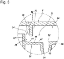
Figure 3 is an enlarged sectional view of a main part of the oil separator; -
Figure 4 is a conceptual view illustrating the operation of the oil separator; and -
Figure 5 is a conceptual view illustrating the operation of an oil separator of a modified embodiment. - An embodiment of the present invention is described in the following with reference to the appended drawings. The terms indicating various directions in the following description are defined on the basis of the respective drawings.
- In a blow-by recirculation system of an automotive engine not shown in the drawings, an
oil separator 2 is used for separating oil (oil particles) from the blow-by gas, and is provided integrally with or separately from a head cover provided in an upper part of the engine. - Referring to
Figures 1 and2 , theoil separator 2 includes a case 4 internally formed with an inlet 6 for introducing blow-by gas, apre-separator unit 8 for removing oil particles of relatively small sizes, apost-separator unit 10 for removing oil particles of relatively large sizes, and anoutlet 12 for expelling the blow-gas to outside, in that order from left (upstream side) to right (downstream side). The case 4 is further formed with anoil return system 14 for returning the oil collected in thepre-separator unit 8 and thepost-separator unit 10 to a crankcase chamber not shown in the drawings. The case 4 may be made of plastic or metallic material, and is provided with a generally rectangular configuration. - The inlet 6 communicates with the crankcase chamber so that the blow-by gas in the crankcase chamber is introduced into the
pre-separator unit 8. - The
pre-separator unit 8 includes aninlet part 16 for admitting the blow-by gas introduced from the inlet 6, anupstream passage 18 for accelerating the blow-by gas from theinlet part 16 in a prescribed direction, adownstream passage 20 for separating oil particles from the accelerated blow-by gas, acommunication part 22 for conducting the blow-by gas from thedownstream passage 20 to thepost-separator unit 10, and adrain 24 forming theoil return system 14 on the side of thepre-separator unit 8. The passage for the blow-by gas in thepre-separator unit 8 is defined by a pair ofcase side walls 26 and a plurality of fixed walls extending between the twocase side walls 26. - Referring to
Figure 3 , theupstream passage 18 is defined by arear wall 28 and afront wall 30 extending between the twocase side walls 26. Therear wall 28 extends vertically from the bottom surface of the case 4 so as to have a major plane generally facing the fore and aft direction. The free end of therear wall 28 opposes the inner surface of the upper wall of the case 4 at a certain gap. Thefront wall 30 is positioned in front of therear wall 28 or horizontally downstream of therear wall 28 with respect to the flow of the blow-by gas, and projects vertically downward from the inner surface of the upper wall of the case 4 so as to have a major plane generally facing the fore and aft direction. The free end of therear wall 28 and the free end of thefront wall 30 oppose each other. Arear surface 32 of thefront wall 30 defining a part of theupstream passage 18 is planar, and extending substantially in the vertical direction, but may also be slanted in the forward direction toward the lower end thereof. A rectangular annular passage defined by the twocase side walls 26, the free end side of therear wall 28 and the free end side of thefront wall 30 defines a narrowedportion 34 which is narrowed relative to the parts that are immediately upstream and downstream of the narrowedportion 34. - The
downstream passage 20 adjoins the lower end of theupstream passage 18. A part of thedownstream passage 20 is defined by aseparation wall 36 that changes the flow direction of the blow-by gas which has passed through theupstream passage 18 by about 90 degrees. Theseparation wall 36 extends from an intermediate part of afront surface 38 of therear wall 28 in the forward direction so as to have a wall surface generally facing upward. The extending direction of theseparation wall 36 is substantially orthogonal to therear wall 28. The upper surface of theseparation wall 36 opposes the free end of thefront wall 30 at a certain gap. The upper surface of theseparation wall 36 consists of afirst surface 40 on the upstream side and asecond surface 42 on the downstream side. - The
first surface 40 of theseparation wall 36 is planar, and forms an obtuse angle relative to theupstream passage 18. In other words, a plane defined by the extension of each of thefront surface 38 of therear wall 28 and therear surface 32 of thefront wall 30 forms an obtuse angle with respect to a plane of thefirst surface 40 of theseparation wall 36 extending from the intersection line between the corresponding plane in the downstream direction. Also, thefirst surface 40 extends further in the downstream direction than the intersection line between thefirst surface 40 and the extension plane of therear surface 32 of thefront wall 30. In other words, theboundary line 44 between thefirst surface 40 and thesecond surface 42 is located more downstream than the intersection line between theseparation wall 36 and the extension plane of therear surface 32 of thefront wall 30. Thesecond surface 42 of theseparation wall 36 is planar, and adjoins the downstream end of thefirst surface 40. Thesecond surface 42 is substantially horizontal, but may also slant slightly downward toward the downstream side thereof. The angle formed between thefirst surface 40 and thesecond surface 42 may be in the range of 135 to 177 degrees. In other words, the extension plane drawn from thesecond surface 42 in the upstream direction may form an angle of 3 to 45 degrees with respect to thesecond surface 42. Theboundary line 44 extends linearly in a direction orthogonal to the paper sheet ofFigure 3 . Therefore, the extension plane of thesecond surface 42 is substantially orthogonal to the extension direction of theupstream passage 18, and thefirst surface 40 is deflected with respect to thesecond surface 42 so as to be closer to theupstream passage 18 than the extension plane of thesecond surface 42. - A
drain 24 is provided immediately downstream of theseparation wall 36 in a downwardly extending manner for returning the oil separated from the blow-by gas to the crankcase chamber. Thedrain 24 is tubular in shape, and extends vertically. A steppedwall 50 having a major plane which is substantially orthogonal to the flow passage of the blow-by gas rises upward immediately downstream of thedrain 24. The upper end of the steppedwall 50 protrudes slightly upward than the extension plane of thesecond surface 42 of theseparation wall 36 so that a steppedsurface 52 higher than thesecond surface 42 is formed. The upper end of the steppedsurface 52 is lower than the free end of therear wall 28 and the free end of thefront wall 30. Thedrain 24 is connected to thesecond surface 42 and the steppedsurface 52 via smooth wall surfaces, and are positioned such that the oil that has deposited on thesecond surface 42 and the steppedsurface 52 flows into thedrain 24 owing to the flow of the blow-by gas or the gravitational force. - The lower end of the
drain 24 is received in arecess 54 in a spaced apart relationship, and agroove 56 is formed adjacent to therecess 54 so that the oil overflowing from therecess 54 is returned to the crankcase chamber via thegroove 56. Therecess 54 and thegroove 56 are formed so as to have upper opening planes that are at a same elevation. - The
communication part 22 is located on the downstream side of the steppedsurface 52 in order to conduct the blow-by gas to thepost-separator unit 10. Thecommunication part 22 is defined by abottom wall 58 extending in the downstream direction from the steppedsurface 52, and the upper wall and other parts of the case 4 located more forward than thefront wall 30. The upper surface of thebottom wall 58 slants downward toward the front part thereof. - The
inlet part 16 and thecommunication part 22 are provided with sub drains 60 and 62 for expelling the oil separated in theinlet part 16 and thecommunication part 22, respectively. Therear wall 28 stands upright from a part immediately downstream of thesub drain 60 of theinlet part 16. Thesub drain 62 of thecommunication part 22 is located in front of thebottom wall 58. The sub drains 60 and 62 are tubular in shape, and extend vertically with the lower ends received inrespective recesses 54 in a spaced apart relationship, similarly as thedrain 24. Theserecesses 54 receiving the sub drains 60 and 62 also adjoined by thegroove 56. - The
post-separator unit 10 receives the blow-by gas that has passed through thepre-separator unit 8, and removes primarily oil particles of smaller sizes than those separated by thepre-separator unit 8. - As shown in
Figure 2 , in thepost-separator unit 10, the flow passage is forked into four parallel branch passages each having a small oil particleremovable mechanism 64 of a substantially same structure. The blow-by gas flows substantially downward through the small oil particleremovable mechanisms 64. The branch passages merge into a single flow passage so that the blow-by gas that has passed through the small oil particleremovable mechanisms 64 merges into a single flow. - Referring to
Figure 2 , each small oil particleremovable mechanism 64 includes a vertically extendingcylinder 66, avalve member 68 vertically moveably received in thecylinder 66, asupport member 70 vertically moveably supporting thevalve member 68, and aspring member 72 urging thevalve member 68 upward. Arecovery groove 74 serving as a part of theoil return system 14 is provided under each small oil particleremovable mechanism 64. - The mode of operation of the
oil separator 2 is described in the following. As shown inFigure 4 , in thepre-separator unit 8, the oil particles in the blow-by gas is separated primarily by theseparation wall 36 and the steppedsurface 52. The arrows inFigure 4 indicate the flow of the blow-by gas. - The blow-by gas that has flowed into the
upstream passage 18 from theinlet part 16 is accelerated by the narrowedportion 34, and is directed downward or in a forwardly downward direction. It is believed that, owing to the presence of thefirst surface 40 forming an obtuse angle relative to theupstream passage 18 and thesecond surface 42 of theseparation wall 36, the blow-by gas is directed smoothly in the direction extending along thesecond surface 42 without being disturbed while the flow speed thereof is substantially maintained during this process. However, this theory should not be construed as limiting the present invention. At this time, the oil particles of relatively large sizes which have greater masses than other components of the blow-by gas are directed more downward than the other components. As a result, the oil particles of relatively large sizes collide with thesecond surface 42, and separated by being trapped by thesecond surface 42. The oil A separated on thesecond surface 42 flows into thedrain 24 by being pushed by the flow of the blow-by gas or under its own weight. - The blow-by gas that has flowed along the
second surface 42 is deflected upward owing to the presence of the steppedsurface 52 located on the downstream side thereof. The oil particles of relatively large sizes which failed to be separated by theseparation wall 36 collide with the steppedsurface 52, and are separated from the blow-by gas by being trapped by the steppedsurface 52 because the oil particles have a greater mass than the other components of the blow-by gas, and are hence subjected to a greater inertia. The oil B separated by the steppedsurface 52 flows into thedrain 24 under its own weight. - The oil A and B trapped by the
second surface 42 and the steppedsurface 52 is passed into thedrain 24, and is thence returned to the crankcase chamber via therecess 54 and thegroove 56. Also, similarly as the conventional labyrinth oil separator, oil is separated by being deposited on the wall surfaces of theinlet part 16 and thecommunication part 22 and dropping to the bottom under its own weight, and the separated oil is returned to the crankcase chamber via the sub drains 60 and 62, therecesses 54 and thegroove 56. - As shown in
Figure 2 , in thepost-separator unit 10, when a pressure difference between the crankcase chamber side and the intake system side becomes significant, the pressure difference overcomes the biasing force of thespring member 72 so that thevalve member 68 moves downward until the upper end surface of thevalve member 68 is displaced away from the shoulder surface defined on the upstream side of thecylinder 66, thereby opening the passage for the blow-by gas. - The blow-by gas traveling at high speed after passing through the gap between the upper end surface of the
valve member 68 and the shoulder surface in the upper end part of thecylinder 66 collides with the inner circumferential surface of thecylinder 66. The speed of the blow-by gas that collides with the inner circumferential surface of thecylinder 66 is far greater than that of the blow-by gas in thepre-separator unit 8. Therefore, even the oil particles of relatively small sizes can be trapped on the inner circumferential surface of thecylinder 66 owing to the inertia thereof. The blow-by gas that has passed through thecylinder 66 flows to theoutlet 12 while the oil trapped on the inner circumferential surface of thecylinder 66 drops into therecovery groove 74 located below to be returned to the crankcase chamber. - As the
pre-separator unit 8 is designed to separate oil particles of relatively large sizes, the narrowedportion 34 is wide enough not to be clogged by oil. As the flow passage of thepre-separator unit 8 is defined solely by fixed walls, and moving parts which are prone to failure are not used, there is no risk of failure. By suitably selecting the sizes and positions of the narrowedportion 34, theseparation wall 36 and the steppedsurface 52, oil particles greater than a prescribed size can be substantially entirely separated from the blow-by gas. Also, only one set of the narrowedportion 34, theseparation wall 36 and the steppedsurface 52 is required to be provided in thepre-separator unit 8 for oil particles having sizes greater than a prescribed size to be substantially entirely eliminated. Therefore, the pressure loss of the blow-by gas can be minimized, the length of the flow passage for the blow-by gas can be minimized, and the size of theoil separator 2 can be minimized. - Because the oil particles of large sizes have been trapped by the
pre-separator unit 8, thepost-separator unit 10 is required to trap only the oil particles of large sizes. Therefore, even when the flow passage is narrowed so as to accelerate the flow of the blow-by gas, clogging of the flow passage by the oil can be avoided or minimized. - A modified embodiment of the present invention is described in the following with reference to
Figure 5 . In the following description, the parts corresponding to those of the foregoing embodiment are denoted with like numerals without necessarily repeating the description of such parts. The modified embodiment differs from the foregoing embodiment only in the configuration of thefirst surface 78 of theseparation wall 76. - The
first surface 78 consists of a concave curved surface which is connected to therear wall 28 at aboundary line 80 and thesecond surface 42 at aboundary line 44. In the cross sectional view ofFigure 5 , the tangential line of thesurface 78 at theboundary line 80 with therear wall 28 drawn in the downstream direction forms an obtuse angle relative to the upstream passage 18 (seeFigure 3 ). The tangential line of thefirst surface 78 at theboundary line 44 with thesecond surface 42 substantially coincides with the extending direction of thesecond surface 42. - Regarding this modified embodiment also, it is believed that, owing to the presence of the
first surface 78 forming an obtuse angle relative to theupstream passage 18 and connected to thesecond surface 42 of theseparation wall 36 in a smoothly continuous manner, the blow-by gas is directed smoothly in the direction extending along thesecond surface 42 without being disturbed while the flow speed thereof is substantially maintained during this process, However, this theory should not be construed as limiting the present invention. At this time, the oil particles of relatively large sizes which have greater masses than other components of the blow-by gas are directed more downward than the other components. As a result, the oil particles of relatively large sizes collide with thesecond surface 42, and are separated by being trapped by thesecond surface 42 owing to the action of the inertia. - Although the present invention has been described in terms of a preferred embodiment thereof, it is obvious to a person skilled in the art that various alterations and modifications are possible without departing from the scope of the present invention. For instance, the pre-separator unit may also be used as an independent oil separator. The orientation of the oil separator is not limited by the illustrated embodiment, but may be altered freely as long as the separated oil is conducted to the drain under its own weight or by the flow of the blow-by gas. Instead of providing the narrowed portion in the upstream passage, the cross sectional area of the upstream passage may be made substantially constant from the inlet onward.
-
GLOSSARY OF TERMS 2 oil separator 8 pre-separator unit 18 upstream passage 20 downstream passage 24 drain 28 rear wall 30 front wall 32 rear surface of front wall 36, 37 separation wall 40, 78 first surface 42 second surface 44 boundary line between first surface and second surface 52 stepped surface
Claims (6)
- An oil separator for removing oil from blow-by gas of an internal combustion engine, comprising:a blow-by gas passage including an upstream passage and a downstream passage connected to a downstream end of the upstream passage and provided with a separation wall for changing a flow direction of the blow-by gas that has passed through the upstream passage;wherein the separation wall includes a first surface opposing the upstream passage, and a second surface adjoining the first surface on a downstream side thereof and defining a planar surface extending substantially perpendicularly to the upstream passage,the first surface defining a planar surface or a concave curved surface more proximate to the upstream passage than a planar extension of the second surface.
- The oil separator according to claim 1, wherein the upstream passage includes a pair of side walls having mutually opposing wall surfaces, a rear wall extending to the separation wall and a front wall having a free end opposing the separation wall at a gap, a boundary line between the first surface and the second surface being located more downstream than an intersection line between the separation wall and an extension plane of a rear surface of the front wall.
- The oil separator according to claim 2, wherein, the upstream passage extends vertically, and the second surface of the separation wall positioned below the upstream passage extends substantially horizontally or with a slight downward slant.
- The oil separator according to claim 3, further including a drain provided adjacent to a downstream side of the second surface for returning the oil separated from the blow-by gas by the separation wall to a crankcase chamber.
- The oil separator according to claim 4, further including a stepped surface extending substantially perpendicularly to an extension plane of the second surface on a downstream side of the drain, and projecting more inward into the downstream passage than the second surface.
- The oil separator according to claim 5, wherein the stepped surface is provided immediately downstream of and above the drain.
Applications Claiming Priority (2)
| Application Number | Priority Date | Filing Date | Title |
|---|---|---|---|
| JP2014205571A JP6236373B2 (en) | 2014-10-06 | 2014-10-06 | Oil separator |
| PCT/JP2015/003998 WO2016056159A1 (en) | 2014-10-06 | 2015-08-07 | Oil separator |
Publications (3)
| Publication Number | Publication Date |
|---|---|
| EP3205851A1 true EP3205851A1 (en) | 2017-08-16 |
| EP3205851A4 EP3205851A4 (en) | 2018-06-13 |
| EP3205851B1 EP3205851B1 (en) | 2020-12-02 |
Family
ID=55652807
Family Applications (1)
| Application Number | Title | Priority Date | Filing Date |
|---|---|---|---|
| EP15849253.8A Not-in-force EP3205851B1 (en) | 2014-10-06 | 2015-08-07 | Oil separator |
Country Status (5)
| Country | Link |
|---|---|
| US (1) | US10156169B2 (en) |
| EP (1) | EP3205851B1 (en) |
| JP (1) | JP6236373B2 (en) |
| CN (1) | CN106795788B (en) |
| WO (1) | WO2016056159A1 (en) |
Families Citing this family (1)
| Publication number | Priority date | Publication date | Assignee | Title |
|---|---|---|---|---|
| JP6729333B2 (en) * | 2016-12-06 | 2020-07-22 | 三菱自動車工業株式会社 | Cylinder head cover and engine equipped with the same |
Family Cites Families (16)
| Publication number | Priority date | Publication date | Assignee | Title |
|---|---|---|---|---|
| JPH1026012A (en) * | 1996-07-10 | 1998-01-27 | Hino Motors Ltd | Oil separator for engine |
| DE10127819A1 (en) | 2001-06-07 | 2003-01-02 | Bosch Gmbh Robert | Oil separator for crankcase gases of an internal combustion engine |
| DE10320215B4 (en) | 2003-05-05 | 2005-04-21 | Dichtungstechnik G. Bruss Gmbh & Co. Kg | Oil separation unit for blow by gas of an internal combustion engine comprises a separator element with at least one passage in the form of a long narrow gap whose width is alterable |
| US7080636B2 (en) | 2003-05-05 | 2006-07-25 | Dichtungstechnik G. Bruss Gmbh & Co. Kg | Oil separating device for a combustion engine |
| JP2005048601A (en) * | 2003-07-29 | 2005-02-24 | Kojima Press Co Ltd | Cylinder head cover structure |
| FR2874646B1 (en) * | 2004-08-27 | 2006-10-06 | Coutier Moulage Gen Ind | DESHUILEUR FOR INTERNAL COMBUSTION ENGINE |
| DE102004061938B3 (en) * | 2004-12-22 | 2006-06-29 | Dichtungstechnik G. Bruss Gmbh & Co. Kg | Oil separating system for internal combustion engine e.g. Otto engine, has oil separator for oil that is separated from blow-by-gases in crank case, and pressure control valve to control pressure in crank case |
| JP2007100567A (en) | 2005-10-03 | 2007-04-19 | Nissan Diesel Motor Co Ltd | Gas-oil separator of blow-by gas |
| US7383829B2 (en) * | 2006-02-09 | 2008-06-10 | Toyota Motor Engineering & Manufacturing North America, Inc. | Oil drain device for an engine oil separator |
| JP4690257B2 (en) | 2006-06-23 | 2011-06-01 | 株式会社マーレ フィルターシステムズ | Oil mist separator |
| DE102006041213B4 (en) | 2006-09-02 | 2017-06-29 | Mahle International Gmbh | Device for crank chamber ventilation |
| DE102007008672A1 (en) | 2007-02-20 | 2008-09-04 | Dichtungstechnik G. Bruss Gmbh & Co. Kg | Cylinder head cover for an internal combustion engine |
| EP2390477B1 (en) * | 2010-05-26 | 2012-12-05 | Fiat Powertrain Technologies S.p.A. | Separator device for a system for recirculation of the blow-by gases of an internal combustion engine |
| KR101335763B1 (en) | 2011-11-16 | 2013-12-02 | 인지컨트롤스 주식회사 | Separator for internal-combustion engine |
| JP2013133779A (en) * | 2011-12-27 | 2013-07-08 | Sanoh Industrial Co Ltd | Blowby gas recirculation device |
| EP2653678B1 (en) * | 2012-04-19 | 2015-05-20 | Fiat Powertrain Technologies S.p.A. | Separator device for use in a system for the recirculation of blow-by gases of an internal combustion engine |
-
2014
- 2014-10-06 JP JP2014205571A patent/JP6236373B2/en active Active
-
2015
- 2015-08-07 EP EP15849253.8A patent/EP3205851B1/en not_active Not-in-force
- 2015-08-07 CN CN201580054222.4A patent/CN106795788B/en active Active
- 2015-08-07 WO PCT/JP2015/003998 patent/WO2016056159A1/en not_active Ceased
- 2015-08-07 US US15/515,203 patent/US10156169B2/en active Active
Also Published As
| Publication number | Publication date |
|---|---|
| WO2016056159A1 (en) | 2016-04-14 |
| US10156169B2 (en) | 2018-12-18 |
| JP2016075199A (en) | 2016-05-12 |
| CN106795788A (en) | 2017-05-31 |
| CN106795788B (en) | 2019-04-26 |
| US20170218804A1 (en) | 2017-08-03 |
| EP3205851B1 (en) | 2020-12-02 |
| JP6236373B2 (en) | 2017-11-22 |
| EP3205851A4 (en) | 2018-06-13 |
Similar Documents
| Publication | Publication Date | Title |
|---|---|---|
| JP5847445B2 (en) | Oil separator for internal combustion engine | |
| JP5954333B2 (en) | Oil mist separator | |
| JP5899378B2 (en) | Head cover baffle system to improve oil mist separation | |
| JP2009121281A (en) | Oil separator for internal combustion engine | |
| US20160376950A1 (en) | Blow-by gas oil separator | |
| JP6181058B2 (en) | Method and apparatus for oil decantation in gas flow | |
| EP1870571A2 (en) | Oil mist separator | |
| CN102297002A (en) | Oil separation device of engine | |
| US10145278B2 (en) | Blow-by gas passage structure | |
| US9598991B2 (en) | Oil separator | |
| EP3205851B1 (en) | Oil separator | |
| US10661210B2 (en) | Oil separator including spiral members defining helical flow paths | |
| WO2012057203A1 (en) | Oil separator unit and oil separator structure | |
| JP6359962B2 (en) | Oil separator | |
| GB2078561A (en) | Horizontal vapour-liquid separator | |
| JPH08270430A (en) | Oil separator structure of internal combustion engine | |
| KR102271134B1 (en) | Array of staggered arrays for air/liquid separation | |
| KR101327058B1 (en) | Apparatus for separating blow by gas and engine oil of vehicle engine and ventilation structure of blow by gas | |
| US20190178122A1 (en) | Oil Separators | |
| JP6284904B2 (en) | Oil separator | |
| JP2017020761A (en) | Oil separator / collector | |
| US20180142587A1 (en) | Oil separation device for internal combustion engine | |
| US20160090882A1 (en) | Breather device for engine | |
| JP5223728B2 (en) | Oil mist separator | |
| JP5997513B2 (en) | Oil separator |
Legal Events
| Date | Code | Title | Description |
|---|---|---|---|
| STAA | Information on the status of an ep patent application or granted ep patent |
Free format text: STATUS: THE INTERNATIONAL PUBLICATION HAS BEEN MADE |
|
| PUAI | Public reference made under article 153(3) epc to a published international application that has entered the european phase |
Free format text: ORIGINAL CODE: 0009012 |
|
| STAA | Information on the status of an ep patent application or granted ep patent |
Free format text: STATUS: REQUEST FOR EXAMINATION WAS MADE |
|
| 17P | Request for examination filed |
Effective date: 20170424 |
|
| AK | Designated contracting states |
Kind code of ref document: A1 Designated state(s): AL AT BE BG CH CY CZ DE DK EE ES FI FR GB GR HR HU IE IS IT LI LT LU LV MC MK MT NL NO PL PT RO RS SE SI SK SM TR |
|
| AX | Request for extension of the european patent |
Extension state: BA ME |
|
| DAV | Request for validation of the european patent (deleted) | ||
| DAX | Request for extension of the european patent (deleted) | ||
| A4 | Supplementary search report drawn up and despatched |
Effective date: 20180516 |
|
| RIC1 | Information provided on ipc code assigned before grant |
Ipc: F01M 13/04 20060101AFI20180508BHEP Ipc: F01M 13/00 20060101ALI20180508BHEP Ipc: F01M 11/08 20060101ALI20180508BHEP Ipc: F01M 13/02 20060101ALI20180508BHEP |
|
| GRAP | Despatch of communication of intention to grant a patent |
Free format text: ORIGINAL CODE: EPIDOSNIGR1 |
|
| STAA | Information on the status of an ep patent application or granted ep patent |
Free format text: STATUS: GRANT OF PATENT IS INTENDED |
|
| RIC1 | Information provided on ipc code assigned before grant |
Ipc: F01M 11/08 20060101ALI20200728BHEP Ipc: F01M 13/04 20060101AFI20200728BHEP Ipc: F01M 13/02 20060101ALI20200728BHEP Ipc: F01M 13/00 20060101ALI20200728BHEP |
|
| INTG | Intention to grant announced |
Effective date: 20200827 |
|
| GRAS | Grant fee paid |
Free format text: ORIGINAL CODE: EPIDOSNIGR3 |
|
| GRAA | (expected) grant |
Free format text: ORIGINAL CODE: 0009210 |
|
| STAA | Information on the status of an ep patent application or granted ep patent |
Free format text: STATUS: THE PATENT HAS BEEN GRANTED |
|
| AK | Designated contracting states |
Kind code of ref document: B1 Designated state(s): AL AT BE BG CH CY CZ DE DK EE ES FI FR GB GR HR HU IE IS IT LI LT LU LV MC MK MT NL NO PL PT RO RS SE SI SK SM TR |
|
| REG | Reference to a national code |
Ref country code: GB Ref legal event code: FG4D |
|
| REG | Reference to a national code |
Ref country code: AT Ref legal event code: REF Ref document number: 1341162 Country of ref document: AT Kind code of ref document: T Effective date: 20201215 Ref country code: CH Ref legal event code: EP |
|
| REG | Reference to a national code |
Ref country code: DE Ref legal event code: R096 Ref document number: 602015063034 Country of ref document: DE |
|
| REG | Reference to a national code |
Ref country code: IE Ref legal event code: FG4D |
|
| PG25 | Lapsed in a contracting state [announced via postgrant information from national office to epo] |
Ref country code: GR Free format text: LAPSE BECAUSE OF FAILURE TO SUBMIT A TRANSLATION OF THE DESCRIPTION OR TO PAY THE FEE WITHIN THE PRESCRIBED TIME-LIMIT Effective date: 20210303 Ref country code: NO Free format text: LAPSE BECAUSE OF FAILURE TO SUBMIT A TRANSLATION OF THE DESCRIPTION OR TO PAY THE FEE WITHIN THE PRESCRIBED TIME-LIMIT Effective date: 20210302 Ref country code: FI Free format text: LAPSE BECAUSE OF FAILURE TO SUBMIT A TRANSLATION OF THE DESCRIPTION OR TO PAY THE FEE WITHIN THE PRESCRIBED TIME-LIMIT Effective date: 20201202 Ref country code: RS Free format text: LAPSE BECAUSE OF FAILURE TO SUBMIT A TRANSLATION OF THE DESCRIPTION OR TO PAY THE FEE WITHIN THE PRESCRIBED TIME-LIMIT Effective date: 20201202 |
|
| REG | Reference to a national code |
Ref country code: NL Ref legal event code: MP Effective date: 20201202 |
|
| REG | Reference to a national code |
Ref country code: AT Ref legal event code: MK05 Ref document number: 1341162 Country of ref document: AT Kind code of ref document: T Effective date: 20201202 |
|
| PG25 | Lapsed in a contracting state [announced via postgrant information from national office to epo] |
Ref country code: PL Free format text: LAPSE BECAUSE OF FAILURE TO SUBMIT A TRANSLATION OF THE DESCRIPTION OR TO PAY THE FEE WITHIN THE PRESCRIBED TIME-LIMIT Effective date: 20201202 Ref country code: SE Free format text: LAPSE BECAUSE OF FAILURE TO SUBMIT A TRANSLATION OF THE DESCRIPTION OR TO PAY THE FEE WITHIN THE PRESCRIBED TIME-LIMIT Effective date: 20201202 Ref country code: LV Free format text: LAPSE BECAUSE OF FAILURE TO SUBMIT A TRANSLATION OF THE DESCRIPTION OR TO PAY THE FEE WITHIN THE PRESCRIBED TIME-LIMIT Effective date: 20201202 Ref country code: BG Free format text: LAPSE BECAUSE OF FAILURE TO SUBMIT A TRANSLATION OF THE DESCRIPTION OR TO PAY THE FEE WITHIN THE PRESCRIBED TIME-LIMIT Effective date: 20210302 |
|
| PG25 | Lapsed in a contracting state [announced via postgrant information from national office to epo] |
Ref country code: NL Free format text: LAPSE BECAUSE OF FAILURE TO SUBMIT A TRANSLATION OF THE DESCRIPTION OR TO PAY THE FEE WITHIN THE PRESCRIBED TIME-LIMIT Effective date: 20201202 Ref country code: HR Free format text: LAPSE BECAUSE OF FAILURE TO SUBMIT A TRANSLATION OF THE DESCRIPTION OR TO PAY THE FEE WITHIN THE PRESCRIBED TIME-LIMIT Effective date: 20201202 |
|
| REG | Reference to a national code |
Ref country code: LT Ref legal event code: MG9D |
|
| PG25 | Lapsed in a contracting state [announced via postgrant information from national office to epo] |
Ref country code: SM Free format text: LAPSE BECAUSE OF FAILURE TO SUBMIT A TRANSLATION OF THE DESCRIPTION OR TO PAY THE FEE WITHIN THE PRESCRIBED TIME-LIMIT Effective date: 20201202 Ref country code: CZ Free format text: LAPSE BECAUSE OF FAILURE TO SUBMIT A TRANSLATION OF THE DESCRIPTION OR TO PAY THE FEE WITHIN THE PRESCRIBED TIME-LIMIT Effective date: 20201202 Ref country code: EE Free format text: LAPSE BECAUSE OF FAILURE TO SUBMIT A TRANSLATION OF THE DESCRIPTION OR TO PAY THE FEE WITHIN THE PRESCRIBED TIME-LIMIT Effective date: 20201202 Ref country code: RO Free format text: LAPSE BECAUSE OF FAILURE TO SUBMIT A TRANSLATION OF THE DESCRIPTION OR TO PAY THE FEE WITHIN THE PRESCRIBED TIME-LIMIT Effective date: 20201202 Ref country code: SK Free format text: LAPSE BECAUSE OF FAILURE TO SUBMIT A TRANSLATION OF THE DESCRIPTION OR TO PAY THE FEE WITHIN THE PRESCRIBED TIME-LIMIT Effective date: 20201202 Ref country code: PT Free format text: LAPSE BECAUSE OF FAILURE TO SUBMIT A TRANSLATION OF THE DESCRIPTION OR TO PAY THE FEE WITHIN THE PRESCRIBED TIME-LIMIT Effective date: 20210405 Ref country code: LT Free format text: LAPSE BECAUSE OF FAILURE TO SUBMIT A TRANSLATION OF THE DESCRIPTION OR TO PAY THE FEE WITHIN THE PRESCRIBED TIME-LIMIT Effective date: 20201202 |
|
| PG25 | Lapsed in a contracting state [announced via postgrant information from national office to epo] |
Ref country code: AT Free format text: LAPSE BECAUSE OF FAILURE TO SUBMIT A TRANSLATION OF THE DESCRIPTION OR TO PAY THE FEE WITHIN THE PRESCRIBED TIME-LIMIT Effective date: 20201202 |
|
| REG | Reference to a national code |
Ref country code: DE Ref legal event code: R097 Ref document number: 602015063034 Country of ref document: DE |
|
| PG25 | Lapsed in a contracting state [announced via postgrant information from national office to epo] |
Ref country code: IS Free format text: LAPSE BECAUSE OF FAILURE TO SUBMIT A TRANSLATION OF THE DESCRIPTION OR TO PAY THE FEE WITHIN THE PRESCRIBED TIME-LIMIT Effective date: 20210402 |
|
| PLBE | No opposition filed within time limit |
Free format text: ORIGINAL CODE: 0009261 |
|
| STAA | Information on the status of an ep patent application or granted ep patent |
Free format text: STATUS: NO OPPOSITION FILED WITHIN TIME LIMIT |
|
| PG25 | Lapsed in a contracting state [announced via postgrant information from national office to epo] |
Ref country code: AL Free format text: LAPSE BECAUSE OF FAILURE TO SUBMIT A TRANSLATION OF THE DESCRIPTION OR TO PAY THE FEE WITHIN THE PRESCRIBED TIME-LIMIT Effective date: 20201202 Ref country code: IT Free format text: LAPSE BECAUSE OF FAILURE TO SUBMIT A TRANSLATION OF THE DESCRIPTION OR TO PAY THE FEE WITHIN THE PRESCRIBED TIME-LIMIT Effective date: 20201202 |
|
| 26N | No opposition filed |
Effective date: 20210903 |
|
| PG25 | Lapsed in a contracting state [announced via postgrant information from national office to epo] |
Ref country code: DK Free format text: LAPSE BECAUSE OF FAILURE TO SUBMIT A TRANSLATION OF THE DESCRIPTION OR TO PAY THE FEE WITHIN THE PRESCRIBED TIME-LIMIT Effective date: 20201202 Ref country code: SI Free format text: LAPSE BECAUSE OF FAILURE TO SUBMIT A TRANSLATION OF THE DESCRIPTION OR TO PAY THE FEE WITHIN THE PRESCRIBED TIME-LIMIT Effective date: 20201202 |
|
| PG25 | Lapsed in a contracting state [announced via postgrant information from national office to epo] |
Ref country code: ES Free format text: LAPSE BECAUSE OF FAILURE TO SUBMIT A TRANSLATION OF THE DESCRIPTION OR TO PAY THE FEE WITHIN THE PRESCRIBED TIME-LIMIT Effective date: 20201202 |
|
| REG | Reference to a national code |
Ref country code: CH Ref legal event code: PL |
|
| PG25 | Lapsed in a contracting state [announced via postgrant information from national office to epo] |
Ref country code: MC Free format text: LAPSE BECAUSE OF FAILURE TO SUBMIT A TRANSLATION OF THE DESCRIPTION OR TO PAY THE FEE WITHIN THE PRESCRIBED TIME-LIMIT Effective date: 20201202 |
|
| REG | Reference to a national code |
Ref country code: BE Ref legal event code: MM Effective date: 20210831 |
|
| GBPC | Gb: european patent ceased through non-payment of renewal fee |
Effective date: 20210807 |
|
| PG25 | Lapsed in a contracting state [announced via postgrant information from national office to epo] |
Ref country code: LI Free format text: LAPSE BECAUSE OF NON-PAYMENT OF DUE FEES Effective date: 20210831 Ref country code: CH Free format text: LAPSE BECAUSE OF NON-PAYMENT OF DUE FEES Effective date: 20210831 |
|
| PG25 | Lapsed in a contracting state [announced via postgrant information from national office to epo] |
Ref country code: IS Free format text: LAPSE BECAUSE OF FAILURE TO SUBMIT A TRANSLATION OF THE DESCRIPTION OR TO PAY THE FEE WITHIN THE PRESCRIBED TIME-LIMIT Effective date: 20210402 Ref country code: LU Free format text: LAPSE BECAUSE OF NON-PAYMENT OF DUE FEES Effective date: 20210807 |
|
| PG25 | Lapsed in a contracting state [announced via postgrant information from national office to epo] |
Ref country code: IE Free format text: LAPSE BECAUSE OF NON-PAYMENT OF DUE FEES Effective date: 20210807 Ref country code: GB Free format text: LAPSE BECAUSE OF NON-PAYMENT OF DUE FEES Effective date: 20210807 Ref country code: FR Free format text: LAPSE BECAUSE OF NON-PAYMENT OF DUE FEES Effective date: 20210831 Ref country code: BE Free format text: LAPSE BECAUSE OF NON-PAYMENT OF DUE FEES Effective date: 20210831 |
|
| PG25 | Lapsed in a contracting state [announced via postgrant information from national office to epo] |
Ref country code: HU Free format text: LAPSE BECAUSE OF FAILURE TO SUBMIT A TRANSLATION OF THE DESCRIPTION OR TO PAY THE FEE WITHIN THE PRESCRIBED TIME-LIMIT; INVALID AB INITIO Effective date: 20150807 |
|
| PG25 | Lapsed in a contracting state [announced via postgrant information from national office to epo] |
Ref country code: CY Free format text: LAPSE BECAUSE OF FAILURE TO SUBMIT A TRANSLATION OF THE DESCRIPTION OR TO PAY THE FEE WITHIN THE PRESCRIBED TIME-LIMIT Effective date: 20201202 |
|
| PG25 | Lapsed in a contracting state [announced via postgrant information from national office to epo] |
Ref country code: MK Free format text: LAPSE BECAUSE OF FAILURE TO SUBMIT A TRANSLATION OF THE DESCRIPTION OR TO PAY THE FEE WITHIN THE PRESCRIBED TIME-LIMIT Effective date: 20201202 |
|
| PG25 | Lapsed in a contracting state [announced via postgrant information from national office to epo] |
Ref country code: TR Free format text: LAPSE BECAUSE OF FAILURE TO SUBMIT A TRANSLATION OF THE DESCRIPTION OR TO PAY THE FEE WITHIN THE PRESCRIBED TIME-LIMIT Effective date: 20201202 |
|
| PG25 | Lapsed in a contracting state [announced via postgrant information from national office to epo] |
Ref country code: MT Free format text: LAPSE BECAUSE OF FAILURE TO SUBMIT A TRANSLATION OF THE DESCRIPTION OR TO PAY THE FEE WITHIN THE PRESCRIBED TIME-LIMIT Effective date: 20201202 |
|
| PGFP | Annual fee paid to national office [announced via postgrant information from national office to epo] |
Ref country code: DE Payment date: 20240702 Year of fee payment: 10 |
|
| REG | Reference to a national code |
Ref country code: DE Ref legal event code: R119 Ref document number: 602015063034 Country of ref document: DE |