EP3205546A1 - Transition to be mounted between two vehicles with a jointed connection - Google Patents
Transition to be mounted between two vehicles with a jointed connection Download PDFInfo
- Publication number
- EP3205546A1 EP3205546A1 EP17154906.6A EP17154906A EP3205546A1 EP 3205546 A1 EP3205546 A1 EP 3205546A1 EP 17154906 A EP17154906 A EP 17154906A EP 3205546 A1 EP3205546 A1 EP 3205546A1
- Authority
- EP
- European Patent Office
- Prior art keywords
- transition
- closure element
- passage opening
- closure
- elements
- Prior art date
- Legal status (The legal status is an assumption and is not a legal conclusion. Google has not performed a legal analysis and makes no representation as to the accuracy of the status listed.)
- Withdrawn
Links
Images


Classifications
-
- B—PERFORMING OPERATIONS; TRANSPORTING
- B61—RAILWAYS
- B61D—BODY DETAILS OR KINDS OF RAILWAY VEHICLES
- B61D17/00—Construction details of vehicle bodies
- B61D17/04—Construction details of vehicle bodies with bodies of metal; with composite, e.g. metal and wood body structures
- B61D17/20—Communication passages between coaches; Adaptation of coach ends therefor
-
- A—HUMAN NECESSITIES
- A62—LIFE-SAVING; FIRE-FIGHTING
- A62C—FIRE-FIGHTING
- A62C2/00—Fire prevention or containment
- A62C2/06—Physical fire-barriers
- A62C2/12—Hinged dampers
- A62C2/14—Hinged dampers with two or more blades
- A62C2/16—Hinged dampers with two or more blades multi-vane roll or fold-up type
-
- A—HUMAN NECESSITIES
- A62—LIFE-SAVING; FIRE-FIGHTING
- A62C—FIRE-FIGHTING
- A62C3/00—Fire prevention, containment or extinguishing specially adapted for particular objects or places
- A62C3/07—Fire prevention, containment or extinguishing specially adapted for particular objects or places in vehicles, e.g. in road vehicles
-
- B—PERFORMING OPERATIONS; TRANSPORTING
- B60—VEHICLES IN GENERAL
- B60D—VEHICLE CONNECTIONS
- B60D5/00—Gangways for coupled vehicles, e.g. of concertina type
-
- B—PERFORMING OPERATIONS; TRANSPORTING
- B60—VEHICLES IN GENERAL
- B60D—VEHICLE CONNECTIONS
- B60D5/00—Gangways for coupled vehicles, e.g. of concertina type
- B60D5/003—Bellows for interconnecting vehicle parts
-
- B—PERFORMING OPERATIONS; TRANSPORTING
- B61—RAILWAYS
- B61D—BODY DETAILS OR KINDS OF RAILWAY VEHICLES
- B61D19/00—Door arrangements specially adapted for rail vehicles
- B61D19/02—Door arrangements specially adapted for rail vehicles for carriages
Definitions
- the present invention relates to a transition to the arrangement between two articulated vehicles, preferably rail vehicles, the transition comprising a device for containing a fire in a passenger compartment of the vehicle.
- the present invention compared to conventional fire doors to cause a significant reduction in space requirements in the vehicle.
- the essence of the present invention is to save space in the vehicle, in particular in the passenger area, by disposing a fire containment device in a gangway provided for placement between two articulated vehicles.
- a fire containment device in a gangway provided for placement between two articulated vehicles.
- the transition comprises a device for containing a fire in a passenger area of the vehicle.
- a device for containing a fire is to be understood as meaning a device which has the functionality required by Regulation (EU) 1302/2014. Such a device may also be referred to as a firewall.
- passenger area means not only that area of the vehicle intended primarily for passengers, but also that area of the vehicle in which personnel can reside.
- Transitions per se are known from the prior art. These usually have for attachment to car bodies at the ends of the articulated vehicles end frame. Typically, the end frames are bolted to the respective car body. In addition, the transitions may include at least one center frame located between the end frames. In order to mount the firewall in a simple manner in or at the transition, it is provided in a preferred embodiment of the transition according to the invention that the device is arranged on an end frame or on a middle frame of the transition.
- the device comprises at least one closure element which can be transferred from a first position to a second position and vice versa the at least one closure element completely fills a passage opening of the device in the first position and at least partially clears the passage opening in the second position to allow persons a passage that the at least one closure element is flexible and in the first position a course of the at least one Closure element in a horizontal sectional plane has a different curvature than in the second position.
- the at least one closure element runs along at least one line in the sectional plane, this line having a different curvature in the first position than in the second position.
- the flexibility of the at least one closure element is to be understood so that thereby different curvatures of the course are made possible. Since the at least one closure element is curved differently by its flexible design in the first and second positions, a particularly space-saving arrangement in the second position can be achieved.
- the course of the at least one closure element in the second position relative to the first position can represent a deflection with respect to an opening direction, wherein the opening direction is then automatically clearly defined if the course in the first position is rectilinear, since the opening direction is then parallel to the straight line which follows the course.
- the fire can then be reduced by transferring the at least one closure element from the second position to the first position be completely closed by the at least one closure element, the passage opening and thus the transition and forms a barrier to the fire.
- the device for this purpose is dimensioned so that the passage opening substantially corresponds to a cross section of the transition - and possibly the passenger area. That this cross-section can be reliably closed by means of the device according to the invention, if necessary.
- the entire movement of the at least one closure element takes place horizontally. That when transferring between the first and second positions, and vice versa, essentially only the horizontal coordinates of each point of the closure element change.
- the at least one closure element is arranged in its second position at least in sections on at least one side ("left and / or right") of the passage opening or the transition in which the device according to the invention is installed. In the first position, the at least one closure element then projects from this side.
- the at least one closure element Due to the flexible design of the at least one closure element, it can not only be deflected during the transition from the closed, first position to the open, second position, but the at least one closure element can be wound or rolled upright, which represents an extreme saving of space. Therefore, it is provided in a preferred embodiment of the transition according to the invention that in the sectional plane of the course in the first position, at least in the region of the passage opening is rectilinear and curved in the second position at least in a region outside the passage opening, preferably spirally.
- the straight-line course in the first position represents the The simplest and most economical way to completely close the passage opening or the transition.
- the passage opening lies in one plane.
- the cutting plane is normal to the plane of the passage opening, but in principle also an angle not equal to 90 ° between the cutting plane and the plane of the passage opening is possible if the plane of the passage opening with respect to a vertical plane is arranged inclined.
- a sufficient release of the through-opening in the second position can be realized in that the profile in the second position only covers a certain angular range around an axis. That It is not absolutely necessary for the at least one closure element to be wound up in the second position in several layers. Accordingly, it is provided in a preferred embodiment of the transition according to the invention that in the sectional plane of the course in the second position, a normal standing on the cutting plane axis over an angular range of at least 180 °, preferably at least 270 ° surrounds.
- the profile can be arranged at least partially spirally about the axis or about an intersection of the axis with the cutting plane or at least partially circular arc.
- the device comprises closing means which permanently exert a force on the at least one closure element to transfer this to the first position and / or to hold in the first position.
- the closing means are designed so that the force can be overcome by manual force, so that a person can manually convert the at least one closure element, against the force applied by the closing means, from the first position to the second position.
- mechanical closing means provide a cost effective solution to ensure reliable closing, even in cases where, for example, an electrical power supply is interrupted. Therefore, it is provided in a preferred embodiment of the transition according to the invention that the closing means comprise at least one spring and / or at least one counterweight.
- retaining means are provided to the at least one closure element to hold in the second position until the transfer to the first position is initiated.
- the initiation can be done by a fire message, the fire message can take place again in the form of a signal or a loss of a security signal.
- a failure of the power supply can initiate the closure of the passage opening.
- the initiation can of course also be carried out for other reasons, in particular if the passage opening is to be intentionally closed.
- the latter may in particular be the case when the transition completes the vehicle - the transition is thus not arranged in this case between two vehicles, but at the end of a vehicle - and the vehicle is put out of service.
- the closing of the passage opening can serve in this case to prevent unauthorized access to the interior of the vehicle from the outside, provided that the device or the firewall has an additional, intended and separately operated lock to the at least one closure element in the to block first position.
- the closed passage opening can be opened at any time by a person by simply pushing. That the person can transfer the at least one closure element from the first position to the second position. In case of fire, the person can thus open the firewall, wherein the at least one closure element, however, not locked in the second position, ie in the open state, but immediately behind the person is closed again by the closing means. This is necessary to prevent people being trapped in case of fire.
- the holding means comprise at least one magnet, preferably electromagnet.
- a permanent magnet When a permanent magnet is used, it can be brought, for example, electrically activated from a holding position in which the permanent magnet holds the at least one closure element in the second position due to its magnetic force into a release position in which the permanent magnet no longer holds the at least one closure element.
- electromagnets can its magnetic force is interrupted or sufficiently reduced by interrupting or reducing an electrical power supply, so that the electromagnet can no longer hold the at least one closure element by means of its magnetic force in the second position.
- the magnet can cooperate with a release element of the holding means, such as a release lever or a release plunger, the release element depending on its position block the at least one closure element in the second position or the transfer in can release the first position.
- the release element can be moved accordingly between these positions.
- the at least one closure element on opposite sides by means of guides is guided, wherein the guides predetermine the course of the at least one closure element in the cutting plane.
- the guides on opposite sides, typically above and below the at least one closure element, thereby guarantee a mechanically particularly stable arrangement of the at least one closure element both in the first and second position and in the transfer between these positions.
- the at least one closure element is guided in the guides by means of rollers and / or sliding elements.
- rollers and / or sliding elements For example, to guide the at least one closure element in an upper guide rollers, in particular support rollers may be provided which receive the majority of the weight load of the at least one closure element. Accordingly, in particular, portions of the closure element which are guided in a lower guide, may be designed so that they have optimum sliding properties in the lower guide.
- these sections can be made of a suitable material - such as polytetrafluoroethylene, polyamide or high molecular weight polyethylene or similar plastics with good sliding properties - or have a coating of such a material.
- the guides can be made of metal, in particular of an aluminum alloy or a steel alloy.
- intumescent material preferably an intumescent fire protection laminate
- intumescent materials or fire-resistant laminates are known from the prior art and are commercially available. These increase in the action of heat, in particular at temperatures which are greater than a release temperature of eg 150 ° C, their volume and thus form a heat-insulating layer, for example of a microporous foam. In addition, this layer can also function as a flue gas barrier.
- seals can be protected in case of fire, the u.a. serve to seal against flue gases when the at least one closure element is in the first position.
- the seals assume the sole sealing function against flue gases. This must be taken into account in the arrangement of the seals.
- the seals must preferably remain stable at least until reaching the triggering temperature.
- Such gaskets or materials suitable for such gaskets are generally known from the prior art, preferably using silicone or silicone-based materials.
- a seal in the region of the inner surface is arranged. That in particular, the seals can also be arranged on the inner surfaces of the guides and seal a region between the at least one closure element and the respective guide.
- the longitudinal axis is normal to the cutting plane and receive the at least one closure element from two opposite sides between them, wherein on an inner surface of the Subframe elements an intumescent material, preferably an intumescent fire protection laminate, is arranged.
- the subframe elements limit the passage opening at least in sections.
- seals can be protected in case of fire, which, among other things, to seal against Serve flue gases. Respectively. Such seals are necessary for sealing against flue gases, as long as the intumescent material has not yet expanded and thus has not yet formed a flue gas barrier. Therefore, it is provided in a particularly preferred embodiment of the transition according to the invention that seen in a direction away from the passage opening direction behind the intumescent material, a seal in the region of the inner surface of the subframe elements is arranged. That is, the seals can also be arranged on the inner surfaces of the subframe elements and seal a region between the at least one closure element and the subframe elements, in particular if the at least one closure element is in the first position.
- At least one synchronization shaft rotatable about a rotation axis normal to the cutting plane is provided , which is arranged outside the passage opening and connected to one end of the at least one closure element, wherein by rotation of the at least one synchronization shaft, the at least one closure element between the first position and the second position can be moved back and forth.
- a division of the force effects on the at least one closure element between the upper and lower guide can thereby be effected in order to counteract tilting in the guides.
- the axis of rotation can act as that axis about which the profile is arranged in the cutting plane in the second position and covers a certain angular range.
- the most direct possible transmission of force from the synchronization shaft to the at least one closure element is to be ensured in order to effect the transfer of the at least one closure element from the second position to the first position and back by reciprocating the synchronization shaft.
- a jerky action on the at least one closure element with the force transmitted by the synchronization shaft should be avoided in order to counteract tilting. Therefore, it is provided in a particularly preferred embodiment of the transition according to the invention that are provided for connecting the at least one synchronization shaft with the at least one closure element spring steel clips. Elastic deformation of the spring steel clips prevents or at least dampens jerky engagement of the force on the at least one closure element when the synchronization shaft is jerked in rotation.
- the closing means are operatively connected to the at least one synchronization shaft.
- the operative connection can take place in known ways, for example via gears and toothed belts, on gears alone or on sprockets and chains.
- the at least one closure element may e.g. consist of a refractory and mechanically relatively stiff fabric or a corresponding film.
- Such fabrics are known in the art and, to achieve the desired refractoriness, e.g. a silicone material or a silicone-based material.
- the at least one closure element is typically designed so that at least 15 minutes fire resistance is given.
- the at least one closure element is constructed of lamellae connected to one another in an articulated manner.
- the lamellae can basically be constructed of mechanically strong materials and accordingly be inflexible.
- the flexibility of the at least one closure element necessary for the device according to the invention is realized by the articulated connection of the lamellae.
- hinge joints can be provided as a connection.
- the hinge joints can be constructed in a conventional manner.
- the lamellae may be geometrically designed such that they each form a pincer-shaped joint cup on one side and a roller-shaped joint head on an opposite side.
- the lamellae are then connected to one another such that the joint head of a lamella is received in the joint socket of the subsequent lamella.
- the lamellae can consist of a solid shell, for example of a suitable hard plastic or an aluminum alloy, which is provided with a lighter material, for example a foam, for example a polyurethane foam, is filled.
- a lighter material for example a foam, for example a polyurethane foam
- the slats are filled with an intumescent material.
- the intumescent material forms a heat-insulating layer. That is, the at least one closure element then forms in the first position effective heat insulation of the passage opening, which further reduces the risk of fire flashover due to the action of heat through the closed passage opening.
- the two closure elements for transfer from the first position to the second position and vice versa at least partially movable in opposite directions.
- the transition according to the invention In order to achieve a particularly economical use of space, it is provided in a preferred embodiment of the transition according to the invention that are filled by the two closure elements in the first position substantially equal areas of the passage opening. Accordingly, the Space required for the accommodation of the two closure elements in their second position on the sides then substantially the same size, which simplifies the installation of the device according to the invention in the transition according to the invention constructively.
- the two closure elements have free ends which are in the first position with each other.
- the free ends at least in an intermediate position, which occupy the two closure elements in their transfer between the first position and the second position, are arranged opposite to each other.
- one of the two free ends at least partially has a groove and the other of the two free ends is at least partially formed as a counterpart to the groove, wherein in the first position, the groove and the counterpart in engagement stand.
- Such a design of the free ends allows the free ends can be reliably brought into engagement with each other by transferring into the first position.
- intumescent material preferably intumescent fire protection laminate
- intumescent material is arranged on mutually opposite inner surfaces of the groove.
- the free ends are protected by the intumescent material formed by heat insulating layer particularly effective against destructive heat exposure.
- seals can be protected in case of fire, the Seal against flue gases and are arranged in the groove when the closure elements are in the first position.
- Such seals are necessary for sealing against flue gases, as long as the intumescent material has not yet expanded and thus has not yet formed a flue gas barrier.
- the seals can be arranged both at the free end of a closure element and at the free end of the other closure element.
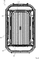
- Fig. 1 shows a device 1 according to the invention for containing a fire in a passenger area of a vehicle, in particular rail vehicle, which device 1 is provided for use in a transition 26 according to the invention.
- the device 1 on two closure elements 2a, 2b, which in Fig. 1 are shown in a first position 3, in which they a through hole 5 (see. Fig. 3 ) completely fill or close.
- a through hole 5 see. Fig. 3
- closure elements 2a, 2b can also be locked in the first position 3 in order to make a passage through the passage opening 5 impossible for persons.
- the closure elements 2a, 2b are constructed in the illustrated embodiment of lamellae 20 which are hinged together, resulting in a flexibility of the closure elements 2a, 2b results. This flexibility allows the closure elements 2a, 2b not be pushed or pivoted to release the through hole 5 as known rigid door leaves, but laterally the passage opening 5 can be arranged curved, thereby saving a considerable amount of space known solutions is achieved, which in turn allows the placement in a transition 26 of the invention.
- the closure elements 2a, 2b are located in a second position 4, in which the passage opening 5 is released.
- the course surrounds an axis of rotation 8 of a synchronization shaft 18 over an angular range of slightly more than 270 °. That is, the closure elements 2a, 2b are arranged in the second position 4 around the axes of rotation 8 and the synchronization shafts 18 or partially rolled up or wound up.
- the inventive device 1 can be easily arranged in a transition 26 according to the invention, which is provided for the arrangement between two articulated vehicles, preferably rail vehicles.
- Fig. 2 shows a transition 26 according to the invention with the device 1 according to the invention Fig. 1 , wherein the closure elements 2a, 2b are shown in the first position 3.
- the device 1 is dimensioned such that a cross section of the transition 26, which corresponds to a cross section of a passenger area of the vehicles, completely is closed in order to optimally contain a fire in the passenger area.
- This cross section of the transition 26 is surrounded in a conventional manner by an inner bellows 33.
- the transition 26 has an outer bellows 32 surrounding the inner bellows 33 in a manner known per se.
- the device 1 can be attached to such an end frame 28.
- the transition 26 to a middle frame 27, on which in the embodiment shown, the device 1 is attached.
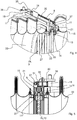
- an upper guide 11 of the device 1 is connected to the middle frame 27, as in 4 and FIG. 5 is clearly recognizable.
- the upper guide 11 is executed in the illustrated embodiment as a profile in which the individual blades 20 of the closure elements 2a, 2b are movable by means of support rollers 21 back and forth.
- the support rollers 21 transfer the majority of the weight of the slats 20 on the upper guide 11, wherein the support rollers 21 ensure a substantially frictionless movement in the upper guide 11.
- the closure elements 2a, 2b and the lamellae 20 are on their upper guide 11 opposite side in one bottom guide 12 out. Since the weight of the slats 20 is transmitted predominantly by the support rollers 21 on the upper guide 11, the lower guide 12 and the sections of the slats 20 arranged therein are designed as a sliding pair. For this purpose, these sections of the slats 20 may be coated in particular with a material which ensures the lowest possible sliding friction of the slats 20 in the lower guide 12.
- FIG. 8 A detailed view of the guided in the lower guide 12 slats 20 of the closure element 2a is in Fig. 8 shown, wherein the closure element 2a is in the first position 3.
- the articulated connection of the slats 20 can be seen through hinge joints 38.
- the lamellae 20 are geometrically designed such that they form a pincer-shaped joint cup of the hinge joint 38 on one side and a roller-shaped joint head of the hinge joint 38 on an opposite side.
- the lamellae 20 are connected to one another along the lower guide 12 Joint head of a blade 20 is received in the joint socket of the subsequent blade 20.
- the upper guide 11 and the lower guide 12 are parallel to each other and define by their course or their geometry the course 6 of the closure elements 2a, 2b in the first position 3 and second position 4. by the closure elements 2a, 2b are moved back and forth in the guides 11, 12, the closure elements 2a, 2b are transferred from the first position 3 to the second position 4 and back.
- the movement of the closure elements 2a, 2b takes place in the illustrated embodiment using the synchronization waves 18.
- the latter are about Spring steel clips 19 connected to the closure elements 2a, 2b.
- the spring steel clamps 19, in turn, are distributed uniformly over the synchronization shafts 18 as seen along the axes of rotation 8, so that a torque or force effect between the synchronization shafts 18 and the closure elements 2a, 2b is distributed uniformly along the axes of rotation 8. That is, between the upper guide 11 and the lower guide 12, there is a uniform force on the closure elements 2a, 2b, which effectively prevents tilting of the closure elements 2a, 2b in the guides 11, 12.
- the person must preferably overcome a force which is exerted by closing means permanently on the closure elements 2a, 2b, in order to transfer these into the first position 3 and / or to hold them in the first position 3.
- the closing means for each closure element 2a, 2b each comprise a spring 9, which in 4 and FIG. 5 is particularly well recognizable.
- the spring 9 is arranged above the upper guide 11 and guided by means of a linearly extending guide rod 37.
- the spring 9 is designed as a helical compression spring whose turns run around the guide rod 37.
- the spring 9 is supported at one end on a support member which is rigidly connected to the upper guide 11 and arranged upstanding from this. It can the support member be integral with the upper guide 11.
- the spring 9 is connected to a toothed belt 30.
- the toothed belt 30 preferably has a projecting pressure element against which the other end of the spring 9 presses, so that at least one frictional connection between the spring 9 and the pressure element or the toothed belt 30 is given.
- the toothed belt 30 is also disposed above the upper guide 11 and extends substantially parallel to the spring 9 and the upper guide 11.
- the toothed belt 30 extends between two gears 31 which are rotatably mounted on the upper guide 11, wherein axes of rotation of the gears 31st are arranged substantially parallel to the axis of rotation 8 of the synchronization shafts 18.
- One of the two gears 31 of each closure element 2a, 2b is arranged in the region of the respective synchronization shaft 18 and has a pinion 35, which is in engagement with a toothed wheel 36 of the synchronization shaft 18.
- the spring 9 with the associated synchronization shaft 18 is operatively connected , Conversely, of course, a movement of the closure element 2a, 2b causes a tensioning or relaxing of the spring 9. In particular, the spring 9 is tensioned when the respective closure element 2a, 2b is transferred from the first position 3 to the second position 4.
- a holding means in the form of an electromagnet 10 is provided for each closure element 2a, 2b with a release element in the form of a Release lever 42 cooperates.
- the electromagnet 10 and the release lever 42 serve to hold the respective closure element 2a, 2b in the second position 4 until the transfer to the first position 3 is initiated.
- the initiation can be done by a fire message, the fire message can take place again in the form of a signal or a loss of a security signal.
- the initiation can of course also be carried out for other reasons, in particular if the passage opening 5 is to be intentionally closed.
- the respective electromagnet 10 is arranged with the release lever 42 on the upper guide 11 in the region of one end 40 of the upper guide 11. If the solenoid 10 is energized so pushes the release lever 42 with a defined force against the upper guide 11. If the solenoid 10, however, is not supplied with energy, so presses a release lever spring (not shown) with a spring force the release lever 42 in the opposite direction, ie from the upper guide 11 away and to the electromagnet 10th
- the release lever 42 comprises at a front edge of a ramp, which in the energized state by a slot (not shown) in the upper guide 11 protrudes. If the respective closure element 2a, 2b is opened (preferably by hand), the last carrying roller 21 or an associated carrying roller bearing 39 or a release cam (not shown) slides. over the ramp of the release lever 42 and pushes it back. Thereafter, the release lever 42 engages behind the support roller 21 and the support roller bearing 39 or the release cam (not shown) and thus blocks the respective closure element 2a, 2b in the second position 4th
- the lamellae 20 can to ensure their mechanical stability and at the same time reducing their mass consist of a solid shell, for example of a suitable hard plastic or an aluminum alloy, which is filled with a lighter material, such as a foam, for example a polyurethane foam.
- the slats 20 in the illustrated embodiment are filled with an intumescent material, in particular with an intumescent fire protection laminate 14, cf. Fig. 11 which has an enlarged view of the detail A Fig. 10 shows.
- the intumescent material or fire protection laminate 14 forms a heat-insulating layer, which can also act as a flue gas barrier. That is, the closure elements 2a, 2b then form in the first position 3 effective heat insulation of the through hole 5, which increases the risk of Fire flashover by heat through the closed passage opening 5 and the transition 26 through further reduced.
- Fig. 11 are free ends 22a, 22b of the closure elements 2a, 2b in the first position 3 in engagement with each other.
- the closure element 2a has a groove 23 at its free end 22a.
- the closure element 2b has at its free end 22b, in turn, a counterpart 24 to the groove 23, wherein in the first position 3, the counterpart 24 is disposed in the groove 23.
- intumescent fire protection laminates 14 are disposed on inner surfaces 25 of the groove 23, wherein the counterpart 24 is disposed in the first position 3 between these intumescent fire-resistant laminates 14.
- the free ends 22a, 22b are protected particularly effectively against destructive effects of heat by the insulation layers formed by the intumescent fire-protection laminates 14 when exposed to heat.
- seals 15 can be protected in the event of fire, which serve to seal against flue gases and as finger protection and are arranged at the free ends 22a, 22b.
- a seal 15 is provided at the tip of the counterpart 24 in the illustrated embodiment, so that this seal 15 is disposed within the groove 23 when the closure elements 2a, 2b are in the first position 3.
- the finger guard which is given by a relatively soft and elastic design of the seals 15, prevents injury, if people between the free ends 22a, 22b are clamped.
- seals 23 are arranged on the groove 23 enclosing tips of the free end 22a. Depending on which side of the through hole 5, a heat takes place, at least one of these seals 15 of the free end 22a is protected by the insulating layers formed by the intumescent fire-resistant laminates 14 and can thus effectively contribute to the sealing against flue gases. These seals 15 can fulfill a finger protection function.
- intumescent fire protection laminates 14 disposed on inner surfaces 13 of the upper guide.
- the lamellae 20 are arranged in sections between the inner surfaces 13 and between the intumescent fire protection laminates 14 on the inner surfaces 13.
- 14 seals 15 are arranged in the region of the inner surfaces 13 behind the intumescent fire-resistant laminates. These seals 15 seal a region between the respective closure element 2 a, 2 b in the first position 3 and the respective upper guide 11.
- the passage opening 5 is sealed in the region of the upper guide 11 against flue gas, wherein the intumescent fire protection laminates 14 on the inner surfaces 13 protect the seals 15 in the region of the inner surfaces 13 against heat. Respectively. the seals 15 are necessary for sealing against flue gases, as long as the intumescent fire protection laminates 14 have not yet expanded and thus have not yet formed a flue gas barrier.
- auxiliary frame elements 16 are provided in the embodiment shown in the region of an edge of the passage opening 5 whose longitudinal axis 41 is normal to the cutting plane 7, ie the longitudinal axis 41 is substantially vertical.
- the subframe elements 16 extend from the upper Guide 11 to the lower guide 12 and are connected to these, see. Fig. 1 ,
- the subframe elements 16 are arranged on both sides of the passage opening 5. Accordingly, two sub-frame elements 16 receive both the closure element 2a and the closure element 2b between them.
- inner surfaces 17 of the subframe elements 16 are facing the closure elements 2a, 2b or the lamellae 20, cf. Fig. 8 , On the inner surfaces 17 intumescent fire protection laminates 14 are arranged, which expand in the event of heat and form a heat-insulating layer.
- seals 15 are arranged behind the intumescent fire-resistant laminates 14 in the region of the inner surfaces. These seals 15 are thus protected in the event of fire by the intumescent fire-resistant laminates 14 on the inner surfaces 17 and reliably seal a region between the lamellae 20 of the closure elements 2a, 2b and the respective auxiliary frame elements 16, in particular against flue gas, preferably when the closure elements 2a, 2b are in the first position 3. Respectively. the seals 15 are necessary for sealing against flue gases, as long as the intumescent fire protection laminates 14 are not yet expanded and thus have not yet formed a flue gas barrier.
Abstract
Übergang (26) zur Anordnung zwischen zwei gelenkig miteinander verbundenen Fahrzeugen, vorzugsweise Schienenfahrzeugen, wobei der Übergang (26) eine Vorrichtung (1) zur Eindämmung eines Brands in einem Fahrgastbereich des Fahrzeugs umfasst. Erfindungsgemäß ist vorgesehen, dass die Vorrichtung (1) mindestens ein Verschlusselement (2a, 2b) umfasst, welches von einer ersten Position (3) in eine zweite Position (4) und umgekehrt überführbar ist, wobei das mindestens eine Verschlusselement (2a, 2b) in der ersten Position (3) eine Durchgangsöffnung (5) der Vorrichtung (1) vollständig ausfüllt und in der zweiten Position (4) die Durchgangsöffnung (5) zumindest abschnittsweise freigibt, um Personen einen Durchgang zu ermöglichen, dass das mindestens eine Verschlusselement (2a, 2b) flexibel ist und dass in der ersten Position (3) ein Verlauf (6) des mindestens einen Verschlusselements (2a, 2b) in einer horizontalen Schnittebene (7) eine andere Krümmung aufweist als in der zweiten Position (4) .Transition (26) for arrangement between two articulated vehicles, preferably rail vehicles, the transition (26) comprising a device (1) for containing a fire in a passenger compartment of the vehicle. According to the invention, the device (1) comprises at least one closure element (2a, 2b) which can be transferred from a first position (3) to a second position (4) and vice versa, wherein the at least one closure element (2a, 2b) in the first position (3) completely fills a passage opening (5) of the device (1) and in the second position (4) at least partially clears the passage opening (5) in order to allow persons a passage such that the at least one closure element (2a 2b) is flexible and that in the first position (3) a course (6) of the at least one closure element (2a, 2b) has a different curvature in a horizontal sectional plane (7) than in the second position (4).
Description
Die vorliegende Erfindung betrifft einen Übergang zur Anordnung zwischen zwei gelenkig miteinander verbundenen Fahrzeugen, vorzugsweise Schienenfahrzeugen, wobei der Übergang eine Vorrichtung zur Eindämmung eines Brands in einem Fahrgastbereich des Fahrzeugs umfasst.The present invention relates to a transition to the arrangement between two articulated vehicles, preferably rail vehicles, the transition comprising a device for containing a fire in a passenger compartment of the vehicle.
Brandschutz in Fahrzeugen, insbesondere Schienenfahrzeugen, ist ein wichtiges Thema, das immer strengeren gesetzlichen Regulierungen unterworfen ist. In diesem Zusammenhang ist beispielsweise die Verordnung (EU) 1302/2014 zu nennen, die technische Spezifikationen für die Interoperabilität (TSI) des Teilsystems "Fahrzeuge - Lokomotiven und Personenwagen" des Eisenbahnsystems in der Europäischen Union vorschreibt. In Abhängigkeit einer Kategorie von Personenwagen werden hierin u.a. Anforderungen an Systeme zur Eindämmung von Bränden in Personenwagen normiert. Eine dieser Anforderungen sieht "Trennwände über den gesamten Querschnitt innerhalb der Fahrgast-/Personalbereiche des jeweiligen Fahrzeugs" vor, wobei der Abstand der Trennwände "höchstens 30 m" betragen darf.Fire safety in vehicles, especially rail vehicles, is an important issue that is subject to ever stricter legal regulations. In this context, for example, Regulation (EU) 1302/2014 requiring technical specifications for interoperability (TSI) of the rolling stock subsystem " rolling stock - locomotives and coaches " of the rail system in the European Union must be mentioned. Depending on a category of passenger cars, requirements for systems for controlling fires in passenger cars are standardized here. One of these requirements provides for " partitions across the entire cross-section within the passenger / personnel areas of the respective vehicle ", with the distance between the partitions " not exceeding 30 m ".
Zur Erfüllung dieser Anforderungen ist es aus dem Stand der Technik bekannt, Brandschutztüren in jedem Fahrzeug vorzusehen. Dies stellt jedoch einen erheblichen Mehraufwand dar, da der Platzbedarf bekannter Brandschutztüren beträchtlich ist, sodass mitunter sogar Sitzplätze reduziert werden müssen, um Platz für die Brandschutztüren zu schaffen. Weiters ist die Installation bekannter Brandschutztüren mit einem hohen Montageaufwand verbunden.To meet these requirements, it is known from the prior art to provide fire doors in each vehicle. However, this represents a significant overhead, since the space requirement of known fire doors is considerable, so sometimes even seats must be reduced to make room for the fire doors. Furthermore, the installation of known fire doors is associated with a high installation cost.
Es ist daher Aufgabe der vorliegenden Erfindung, Mittel zur Eindämmung eines Brands in einem Fahrgastbereich eines Fahrzeugs zur Verfügung zu stellen, welche die oben genannten Nachteile vermeiden. Insbesondere soll die vorliegende Erfindung gegenüber herkömmlichen Brandschutztüren eine wesentliche Reduktion des Platzbedarfs im Fahrzeug bewirken.It is therefore an object of the present invention to provide means for containing a fire in a passenger area of a vehicle, which avoid the disadvantages mentioned above. In particular, the present invention compared to conventional fire doors to cause a significant reduction in space requirements in the vehicle.
Kern der vorliegenden Erfindung ist es, Platz im Fahrzeug, insbesondere im Fahrgastbereich, zu sparen, indem eine Vorrichtung zur Brandeindämmung in einem Übergang angeordnet wird, der zur Anordnung zwischen zwei gelenkig miteinander verbundenen Fahrzeugen vorgesehen ist. Konkret ist es bei einem Übergang zur Anordnung zwischen zwei gelenkig miteinander verbundenen Fahrzeugen, vorzugsweise Schienenfahrzeugen, erfindungsgemäß vorgesehen, dass der Übergang eine Vorrichtung zur Eindämmung eines Brands in einem Fahrgastbereich des Fahrzeugs umfasst. Auf diese Weise kann Platz im Fahrzeug selbst eingespart werden bzw. kann dieser Platz z.B. bei Personenwagen für Sitzreihen verwendet werden. Da einzelne Schienenfahrzeuge, insbesondere Personenwagen bzw. -waggons, üblicherweise eine geringere Länge als 30 m aufweisen und Züge üblicherweise aus mehreren solcher Schienenfahrzeuge bestehen, die gelenkig miteinander verbunden sind, werden durch die erfindungsgemäße Installation der Vorrichtung zur Eindämmung eines Brands in den Übergangen zwischen den einzelnen (Schienen-)Fahrzeugen gleichzeitig die Vorgaben der Verordnung (EU) 1302/2014 erfüllt. Dabei ist unter einer Vorrichtung zur Eindämmung eines Brands eine Vorrichtung zu verstehen, die die in der Verordnung (EU) 1302/2014 geforderte Funktionalität aufweist. Eine solche Vorrichtung kann auch als Brandschott bezeichnet werden.The essence of the present invention is to save space in the vehicle, in particular in the passenger area, by disposing a fire containment device in a gangway provided for placement between two articulated vehicles. Concretely, it is provided according to the invention in a transition to the arrangement between two articulated vehicles, preferably rail vehicles, that the transition comprises a device for containing a fire in a passenger area of the vehicle. In this way, space can be saved in the vehicle itself or this space can be used eg for passenger cars for rows of seats. Since individual rail vehicles, especially passenger cars or wagons, usually less than 30 meters in length, and trains usually consist of a plurality of such rail vehicles articulated to each other, are simultaneously replaced by the inventive installation of the device for containing a fire in the passages between the individual (rail) vehicles Requirements of Regulation (EU) 1302/2014. In this context, a device for containing a fire is to be understood as meaning a device which has the functionality required by Regulation (EU) 1302/2014. Such a device may also be referred to as a firewall.
Unter "Fahrgastbereich" ist im Sinne der bereits zitierten Verordnung (EU) 1302/2014 neben jenem Fahrzeugbereich, der primär für Fahrgäste bestimmt ist, natürlich auch jener Bereich des Fahrzeugs zu verstehen, in dem sich Personal aufhalten kann.In the sense of the already cited Regulation (EU) 1302/2014, "passenger area" means not only that area of the vehicle intended primarily for passengers, but also that area of the vehicle in which personnel can reside.
Übergänge an sich sind aus dem Stand der Technik bekannt. Diese weisen üblicherweise zur Befestigung an Wagenkästen an Enden der gelenkig miteinander verbundenen Fahrzeuge Endrahmen auf. Typischerweise werden die Endrahmen mit dem jeweiligen Wagenkasten verschraubt. Darüberhinaus können die Übergänge mindestens einen Mittelrahmen aufweisen, der zwischen den Endrahmen angeordnet ist. Um das Brandschott auf einfache Art und Weise im bzw. am Übergang montieren zu können, ist es bei einer bevorzugten Ausführungsform des erfindungsgemäßen Übergangs vorgesehen, dass die Vorrichtung an einem Endrahmen oder an einem Mittelrahmen des Übergangs angeordnet ist.Transitions per se are known from the prior art. These usually have for attachment to car bodies at the ends of the articulated vehicles end frame. Typically, the end frames are bolted to the respective car body. In addition, the transitions may include at least one center frame located between the end frames. In order to mount the firewall in a simple manner in or at the transition, it is provided in a preferred embodiment of the transition according to the invention that the device is arranged on an end frame or on a middle frame of the transition.
Um sicherzustellen, dass die Vorrichtung möglichst platzsparend im Übergang untergebracht werden kann, ist es bei einer bevorzugten Ausführungsform des erfindungsgemäßen Übergangs vorgesehen, dass die Vorrichtung mindestens ein Verschlusselement umfasst, welches von einer ersten Position in eine zweite Position und umgekehrt überführbar ist, wobei das mindestens eine Verschlusselement in der ersten Position eine Durchgangsöffnung der Vorrichtung vollständig ausfüllt und in der zweiten Position die Durchgangsöffnung zumindest abschnittsweise freigibt, um Personen einen Durchgang zu ermöglichen, dass das mindestens eine Verschlusselement flexibel ist und dass in der ersten Position ein Verlauf des mindestens einen Verschlusselements in einer horizontalen Schnittebene eine andere Krümmung aufweist als in der zweiten Position. Mit anderen Worten verläuft das mindestens eine Verschlusselement in der Schnittebene entlang mindestens einer Linie, wobei diese Linie in der ersten Position eine andere Krümmung aufweist als in der zweiten Position.To ensure that the device can be accommodated as space-saving as possible in the transition, it is provided in a preferred embodiment of the transition according to the invention that the device comprises at least one closure element which can be transferred from a first position to a second position and vice versa the at least one closure element completely fills a passage opening of the device in the first position and at least partially clears the passage opening in the second position to allow persons a passage that the at least one closure element is flexible and in the first position a course of the at least one Closure element in a horizontal sectional plane has a different curvature than in the second position. In other words, the at least one closure element runs along at least one line in the sectional plane, this line having a different curvature in the first position than in the second position.
Die Flexibilität des mindestens einen Verschlusselements ist dabei so zu verstehen, dass hierdurch unterschiedliche Krümmungen des Verlaufs ermöglicht werden. Indem das mindestens eine Verschlusselement durch seine flexible Auslegung in der ersten und zweiten Position unterschiedlich gekrümmt ist, kann eine besonders platzsparende Anordnung in der zweiten Position erzielt werden. Insbesondere kann der Verlauf des mindestens einen Verschlusselements in der zweiten Position gegenüber der ersten Position eine Umlenkung gegenüber einer Öffnungsrichtung darstellen, wobei die Öffnungsrichtung dann automatisch eindeutig definiert ist, wenn der Verlauf in der ersten Position geradlinig ist, da die Öffnungsrichtung dann parallel zur Geraden ist, welcher der Verlauf folgt. Entsprechend problemlos gestaltet sich der Einbau einer erfindungsgemäßen Vorrichtung im erfindungsgemäßen Übergang.The flexibility of the at least one closure element is to be understood so that thereby different curvatures of the course are made possible. Since the at least one closure element is curved differently by its flexible design in the first and second positions, a particularly space-saving arrangement in the second position can be achieved. In particular, the course of the at least one closure element in the second position relative to the first position can represent a deflection with respect to an opening direction, wherein the opening direction is then automatically clearly defined if the course in the first position is rectilinear, since the opening direction is then parallel to the straight line which follows the course. The installation of a device according to the invention in the transition according to the invention is correspondingly problem-free.
Solange das mindestens eine Verschlusselement sich in der zweiten Position befindet, können Personen ungehindert die Durchgangsöffnung und somit den Übergang passieren. Bei einem auftretenden Brand in einem Fahrzeug kann sodann durch Überführen des mindestens einen Verschlusselements von der zweiten Position in die erste Position der Brand eingedämmt werden, indem das mindestens eine Verschlusselement die Durchgangsöffnung und damit den Übergang vollständig verschließt und eine Barriere für den Brand bildet.As long as the at least one closure element is in the second position, people can pass unhindered through the passage opening and thus the transition. If a fire occurs in a vehicle, the fire can then be reduced by transferring the at least one closure element from the second position to the first position be completely closed by the at least one closure element, the passage opening and thus the transition and forms a barrier to the fire.
Es versteht sich, dass die Vorrichtung hierfür so dimensionierbar ist, dass die Durchgangsöffnung im Wesentlichen einem Querschnitt des Übergangs - und ggf. des Fahrgastbereichs - entspricht. D.h. dieser Querschnitt kann mittels der erfindungsgemäßen Vorrichtung im Bedarfsfall zuverlässig verschlossen werden.It is understood that the device for this purpose is dimensioned so that the passage opening substantially corresponds to a cross section of the transition - and possibly the passenger area. That this cross-section can be reliably closed by means of the device according to the invention, if necessary.
Vorzugsweise findet die gesamte Bewegung des mindestens einen Verschlusselements horizontal statt. D.h. beim Überführen zwischen der ersten und der zweiten Position und umgekehrt ändern sich im Wesentlichen nur die horizontalen Koordinaten eines jeden Punkts des Verschlusselements. Typischerweise ist daher das mindestens eine Verschlusselement in seiner zweiten Position zumindest abschnittsweise an mindestens einer Seite ("links und/oder rechts") der Durchgangsöffnung bzw. des Übergangs, in welchem die erfindungsgemäße Vorrichtung installiert ist, angeordnet. In der ersten Position steht das mindestens eine Verschlusselement dann von dieser Seite ab.Preferably, the entire movement of the at least one closure element takes place horizontally. That when transferring between the first and second positions, and vice versa, essentially only the horizontal coordinates of each point of the closure element change. Typically, therefore, the at least one closure element is arranged in its second position at least in sections on at least one side ("left and / or right") of the passage opening or the transition in which the device according to the invention is installed. In the first position, the at least one closure element then projects from this side.
Durch die flexible Auslegung des mindestens einen Verschlusselements kann dieses beim Übergang von der geschlossenen, ersten Position zur offenen, zweiten Position aber nicht nur umgelenkt werden, sondern es kann das mindestens eine Verschlusselement regelrecht aufgewickelt bzw. aufgerollt werden, was eine extreme Platzersparnis darstellt. Daher ist es bei einer bevorzugten Ausführungsform des erfindungsgemäßen Übergangs vorgesehen, dass in der Schnittebene der Verlauf in der ersten Position zumindest im Bereich der Durchgangsöffnung geradlinig ist und in der zweiten Position zumindest in einem Bereich außerhalb der Durchgangsöffnung gekrümmt, vorzugsweise spiralförmig. Der geradlinige Verlauf in der ersten Position stellt die einfachste und materialsparendste Möglichkeit dar, die Durchgangsöffnung bzw. den Übergang vollständig zu verschließen. In diesem Fall liegt die Durchgangsöffnung in einer Ebene Vorzugsweise steht dabei die Schnittebene normal auf die Ebene der Durchgangsöffnung, wobei aber grundsätzlich auch ein Winkel ungleich 90° zwischen der Schnittebene und der Ebene der Durchgangsöffnung möglich ist, wenn die Ebene der Durchgangsöffnung gegenüber einer vertikalen Ebene geneigt angeordnet ist.Due to the flexible design of the at least one closure element, it can not only be deflected during the transition from the closed, first position to the open, second position, but the at least one closure element can be wound or rolled upright, which represents an extreme saving of space. Therefore, it is provided in a preferred embodiment of the transition according to the invention that in the sectional plane of the course in the first position, at least in the region of the passage opening is rectilinear and curved in the second position at least in a region outside the passage opening, preferably spirally. The straight-line course in the first position represents the The simplest and most economical way to completely close the passage opening or the transition. In this case, the passage opening lies in one plane. Preferably, the cutting plane is normal to the plane of the passage opening, but in principle also an angle not equal to 90 ° between the cutting plane and the plane of the passage opening is possible if the plane of the passage opening with respect to a vertical plane is arranged inclined.
Es sei bemerkt, dass selbstverständlich auch Varianten denkbar sind, bei denen in der Schnittebene der Verlauf in der ersten Position gekrümmt, z.B. abschnittsweise kreisförmig, insbesondere viertelkreisförmig, ist.It should be noted that, of course, variants are also conceivable in which, in the sectional plane, the curve is curved in the first position, e.g. partially circular, in particular quarter-circular, is.
Je nachdem wie lang der Verlauf jenes Abschnitts des mindestens einen Verschlusselements, der die Durchgangsöffnung in der ersten Position vollständig ausfüllt, in der Schnittebene ist, kann eine hinreichende Freigabe der Durchgangsöffnung in der zweiten Position dadurch realisiert werden, dass der Verlauf in der zweiten Position lediglich einen gewissen Winkelbereich um eine Achse abdeckt. D.h. es ist nicht zwingend erforderlich, dass das mindestens eine Verschlusselement in der zweiten Position in mehreren Lagen aufgewickelt ist. Entsprechend ist es bei einer bevorzugten Ausführungsform des erfindungsgemäßen Übergangs vorgesehen, dass in der Schnittebene der Verlauf in der zweiten Position eine normal auf die Schnittebene stehende Achse über einen Winkelbereich von mindestens 180°, vorzugsweise mindestens 270°, umgibt. Insbesondere kann der Verlauf dabei zumindest abschnittsweise spiralförmig um die Achse bzw. um einen Schnittpunkt der Achse mit der Schnittebene angeordnet sein oder zumindest abschnittsweise kreisbogenförmig.Depending on how long the course of that section of the at least one closure element which completely fills the through-opening in the first position is in the sectional plane, a sufficient release of the through-opening in the second position can be realized in that the profile in the second position only covers a certain angular range around an axis. That It is not absolutely necessary for the at least one closure element to be wound up in the second position in several layers. Accordingly, it is provided in a preferred embodiment of the transition according to the invention that in the sectional plane of the course in the second position, a normal standing on the cutting plane axis over an angular range of at least 180 °, preferably at least 270 ° surrounds. In particular, the profile can be arranged at least partially spirally about the axis or about an intersection of the axis with the cutting plane or at least partially circular arc.
Um ein zuverlässiges und rasches Schließen der Durchgangsöffnung bzw. des Übergangs im Bedarfsfall sicherstellen zu können, ist es bei einer bevorzugten Ausführungsform des erfindungsgemäßen Übergangs vorgesehen, dass die Vorrichtung Schließmittel umfasst, die permanent eine Kraft auf das mindestens eine Verschlusselement ausüben, um dieses in die erste Position überzuführen und/oder in der ersten Position zu halten. Vorzugsweise sind die Schließmittel dabei so ausgelegt, dass die Kraft mittels Handkraft überwunden werden kann, sodass eine Person das mindestens eine Verschlusselement manuell, gegen die von den Schließmitteln aufgebrachte Kraft, von der ersten Position in die zweite Position überführen kann.To a reliable and rapid closing of the passage opening or the transition, if necessary To ensure that it is provided in a preferred embodiment of the transition according to the invention that the device comprises closing means which permanently exert a force on the at least one closure element to transfer this to the first position and / or to hold in the first position. Preferably, the closing means are designed so that the force can be overcome by manual force, so that a person can manually convert the at least one closure element, against the force applied by the closing means, from the first position to the second position.
Insbesondere mechanische Schließmittel stellen eine kostengünstige Lösung dar, um ein zuverlässiges Schließen sicherzustellen, auch in Fällen bei denen beispielsweise eine elektrische Energieversorgung unterbrochen ist. Daher ist es bei einer bevorzugten Ausführungsform des erfindungsgemäßen Übergangs vorgesehen, dass die Schließmittel mindestens eine Feder und/oder mindestens ein Gegengewicht umfassen.In particular, mechanical closing means provide a cost effective solution to ensure reliable closing, even in cases where, for example, an electrical power supply is interrupted. Therefore, it is provided in a preferred embodiment of the transition according to the invention that the closing means comprise at least one spring and / or at least one counterweight.
Um Personen das problemlose Passieren der Durchgangsöffnung bzw. des Übergangs im Normalfall, wo keine Gefahr, insbesondere kein Brand, gegeben ist, zu ermöglichen, ist es bei einer besonders bevorzugten Ausführungsform des erfindungsgemäßen Übergangs vorgesehen, dass Haltemittel vorgesehen sind, um das mindestens eine Verschlusselement solange in der zweiten Position zu halten, bis die Überführung in die erste Position initiiert wird. Die Initiierung kann dabei durch eine Brandmeldung erfolgen, wobei die Brandmeldung wiederum in Form eines Signals oder eines Wegfalls eines Sicherheitssignals stattfinden kann. Ebenso kann ein Ausfall der Energieversorgung die Schließung der Durchgangsöffnung initiieren. Darüberhinaus kann die Initiierung natürlich auch aus anderen Gründen durchgeführt werden, insbesondere wenn die Durchgangsöffnung bewusst verschlossen werden soll.In order to enable persons to pass through the passage opening or the transition in the normal case where there is no danger, in particular no fire, it is provided in a particularly preferred embodiment of the inventive transition that retaining means are provided to the at least one closure element to hold in the second position until the transfer to the first position is initiated. The initiation can be done by a fire message, the fire message can take place again in the form of a signal or a loss of a security signal. Likewise, a failure of the power supply can initiate the closure of the passage opening. In addition, the initiation can of course also be carried out for other reasons, in particular if the passage opening is to be intentionally closed.
Letzteres kann insbesondere der Fall sein, wenn der Übergang das Fahrzeug abschließt - der Übergang ist also in diesem Fall nicht zwischen zwei Fahrzeugen angeordnet, sondern am Ende eines Fahrzeugs - und das Fahrzeug außer Betrieb gestellt wird. Das Verschließen der Durchgangsöffnung kann in diesem Fall dazu dienen, einen unbefugten Zugang in das Innere des Fahrzeugs von außen zu unterbinden, sofern die Vorrichtung bzw. das Brandschott ein zusätzliches, dafür vorgesehenes und separat zu betätigendes Schloss aufweist, um das mindestens eine Verschlusselement in der ersten Position versperren zu können.The latter may in particular be the case when the transition completes the vehicle - the transition is thus not arranged in this case between two vehicles, but at the end of a vehicle - and the vehicle is put out of service. The closing of the passage opening can serve in this case to prevent unauthorized access to the interior of the vehicle from the outside, provided that the device or the firewall has an additional, intended and separately operated lock to the at least one closure element in the to block first position.
Ist kein solches Schloss vorgesehen, so kann die geschlossene Durchgangsöffnung jederzeit von einer Person durch einfaches Aufschieben geöffnet werden. D.h. die Person kann das mindestens eine Verschlusselement von der ersten Position in die zweite Position überführen. Im Brandfall kann die Person somit das Brandschott öffnen, wobei das mindestens eine Verschlusselement allerdings nicht in der zweiten Position, also im geöffneten Zustand, arretiert, sondern hinter der Person sofort wieder durch die Schließmittel geschlossen wird. Dies ist notwendig um zu verhindern, dass im Brandfall Menschen eingeschlossen werden.If no such lock provided, the closed passage opening can be opened at any time by a person by simply pushing. That the person can transfer the at least one closure element from the first position to the second position. In case of fire, the person can thus open the firewall, wherein the at least one closure element, however, not locked in the second position, ie in the open state, but immediately behind the person is closed again by the closing means. This is necessary to prevent people being trapped in case of fire.
Um ein rasches Auslösen der Haltemittel sicherzustellen, sind insbesondere elektrisch oder elektronisch aktivierte Haltemittel geeignet. Daher ist es bei einer besonders bevorzugten Ausführungsform des erfindungsgemäßen Übergangs vorgesehen, dass die Haltemittel mindestens einen Magnet, vorzugsweise Elektromagnet, umfassen. Bei Einsatz eines Permanentmagneten kann dieser z.B. elektrisch aktiviert von einer Halteposition, in der der Permanentmagnet aufgrund seiner Magnetkraft das mindestens eine Verschlusselement in der zweiten Position hält, in eine Freigabeposition, in der der Permanentmagnet das mindestens eine Verschlusselement nicht mehr hält, gebracht werden. Beim Elektromagneten kann dessen Magnetkraft durch Unterbrechung oder Verringerung einer elektrischen Energieversorgung unterbrochen oder hinreichend verringert werden, damit der Elektromagnet das mindestens eine Verschlusselement nicht mehr mittels seiner Magnetkraft in der zweiten Position halten kann.In order to ensure a rapid release of the holding means, in particular electrically or electronically activated holding means are suitable. Therefore, it is provided in a particularly preferred embodiment of the transition according to the invention that the holding means comprise at least one magnet, preferably electromagnet. When a permanent magnet is used, it can be brought, for example, electrically activated from a holding position in which the permanent magnet holds the at least one closure element in the second position due to its magnetic force into a release position in which the permanent magnet no longer holds the at least one closure element. When electromagnets can its magnetic force is interrupted or sufficiently reduced by interrupting or reducing an electrical power supply, so that the electromagnet can no longer hold the at least one closure element by means of its magnetic force in the second position.
Um das mindestens eine Verschlusselement in der zweiten Position zu halten, kann der Magnet mit einem Freigabeelement der Haltemittel, beispielsweise einem Freigabehebel oder einem Freigabestössel, zusammenarbeiten, wobei das Freigabeelement je nach dessen Position das mindestens eine Verschlusselement in der zweiten Position blockieren oder die Überführung in die erste Position freigeben kann. Mittels des Magneten kann das Freigabeelement entsprechend zwischen diesen Positionen bewegt werden.In order to hold the at least one closure element in the second position, the magnet can cooperate with a release element of the holding means, such as a release lever or a release plunger, the release element depending on its position block the at least one closure element in the second position or the transfer in can release the first position. By means of the magnet, the release element can be moved accordingly between these positions.
Um den Verlauf des mindestens einen Verschlusselements in der ersten und zweiten Position genau zu definieren und gleichzeitig ein problemloses Überführen zwischen den beiden Position zu erleichtern, ist es bei einer bevorzugten Ausführungsform des erfindungsgemäßen Übergangs vorgesehen, dass das mindestens eine Verschlusselement auf einander gegenüberliegenden Seiten mittels Führungen geführt ist, wobei die Führungen den Verlauf des mindestens einen Verschlusselements in der Schnittebene vorgeben. Die Führungen auf einander gegenüberliegenden Seiten, typischerweise oberhalb und unterhalb des mindestens einen Verschlusselements, garantieren dabei eine mechanisch besonders stabile Anordnung des mindestens einen Verschlusselements sowohl in der ersten und zweiten Position als auch bei der Überführung zwischen diesen Positionen.In order to precisely define the course of the at least one closure element in the first and second position and at the same time to facilitate easy transfer between the two positions, it is provided in a preferred embodiment of the transition according to the invention that the at least one closure element on opposite sides by means of guides is guided, wherein the guides predetermine the course of the at least one closure element in the cutting plane. The guides on opposite sides, typically above and below the at least one closure element, thereby guarantee a mechanically particularly stable arrangement of the at least one closure element both in the first and second position and in the transfer between these positions.
Um den durch Reibung verursachten Kraftaufwand für das Überführen zwischen den beiden Positionen möglichst gering zu halten, ist es bei einer besonders bevorzugten Ausführungsform des erfindungsgemäßen Übergangs vorgesehen, dass das mindestens eine Verschlusselement in den Führungen mittels Rollen und/oder Gleitelementen geführt ist. Beispielsweise können zur Führung des mindestens einen Verschlusselements in einer oberen Führung Rollen, insbesondere Tragrollen vorgesehen sein, die den Großteil der Gewichtslast des mindestens einen Verschlusselements aufnehmen. Entsprechend können insbesondere Abschnitte des Verschlusselements, die in einer unteren Führung geführt sind, so ausgelegt sein, dass sie optimale Gleiteigenschaften in der unteren Führung aufweisen. Beispielsweise können diese Abschnitte aus einem geeigneten Material - wie z.B. Polytetrafluorethylen, Polyamid oder hochmolekulares Polyethylen oder ähnliche Kunststoffe mit guten Gleiteigenschaften - gefertigt sein oder eine Beschichtung aus einem solchen Material aufweisen. Die Führungen können aus Metall, insbesondere aus einer Aluminiumlegierung oder einer Stahllegierung, hergestellt sein.In order to minimize the force caused by friction force for the transfer between the two positions, it is provided in a particularly preferred embodiment of the transition according to the invention that the at least one closure element is guided in the guides by means of rollers and / or sliding elements. For example, to guide the at least one closure element in an upper guide rollers, in particular support rollers may be provided which receive the majority of the weight load of the at least one closure element. Accordingly, in particular, portions of the closure element which are guided in a lower guide, may be designed so that they have optimum sliding properties in the lower guide. For example, these sections can be made of a suitable material - such as polytetrafluoroethylene, polyamide or high molecular weight polyethylene or similar plastics with good sliding properties - or have a coating of such a material. The guides can be made of metal, in particular of an aluminum alloy or a steel alloy.
Um die im Bereich der Führungen angeordneten Elemente der erfindungsgemäßen Vorrichtung zu schützen und einen Brandüberschlag im Bereich der Führungen zu verhindern, ist es bei einer besonders bevorzugten Ausführungsform des erfindungsgemäßen Übergangs vorgesehen, dass in mindestens einer der Führungen auf einer dem mindestens einen Verschlusselement zugewandten Innenfläche ein intumeszierendes Material, vorzugsweise ein intumeszierendes Brandschutzlaminat, angeordnet ist. Geeignete intumeszierende Materialien bzw. Brandschutzlaminate sind aus dem Stand der Technik bekannt und kommerziell erhältlich. Diese vergrößern bei Hitzeeinwirkung, insbesondere bei Temperaturen, die größer als eine Auslösetemperatur von z.B. 150°C sind, ihr Volumen und bilden so eine hitzeisolierende Schicht, beispielsweise aus einem mikroporösen Schaum. Darüberhinaus kann diese Schicht auch als eine Rauchgassperre fungieren.In order to protect the arranged in the region of the guides elements of the device according to the invention and to prevent arcing in the region of the guides, it is provided in a particularly preferred embodiment of the invention transition that in at least one of the guides on the at least one closure element facing inner surface intumescent material, preferably an intumescent fire protection laminate, is arranged. Suitable intumescent materials or fire-resistant laminates are known from the prior art and are commercially available. These increase in the action of heat, in particular at temperatures which are greater than a release temperature of eg 150 ° C, their volume and thus form a heat-insulating layer, for example of a microporous foam. In addition, this layer can also function as a flue gas barrier.
Auf diese Weise können im Brandfall insbesondere Dichtungen geschützt werden, die u.a. zur Abdichtung gegen Rauchgase dienen, wenn sich das mindestens eine Verschlusselement in der ersten Position befindet. Solange die Brandschutzlaminate noch keine hitzeisolierende Schicht als Rauchgassperre gebildet haben, übernehmen die Dichtungen die alleinige Dichtfunktion gegen Rauchgase. Dies ist bei der Anordnung der Dichtungen zu berücksichtigen. Weiters müssen die Dichtungen vorzugsweise zumindest bis zum Erreichen der Auslösetemperatur stabil bleiben. Solche Dichtungen bzw. für solche Dichtungen geeignete Materialien sind grundsätzlich aus dem Stand der Technik bekannt, wobei vorzugsweise Silikon bzw. auf Silikon basierende Materialien verwendet werden. Daher ist es bei einer besonders bevorzugten Ausführungsform des erfindungsgemäßen Übergangs vorgesehen, dass in einer von der Durchgangsöffnung weg weisenden Richtung gesehen hinter dem intumeszierenden Material eine Dichtung im Bereich der Innenfläche angeordnet ist. D.h. die Dichtungen können insbesondere auch an den Innenflächen der Führungen angeordnet sein und einen Bereich zwischen dem mindestens einen Verschlusselement und der jeweiligen Führung abdichten.In this way, in particular seals can be protected in case of fire, the u.a. serve to seal against flue gases when the at least one closure element is in the first position. As long as the fire-resistant laminates have not yet formed a heat-insulating layer as a flue gas barrier, the seals assume the sole sealing function against flue gases. This must be taken into account in the arrangement of the seals. Furthermore, the seals must preferably remain stable at least until reaching the triggering temperature. Such gaskets or materials suitable for such gaskets are generally known from the prior art, preferably using silicone or silicone-based materials. Therefore, it is provided in a particularly preferred embodiment of the transition according to the invention that seen in a direction away from the passage opening direction behind the intumescent material, a seal in the region of the inner surface is arranged. That in particular, the seals can also be arranged on the inner surfaces of the guides and seal a region between the at least one closure element and the respective guide.
Analog ist es bei einer bevorzugten Ausführungsform des erfindungsgemäßen Übergangs vorgesehen, dass in einem Bereich eines Rands der Durchgangsöffnung Hilfsrahmenelemente vorgesehen sind, deren Längsachse normal auf die Schnittebene steht und die das mindestens eine Verschlusselement von zwei gegenüberliegenden Seiten zwischen sich aufnehmen, wobei auf einer Innenfläche der Hilfsrahmenelemente ein intumeszierendes Material, vorzugsweise ein intumeszierendes Brandschutzlaminat, angeordnet ist. Dabei begrenzen die Hilfsrahmenelemente die Durchgangsöffnung zumindest abschnittsweise.Analogously, it is provided in a preferred embodiment of the transition according to the invention that in a region of an edge of the passage opening auxiliary frame elements are provided, the longitudinal axis is normal to the cutting plane and receive the at least one closure element from two opposite sides between them, wherein on an inner surface of the Subframe elements an intumescent material, preferably an intumescent fire protection laminate, is arranged. In this case, the subframe elements limit the passage opening at least in sections.
Wiederum können auf diese Weise im Brandfall insbesondere Dichtungen geschützt werden, die u.a. zur Abdichtung gegen Rauchgase dienen. Bzw. sind solche Dichtungen zur Abdichtung gegen Rauchgase notwendig, solange das intumeszierende Material noch nicht expandiert ist und somit noch keine Rauchgassperre ausgebildet hat. Daher ist es bei einer besonders bevorzugten Ausführungsform des erfindungsgemäßen Übergangs vorgesehen, dass in einer von der Durchgangsöffnung weg weisenden Richtung gesehen hinter dem intumeszierenden Material eine Dichtung im Bereich der Innenfläche der Hilfsrahmenelemente angeordnet ist. D.h. die Dichtungen können auch an den Innenflächen der Hilfsrahmenelemente angeordnet sein und einen Bereich zwischen dem mindestens einen Verschlusselement und den Hilfsrahmenelementen abdichten, insbesondere wenn sich das mindestens eine Verschlusselement in der ersten Position befindet.Again, in this way, in particular, seals can be protected in case of fire, which, among other things, to seal against Serve flue gases. Respectively. Such seals are necessary for sealing against flue gases, as long as the intumescent material has not yet expanded and thus has not yet formed a flue gas barrier. Therefore, it is provided in a particularly preferred embodiment of the transition according to the invention that seen in a direction away from the passage opening direction behind the intumescent material, a seal in the region of the inner surface of the subframe elements is arranged. That is, the seals can also be arranged on the inner surfaces of the subframe elements and seal a region between the at least one closure element and the subframe elements, in particular if the at least one closure element is in the first position.
Um entlang einer normal auf die Schnittebene stehenden Richtung eine möglichst gleichmäßige Verteilung von Krafteinwirkungen, insbesondere durch die Schließmittel, zu bewirken, ist es bei einer bevorzugten Ausführungsform des erfindungsgemäßen Übergangs vorgesehen, dass mindestens eine um eine normal auf die Schnittebene stehende Drehachse drehbare Synchronisationswelle vorgesehen ist, die außerhalb der Durchgangsöffnung angeordnet und mit einem Ende des mindestens einen Verschlusselements verbunden ist, wobei durch Drehung der mindestens einen Synchronisationswelle das mindestens eine Verschlusselement zwischen der ersten Position und der zweiten Position hin und her überführbar ist. Insbesondere kann hierdurch eine Aufteilung der Krafteinwirkungen auf das mindestens eine Verschlusselement zwischen der oberen und unteren Führung erfolgen, um einem Verkanten in den Führungen entgegen zu wirken.In order to effect as uniform a distribution of force effects as possible, in particular through the closing means, along a direction perpendicular to the cutting plane, it is provided in a preferred embodiment of the transition according to the invention that at least one synchronization shaft rotatable about a rotation axis normal to the cutting plane is provided , which is arranged outside the passage opening and connected to one end of the at least one closure element, wherein by rotation of the at least one synchronization shaft, the at least one closure element between the first position and the second position can be moved back and forth. In particular, a division of the force effects on the at least one closure element between the upper and lower guide can thereby be effected in order to counteract tilting in the guides.
Die Drehachse kann dabei als jene Achse fungieren, um welche in der Schnittebene der Verlauf in der zweiten Position angeordnet ist und einen gewissen Winkelbereich abdeckt.The axis of rotation can act as that axis about which the profile is arranged in the cutting plane in the second position and covers a certain angular range.
Einerseits soll eine möglichst direkte Kraftübertragung von der Synchronisationswelle auf das mindestens eine Verschlusselement gewährleistet werden, um durch Hin- und Herdrehen der Synchronisationswelle das Überführen des mindestens einen Verschlusselements von der zweiten Position zur ersten Position und retour zu bewirken. Dies könnte beispielsweise durch eine Verbindung der mindestens einen Synchronisationswelle mit dem mindestens einen Verschlusselement über Kettenglieder erfolgen.On the one hand, the most direct possible transmission of force from the synchronization shaft to the at least one closure element is to be ensured in order to effect the transfer of the at least one closure element from the second position to the first position and back by reciprocating the synchronization shaft. This could be done for example by connecting the at least one synchronization shaft with the at least one closure element via chain links.
Andererseits soll eine ruckartige Beaufschlagung des mindestens einen Verschlusselements mit der von der Synchronisationswelle übertragenen Kraft vermieden werden, um einem Verkanten weiter entgegen zu wirken. Daher ist es bei einer besonders bevorzugten Ausführungsform des erfindungsgemäßen Übergangs vorgesehen, dass zur Verbindung der mindestens einen Synchronisationswelle mit dem mindestens einen Verschlusselement Federstahlklammern vorgesehen sind. Durch elastische Verformung der Federstahlklammern wird ein ruckartiges Angreifen der Kraft am mindestens einen Verschlusselement vermieden oder zumindest gedämpft, wenn die Synchronisationswelle ruckartig in Drehung versetzt wird.On the other hand, a jerky action on the at least one closure element with the force transmitted by the synchronization shaft should be avoided in order to counteract tilting. Therefore, it is provided in a particularly preferred embodiment of the transition according to the invention that are provided for connecting the at least one synchronization shaft with the at least one closure element spring steel clips. Elastic deformation of the spring steel clips prevents or at least dampens jerky engagement of the force on the at least one closure element when the synchronization shaft is jerked in rotation.
Um ein effizientes Überführen des mindestens einen Verschlusselements von der zweiten Position in die erste Position durch die Schließmittel gewährleisten zu können, ist es bei einer besonders bevorzugten Ausführungsform des erfindungsgemäßen Übergangs vorgesehen, dass die Schließmittel mit der mindestens einen Synchronisationswelle wirkverbunden sind. Die Wirkverbindung kann dabei auf an sich bekannte Arten erfolgen, z.B. über Zahnräder und Zahnriemen, über Zahnräder alleine oder über Zahnkränze und Ketten. Wiederum wird über die Synchronisationswelle die durch die Schließmittel aufgebrachte Kraft, die letztlich auf das mindestens eine Verschlusselement wirkt, möglichst gleichmäßig entlang der auf die Schnittebene normal stehenden Richtung verteilt.In order to be able to ensure efficient transfer of the at least one closure element from the second position to the first position by the closing means, it is provided in a particularly preferred embodiment of the transition according to the invention that the closing means are operatively connected to the at least one synchronization shaft. The operative connection can take place in known ways, for example via gears and toothed belts, on gears alone or on sprockets and chains. Once again, the force applied by the closing means, which ultimately acts on the at least one closing element, is distributed as uniformly as possible along the direction normal to the cutting plane via the synchronization shaft.
Um die Flexibilität des mindestens einen Verschlusselements sicherzustellen, kann dieses z.B. aus einem feuerfesten und mechanisch relativ steifen Gewebe oder einer entsprechenden Folie bestehen. Solche Gewebe bzw. Folien sind aus dem Stand der Technik bekannt und weisen zur Erzielung der gewünschten Feuerfestigkeit z.B. ein Silikonmaterial bzw. ein auf Silikon basierendes Material auf. Dabei ist das mindestens eine Verschlusselement typischerweise so ausgelegt, dass mindestens 15 min Brandwiderstand gegeben ist.To ensure the flexibility of the at least one closure element, this may e.g. consist of a refractory and mechanically relatively stiff fabric or a corresponding film. Such fabrics are known in the art and, to achieve the desired refractoriness, e.g. a silicone material or a silicone-based material. The at least one closure element is typically designed so that at least 15 minutes fire resistance is given.
Um gegenüber solchen Geweben insbesondere eine höhere mechanische Festigkeit zu erzielen, ist es bei einer bevorzugten Ausführungsform des erfindungsgemäßen Übergangs vorgesehen, dass das mindestens eine Verschlusselement aus gelenkig miteinander verbundenen Lamellen aufgebaut ist. Die Lamellen können dabei grundsätzlich aus mechanisch festen Materialien aufgebaut und dementsprechend unflexibel sein. Die für die erfindungsgemäße Vorrichtung notwendige Flexibilität des mindestens einen Verschlusselements wird durch die gelenkige Verbindung der Lamellen realisiert.In order to achieve, in particular, a higher mechanical strength in relation to such fabrics, it is provided in a preferred embodiment of the transition according to the invention that the at least one closure element is constructed of lamellae connected to one another in an articulated manner. The lamellae can basically be constructed of mechanically strong materials and accordingly be inflexible. The flexibility of the at least one closure element necessary for the device according to the invention is realized by the articulated connection of the lamellae.
Insbesondere können Scharniergelenke als Verbindung vorgesehen sein. Dabei können die Scharniergelenke in an sich bekannter Weise aufgebaut sein. Beispielsweise können die Lamellen geometrisch derart gestaltet sein, dass sie jeweils auf einer Seite eine zangenförmige Gelenkspfanne ausbilden und auf einer gegenüberliegenden Seite einen walzenförmigen Gelenkskopf. Die Lamellen sind dann so miteinander verbunden, dass der Gelenkskopf einer Lamelle in der Gelenkspfanne der anschließenden Lamelle aufgenommen ist.In particular, hinge joints can be provided as a connection. The hinge joints can be constructed in a conventional manner. For example, the lamellae may be geometrically designed such that they each form a pincer-shaped joint cup on one side and a roller-shaped joint head on an opposite side. The lamellae are then connected to one another such that the joint head of a lamella is received in the joint socket of the subsequent lamella.
Die Lamellen können zur Sicherung ihrer mechanischen Stabilität und gleichzeitiger Senkung ihrer Masse aus einer festen Hülle, z.B. aus einem geeigneten harten Kunststoff oder einer Aluminiumlegierung, bestehen, die mit einem leichteren Material, z.B. einem Schaum, beispielsweise einem PolyurethanSchaum, gefüllt ist. Um die Brandschutzfunktion der Lamellen weiter zu steigern, ist es bei einer bevorzugten Ausführungsform des erfindungsgemäßen Übergangs vorgesehen, dass die Lamellen mit einem intumeszierenden Material gefüllt sind. Bei Hitzeeinwirkung bildet das intumeszierende Material eine hitzeisolierende Schicht. D.h. das mindestens eine Verschlusselement bildet dann in der ersten Position eine effektive Hitzeisolierung der Durchgangsöffnung, was die Gefahr eines Brandüberschlags durch Hitzeeinwirkung durch die geschlossene Durchgangsöffnung hindurch weiter verringert.To ensure their mechanical stability and, at the same time, reduce their mass, the lamellae can consist of a solid shell, for example of a suitable hard plastic or an aluminum alloy, which is provided with a lighter material, for example a foam, for example a polyurethane foam, is filled. In order to further increase the fire protection function of the slats, it is provided in a preferred embodiment of the transition according to the invention that the slats are filled with an intumescent material. When exposed to heat, the intumescent material forms a heat-insulating layer. That is, the at least one closure element then forms in the first position effective heat insulation of the passage opening, which further reduces the risk of fire flashover due to the action of heat through the closed passage opening.
Bei einer bevorzugten Ausführungsform des erfindungsgemäßen Übergangs ist vorgesehen, dass genau zwei Verschlusselemente vorgesehen sind. Dies ermöglicht die Unterbringung der beiden Verschlusselemente in deren zweiter Position auf gegenüberliegenden Seiten der Durchgangsöffnung bzw. des Übergangs, wobei der Platzbedarf auf jeder Seite deutlich geringer ausfällt als für den Fall, wo auf dieser Seite ein einzelnes Verschlusselement angeordnet werden muss, das alleine in der ersten Position die gesamte Durchgangsöffnung ausfüllt. Grundsätzlich sind aber natürlich auch Ausführungsvarianten mit genau einem Verschlusselement oder genau drei, vier etc. Verschlusselementen denkbar.In a preferred embodiment of the transition according to the invention it is provided that exactly two closure elements are provided. This allows the accommodation of the two closure elements in their second position on opposite sides of the passage opening or the transition, wherein the space requirement on each side is significantly lower than in the case where a single closure element must be arranged on this side alone in the first position fills the entire passage opening. In principle, however, embodiments with exactly one closure element or exactly three, four etc. closure elements are of course conceivable.
Um eine besonders platzsparende Anordnung zu realisieren, ist es bei einer besonders bevorzugten Ausführungsform des erfindungsgemäßen Übergangs vorgesehen, dass die zwei Verschlusselemente zur Überführung von der ersten Position in die zweite Position und umgekehrt zumindest abschnittsweise in entgegengesetzte Richtungen bewegbar sind.In order to realize a particularly space-saving arrangement, it is provided in a particularly preferred embodiment of the transition according to the invention that the two closure elements for transfer from the first position to the second position and vice versa at least partially movable in opposite directions.
Um eine besonders ökonomische Platznutzung zu erzielen, ist es bei einer bevorzugten Ausführungsform des erfindungsgemäßen Übergangs vorgesehen, dass durch die beiden Verschlusselemente in der ersten Position im Wesentlichen gleich große Flächen der Durchgangsöffnung ausgefüllt werden. Entsprechend ist der Platzbedarf für die Unterbringung der beiden Verschlusselemente in deren zweiter Position auf den Seiten dann im Wesentlichen gleich groß, was den Einbau der erfindungsgemäßen Vorrichtung im erfindungsgemäßen Übergang konstruktiv vereinfacht.In order to achieve a particularly economical use of space, it is provided in a preferred embodiment of the transition according to the invention that are filled by the two closure elements in the first position substantially equal areas of the passage opening. Accordingly, the Space required for the accommodation of the two closure elements in their second position on the sides then substantially the same size, which simplifies the installation of the device according to the invention in the transition according to the invention constructively.
Um die Durchgangsöffnung in der ersten Position möglichst dicht und mechanisch stabil abzuschließen, ist es bei einer bevorzugten Ausführungsform des erfindungsgemäßen Übergangs vorgesehen, dass die beiden Verschlusselemente freie Enden aufweisen, die in der ersten Position miteinander in Eingriff stehen. Vorzugsweise sind die freien Enden zumindest in einer Zwischenposition, welche die beiden Verschlusselemente bei deren Überführung zwischen der ersten Position und der zweiten Position einnehmen, einander gegenüberliegend angeordnet.In order to complete the passage opening in the first position as close as possible and mechanically stable, it is provided in a preferred embodiment of the transition according to the invention that the two closure elements have free ends which are in the first position with each other. Preferably, the free ends, at least in an intermediate position, which occupy the two closure elements in their transfer between the first position and the second position, are arranged opposite to each other.
Bei einer besonders bevorzugten Ausführungsform des erfindungsgemäßen Übergangs ist vorgesehen, dass eines der beiden freien Enden zumindest abschnittsweise eine Nut aufweist und das andere der beiden freien Enden zumindest abschnittsweise als Gegenstück zur Nut ausgebildet ist, wobei in der ersten Position die Nut und das Gegenstück in Eingriff stehen. Eine derartige Ausgestaltung der freien Enden ermöglicht, dass die freien Enden durch Überführung in die erste Position zuverlässig in Eingriff miteinander gebracht werden können.In a particularly preferred embodiment of the transition according to the invention it is provided that one of the two free ends at least partially has a groove and the other of the two free ends is at least partially formed as a counterpart to the groove, wherein in the first position, the groove and the counterpart in engagement stand. Such a design of the free ends allows the free ends can be reliably brought into engagement with each other by transferring into the first position.
Bei einer besonders bevorzugten Ausführungsform des erfindungsgemäßen Übergangs ist vorgesehen, dass auf einander gegenüberliegenden Innenflächen der Nut intumeszierendes Material, vorzugsweise intumeszierendes Brandschutzlaminat, angeordnet ist. Die freien Enden werden durch die vom intumeszierenden Material bei Hitzeeinwirkung gebildete Isolationsschicht besonders effektiv gegen zerstörerische Hitzeeinwirkung geschützt. Auf diese Weise können im Brandfall insbesondere auch Dichtungen geschützt werden, die zur Abdichtung gegen Rauchgase dienen und in der Nut angeordnet sind, wenn sich die Verschlusselemente in der ersten Position befinden. Bzw. sind solche Dichtungen zur Abdichtung gegen Rauchgase notwendig, solange das intumeszierende Material noch nicht expandiert ist und somit noch keine Rauchgassperre ausgebildet hat. Dabei können die Dichtungen sowohl am freien Ende des einen Verschlusselements angeordnet sein als auch am freien Ende des anderen Verschlusselements.In a particularly preferred embodiment of the transition according to the invention it is provided that intumescent material, preferably intumescent fire protection laminate, is arranged on mutually opposite inner surfaces of the groove. The free ends are protected by the intumescent material formed by heat insulating layer particularly effective against destructive heat exposure. In this way, in particular, seals can be protected in case of fire, the Seal against flue gases and are arranged in the groove when the closure elements are in the first position. Respectively. Such seals are necessary for sealing against flue gases, as long as the intumescent material has not yet expanded and thus has not yet formed a flue gas barrier. In this case, the seals can be arranged both at the free end of a closure element and at the free end of the other closure element.
Analog zum oben Gesagten ist erfindungsgemäß auch eine Anordnung von mehreren Fahrzeugen, insbesondere Schienenfahrzeugen, vorgesehen, wobei zwischen jeweils zwei aufeinander folgenden Fahrzeugen ein erfindungsgemäßer Übergang vorgesehen istAnalogous to the above, according to the invention, an arrangement of several vehicles, in particular rail vehicles, provided, wherein an inventive transition is provided between each two consecutive vehicles
Die Erfindung wird nun anhand von Ausführungsbeispielen näher erläutert. Die Zeichnungen sind beispielhaft und sollen den Erfindungsgedanken zwar darlegen, ihn aber keinesfalls einengen oder gar abschließend wiedergeben.The invention will now be explained in more detail with reference to exemplary embodiments. The drawings are exemplary and are intended to illustrate the inventive idea, but in no way restrict it or even reproduce it.
Dabei zeigt:
- Fig. 1
- eine axonometrische Ansicht einer erfindungsgemäßen Vorrichtung für einen erfindungsgemäßen Übergang, wobei sich ein erstes und ein zweites Verschlusselement in einer ersten Position befinden
- Fig. 2
- eine Frontansicht eines erfindungsgemäßen Übergangs mit der Vorrichtung aus
Fig. 1 - Fig. 3
- eine axonometrische Ansicht des Übergangs aus
Fig. 2 , wobei die Verschlusselemente sich in einer zweiten Position befinden - Fig. 4
- eine axonometrische Detailansicht eines Schnitts des Übergangs im Bereich einer oberen Führung, in der das erste Verschlusselement geführt ist, wobei aus Übersichtlichkeitsgründen ein äußerer Balg des Übergangs nicht dargestellt ist
- Fig. 5
- eine Detailansicht eines Schnitts des Übergangs im Bereich der oberen Führung, in der das zweite Verschlusselement geführt ist, wobei aus Übersichtlichkeitsgründen der äußere Balg des Übergangs nicht dargestellt ist
- Fig. 6
- eine axonometrische Detailansicht des ersten Verschlusselements der Vorrichtung aus
Fig. 1 von schräg oben mit einem Schnitt durch die obere Führung - Fig. 7a
- eine Ansicht analog zu
Fig. 6 , jedoch in einer horizontalen Schnittebene mit Blickrichtung von unten nach oben - Fig. 7b
- eine Darstellung eines Verlaufs des ersten Verschlusselements in
Fig. 7a - Fig. 7c
- eine Darstellung des Verlaufs des ersten Verschlusselements analog zu
Fig. 7b , wobei sich das erste Verschlusselement in der zweiten Position befindet - Fig. 8
- eine axonometrische Detailansicht eines Schnitts der Vorrichtung im Bereich er unteren Führung von schräg oben, wobei sich das erste Verschlusselement in der ersten Position befindet
- Fig. 9
- eine Detailansicht analog zu
Fig. 6 , wobei sich das erste Verschlusselement in der zweiten Position befindet - Fig. 10
- eine axonometrische Schnittansicht des Übergangs, wobei sich die Verschlusselemente in der ersten Position befinden und aus Übersichtlichkeitsgründen der äußere Balg des Übergangs nicht dargestellt ist
- Fig. 11
- eine vergrößerte Darstellung des Details A aus
Fig. 10
- Fig. 1
- an axonometric view of a device according to the invention for a transition according to the invention, wherein a first and a second closure element are in a first position
- Fig. 2
- a front view of a transition according to the invention with the device
Fig. 1 - Fig. 3
- an axonometric view of the transition
Fig. 2 wherein the closure elements are in a second position - Fig. 4
- an axonometric detail view of a section of the transition in the region of an upper guide in which the first closure element is guided, wherein for clarity, an outer bellows of the transition is not shown
- Fig. 5
- a detail view of a section of the transition in the region of the upper guide, in which the second closure element is guided, wherein for clarity, the outer bellows of the transition is not shown
- Fig. 6
- an axonometric detail view of the first closure element of the device
Fig. 1 from diagonally above with a cut through the upper guide - Fig. 7a
- a view analogous to
Fig. 6 , but in a horizontal sectional plane looking from bottom to top - Fig. 7b
- a representation of a profile of the first closure element in
Fig. 7a - Fig. 7c
- a representation of the course of the first closure element analogous to
Fig. 7b , wherein the first closure element is in the second position - Fig. 8
- an axonometric detail view of a section of the device in the region he lower guide obliquely from above, wherein the first closure element is in the first position
- Fig. 9
- a detailed view analogous to
Fig. 6 , wherein the first closure element is in the second position - Fig. 10
- an axonometric sectional view of the transition, wherein the closure elements are in the first position and for reasons of clarity, the outer bellows of the transition is not shown
- Fig. 11
- an enlarged view of the detail A from
Fig. 10
Falls zumindest ein zusätzliches, separat zu betätigendes Schloss (nicht dargestellt) vorgesehen ist, können die Verschlusselemente 2a, 2b außerdem in der ersten Position 3 versperrt werden, um einen Durchgang durch die Durchgangsöffnung 5 für Personen unmöglich zu machen.If at least one additional, separately operated lock (not shown) is provided, the
Die Verschlusselemente 2a, 2b sind im dargestellten Ausführungsbeispiel aus Lamellen 20 aufgebaut, die gelenkig miteinander verbunden sind, wodurch sich eine Flexibilität der Verschlusselemente 2a, 2b ergibt. Diese Flexibilität erlaubt es, dass die Verschlusselemente 2a, 2b zur Freigabe der Durchgangsöffnung 5 nicht wie bekannte starre Türflügel zur Seite geschoben oder verschwenkt werden müssen, sondern seitlich der Durchgangsöffnung 5 gekrümmt angeordnet werden können, wodurch eine beträchtliche Platzersparnis gegenüber bekannten Lösungen erzielt wird, was wiederum die Unterbringung in einem erfindungsgemäßen Übergang 26 erlaubt. Die Verschlusselemente 2a, 2b befinden sich dabei in einer zweiten Position 4, in der die Durchgangsöffnung 5 freigegeben ist.The
Die genannten Anordnungen der Verschlusselemente 2a, 2b in der ersten Position 3 und zweiten Position 4 entsprechen unterschiedlichen Verläufen 6 in einer horizontalen Schnittebene 7, welche Verläufe 6 in
Aufgrund der sich ergebenden extrem platzsparenden Anordnung der Verschlusselemente 2a, 2b in deren zweiter Position 4 kann die erfindungsgemäße Vorrichtung 1 problemlos in einem erfindungsgemäßen Übergang 26 angeordnet werden, der zur Anordnung zwischen zwei gelenkig miteinander verbundenen Fahrzeugen, vorzugsweise Schienenfahrzeugen, vorgesehen ist.
In der axonometrischen Ansicht der
Dieser Querschnitt des Übergangs 26 ist in an sich bekannter Weise von einem inneren Balg 33 umgeben. Zum Schutz vor äußeren Einflüssen weist der Übergang 26 einen den inneren Balg 33 in an sich bekannter Weise umgebenden äußeren Balg 32 auf.This cross section of the
Zur Befestigung an den Fahrzeugen weist der Übergang 26 Endrahmen 28 auf, mit denen der Übergang 26 an einem Ende eines Fahrzeugkastens des jeweiligen Fahrzeugs befestigt werden kann. Grundsätzlich kann die Vorrichtung 1 einem solchen Endrahmen 28 befestigt werden. Weiters weist der Übergang 26 einen Mittelrahmen 27 auf, an welchem im gezeigten Ausführungsbeispiel die Vorrichtung 1 befestigt ist. Für diese Befestigung ist insbesondere eine obere Führung 11 der Vorrichtung 1 mit dem Mittelrahmen 27 verbunden, wie in
Die obere Führung 11 ist im dargestellten Ausführungsbeispiel als Profil ausgeführt, in welchem die einzelnen Lamellen 20 der Verschlusselemente 2a, 2b mittels Tragrollen 21 hin und her bewegbar sind. Die Tragrollen 21 übertragen den überwiegenden Teil des Gewichts der Lamellen 20 auf die obere Führung 11, wobei die Tragrollen 21 eine im Wesentlichen reibungsfreie Bewegung in der oberen Führung 11 gewährleisten.The
Die Verschlusselemente 2a, 2b bzw. die Lamellen 20 sind auf ihrer der oberen Führung 11 gegenüberliegenden Seite in einer unteren Führung 12 geführt. Da das Gewicht der Lamellen 20 überwiegend durch die Tragrollen 21 auf die obere Führung 11 übertragen wird, sind die untere Führung 12 und die darin angeordneten Abschnitte der Lamellen 20 als Gleitpaarung ausgelegt. Hierzu können diese Abschnitte der Lamellen 20 insbesondere mit einem Material beschichtet sein, das eine möglichst geringe Gleitreibung der Lamellen 20 in der unteren Führung 12 gewährleistet.The
Eine Detailansicht der in der unteren Führung 12 geführten Lamellen 20 des Verschlusselements 2a ist in
Die obere Führung 11 und die untere Führung 12 verlaufen parallel zueinander und definieren durch ihren Verlauf bzw. ihre Geometrie den Verlauf 6 der Verschlusselemente 2a, 2b in der ersten Position 3 und zweiten Position 4. D.h. indem die Verschlusselemente 2a, 2b in den Führungen 11, 12 hin und her bewegt werden, werden die Verschlusselemente 2a, 2b von der ersten Position 3 in die zweite Position 4 und retour überführt.The
Die Bewegung der Verschlusselemente 2a, 2b erfolgt im dargestellten Ausführungsbeispiel unter Verwendung der Synchronisationswellen 18. Letztere sind über Federstahlklammern 19 mit den Verschlusselementen 2a, 2b verbunden. Die Federstahlklammern 19 wiederum sind entlang der Drehachsen 8 gesehen gleichmäßig über die Synchronisationswellen 18 verteilt, sodass eine Drehmoment- bzw. Krafteinwirkung zwischen den Synchronisationswellen 18 und den Verschlusselementen 2a, 2b entlang der Drehachsen 8 gesehen gleichmäßig verteilt wird. D.h. zwischen der oberen Führung 11 und der unteren Führung 12 kommt es zu einer gleichmäßigen Krafteinwirkung auf die Verschlusselemente 2a, 2b, was ein Verkanten der Verschlusselemente 2a, 2b in den Führungen 11, 12 wirkungsvoll unterbindet. Dies gilt sowohl für den Fall, dass zunächst ein Drehmoment auf die Synchronisationswellen 18 wirkt, welches letztlich zu einer Bewegung der Verschlusselemente 2a, 2b führt, als auch für den Fall, dass eine Kraft direkt an den Verschlusselementen 2a, 2b angreift. Letzteres ist z.B. dann gegeben, wenn eine Person die Verschlusselemente 2a, 2b durch Ziehen an Haltegriffen 29, die an Lamellen 20 der Verschlusselemente 2a, 2b befestigt sind, von der ersten Position 3 in die zweite Position 4 überführt.The movement of the
Dabei muss die Person vorzugsweise eine Kraft überwinden, die von Schließmitteln permanent auf die Verschlusselemente 2a, 2b ausgeübt wird, um diese in die erste Position 3 zu überführen und/oder in der ersten Position 3 zu halten. Im dargestellten Ausführungsbeispiel umfassen die Schließmittel für jedes Verschlusselement 2a, 2b jeweils eine Feder 9, die in
Die Feder 9 ist über der oberen Führung 11 angeordnet und mittels eines geradlinig verlaufenden Führungsstabs 37 geführt. Dabei ist die Feder 9 als Schraubendruckfeder ausgeführt, deren Windungen rund um den Führungsstab 37 verlaufen. Die Feder 9 stützt sich mit einem Ende an einem Stützelement ab, das starr mit der oberen Führung 11 verbunden und von dieser nach oben abstehend angeordnet ist. Dabei kann das Stützelement einstückig mit der oberen Führung 11 ausgeführt sein. Mit einem anderen Ende ist die Feder 9 mit einem Zahnriemen 30 verbunden. Hierzu weist der Zahnriemen 30 vorzugsweise ein abstehendes Druckelement auf, gegen das das andere Ende der Feder 9 drückt, sodass zumindest eine kraftschlüssige Verbindung zwischen der Feder 9 und dem Druckelement bzw. dem Zahnriemen 30 gegeben ist.The
Der Zahnriemen 30 ist ebenfalls oberhalb der oberen Führung 11 angeordnet und verläuft im Wesentlichen parallel zur Feder 9 und zur oberen Führung 11. Der Zahnriemen 30 verläuft dabei zwischen zwei Zahnrädern 31, die an der oberen Führung 11 drehbar gelagert sind, wobei Drehachsen der Zahnräder 31 im Wesentlichen parallel zur Drehachse 8 der Synchronisationswellen 18 angeordnet sind. Eines der beiden Zahnräder 31 jedes Verschlusselements 2a, 2b ist im Bereich der jeweiligen Synchronisationswelle 18 angeordnet und weist ein Ritzel 35 auf, das mit einem Zahnrad 36 der Synchronisationswelle 18 in Eingriff steht. Wird also der Zahnriemen 30, insbesondere durch die Feder 9, bewegt, so drehen sich nicht nur die Zahnräder 31, sondern aufgrund des Ritzels 35 und des Zahnrads 36 auch die Synchronisationswelle 18. Auf diese Weise ist die Feder 9 mit der zugehörigen Synchronisationswelle 18 wirkverbunden. Umgekehrt bewirkt natürlich eine Bewegung des Verschlusselements 2a, 2b ein Spannen bzw. Entspannen der Feder 9. Insbesondere wird die Feder 9 gespannt, wenn das jeweilige Verschlusselement 2a, 2b von der ersten Position 3 in die zweite Position 4 überführt wird.The
Um Personen das problemlose Passieren der Durchgangsöffnung 5 bzw. des Übergangs 26 im Normalfall, wo keine Gefahr, insbesondere kein Brand, gegeben ist, zu ermöglichen, ist im dargestellten Ausführungsbeispiel für jedes Verschlusselement 2a, 2b ein Haltemittel in Form eines Elektromagnets 10 vorgesehen, der mit einem Freigabeelement in Form eines Freigabehebels 42 zusammenarbeitet. Der Elektromagnet 10 und der Freigabehebel 42 dienen dazu, das jeweilige Verschlusselement 2a, 2b solange in der zweiten Position 4 zu halten, bis die Überführung in die erste Position 3 initiiert wird. Die Initiierung kann dabei durch eine Brandmeldung erfolgen, wobei die Brandmeldung wiederum in Form eines Signals oder eines Wegfalls eines Sicherheitssignals stattfinden kann. Darüberhinaus kann die Initiierung natürlich auch aus anderen Gründen durchgeführt werden, insbesondere wenn die Durchgangsöffnung 5 bewusst verschlossen werden soll. Schließlich ist durch die Elektromagneten 10 sichergestellt, dass im Falle eines Strom- bzw. Energieausfalls automatisch eine Überführung der Verschlusselemente 2a, 2b in die erste Position 3 erfolgt, da die Elektromagneten 10 ohne Stromversorgung keine Magnet- bzw. Haltekraft aufbringen und die Freigabehebel 42 - und damit die Verschlusselemente 2a, 2b - somit nicht länger in der zweiten Position 4 halten können.In order to allow persons to pass through the
Wie aus der Ansicht der
Wie in
Bei Energieausfall oder Wegfall des Sicherheitssignales wird der Elektromagnet 10 nicht mehr mit Energie versorgt und die Federkraft der Freigabehebelfeder (nicht dargestellt) drückt den Freigabehebel 42 in Richtung Elektromagnet 10, wodurch die letzte Tragrolle 21 oder die Freigabenocke (nicht dargestellt) wieder frei gegeben wird und das jeweilige Verschlusselement 2a, 2b durch die jeweilige Feder 9 wieder geschlossen bzw. in die erste Position 3 überführt wird. Ist Energie bzw. das Sicherheitssignal wieder vorhanden, so wird der Elektromagnet 10 wieder bestromt. Beim ersten (vorzugsweise händischen) Öffnen rastet die letzte Tragrolle 21 bzw. das Tragrollenlager 39 oder die Freigabenocke (nicht dargestellt) wieder ein, wie oben beschrieben.In case of power failure or elimination of the safety signal of the
Die Lamellen 20 können zur Sicherung ihrer mechanischen Stabilität und gleichzeitiger Senkung ihrer Masse aus einer festen Hülle, z.B. aus einem geeigneten harten Kunststoff oder einer Aluminiumlegierung, bestehen, die mit einem leichteren Material, z.B. einem Schaum, beispielsweise einem PolyurethanSchaum, gefüllt ist. Um die Brandschutzfunktion der Lamellen 20 weiter zu steigern, sind die Lamellen 20 in der dargestellten Ausführungsform mit einem intumeszierenden Material, insbesondere mit einem intumeszierenden Brandschutzlaminat 14, gefüllt, vgl.
Wie aus
Die freien Enden 22a, 22b werden durch die von den intumeszierenden Brandschutzlaminaten 14 bei Hitzeeinwirkung gebildeten Isolationsschichten besonders effektiv gegen zerstörerische Hitzeeinwirkung geschützt. Auf diese Weise können im Brandfall insbesondere auch Dichtungen 15 geschützt werden, die zur Abdichtung gegen Rauchgase sowie als Fingerschutz dienen und an den freien Enden 22a, 22b angeordnet sind. Insbesondere ist im dargestellten Ausführungsbeispiel eine Dichtung 15 an der Spitze des Gegenstücks 24 vorgesehen, sodass diese Dichtung 15 innerhalb der Nut 23 angeordnet ist, wenn sich die Verschlusselemente 2a, 2b in der ersten Position 3 befinden. Der Fingerschutz, der durch eine relativ weiche und elastische Ausbildung der Dichtungen 15 gegeben ist, beugt Verletzungen vor, falls Personen zwischen den freien Enden 22a, 22b eingeklemmt werden.The free ends 22a, 22b are protected particularly effectively against destructive effects of heat by the insulation layers formed by the intumescent fire-
Weiterhin sind auch an die Nut 23 einfassenden Spitzen des freien Endes 22a Dichtungen 15 angeordnet. Je nachdem von welcher Seite der Durchgangsöffnung 5 eine Hitzeeinwirkung erfolgt, wird zumindest eine dieser Dichtungen 15 des freien Endes 22a durch die von den intumeszierenden Brandschutzlaminaten 14 gebildeten Isolationsschichten geschützt und kann so zur Abdichtung gegen Rauchgase effektiv beitragen. Auch diese Dichtungen 15 können eine Fingerschutz-Funktion erfüllen.Furthermore, seals 23 are arranged on the
Weiters sind im dargestellten Ausführungsbeispiel, vgl. insbesondere
Um die Abdichtung der Durchgangsöffnung 5, insbesondere gegen Rauchgas, weiter zu verbessern, sind beim gezeigten Ausführungsbeispiel im Bereich eines Rands der Durchgangsöffnung 5 Hilfsrahmenelemente 16 vorgesehen, deren Längsachse 41 normal auf die Schnittebene 7 steht, d.h. deren Längsachse 41 im Wesentlichen vertikal verläuft. Die Hilfsrahmenelemente 16 erstrecken sich dabei von der oberen Führung 11 bis zur unteren Führung 12 und sind mit diesen verbunden, vgl.
In einer von der Durchgangsöffnung 5 weg weisenden, horizontalen Richtung gesehen sind hinter den intumeszierenden Brandschutzlaminaten 14 im Bereich der Innenflächen 17 Dichtungen 15 angeordnet. Diese Dichtungen 15 werden somit im Brandfall durch die intumeszierenden Brandschutzlaminate 14 auf den Innenflächen 17 geschützt und dichten einen Bereich zwischen den Lamellen 20 der Verschlusselemente 2a, 2b und den jeweiligen Hilfsrahmenelementen 16 zuverlässig, insbesondere gegen Rauchgas, ab, vorzugsweise wenn sich die Verschlusselemente 2a, 2b in der ersten Position 3 befinden. Bzw. sind die Dichtungen 15 zur Abdichtung gegen Rauchgase notwendig, solange die intumeszierenden Brandschutzlaminate 14 noch nicht expandiert sind und somit noch keine Rauchgassperre ausgebildet haben.Seen in a direction away from the
- 11
- Vorrichtung zur Eindämmung eines BrandsDevice for containment of a fire
- 2a, 2b2a, 2b
- Verschlusselementclosure element
- 33
- Erste Position des VerschlusselementsFirst position of the closure element
- 44
- Zweite Position des VerschlusselementsSecond position of the closure element
- 55
- DurchgangsöffnungThrough opening
- 66
- Verlauf des VerschlusselementsCourse of the closure element
- 77
- Schnittebenecutting plane
- 88th
- Drehachseaxis of rotation
- 99
- Federfeather
- 1010
- Elektromagnetelectromagnet
- 1111
- Obere FührungUpper leadership
- 1212
- Untere FührungLower leadership
- 1313
- Innenfläche einer FührungInner surface of a guide
- 1414
- Intumeszierendes BrandschutzlaminatIntumescent fire protection laminate
- 1515
- Dichtungpoetry
- 1616
- HilfsrahmenelementSubframe element
- 1717
- Innenfläche des HilfsrahmenelementsInner surface of the subframe element
- 1818
- Synchronisationswellesynchronization shaft
- 1919
- FederstahlklammerSpring steel clip
- 2020
- Lamellelamella
- 2121
- Tragrollesupporting role
- 22a, 22b22a, 22b
- Freies Ende des VerschlusselementsFree end of the closure element
- 2323
- Nutgroove
- 2424
- Gegenstück zur NutCounterpart to the groove
- 2525
- Innenfläche der NutInner surface of the groove
- 2626
- Übergangcrossing
- 2727
- Mittelrahmen des ÜbergangsMiddle frame of transition
- 2828
- Endrahmen des ÜbergangsEnd frame of the transition
- 2929
- Handgriffhandle
- 3030
- Zahnriementoothed belt
- 3131
- Zahnradgear
- 3232
- Äußerer BalgOuter bellows
- 3333
- Innerer BalgInner bellows
- 3434
- Boden des ÜbergangsBottom of the transition
- 3535
- Ritzelpinion
- 3636
- Zahnrad der SynchronisationswelleGear of the synchronization shaft
- 3737
- FührungsstabCorporate Office
- 3838
- Scharniergelenkhinge
- 3939
- TragrollenlagerConveyor roller bearings
- 4040
- Ende der oberen FührungEnd of the upper guide
- 4141
- Längsachse des HilfsrahmenelementsLongitudinal axis of the subframe element
- 4242
- Freigabehebelrelease lever
Claims (15)
Applications Claiming Priority (1)
| Application Number | Priority Date | Filing Date | Title |
|---|---|---|---|
| ATGM50026/2016U AT15254U1 (en) | 2016-02-09 | 2016-02-09 | TRANSITION TO ARRANGEMENT BETWEEN TWO RIDELY CONNECTED VEHICLES |
Publications (1)
| Publication Number | Publication Date |
|---|---|
| EP3205546A1 true EP3205546A1 (en) | 2017-08-16 |
Family
ID=58505020
Family Applications (1)
| Application Number | Title | Priority Date | Filing Date |
|---|---|---|---|
| EP17154906.6A Withdrawn EP3205546A1 (en) | 2016-02-09 | 2017-02-07 | Transition to be mounted between two vehicles with a jointed connection |
Country Status (2)
| Country | Link |
|---|---|
| EP (1) | EP3205546A1 (en) |
| AT (1) | AT15254U1 (en) |
Citations (7)
| Publication number | Priority date | Publication date | Assignee | Title |
|---|---|---|---|---|
| DE29509794U1 (en) * | 1994-07-15 | 1995-08-24 | Linke Hofmann Busch | Fire protection device for rail vehicles with transition area and transition opening, but without a front wall door |
| WO2005039949A1 (en) * | 2003-10-10 | 2005-05-06 | Bombardier Transportation Gmbh | Fire protection wall |
| JP2005334203A (en) * | 2004-05-26 | 2005-12-08 | Kawasaki Heavy Ind Ltd | Fire shutter device between railroad vehicles |
| WO2014056902A2 (en) * | 2012-10-09 | 2014-04-17 | Bombardier Transportation Gmbh | Vehicle with fire protection apparatus |
| AT14241U1 (en) * | 2014-04-09 | 2015-06-15 | Bombardier Transp Gmbh | Transitional protection for articulated rail car bodies |
| DE202015105102U1 (en) * | 2014-10-15 | 2015-11-05 | Manfred Teufl | Bellows, in particular bellows or bellows |
| DE202015105479U1 (en) * | 2014-10-16 | 2015-11-17 | Manfred Teufl | Protective device for protecting a transition between two articulated vehicles |
Family Cites Families (1)
| Publication number | Priority date | Publication date | Assignee | Title |
|---|---|---|---|---|
| DE202010014610U1 (en) * | 2010-06-09 | 2011-02-24 | Hübner GmbH | Sidewall coverage |
-
2016
- 2016-02-09 AT ATGM50026/2016U patent/AT15254U1/en not_active IP Right Cessation
-
2017
- 2017-02-07 EP EP17154906.6A patent/EP3205546A1/en not_active Withdrawn
Patent Citations (7)
| Publication number | Priority date | Publication date | Assignee | Title |
|---|---|---|---|---|
| DE29509794U1 (en) * | 1994-07-15 | 1995-08-24 | Linke Hofmann Busch | Fire protection device for rail vehicles with transition area and transition opening, but without a front wall door |
| WO2005039949A1 (en) * | 2003-10-10 | 2005-05-06 | Bombardier Transportation Gmbh | Fire protection wall |
| JP2005334203A (en) * | 2004-05-26 | 2005-12-08 | Kawasaki Heavy Ind Ltd | Fire shutter device between railroad vehicles |
| WO2014056902A2 (en) * | 2012-10-09 | 2014-04-17 | Bombardier Transportation Gmbh | Vehicle with fire protection apparatus |
| AT14241U1 (en) * | 2014-04-09 | 2015-06-15 | Bombardier Transp Gmbh | Transitional protection for articulated rail car bodies |
| DE202015105102U1 (en) * | 2014-10-15 | 2015-11-05 | Manfred Teufl | Bellows, in particular bellows or bellows |
| DE202015105479U1 (en) * | 2014-10-16 | 2015-11-17 | Manfred Teufl | Protective device for protecting a transition between two articulated vehicles |
Also Published As
| Publication number | Publication date |
|---|---|
| AT15254U1 (en) | 2017-04-15 |
Similar Documents
| Publication | Publication Date | Title |
|---|---|---|
| EP2085559B1 (en) | Lowerable seal device | |
| EP0823649A1 (en) | Connector part for optical connection | |
| AT500017A1 (en) | SWIVEL SLIDING DOOR FOR VEHICLES | |
| DE102015224449A1 (en) | Vehicle door unit and vehicle with door unit | |
| DE202017100698U1 (en) | Transition to the arrangement between two articulated vehicles | |
| EP2094923B1 (en) | Locking device for sliding doors of aircraft, especially of helicopters | |
| DE102015000197A1 (en) | Security door leaf | |
| DE102011085177B4 (en) | Drive system for a motor vehicle roof system | |
| DE2547818C2 (en) | Fire protection closure for an opening in walls or ceilings, which is crossed by a conveyor system | |
| EP1816030A1 (en) | Mobile cooling cell | |
| EP2617933A1 (en) | Fire doors | |
| EP0748709A1 (en) | Unlocking device for a window pane, especially for railway carriages, with a slider | |
| EP3287579B1 (en) | Closure device for a door | |
| DE102004031466B4 (en) | Device for receiving goods | |
| EP3205546A1 (en) | Transition to be mounted between two vehicles with a jointed connection | |
| DE202011102484U1 (en) | Locking mechanism for a power-assisted sliding door | |
| DE2023718A1 (en) | ||
| DE102015200117B9 (en) | motor lock | |
| DE102014110620A1 (en) | Motor vehicle with a windshield, which is detachably arranged in a serving as an emergency exit windshield opening | |
| DE102010036607A1 (en) | Mine protection lock and method for unlocking a mine protection lock | |
| DE102009050875A1 (en) | Device for opening and closing of windows at travel trailer or motor caravan, comprises control rod, which work together with bolting unit that is arranged at frame of window | |
| WO2010115544A1 (en) | Lever closure having front drive of the stay bars thereof | |
| DE102014007197A1 (en) | Gear for panic door lock | |
| DE102012019032A1 (en) | Lock for a flap or door | |
| DE10147989B4 (en) | switch cabinet |
Legal Events
| Date | Code | Title | Description |
|---|---|---|---|
| PUAI | Public reference made under article 153(3) epc to a published international application that has entered the european phase |
Free format text: ORIGINAL CODE: 0009012 |
|
| AK | Designated contracting states |
Kind code of ref document: A1 Designated state(s): AL AT BE BG CH CY CZ DE DK EE ES FI FR GB GR HR HU IE IS IT LI LT LU LV MC MK MT NL NO PL PT RO RS SE SI SK SM TR |
|
| AX | Request for extension of the european patent |
Extension state: BA ME |
|
| STAA | Information on the status of an ep patent application or granted ep patent |
Free format text: STATUS: THE APPLICATION IS DEEMED TO BE WITHDRAWN |
|
| 18D | Application deemed to be withdrawn |
Effective date: 20180217 |