EP3205504A1 - Ink heating device and inkjet recording device - Google Patents
Ink heating device and inkjet recording device Download PDFInfo
- Publication number
- EP3205504A1 EP3205504A1 EP15849350.2A EP15849350A EP3205504A1 EP 3205504 A1 EP3205504 A1 EP 3205504A1 EP 15849350 A EP15849350 A EP 15849350A EP 3205504 A1 EP3205504 A1 EP 3205504A1
- Authority
- EP
- European Patent Office
- Prior art keywords
- ink
- ink tank
- disposed
- tank
- heating device
- Prior art date
- Legal status (The legal status is an assumption and is not a legal conclusion. Google has not performed a legal analysis and makes no representation as to the accuracy of the status listed.)
- Granted
Links
Images



Classifications
-
- B—PERFORMING OPERATIONS; TRANSPORTING
- B41—PRINTING; LINING MACHINES; TYPEWRITERS; STAMPS
- B41J—TYPEWRITERS; SELECTIVE PRINTING MECHANISMS, i.e. MECHANISMS PRINTING OTHERWISE THAN FROM A FORME; CORRECTION OF TYPOGRAPHICAL ERRORS
- B41J2/00—Typewriters or selective printing mechanisms characterised by the printing or marking process for which they are designed
- B41J2/005—Typewriters or selective printing mechanisms characterised by the printing or marking process for which they are designed characterised by bringing liquid or particles selectively into contact with a printing material
- B41J2/01—Ink jet
- B41J2/17—Ink jet characterised by ink handling
- B41J2/175—Ink supply systems ; Circuit parts therefor
-
- B—PERFORMING OPERATIONS; TRANSPORTING
- B41—PRINTING; LINING MACHINES; TYPEWRITERS; STAMPS
- B41J—TYPEWRITERS; SELECTIVE PRINTING MECHANISMS, i.e. MECHANISMS PRINTING OTHERWISE THAN FROM A FORME; CORRECTION OF TYPOGRAPHICAL ERRORS
- B41J2/00—Typewriters or selective printing mechanisms characterised by the printing or marking process for which they are designed
- B41J2/005—Typewriters or selective printing mechanisms characterised by the printing or marking process for which they are designed characterised by bringing liquid or particles selectively into contact with a printing material
- B41J2/01—Ink jet
- B41J2/17—Ink jet characterised by ink handling
- B41J2/18—Ink recirculation systems
-
- B—PERFORMING OPERATIONS; TRANSPORTING
- B41—PRINTING; LINING MACHINES; TYPEWRITERS; STAMPS
- B41J—TYPEWRITERS; SELECTIVE PRINTING MECHANISMS, i.e. MECHANISMS PRINTING OTHERWISE THAN FROM A FORME; CORRECTION OF TYPOGRAPHICAL ERRORS
- B41J2/00—Typewriters or selective printing mechanisms characterised by the printing or marking process for which they are designed
- B41J2/005—Typewriters or selective printing mechanisms characterised by the printing or marking process for which they are designed characterised by bringing liquid or particles selectively into contact with a printing material
- B41J2/01—Ink jet
- B41J2/17—Ink jet characterised by ink handling
- B41J2/195—Ink jet characterised by ink handling for monitoring ink quality
Definitions
- the present invention relates to an ink heating device and an inkjet recording device.
- a known inkjet recording device includes inkjet heads that eject ink from nozzles onto a recording medium, to form an image on the recording medium.
- Some of the ink used in the inkjet recording device has viscosity variable by heat. Smooth transfer of the ink from an ink tank to the inkjet heads and stable ejection of the ink from the inkjet heads are achieved through heating of the ink to appropriate temperatures before ejection.
- Patent Document 1 A technique has been proposed for heating ink in an ink tank to appropriate temperatures with a heater disposed on the outer face of the ink tank feeding ink to inkjet heads (refer to Patent Document 1, for example).
- Patent Document 1 Japanese Unexamined Patent Application Publication No. 2009-285907
- the heater in the traditional technique described above is disposed only on one of the longitudinal ends of the ink tank. Such a heater causes uneven heating of the ink distributed across the longitudinal direction of the ink tank. Thus, low-temperature ink is supplied to the inkjet heads and causes defects, such as ejection failure.
- An object of the present invention is to provide an ink heating device that reduces unevenness in the temperature of ink in an ink tank in the longitudinal direction of the ink tank, and an inkjet recording device including the ink heating device.
- an ink heating device that is disposed on an inkjet recording device and heats ink, including: an ink tank that is an integrated unit of subtanks storing ink disposed along longitudinal direction; and at least one heater that heats the ink tank, wherein the at least one heater heats both longitudinal ends of the ink tank to a temperature higher than a temperature of a central area in the longitudinal direction of the ink tank.
- the invention stated in claim 2 is the ink heating device according to claim 1, wherein, the at least one heater includes three heaters disposed in the central area and the both longitudinal ends of the ink tank, and the ink heating device further includes: a controller that independently controls heating temperatures of the heaters.
- the invention stated in claim 3 is the ink heating device according to claim 1 or 2, wherein, the ink tank includes : a first subtank that is disposed in the central area; and second subtanks that are disposed in the both longitudinal ends and feed ink to an inkjet head of the inkjet recording device, and the at least one heater heat the second subtanks to temperatures higher than a temperature of the first subtank.
- the invention stated in claim 4 is the ink heating device according to claim 3, wherein the first subtank includes a meandering flow channel through which ink flows and a storage portion that stores the ink from the flow channel and feeds the ink to the second subtanks.
- the invention stated in claim 5 is the ink heating device according to one of claims 1 to 4, wherein the at least one heater is disposed on the external face of the ink tank.
- the invention stated in claim 6 is the ink heating device according to claim 5, wherein, the at least one heater is a planer heating member, and the ink heating device further includes: an elastic member that is disposed on a face of the planer heating member opposite to the ink tank; a flat member that is disposed on a face of the elastic member opposite to the planer heating member; and a pressure fixing member that presses the flat member toward the ink tank.
- the invention stated in claim 7 is an inkjet recording device including: the ink heating device according to one of claims 1 to 6; and an inkjet head that ejects ink heated by the ink heating device onto a recording medium.
- an ink heating device that reduces unevenness in the temperature of ink in an ink tank in the longitudinal direction of the ink tank, and an inkjet recording device including the ink heating device.
- Fig. 1 illustrates the essential components of an inkjet recording device 1 according to an embodiment of the present invention.
- the inkjet recording device 1 includes a sheet feeder 10, an image forming unit 20, a sheet receiver 30, and a controller 40.
- the image forming unit 20 forms an image on a recording medium P conveyed from the sheet feeder 10 to the image forming unit 20, and then the recording medium P is ejected into the sheet receiver 30.
- the sheet feeder 10 stores the recording media P on which images are to be formed and sends the recording media P to the image forming unit 20 for image formation.
- the sheet feeder 10 includes a sheet tray 11 and a conveyer 12.
- the sheet tray 11 is a plate that can hold one or more recording media P.
- the sheet tray 11 shifts vertically in accordance with the volume of the recording media P placed on the sheet tray 11.
- the uppermost recording medium P is maintained at a position conveyable by the conveyer 12.
- the conveyer 12 includes a conveying mechanism that circulates an annular belt 123 with multiple (two, for example) rollers 121 and 122 to convey the recording medium P disposed on the belt 123.
- the conveyer 12 also includes a supplier that transports the uppermost recording medium P placed on the sheet tray 11 to the belt 123.
- the conveyer 12 conveys the recording medium P transported from the supplier onto the belt 123 with the circulation of the belt 123.
- the image forming unit 20 ejects ink onto the recording medium P to form an image.
- the image forming unit 20 includes an image-forming drum 21, a transporting unit 22, a sheet heater 23, head units 24, an irradiator 25, and a delivery unit 26.
- the image-forming drum 21 carries the recording medium P on the cylindrical outer circumferential face and rotates to convey the recording medium P.
- the conveying face of the image-forming drum 21 faces the sheet heater 23, the head units 24, and the irradiator 25, which carry out processes for image formation on the conveyed recording medium P.
- the transporting unit 22 is disposed between the conveyer 12 in the sheet feeder 10 and the image-forming drum 21 and transports the recording medium P from the conveyer 12 to the image-forming drum 21.
- the transporting unit 22 includes a swinging arm 221 that holds one edge of the recording medium P from the conveyer 12 and a cylindrical transporting drum 222 that transports the recording medium P held by the swinging arm 221 to the image-forming drum 21.
- the recording medium P on the conveyer 12 is lifted by the swinging arm 221 and passed to the transporting drum 222, to align the recording medium P with the outer circumferential face of the image-forming drum 21 and transport the recording medium P to the image-forming drum 21.
- the sheet heater 23 heats the recording medium P carried on the image-forming drum 21.
- the sheet heater 23 includes an infrared heater, for example, and generates heat in response to an input current.
- the sheet heater 23 is disposed near the outer circumferential face of the image-forming drum 21 and upstream of the head units 24 in the conveying direction of the recording medium P conveyed with the rotating image-forming drum 21.
- the heating of the sheet heater 23 is controlled by the controller 40 so that the recording medium P carried on the image-forming drum 21 and passing near the sheet heater 23 reaches a predetermined temperature.
- the head units 24 eject ink onto the recording medium P carried on the image-forming drum 21, to form an image.
- the head units 24 consist of individual units of the colors cyan (C), magenta (M), yellow (Y), and black (K). With reference to Fig. 1 , the head units 24 corresponding to the colors YMCK are disposed in this order from the upstream of the conveying direction of the recording medium P conveyed with the rotating image-forming drum 21.
- the head units 24 are disposed so that they can coat an area having a length (width) larger than that of the entire recording medium P in a direction orthogonal to the conveying direction (width direction) of the recording medium P.
- the inkjet recording device 1 is a single-pass inkjet recording device of a line-head type.
- Each of the head units 24 can be a line head consisting of aligned inkjet heads 241 (see Fig. 2 ).
- Figs. 2A and 2B illustrate the internal configuration of each head unit 24.
- Fig. 2A is a schematic side view of the internal configuration of one of the head units 24.
- Fig. 2B is a schematic view of the internal configuration of the head unit 24 viewed from the recording medium side.
- the head units 24 are viewed from a direction orthogonal to the vertical direction of the head units 24 and orthogonal to the perpendicular direction (the X direction) of the plane of Fig. 1 .
- the head unit 24 includes multiple inkjet heads 241, as illustrated in Figs. 2A and 2B .
- each head unit 24 includes sixteen inkjet heads 241.
- the sixteen inkjet heads 241 are paired to provide eight inkjet modules 242.
- the inkjet heads 241 each have multiple nozzles 2411.
- the inkjet heads 241 eject ink from the nozzles 2411 to form an image on the recording medium P carried on the image-forming drum 21. That is, the inkjet heads 241 are disposed such that the nozzles 2411 are exposed at the lower face of the head unit 24.
- Each inkjet head 241 illustrated in Fig. 2B has two arrays of the nozzles 2411 extending in the X direction.
- the inkjet modules 242 are arrayed into two groups extending in the X direction, for example, as illustrated in Fig. 2B .
- the two arrays of the inkjet modules 242 are disposed such that the inkjet modules 242 are arranged in a staggered manner in the direction orthogonal to the X direction.
- Each head unit 24 includes an ink heating device 80 that heats the ink to be fed to the inkjet heads 241.
- the ink heating device 80 will be described in detail below.
- the irradiator 25 emits active energy beams to cure the ink ejected onto the recording medium P in the inkjet recording device 1 according to this embodiment.
- the irradiator 25 includes a fluorescent tube, such as a low-pressure mercury lamp, for example, which emits active energy beams such as ultraviolet (UV) rays.
- the irradiator 25 is disposed near the outer circumferential face of the image-forming drum 21 and downstream of the head units 24 in the conveying direction of the recording medium P conveyed with the rotating image-forming drum 21.
- the irradiator 25 radiates active energy beams onto the recording medium P carried on the image-forming drum 21 and with the ink ejected and cures the ink on the recording medium P by the active energy beams.
- Examples of the fluorescent tube generating UV light other than the low-pressure mercury lamp include a mercury lamp having an operational pressure in the range of several hundred pascals (Pa) to one million pascals (Pa), a light source that functions as a sterilizing lamp, a cold-cathode tube, a UV laser source, a metal halide lamp, and a light-emitting diode.
- a light source that emits high-intensity UV light at low power (for example, light-emitting diode).
- any other active energy beam may be selected for curing the ink depending on the properties of the ink.
- the light source may also be selected depending on the wavelength of the active energy beam.
- the delivery unit 26 conveys the recording medium P irradiated with active energy beams from the irradiator 25 from the image-forming drum 21 to the sheet receiver 30.
- the delivery unit 26 includes a conveying mechanism that circulates an annular belt 263 with rollers (two rollers, for example) 261 and 262 to convey the recording medium P on the belt 263 and a cylindrical transporting drum 264 that transports the recording medium P from the image-forming drum 21 to the conveying mechanism.
- the delivery unit 26 conveys the recording medium P transported onto the belt 263 from the transporting drum 264 to the sheet receiver 30 with the circulating belt 263.
- the sheet receiver 30 stores the recording media P ejected from the image forming unit 20 through the delivery unit 26.
- the sheet receiver 30 includes a flat sheet tray 31 on which the recording medium P is placed after image formation.
- the controller 40 comprehensively controls the operation of the components of the inkjet recording device 1.
- the controller 40 includes a central processing unit (CPU), a read-only memory (ROM), and a random-access memory (RAM).
- CPU central processing unit
- ROM read-only memory
- RAM random-access memory
- various processing programs such as a system program stored in the ROM, are read from the ROM and loaded to the RAM.
- the programs loaded to the RAM are executed by the CPU to carry out various control processes, such as image processing and detection of the failure of liquid feeding described above.
- any ink may be used for the inkjet recording device 1 according to this embodiment.
- examples of such ink include UV curable ink.
- the UV curable ink exhibits a transition between a gel phase and a liquid (sol) phase depending on the temperature without UV irradiation.
- the ink has a predetermined phase-transition temperature within the range of approximately 40°C to 100°C, for example.
- the ink uniformly liquefies (solates) when heated to temperatures higher than the phase-transition temperature.
- the ink gelates at temperatures lower than the predetermined phase-transition temperature including normal room temperature (0°C to 30°C).
- the ink heating device 80 provided on each head unit 24 will now be described with reference to Figs. 3 to 8 .
- the ink heating device 80 includes an ink tank 50, which is an integrated unit of subtanks storing ink and disposed in the longitudinal direction, and an ink-tank heater 60 disposed on the outer face of the ink tank 50 heating the ink tank 50.
- Figs. 3 and 4 are schematic perspective views of the ink heating device 80.
- Fig. 5 is a schematic plane view of the ink tank 50.
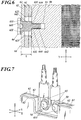
- Fig. 6 is a schematic cross-sectional view of the ink-tank heater 60 attached to the ink tank 50, taken along line VI-VI in Fig. 3 .
- Fig. 7 is an enlarged schematic perspective view of an attachment of thermistors 65 illustrated in Fig. 3 .
- Fig. 8 is a schematic view illustrating essential components of an ink ejecting mechanism 300 including the ink tank 50 and the connections between components of the ink ejecting mechanism 300.
- Fig. 8 omits some of the inkjet heads 241 and second subtanks 52.
- the head unit 24 provided with the ink heating device 80 ejects the ink in the "Z direction," and the "Y direction is orthogonal to the X and Z directions.
- the ink tank 50 stores ink from an ink supplier 70 (see Fig. 8 ) and feeds the stored ink to the inkjet heads 241.
- the ink tank 50 collects and stores the ink remaining in the inkjet heads 241.
- the ink tank 50 is an elongated component extending in the X direction.
- the ink tank 50 is an integrated unit of a first subtank 51 and four second subtanks 52.
- the first subtank 51 and the four second subtanks 52 are disposed along the longitudinal direction of the ink tank 50.
- the first subtank 51 is a depression disposed in the central area of the ink tank 50 extending in the longitudinal direction.
- the first subtank 51 stores the ink from the ink supplier 70 and collects and stores the ink from the inkjet heads 241.
- the first subtank 51 has a meandering flow channel 511 through which the supplied ink flows in the directions indicated by the solid arrows in Fig. 5 .
- One end of the flow channel 511 has an intake portion 512 that receives the ink from the ink supplier 70 or the inkjet heads 241 in the direction indicated by the dotted arrow in Fig. 5 .
- a storage portion 513 is disposed on the other end of the flow channel 511 to store the ink passing through the flow channel 511 and supply the stored ink to the second subtanks.
- the ink from the intake portion 512 flows through the flow channel 511 in a meandering pattern indicated by the arrows in Fig. 5 and is stored in the storage portion 513.
- the ink in the storage portion 513 is fed to the second subtanks 52 with pumps P1 (see Fig. 8 ).
- Two second subtanks 52 which store the ink from the first subtank, are depressions disposed at each longitudinal end of the ink tank 50, as illustrated in Figs. 3 to 5 .
- the ink stored in the second subtanks 52 is fed to two of the eight inkjet modules 242 of the head unit 24. This allows maintenance of the eight inkjet modules 242 of the head unit 24 in units of two.
- the number of second subtanks 52 may be any appropriate number other than four depending on the number of inkjet modules 242 of the head unit 24.
- the ink-tank heater 60 is attached to the ink tank 50 so as to entirely cover one side of the ink tank 50, as illustrated in Figs. 3 and 4 .
- the ink-tank heater 60 includes planer heating members (heaters) 61 disposed on the outer face of the ink tank 50; elastic members 62 disposed on the respective planer heating members 61 on the faces opposite to the ink tank 50; metal plates (flat members) 63 disposed on the respective elastic members 62 on the faces opposite to the planer heating members 61; fixing screws (pressure fixing members) 64 that press the respective metal plates 63 toward the ink tank and fix the respective metal plates 63; thermistors 65 in contact with the ink tank 50; and the controller 40 that individually controls the heating temperatures of the planer heating members 61.
- the planer heating members 61, the elastic members 62, the metal plates 63, the fixing screws 64, and the thermistors 65 are disposed at three positions, i.e., in the central area and at the both longitudinal ends of the ink tank 50.
- the planer heating members 61 and other components are disposed at the positions each corresponding to the first subtank 51 disposed in the central area of the ink tank 50 and the second subtanks 52 disposed at the both longitudinal ends of the ink tank 50.
- the planer heating members 61 which are in direct contact with the outer face of the ink tank 50, heat the outer face of the ink tank 50 to heat the ink inside the ink tank 50.
- a lubricant such as grease, may be applied between the planer heating members 61 and the ink tank 50. Alternatively, the lubricant may be omitted to prevent an increase in processes for production of the inkjet recording device 1 and repair and replacement of the ink-tank heater 60.
- the temperature of the planer heating members 61 is controlled by the controller 40 in response to the temperature detected by the thermistors 65.
- the planer heating members 61 are heaters, specifically rubber heaters, each composed of a planar thermal insulator and a corrugated heating element strips disposed on the thermal insulator sheet, for example.
- the rubber heaters have increased adhesion to the ink tank 50, which leads to a reduction in production costs.
- Each elastic member 62 is disposed between the corresponding planer heating member 61 and the corresponding metal plate 63, as illustrated in Fig. 6 .
- the elastic member 62 is pressed with the corresponding fixing screw 64 via the metal plate 63 and thus is elastically deformed in the thickness direction (Y direction).
- the restoring force of the elastic member 62 applies a substantially uniform strength to the planer heating member 61 in the plane (XZ plane) to press the planer heating member 61 toward the ink tank 50.
- the elastic member 62 may be composed of any material that elastically deforms in response to pressing by the fixing screw 64 and elastically presses the planer heating member 61. Examples of such a material include rubber, sponge, and other spongy or porous materials.
- the metal plate 63 is in contact with the elastic member 62 and serves as the outer face of the ink-tank heater 60, as illustrated in Fig. 6 .
- the fixing screws 64 pass through the respective metal plates 63 disposed in three positions along the longitudinal direction of the ink tank 50 to fix the respective metal plates 63 to the ink tank 50.
- three fixing screws 64 are provided for the metal plate 63 in the central area of the ink tank 50, and two fixing screws 64 are provided for each of the metal plates 63 at the longitudinal ends of the ink tank 50.
- the number and position of the fixing screws 64 provided for each of the metal plates 63 should not be limited to those illustrated in the drawings. Any number of the fixing screws 64 may be provided at any position to press and fix the metal plates 63 to the ink tank 50.
- Each of the fixing screws 64 includes a head 641, a shaft 642, and a spacer 643 having a diameter smaller than that of the shaft 642 and larger than that of the head 641, the spacer 643 being disposed between the head 641 and the shaft 642 in the axial direction, as illustrated in Fig. 6 .
- the fixing screw 64 is fixed to the ink tank 50 by screwing the shaft 642 into an internal thread 53 provided in the outer wall of the ink tank 50 and through the planer heating member 61, the elastic member 62, and the metal plate 63.
- the shaft 642 of the fixing screw 64 is screwed into the outer wall of the ink tank 50 by a predetermined length, and the end face 644 of the spacer 643 comes into contact with the outer face of the ink tank 50, to prevent further insertion of the shaft 642 into the internal thread 53.
- the planer heating member 61, the elastic member 62, and the metal plate 63 have holes 611, 621, and 631, respectively, for passing the fixing screw 64.
- the diameter of the hole 611 in the planer heating member 61 and the diameter of the hole 621 in the elastic member 62 are sufficiently larger than the diameter of the spacer 643, and the diameter of the hole 631 in the metal plate 63 is substantially identical to the diameter of the spacer 643. This facilitates the insertion of the fixing screw 64 to the planer heating member 61 and the elastic member 62 during attachment of the fixing screw 64.
- the head 641 of the fixing screw 64 comes into contact with the metal plate 63 to certainly press the metal plate 63 toward the ink tank 50, and prevent displacement of the metal plate 63 in the plane (XZ plane).
- the spacer 643 of the fixing screw 64 has an axial length L that is smaller than the sum of the thicknesses of the planer heating member 61, the elastic member 62 before elastic deformation, and the metal plate 63, as illustrated in Fig. 6 .
- screwing of the shaft 642 of the fixing screw 64 into the internal thread 53 via the holes 611, 621, and 631 causes the head 641 and the ink tank 50 to clamp the planer heating member 61, the elastic member 62, and the metal plate 63.
- the metal plate 63 in contact with the head 641 is thereby pressed toward the elastic member 62. This causes elastic deformation of the elastic member 62, and the restoring force of the elastic member 62 presses the planer heating member 61 toward the ink tank 50.
- Adjustment of the axial length L of the spacer 643 can adjust the degree of elastic deformation of the elastic member 62 in the thickness direction, and thus determine appropriate restoring force of the elastic member 62 applied to the planer heating member 61.
- the thermistors 65 are in contact with the ink tank 50, as illustrated in Fig. 7 . Specifically, the edges of the planer heating member 61, the elastic member 62, and the metal plate 63 have cutouts through which the ink tank 50 is exposed.
- the thermistors 65 are fixed to the exposed portion 54 with screws 651. Alternative to fixing the thermistors 65 with the screws 651, the thermistors 65 may be in the form of thin films and be disposed between the ink tank 50 and the planer heating members 61. Two thermistors 65 are provided side by side on the exposed portion 54, one of which is provided as a backup.
- the ink-tank heater 60 also includes a thermostat 66.
- the thermostat 66 operates in response to excessively high temperatures of the planer heating members 61 to terminate feeding of the current to the planer heating members 61.
- the thermostat 66 can effectively prevent damage of the planer heating members 61 due to an excessive temperature rise.
- the planer heating members 61, the elastic members 62, the metal plates 63, the fixing screws 64, and the thermistors 65 are disposed at three positions on a side of the ink tank 50, i.e. , in the central area and at the both longitudinal ends of the ink tank 50.
- the heating temperatures of the planer heating members 61 are independently controlled by the controller 40. Specifically, the controller 40 controls the heating temperatures of the planer heating members 61 at the both longitudinal ends of the ink tank 50 to be higher than the heating temperature of the planer heating member 61 in the central area of the ink tank 50.
- the ink tank 50 is an elongated component, heat radiation from the both longitudinal ends is higher than that in the central area, and thus, the temperatures of the ink accommodated at the ends readily decrease compared to that at the central area.
- the second subtanks 52 that feed ink to the inkjet heads 241 are disposed at the both longitudinal ends of the ink tank 50.
- a decrease in temperature at the longitudinal ends of the ink tank 50 may cause ejection failure due to low-temperature ink fed to the inkjet heads 241.
- the controller 40 controls the temperatures of the planer heating members 61 at the both longitudinal ends of the ink tank 50 to be higher than the temperature of the planer heating member 61 in the central area of the ink tank 50.
- the ink inside the second subtanks 52 is evenly and sufficiently heated, and low-temperature ink is prevented from being fed to the inkjet heads 241. This prevents ejection failure.
- the controller 40 controls the heating temperature of the planer heating members 61 at the both longitudinal ends of the ink tank 50 to be approximately 5°C higher than that of the planer heating member 61 in the central area of the ink tank 50.
- the controller 40 starts the control of the planer heating members 61 and maintains a constant heating temperature in accordance with the volume of the ink to be ejected from the inkjet heads 241.
- the ink ejecting mechanism 300 of the inkjet recording device 1 will now be described with reference to Fig. 8 .
- the ink ejecting mechanism 300 includes the ink supplier 70 that supplies ink; the ink tank 50 that stores the ink from the ink supplier 70; the inkjet heads 241 that eject the ink from the ink tank 50; a pressure controller 305 that applies a negative pressure to the nozzles 2411 of the inkjet heads 241; a channel 304 that connects the ink supplier 70 and the ink tank 50; channels 303 that connect the first subtank 51 and the second subtanks 52 in the ink tank 50; supply channels 301 that connect the second subtanks 52 and the inkjet heads 241; collecting channels 302 that connect the inkjet heads 241 and the first subtank 51; and an air channel 306 that connects the second subtanks 52 and the pressure controller 305.
- the ink channels are indicated by dashed lines in Fig. 8 .
- the channels constitute a closed channel through which ink flows.
- the ink supplier 70 stores the ink fed to the components of the ink ejecting mechanism 300 and feeds the stored ink to the first subtank 51 of the ink tank 50.
- the first subtank 51 stores the ink from the ink supplier 70 and feeds the stored ink to the second subtanks 52.
- the ink to be supplied to the first subtank 51 is taken in through the intake portion 512, stored in the storage portion 513 via the flow channel 511, and fed from the storage portion 513 to the second subtanks 52.
- the unheated ink at room-temperature is fed from the ink supplier 70 to the first subtank 51.
- the ink is then fed to the second subtanks 52 via the flow channel 511 in a certain time.
- the ink-tank heater 60 disposed on the exterior of the first subtank 51 sufficiently heats the ink at room-temperature in the first subtank 51. This prevents feeding of ink at a low-temperature even when a large volume ink is to be ejected from the first subtank 51 to the second subtanks 52.
- the second subtanks 52 store the ink from the first subtank 51, and the stored ink is fed to the inkjet heads 241.
- the ink-tank heater 60 is disposed on the exterior of the second subtanks 52 and controlled by the controller 40 so that the temperatures of the planer heating members 61 at the both longitudinal ends of the ink tank 50 are higher than the temperature of the planer heating member 61 in the central area of the ink tank 50. This sufficiently heats the ink stored in the second subtanks 51 and prevents ejection failure due to feeding of the ink at low-temperature to the inkjet heads 241.
- the pressure controllers 305 are connected to the respective second subtanks 52 and control the pressure in the second subtanks 52 under the control of the controller 40. In this way, the pressure controllers 305 apply a negative pressure to the nozzles 2411 of the inkjet heads 241 via the second subtanks 52 and the supply channels 301. This prevents leakage of ink from the nozzles during an intermission of image formation or various maintenance procedures.
- the supply channels 301, the collecting channels 302, and the channels 303 and 304 are tubes through which ink pass. They are composed of a resin or a material having high heat-conductivity.
- the channel 304 connects the first subtank 51 to the ink supplier 70 and is provided with a pump P2.
- the pump P2 operates under the control of the controller 40 and feeds the ink from the ink supplier 70 to the first subtank 51.
- the pump P2 is a positive-displacement pump, such as a diaphragm pump, or a tube pump, for example.
- the channels 303 connect the second subtanks 52 to the first subtank 51 and are provided with the pumps P1.
- the pumps P1 operate under the control of the controller 40 and feed the ink from the first subtank 51 to the second subtanks 52.
- the pumps P1 are positive-displacement pumps, such as diaphragm pumps, or tube pumps, for example.
- the supply channels 301 connect inlets 2412 of the inkjet heads 241 to the second subtanks 52.
- the collecting channels 302 connect outlets 2413 of the inkjet heads 241 to the first subtank 51.
- the air channel 306 connects the second subtanks 52 to the pressure controller 305.
- the air channel 306 is a tube composed of resin, for example, through which air passes.
- the air channel 306 includes a common subchannel 3061 connected to the pressure controller 305 and subchannels 3062 branching from the common subchannel 3061 to connect to the second subtanks 52.
- the collecting channels 302, the channels 303, and the subchannels 3062 are provided with electromagnetic valves 307, 308, and 309, respectively.
- the electromagnetic valves 307, 308, and 309 open and close the relevant ink channels and air channels under the control of the controller 40.
- the electromagnetic valves 307 provided in the collecting channels 302 open and close the collecting channels 302.
- the electromagnetic valves 309 provided in the subchannels 3062 switch connection and disconnection between the second subtanks 52 and the pressure controller 305.
- the second subtanks 52 are containers hermetically sealed except for the various connections described above. That is, the pressure inside the second subtanks 52 varies depending on the negative pressure applied from the pressure controller 305 and/or the ink from the first subtank 51. For example, feeding ink from the first subtank 51 to the second subtanks without application of a negative pressure from the pressure controller 305 during the closed state of the electromagnetic valves 309 causes an increase in pressure in the second subtanks 52 due to an increase in the volume of ink inside the second subtanks 52.
- the first subtank 51 is a container open to the exterior and thus maintains an atmospheric pressure during a variation in the volume of ink.
- the ink-tank heater 60 includes the planer heating members 61 disposed on the external face of the ink tank 50; the elastic members 62 disposed on the faces of the respective planer heating members 61 opposite to the ink tank 50; the metal plates 63 disposed on the faces of the respective elastic members 62 opposite to the planer heating members 61; and the fixing screws 64 that press the respective metal plates 63 toward the ink tank 50 to fix the respective metal plates 63.
- the metal plates 63 are pressed toward the ink tank 50 with the respective fixing screw 64 and cause elastic deformation of the respective elastic members 62.
- the restoring force of the elastic members 62 uniformly presses the respective planer heating members 61. This brings the planer heating members 61 into tight contact with the ink tank 50, allows appropriate temperature control of the ink tank 50 with the planer heating members 61, and achieves efficient heating of the ink tank 50.
- planer heating members 61 The tight contact of the planer heating members 61 to the ink tank 50 prevents formation of a gap or air layer therebetween. This prevents an excess increase in the temperature of the planer heating members 61 and damage to the planer heating members 61.
- the planer heating members 61, the elastic members 62, the metal plates 63, and the fixing screws 64 are disposed at three positions on the ink tank 50, i.e. , in the central area and at the longitudinal ends.
- the heating temperatures of the planer heating members 61 can be controlled to provide a temperature gradient in the longitudinal direction of the ink tank 50, as required.
- the controller 40 independently controlling the heating temperatures of the planer heating members 61 can maintain an appropriate temperature of the ink inside the ink tank 50.
- the planer heating members 61 which are rubber heaters, can reduce production costs and have increased adhesion to the ink tank 50.
- the ink heating device 80 includes the ink tank 50, which is an integrated unit of the first subtank 51 and the second subtanks 52 disposed along the longitudinal direction, and the planer heating members 61, which heats the ink tank 50.
- the planer heating members 61 heats the both longitudinal ends of the ink tank 50 to a temperature higher than the temperature of the central area of the ink tank 50.
- the longitudinal ends of the ink tank 50 which have high heat radiation, can be heated to high temperatures. This reduces uneven heating of the ink distributed across the longitudinal direction of the ink tank 50.
- the ink tank 50 includes the first subtank 51, which is disposed in the central area, and the second subtanks 52, which are disposed at the longitudinal ends and feed ink to the inkjet heads 241.
- the planer heating members 61 heat the second subtanks 52 to a temperature higher than that of the first subtank 51.
- the ink can be maintained at a high temperature immediately before being fed to the inkjet heads 241. This prevents ejection failure of ink due to feeding of ink at a low temperature to the inkjet heads 241.
- the first subtank 51 has the meandering flow channel 511 through which ink flows and the storage portion 513, which stores the ink passing through the flow channel 511 and feeds the stored ink to the second subtanks 52.
- the ink fed to the first subtank 51 can be sufficiently heated by the planer heating members 61. This can prevent feeding of ink at a low temperature to the second subtanks 52 even when large volumes of the ink are ejected. This certainly prevents ejection failure of ink.
- planer heating members 61 are disposed on the outer face of the ink tank 50 at three positions, i.e. , the central area and the both longitudinal ends.
- one planer heating member 61 may cover the entire longitudinal length of a side of the ink tank 50 or two planer heating members 61 may cover the entire longitudinal length of a side of the ink tank 50, for example.
- planer heating members 61 may cover the entire longitudinal length of a side of the ink tank 50.
- the controller 40 controls the temperatures of the planer heating members 61 at the both longitudinal ends of the ink tank 50 to be higher than that of the planer heating member 61 in the central area of the ink tank 50, as described above.
- the controller 40 independently controls the heating temperatures of the three planer heating members 61.
- the temperatures may be controlled in any other way.
- the three planer heating members 61 may be an integrated unit having a low wiring density of the heating element strips of the planer heating member 61 in the central area of the ink tank 50 and a high wiring density at the both longitudinal ends of the ink tank 50. This increases the heating temperatures at the both longitudinal ends to be higher than that of the central area of the ink tank 50.
- the ink-tank heater 60 includes three planer heating members 61, three elastic members 62, and three metal plates 63, disposed on the ink tank 50 along the longitudinal direction.
- these components may be provided in any number.
- three planer heating members 61 may be entirely covered with one elastic member 62 and one metal plate 63, or three planer heating members 61 may be entirely covered with two or more elastic members 62 and two or more metal plates 63.
- the flat members are metal plates 63.
- the flat members may be composed of any material other than metal that has rigidity sufficient for transmitting the pressing force of the fixing screws 64 to the elastic members 62.
- the flat members may be composed of resin.
- the pressure fixing members are fixing screws 64.
- the pressure fixing members may be any component that can fix the metal plates 63 being pressed toward the ink tank 50.
- the pressure fixing members may be snap locks.
- the ink-tank heater 60 includes the thermistors 65.
- any other temperature detectors may be used that can be attached to the ink tank 50 or the planer heating members 61.
- the detectors may include thermocouples that are disposed between the external wall of the ink tank 50 and the planer heating members 61.
- the ink-tank heater 60 may be free from detectors, such as the thermistors 65.
- the planer heating members 61 are disposed on the outer face of the ink.
- the planer heating members 61 may be disposed inside the ink tank 50 or without contact with the ink tank 50.
- the planer heating members 61 without contact with the ink tank 50 may include heaters that are non-planar or heat sources that radiate infrared rays.
- the present invention can be applied to ink heating devices and inkjet recording devices.
Landscapes
- Engineering & Computer Science (AREA)
- Quality & Reliability (AREA)
- Ink Jet (AREA)
Abstract
Description
- The present invention relates to an ink heating device and an inkjet recording device.
- A known inkjet recording device includes inkjet heads that eject ink from nozzles onto a recording medium, to form an image on the recording medium.
- Some of the ink used in the inkjet recording device has viscosity variable by heat. Smooth transfer of the ink from an ink tank to the inkjet heads and stable ejection of the ink from the inkjet heads are achieved through heating of the ink to appropriate temperatures before ejection.
- A technique has been proposed for heating ink in an ink tank to appropriate temperatures with a heater disposed on the outer face of the ink tank feeding ink to inkjet heads (refer to
Patent Document 1, for example). - Patent Document 1: Japanese Unexamined Patent Application Publication No.
2009-285907 - Unfortunately, the heater in the traditional technique described above is disposed only on one of the longitudinal ends of the ink tank. Such a heater causes uneven heating of the ink distributed across the longitudinal direction of the ink tank. Thus, low-temperature ink is supplied to the inkjet heads and causes defects, such as ejection failure.
- An object of the present invention is to provide an ink heating device that reduces unevenness in the temperature of ink in an ink tank in the longitudinal direction of the ink tank, and an inkjet recording device including the ink heating device.
- In order to achieve the object, the invention stated in
claim 1 is an ink heating device that is disposed on an inkjet recording device and heats ink, including: an ink tank that is an integrated unit of subtanks storing ink disposed along longitudinal direction; and at least one heater that heats the ink tank, wherein the at least one heater heats both longitudinal ends of the ink tank to a temperature higher than a temperature of a central area in the longitudinal direction of the ink tank. - The invention stated in claim 2 is the ink heating device according to
claim 1, wherein, the at least one heater includes three heaters disposed in the central area and the both longitudinal ends of the ink tank, and the ink heating device further includes: a controller that independently controls heating temperatures of the heaters. - The invention stated in claim 3 is the ink heating device according to
claim 1 or 2, wherein, the ink tank includes : a first subtank that is disposed in the central area; and second subtanks that are disposed in the both longitudinal ends and feed ink to an inkjet head of the inkjet recording device, and the at least one heater heat the second subtanks to temperatures higher than a temperature of the first subtank. - The invention stated in claim 4 is the ink heating device according to claim 3, wherein the first subtank includes a meandering flow channel through which ink flows and a storage portion that stores the ink from the flow channel and feeds the ink to the second subtanks.
- The invention stated in claim 5 is the ink heating device according to one of
claims 1 to 4, wherein the at least one heater is disposed on the external face of the ink tank. - The invention stated in claim 6 is the ink heating device according to claim 5, wherein, the at least one heater is a planer heating member, and the ink heating device further includes: an elastic member that is disposed on a face of the planer heating member opposite to the ink tank; a flat member that is disposed on a face of the elastic member opposite to the planer heating member; and a pressure fixing member that presses the flat member toward the ink tank.
- The invention stated in claim 7 is an inkjet recording device including: the ink heating device according to one of
claims 1 to 6; and an inkjet head that ejects ink heated by the ink heating device onto a recording medium. - According to the present invention, it is possible to provide an ink heating device that reduces unevenness in the temperature of ink in an ink tank in the longitudinal direction of the ink tank, and an inkjet recording device including the ink heating device.
-
-
Fig. 1 illustrates the essential components of an inkjet recording device according to an embodiment of the present invention. -
Fig. 2A is a schematic side view of an exemplary internal configuration of the head unit. -
Fig. 2B is a schematic view of an exemplary internal configuration of the head unit viewed from a recording medium side. -
Fig. 3 is a schematic perspective view of an ink heating device. -
Fig. 4 is a schematic perspective view of the ink heating device. -
Fig. 5 is a schematic plane view of an ink tank. -
Fig. 6 is a schematic cross-sectional view of an attachment to attach an ink-tank heater to the ink tank taken along line VI-VI inFig. 3 showing. -
Fig. 7 is a schematic perspective view of an attachment to attach thermistors to the ink tank. -
Fig. 8 is a schematic view of essential components of an ink ejecting mechanism and connections between the components of the ink ejecting mechanism. - An inkjet recording device and an ink-tank heater according to embodiments of the present invention will now be described in detail with reference to the drawings. The scope of the invention should not be limited by the drawings. In the description below, components having the same functions or configurations are indicated by the same reference signs, and descriptions thereof are not repeated.
-
Fig. 1 illustrates the essential components of aninkjet recording device 1 according to an embodiment of the present invention. - The
inkjet recording device 1 according to the present invention includes asheet feeder 10, animage forming unit 20, asheet receiver 30, and acontroller 40. In theinkjet recording device 1 controlled by thecontroller 40, theimage forming unit 20 forms an image on a recording medium P conveyed from thesheet feeder 10 to theimage forming unit 20, and then the recording medium P is ejected into thesheet receiver 30. - The
sheet feeder 10 stores the recording media P on which images are to be formed and sends the recording media P to theimage forming unit 20 for image formation. Thesheet feeder 10 includes asheet tray 11 and aconveyer 12. - The
sheet tray 11 is a plate that can hold one or more recording media P. The sheet tray 11 shifts vertically in accordance with the volume of the recording media P placed on thesheet tray 11. The uppermost recording medium P is maintained at a position conveyable by theconveyer 12. - The
conveyer 12 includes a conveying mechanism that circulates an annular belt 123 with multiple (two, for example) rollers 121 and 122 to convey the recording medium P disposed on the belt 123. Theconveyer 12 also includes a supplier that transports the uppermost recording medium P placed on thesheet tray 11 to the belt 123. Theconveyer 12 conveys the recording medium P transported from the supplier onto the belt 123 with the circulation of the belt 123. - The
image forming unit 20 ejects ink onto the recording medium P to form an image. Theimage forming unit 20 includes an image-formingdrum 21, atransporting unit 22, asheet heater 23,head units 24, anirradiator 25, and adelivery unit 26. - The image-forming
drum 21 carries the recording medium P on the cylindrical outer circumferential face and rotates to convey the recording medium P. The conveying face of the image-formingdrum 21 faces thesheet heater 23, thehead units 24, and theirradiator 25, which carry out processes for image formation on the conveyed recording medium P. - The
transporting unit 22 is disposed between theconveyer 12 in thesheet feeder 10 and the image-formingdrum 21 and transports the recording medium P from theconveyer 12 to the image-formingdrum 21. The transportingunit 22 includes aswinging arm 221 that holds one edge of the recording medium P from theconveyer 12 and acylindrical transporting drum 222 that transports the recording medium P held by theswinging arm 221 to the image-formingdrum 21. The recording medium P on theconveyer 12 is lifted by theswinging arm 221 and passed to the transportingdrum 222, to align the recording medium P with the outer circumferential face of the image-formingdrum 21 and transport the recording medium P to the image-formingdrum 21. - The
sheet heater 23 heats the recording medium P carried on the image-formingdrum 21. Thesheet heater 23 includes an infrared heater, for example, and generates heat in response to an input current. Thesheet heater 23 is disposed near the outer circumferential face of the image-formingdrum 21 and upstream of thehead units 24 in the conveying direction of the recording medium P conveyed with the rotating image-formingdrum 21. The heating of thesheet heater 23 is controlled by thecontroller 40 so that the recording medium P carried on the image-formingdrum 21 and passing near thesheet heater 23 reaches a predetermined temperature. - The
head units 24 eject ink onto the recording medium P carried on the image-formingdrum 21, to form an image. Thehead units 24 consist of individual units of the colors cyan (C), magenta (M), yellow (Y), and black (K). With reference toFig. 1 , thehead units 24 corresponding to the colors YMCK are disposed in this order from the upstream of the conveying direction of the recording medium P conveyed with the rotating image-formingdrum 21. - The
head units 24 according to this embodiment are disposed so that they can coat an area having a length (width) larger than that of the entire recording medium P in a direction orthogonal to the conveying direction (width direction) of the recording medium P. In other words, theinkjet recording device 1 is a single-pass inkjet recording device of a line-head type. Each of thehead units 24 can be a line head consisting of aligned inkjet heads 241 (seeFig. 2 ). -
Figs. 2A and 2B illustrate the internal configuration of eachhead unit 24.Fig. 2A is a schematic side view of the internal configuration of one of thehead units 24.Fig. 2B is a schematic view of the internal configuration of thehead unit 24 viewed from the recording medium side. InFig. 2A , thehead units 24 are viewed from a direction orthogonal to the vertical direction of thehead units 24 and orthogonal to the perpendicular direction (the X direction) of the plane ofFig. 1 . - The
head unit 24 includes multiple inkjet heads 241, as illustrated inFigs. 2A and 2B . In the drawings, eachhead unit 24 includes sixteen inkjet heads 241. The sixteen inkjet heads 241 are paired to provide eightinkjet modules 242. - The inkjet heads 241 each have
multiple nozzles 2411. The inkjet heads 241 eject ink from thenozzles 2411 to form an image on the recording medium P carried on the image-formingdrum 21. That is, the inkjet heads 241 are disposed such that thenozzles 2411 are exposed at the lower face of thehead unit 24. Eachinkjet head 241 illustrated inFig. 2B has two arrays of thenozzles 2411 extending in the X direction. - The
inkjet modules 242 are arrayed into two groups extending in the X direction, for example, as illustrated inFig. 2B . The two arrays of theinkjet modules 242 are disposed such that theinkjet modules 242 are arranged in a staggered manner in the direction orthogonal to the X direction. - Each
head unit 24 includes anink heating device 80 that heats the ink to be fed to the inkjet heads 241. Theink heating device 80 will be described in detail below. - The
irradiator 25 emits active energy beams to cure the ink ejected onto the recording medium P in theinkjet recording device 1 according to this embodiment. Theirradiator 25 includes a fluorescent tube, such as a low-pressure mercury lamp, for example, which emits active energy beams such as ultraviolet (UV) rays. Theirradiator 25 is disposed near the outer circumferential face of the image-formingdrum 21 and downstream of thehead units 24 in the conveying direction of the recording medium P conveyed with the rotating image-formingdrum 21. Theirradiator 25 radiates active energy beams onto the recording medium P carried on the image-formingdrum 21 and with the ink ejected and cures the ink on the recording medium P by the active energy beams. - Examples of the fluorescent tube generating UV light other than the low-pressure mercury lamp include a mercury lamp having an operational pressure in the range of several hundred pascals (Pa) to one million pascals (Pa), a light source that functions as a sterilizing lamp, a cold-cathode tube, a UV laser source, a metal halide lamp, and a light-emitting diode. Among such tubes, preferred is a light source that emits high-intensity UV light at low power (for example, light-emitting diode). In addition to UV light, any other active energy beam may be selected for curing the ink depending on the properties of the ink. The light source may also be selected depending on the wavelength of the active energy beam.
- The
delivery unit 26 conveys the recording medium P irradiated with active energy beams from the irradiator 25 from the image-formingdrum 21 to thesheet receiver 30. Thedelivery unit 26 includes a conveying mechanism that circulates anannular belt 263 with rollers (two rollers, for example) 261 and 262 to convey the recording medium P on thebelt 263 and a cylindrical transportingdrum 264 that transports the recording medium P from the image-formingdrum 21 to the conveying mechanism. Thedelivery unit 26 conveys the recording medium P transported onto thebelt 263 from the transportingdrum 264 to thesheet receiver 30 with the circulatingbelt 263. - The
sheet receiver 30 stores the recording media P ejected from theimage forming unit 20 through thedelivery unit 26. Thesheet receiver 30 includes aflat sheet tray 31 on which the recording medium P is placed after image formation. - The
controller 40 comprehensively controls the operation of the components of theinkjet recording device 1. Thecontroller 40 includes a central processing unit (CPU), a read-only memory (ROM), and a random-access memory (RAM). In thecontroller 40, various processing programs, such as a system program stored in the ROM, are read from the ROM and loaded to the RAM. The programs loaded to the RAM are executed by the CPU to carry out various control processes, such as image processing and detection of the failure of liquid feeding described above. - Any ink may be used for the
inkjet recording device 1 according to this embodiment. Examples of such ink include UV curable ink. The UV curable ink exhibits a transition between a gel phase and a liquid (sol) phase depending on the temperature without UV irradiation. The ink has a predetermined phase-transition temperature within the range of approximately 40°C to 100°C, for example. The ink uniformly liquefies (solates) when heated to temperatures higher than the phase-transition temperature. The ink gelates at temperatures lower than the predetermined phase-transition temperature including normal room temperature (0°C to 30°C). - The
ink heating device 80 provided on eachhead unit 24 will now be described with reference toFigs. 3 to 8 . Theink heating device 80 includes anink tank 50, which is an integrated unit of subtanks storing ink and disposed in the longitudinal direction, and an ink-tank heater 60 disposed on the outer face of theink tank 50 heating theink tank 50. -
Figs. 3 and4 are schematic perspective views of theink heating device 80.Fig. 5 is a schematic plane view of theink tank 50.Fig. 6 is a schematic cross-sectional view of the ink-tank heater 60 attached to theink tank 50, taken along line VI-VI inFig. 3 .Fig. 7 is an enlarged schematic perspective view of an attachment ofthermistors 65 illustrated inFig. 3 .Fig. 8 is a schematic view illustrating essential components of anink ejecting mechanism 300 including theink tank 50 and the connections between components of theink ejecting mechanism 300.Fig. 8 omits some of the inkjet heads 241 andsecond subtanks 52. - The
head unit 24 provided with theink heating device 80 ejects the ink in the "Z direction," and the "Y direction is orthogonal to the X and Z directions. - The
ink tank 50 stores ink from an ink supplier 70 (seeFig. 8 ) and feeds the stored ink to the inkjet heads 241. Theink tank 50 collects and stores the ink remaining in the inkjet heads 241. - The
ink tank 50 is an elongated component extending in the X direction. Theink tank 50 is an integrated unit of afirst subtank 51 and foursecond subtanks 52. Thefirst subtank 51 and the foursecond subtanks 52 are disposed along the longitudinal direction of theink tank 50. - With reference to
Figs. 3 to 5 , thefirst subtank 51 is a depression disposed in the central area of theink tank 50 extending in the longitudinal direction. Thefirst subtank 51 stores the ink from theink supplier 70 and collects and stores the ink from the inkjet heads 241. Thefirst subtank 51 has ameandering flow channel 511 through which the supplied ink flows in the directions indicated by the solid arrows inFig. 5 . One end of theflow channel 511 has anintake portion 512 that receives the ink from theink supplier 70 or the inkjet heads 241 in the direction indicated by the dotted arrow inFig. 5 . Astorage portion 513 is disposed on the other end of theflow channel 511 to store the ink passing through theflow channel 511 and supply the stored ink to the second subtanks. In this way, the ink from theintake portion 512 flows through theflow channel 511 in a meandering pattern indicated by the arrows inFig. 5 and is stored in thestorage portion 513. The ink in thestorage portion 513 is fed to thesecond subtanks 52 with pumps P1 (seeFig. 8 ). - Two
second subtanks 52, which store the ink from the first subtank, are depressions disposed at each longitudinal end of theink tank 50, as illustrated inFigs. 3 to 5 . The ink stored in thesecond subtanks 52 is fed to two of the eightinkjet modules 242 of thehead unit 24. This allows maintenance of the eightinkjet modules 242 of thehead unit 24 in units of two. - The number of
second subtanks 52 may be any appropriate number other than four depending on the number ofinkjet modules 242 of thehead unit 24. - The ink-
tank heater 60 is attached to theink tank 50 so as to entirely cover one side of theink tank 50, as illustrated inFigs. 3 and4 . With reference toFig. 6 , the ink-tank heater 60 includes planer heating members (heaters) 61 disposed on the outer face of theink tank 50;elastic members 62 disposed on the respectiveplaner heating members 61 on the faces opposite to theink tank 50; metal plates (flat members) 63 disposed on the respectiveelastic members 62 on the faces opposite to theplaner heating members 61; fixing screws (pressure fixing members) 64 that press therespective metal plates 63 toward the ink tank and fix therespective metal plates 63;thermistors 65 in contact with theink tank 50; and thecontroller 40 that individually controls the heating temperatures of theplaner heating members 61. With reference toFigs. 3 and4 , theplaner heating members 61, theelastic members 62, themetal plates 63, the fixing screws 64, and thethermistors 65 are disposed at three positions, i.e., in the central area and at the both longitudinal ends of theink tank 50. Theplaner heating members 61 and other components are disposed at the positions each corresponding to thefirst subtank 51 disposed in the central area of theink tank 50 and thesecond subtanks 52 disposed at the both longitudinal ends of theink tank 50. - With reference to
Fig. 6 , theplaner heating members 61, which are in direct contact with the outer face of theink tank 50, heat the outer face of theink tank 50 to heat the ink inside theink tank 50. A lubricant, such as grease, may be applied between theplaner heating members 61 and theink tank 50. Alternatively, the lubricant may be omitted to prevent an increase in processes for production of theinkjet recording device 1 and repair and replacement of the ink-tank heater 60. The temperature of theplaner heating members 61 is controlled by thecontroller 40 in response to the temperature detected by thethermistors 65. - The
planer heating members 61 are heaters, specifically rubber heaters, each composed of a planar thermal insulator and a corrugated heating element strips disposed on the thermal insulator sheet, for example. The rubber heaters have increased adhesion to theink tank 50, which leads to a reduction in production costs. - Each
elastic member 62 is disposed between the correspondingplaner heating member 61 and the correspondingmetal plate 63, as illustrated inFig. 6 . Theelastic member 62 is pressed with the corresponding fixingscrew 64 via themetal plate 63 and thus is elastically deformed in the thickness direction (Y direction). The restoring force of theelastic member 62 applies a substantially uniform strength to theplaner heating member 61 in the plane (XZ plane) to press theplaner heating member 61 toward theink tank 50. Theelastic member 62 may be composed of any material that elastically deforms in response to pressing by the fixingscrew 64 and elastically presses theplaner heating member 61. Examples of such a material include rubber, sponge, and other spongy or porous materials. - The
metal plate 63 is in contact with theelastic member 62 and serves as the outer face of the ink-tank heater 60, as illustrated inFig. 6 . - With reference to
Figs. 3 ,4 , and6 , the fixing screws 64 pass through therespective metal plates 63 disposed in three positions along the longitudinal direction of theink tank 50 to fix therespective metal plates 63 to theink tank 50. In the examples illustrated inFigs. 3 and4 , three fixingscrews 64 are provided for themetal plate 63 in the central area of theink tank 50, and two fixingscrews 64 are provided for each of themetal plates 63 at the longitudinal ends of theink tank 50. The number and position of the fixing screws 64 provided for each of themetal plates 63 should not be limited to those illustrated in the drawings. Any number of the fixing screws 64 may be provided at any position to press and fix themetal plates 63 to theink tank 50. - Each of the fixing screws 64 includes a head 641, a
shaft 642, and aspacer 643 having a diameter smaller than that of theshaft 642 and larger than that of the head 641, thespacer 643 being disposed between the head 641 and theshaft 642 in the axial direction, as illustrated inFig. 6 . The fixingscrew 64 is fixed to theink tank 50 by screwing theshaft 642 into aninternal thread 53 provided in the outer wall of theink tank 50 and through theplaner heating member 61, theelastic member 62, and themetal plate 63. Theshaft 642 of the fixingscrew 64 is screwed into the outer wall of theink tank 50 by a predetermined length, and theend face 644 of thespacer 643 comes into contact with the outer face of theink tank 50, to prevent further insertion of theshaft 642 into theinternal thread 53. - With reference to
Fig. 6 , theplaner heating member 61, theelastic member 62, and themetal plate 63 haveholes screw 64. The diameter of thehole 611 in theplaner heating member 61 and the diameter of thehole 621 in theelastic member 62 are sufficiently larger than the diameter of thespacer 643, and the diameter of thehole 631 in themetal plate 63 is substantially identical to the diameter of thespacer 643. This facilitates the insertion of the fixingscrew 64 to theplaner heating member 61 and theelastic member 62 during attachment of the fixingscrew 64. After attachment of the fixingscrew 64, the head 641 of the fixingscrew 64 comes into contact with themetal plate 63 to certainly press themetal plate 63 toward theink tank 50, and prevent displacement of themetal plate 63 in the plane (XZ plane). - The
spacer 643 of the fixingscrew 64 has an axial length L that is smaller than the sum of the thicknesses of theplaner heating member 61, theelastic member 62 before elastic deformation, and themetal plate 63, as illustrated inFig. 6 . Thus, screwing of theshaft 642 of the fixingscrew 64 into theinternal thread 53 via theholes ink tank 50 to clamp theplaner heating member 61, theelastic member 62, and themetal plate 63. Themetal plate 63 in contact with the head 641 is thereby pressed toward theelastic member 62. This causes elastic deformation of theelastic member 62, and the restoring force of theelastic member 62 presses theplaner heating member 61 toward theink tank 50. - Adjustment of the axial length L of the
spacer 643 can adjust the degree of elastic deformation of theelastic member 62 in the thickness direction, and thus determine appropriate restoring force of theelastic member 62 applied to theplaner heating member 61. - The
thermistors 65 are in contact with theink tank 50, as illustrated inFig. 7 . Specifically, the edges of theplaner heating member 61, theelastic member 62, and themetal plate 63 have cutouts through which theink tank 50 is exposed. Thethermistors 65 are fixed to the exposedportion 54 withscrews 651. Alternative to fixing thethermistors 65 with thescrews 651, thethermistors 65 may be in the form of thin films and be disposed between theink tank 50 and theplaner heating members 61. Twothermistors 65 are provided side by side on the exposedportion 54, one of which is provided as a backup. - The ink-
tank heater 60 also includes athermostat 66. Thethermostat 66 operates in response to excessively high temperatures of theplaner heating members 61 to terminate feeding of the current to theplaner heating members 61. Thethermostat 66 can effectively prevent damage of theplaner heating members 61 due to an excessive temperature rise. - As described above, the
planer heating members 61, theelastic members 62, themetal plates 63, the fixing screws 64, and thethermistors 65 are disposed at three positions on a side of theink tank 50, i.e. , in the central area and at the both longitudinal ends of theink tank 50. The heating temperatures of theplaner heating members 61 are independently controlled by thecontroller 40. Specifically, thecontroller 40 controls the heating temperatures of theplaner heating members 61 at the both longitudinal ends of theink tank 50 to be higher than the heating temperature of theplaner heating member 61 in the central area of theink tank 50. - Since the
ink tank 50 is an elongated component, heat radiation from the both longitudinal ends is higher than that in the central area, and thus, the temperatures of the ink accommodated at the ends readily decrease compared to that at the central area. Thesecond subtanks 52 that feed ink to the inkjet heads 241 are disposed at the both longitudinal ends of theink tank 50. Thus, a decrease in temperature at the longitudinal ends of theink tank 50 may cause ejection failure due to low-temperature ink fed to the inkjet heads 241. In this embodiment, thecontroller 40 controls the temperatures of theplaner heating members 61 at the both longitudinal ends of theink tank 50 to be higher than the temperature of theplaner heating member 61 in the central area of theink tank 50. Thus, the ink inside thesecond subtanks 52 is evenly and sufficiently heated, and low-temperature ink is prevented from being fed to the inkjet heads 241. This prevents ejection failure. - In detail, the
controller 40 controls the heating temperature of theplaner heating members 61 at the both longitudinal ends of theink tank 50 to be approximately 5°C higher than that of theplaner heating member 61 in the central area of theink tank 50. Upon turning on the power supply of theinkjet recording device 1, thecontroller 40 starts the control of theplaner heating members 61 and maintains a constant heating temperature in accordance with the volume of the ink to be ejected from the inkjet heads 241. - The
ink ejecting mechanism 300 of theinkjet recording device 1 will now be described with reference toFig. 8 . - The
ink ejecting mechanism 300 includes theink supplier 70 that supplies ink; theink tank 50 that stores the ink from theink supplier 70; the inkjet heads 241 that eject the ink from theink tank 50; apressure controller 305 that applies a negative pressure to thenozzles 2411 of the inkjet heads 241; achannel 304 that connects theink supplier 70 and theink tank 50;channels 303 that connect thefirst subtank 51 and thesecond subtanks 52 in theink tank 50;supply channels 301 that connect thesecond subtanks 52 and the inkjet heads 241; collectingchannels 302 that connect the inkjet heads 241 and thefirst subtank 51; and anair channel 306 that connects thesecond subtanks 52 and thepressure controller 305. - The ink channels are indicated by dashed lines in
Fig. 8 . The channels constitute a closed channel through which ink flows. - The
ink supplier 70 stores the ink fed to the components of theink ejecting mechanism 300 and feeds the stored ink to thefirst subtank 51 of theink tank 50. - The
first subtank 51 stores the ink from theink supplier 70 and feeds the stored ink to thesecond subtanks 52. The ink to be supplied to thefirst subtank 51 is taken in through theintake portion 512, stored in thestorage portion 513 via theflow channel 511, and fed from thestorage portion 513 to thesecond subtanks 52. - The unheated ink at room-temperature is fed from the
ink supplier 70 to thefirst subtank 51. The ink is then fed to thesecond subtanks 52 via theflow channel 511 in a certain time. During this time, the ink-tank heater 60 disposed on the exterior of thefirst subtank 51 sufficiently heats the ink at room-temperature in thefirst subtank 51. This prevents feeding of ink at a low-temperature even when a large volume ink is to be ejected from thefirst subtank 51 to thesecond subtanks 52. - The
second subtanks 52 store the ink from thefirst subtank 51, and the stored ink is fed to the inkjet heads 241. As described above, the ink-tank heater 60 is disposed on the exterior of thesecond subtanks 52 and controlled by thecontroller 40 so that the temperatures of theplaner heating members 61 at the both longitudinal ends of theink tank 50 are higher than the temperature of theplaner heating member 61 in the central area of theink tank 50. This sufficiently heats the ink stored in thesecond subtanks 51 and prevents ejection failure due to feeding of the ink at low-temperature to the inkjet heads 241. - The
pressure controllers 305 are connected to the respectivesecond subtanks 52 and control the pressure in thesecond subtanks 52 under the control of thecontroller 40. In this way, thepressure controllers 305 apply a negative pressure to thenozzles 2411 of the inkjet heads 241 via thesecond subtanks 52 and thesupply channels 301. This prevents leakage of ink from the nozzles during an intermission of image formation or various maintenance procedures. - The
supply channels 301, the collectingchannels 302, and thechannels - The
channel 304 connects thefirst subtank 51 to theink supplier 70 and is provided with a pump P2. The pump P2 operates under the control of thecontroller 40 and feeds the ink from theink supplier 70 to thefirst subtank 51. The pump P2 is a positive-displacement pump, such as a diaphragm pump, or a tube pump, for example. - The
channels 303 connect thesecond subtanks 52 to thefirst subtank 51 and are provided with the pumps P1. The pumps P1 operate under the control of thecontroller 40 and feed the ink from thefirst subtank 51 to thesecond subtanks 52. The pumps P1 are positive-displacement pumps, such as diaphragm pumps, or tube pumps, for example. - The
supply channels 301connect inlets 2412 of the inkjet heads 241 to thesecond subtanks 52. - The collecting
channels 302 connectoutlets 2413 of the inkjet heads 241 to thefirst subtank 51. - The
air channel 306 connects thesecond subtanks 52 to thepressure controller 305. Theair channel 306 is a tube composed of resin, for example, through which air passes. Theair channel 306 includes acommon subchannel 3061 connected to thepressure controller 305 andsubchannels 3062 branching from thecommon subchannel 3061 to connect to thesecond subtanks 52. - The collecting
channels 302, thechannels 303, and thesubchannels 3062 are provided withelectromagnetic valves electromagnetic valves controller 40. Specifically, theelectromagnetic valves 307 provided in the collectingchannels 302 open and close the collectingchannels 302. Theelectromagnetic valves 308, which are provided in thechannels 303 between thefirst subtank 51 and the respective pumps P1, switch connection and disconnection between thefirst subtank 51 and the pumps P1. Theelectromagnetic valves 309 provided in thesubchannels 3062 switch connection and disconnection between thesecond subtanks 52 and thepressure controller 305. - The
second subtanks 52 are containers hermetically sealed except for the various connections described above. That is, the pressure inside thesecond subtanks 52 varies depending on the negative pressure applied from thepressure controller 305 and/or the ink from thefirst subtank 51. For example, feeding ink from thefirst subtank 51 to the second subtanks without application of a negative pressure from thepressure controller 305 during the closed state of theelectromagnetic valves 309 causes an increase in pressure in thesecond subtanks 52 due to an increase in the volume of ink inside thesecond subtanks 52. - In contrast, the
first subtank 51 is a container open to the exterior and thus maintains an atmospheric pressure during a variation in the volume of ink. - The ink-
tank heater 60 according to the embodiment described above includes theplaner heating members 61 disposed on the external face of theink tank 50; theelastic members 62 disposed on the faces of the respectiveplaner heating members 61 opposite to theink tank 50; themetal plates 63 disposed on the faces of the respectiveelastic members 62 opposite to theplaner heating members 61; and the fixing screws 64 that press therespective metal plates 63 toward theink tank 50 to fix therespective metal plates 63. Thus, themetal plates 63 are pressed toward theink tank 50 with the respective fixingscrew 64 and cause elastic deformation of the respectiveelastic members 62. The restoring force of theelastic members 62 uniformly presses the respectiveplaner heating members 61. This brings theplaner heating members 61 into tight contact with theink tank 50, allows appropriate temperature control of theink tank 50 with theplaner heating members 61, and achieves efficient heating of theink tank 50. - The tight contact of the
planer heating members 61 to theink tank 50 prevents formation of a gap or air layer therebetween. This prevents an excess increase in the temperature of theplaner heating members 61 and damage to theplaner heating members 61. - The
planer heating members 61, theelastic members 62, themetal plates 63, and the fixing screws 64 are disposed at three positions on theink tank 50, i.e. , in the central area and at the longitudinal ends. Thus, the heating temperatures of theplaner heating members 61 can be controlled to provide a temperature gradient in the longitudinal direction of theink tank 50, as required. - The
controller 40 independently controlling the heating temperatures of theplaner heating members 61 can maintain an appropriate temperature of the ink inside theink tank 50. - The
planer heating members 61, which are rubber heaters, can reduce production costs and have increased adhesion to theink tank 50. - The
ink heating device 80 includes theink tank 50, which is an integrated unit of thefirst subtank 51 and thesecond subtanks 52 disposed along the longitudinal direction, and theplaner heating members 61, which heats theink tank 50. Theplaner heating members 61 heats the both longitudinal ends of theink tank 50 to a temperature higher than the temperature of the central area of theink tank 50. Thus, the longitudinal ends of theink tank 50, which have high heat radiation, can be heated to high temperatures. This reduces uneven heating of the ink distributed across the longitudinal direction of theink tank 50. - The
ink tank 50 includes thefirst subtank 51, which is disposed in the central area, and thesecond subtanks 52, which are disposed at the longitudinal ends and feed ink to the inkjet heads 241. Theplaner heating members 61 heat thesecond subtanks 52 to a temperature higher than that of thefirst subtank 51. Thus, the ink can be maintained at a high temperature immediately before being fed to the inkjet heads 241. This prevents ejection failure of ink due to feeding of ink at a low temperature to the inkjet heads 241. - The
first subtank 51 has themeandering flow channel 511 through which ink flows and thestorage portion 513, which stores the ink passing through theflow channel 511 and feeds the stored ink to thesecond subtanks 52. Thus, the ink fed to thefirst subtank 51 can be sufficiently heated by theplaner heating members 61. This can prevent feeding of ink at a low temperature to thesecond subtanks 52 even when large volumes of the ink are ejected. This certainly prevents ejection failure of ink. - In the embodiment described above, the
planer heating members 61 are disposed on the outer face of theink tank 50 at three positions, i.e. , the central area and the both longitudinal ends. Alternatively, oneplaner heating member 61 may cover the entire longitudinal length of a side of theink tank 50 or twoplaner heating members 61 may cover the entire longitudinal length of a side of theink tank 50, for example. - Alternatively, four or more
planer heating members 61 may cover the entire longitudinal length of a side of theink tank 50. In such a case, it is preferred that thecontroller 40 controls the temperatures of theplaner heating members 61 at the both longitudinal ends of theink tank 50 to be higher than that of theplaner heating member 61 in the central area of theink tank 50, as described above. - In the embodiments described above, the
controller 40 independently controls the heating temperatures of the threeplaner heating members 61. Alternatively, the temperatures may be controlled in any other way. For example, the threeplaner heating members 61 may be an integrated unit having a low wiring density of the heating element strips of theplaner heating member 61 in the central area of theink tank 50 and a high wiring density at the both longitudinal ends of theink tank 50. This increases the heating temperatures at the both longitudinal ends to be higher than that of the central area of theink tank 50. - In the embodiments described above, the ink-
tank heater 60 includes threeplaner heating members 61, threeelastic members 62, and threemetal plates 63, disposed on theink tank 50 along the longitudinal direction. Alternatively, these components may be provided in any number. For example, threeplaner heating members 61 may be entirely covered with oneelastic member 62 and onemetal plate 63, or threeplaner heating members 61 may be entirely covered with two or moreelastic members 62 and two ormore metal plates 63. - In the embodiments described above, the flat members are
metal plates 63. Alternatively, the flat members may be composed of any material other than metal that has rigidity sufficient for transmitting the pressing force of the fixing screws 64 to theelastic members 62. For example, the flat members may be composed of resin. - In the embodiments described above, the pressure fixing members are fixing
screws 64. Alternatively, the pressure fixing members may be any component that can fix themetal plates 63 being pressed toward theink tank 50. For example, the pressure fixing members may be snap locks. - In the embodiments described above, the ink-
tank heater 60 includes thethermistors 65. Alternatively, any other temperature detectors may be used that can be attached to theink tank 50 or theplaner heating members 61. For example, the detectors may include thermocouples that are disposed between the external wall of theink tank 50 and theplaner heating members 61. The ink-tank heater 60 may be free from detectors, such as thethermistors 65. - In the embodiments described above, the
planer heating members 61 are disposed on the outer face of the ink. Alternatively, theplaner heating members 61 may be disposed inside theink tank 50 or without contact with theink tank 50. Theplaner heating members 61 without contact with theink tank 50 may include heaters that are non-planar or heat sources that radiate infrared rays. - The present invention can be applied to ink heating devices and inkjet recording devices.
-
- 1
- inkjet recording device
- 40
- controller
- 50
- ink tank
- 51
- first subtank
- 52
- second subtank
- 60
- ink-tank heater
- 61
- planer heating member (heater)
- 62
- elastic member
- 63
- metal plate (flat member)
- 64
- fixing screw (pressure fixing member)
- 80
- ink heating device
- 241
- inkjet head
- 511
- flow channel
- 513
- storage portion
Claims (7)
- An ink heating device that is disposed on an inkjet recording device and heats ink, comprising:an ink tank that is an integrated unit of subtanks storing ink disposed along longitudinal direction; andat least one heater that heats the ink tank,wherein the at least one heater heats both longitudinal ends of the ink tank to a temperature higher than a temperature of a central area in the longitudinal direction of the ink tank.
- The ink heating device according to claim 1, wherein,
the at least one heater comprises three heaters disposed in the central area and the both longitudinal ends of the ink tank, and
the ink heating device further comprises:a controller that independently controls heating temperatures of the heaters. - The ink heating device according to claim 1 or 2, wherein, the ink tank comprises:a first subtank that is disposed in the central area; andsecond subtanks that are disposed in the both longitudinal ends and feed ink to an inkjet head of the inkjet recording device, andthe at least one heater heat the second subtanks to temperatures higher than a temperature of the first subtank.
- The ink heating device according to claim 3, wherein the first subtank comprises a meandering flow channel through which ink flows and a storage portion that stores the ink from the flow channel and feeds the ink to the second subtanks.
- The ink heating device according to one of claims 1 to 4, wherein the at least one heater is disposed on the external face of the ink tank.
- The ink heating device according to claim 5, wherein,
the at least one heater is a planer heating member, and
the ink heating device further comprises:an elastic member that is disposed on a face of the planer heating member opposite to the ink tank;a flat member that is disposed on a face of the elastic member opposite to the planer heating member; anda pressure fixing member that presses the flat member toward the ink tank. - An inkjet recording device comprising:the ink heating device according to one of claims 1 to 6; andan inkjet head that ejects ink heated by the ink heating device onto a recording medium.
Applications Claiming Priority (2)
| Application Number | Priority Date | Filing Date | Title |
|---|---|---|---|
| JP2014208472 | 2014-10-10 | ||
| PCT/JP2015/077893 WO2016056450A1 (en) | 2014-10-10 | 2015-10-01 | Ink heating device and inkjet recording device |
Publications (3)
| Publication Number | Publication Date |
|---|---|
| EP3205504A1 true EP3205504A1 (en) | 2017-08-16 |
| EP3205504A4 EP3205504A4 (en) | 2018-05-23 |
| EP3205504B1 EP3205504B1 (en) | 2019-08-21 |
Family
ID=55653065
Family Applications (1)
| Application Number | Title | Priority Date | Filing Date |
|---|---|---|---|
| EP15849350.2A Active EP3205504B1 (en) | 2014-10-10 | 2015-10-01 | Ink heating device and inkjet recording device |
Country Status (5)
| Country | Link |
|---|---|
| US (1) | US9994028B2 (en) |
| EP (1) | EP3205504B1 (en) |
| JP (1) | JP6620753B2 (en) |
| CN (1) | CN107107619B (en) |
| WO (1) | WO2016056450A1 (en) |
Cited By (1)
| Publication number | Priority date | Publication date | Assignee | Title |
|---|---|---|---|---|
| EP3686017A1 (en) * | 2019-01-24 | 2020-07-29 | KYOCERA Document Solutions Inc. | Head unit and inkjet recording apparatus |
Families Citing this family (6)
| Publication number | Priority date | Publication date | Assignee | Title |
|---|---|---|---|---|
| JP6809254B2 (en) * | 2017-01-27 | 2021-01-06 | セイコーエプソン株式会社 | Liquid injection system and computer program |
| JP7422561B2 (en) * | 2020-02-28 | 2024-01-26 | 株式会社Screenホールディングス | printing device |
| CN113232421A (en) * | 2021-04-26 | 2021-08-10 | 北京中电元德科技有限责任公司 | Secondary ink box for ink-jet printer |
| JP7687116B2 (en) * | 2021-07-29 | 2025-06-03 | コニカミノルタ株式会社 | Image forming apparatus and heating control method |
| KR20230133762A (en) | 2022-03-11 | 2023-09-19 | 캐논 가부시끼가이샤 | Liquid discharge apparatus, liquid discharge method, article manufacturing method |
| GB202204762D0 (en) * | 2022-04-01 | 2022-05-18 | Ricoh Co Ltd | Ink delivery system |
Family Cites Families (13)
| Publication number | Priority date | Publication date | Assignee | Title |
|---|---|---|---|---|
| JPH09248918A (en) * | 1996-03-15 | 1997-09-22 | Sharp Corp | Image recording device |
| JPH1148498A (en) * | 1997-07-30 | 1999-02-23 | Tec Corp | Ink jet printer |
| US6312094B1 (en) * | 1997-07-30 | 2001-11-06 | Toshiba Tec Kabushiki Kaisha | Ink-jet printer |
| JP2003341099A (en) * | 2002-05-29 | 2003-12-03 | Konica Minolta Holdings Inc | Inkjet printer |
| US7207641B2 (en) * | 2003-09-05 | 2007-04-24 | Konica Minolta Holdings, Inc. | Inkjet head |
| JP2005081597A (en) * | 2003-09-05 | 2005-03-31 | Konica Minolta Holdings Inc | Inkjet head |
| JP4457254B2 (en) * | 2004-10-25 | 2010-04-28 | コニカミノルタビジネステクノロジーズ株式会社 | Image forming apparatus |
| US20070035594A1 (en) * | 2005-08-10 | 2007-02-15 | Brooks Jeffrey B | Ink supply system |
| JP5007273B2 (en) | 2008-05-28 | 2012-08-22 | 大日本スクリーン製造株式会社 | Ink tank and printing device |
| US8092000B2 (en) * | 2009-01-19 | 2012-01-10 | Xerox Corporation | Heat element configuration for a reservoir heater |
| JP5615575B2 (en) * | 2009-09-11 | 2014-10-29 | 株式会社セイコーアイ・インフォテック | Inkjet printer |
| JP5975039B2 (en) * | 2011-11-21 | 2016-08-23 | コニカミノルタ株式会社 | Ink jet recording apparatus and ink supply method in ink jet recording apparatus |
| JP6011610B2 (en) * | 2012-03-14 | 2016-10-19 | コニカミノルタ株式会社 | Image forming apparatus |
-
2015
- 2015-10-01 JP JP2016553064A patent/JP6620753B2/en active Active
- 2015-10-01 WO PCT/JP2015/077893 patent/WO2016056450A1/en not_active Ceased
- 2015-10-01 US US15/513,860 patent/US9994028B2/en active Active
- 2015-10-01 CN CN201580054469.6A patent/CN107107619B/en active Active
- 2015-10-01 EP EP15849350.2A patent/EP3205504B1/en active Active
Cited By (2)
| Publication number | Priority date | Publication date | Assignee | Title |
|---|---|---|---|---|
| EP3686017A1 (en) * | 2019-01-24 | 2020-07-29 | KYOCERA Document Solutions Inc. | Head unit and inkjet recording apparatus |
| US11148418B2 (en) | 2019-01-24 | 2021-10-19 | Kyocera Document Solutions Inc. | Head unit and inkjet recording apparatus |
Also Published As
| Publication number | Publication date |
|---|---|
| US9994028B2 (en) | 2018-06-12 |
| US20170291422A1 (en) | 2017-10-12 |
| CN107107619B (en) | 2019-06-28 |
| WO2016056450A1 (en) | 2016-04-14 |
| EP3205504B1 (en) | 2019-08-21 |
| JPWO2016056450A1 (en) | 2017-07-20 |
| JP6620753B2 (en) | 2019-12-18 |
| CN107107619A (en) | 2017-08-29 |
| EP3205504A4 (en) | 2018-05-23 |
Similar Documents
| Publication | Publication Date | Title |
|---|---|---|
| EP3205504B1 (en) | Ink heating device and inkjet recording device | |
| US11559997B2 (en) | Heating device, dryer, liquid discharge apparatus, and printer | |
| US9561665B2 (en) | Liquid discharge device | |
| CN115916542B (en) | Printing apparatus and printing method | |
| CN108068454B (en) | Method for operating a UV-curing device of a printing press | |
| US11235570B2 (en) | Liquid discharge apparatus | |
| JP6988105B2 (en) | Inkjet recording device and control method of inkjet recording device | |
| JP6405869B2 (en) | Ink tank heating apparatus and inkjet recording apparatus | |
| JP2017094734A (en) | Method for controlling temperature of sheet in printing machine | |
| JP7687116B2 (en) | Image forming apparatus and heating control method | |
| EP2347980B1 (en) | Air blowing apparatus | |
| US11640128B2 (en) | Liquid discharge head, liquid discharge device, and liquid discharge apparatus | |
| JP2014213454A (en) | Ink jet recorder | |
| JP6822838B2 (en) | Ink temperature control method and ink temperature control method | |
| JP6900711B2 (en) | Inkjet recording device and control method of inkjet recording device | |
| JP7119719B2 (en) | Heaters and inkjet printers | |
| JP2021187678A (en) | Heating device, drying device, liquid ejection device, printing device | |
| US12257852B2 (en) | Ink supply device and image forming apparatus | |
| US11724521B2 (en) | Ink heating device and printing apparatus | |
| JP2020013671A (en) | Heater and inkjet printing machine | |
| US12539700B2 (en) | Head module, image forming apparatus, and liquid discharge apparatus | |
| US9643412B1 (en) | Ejection apparatus | |
| JP2025064251A (en) | Fixing device |
Legal Events
| Date | Code | Title | Description |
|---|---|---|---|
| STAA | Information on the status of an ep patent application or granted ep patent |
Free format text: STATUS: THE INTERNATIONAL PUBLICATION HAS BEEN MADE |
|
| PUAI | Public reference made under article 153(3) epc to a published international application that has entered the european phase |
Free format text: ORIGINAL CODE: 0009012 |
|
| STAA | Information on the status of an ep patent application or granted ep patent |
Free format text: STATUS: REQUEST FOR EXAMINATION WAS MADE |
|
| 17P | Request for examination filed |
Effective date: 20170309 |
|
| AK | Designated contracting states |
Kind code of ref document: A1 Designated state(s): AL AT BE BG CH CY CZ DE DK EE ES FI FR GB GR HR HU IE IS IT LI LT LU LV MC MK MT NL NO PL PT RO RS SE SI SK SM TR |
|
| AX | Request for extension of the european patent |
Extension state: BA ME |
|
| DAV | Request for validation of the european patent (deleted) | ||
| DAX | Request for extension of the european patent (deleted) | ||
| A4 | Supplementary search report drawn up and despatched |
Effective date: 20180424 |
|
| RIC1 | Information provided on ipc code assigned before grant |
Ipc: B41J 2/17 20060101ALI20180418BHEP Ipc: B41J 2/195 20060101ALI20180418BHEP Ipc: B41J 2/175 20060101AFI20180418BHEP Ipc: B41J 2/18 20060101ALI20180418BHEP |
|
| GRAP | Despatch of communication of intention to grant a patent |
Free format text: ORIGINAL CODE: EPIDOSNIGR1 |
|
| STAA | Information on the status of an ep patent application or granted ep patent |
Free format text: STATUS: GRANT OF PATENT IS INTENDED |
|
| INTG | Intention to grant announced |
Effective date: 20190325 |
|
| GRAS | Grant fee paid |
Free format text: ORIGINAL CODE: EPIDOSNIGR3 |
|
| GRAA | (expected) grant |
Free format text: ORIGINAL CODE: 0009210 |
|
| STAA | Information on the status of an ep patent application or granted ep patent |
Free format text: STATUS: THE PATENT HAS BEEN GRANTED |
|
| AK | Designated contracting states |
Kind code of ref document: B1 Designated state(s): AL AT BE BG CH CY CZ DE DK EE ES FI FR GB GR HR HU IE IS IT LI LT LU LV MC MK MT NL NO PL PT RO RS SE SI SK SM TR |
|
| REG | Reference to a national code |
Ref country code: GB Ref legal event code: FG4D |
|
| REG | Reference to a national code |
Ref country code: DE Ref legal event code: R082 Ref document number: 602015036460 Country of ref document: DE Representative=s name: PATENTANWAELTE HENKEL, BREUER & PARTNER MBB, DE Ref country code: DE Ref legal event code: R082 Ref document number: 602015036460 Country of ref document: DE Representative=s name: HENKEL & PARTNER MBB PATENTANWALTSKANZLEI, REC, DE |
|
| REG | Reference to a national code |
Ref country code: CH Ref legal event code: EP |
|
| REG | Reference to a national code |
Ref country code: DE Ref legal event code: R096 Ref document number: 602015036460 Country of ref document: DE |
|
| REG | Reference to a national code |
Ref country code: AT Ref legal event code: REF Ref document number: 1169270 Country of ref document: AT Kind code of ref document: T Effective date: 20190915 |
|
| REG | Reference to a national code |
Ref country code: IE Ref legal event code: FG4D |
|
| REG | Reference to a national code |
Ref country code: LT Ref legal event code: MG4D |
|
| REG | Reference to a national code |
Ref country code: NL Ref legal event code: MP Effective date: 20190821 |
|
| PG25 | Lapsed in a contracting state [announced via postgrant information from national office to epo] |
Ref country code: NO Free format text: LAPSE BECAUSE OF FAILURE TO SUBMIT A TRANSLATION OF THE DESCRIPTION OR TO PAY THE FEE WITHIN THE PRESCRIBED TIME-LIMIT Effective date: 20191121 Ref country code: BG Free format text: LAPSE BECAUSE OF FAILURE TO SUBMIT A TRANSLATION OF THE DESCRIPTION OR TO PAY THE FEE WITHIN THE PRESCRIBED TIME-LIMIT Effective date: 20191121 Ref country code: PT Free format text: LAPSE BECAUSE OF FAILURE TO SUBMIT A TRANSLATION OF THE DESCRIPTION OR TO PAY THE FEE WITHIN THE PRESCRIBED TIME-LIMIT Effective date: 20191223 Ref country code: HR Free format text: LAPSE BECAUSE OF FAILURE TO SUBMIT A TRANSLATION OF THE DESCRIPTION OR TO PAY THE FEE WITHIN THE PRESCRIBED TIME-LIMIT Effective date: 20190821 Ref country code: SE Free format text: LAPSE BECAUSE OF FAILURE TO SUBMIT A TRANSLATION OF THE DESCRIPTION OR TO PAY THE FEE WITHIN THE PRESCRIBED TIME-LIMIT Effective date: 20190821 Ref country code: FI Free format text: LAPSE BECAUSE OF FAILURE TO SUBMIT A TRANSLATION OF THE DESCRIPTION OR TO PAY THE FEE WITHIN THE PRESCRIBED TIME-LIMIT Effective date: 20190821 Ref country code: LT Free format text: LAPSE BECAUSE OF FAILURE TO SUBMIT A TRANSLATION OF THE DESCRIPTION OR TO PAY THE FEE WITHIN THE PRESCRIBED TIME-LIMIT Effective date: 20190821 Ref country code: NL Free format text: LAPSE BECAUSE OF FAILURE TO SUBMIT A TRANSLATION OF THE DESCRIPTION OR TO PAY THE FEE WITHIN THE PRESCRIBED TIME-LIMIT Effective date: 20190821 |
|
| PG25 | Lapsed in a contracting state [announced via postgrant information from national office to epo] |
Ref country code: GR Free format text: LAPSE BECAUSE OF FAILURE TO SUBMIT A TRANSLATION OF THE DESCRIPTION OR TO PAY THE FEE WITHIN THE PRESCRIBED TIME-LIMIT Effective date: 20191122 Ref country code: ES Free format text: LAPSE BECAUSE OF FAILURE TO SUBMIT A TRANSLATION OF THE DESCRIPTION OR TO PAY THE FEE WITHIN THE PRESCRIBED TIME-LIMIT Effective date: 20190821 Ref country code: LV Free format text: LAPSE BECAUSE OF FAILURE TO SUBMIT A TRANSLATION OF THE DESCRIPTION OR TO PAY THE FEE WITHIN THE PRESCRIBED TIME-LIMIT Effective date: 20190821 Ref country code: AL Free format text: LAPSE BECAUSE OF FAILURE TO SUBMIT A TRANSLATION OF THE DESCRIPTION OR TO PAY THE FEE WITHIN THE PRESCRIBED TIME-LIMIT Effective date: 20190821 Ref country code: IS Free format text: LAPSE BECAUSE OF FAILURE TO SUBMIT A TRANSLATION OF THE DESCRIPTION OR TO PAY THE FEE WITHIN THE PRESCRIBED TIME-LIMIT Effective date: 20191221 Ref country code: RS Free format text: LAPSE BECAUSE OF FAILURE TO SUBMIT A TRANSLATION OF THE DESCRIPTION OR TO PAY THE FEE WITHIN THE PRESCRIBED TIME-LIMIT Effective date: 20190821 |
|
| REG | Reference to a national code |
Ref country code: AT Ref legal event code: MK05 Ref document number: 1169270 Country of ref document: AT Kind code of ref document: T Effective date: 20190821 |
|
| PG25 | Lapsed in a contracting state [announced via postgrant information from national office to epo] |
Ref country code: TR Free format text: LAPSE BECAUSE OF FAILURE TO SUBMIT A TRANSLATION OF THE DESCRIPTION OR TO PAY THE FEE WITHIN THE PRESCRIBED TIME-LIMIT Effective date: 20190821 |
|
| PG25 | Lapsed in a contracting state [announced via postgrant information from national office to epo] |
Ref country code: RO Free format text: LAPSE BECAUSE OF FAILURE TO SUBMIT A TRANSLATION OF THE DESCRIPTION OR TO PAY THE FEE WITHIN THE PRESCRIBED TIME-LIMIT Effective date: 20190821 Ref country code: PL Free format text: LAPSE BECAUSE OF FAILURE TO SUBMIT A TRANSLATION OF THE DESCRIPTION OR TO PAY THE FEE WITHIN THE PRESCRIBED TIME-LIMIT Effective date: 20190821 Ref country code: EE Free format text: LAPSE BECAUSE OF FAILURE TO SUBMIT A TRANSLATION OF THE DESCRIPTION OR TO PAY THE FEE WITHIN THE PRESCRIBED TIME-LIMIT Effective date: 20190821 Ref country code: AT Free format text: LAPSE BECAUSE OF FAILURE TO SUBMIT A TRANSLATION OF THE DESCRIPTION OR TO PAY THE FEE WITHIN THE PRESCRIBED TIME-LIMIT Effective date: 20190821 Ref country code: IT Free format text: LAPSE BECAUSE OF FAILURE TO SUBMIT A TRANSLATION OF THE DESCRIPTION OR TO PAY THE FEE WITHIN THE PRESCRIBED TIME-LIMIT Effective date: 20190821 Ref country code: DK Free format text: LAPSE BECAUSE OF FAILURE TO SUBMIT A TRANSLATION OF THE DESCRIPTION OR TO PAY THE FEE WITHIN THE PRESCRIBED TIME-LIMIT Effective date: 20190821 |
|
| PG25 | Lapsed in a contracting state [announced via postgrant information from national office to epo] |
Ref country code: IS Free format text: LAPSE BECAUSE OF FAILURE TO SUBMIT A TRANSLATION OF THE DESCRIPTION OR TO PAY THE FEE WITHIN THE PRESCRIBED TIME-LIMIT Effective date: 20200224 Ref country code: MC Free format text: LAPSE BECAUSE OF FAILURE TO SUBMIT A TRANSLATION OF THE DESCRIPTION OR TO PAY THE FEE WITHIN THE PRESCRIBED TIME-LIMIT Effective date: 20190821 Ref country code: SM Free format text: LAPSE BECAUSE OF FAILURE TO SUBMIT A TRANSLATION OF THE DESCRIPTION OR TO PAY THE FEE WITHIN THE PRESCRIBED TIME-LIMIT Effective date: 20190821 Ref country code: SK Free format text: LAPSE BECAUSE OF FAILURE TO SUBMIT A TRANSLATION OF THE DESCRIPTION OR TO PAY THE FEE WITHIN THE PRESCRIBED TIME-LIMIT Effective date: 20190821 Ref country code: CZ Free format text: LAPSE BECAUSE OF FAILURE TO SUBMIT A TRANSLATION OF THE DESCRIPTION OR TO PAY THE FEE WITHIN THE PRESCRIBED TIME-LIMIT Effective date: 20190821 |
|
| REG | Reference to a national code |
Ref country code: CH Ref legal event code: PL |
|
| REG | Reference to a national code |
Ref country code: DE Ref legal event code: R097 Ref document number: 602015036460 Country of ref document: DE |
|
| PLBE | No opposition filed within time limit |
Free format text: ORIGINAL CODE: 0009261 |
|
| STAA | Information on the status of an ep patent application or granted ep patent |
Free format text: STATUS: NO OPPOSITION FILED WITHIN TIME LIMIT |
|
| PG2D | Information on lapse in contracting state deleted |
Ref country code: IS |
|
| PG25 | Lapsed in a contracting state [announced via postgrant information from national office to epo] |
Ref country code: LU Free format text: LAPSE BECAUSE OF NON-PAYMENT OF DUE FEES Effective date: 20191001 Ref country code: CH Free format text: LAPSE BECAUSE OF NON-PAYMENT OF DUE FEES Effective date: 20191031 Ref country code: LI Free format text: LAPSE BECAUSE OF NON-PAYMENT OF DUE FEES Effective date: 20191031 |
|
| 26N | No opposition filed |
Effective date: 20200603 |
|
| REG | Reference to a national code |
Ref country code: BE Ref legal event code: MM Effective date: 20191031 |
|
| PG25 | Lapsed in a contracting state [announced via postgrant information from national office to epo] |
Ref country code: BE Free format text: LAPSE BECAUSE OF NON-PAYMENT OF DUE FEES Effective date: 20191031 Ref country code: SI Free format text: LAPSE BECAUSE OF FAILURE TO SUBMIT A TRANSLATION OF THE DESCRIPTION OR TO PAY THE FEE WITHIN THE PRESCRIBED TIME-LIMIT Effective date: 20190821 |
|
| PG25 | Lapsed in a contracting state [announced via postgrant information from national office to epo] |
Ref country code: IE Free format text: LAPSE BECAUSE OF NON-PAYMENT OF DUE FEES Effective date: 20191001 |
|
| PG25 | Lapsed in a contracting state [announced via postgrant information from national office to epo] |
Ref country code: CY Free format text: LAPSE BECAUSE OF FAILURE TO SUBMIT A TRANSLATION OF THE DESCRIPTION OR TO PAY THE FEE WITHIN THE PRESCRIBED TIME-LIMIT Effective date: 20190821 |
|
| PG25 | Lapsed in a contracting state [announced via postgrant information from national office to epo] |
Ref country code: HU Free format text: LAPSE BECAUSE OF FAILURE TO SUBMIT A TRANSLATION OF THE DESCRIPTION OR TO PAY THE FEE WITHIN THE PRESCRIBED TIME-LIMIT; INVALID AB INITIO Effective date: 20151001 Ref country code: MT Free format text: LAPSE BECAUSE OF FAILURE TO SUBMIT A TRANSLATION OF THE DESCRIPTION OR TO PAY THE FEE WITHIN THE PRESCRIBED TIME-LIMIT Effective date: 20190821 |
|
| PG25 | Lapsed in a contracting state [announced via postgrant information from national office to epo] |
Ref country code: MK Free format text: LAPSE BECAUSE OF FAILURE TO SUBMIT A TRANSLATION OF THE DESCRIPTION OR TO PAY THE FEE WITHIN THE PRESCRIBED TIME-LIMIT Effective date: 20190821 |
|
| P01 | Opt-out of the competence of the unified patent court (upc) registered |
Effective date: 20230510 |
|
| PGFP | Annual fee paid to national office [announced via postgrant information from national office to epo] |
Ref country code: GB Payment date: 20250904 Year of fee payment: 11 |
|
| PGFP | Annual fee paid to national office [announced via postgrant information from national office to epo] |
Ref country code: FR Payment date: 20250908 Year of fee payment: 11 |
|
| PGFP | Annual fee paid to national office [announced via postgrant information from national office to epo] |
Ref country code: DE Payment date: 20250902 Year of fee payment: 11 |