EP3205437B1 - Elektrisches verbindungsverfahren und elektrische verbindungsvorrichtung - Google Patents
Elektrisches verbindungsverfahren und elektrische verbindungsvorrichtung Download PDFInfo
- Publication number
- EP3205437B1 EP3205437B1 EP15849434.4A EP15849434A EP3205437B1 EP 3205437 B1 EP3205437 B1 EP 3205437B1 EP 15849434 A EP15849434 A EP 15849434A EP 3205437 B1 EP3205437 B1 EP 3205437B1
- Authority
- EP
- European Patent Office
- Prior art keywords
- bonding
- bonding target
- target member
- face
- displacement amount
- Prior art date
- Legal status (The legal status is an assumption and is not a legal conclusion. Google has not performed a legal analysis and makes no representation as to the accuracy of the status listed.)
- Not-in-force
Links
Images


Classifications
-
- B—PERFORMING OPERATIONS; TRANSPORTING
- B23—MACHINE TOOLS; METAL-WORKING NOT OTHERWISE PROVIDED FOR
- B23K—SOLDERING OR UNSOLDERING; WELDING; CLADDING OR PLATING BY SOLDERING OR WELDING; CUTTING BY APPLYING HEAT LOCALLY, e.g. FLAME CUTTING; WORKING BY LASER BEAM
- B23K11/00—Resistance welding; Severing by resistance heating
- B23K11/002—Resistance welding; Severing by resistance heating specially adapted for particular articles or work
-
- B—PERFORMING OPERATIONS; TRANSPORTING
- B23—MACHINE TOOLS; METAL-WORKING NOT OTHERWISE PROVIDED FOR
- B23K—SOLDERING OR UNSOLDERING; WELDING; CLADDING OR PLATING BY SOLDERING OR WELDING; CUTTING BY APPLYING HEAT LOCALLY, e.g. FLAME CUTTING; WORKING BY LASER BEAM
- B23K11/00—Resistance welding; Severing by resistance heating
- B23K11/02—Pressure butt welding
-
- B—PERFORMING OPERATIONS; TRANSPORTING
- B23—MACHINE TOOLS; METAL-WORKING NOT OTHERWISE PROVIDED FOR
- B23K—SOLDERING OR UNSOLDERING; WELDING; CLADDING OR PLATING BY SOLDERING OR WELDING; CUTTING BY APPLYING HEAT LOCALLY, e.g. FLAME CUTTING; WORKING BY LASER BEAM
- B23K11/00—Resistance welding; Severing by resistance heating
- B23K11/10—Spot welding; Stitch welding
- B23K11/11—Spot welding
- B23K11/115—Spot welding by means of two electrodes placed opposite one another on both sides of the welded parts
-
- B—PERFORMING OPERATIONS; TRANSPORTING
- B23—MACHINE TOOLS; METAL-WORKING NOT OTHERWISE PROVIDED FOR
- B23K—SOLDERING OR UNSOLDERING; WELDING; CLADDING OR PLATING BY SOLDERING OR WELDING; CUTTING BY APPLYING HEAT LOCALLY, e.g. FLAME CUTTING; WORKING BY LASER BEAM
- B23K11/00—Resistance welding; Severing by resistance heating
- B23K11/14—Projection welding
-
- B—PERFORMING OPERATIONS; TRANSPORTING
- B23—MACHINE TOOLS; METAL-WORKING NOT OTHERWISE PROVIDED FOR
- B23K—SOLDERING OR UNSOLDERING; WELDING; CLADDING OR PLATING BY SOLDERING OR WELDING; CUTTING BY APPLYING HEAT LOCALLY, e.g. FLAME CUTTING; WORKING BY LASER BEAM
- B23K11/00—Resistance welding; Severing by resistance heating
- B23K11/16—Resistance welding; Severing by resistance heating taking account of the properties of the material to be welded
-
- B—PERFORMING OPERATIONS; TRANSPORTING
- B23—MACHINE TOOLS; METAL-WORKING NOT OTHERWISE PROVIDED FOR
- B23K—SOLDERING OR UNSOLDERING; WELDING; CLADDING OR PLATING BY SOLDERING OR WELDING; CUTTING BY APPLYING HEAT LOCALLY, e.g. FLAME CUTTING; WORKING BY LASER BEAM
- B23K11/00—Resistance welding; Severing by resistance heating
- B23K11/24—Electric supply or control circuits therefor
-
- B—PERFORMING OPERATIONS; TRANSPORTING
- B23—MACHINE TOOLS; METAL-WORKING NOT OTHERWISE PROVIDED FOR
- B23K—SOLDERING OR UNSOLDERING; WELDING; CLADDING OR PLATING BY SOLDERING OR WELDING; CUTTING BY APPLYING HEAT LOCALLY, e.g. FLAME CUTTING; WORKING BY LASER BEAM
- B23K33/00—Specially-profiled edge portions of workpieces for making soldering or welding connections; Filling the seams formed thereby
-
- C—CHEMISTRY; METALLURGY
- C21—METALLURGY OF IRON
- C21D—MODIFYING THE PHYSICAL STRUCTURE OF FERROUS METALS; GENERAL DEVICES FOR HEAT TREATMENT OF FERROUS OR NON-FERROUS METALS OR ALLOYS; MAKING METAL MALLEABLE, e.g. BY DECARBURISATION OR TEMPERING
- C21D1/00—General methods or devices for heat treatment, e.g. annealing, hardening, quenching or tempering
- C21D1/34—Methods of heating
- C21D1/40—Direct resistance heating
-
- C—CHEMISTRY; METALLURGY
- C21—METALLURGY OF IRON
- C21D—MODIFYING THE PHYSICAL STRUCTURE OF FERROUS METALS; GENERAL DEVICES FOR HEAT TREATMENT OF FERROUS OR NON-FERROUS METALS OR ALLOYS; MAKING METAL MALLEABLE, e.g. BY DECARBURISATION OR TEMPERING
- C21D9/00—Heat treatment, e.g. annealing, hardening, quenching or tempering, adapted for particular articles; Furnaces therefor
- C21D9/50—Heat treatment, e.g. annealing, hardening, quenching or tempering, adapted for particular articles; Furnaces therefor for welded joints
-
- B—PERFORMING OPERATIONS; TRANSPORTING
- B23—MACHINE TOOLS; METAL-WORKING NOT OTHERWISE PROVIDED FOR
- B23K—SOLDERING OR UNSOLDERING; WELDING; CLADDING OR PLATING BY SOLDERING OR WELDING; CUTTING BY APPLYING HEAT LOCALLY, e.g. FLAME CUTTING; WORKING BY LASER BEAM
- B23K2101/00—Articles made by soldering, welding or cutting
- B23K2101/006—Vehicles
-
- B—PERFORMING OPERATIONS; TRANSPORTING
- B23—MACHINE TOOLS; METAL-WORKING NOT OTHERWISE PROVIDED FOR
- B23K—SOLDERING OR UNSOLDERING; WELDING; CLADDING OR PLATING BY SOLDERING OR WELDING; CUTTING BY APPLYING HEAT LOCALLY, e.g. FLAME CUTTING; WORKING BY LASER BEAM
- B23K2103/00—Materials to be soldered, welded or cut
- B23K2103/02—Iron or ferrous alloys
- B23K2103/04—Steel or steel alloys
-
- B—PERFORMING OPERATIONS; TRANSPORTING
- B23—MACHINE TOOLS; METAL-WORKING NOT OTHERWISE PROVIDED FOR
- B23K—SOLDERING OR UNSOLDERING; WELDING; CLADDING OR PLATING BY SOLDERING OR WELDING; CUTTING BY APPLYING HEAT LOCALLY, e.g. FLAME CUTTING; WORKING BY LASER BEAM
- B23K2103/00—Materials to be soldered, welded or cut
- B23K2103/02—Iron or ferrous alloys
- B23K2103/06—Cast-iron alloys
Definitions
- This invention relates to an electrical bonding method or a method for manufacturing an electrically bonded article, and an electrical bonding apparatus in which a part of one bonding target member is pressed into a hole portion of the other bonding target member and their bonding target portions are electrically bonded to each other.
- This electrical bonding method includes providing a first bonding target member having a bonding target portion and a second bonding target member having a hole portion with a bonding target portion having an inside diameter which is slightly smaller than the outside diameter of the bonding target portion of the first bonding target member, positioning and placing the first bonding target member on the second bonding target member such that the bonding target portion of the first bonding target member slightly overlaps the bonding target portion of the hole portion of the second bonding target member, and applying a current, in this state, to the first and second bonding target members under pressure until their bonding target portions undergo plastic flow and pressing the bonding target portion of the first bonding target member into the bonding target portion of the hole portion of the second bonding target member to electrically bond the first and second bonding target members.
- a feature of this ring mash bonding is that because the bonding target portion of the first bonding target member and the bonding target portion of the second bonding target member increase their bonding areas while undergoing plastic flow by the effect of the pressing force and bonding current and a vicinity of an outer peripheral surface of the bonding target portion of the first bonding target member and a vicinity of an inner peripheral surface of the bonding target portion of the second bonding target member are eventually solid-phase bonded to each other with a certain bonding width, high bonding strength can be achieved without being significantly affected by the dirt on the surfaces or the roughness of the surfaces of the bonding target portions.
- the bonding target members are made of a ferrous material containing carbon, such as carbon steel containing carbon above a certain level, steel having a carburized surface or cast iron, undesired quenching occurs during electrical bonding.
- a bonded part including and in the vicinity of the bonded portion suffer the problem of becoming harder and more brittle, and, consequently, having lower mechanical strength. Therefore, when the bonding target members are made of a ferrous material containing carbon, such as carbon steel containing carbon above a certain level, steel having a carburized surface or cast iron, the bonded part needs to be tempered by applying a heating current to it after electrical bonding (see Patent Document 2).
- JP 2011/245512 A is directed to a method of joining metal members together in order to provide a high joint strength with a minimized joint energy.
- One metal member has a hole for receiving the other metal member and a relative displacement amount setting portion. A pressing force is applied during bonding until the relative displacement amount setting portion contacts the corresponding face of the opposite member.
- the distance (dimension) by which the bonding target portion of the first bonding target member is pressed into the bonding target portion of the hole portion of the second bonding target member during bonding may vary because of some (random) variation in shapes or dimensions of the first and second bonding target members or some variation in the pressing force or bonding current in the electrical bonding apparatus.
- a relative displacement amount setting portion for setting the distance by which the bonding target portion of the first bonding target member and the bonding target portion of the second bonding target member are relatively displaced is formed on either one or both of the first and second bonding target members in order to solve the above problem.
- a portion of the post-heating current flows through the contact (abutting) point between the first or second bonding target member and the relative displacement amount setting portion if the first or second bonding target member is in direct contact with the relative displacement amount setting portion. This may not only lead to inability to achieve the desired effect from tempering but also cause variation in the effect of tempering.
- the post-heating current must be increased by the amount of current that flows through the contact point between the first or second bonding target member and the relative displacement amount setting portion. Because a post-heating current comparable to or exceeding the bonding current must be applied for desirable tempering as described in Patent Document 2 listed above, a post-heating current much higher than the bonding current must be applied if the post-heating current must be increased by the amount of current that flows through the contact point between the first or second bonding target member and the relative displacement amount setting portion. Thus, the output capacity of the power source for electrical bonding or wasteful power loss increases. This not only is economically disadvantageous but also may lead to an undesirable phenomenon such as high heat generation at the contact point between the first or second bonding target member and the relative displacement amount setting portion.
- a method of the first aspect for manufacturing a bonded article comprises the steps of: providing a first bonding target member 3 (S2); providing a second bonding target member 4 (S3) to be bonded to the first bonding target member 3, the second bonding target member 4 having a hole 4A portion for receiving a part of the first bonding target member 3, the first 3 or second bonding target member 4 having a relative displacement amount setting portion 4D for setting the distance by which a bonding target portion of the first bonding target member 3 and a bonding target portion of the second bonding target member 4 are relatively displaced during bonding, the second 4 or first bonding target member 3 having a setting face 3F that is placed opposed to the relative displacement amount setting portion 4D, either one or both of the relative displacement amount setting portion 4D of the first 3 or second bonding target member 4 and the setting face 3F of the second 4 or first bonding target member 3 having a current conduction suppressing layer 5 formed thereon for suppressing conduction
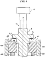
- An exemplary electrical bonding apparatus comprises: a first positioning member 7 for positioning a first bonding target member 3 with a cylindrical shape in a direction perpendicular to a central axis X-Y thereof; a second positioning member 8 for positioning a second bonding target member 4 having a hole portion 4A with a circular shape for receiving the first bonding target member 3 to align a central axis X-Y of the hole portion 4A of the second bonding target member 4 with the central axis X-Y of the first bonding target member 3; a bonding target member displacing device 7, 8 for relatively displacing the first and second bonding target members 3, 4 in a direction of the aligned central axes X-Y; a pressure device 12 for applying a pressing force to the first and second bonding target members 3, 4 for example as shown in FIG.
- the method of the third aspect for manufacturing a bonded article is a method according to the first aspect, wherein, as shown in FIG. 1A, FIG. 1B , FIG. 3 and FIG.
- the width of the bonded portion formed between the first and second bonding target members 3, 4 in the direction in which the first and second bonding target members are relatively displaced is determined by the position of the relative displacement amount setting portion 4D, 3J the first 3 or second bonding target member 4 and the position of the setting face 3F, 4E of the second 4 or first bonding target member 3 before the start of bonding and the thickness of the current conduction suppressing layer 5, 5A, 5B.
- one of the first and second bonding target members includes a relative displacement amount setting portion for setting the distance by which the bonding target portion of the first bonding target member and the bonding target portion of the second bonding target member are relatively displaced during bonding, and the other of them includes a setting face that is placed opposed to the relative displacement amount setting portion.
- a current conduction suppressing layer is provided on either one or both of the relative displacement amount setting portion and the setting face, which is brought into contact with the relative displacement amount setting portion, so that the relative displacement amount setting portion can contact the setting face via the current conduction suppressing layer during bonding.
- FIG. 1A shows a state in which no pressing force has been applied to a first bonding target member 3 and a second bonding target member 4 by a first bonding electrode 1 and a second bonding electrode 2, in other words, a state before bonding in which the first bonding target member 3 has been positioned and placed on the second bonding target member 4.
- FIG. 1B shows a state in which the first bonding target member 3 and the second bonding target member 4 have been electrically bonded to each other.
- central axis X-Y used in the description of embodiments of the present invention refers to a straight line extending in the direction in which the first bonding target member 3 and the second bonding target member 4 are pressed against each other, in other words, passing through the center of the first bonding target member 3 in the direction in which the first bonding target member 3 and the second bonding target member 4 are relatively displaced during bonding.
- a pressure device may be provided separately from the electrodes as shown in FIG. 4 , in which case it should be ensured that the electrodes closely contacts the bonding target members.
- the bonding target member may be clamped by an electrode at, for example, a face 3B.
- the electrode may be formed in a sheet-like shape or as a thin plate and interposed between a pressure portion of the pressure device and a bonding target member so that the electrode and the target member to be contacted thereto can closely contact each other.
- the first bonding target member 3 is made of a ferrous material containing carbon, for example.
- the first bonding target member 3 is circular in a cross-section perpendicular to its central axis X-Y, for example, and its external surface consists of a face 3A with which the first bonding electrode 1 will be brought into contact, a face 3B of a part with a large diameter extending in the same direction as the central axis X-Y, an inclined face 3C inclined toward the central axis X-Y from the face 3B, a face 3D of a part with an outside diameter that is slightly smaller than that of the part corresponding to the face 3B, an inclined face 3E inclined toward the central axis X-Y from the face 3D, a setting face 3F extending perpendicular to the central axis X-Y from the inclined face 3E, a face 3G of a small-diameter portion extending in the same direction as the central axis X-Y, and a free end
- the second bonding target member 4 is a cast iron casting containing carbon, for example.
- the second bonding target member 4 has a hole portion 4A, which is a through hole here.
- the hole portion 4A includes an inner face 4B having an inside diameter that is slightly larger than the outside diameter of the face 3B of the part with a large diameter of the first bonding target member 3, a part 4C that protrudes slightly toward the central axis X-Y from the inner face 4B and at least partially serves as a bonding target portion, and an annular relative displacement amount setting portion 4D extending perpendicular to the central axis X-Y and protruding toward the central axis X-Y beyond the part 4C.
- the annular relative displacement amount setting portion 4D has an inner face 4D1 extending almost parallel to the central axis X-Y.
- the inner face 4D1 of the relative displacement amount setting portion 4D has an inside diameter that is greater than the outside diameter of the face 3G of the small-diameter portion of the first bonding target member 3 and the relative displacement amount setting portion 4D therefore does not contact the first bonding target member 3.
- the reference numeral 4E designates a face on the entrance side of the hole portion 4A of the second bonding target member 4, in other words, the face on the side from which the first bonding target member is inserted, and the reference numeral 4F designates an end face located on the opposite side from the face 4E.
- the relative displacement amount setting portion 4D is preferably formed integrally with the rest of the second bonding target member 4 from the standpoint of mechanical strength.
- the degree of parallelization between the opposite faces of the setting face 3F of the first bonding target member 3 and the relative displacement amount setting portion 4D of the second bonding target member 4 is preferably high. In this case, an external force is applied evenly to the entire region between the setting face 3F and the relative displacement amount setting portion 4D. This helps to further improve the mechanical strength.
- the distance (dimension) by which the bonding target portion of the first bonding target member is pressed into the bonding target portion of the hole portion of the second bonding target member during bonding may vary because of some variation in shapes or dimensions of the first and second bonding target members or some variation in the pressing force or bonding current in the electrical bonding apparatus.
- the relative displacement amount setting portion 4D and the setting face 3F of the first bonding target member 3 regulates the relative displacement amount between the first and second bonding target members during bonding to be uniform or constant to make the bonding width of the bonded portion uniform or constant
- the relative displacement amount setting portion 4D and the setting face 3F also play an important role of reducing the variation in bonding strength to a very low level and making the bonding strength of the bonded articles almost uniform.
- a current conduction suppressing layer 5 is formed on a face 4D2 of the relative displacement amount setting portion 4D that abuts on the setting face 3F of the first bonding target member 3 during bonding.
- the current conduction suppressing layer 5 is provided to suppress current conduction so that the post-heating current does not substantially flow between the setting face 3F of the first bonding target member 3 and the relative displacement amount setting portion 4D of the second bonding target member 4 during tempering that is carried out after the first bonding target member 3 and the second bonding target member 4 are bonded to each other.
- the expression "not substantially flow” means that the current value flowing through the current conduction suppressing layer is relatively so small compared to the post-heating current flowing through the bonded portion as to be negligible.
- the current value flowing through the current conduction suppressing layer which needs to be smaller than the post-heating current flowing through the bonded portions, is preferably at most 1/3, more preferably at most 1/10, still more preferably at most 1/50, the post-heating current flowing through the bonded portions.
- the term "suppress" means not only to keep the current value low but also to prevent (insulate) current conduction.
- the current conduction suppressing layer 5 can be an electrically insulating film or sheet or a high-resistance thin plate that has such a material strength or thickness that its electrical insulation property or current conduction suppressing ability is not affected by the pressing force during the electrical bonding.
- the current conduction suppressing layer 5 may be made of a resistive material having a resistance that is sufficiently higher than the very low resistance of the bonded portion (herein, this is the meaning of the term "high-resistance") when the area of the bonded portion is large enough to allow passage of the peak value of the post-heating current for tempering.
- various things can be contemplated including an ALUMITE (trademark) (anodized aluminum) treated aluminum thin plate, a metal oxidation film formed by oxidation treatment of the face 4D2 of the relative displacement amount setting portion 4D, a ceramic thin plate, an electrically insulating coating film, a thin film or thin plate made of an electrically insulating resin or the like and having excellent mechanical strength.
- ALUMITE trademark
- anodized aluminum aluminum
- a ceramic thin plate As examples of the current conduction suppressing layer 5, various things can be contemplated including an ALUMITE (trademark) (anodized aluminum) treated aluminum thin plate, a metal oxidation film formed by oxidation treatment of the face 4D2 of the relative displacement amount setting portion 4D, a ceramic thin plate, an electrically insulating coating film, a thin film or thin plate made of an electrically insulating resin or the like and having excellent mechanical strength
- an electrically insulating material or resistive material having low elasticity is preferred and the use of an electrically insulating substance having high elasticity, such as rubber, as the current conduction suppressing layer 5 is not preferable.
- the thickness of the current conduction suppressing layer 5 is not limited, there are cases where a thin current conduction suppressing layer 5 is preferable from the standpoint of the cost or the determination of an initial distance (dimension) between the face 4D2 of the relative displacement amount setting portion 4D and the setting face 3F of the first bonding target member 3 when the current conduction suppressing layer 5 is, for example, a metal oxidation film formed by oxidation treatment of the face 4D2 of the relative displacement amount setting portion 4D although it depends on the surface roughness of the face 4D2 of the relative displacement amount setting portion 4D and the setting face 3F of the first bonding target member 3.
- the first bonding target member 3 is first positioned and placed on the second bonding target member 4 such that the face 3B of the first bonding target member 3 does not contact the inner face 4B of the hole portion 4A of the second bonding target member 4 and the inclined face 3C of the first bonding target member 3 contacts a corner portion of the part 4C of the second bonding target member 4 as shown in FIG. 1A .
- the distance between the setting face 3F of the first bonding target member 3 and the current conduction suppressing layer 5 is "H.”
- the distance H which is equal to the displacement amount by which the first bonding target member 3 and the second bonding target member 4 are relatively displaced during bonding, is an important element that determines the bonding width, in the direction of the central axis X-Y, of a bonded portion W shown in FIG. 1B .
- the relative displacement amount setting portion 4D is formed in such a position that this condition is fulfilled, in other words, in a position in the hole portion 4A of the second bonding target member 4 and the thickness of the current conduction suppressing layer 5 is determined, and the position of the setting face 3F of the first bonding target member 3 is determined accordingly.
- the corner portion of the part 4C is shown as a part with a right-angled cross-section in the drawing, but the right-angled corner may be cut away along the entire circumference of the part 4C to form an inclined face (chamfered face) or curved face (C-face).
- the inclined face 3C of the first bonding target member 3 is positioned and placed on the inclined face or curved face of the part 4C of the second bonding target member 4.
- the first bonding electrode 1 is moved along the central axis X-Y toward the second bonding electrode 2 until it comes into soft contact with the face 3A of the first bonding target member 3.
- the second bonding electrode 2 is in contact with the face 4F of the second bonding target member 4 to support the second bonding target member 4.
- the first bonding electrode 1 is moved along the central axis X-Y to apply a pressing force that increases along a predetermined curve to the first bonding target member 3.
- an electrical current is applied between the first bonding electrode 1 and the second bonding electrode 2 to apply a bonding current between the first bonding target member 3 and the second bonding target member 4.
- the corner portion of the part 4C functions as a projection.
- the temperature of the vicinity of the point where the inclined face 3C of the first bonding target member 3 is in contact with the corner portion of the part 4C of the second bonding target member 4 increases rapidly and their parts in contact with or abutting on each other undergo plastic flow.
- the relative displacement amount between the first bonding target member 3 and the second bonding target member 4 is equal to the distance H between the setting face 3F of the first bonding target member 3 and the current conduction suppressing layer 5 formed on the relative displacement amount setting portion 4D regardless of variation due to processing accuracy during manufacture of the first bonding target member 3 and the second bonding target member 4 or variation in the pressing force, the width of the bonded portion W is equal to the distance H.
- a tempering step is carried out. While the pressing force applied during the bonding step is continuously maintained at nearly a constant level, the pressing force may be once reduced to almost zero for solidification of the bonded portion W and then increased again along a predetermined curve when a post-heating current for tempering is applied.
- the post-heating current is applied after the bonded portion W between the first bonding target member 3 and the second bonding target member 4 is solidified. In the state shown in FIG. 1B , a post-heating current is applied to the first bonding target member 3 and the second bonding target member 4 through the first bonding electrode 1 and the second bonding electrode 2.
- the post-heating current does not substantially flow between the setting face 3F of the first bonding target member 3 and the relative displacement amount setting portion 4D of the second bonding target member 4 and almost all post-heating current flows between the first bonding target member 3 and the second bonding target member 4 through the bonded portion W.
- the relative displacement amount setting portion 4D even when the relative displacement amount setting portion 4D is provided, there is no need to apply a high post-heating current compared to the conventional cases and no unnecessary heat is generated between the setting face 3F of the first bonding target member 3 and the relative displacement amount setting portion 4D of the second bonding target member 4.
- the first bonding target member 3 and the second bonding target member 4 receive mechanical stress caused by vibrations or impact forces from the outside not only at the bonded portion W but also at the contact area between the setting face 3F of the first bonding target member 3 and the relative displacement amount setting portion 4D of the second bonding target member 4, the mechanical strength is improved compared to the case where the relative displacement amount setting portion 4D and the setting face 3F are not provided.
- the current conduction suppressing layer 5 may be provided on the setting face 3F of the first bonding target member 3.
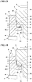
- FIG. 2 Another example of a basic embodiment of an electrical bonding method according to the present invention is next described with reference to FIG. 2 .
- the main difference of the first bonding target member 3 from that of the first embodiment lies in that it has a relative displacement amount setting portion 3J at its end part and a current conduction suppressing layer 5A is formed on an end face 3J1 thereof.
- the main difference of the second bonding target member 4 from that of the first embodiment lies in that it has a hole portion 4A which is a recess having a bottom shown as a bottom face 4G, and a current conduction suppressing layer 5B is formed on the bottom face 4G in the recess.
- the position of the relative displacement amount setting portion 3J relative to the bottom face 4G, the position of the end face 3J1 of the relative displacement amount setting portion 3J, and the thicknesses of the current conduction suppressing layer 5A and the current conduction suppressing layer 5B are determined such that the distance H between the current conduction suppressing layer 5A on the end face 3J1 of the relative displacement amount setting portion 3J and the current conduction suppressing layer 5B on the bottom face 4G is equal to the desired bonding width H of the bonded portion.
- the bottom face 4G in the recess plays the role of the setting face 3F of the first bonding target member 3 of the first embodiment.
- the position of the relative displacement amount setting portion 3J and the thicknesses of the current conduction suppressing layer 5A and the current conduction suppressing layer 5B are selected to determine the desired bonding width H of the bonded portion in view of the position of the bottom face 4G because the bottom face 4G in the recess is preliminarily determined in this second embodiment.
- the bottom face 4G of the recess serves a similar function to the setting face 3F described in the first embodiment, it may be referred to as "setting face.”
- the size and shape of the relative displacement amount setting portion 3J in the direction perpendicular to the central axis X-Y are not limited as long as the relative displacement amount setting portion 3J has a diameter that is equal to or smaller than the diameter of the face 3D of the first bonding target member 3, the relative displacement amount setting portion 3J advantageously has a circular shape with nearly the same diameter as the face 3D for improvement of mechanical strength against vibration and so on.
- the degree of parallelization between the current conduction suppressing layer 5A and the current conduction suppressing layer 5B is preferably high so that their entire faces can closely contact each other.
- the bonding method is not described in detail because it is almost the same as that of the first embodiment.
- the current conduction suppressing layer 5A and the current conduction suppressing layer 5B approach each other as the bonding width of the bonded portion increases in the bonding process, and a bonded portion with a predetermined bonding width H as described in the first embodiment is formed and the bonding step is completed when the current conduction suppressing layer 5A and the current conduction suppressing layer 5B contact each other.
- a post-heating current is applied to the first bonding target member 3 and the second bonding target member 4 through the first bonding electrode 1 and the second bonding electrode 2 as described above.
- the current conduction suppressing layer 5A and the current conduction suppressing layer 5B prevent a portion of the post-heating current from flowing between the relative displacement amount setting portion 3J of the first bonding target member 3 and the bottom shown as the bottom face 4G of the second bonding target member 4, substantially all the post-heating current flows through the bonded portion between the first bonding target member 3 and the second bonding target member 4, resulting in stable tempering.
- the bonded portion between the first bonding target member 3 and the second bonding target member 4, and the bottom portion with the relative displacement amount setting portion 3J of the first bonding target member 3 and the bottom face 4G of the second bonding target member 4 receive vibrations or impact forces from the outside.
- the bonded article has high mechanical strength compared to the case where vibrations or impact forces from the outside are received only by the bonded portion between the first bonding target member 3 and the second bonding target member 4.
- almost all post-heating current flows through the bonded portion between the first bonding target member 3 and the second bonding target member 4.
- stable tempering can be achieved without the need to use a particularly higher post-heating current than in a conventional method.
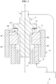
- FIG. 3 shows a state before electrical bonding in which the first bonding target member 3 has been positioned and placed on the second bonding target member 4 with the first bonding electrode 1 in a light contact with an upper face of the first bonding target member 3 and a cylindrical large-thickness second bonding electrode 2 supporting a large-thickness short cylindrical second bonding target member 4.
- the first bonding electrode 1 and the second bonding electrode 2 are connected to an electrical bonding power source 6.
- the first bonding target member 3 is positioned on the second bonding target member 4 by a positioning member 7, and, similarly, the second bonding target member 4 is positioned on the second bonding electrode 2 by a positioning member 8.
- the first positioning member 7 is a member for determining the position of the first bonding target member 3 in a direction perpendicular to the X-Y axis.
- the second positioning member 8 determines the position of the second bonding target member 4 in a direction perpendicular to the X-Y axis, and its position in a direction perpendicular to the X-Y axis relative to the first positioning member 7 is determined.
- the relative positions of the first bonding target member 3 and the second bonding target member 4 in a direction perpendicular to the X-Y axis are determined by the first positioning member 7 and the second positioning member 8.
- first positioning member 7 and the second positioning member 8 may be also applied to the first and second embodiments.
- Either one of the first positioning member 7 and the second positioning member 8 may be fixed to the electrical bonding apparatus, and the position of the other can be relatively determined with respect to the position of the fixed one.
- the first bonding target member 3 includes a relative displacement amount setting portion 3J, which has the shape of a large-thickness plate and functions as described above, at a position that is located outside the hole portion 4A of the second bonding target member 4.
- the relative displacement amount setting portion 3J has such a thickness that it is not deformed or broken under the pressing force during bonding and tempering.
- the relative displacement amount setting portion 3J is preferably formed integrally with the rest of the first bonding target member 3 from the standpoint of mechanical strength.
- a current conduction suppressing layer 5, which is similar to that described in the first embodiment, is formed on a face 3J1 of the relative displacement amount setting portion 3J that is placed opposite to or facing a face 4E of the second bonding target member 4.
- the face 4E of the second bonding target member 4 serves a similar function to the setting face 3F described in the first embodiment, it may be referred to as "setting face.”
- the positioning members 7 and 8 have almost the same structure, and are constituted of two or more identical members that can be moved inward and outward in a direction perpendicular to the central axis X-Y, for example.
- the positioning member 8 has been expanded radially outward when the second bonding target member 4 is placed on an upper face of the second bonding electrode 2.
- the second bonding target member 4 is placed on an upper face of the second bonding electrode 2.
- the positioning member 8 is contracted radially inward to position the second bonding target member 4 in a predetermined position on the second bonding electrode 2.
- the positioning member 7 performs a contracting operation to position the first bonding target member 3 such that a corner portion of a bonding target portion shown as the face 3B of the first bonding target member 3 is located evenly on an inclined face 4H of the second bonding target member 4.
- the distance between the setting face 4E of the second bonding target member 4 and the current conduction suppressing layer 5 is equal to a predetermined distance H.
- Either one or both of the first bonding electrode 1 and the second bonding electrode 2 can be moved relatively in a direction toward or away from each other along the central axis X-Y of the first bonding target member 3 by a pressure-drive mechanism 12 shown in FIG. 4 .
- the pressure-drive mechanism 12 is actuated and drives either one or both of the first bonding electrode 1 and the second bonding electrode 2 in such a direction that the distance between the first bonding electrode 1 and the second bonding electrode 2 decreases to increase the pressing force on the first bonding target member 3 and the second bonding target member 4.
- the electrical bonding power source 6 supplies a bonding current to the first bonding target member 3 and the second bonding target member 4 via the first bonding electrode 1 and the second bonding electrode 2.
- the bonding current induces solid phase bonding between the first bonding target member 3 and the second bonding target member 4, and the first bonding electrode 1 and the second bonding electrode 2 stop moving and the bonding step is ended when the current conduction suppressing layer 5 formed on the relative displacement amount setting portion 3J contacts the face 4E of the second bonding target member 4.
- the pressure-drive mechanism stops operation and maintains the pressing force between the first bonding target member 3 and the second bonding target member 4 at an almost constant level for the subsequent tempering.
- the pressure-drive mechanism 12 relatively displaces the first bonding target member 3 and the second bonding target member 4 via the first bonding electrode 1 and/or the second bonding electrode 2, in other words, serves as a bonding target member displacing device.
- the positioning member 7 or 8 may be configured to displace in the direction of the central axis X-Y after contracting radially inward to clamp a bonding target member to displace the bonding target member.
- the "displacement" is the displacement necessary to bringing the first bonding target member 3 and the second bonding target member 4 into contact with each other before the application of pressure.
- the positioning member 7 and/or 8 may be regarded as functioning as a bonding target member displacing device because the positioning member 7 and/or 8 displace a bonding target member.
- the pressure-drive mechanism 12 functions as a bonding target member displacing device.
- the pressure-drive mechanism 12 may be constituted integrally with the first bonding electrode 1 and/or the second bonding electrode 2.
- the electrical bonding power source 6 supplies a post-heating current to the first bonding target member 3 and the second bonding target member 4 via the first bonding electrode 1 and the second bonding electrode 2. At this time, the post-heating current is substantially prevented from flowing between the relative displacement amount setting portion 3J of the first bonding target member 3 and the face 4E of the second bonding target member 4 by the current conduction suppressing layer 5 and flows through the bonded portion formed between the first bonding target member 3 and the second bonding target member 4.
- a bonded part including and in the vicinity of the bonded portion between the first bonding target member 3 and the second bonding target member 4 is stably tempered.
- the electrical bonding is completed when the pressure-drive mechanism 12 moves either one or both of the first bonding electrode 1 and the second bonding electrode 2 in a direction away from each other.
- the electrical bonding power source 6 shown in FIG. 3 may be the one shown in FIG. 1 of the above-mentioned Patent Document 1, the one shown in FIG. 3 and FIG. 4 of the above-mentioned Patent Document 2, or any known power source, the waveform of the bonding current and post-heating current can be adjusted and the electrical bonding can be therefore carried out more effectively when the power source shown in FIG. 1 of the above-mentioned Patent Document 1 is used.
- the first bonding electrode 1 has such a structure as to contact an upper face of the first bonding target member 3
- the first bonding electrode 1 may have such a shape as to directly contact an upper face of the relative displacement amount setting portion 3J of the first bonding target member 3 so that the pressing force can be directly applied to the upper face of the relative displacement amount setting portion 3J.
- the shapes of the first bonding target member 3 and the second bonding target member 4 are not limited to those of the above-mentioned first to second embodiments as long as either one of them includes a relative displacement amount setting portion, a setting face and a current conduction suppressing layer 5 that fulfill the above-mentioned conditions.
- the bonding target members to be bonded by electrical bonding are solid-phase bonded while both of them are in a plastic flow state in the embodiments of the present invention
- the metal materials that have undergone plastic flow are slightly pushed out as described above.
- the inclined face 3E or the like is formed on the first bonding target member 3 as shown in FIG. 1A, FIG.1B to form a space between the first bonding target member 3 and the second bonding target member 4 in the vicinity of the bonded portion, the metals that have undergone plastic flow are received in the space. This helps to achieve a good electrical bonding result.
- the present invention is not limited to specific metal materials.
- the first bonding target member 3 and the second bonding target member 4 are preferably made of metal materials having the same plastic flow temperature or having relatively close plastic flow temperatures from the standpoint of being able to carry out good ring mash bonding. Further, because the first bonding target member 3 is located at the center during bonding and can therefore emit less heat than the second bonding target member 4, good bonding strength can be achieved when the first bonding target member 3 is made of a metal material having the same plastic flow temperature as the second bonding target member 4 or a metal material having a slightly higher plastic flow temperature than the second bonding target member.
- the inclined face 3C of the first bonding target member 3 in an embodiment of the present invention may be either a linear inclined face or a curved inclined face (C-face). It is not necessarily an inclined face. Because even when the surfaces of the overlap allowance between the part shown as the face 3B of the first bonding target member 3 and the part shown as the part 4C of the second bonding target member 4 are both flat, no problem occurs when the first bonding target member 3 is placed on the second bonding target member 4 during bonding, since the area of the overlapping surfaces is small.
- the inclined face 4H of the second bonding target member is the same as the inclined face 3C in this regard.
- the corner portion of the part 4C of the second bonding target member 4 in the second embodiment may be either an inclined face or curved face (C-face).
- the corner portion of the bonding target portion shown as the face 3B of the first bonding target member 3 in FIG. 3 may also be an inclined face or curved face (C-face) as described above.
- the second bonding target member 4 While the second bonding target member 4 is placed on the second bonding electrode 2 in each embodiment described above, the second bonding target member 4 may be placed on a mounting table (not shown). In this case, after the first bonding target member 3 is set on the second bonding target member 4 as described above, the second bonding electrode 2, which moves upward from the lower side of each drawing, receives the second bonding target member 4 and the first bonding target member 3 from the mounting table (not shown) and moves upward to sandwich the first bonding target member 3 and the second bonding target member 4 between the first bonding electrode 1 and the second bonding electrode 2 to apply a pressure to the first bonding target member 3 and the second bonding target member 4.
- a method for manufacturing a bonded article as the embodiment of the present invention is described with reference to the flowchart of FIG. 5 .
- description is made of the case of the embodiment shown in FIG. 1A, FIG. 1B .
- the positioning members refer to FIG. 3 .
- the electrical bonding apparatus is activated (S1), and the first bonding target member 3 is provided to the electrical bonding apparatus (S2).
- the first bonding target member 3 has the setting face 3F, which will be placed opposed to the relative displacement amount setting portion 4D of the second bonding target member, which is described next.
- the second bonding target member 4 is provided to the electrical bonding apparatus (S3).
- the second bonding target member 4 has the hole portion 4A for receiving a part of the first bonding target member 3, and the relative displacement amount setting portion 4D.
- the current conduction suppressing layer 5 is formed on the relative displacement amount setting portion 4D ( FIG. 1A, FIG. 1B and FIG. 2 ).
- the current conduction suppressing layer may be formed on the first bonding target member 3 or on both the first bonding target member 3 and the second bonding target member 4 (5A, 5B ( FIG. 2 ), 5 ( FIG. 3 ).
- the provided first and second bonding target members 3 and 4 are positioned (S4).
- the second bonding target member 4 is placed on an upper face of the second bonding electrode 2 with the positioning member 8 having been expanded radially outward. Then, the positioning member 8 is contracted radially inward to position the second bonding target member 4 in a predetermined position on the second bonding electrode 2.
- the first bonding target member 3 is placed on the second bonding target member 4 with the positioning member 7 having been expanded radially outward. Then, the positioning member 7 performs a contracting operation to position the first bonding target member 3 such that a corner portion of a bonding target portion shown as the face 3B of the first bonding target member 3 is located evenly on the inclined face 4H of the second bonding target member 4.
- the positioning member 7 may perform a contracting operation before the first bonding target member 3 is placed on the second bonding target member 4.
- the positioning member 7 may be displaced downward in the drawing after clamping the first bonding target member 3 to bring the first bonding target member 3 into contact with the second bonding target member 4.
- the first bonding target member 3 is positioned such that the corner portion of the bonding target portion of the first bonding target member 3 is located on the inclined face 4H of the second bonding target member 4.
- the first and second bonding target members are relatively displaced until the relative displacement amount setting portion 4D and the setting face 3F contacts each other via the current conduction suppressing layer 5 (S7).
- the displacement is accomplished by the pressure-drive mechanism 12 ( FIG. 4 ).
- the current conduction suppressing layer 5 contacts the second bonding target member 4, the first bonding electrode 1 and the second bonding electrode 2 stop moving. At this time, the power supply is once interrupted. In this way, solid phase bonding is achieved between the bonding target members.
- a post-heating current is applied to the first and second bonding target members (S8).
- the bonded part is tempered by the flow of the post-heating current.
- the current conduction suppressing layer suppresses the amount of current that flows through the relative displacement amount setting portion 4D and the setting face 3F.
- the displacement amount H of the bonded portion formed between the first bonding target member 3 and the second bonding target member 4 in the relative displacement direction of the first and second bonding target members 3 and 4 may be determined by the position of the relative displacement amount setting portion of the first bonding target member 3 or the second bonding target member 4 and the position of the setting face of the second bonding target member 4 or the first bonding target member 3 before the start of bonding and the thickness of the current conduction suppressing layer 5.
- the distance H is equal to the displacement amount by which the first bonding target member 3 and the second bonding target member 4 are relatively displaced during bonding.
- the electrical bonding method according to a first implement of the present invention is an electrical bonding method in which a pressing force and a bonding current are applied between a second bonding target member having a hole portion for receiving a part of a first bonding target member and the first bonding target member to electrically bond the first and second bonding target members, and then a post-heating current is applied to the bonded first and second bonding target members for tempering, characterized in that the first or second bonding target member has a relative displacement amount setting portion for setting the distance by which a bonding target portion of the first bonding target member and a bonding target portion of the second bonding target member are relatively displaced during bonding; the second or first bonding target member has a setting face that is placed opposed to the relative displacement amount setting portion; either one or both of the relative displacement amount setting portion of the first or second bonding target member and the setting face of the second or first bonding target member has a current conduction suppressing layer formed thereon so that the relative displacement amount setting portion can contact the setting face of the first
- the electrical bonding apparatus is an electrical bonding apparatus including a first bonding electrode and a second bonding electrode for applying a pressing force and a bonding current between a second bonding target member having a hole portion for receiving a part of a first bonding target member and the first bonding target member to electrically bond the first and second bonding target members, and applying a post-heating current to the electrically bonded first and second bonding target members for tempering, characterized in that the first or second bonding target member has a relative displacement amount setting portion for setting the distance by which a bonding target portion of the first bonding target member and a bonding target portion of the second bonding target member are relatively displaced during bonding; the second or first bonding target member has a setting face that is placed opposed to the relative displacement amount setting portion of the first or second bonding target member; either one or both of the relative displacement amount setting portion of the first or second bonding target member and the setting face of the second or first bonding target member has a current conduction suppressing layer provided thereon
- the electrical bonding method or electrical bonding apparatus is characterized, in the first or second implement, in that the width of the bonded portion formed between the first and second bonding target members in the direction in which the first and second bonding target members are relatively displaced is determined by the position of the relative displacement amount setting portion of the first or second bonding target member and the position of the setting face of the second or first bonding target member before the start of bonding and the thickness of the current conduction suppressing layer.
- the present invention can be applied to obtain various bonded articles, and, in particular, to electrical bonding of a bonding target member used as a component part of an automobile e.g. which is exposed to significant vibrations or impact forces.
Landscapes
- Engineering & Computer Science (AREA)
- Mechanical Engineering (AREA)
- Chemical & Material Sciences (AREA)
- Physics & Mathematics (AREA)
- Thermal Sciences (AREA)
- Crystallography & Structural Chemistry (AREA)
- Materials Engineering (AREA)
- Metallurgy (AREA)
- Organic Chemistry (AREA)
- Pressure Welding/Diffusion-Bonding (AREA)
Claims (2)
- Verfahren zur Herstellung eines verbundenen Artikels, mit den Schritten:Bereitstellen eines ersten Verbindungszielements (3);Bereitstellen eines zweiten Verbindungszielements (4) zum Verbinden mit dem ersten Verbindungszielement (3), wobei das zweite Verbindungszielement (4) einen Lochabschnitt (4A) zur Aufnahme eines Teils des ersten Verbindungszielements (3) hat,wobei das erste oder das zweite Verbindungszielement (3, 4) einen Relativversatzbetrag-Einstellabschnitt (4D) zum Einstellen der Distanz hat, um die ein Verbindungszielabschnitt des ersten Verbindungszielements (3) und ein Verbindungszielabschnitt (4C) des zweiten Verbindungszielements (4) während des Verbindens relativ versetzt werden,wobei das zweite oder das erste Verbindungszielement (3, 4) eine Einstellfläche hat, die entgegengesetzt zu dem Relativversatzbetrag-Einstellabschnitt platziert ist,wobei eines oder beide von dem Relativversatzbetrag-Einstellabschnitt des ersten oder zweiten Verbindungszielements (3, 4) und der Einstellfläche des zweiten oder ersten Verbindungszielements (3, 4) eine darauf gebildete Stromleitungsunterbindungsschicht (5) zum Unterbinden des Leitens von Strom haben, so dass der Relativversatzbetrag-Einstellabschnitt die Einstellfläche des ersten oder zweiten Verbindungszielements (3, 4) über die Stromleitungsunterbindungsschicht (5) während des Verbindens kontaktieren kann;Anwenden einer Druckkraft auf das erste und das zweite Verbindungszielement (3, 4);relatives Versetzen des ersten und des zweiten Verbindungszielements (3, 4), bis der Relativversatzbetrag-Einstellabschnitt und die Einstellfläche einander über die Stromleitungsunterbindungsschicht (5) kontaktieren, während des Verbindens, wenn ein Verbindungsstrom auf dem ersten und dem zweiten Verbindungszielement (3, 4) angelegt wird, auf welche die Druckkraft angewandt ist, um einen verbundenen Abschnitt zu bilden; undAnwenden eines Nach-Erhitzungs-Stroms auf das erste und das zweite Verbindungszielement (3, 4) nach dem Schritt des Versetzens, wobei der Nach-Erhitzungs-Strom im Wesentlichen nur durch einen zwischen dem ersten und dem zweiten Verbindungszielement (3, 4) gebildeten, verbundenen Abschnitt fließt, um einen verbundenen Teil des verbundenen Abschnitts zu tempern.
- Verfahren zur Herstellung eines verbundenen Artikels gemäß Anspruch 1,
wobei die Breite des zwischen dem ersten und dem zweiten Verbindungszielement (3, 4) gebildeten verbundenen Abschnitts in der Richtung, in der das erste und das zweite Verbindungszielement (3, 4) relativ versetzt sind, durch die Position des Relativversatzbetrags-Einstellabschnitts des ersten oder zweiten Verbindungszielements (3, 4) und die Position der Einstellfläche des zweiten oder ersten Verbindungszielements (3, 4) vor Beginn des Verbindens und die Dicke der Stromleitungsunterbindungsschicht (5) bestimmt ist.
Applications Claiming Priority (2)
| Application Number | Priority Date | Filing Date | Title |
|---|---|---|---|
| JP2014208997 | 2014-10-10 | ||
| PCT/JP2015/076780 WO2016056386A1 (ja) | 2014-10-10 | 2015-09-18 | 電気接合方法及び電気接合装置 |
Publications (3)
| Publication Number | Publication Date |
|---|---|
| EP3205437A1 EP3205437A1 (de) | 2017-08-16 |
| EP3205437A4 EP3205437A4 (de) | 2018-01-17 |
| EP3205437B1 true EP3205437B1 (de) | 2019-04-17 |
Family
ID=55653004
Family Applications (1)
| Application Number | Title | Priority Date | Filing Date |
|---|---|---|---|
| EP15849434.4A Not-in-force EP3205437B1 (de) | 2014-10-10 | 2015-09-18 | Elektrisches verbindungsverfahren und elektrische verbindungsvorrichtung |
Country Status (6)
| Country | Link |
|---|---|
| US (1) | US9925615B2 (de) |
| EP (1) | EP3205437B1 (de) |
| JP (1) | JP6009690B2 (de) |
| KR (1) | KR101814354B1 (de) |
| CN (1) | CN106715028B (de) |
| WO (1) | WO2016056386A1 (de) |
Families Citing this family (8)
| Publication number | Priority date | Publication date | Assignee | Title |
|---|---|---|---|---|
| JP6503209B2 (ja) * | 2015-03-27 | 2019-04-17 | 株式会社オーハシテクニカ | 圧入接合による接合品の製造方法 |
| DE102016212469A1 (de) * | 2016-07-08 | 2018-01-11 | Robert Bosch Gmbh | Verfahren zur Herstellung einer Kraftstoffhochdruckpumpe |
| JP6873777B2 (ja) * | 2017-03-28 | 2021-05-19 | 本田技研工業株式会社 | 金属部材の接合方法 |
| JP7111076B2 (ja) * | 2019-07-30 | 2022-08-02 | トヨタ自動車株式会社 | 抵抗溶接装置 |
| JP7649165B2 (ja) * | 2021-02-26 | 2025-03-19 | 日東精工株式会社 | 絶縁複合部品および絶縁複合部品の製造方法 |
| JP7673529B2 (ja) * | 2021-07-08 | 2025-05-09 | マツダ株式会社 | 金属部材の接合方法 |
| JP2023009961A (ja) * | 2021-07-08 | 2023-01-20 | マツダ株式会社 | 金属部材の接合方法及び金属部材の接合構造 |
| CN116275449B (zh) * | 2023-05-15 | 2023-08-29 | 杭州沈氏节能科技股份有限公司 | 基于位移量控制的扩散焊接炉及其控制方法 |
Family Cites Families (9)
| Publication number | Priority date | Publication date | Assignee | Title |
|---|---|---|---|---|
| US4922072A (en) * | 1988-06-22 | 1990-05-01 | Methode Electronics, Inc. | Wire connecting method |
| JPH06137273A (ja) | 1992-10-28 | 1994-05-17 | Origin Electric Co Ltd | コンプレッサ容器およびその製造方法 |
| JP3644831B2 (ja) * | 1998-10-05 | 2005-05-11 | オリジン電気株式会社 | 抵抗溶接装置及び溶接方法 |
| JP3648092B2 (ja) | 1999-05-24 | 2005-05-18 | オリジン電気株式会社 | コンデンサ式抵抗溶接方法及び装置 |
| JP2004017048A (ja) | 2002-06-12 | 2004-01-22 | Origin Electric Co Ltd | リングマッシュ溶接方法及び装置 |
| JP2007030013A (ja) * | 2005-07-29 | 2007-02-08 | Hitachi Ltd | 通電接合方法及び装置 |
| JP5399206B2 (ja) * | 2009-11-04 | 2014-01-29 | マツダ株式会社 | 金属部材の接合方法および金属接合体 |
| JP5512395B2 (ja) * | 2010-05-27 | 2014-06-04 | マツダ株式会社 | 金属部材の接合方法 |
| CN103260808A (zh) * | 2010-12-15 | 2013-08-21 | 日产自动车株式会社 | 接合方法及被接合构件 |
-
2015
- 2015-09-18 CN CN201580051355.6A patent/CN106715028B/zh not_active Expired - Fee Related
- 2015-09-18 WO PCT/JP2015/076780 patent/WO2016056386A1/ja not_active Ceased
- 2015-09-18 EP EP15849434.4A patent/EP3205437B1/de not_active Not-in-force
- 2015-09-18 JP JP2015548087A patent/JP6009690B2/ja not_active Expired - Fee Related
- 2015-09-18 KR KR1020177007815A patent/KR101814354B1/ko not_active Expired - Fee Related
- 2015-09-18 US US15/513,894 patent/US9925615B2/en active Active
Non-Patent Citations (1)
| Title |
|---|
| None * |
Also Published As
| Publication number | Publication date |
|---|---|
| CN106715028B (zh) | 2018-05-08 |
| EP3205437A1 (de) | 2017-08-16 |
| KR20170066350A (ko) | 2017-06-14 |
| KR101814354B1 (ko) | 2018-01-30 |
| JP6009690B2 (ja) | 2016-10-19 |
| JPWO2016056386A1 (ja) | 2017-04-27 |
| EP3205437A4 (de) | 2018-01-17 |
| WO2016056386A1 (ja) | 2016-04-14 |
| CN106715028A (zh) | 2017-05-24 |
| US9925615B2 (en) | 2018-03-27 |
| US20170282282A1 (en) | 2017-10-05 |
Similar Documents
| Publication | Publication Date | Title |
|---|---|---|
| EP3205437B1 (de) | Elektrisches verbindungsverfahren und elektrische verbindungsvorrichtung | |
| US11045898B2 (en) | Friction stir spot welding method and friction stir spot welding apparatus | |
| CN102834215B (zh) | 电阻焊接结构与电阻焊接方法和被焊接部件及其制造方法 | |
| CN105689873A (zh) | 用于借助辅助元件热接合构件的方法 | |
| CN106413969B (zh) | 用于接合复合板构件与功能元件的方法和装置 | |
| CN106715026B (zh) | 用于接合复合板构件与另外的构件的方法和装置 | |
| US20090208772A1 (en) | Method of welding three metal sheets and apparatus with three stacked metal sheets | |
| JP4694873B2 (ja) | 圧入接合方法及び圧入接合部品 | |
| KR100501655B1 (ko) | 알루미늄판재 접합용 자기압입 마찰리벳 및 이것을 이용한알루미늄판재의 접합방법 | |
| KR102394629B1 (ko) | 핫스탬핑 강판의 접합방법 | |
| JP2009068640A (ja) | 樹脂プーリ付き軸受 | |
| KR20160013195A (ko) | 전자 클러치 | |
| JP6516247B2 (ja) | 片側スポット溶接方法 | |
| JP6873777B2 (ja) | 金属部材の接合方法 | |
| US9849539B2 (en) | Bonded article and method for manufacturing bonded article | |
| US20150273619A1 (en) | Welding apparatus and welding method | |
| US11484963B2 (en) | Fitting member, annular member, joined member and method of manufacturing joined member | |
| CN112638567A (zh) | 用于制造在由不同金属制成的两个构件之间的至少一个限定的连接层的方法 | |
| JP7334561B2 (ja) | 突合せ溶接方法及びその装置 | |
| CN110653468A (zh) | 接合装置和接合方法 | |
| CN101837510A (zh) | 封板的感应焊接组件 | |
| JP3447891B2 (ja) | 条材端面を平坦面に接合する方法 | |
| WO2016047619A1 (ja) | 接合体、磁気回転アーク接合方法および接合体の製造方法 | |
| KR101595187B1 (ko) | 일면 압흔 방지용 점용접장치 및 일면 압흔 방지용 점용접방법 | |
| JP2015231633A (ja) | ろう付けを用いたワークの製造方法 |
Legal Events
| Date | Code | Title | Description |
|---|---|---|---|
| STAA | Information on the status of an ep patent application or granted ep patent |
Free format text: STATUS: THE INTERNATIONAL PUBLICATION HAS BEEN MADE |
|
| PUAI | Public reference made under article 153(3) epc to a published international application that has entered the european phase |
Free format text: ORIGINAL CODE: 0009012 |
|
| STAA | Information on the status of an ep patent application or granted ep patent |
Free format text: STATUS: REQUEST FOR EXAMINATION WAS MADE |
|
| 17P | Request for examination filed |
Effective date: 20170324 |
|
| AK | Designated contracting states |
Kind code of ref document: A1 Designated state(s): AL AT BE BG CH CY CZ DE DK EE ES FI FR GB GR HR HU IE IS IT LI LT LU LV MC MK MT NL NO PL PT RO RS SE SI SK SM TR |
|
| AX | Request for extension of the european patent |
Extension state: BA ME |
|
| A4 | Supplementary search report drawn up and despatched |
Effective date: 20171214 |
|
| DAV | Request for validation of the european patent (deleted) | ||
| DAX | Request for extension of the european patent (deleted) | ||
| RIC1 | Information provided on ipc code assigned before grant |
Ipc: B23K 11/02 20060101AFI20171208BHEP Ipc: B23K 11/24 20060101ALI20171208BHEP Ipc: B23K 101/00 20060101ALN20171208BHEP Ipc: B23K 11/14 20060101ALI20171208BHEP Ipc: B23K 11/11 20060101ALI20171208BHEP Ipc: B23K 11/26 20060101ALI20171208BHEP Ipc: B23K 33/00 20060101ALI20171208BHEP |
|
| RIC1 | Information provided on ipc code assigned before grant |
Ipc: B23K 33/00 20060101ALI20180629BHEP Ipc: B23K 11/14 20060101ALI20180629BHEP Ipc: B23K 11/02 20060101AFI20180629BHEP Ipc: B23K 101/00 20060101ALN20180629BHEP Ipc: B23K 11/11 20060101ALI20180629BHEP Ipc: B23K 11/26 20060101ALI20180629BHEP Ipc: B23K 11/24 20060101ALI20180629BHEP |
|
| RIC1 | Information provided on ipc code assigned before grant |
Ipc: B23K 11/24 20060101ALI20180719BHEP Ipc: B23K 11/02 20060101AFI20180719BHEP Ipc: B23K 101/00 20060101ALN20180719BHEP Ipc: B23K 11/11 20060101ALI20180719BHEP Ipc: B23K 11/26 20060101ALI20180719BHEP Ipc: B23K 33/00 20060101ALI20180719BHEP Ipc: B23K 11/14 20060101ALI20180719BHEP |
|
| GRAP | Despatch of communication of intention to grant a patent |
Free format text: ORIGINAL CODE: EPIDOSNIGR1 |
|
| STAA | Information on the status of an ep patent application or granted ep patent |
Free format text: STATUS: GRANT OF PATENT IS INTENDED |
|
| INTG | Intention to grant announced |
Effective date: 20180827 |
|
| GRAJ | Information related to disapproval of communication of intention to grant by the applicant or resumption of examination proceedings by the epo deleted |
Free format text: ORIGINAL CODE: EPIDOSDIGR1 |
|
| STAA | Information on the status of an ep patent application or granted ep patent |
Free format text: STATUS: REQUEST FOR EXAMINATION WAS MADE |
|
| INTC | Intention to grant announced (deleted) | ||
| RIC1 | Information provided on ipc code assigned before grant |
Ipc: B23K 11/26 20060101ALI20190121BHEP Ipc: B23K 11/14 20060101ALI20190121BHEP Ipc: B23K 101/00 20060101ALN20190121BHEP Ipc: B23K 11/02 20060101AFI20190121BHEP Ipc: B23K 11/24 20060101ALI20190121BHEP Ipc: B23K 11/11 20060101ALI20190121BHEP Ipc: B23K 33/00 20060101ALI20190121BHEP |
|
| GRAR | Information related to intention to grant a patent recorded |
Free format text: ORIGINAL CODE: EPIDOSNIGR71 |
|
| GRAS | Grant fee paid |
Free format text: ORIGINAL CODE: EPIDOSNIGR3 |
|
| STAA | Information on the status of an ep patent application or granted ep patent |
Free format text: STATUS: GRANT OF PATENT IS INTENDED |
|
| GRAA | (expected) grant |
Free format text: ORIGINAL CODE: 0009210 |
|
| STAA | Information on the status of an ep patent application or granted ep patent |
Free format text: STATUS: THE PATENT HAS BEEN GRANTED |
|
| AK | Designated contracting states |
Kind code of ref document: B1 Designated state(s): AL AT BE BG CH CY CZ DE DK EE ES FI FR GB GR HR HU IE IS IT LI LT LU LV MC MK MT NL NO PL PT RO RS SE SI SK SM TR |
|
| INTG | Intention to grant announced |
Effective date: 20190311 |
|
| REG | Reference to a national code |
Ref country code: GB Ref legal event code: FG4D |
|
| REG | Reference to a national code |
Ref country code: CH Ref legal event code: EP |
|
| REG | Reference to a national code |
Ref country code: DE Ref legal event code: R096 Ref document number: 602015028649 Country of ref document: DE |
|
| REG | Reference to a national code |
Ref country code: AT Ref legal event code: REF Ref document number: 1121010 Country of ref document: AT Kind code of ref document: T Effective date: 20190515 Ref country code: IE Ref legal event code: FG4D |
|
| REG | Reference to a national code |
Ref country code: NL Ref legal event code: MP Effective date: 20190417 |
|
| REG | Reference to a national code |
Ref country code: LT Ref legal event code: MG4D |
|
| PG25 | Lapsed in a contracting state [announced via postgrant information from national office to epo] |
Ref country code: NL Free format text: LAPSE BECAUSE OF FAILURE TO SUBMIT A TRANSLATION OF THE DESCRIPTION OR TO PAY THE FEE WITHIN THE PRESCRIBED TIME-LIMIT Effective date: 20190417 |
|
| PG25 | Lapsed in a contracting state [announced via postgrant information from national office to epo] |
Ref country code: PT Free format text: LAPSE BECAUSE OF FAILURE TO SUBMIT A TRANSLATION OF THE DESCRIPTION OR TO PAY THE FEE WITHIN THE PRESCRIBED TIME-LIMIT Effective date: 20190817 Ref country code: AL Free format text: LAPSE BECAUSE OF FAILURE TO SUBMIT A TRANSLATION OF THE DESCRIPTION OR TO PAY THE FEE WITHIN THE PRESCRIBED TIME-LIMIT Effective date: 20190417 Ref country code: ES Free format text: LAPSE BECAUSE OF FAILURE TO SUBMIT A TRANSLATION OF THE DESCRIPTION OR TO PAY THE FEE WITHIN THE PRESCRIBED TIME-LIMIT Effective date: 20190417 Ref country code: HR Free format text: LAPSE BECAUSE OF FAILURE TO SUBMIT A TRANSLATION OF THE DESCRIPTION OR TO PAY THE FEE WITHIN THE PRESCRIBED TIME-LIMIT Effective date: 20190417 Ref country code: SE Free format text: LAPSE BECAUSE OF FAILURE TO SUBMIT A TRANSLATION OF THE DESCRIPTION OR TO PAY THE FEE WITHIN THE PRESCRIBED TIME-LIMIT Effective date: 20190417 Ref country code: FI Free format text: LAPSE BECAUSE OF FAILURE TO SUBMIT A TRANSLATION OF THE DESCRIPTION OR TO PAY THE FEE WITHIN THE PRESCRIBED TIME-LIMIT Effective date: 20190417 Ref country code: NO Free format text: LAPSE BECAUSE OF FAILURE TO SUBMIT A TRANSLATION OF THE DESCRIPTION OR TO PAY THE FEE WITHIN THE PRESCRIBED TIME-LIMIT Effective date: 20190717 Ref country code: LT Free format text: LAPSE BECAUSE OF FAILURE TO SUBMIT A TRANSLATION OF THE DESCRIPTION OR TO PAY THE FEE WITHIN THE PRESCRIBED TIME-LIMIT Effective date: 20190417 |
|
| PG25 | Lapsed in a contracting state [announced via postgrant information from national office to epo] |
Ref country code: PL Free format text: LAPSE BECAUSE OF FAILURE TO SUBMIT A TRANSLATION OF THE DESCRIPTION OR TO PAY THE FEE WITHIN THE PRESCRIBED TIME-LIMIT Effective date: 20190417 Ref country code: GR Free format text: LAPSE BECAUSE OF FAILURE TO SUBMIT A TRANSLATION OF THE DESCRIPTION OR TO PAY THE FEE WITHIN THE PRESCRIBED TIME-LIMIT Effective date: 20190718 Ref country code: LV Free format text: LAPSE BECAUSE OF FAILURE TO SUBMIT A TRANSLATION OF THE DESCRIPTION OR TO PAY THE FEE WITHIN THE PRESCRIBED TIME-LIMIT Effective date: 20190417 Ref country code: BG Free format text: LAPSE BECAUSE OF FAILURE TO SUBMIT A TRANSLATION OF THE DESCRIPTION OR TO PAY THE FEE WITHIN THE PRESCRIBED TIME-LIMIT Effective date: 20190717 Ref country code: RS Free format text: LAPSE BECAUSE OF FAILURE TO SUBMIT A TRANSLATION OF THE DESCRIPTION OR TO PAY THE FEE WITHIN THE PRESCRIBED TIME-LIMIT Effective date: 20190417 |
|
| REG | Reference to a national code |
Ref country code: AT Ref legal event code: MK05 Ref document number: 1121010 Country of ref document: AT Kind code of ref document: T Effective date: 20190417 |
|
| PG25 | Lapsed in a contracting state [announced via postgrant information from national office to epo] |
Ref country code: IS Free format text: LAPSE BECAUSE OF FAILURE TO SUBMIT A TRANSLATION OF THE DESCRIPTION OR TO PAY THE FEE WITHIN THE PRESCRIBED TIME-LIMIT Effective date: 20190817 |
|
| REG | Reference to a national code |
Ref country code: DE Ref legal event code: R097 Ref document number: 602015028649 Country of ref document: DE |
|
| PG25 | Lapsed in a contracting state [announced via postgrant information from national office to epo] |
Ref country code: DK Free format text: LAPSE BECAUSE OF FAILURE TO SUBMIT A TRANSLATION OF THE DESCRIPTION OR TO PAY THE FEE WITHIN THE PRESCRIBED TIME-LIMIT Effective date: 20190417 Ref country code: EE Free format text: LAPSE BECAUSE OF FAILURE TO SUBMIT A TRANSLATION OF THE DESCRIPTION OR TO PAY THE FEE WITHIN THE PRESCRIBED TIME-LIMIT Effective date: 20190417 Ref country code: AT Free format text: LAPSE BECAUSE OF FAILURE TO SUBMIT A TRANSLATION OF THE DESCRIPTION OR TO PAY THE FEE WITHIN THE PRESCRIBED TIME-LIMIT Effective date: 20190417 Ref country code: RO Free format text: LAPSE BECAUSE OF FAILURE TO SUBMIT A TRANSLATION OF THE DESCRIPTION OR TO PAY THE FEE WITHIN THE PRESCRIBED TIME-LIMIT Effective date: 20190417 Ref country code: SK Free format text: LAPSE BECAUSE OF FAILURE TO SUBMIT A TRANSLATION OF THE DESCRIPTION OR TO PAY THE FEE WITHIN THE PRESCRIBED TIME-LIMIT Effective date: 20190417 Ref country code: CZ Free format text: LAPSE BECAUSE OF FAILURE TO SUBMIT A TRANSLATION OF THE DESCRIPTION OR TO PAY THE FEE WITHIN THE PRESCRIBED TIME-LIMIT Effective date: 20190417 |
|
| PLBE | No opposition filed within time limit |
Free format text: ORIGINAL CODE: 0009261 |
|
| STAA | Information on the status of an ep patent application or granted ep patent |
Free format text: STATUS: NO OPPOSITION FILED WITHIN TIME LIMIT |
|
| PG25 | Lapsed in a contracting state [announced via postgrant information from national office to epo] |
Ref country code: IT Free format text: LAPSE BECAUSE OF FAILURE TO SUBMIT A TRANSLATION OF THE DESCRIPTION OR TO PAY THE FEE WITHIN THE PRESCRIBED TIME-LIMIT Effective date: 20190417 Ref country code: SM Free format text: LAPSE BECAUSE OF FAILURE TO SUBMIT A TRANSLATION OF THE DESCRIPTION OR TO PAY THE FEE WITHIN THE PRESCRIBED TIME-LIMIT Effective date: 20190417 |
|
| 26N | No opposition filed |
Effective date: 20200120 |
|
| PG25 | Lapsed in a contracting state [announced via postgrant information from national office to epo] |
Ref country code: TR Free format text: LAPSE BECAUSE OF FAILURE TO SUBMIT A TRANSLATION OF THE DESCRIPTION OR TO PAY THE FEE WITHIN THE PRESCRIBED TIME-LIMIT Effective date: 20190417 |
|
| PG25 | Lapsed in a contracting state [announced via postgrant information from national office to epo] |
Ref country code: SI Free format text: LAPSE BECAUSE OF FAILURE TO SUBMIT A TRANSLATION OF THE DESCRIPTION OR TO PAY THE FEE WITHIN THE PRESCRIBED TIME-LIMIT Effective date: 20190417 Ref country code: MC Free format text: LAPSE BECAUSE OF FAILURE TO SUBMIT A TRANSLATION OF THE DESCRIPTION OR TO PAY THE FEE WITHIN THE PRESCRIBED TIME-LIMIT Effective date: 20190417 |
|
| REG | Reference to a national code |
Ref country code: CH Ref legal event code: PL |
|
| PG25 | Lapsed in a contracting state [announced via postgrant information from national office to epo] |
Ref country code: IE Free format text: LAPSE BECAUSE OF NON-PAYMENT OF DUE FEES Effective date: 20190918 Ref country code: LU Free format text: LAPSE BECAUSE OF NON-PAYMENT OF DUE FEES Effective date: 20190918 Ref country code: CH Free format text: LAPSE BECAUSE OF NON-PAYMENT OF DUE FEES Effective date: 20190930 Ref country code: LI Free format text: LAPSE BECAUSE OF NON-PAYMENT OF DUE FEES Effective date: 20190930 |
|
| REG | Reference to a national code |
Ref country code: BE Ref legal event code: MM Effective date: 20190930 |
|
| PG25 | Lapsed in a contracting state [announced via postgrant information from national office to epo] |
Ref country code: BE Free format text: LAPSE BECAUSE OF NON-PAYMENT OF DUE FEES Effective date: 20190930 |
|
| GBPC | Gb: european patent ceased through non-payment of renewal fee |
Effective date: 20190918 |
|
| PG25 | Lapsed in a contracting state [announced via postgrant information from national office to epo] |
Ref country code: GB Free format text: LAPSE BECAUSE OF NON-PAYMENT OF DUE FEES Effective date: 20190918 Ref country code: FR Free format text: LAPSE BECAUSE OF NON-PAYMENT OF DUE FEES Effective date: 20190930 |
|
| PG25 | Lapsed in a contracting state [announced via postgrant information from national office to epo] |
Ref country code: CY Free format text: LAPSE BECAUSE OF FAILURE TO SUBMIT A TRANSLATION OF THE DESCRIPTION OR TO PAY THE FEE WITHIN THE PRESCRIBED TIME-LIMIT Effective date: 20190417 |
|
| PG25 | Lapsed in a contracting state [announced via postgrant information from national office to epo] |
Ref country code: MT Free format text: LAPSE BECAUSE OF FAILURE TO SUBMIT A TRANSLATION OF THE DESCRIPTION OR TO PAY THE FEE WITHIN THE PRESCRIBED TIME-LIMIT Effective date: 20190417 Ref country code: HU Free format text: LAPSE BECAUSE OF FAILURE TO SUBMIT A TRANSLATION OF THE DESCRIPTION OR TO PAY THE FEE WITHIN THE PRESCRIBED TIME-LIMIT; INVALID AB INITIO Effective date: 20150918 |
|
| PG25 | Lapsed in a contracting state [announced via postgrant information from national office to epo] |
Ref country code: MK Free format text: LAPSE BECAUSE OF FAILURE TO SUBMIT A TRANSLATION OF THE DESCRIPTION OR TO PAY THE FEE WITHIN THE PRESCRIBED TIME-LIMIT Effective date: 20190417 |
|
| PGFP | Annual fee paid to national office [announced via postgrant information from national office to epo] |
Ref country code: DE Payment date: 20230920 Year of fee payment: 9 |
|
| REG | Reference to a national code |
Ref country code: DE Ref legal event code: R119 Ref document number: 602015028649 Country of ref document: DE |
|
| PG25 | Lapsed in a contracting state [announced via postgrant information from national office to epo] |
Ref country code: DE Free format text: LAPSE BECAUSE OF NON-PAYMENT OF DUE FEES Effective date: 20250401 |