EP3205403A1 - Apparatus and method for dynamically testing of blood interaction properties of planar materials - Google Patents
Apparatus and method for dynamically testing of blood interaction properties of planar materials Download PDFInfo
- Publication number
- EP3205403A1 EP3205403A1 EP16154803.7A EP16154803A EP3205403A1 EP 3205403 A1 EP3205403 A1 EP 3205403A1 EP 16154803 A EP16154803 A EP 16154803A EP 3205403 A1 EP3205403 A1 EP 3205403A1
- Authority
- EP
- European Patent Office
- Prior art keywords
- blood
- sample
- fluid channel
- material sample
- test chamber
- Prior art date
- Legal status (The legal status is an assumption and is not a legal conclusion. Google has not performed a legal analysis and makes no representation as to the accuracy of the status listed.)
- Withdrawn
Links
Images


Classifications
-
- B—PERFORMING OPERATIONS; TRANSPORTING
- B01—PHYSICAL OR CHEMICAL PROCESSES OR APPARATUS IN GENERAL
- B01L—CHEMICAL OR PHYSICAL LABORATORY APPARATUS FOR GENERAL USE
- B01L3/00—Containers or dishes for laboratory use, e.g. laboratory glassware; Droppers
- B01L3/50—Containers for the purpose of retaining a material to be analysed, e.g. test tubes
- B01L3/502—Containers for the purpose of retaining a material to be analysed, e.g. test tubes with fluid transport, e.g. in multi-compartment structures
- B01L3/5027—Containers for the purpose of retaining a material to be analysed, e.g. test tubes with fluid transport, e.g. in multi-compartment structures by integrated microfluidic structures, i.e. dimensions of channels and chambers are such that surface tension forces are important, e.g. lab-on-a-chip
- B01L3/50273—Containers for the purpose of retaining a material to be analysed, e.g. test tubes with fluid transport, e.g. in multi-compartment structures by integrated microfluidic structures, i.e. dimensions of channels and chambers are such that surface tension forces are important, e.g. lab-on-a-chip characterised by the means or forces applied to move the fluids
-
- B—PERFORMING OPERATIONS; TRANSPORTING
- B01—PHYSICAL OR CHEMICAL PROCESSES OR APPARATUS IN GENERAL
- B01F—MIXING, e.g. DISSOLVING, EMULSIFYING OR DISPERSING
- B01F2101/00—Mixing characterised by the nature of the mixed materials or by the application field
- B01F2101/23—Mixing of laboratory samples e.g. in preparation of analysing or testing properties of materials
-
- B—PERFORMING OPERATIONS; TRANSPORTING
- B01—PHYSICAL OR CHEMICAL PROCESSES OR APPARATUS IN GENERAL
- B01F—MIXING, e.g. DISSOLVING, EMULSIFYING OR DISPERSING
- B01F31/00—Mixers with shaking, oscillating, or vibrating mechanisms
- B01F31/20—Mixing the contents of independent containers, e.g. test tubes
- B01F31/23—Mixing the contents of independent containers, e.g. test tubes by pivoting the containers about an axis
-
- B—PERFORMING OPERATIONS; TRANSPORTING
- B01—PHYSICAL OR CHEMICAL PROCESSES OR APPARATUS IN GENERAL
- B01L—CHEMICAL OR PHYSICAL LABORATORY APPARATUS FOR GENERAL USE
- B01L2200/00—Solutions for specific problems relating to chemical or physical laboratory apparatus
- B01L2200/06—Fluid handling related problems
- B01L2200/0647—Handling flowable solids, e.g. microscopic beads, cells, particles
-
- B—PERFORMING OPERATIONS; TRANSPORTING
- B01—PHYSICAL OR CHEMICAL PROCESSES OR APPARATUS IN GENERAL
- B01L—CHEMICAL OR PHYSICAL LABORATORY APPARATUS FOR GENERAL USE
- B01L2300/00—Additional constructional details
- B01L2300/08—Geometry, shape and general structure
- B01L2300/0861—Configuration of multiple channels and/or chambers in a single devices
- B01L2300/0877—Flow chambers
-
- B—PERFORMING OPERATIONS; TRANSPORTING
- B01—PHYSICAL OR CHEMICAL PROCESSES OR APPARATUS IN GENERAL
- B01L—CHEMICAL OR PHYSICAL LABORATORY APPARATUS FOR GENERAL USE
- B01L2300/00—Additional constructional details
- B01L2300/08—Geometry, shape and general structure
- B01L2300/0887—Laminated structure
-
- B—PERFORMING OPERATIONS; TRANSPORTING
- B01—PHYSICAL OR CHEMICAL PROCESSES OR APPARATUS IN GENERAL
- B01L—CHEMICAL OR PHYSICAL LABORATORY APPARATUS FOR GENERAL USE
- B01L2300/00—Additional constructional details
- B01L2300/16—Surface properties and coatings
- B01L2300/161—Control and use of surface tension forces, e.g. hydrophobic, hydrophilic
- B01L2300/163—Biocompatibility
-
- B—PERFORMING OPERATIONS; TRANSPORTING
- B01—PHYSICAL OR CHEMICAL PROCESSES OR APPARATUS IN GENERAL
- B01L—CHEMICAL OR PHYSICAL LABORATORY APPARATUS FOR GENERAL USE
- B01L2400/00—Moving or stopping fluids
- B01L2400/04—Moving fluids with specific forces or mechanical means
- B01L2400/0403—Moving fluids with specific forces or mechanical means specific forces
- B01L2400/0457—Moving fluids with specific forces or mechanical means specific forces passive flow or gravitation
Definitions
- the present invention is in the field of biomedical technology.
- the present invention relates to the dynamic evaluation of the hemocompatibility of materials.
- the conditions under which such blood interaction properties tests must be carried out are regulated by the DIN EN ISO 10993-4 norm, which recommends the use of dynamic evaluations, which reproduce better the real physiological flow conditions inside the body.
- the norm does not describe a particular test bench with which the tests should be carried out.
- Several kinds of testing systems are available. Most of the currently available systems for dynamic evaluation of hemocompatibility have serious limitations, especially regarding restricted ability to change the tested materials and poor access to the test surface of the same. Further problems include the unwanted influencing of the results of the experiment due to damage of blood cells during the test.
- testing system overcoming the deficiencies of most current systems could furthermore pave the way to standardised testing, like for example for dynamic hemocompatibility testing in the DIN norm.
- US 2011/0045993 discloses a microfluidic device for testing the interaction between a fluid sample and a test material comprising a sample inlet, a sample outlet and a flow cavity extending between the sample inlet and the sample outlet for flow of a fluid sample through the flow cavity.
- the flow cavity comprises a test area to which at least one test material can be attached.
- US 2014/0287451 describes a flow chamber having an inlet port, an exit port and a flow channel extending between the inlet port and the exit port.
- the fluid channel is configured to hold a sample so that a fluid flowing from the inlet port to the exit port through the flow chamber contacts a side of the sample.
- the test chamber further has an optically transparent viewing window adjacent to the flow channel so that the sample can be observed in real-time while it is exposed to the fluid.
- the problem underlying the invention is to provide means and a method for dynamically testing blood interaction properties of a sample material with reduced damage of blood cells during the test and the possibility to easily change the sample material. This problem is solved by an apparatus according to claim 1 and a method according to claim 10.
- the apparatus of the invention comprises at least one test chamber for receiving a blood sample.
- blood sample is understood to have a broad meaning and covers any liquid substance comprising at least parts of human or animal blood.
- the test chamber comprises at least two reservoirs, a fluid channel extending between the at least two reservoirs and a receptacle for receiving the material sample.
- the receptacle might for example be any geometric configuration allowing for the arrangement of the material sample in the test chamber, like but not restricted to, an indent or a depression.
- the receptacle is arranged with respect to the fluid channel such that when the blood sample is received in the test chamber and the material sample is received in the receptacle, the blood sample flowing in the fluid channel may flow in contact with the material sample.
- test chamber has been chosen to indicate that the reservoirs and the fluid channel form a hollow structure for accommodating the blood sample, but shall not imply any further structural limitations. In particular, it does not imply that the reservoirs and the fluid channel are necessarily rigidly connected. Instead, the reservoirs and the fluid channel could for example be connected by flexible tubes or the like.
- the apparatus further comprises a driving arrangement configured for providing a reciprocating movement of at least a part of the at least one test chamber such as to alternatingly raise one of the reservoirs with respect to the other, thereby causing the blood sample in the fluid channel to flow back and forth from one reservoir to the other.
- the driving arrangement can be any type of mechanical, magnetic, electric or electronic system or any combination thereof suitable for providing the reciprocating movement of the test chambers or parts thereof.
- the reciprocating movement of the test chamber provided by the driving arrangement alternatingly raises one of the reservoirs with respect to the other such that gravity causes the blood sample in the fluid channel to flow in contact with the material sample alternatingly from the momentarily higher reservoir to the momentarily lower reservoir.
- the blood sample interacts dynamically with the material sample, thereby simulating the physiological conditions inside true blood vessels.
- Both reservoirs typically have the same form and volume.
- the reservoirs might have a cylindrical form, although other geometries are possible.
- the reservoirs may be connected to the fluid channel through at least one opening.
- the reservoirs may be open at their upper end so as to allow the fluid to flow in the fluid channel freely under the influence of gravity without any restriction due to a pressure gradient in the test chamber.
- the amount of the blood sample in the test chamber is chosen such that the volume of the blood sample is bigger than the added volume of the fluid channel and of one of the reservoirs and smaller than the added volume of the fluid channel and of both reservoirs.
- the fluid channel is completely filled with the blood sample, while the excess volume of the blood sample not fitting in the fluid channel partially fills the reservoirs.
- both reservoirs have the same volume and one of the reservoirs is raised with respect to the other, a larger amount of the blood sample accumulates in the reservoir momentarily having the lower position.
- both reservoirs are arranged equally high, both reservoirs are partially filled with the same amount of the blood sample.
- the volume of the reservoirs is preferably big enough so as to guarantee that no blood sample flows out of the test chamber during the operation of the apparatus. Other arrangements regarding the volume of the blood sample, the fluid channel and the reservoirs are possible, so as to enable different flowing configurations.
- the driving arrangement comprises a rocking platform or a rocker that provides a reciprocating tilting movement of the at least one test chamber.
- the at least one test chamber is then placed or arranged on the platform of the rocking platform.
- the adjustment of the frequency and maximum angle of the reciprocating tilting movement of the test chamber driven by the rocking platform allows for an easy and direct control of the parameters determining the flow conditions of the blood sample in the test chamber, such as the flow rate or the wall shear rate.
- the reciprocating tilting movement of the test chamber driven by the driving arrangement is typically a tilting of the test chamber with respect to a horizontal rest position, wherein the tilting movement takes place in a vertical plane.
- This vertical plane preferably contains the direction corresponding to the longitudinal direction of the test chamber.
- the longitudinal direction of the test chamber and the longitudinal direction of the fluid channel coincide, such that the instant axis of rotation of the tilting movement of the test chamber is perpendicular to the longitudinal direction of the fluid channel.
- a fluid flow inside the fluid channel only occurs along the longitudinal direction of the fluid channel.
- other configurations might be used.
- the at least one test chamber comprises a first part and a second part, which are releasably secured to one another, for example by means of screws or other means for pressing the parts together.
- means may be provided for fixing the at least one test chamber to the driving arrangement.
- the receptacle is configured for receiving a planar material sample.
- the planar geometry of the receptacle allows for an easy operation of the apparatus when it comes to placing, exchanging or removing the material sample and reduces the time needed for preparation or manipulation of the apparatus. It further provides easy and direct access to the test surface of the material sample, both before and after it has interacted with the blood sample in the apparatus and hence facilitates the investigation of said test surface.
- test surface refers to the surface of the material sample facing the inside of the fluid channel. This enables for example the detailed characterization of the chemical composition, the structure, the coating or the roughness of the test surface of the material sample before its contact with the blood sample. It further allows investigation of the blood components adhered to the test surface after the material sample and the blood sample have interacted in the apparatus.
- the planar material sample to be received in the receptacle has the form of a stripe.
- a stripe is understood as having a generally rectangular shape with one of its dimensions significantly longer than the other one, for example at least three times longer. This allows for the use of planar material samples with standardized geometry, dimensions and structure, thereby offering a better control over the universe of possible test objects for analysis and comparison.
- such a stripe-like shape contributes to the reduction of the influence of the apparatus upon the results of testing by allowing for a very reproducible washing procedure of the material samples.
- Washing steps are commonly employed in the course of testing and in previously known testing systems they are typically performed by pipetting a wash solution on the sample, which may lead to uncontrolled detachment of adhered cells from the surface of the material sample due to strong shear stress and hence to uncontrolled changes in the cell concentrations on the surface of the material sample.
- the at least one test chamber comprises a top confining part and a bottom confining part, wherein the top confining part and the bottom confining part can be tightly and releasably secured to one another and the receptacle is arranged within the bottom confining part, such that when the material sample is received in the receptacle and the top confining part and the bottom confining part are tightly secured to one another, a cavity between the top confining part and the material sample is formed that acts as the fluid channel.
- the top confining part of the test chamber is preferably made of silicone rubber, although other material compositions are possible.
- the bottom confining part may be formed by the second part of the at least one test chamber.
- the blood sample when the blood sample is introduced into the test chamber and made to flow in the fluid channel, the blood sample flows between top confining part of the test chamber and the material sample.
- This configuration reduces the contact of the blood sample with surfaces not to be tested, which for example suppresses unwanted blood activation and uncontrolled interactions.
- This preferred embodiment further allows for configurations in which, provided a suitable amount of the blood sample is filled into the test chamber, the material sample that constitutes the bottom part of the fluid channel is entirely covered with the blood sample and hence is not in contact with air during the blood interaction properties test, thereby eliminating possible uncontrolled effects that could be caused by the interaction with air.
- the apparatus further comprises a transition region between the fluid channel and each of the reservoirs, said transition region comprising rounded edges to prevent or at least reduce the formation of eddies in the blood sample flow in said transition region.
- the prevention or reduction of the formation of eddies in the blood sample contributes to avoid unwanted blood activation like clotting, a better control of the testing conditions and the flow parameters and allows for testing the material sample under conditions that better reproduce physiological flow conditions.
- the driving arrangement is adapted for simultaneously providing the reciprocating tilting movement of at least two, preferably of at least four and most preferably of at least six test chambers. This makes it possible to test several material samples simultaneously thereby reducing the time required for testing different material samples.
- the driving arrangement is a rocking platform
- at least some of the test chambers might be stapled on top of each other on the platform of the rocking platform and optionally secured thereto.
- the fluid channel has a volume between 2.5 cm 3 and 20 cm 3 , preferably between 3.0 cm 3 and 12 cm 3 , and most preferably between 4.5 cm 3 and 8 cm 3 .
- the fluid channel has a rectangular cross-section. This geometry of the fluid channel makes it possible to approximately resemble physiological flow conditions inside blood vessels while preserving the ability to easily change the material sample and the direct access to the receptacle, the material sample and the test surface of the latter.
- the cross-section of the fluid channel has a width to height ratio between 1 and 40, preferably between 10 and 30 and most preferably between 15 and 25.
- the fluid channel has a cross-section between 10 mm 2 and 30 mm 2 . This has the advantage of maximising the contact surface of the material sample with respect to a given cross-section of the fluid flow.
- a further aspect of the invention relates to a method for evaluating blood interaction properties of a material sample comprising the steps of:
- the step of providing a material sample comprises preheating the material sample to a temperature between 35°C and 42°C, preferably between 36°C and 38°C, so as to reproduce physiological conditions.
- the method may further comprise, prior to step b), a step for preparing the blood sample.
- a step for preparing the blood sample This may for example comprise mixing blood with an anticoagulant or preparing a blood sample with a predefined cell concentration so as to minimise the donor-dependent factor influencing the result of the evaluation.
- This temperature is preferably maintained during the blood interaction properties evaluation procedure.
- the method may further comprise, prior to step b), a step of measuring of properties of the blood sample before interaction with the material sample in the apparatus.
- this may comprise measuring a cell concentration of the blood sample.
- Step c) of operating the driving arrangement may comprise configuring it to provide the reciprocating movement of the at least one test chamber according to predefined parameters, like for example reciprocating frequency, maximum height of the reservoirs or operation time. Said parameters might be constant or variable in time.
- the reciprocating frequency refers to the rate at which each of the reservoirs alternatingly occupies the highest attainable position with respect to a horizontal rest position and may be measured in revolutions per minute (rpm) according to the number of times one of the reservoirs successively occupies the highest position in a period of time of one minute.
- the maximum height refers to the maximum height with respect to a horizontal rest position.
- the parameters determining the flow conditions of the blood sample in the fluid channel might be the reciprocating frequency and the maximum tilt angle.
- the maximum tilt angle refers to the maximum tilt angle of the at least one test chamber with respect to the horizontal rest position, that is the angle between the longitudinal axis of the test chamber and the horizontal rest position when one of the reservoirs has achieved the highest attainable position.
- step c) of operating the driving arrangement may comprise configuring said driving arrangement to provide the reciprocating tilting movement of the at least one test chamber with a reciprocating frequency between 2 and 50 rpm and a maximum tilt angle between 1 and 20 degrees or a maximum height of the reservoirs that corresponds to such maximum tilt angle.
- step c) of operating the driving arrangement may comprise configuring said driving arrangement to operate for a period of time between 1 and 240 minutes, preferably between 60 and 90 minutes. This has been experimentally determined to be long enough for the interaction of the blood sample with the material sample to have measureable consequences and hence to ensure good simulation of the in-vivo application of the material sample.
- step d) of performing an analysis of one or both of the material sample and the blood sample after the material sample and the blood sample have interacted in the apparatus may comprise any kind of analysis aiming at characterizing the blood interaction properties of the tested material.
- said step may comprise one or more of
- FIG. 1 shows a schematic representation of an apparatus 10 for testing blood interaction properties of a material sample according to a preferred embodiment of the invention.
- the apparatus 10 comprises a test chamber 20 for receiving a blood sample and a driving arrangement 30.
- the test chamber 20 comprises two reservoirs 21, a fluid channel 22 extending between the two reservoirs 21, and a receptacle 23 (see Fig. 2 and 3 ) for receiving a material sample, not shown in Fig. 1 .
- the receptacle 23 is arranged with respect to the fluid channel 22 in such a way that when the blood sample is received in the test chamber 20 and the receptacle 23 receives the material sample, the blood sample flowing in the fluid channel 22 may flow in contact with the material sample.
- the driving arrangement 30 is configured for providing a reciprocating movement of the test chamber 20 such as to alternatingly raise one of the reservoirs 21 with respect to the other, so that gravity causes the blood sample in the fluid channel 22 to flow in contact with the material sample in the receptacle 23 alternatingly from the momentarily higher reservoir to the momentarily lower reservoir.
- the driving arrangement 30 can generally be any type of mechanical, magnetic, electric or electronic system or any combination thereof suitable for providing the reciprocating movement of the test chamber 20.
- the driving arrangement 30 is symbolically represented by a triangle, which stands for any suitable arrangement, which in this particular case, comprises a platform 31 on which the test chamber 20 is placed and provides a reciprocating tilting movement of the test chamber 20.
- the driving arrangement 30 might be a rocking platform or rocker comprising a platform on which several test chambers can be placed for being simultaneously driven.
- Both reservoirs 21 have the same cylindrical shape and identical volume.
- the reservoirs 21 are connected to the fluid channel 22 through at least one opening 210.
- the transition region between the fluid channel 22 and each of the reservoirs 21 around the opening 210 comprises rounded edges, not shown in Fig. 1 (see Fig. 4 ), to prevent or at least to reduce the formation of eddies in a blood sample flowing in said transition region.
- the reservoirs 21 have a second opening 212 to establish atmospheric pressure in the reservoirs 21, thereby allowing the fluid in the fluid channel 22 to flow freely under the influence of gravity.
- the amount of the blood sample in the test chamber 20 is chosen such that the volume of the blood sample is bigger than the added volume of the fluid channel 22 and of one of the reservoirs 21 and smaller than the added volume of the fluid channel 22 and of both reservoirs 21.
- the fluid channel 22 is completely filled with the blood sample, while the excess volume of the blood sample not fitting in the fluid channel partially fills the reservoirs 21.
- the tilt angle of the test chamber 20 is different from 0, like in the top and the bottom situation displayed in Fig. 1 , a bigger amount of the blood sample accumulates in the reservoir momentarily having the lower position.
- the tilt angle of the test chamber 20 is zero, as is the case in the middle situation displayed in Fig.
- the test chamber 20 momentarily is arranged horizontally and both reservoirs 21 are partially filled with the same amount of the blood sample.
- the fluid channel 22 has a rectangular cross-section with a width to height ratio of 14 and a volume of 4,5 cm 3 .
- FIG. 2 shows an exploded view of the components of the test chamber 20 of Fig. 1 .
- the test chamber 20 comprises a first part 201, a top confining part 220 of the fluid channel 22 and a second part 202 confining the fluid channel 22.
- the second part 202 comprises the receptacle 23 for receiving a material sample 40.
- the top confining part 220 of the fluid channel 22 is arranged, such that when the first part 201 and the second part 202 are secured to one another by means of screws 203, the top confining part 220 of the fluid channel 22 is clamped into the receptacle 23.
- the base of the receptacle 23 in the second part 202 then constitutes a bottom confining part of the fluid channel 22, and a rectangular cavity 221, not seen in the exploded view of Fig. 2 is formed between the top confining part 220 of the fluid channel 22 and the second part 202, which constitutes the fluid channel 22.
- a fluid flowing in the rectangular cavity 221 flows in contact with said material sample 40.
- the material sample 40 received in the receptacle 23 has the form of a stripe.
- the material sample 40 can be tightly secured to the top confining part 220 of the fluid channel 22 by securing together the first part 201 and the second part 202 of the test chamber 20, within which the top confining part 220 of the fluid channel 22 is arranged. The material sample 40 then entirely covers the receptacle 23, so that it forms the bottom of the fluid channel 22.
- the top confining part 220 of the fluid channel 22 is made of silicone rubber.
- Figure 3 shows a cross-sectioned and a perspective view of the test chamber 20 of Fig. 1 and 2 .
- the screws 203 are holding together the first part 201 and the second part 202 of the test chamber 20.
- the top confining part 220 is arranged within the first part 201 and the second part 202.
- the material sample 40 is received in the receptacle 23 arranged within the second part 202.
- Fig. 3 depicts a rectangular cavity 221, which is formed between the top confining part 220 and the material sample 40 through which the blood sample may flow, and which constitutes the fluid channel 22.
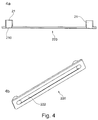
- FIG. 4 displays in detail the top confining part 220 of the test chamber 20 of Fig. 2 and 3 .
- the top confining part 220 comprises the reservoirs 21 and an elongated recess 222 along the longitudinal direction of the top confining part 220 extending between the reservoirs 21.
- the second part 202 acts as a bottom confining part and a rectangular cavity 221 is formed between the material sample 40 and the top confining part 220, which forms the fluid channel 22.
- Each of the reservoirs 21 is connected to the recess 222 through at least one opening 210.
- the transition region between the recess 222 and each of the reservoirs 21 around the opening 210 comprises rounded edges, which help preventing the formation of eddies in the blood sample when the rectangular cavity 221 acts as the fluid channel 22.
- the driving arrangement 30 was a rocking platform (Duomax 1030, Heidolph).
- the fluid channel 22 of the test chamber 20 had a rectangular cross-section and a top confining part 220 of silicone rubber.
- the receptacle 23 of the apparatus had a rectangular stripe-shape and the reservoirs 21 had rounded edges at the passage from the fluid channel 22 to the reservoirs 21 avoiding the formation of eddies in the blood sample.
- the longitudinal axis of the test chamber 20 was aligned with the rocking platform such that the tilting movement be in the direction of said longitudinal axis. Up to 8 test chambers 20 were simultaneously loaded onto the rocking platform.
- Substitute liquids were used in the preliminary assessment of the flowing conditions so as not to waste real blood for this purpose.
- a mixture of 35% glycerine (glycerol anhydrous, Applichem GmbH, Germany) and 65% saline solution was used to simulate whole blood, and distilled water was used to simulate platelet suspension.
- These fluids were chosen because the viscosity and density are similar to those of the corresponding true biological fluids.
- Their kinematic viscosity was measured with a capillary viscometer (Ubbelohde AVS 310, Schott-Gerate GmbH, Germany) and the density was measured with a density meter (DensityMeter DMA 4100M, Anton Paar GmbH, Austria).
- the glycerine solution and the distilled water were respectively pipetted into a 2-mm-high and a 1-mm-high fluid channel. Two different kinds of fluid channel were used due to the different viscosities of whole blood and the platelet suspension.
- the test chambers were placed on the rocking platform and this was configured to operate with a maximum tilt angle of 5°. By adding coloured fluid in one of the reservoirs, it was possible to visualise the velocity profile of the fluids for tilting frequencies varying between 2 and 50 rpm. The velocity of the fluid in the centre-line of the fluid channel ( v 0 ) was recorded over time.
- K 2 is another correction factor that adapts the amplitude of the periodic flow depending on the reciprocating frequency and is a function of the Womersley number.
- K 2 was calculated using the formula of Loudon and Tordesillas shown in The use of the dimensionless Womersley number to characterise the unsteady nature of internal flow. J. theor. Biol. 1998;191:63-78 . Assuming the ideal case of a Poiseuille flow between two plates, the constants K 1 and K 2 were taken to be 1. This assumption was found to be justified for tilting frequencies over 7.5 rpm.
- the main flow velocity of the test fluids over a tilting period corresponded to a sinus curve and the maximum amplitude v max obtained during a tilt movement was found to depend on the reciprocating frequency.
- the highest values of v max were 11.3 cm/s at 30 rpm for the glycerine solution in the 2-mm-high fluid channel and 6.3 cm/s at 10 rpm for distilled water in the 1-mm-high fluid channel.
- the inertia of the fluid limited a higher flow velocity.
- the measured density and viscosity of the test fluids were comparable to those of whole blood and platelet suspension so that the flow characteristics in the fluid channel should be approximately equivalent.
- the maximum Reynolds number was 120, which guarantees laminar flow conditions for all configurations and tilting velocities.
- the Wormersley number ⁇ was smaller than 1 for all configurations at 30 rpm, which guaranteed quasi-steady flow conditions for tilting frequencies up to 30 rpm.
- the obtained wall shear rate ⁇ for whole blood and the platelet suspension depending on the reciprocating frequency is represented in figure 5 . In both cases the shear rate increased with the reciprocating frequency up to a maximum value of 339 s -1 for whole blood and 380 s -1 for the platelet suspension.
- the flow conditions in the fluid channel corresponded to those characteristic of veins and arteries.
- the resulting overlying supernatant and buffy coat concentrating most of the white blood cells and platelets were separated and underwent a second centrifugation at 2250 g for 9 minutes. Then the supernatant was removed and the resulting concentrated platelet suspension was adjusted to a concentration of 600 ⁇ 10 3 platelets/ ⁇ l (PLT/ ⁇ l) using phosphate buffered saline.
- Planar material samples having the form of a stripe of low-density polyethylene (PE, type DOWLEXTM 2107GC, Dow Chemical Company, USA), polypropylene (PP, type PCGH10, Sabic, Saudi Arabia), polyoxymethylene (POM, type HOSTAFORM® MT24U01, Celanese Corporation, USA) and silicone (type SILPURAN® UR 9030/60, Wacker Chemie AG, Germany) were used.
- the material samples of those four polymers were cleaned with 70%-2-propanol and vacuum dried for a minimum of 12 hours.
- the surface of the material samples was characterised before conducting the hemocompatibility tests in order to compare the results with values from the literature.
- the contact angle with water was measured to examine the wetting properties of the material samples with respect to aqueous liquids (Device OCA 20, DataPhysiy Instruments GmbH, Germany). For each material, ten measurements were conducted immediately after wetting with 2 ⁇ l drops. Topology and roughness of the surfaces of the material samples were assessed with a confocal microscope ( ⁇ Surf, NanoFocus Ag, Germany).
- the material samples were introduced into the receptacle of the test chambers with 2-mm-high fluid channels, which were then preheated to 37°C.
- the test chambers were filled with 8 ml of whole blood and then placed on the rocking platform for 60 minutes to operate according to the flow parameters indicated above at a constant temperature of 37°C. After that, the incubated blood samples were removed from the test chambers and the cell concentration was immediately measured. Three measurements were made for each material sample.
- a reduction of the number of platelets in the blood after incubation is linked to thrombogenic events such as the adhesion of platelets on the surface of the material samples and the formation of platelet aggregates.
- thrombogenic events such as the adhesion of platelets on the surface of the material samples and the formation of platelet aggregates.
- each value was normalised with the mean value of the platelet count for all materials after testing.
- test chambers having 1-mm-high fluid channels filled with 4.5 ml of platelet suspension.
- blood platelets could adhere to the surface of the material samples.
- the platelet suspensions were removed from the test chambers and 5 ml of phosphate buffered saline heated to 37°C was pipetted into one reservoir, made to flow through the fluid channel and removed from the other reservoir. This guaranteed that all samples underwent exactly the same wash procedure and only the adhered platelets remained on the surface of the material samples.
- lysis buffer solution Sodium Citrate Tribasic Dihydrate 0.1 M, p-Nitrophenyl-Phosphat 5 mM, Triton X-100 1%, pH 5.4
- the chemicals for the lysis buffer were all purchased from Sigma-Aldrich Co. LLC, USA.
- the purpose of the lysis buffer is that of dissolving the adhered platelets and releasing the enzyme ACP (Acid Phosphatase) which reacts with p-Nitrophenyl-Phosphat resulting in a colour change.
- the colour change is proportional to the number of thrombocytes dissolved in the lysis buffer and may be measured by means of UV spectroscopy so as to quantify the amount of platelets adhered to the surfaces of the material samples.
- the reaction was stopped with 210 ⁇ l sodium hydroxide (NaOH 2 mol/L, Merck KGaA, Germany), and 170 ⁇ l of the solution was pipetted in a 96-wells microtiter plate.
- the photometric absorbance of 170 ⁇ l of the solution was measured at 405 nm with an ELISA reader (Multiscan FC, Type 357, Thermo Fisher Scientific AG, USA).
- ELISA reader Multiscan FC, Type 357, Thermo Fisher Scientific AG, USA.
- a standard curve was applied which was generated using a dilution series of platelet suspensions.
- test chambers were placed on a separate rocking platform configured to operate with a maximum tilt angle of 5° and a reciprocating frequency of 30 rpm.
- One test chamber was left under static conditions. The temperature was kept at 37°C and after 30 minutes, 60 minutes and 90 minutes, blood was collected from one of the dynamically incubated chambers. Blood from the statically incubated chamber was collected after 90 minutes.
- the amount of free haemoglobin in the obtained plasma of the blood samples was measured. For this purpose, the collected blood samples were centrifuged at 1000 g for 10 minutes. Plasma was drawn off and recentrifuged at 1000 g for another 10 minutes.
- Hemoglobin has three absorbance peaks at 451 nm, 541 mm and 577 nm. Because of the small amounts of hemoglobin in plasma, the quantification method described by Harboe in "A method for determination of hemoglobin in plasma by near-ultraviolet spectrophotometry. Scandinav. J. Clin. & Lab. Investigation 1959;11:66-70 " based on the analysis of the highest peak at 450 nm was chosen.
- the analysis of hematocrit measurements indicated a reduction of the number of platelets in the blood samples during incubation in the apparatus according to an embodiment of the invention. This can be due to platelet adhesion on the surface of the material sample and to activation or aggregation of platelets in the flowing blood samples.
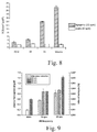
- Figure 6 shows the reduction in the number of platelets after contact with the four different kinds of material sample. The only significant difference in the platelet deprivation was found between PP and silicone, were silicone was the material with the least depraved platelets and PP the one which caused the highest platelet deprivation, 37% more platelet reduction than on silicone. The results showed significant differences for most of the test materials.
- the amount of detected platelets per mm 2 surface area (PLT/ mm 2 ) of material sample varied between 17,000 PLT/ mm 2 for silicone and 4000 PLT/ mm 2 for POM.
- PP and PE have intermediate amounts of adhered platelets on their surface with respectively 6000 PLT/ mm 2 and 12000 PLT/ mm 2 .
- the most platelets were found on the silicone material sample and they exhibited an advanced stage of adhesion with spreading of pseudopodia and formation of platelet aggregates. No aggregates were found on the material samples of PE, PP and POM, and the cells were observed to be isolated and dispersed on the surface. More platelets were found on PE than on PP and in both cases they were strongly activated and spread numerous pseudopodia. A smaller amount of platelets was found on POM and they were less activated than on other materials.
- Figure 8 shows the difference in the platelet adhesion when the same cell suspension is simultaneously incubated under static (0 rpm) or dynamic (15 rpm) flow conditions. Very few platelets were detected after incubation under static flow conditions and variations between the different test materials were minimal, from 1660 PLT/ mm 2 for silicone to 2020 PLT/ mm 2 for PP. However, after incubation the amount of adhered platelets increased greatly and pronounced differences between the different test materials could be measured, from 2800 PLT/ mm 2 for POM to 21,700 PLT/ mm 2 for silicone. This confirms that the detection of platelets was absolutely caused by the flow-induced adhesion of the platelets on the surface of the material samples and excludes the possibility that the detected platelets came from residual blood which may not have been removed by the washing procedure.
- the levels of plasma hemoglobin detected after incubation of the blood samples in the test chambers and the corresponding index of hemolysis are shown in Fig. 9 .
- the amount of free hemoglobin in plasma was 0.2 mg/dl and after 90 minutes static incubation in the apparatus, the amount of plasma hemoglobin was 0.6 mg/dl. The difference between the two values was presumably due to the blood damage by pipetting.
- the amount of plasma hemoglobin for the dynamically incubated blood samples ranged between 0.5 and 1.5 mg/dl, which is still in the lower range of free hemoglobin in blood plasma for healthy subjects (0 mg/dl to 10 mg/dl).
- Hemoglobin release in plasma was slightly elevated by high shear rates (340 s -1 at 30 rpm, arterial flow conditions) with respect to low shear rates (135 s -1 at 10 rpm, venous flow conditions). A time dependence of the hemoglobin release could also be observed and the maximum plasma hemoglobin (1.42 mg/dl) was reached after 90 minutes at 30 rpm.
Abstract
Disclosed is an apparatus 10 for testing blood interaction properties, of a material sample 40, in particular regarding hemocompatibility. The apparatus comprises at least one test chamber 20 for receiving a blood sample comprising at least two reservoirs 21, a fluid channel 22 extending between the at least two reservoirs 21, and a receptacle for receiving the material sample 40. The receptacle is arranged with respect to the fluid channel 22 such that when the blood sample is received in the test chamber 10 and the material sample 40 is received in the receptacle, the blood sample flowing in the fluid channel 22 may flow in contact with the material sample 40. The apparatus further comprises a driving arrangement 30. The driving arrangement 30 is configured for providing a reciprocating movement of the at least one test chamber 20 or parts thereof such as to alternatingly raise one of the reservoirs 21 with respect to the other, thereby causing the blood sample in the fluid channel 22 to flow back and forth from one reservoir to the other.
Description
- The present invention is in the field of biomedical technology. In particular, the present invention relates to the dynamic evaluation of the hemocompatibility of materials.
- The evaluation of blood interaction properties, in particular of hemocompatibility, of materials employed in the fabrication of biomedical devices such as implants, stents, drug delivery systems and cardiopulmonary bypasses requires the use of blood incubation systems which simulate physiological flow conditions as realistically as possible. In the design and development of such biomedical devices it is of uppermost importance to predict any possible interactions and complications, which might occur once the device is in contact with blood, like thrombosis, coagulation, protein absorption, or hemolysis complement system activation.
- Regarding hemocompatibility, the conditions under which such blood interaction properties tests must be carried out are regulated by the DIN EN ISO 10993-4 norm, which recommends the use of dynamic evaluations, which reproduce better the real physiological flow conditions inside the body. However, the norm does not describe a particular test bench with which the tests should be carried out. Several kinds of testing systems are available. Most of the currently available systems for dynamic evaluation of hemocompatibility have serious limitations, especially regarding restricted ability to change the tested materials and poor access to the test surface of the same. Further problems include the unwanted influencing of the results of the experiment due to damage of blood cells during the test.
- In view of the necessity of the reproducibility of the experiments and the comparability between different test samples, the use of simple geometries for the sample materials whose blood interaction properties are to be tested is preferable.
- Given the limitations of the currently available testing systems, there is room for technical improvements in the dynamic evaluation of blood interaction properties. A testing system overcoming the deficiencies of most current systems could furthermore pave the way to standardised testing, like for example for dynamic hemocompatibility testing in the DIN norm.
-
US 2011/0045993 discloses a microfluidic device for testing the interaction between a fluid sample and a test material comprising a sample inlet, a sample outlet and a flow cavity extending between the sample inlet and the sample outlet for flow of a fluid sample through the flow cavity. The flow cavity comprises a test area to which at least one test material can be attached. When the fluid sample is made to flow through the flow cavity, a shear force between the test area and the fluid sample flowing over the test area is substantially constant. -
US 2014/0287451 describes a flow chamber having an inlet port, an exit port and a flow channel extending between the inlet port and the exit port. The fluid channel is configured to hold a sample so that a fluid flowing from the inlet port to the exit port through the flow chamber contacts a side of the sample. The test chamber further has an optically transparent viewing window adjacent to the flow channel so that the sample can be observed in real-time while it is exposed to the fluid. - The problem underlying the invention is to provide means and a method for dynamically testing blood interaction properties of a sample material with reduced damage of blood cells during the test and the possibility to easily change the sample material. This problem is solved by an apparatus according to
claim 1 and a method according toclaim 10. - The apparatus of the invention comprises at least one test chamber for receiving a blood sample. Herein, the term "blood sample" is understood to have a broad meaning and covers any liquid substance comprising at least parts of human or animal blood.
- The test chamber comprises at least two reservoirs, a fluid channel extending between the at least two reservoirs and a receptacle for receiving the material sample. The receptacle might for example be any geometric configuration allowing for the arrangement of the material sample in the test chamber, like but not restricted to, an indent or a depression. The receptacle is arranged with respect to the fluid channel such that when the blood sample is received in the test chamber and the material sample is received in the receptacle, the blood sample flowing in the fluid channel may flow in contact with the material sample. Note that the term "test chamber" has been chosen to indicate that the reservoirs and the fluid channel form a hollow structure for accommodating the blood sample, but shall not imply any further structural limitations. In particular, it does not imply that the reservoirs and the fluid channel are necessarily rigidly connected. Instead, the reservoirs and the fluid channel could for example be connected by flexible tubes or the like.
- The apparatus further comprises a driving arrangement configured for providing a reciprocating movement of at least a part of the at least one test chamber such as to alternatingly raise one of the reservoirs with respect to the other, thereby causing the blood sample in the fluid channel to flow back and forth from one reservoir to the other. Herein, the driving arrangement can be any type of mechanical, magnetic, electric or electronic system or any combination thereof suitable for providing the reciprocating movement of the test chambers or parts thereof.
- According to the invention, the reciprocating movement of the test chamber provided by the driving arrangement alternatingly raises one of the reservoirs with respect to the other such that gravity causes the blood sample in the fluid channel to flow in contact with the material sample alternatingly from the momentarily higher reservoir to the momentarily lower reservoir. This way the blood sample interacts dynamically with the material sample, thereby simulating the physiological conditions inside true blood vessels. This allows for the dynamic evaluation of blood interaction properties without the use of a pump to drive the blood sample flow, which significantly reduces the damage to blood cells in the course of the test of blood interaction properties and hence the influence of the testing system itself over the results of the test. As will be shown in the examples below, this advantageous feature is confirmed by experimental results showing that the invention induces upon the blood sample a much lower release of free hemoglobin in plasma than standard testing setups. Hereby a major deficiency of most known experimental setups for dynamic hemocompatibility testing, which are based in the use of pumps for driving the blood flow, is overcome.
- Additionally, by not using a pump the necessity of removing the air from the test chambers prior to incubation, which could induce a waste of blood, is eliminated. This introduces a clear advantage with respect to known test systems for dynamic hemocompatibility testing based on the use of tubes, like the standard "Chandler loop".
- Both reservoirs typically have the same form and volume. The reservoirs might have a cylindrical form, although other geometries are possible. The reservoirs may be connected to the fluid channel through at least one opening. In addition, the reservoirs may be open at their upper end so as to allow the fluid to flow in the fluid channel freely under the influence of gravity without any restriction due to a pressure gradient in the test chamber.
- Preferably, the amount of the blood sample in the test chamber is chosen such that the volume of the blood sample is bigger than the added volume of the fluid channel and of one of the reservoirs and smaller than the added volume of the fluid channel and of both reservoirs. This way, at any stage of the reciprocating movement of the test chamber, the fluid channel is completely filled with the blood sample, while the excess volume of the blood sample not fitting in the fluid channel partially fills the reservoirs. When both reservoirs have the same volume and one of the reservoirs is raised with respect to the other, a larger amount of the blood sample accumulates in the reservoir momentarily having the lower position. When both reservoirs are arranged equally high, both reservoirs are partially filled with the same amount of the blood sample. The volume of the reservoirs is preferably big enough so as to guarantee that no blood sample flows out of the test chamber during the operation of the apparatus. Other arrangements regarding the volume of the blood sample, the fluid channel and the reservoirs are possible, so as to enable different flowing configurations.
- According to a preferred embodiment of the invention, the driving arrangement comprises a rocking platform or a rocker that provides a reciprocating tilting movement of the at least one test chamber. The at least one test chamber is then placed or arranged on the platform of the rocking platform. The adjustment of the frequency and maximum angle of the reciprocating tilting movement of the test chamber driven by the rocking platform allows for an easy and direct control of the parameters determining the flow conditions of the blood sample in the test chamber, such as the flow rate or the wall shear rate.
- The reciprocating tilting movement of the test chamber driven by the driving arrangement is typically a tilting of the test chamber with respect to a horizontal rest position, wherein the tilting movement takes place in a vertical plane. This vertical plane preferably contains the direction corresponding to the longitudinal direction of the test chamber. Preferably, the longitudinal direction of the test chamber and the longitudinal direction of the fluid channel coincide, such that the instant axis of rotation of the tilting movement of the test chamber is perpendicular to the longitudinal direction of the fluid channel. As a consequence of that, as will be evident to the skilled person, a fluid flow inside the fluid channel only occurs along the longitudinal direction of the fluid channel. However, other configurations might be used.
- In a preferred embodiment of the invention, the at least one test chamber comprises a first part and a second part, which are releasably secured to one another, for example by means of screws or other means for pressing the parts together. In addition, means may be provided for fixing the at least one test chamber to the driving arrangement. By releasing either of the parts, access to the receptacle is obtained, which allows the material sample to be easily placed, exchanged or removed. This facilitates the investigation of a broader range of sample materials while keeping the assembly of the apparatus parts simple, thereby minimising the risk of operating errors and reducing operation time. Furthermore, the simple structure of the test chamber renders its fabrication technically easier and hence less costly and its operation more accessible and intuitive. In addition, easy access to the inner space of the test chamber makes it possible to analyse the properties of the surface of the same before its contact with the blood sample as well as the changes caused by the interaction with the blood sample after interaction.
- According to a preferred embodiment of the invention, the receptacle is configured for receiving a planar material sample. The planar geometry of the receptacle allows for an easy operation of the apparatus when it comes to placing, exchanging or removing the material sample and reduces the time needed for preparation or manipulation of the apparatus. It further provides easy and direct access to the test surface of the material sample, both before and after it has interacted with the blood sample in the apparatus and hence facilitates the investigation of said test surface. Herein, "test surface" refers to the surface of the material sample facing the inside of the fluid channel. This enables for example the detailed characterization of the chemical composition, the structure, the coating or the roughness of the test surface of the material sample before its contact with the blood sample. It further allows investigation of the blood components adhered to the test surface after the material sample and the blood sample have interacted in the apparatus.
- In a preferred embodiment of invention, the planar material sample to be received in the receptacle has the form of a stripe. Herein a stripe is understood as having a generally rectangular shape with one of its dimensions significantly longer than the other one, for example at least three times longer. This allows for the use of planar material samples with standardized geometry, dimensions and structure, thereby offering a better control over the universe of possible test objects for analysis and comparison. In addition, such a stripe-like shape contributes to the reduction of the influence of the apparatus upon the results of testing by allowing for a very reproducible washing procedure of the material samples. Washing steps are commonly employed in the course of testing and in previously known testing systems they are typically performed by pipetting a wash solution on the sample, which may lead to uncontrolled detachment of adhered cells from the surface of the material sample due to strong shear stress and hence to uncontrolled changes in the cell concentrations on the surface of the material sample.
- According to a preferred embodiment of the invention, the at least one test chamber comprises a top confining part and a bottom confining part, wherein the top confining part and the bottom confining part can be tightly and releasably secured to one another and the receptacle is arranged within the bottom confining part, such that when the material sample is received in the receptacle and the top confining part and the bottom confining part are tightly secured to one another, a cavity between the top confining part and the material sample is formed that acts as the fluid channel. The top confining part of the test chamber is preferably made of silicone rubber, although other material compositions are possible. The bottom confining part may be formed by the second part of the at least one test chamber. According to this embodiment, when the blood sample is introduced into the test chamber and made to flow in the fluid channel, the blood sample flows between top confining part of the test chamber and the material sample. This configuration reduces the contact of the blood sample with surfaces not to be tested, which for example suppresses unwanted blood activation and uncontrolled interactions. This preferred embodiment further allows for configurations in which, provided a suitable amount of the blood sample is filled into the test chamber, the material sample that constitutes the bottom part of the fluid channel is entirely covered with the blood sample and hence is not in contact with air during the blood interaction properties test, thereby eliminating possible uncontrolled effects that could be caused by the interaction with air.
- In a preferred embodiment of the invention, the apparatus further comprises a transition region between the fluid channel and each of the reservoirs, said transition region comprising rounded edges to prevent or at least reduce the formation of eddies in the blood sample flow in said transition region. The prevention or reduction of the formation of eddies in the blood sample contributes to avoid unwanted blood activation like clotting, a better control of the testing conditions and the flow parameters and allows for testing the material sample under conditions that better reproduce physiological flow conditions.
- According to a preferred embodiment of the invention, the driving arrangement is adapted for simultaneously providing the reciprocating tilting movement of at least two, preferably of at least four and most preferably of at least six test chambers. This makes it possible to test several material samples simultaneously thereby reducing the time required for testing different material samples. In the case that the driving arrangement is a rocking platform, at least some of the test chambers might be stapled on top of each other on the platform of the rocking platform and optionally secured thereto. This does not only increase the throughput of the test, but may also increase its reproducibility and significance by making it possible to obtain identically obtained blood samples and material samples simultaneously subjected to evaluation under the same testing conditions, thereby reducing the need of any waiting time that may influence the test results in an uncontrolled manner or render the repetition of experiments necessary.
- Regarding the volume of the blood sample, a compromise should be found between volumes of blood sample sufficient for performing the analysis and avoiding a waste of blood, which is in general a limited resource for experimental purposes. Accordingly, in a preferred embodiment of the invention, the fluid channel has a volume between 2.5 cm3 and 20 cm3, preferably between 3.0 cm3 and 12 cm3, and most preferably between 4.5 cm3 and 8 cm3.
- In a preferred embodiment, the fluid channel has a rectangular cross-section. This geometry of the fluid channel makes it possible to approximately resemble physiological flow conditions inside blood vessels while preserving the ability to easily change the material sample and the direct access to the receptacle, the material sample and the test surface of the latter.
- According to a preferred embodiment of the invention, the cross-section of the fluid channel has a width to height ratio between 1 and 40, preferably between 10 and 30 and most preferably between 15 and 25. Preferably, the fluid channel has a cross-section between 10 mm2 and 30 mm2. This has the advantage of maximising the contact surface of the material sample with respect to a given cross-section of the fluid flow.
- A further aspect of the invention relates to a method for evaluating blood interaction properties of a material sample comprising the steps of:
- a) providing a material sample and inserting the material sample into the receptacle of an apparatus for testing blood interaction properties of a material sample according to any of the embodiments described above;
- b) filling a blood sample into the at least one test chamber;
- c) operating the driving arrangement for providing a reciprocating movement of the at least one test chamber such as to alternatingly raise one of the reservoirs with respect to the other, thereby causing the blood sample in the fluid channel to flow back and forth from one reservoir to the other in direct contact with the material sample; and
- d) performing an analysis of one or both of the material sample and the blood sample after the material sample and the blood sample have interacted in the apparatus.
- In a preferred embodiment of the invention, the step of providing a material sample comprises preheating the material sample to a temperature between 35°C and 42°C, preferably between 36°C and 38°C, so as to reproduce physiological conditions.
- In another preferred embodiment of the invention, the method may further comprise, prior to step b), a step for preparing the blood sample. This may for example comprise mixing blood with an anticoagulant or preparing a blood sample with a predefined cell concentration so as to minimise the donor-dependent factor influencing the result of the evaluation. This temperature is preferably maintained during the blood interaction properties evaluation procedure.
- According to a preferred embodiment of the invention, the method may further comprise, prior to step b), a step of measuring of properties of the blood sample before interaction with the material sample in the apparatus. In particular this may comprise measuring a cell concentration of the blood sample.
- Step c) of operating the driving arrangement may comprise configuring it to provide the reciprocating movement of the at least one test chamber according to predefined parameters, like for example reciprocating frequency, maximum height of the reservoirs or operation time. Said parameters might be constant or variable in time. Herein, the reciprocating frequency refers to the rate at which each of the reservoirs alternatingly occupies the highest attainable position with respect to a horizontal rest position and may be measured in revolutions per minute (rpm) according to the number of times one of the reservoirs successively occupies the highest position in a period of time of one minute. The maximum height refers to the maximum height with respect to a horizontal rest position.
- In the case that the driving arrangement is a rocking platform, the parameters determining the flow conditions of the blood sample in the fluid channel might be the reciprocating frequency and the maximum tilt angle. Herein the maximum tilt angle refers to the maximum tilt angle of the at least one test chamber with respect to the horizontal rest position, that is the angle between the longitudinal axis of the test chamber and the horizontal rest position when one of the reservoirs has achieved the highest attainable position.
- The choice of the reciprocating frequency and the maximum height of the reservoirs or the maximum tilt angle should be such that the resulting flowing conditions of the blood sample in the fluid channel at least approximately resemble physiological conditions. The concrete correlation between reciprocating frequency and maximum height of the reservoirs or maximum tilt angle on the one side and flowing conditions of the blood sample on the other side can be calculated from the corresponding fluid mechanics equations, as will be shown in the examples below. According to this requirement, in a preferred embodiment of the invention, step c) of operating the driving arrangement may comprise configuring said driving arrangement to provide the reciprocating tilting movement of the at least one test chamber with a reciprocating frequency between 2 and 50 rpm and a maximum tilt angle between 1 and 20 degrees or a maximum height of the reservoirs that corresponds to such maximum tilt angle.
- According to a preferred embodiment of the invention, step c) of operating the driving arrangement may comprise configuring said driving arrangement to operate for a period of time between 1 and 240 minutes, preferably between 60 and 90 minutes. This has been experimentally determined to be long enough for the interaction of the blood sample with the material sample to have measureable consequences and hence to ensure good simulation of the in-vivo application of the material sample.
- According to various embodiments of the invention, step d) of performing an analysis of one or both of the material sample and the blood sample after the material sample and the blood sample have interacted in the apparatus may comprise any kind of analysis aiming at characterizing the blood interaction properties of the tested material. In particular, said step may comprise one or more of
- a platelet adhesion test to measure the density of platelets adhered to the material sample during incubation;
- a scanning electron microscopy analysis of the material samples to recognize platelets adhered to the material sample during incubation;
- a platelet deprivation test of the blood sample to measure changes in the platelet concentration of the blood sample during incubation.
- a hemolysis test of the blood sample to measure the hemolysis caused during incubation;
-
- Fig. 1
- shows a schematic representation of an apparatus according to an embodiment of the invention comprising a test chamber and a driving arrangement.
- Fig. 2
- is an exploded view of the components of the test chamber of
Fig. 1 . - Fig. 3
- shows in detail the test chamber of
Fig. 1 and2 .- a) is a sectional view of the test chamber of
Fig. 1 and2 . - b) shows a perspective view of the test chamber of
Fig. 1 and2 .
- a) is a sectional view of the test chamber of
- Fig. 4
- shows in detail the top confining part of the test chamber of
Fig. 2 and3 .- a) is a base view of the top confining part of
Fig. 2 and3 . - b) is a perspective bottom view of the top confining part of
Fig. 2 and3 .
Fig. 1 depending on the reciprocating frequency.
Fig. 6 displays the platelet deprivation in whole blood after 60 minutes incubation in the apparatus ofFig. 1 at a reciprocating frequency of 30 rpm of four different test materials.
Fig. 7 displays the platelet adhesion on the surfaces of four different test materials of a platelet suspension after 60 minutes incubation in the apparatus ofFig. 1 at a reciprocating frequency of 15 rpm.
Fig. 8 displays a comparison of the platelet adhesion on the surfaces of four different test materials after 60 minutes incubation in the apparatus ofFig. 1 under static conditions and dynamic flow conditions with a tilting frequency of 15 rpm.
Fig. 9 displays the measured quantity of free hemoglobin in blood plasma and the index of hemolysis experienced by whole blood after 30, 60 and 90 minutes incubation in the apparatus ofFig. 1 with tilting frequencies of 10 rpm and 30 rpm and the corresponding values of a statically incubated blood sample right after blood collection and after 90 minutes incubation. - a) is a base view of the top confining part of
- For the purposes of promoting an understanding of the principles of the invention, reference will now be made to a preferred embodiment illustrated in the drawings, and specific language will be used to describe the same. It will nevertheless be understood that no limitation of the scope of the invention is thereby intended, such alterations and further modifications in the illustrated apparatus and such further applications of the principles of the invention as illustrated therein being contemplated as would normally occur now or in the future to one skilled in the art to which the invention relates.
-
Figure 1 shows a schematic representation of anapparatus 10 for testing blood interaction properties of a material sample according to a preferred embodiment of the invention. Theapparatus 10 comprises atest chamber 20 for receiving a blood sample and a drivingarrangement 30. Thetest chamber 20 comprises tworeservoirs 21, afluid channel 22 extending between the tworeservoirs 21, and a receptacle 23 (seeFig. 2 and3 ) for receiving a material sample, not shown inFig. 1 . Thereceptacle 23 is arranged with respect to thefluid channel 22 in such a way that when the blood sample is received in thetest chamber 20 and thereceptacle 23 receives the material sample, the blood sample flowing in thefluid channel 22 may flow in contact with the material sample. The drivingarrangement 30 is configured for providing a reciprocating movement of thetest chamber 20 such as to alternatingly raise one of thereservoirs 21 with respect to the other, so that gravity causes the blood sample in thefluid channel 22 to flow in contact with the material sample in thereceptacle 23 alternatingly from the momentarily higher reservoir to the momentarily lower reservoir. - The driving
arrangement 30 can generally be any type of mechanical, magnetic, electric or electronic system or any combination thereof suitable for providing the reciprocating movement of thetest chamber 20. InFig. 1 , the drivingarrangement 30 is symbolically represented by a triangle, which stands for any suitable arrangement, which in this particular case, comprises aplatform 31 on which thetest chamber 20 is placed and provides a reciprocating tilting movement of thetest chamber 20. In particular, the drivingarrangement 30 might be a rocking platform or rocker comprising a platform on which several test chambers can be placed for being simultaneously driven. - Both
reservoirs 21 have the same cylindrical shape and identical volume. Thereservoirs 21 are connected to thefluid channel 22 through at least oneopening 210. The transition region between thefluid channel 22 and each of thereservoirs 21 around theopening 210 comprises rounded edges, not shown inFig. 1 (seeFig. 4 ), to prevent or at least to reduce the formation of eddies in a blood sample flowing in said transition region. In addition, thereservoirs 21 have asecond opening 212 to establish atmospheric pressure in thereservoirs 21, thereby allowing the fluid in thefluid channel 22 to flow freely under the influence of gravity. - In the embodiment shown, the amount of the blood sample in the
test chamber 20 is chosen such that the volume of the blood sample is bigger than the added volume of thefluid channel 22 and of one of thereservoirs 21 and smaller than the added volume of thefluid channel 22 and of bothreservoirs 21. This way, at any stage of the reciprocating tilting movement of thetest chamber 20, thefluid channel 22 is completely filled with the blood sample, while the excess volume of the blood sample not fitting in the fluid channel partially fills thereservoirs 21. When the tilt angle of thetest chamber 20 is different from 0, like in the top and the bottom situation displayed inFig. 1 , a bigger amount of the blood sample accumulates in the reservoir momentarily having the lower position. When the tilt angle of thetest chamber 20 is zero, as is the case in the middle situation displayed inFig. 1 , thetest chamber 20 momentarily is arranged horizontally and bothreservoirs 21 are partially filled with the same amount of the blood sample. In the present embodiment, thefluid channel 22 has a rectangular cross-section with a width to height ratio of 14 and a volume of 4,5 cm3. -
Figure 2 shows an exploded view of the components of thetest chamber 20 ofFig. 1 . Thetest chamber 20 comprises afirst part 201, a top confiningpart 220 of thefluid channel 22 and asecond part 202 confining thefluid channel 22. Thesecond part 202 comprises thereceptacle 23 for receiving amaterial sample 40. Between thefirst part 201 and thesecond part 202 of thetest chamber 20, thetop confining part 220 of thefluid channel 22 is arranged, such that when thefirst part 201 and thesecond part 202 are secured to one another by means ofscrews 203, thetop confining part 220 of thefluid channel 22 is clamped into thereceptacle 23. The base of thereceptacle 23 in thesecond part 202 then constitutes a bottom confining part of thefluid channel 22, and arectangular cavity 221, not seen in the exploded view ofFig. 2 is formed between the top confiningpart 220 of thefluid channel 22 and thesecond part 202, which constitutes thefluid channel 22. In particular, when amaterial sample 40 is received in thereceptacle 23, a fluid flowing in therectangular cavity 221 flows in contact with saidmaterial sample 40. As displayed inFig. 2 , thematerial sample 40 received in thereceptacle 23 has the form of a stripe. Thematerial sample 40 can be tightly secured to thetop confining part 220 of thefluid channel 22 by securing together thefirst part 201 and thesecond part 202 of thetest chamber 20, within which thetop confining part 220 of thefluid channel 22 is arranged. Thematerial sample 40 then entirely covers thereceptacle 23, so that it forms the bottom of thefluid channel 22. Thetop confining part 220 of thefluid channel 22 is made of silicone rubber. -
Figure 3 shows a cross-sectioned and a perspective view of thetest chamber 20 ofFig. 1 and2 . Here, thescrews 203 are holding together thefirst part 201 and thesecond part 202 of thetest chamber 20. Thetop confining part 220 is arranged within thefirst part 201 and thesecond part 202. Thematerial sample 40 is received in thereceptacle 23 arranged within thesecond part 202. FurtherFig. 3 depicts arectangular cavity 221, which is formed between the top confiningpart 220 and thematerial sample 40 through which the blood sample may flow, and which constitutes thefluid channel 22. -
Figure 4 displays in detail thetop confining part 220 of thetest chamber 20 ofFig. 2 and3 . Thetop confining part 220 comprises thereservoirs 21 and anelongated recess 222 along the longitudinal direction of the top confiningpart 220 extending between thereservoirs 21. When the top confiningpart 220 is arranged between thematerial sample 40 and thefirst part 201 in the way shown inFig. 2 and3 , and thefirst part 201 is secured to thesecond part 202, thesecond part 202 acts as a bottom confining part and arectangular cavity 221 is formed between thematerial sample 40 and thetop confining part 220, which forms thefluid channel 22. Each of thereservoirs 21 is connected to therecess 222 through at least oneopening 210. The transition region between therecess 222 and each of thereservoirs 21 around theopening 210 comprises rounded edges, which help preventing the formation of eddies in the blood sample when therectangular cavity 221 acts as thefluid channel 22. - In order to test the suitability of an apparatus and methods according to embodiments of the invention for testing blood interaction properties of a material sample and to compare their performance to that of other testing systems known from the prior art, hemocompatibility of four common polymeric materials was investigated using such apparatus and methods.
- A preliminary assessment of the flowing conditions of the blood samples in the fluid channel based on an experimental survey of the corresponding flow parameters was followed by the preparation of the blood samples and material samples. These were disposed in the apparatus and subsequently subjected to the methods according to various embodiments of the invention.
- The obtained results confirm the suitability of the apparatus and methods according to an embodiment of the invention for dynamically testing blood interaction properties and highlight the improvements over previously known testing systems.
- An
apparatus 10 as shown inFig. 1 to 3 was used. The drivingarrangement 30 was a rocking platform (Duomax 1030, Heidolph). Thefluid channel 22 of thetest chamber 20 had a rectangular cross-section and a top confiningpart 220 of silicone rubber. The dimensions of thefluid channel 22 were: width = 14 mm, length = 218 mm, height = 1 mm or 2 mm. Thereservoirs 21 had cylindrical shape and the dimensions were: diameter = 17 mm and height = 20 mm. Thereceptacle 23 of the apparatus had a rectangular stripe-shape and thereservoirs 21 had rounded edges at the passage from thefluid channel 22 to thereservoirs 21 avoiding the formation of eddies in the blood sample. The longitudinal axis of thetest chamber 20 was aligned with the rocking platform such that the tilting movement be in the direction of said longitudinal axis. Up to 8test chambers 20 were simultaneously loaded onto the rocking platform. - Substitute liquids were used in the preliminary assessment of the flowing conditions so as not to waste real blood for this purpose. A mixture of 35% glycerine (glycerol anhydrous, Applichem GmbH, Germany) and 65% saline solution was used to simulate whole blood, and distilled water was used to simulate platelet suspension. These fluids were chosen because the viscosity and density are similar to those of the corresponding true biological fluids. Their kinematic viscosity was measured with a capillary viscometer (Ubbelohde AVS 310, Schott-Gerate GmbH, Germany) and the density was measured with a density meter (DensityMeter DMA 4100M, Anton Paar GmbH, Austria).
- The glycerine solution and the distilled water were respectively pipetted into a 2-mm-high and a 1-mm-high fluid channel. Two different kinds of fluid channel were used due to the different viscosities of whole blood and the platelet suspension. The test chambers were placed on the rocking platform and this was configured to operate with a maximum tilt angle of 5°. By adding coloured fluid in one of the reservoirs, it was possible to visualise the velocity profile of the fluids for tilting frequencies varying between 2 and 50 rpm. The velocity of the fluid in the centre-line of the fluid channel (v 0) was recorded over time. The flow rate in the fluid channel Q was calculated using

v is the mean velocity of the fluid over the cross section of the fluid channel. The mean velocity can be calculated from the velocity in the centre-line using

- The main flow velocity of the test fluids over a tilting period corresponded to a sinus curve and the maximum amplitude
v max obtained during a tilt movement was found to depend on the reciprocating frequency. The highest values ofv max were 11.3 cm/s at 30 rpm for the glycerine solution in the 2-mm-high fluid channel and 6.3 cm/s at 10 rpm for distilled water in the 1-mm-high fluid channel. For higher tilting velocities, the inertia of the fluid limited a higher flow velocity. The measured density and viscosity of the test fluids were comparable to those of whole blood and platelet suspension so that the flow characteristics in the fluid channel should be approximately equivalent. The maximum Reynolds number was 120, which guarantees laminar flow conditions for all configurations and tilting velocities. The Wormersley number α was smaller than 1 for all configurations at 30 rpm, which guaranteed quasi-steady flow conditions for tilting frequencies up to 30 rpm. The obtained wall shear rate γ for whole blood and the platelet suspension depending on the reciprocating frequency is represented infigure 5 . In both cases the shear rate increased with the reciprocating frequency up to a maximum value of 339 s-1 for whole blood and 380 s-1 for the platelet suspension. In view of the values of the shear rates reached in the fluid channel of the tested apparatus, the flow conditions in the fluid channel corresponded to those characteristic of veins and arteries. By adjusting the reciprocating frequency depending on the geometry of the fluid channel, it was possible to conduct the experiment under varying well-defined flow conditions resembling those in true blood vessels. This shows that the apparatus according to an embodiment of the invention is suitable for hemocompatibility testing in flow conditions which are comparable to the physiological flow in blood vessels - Different tests were carried out using true blood samples formed by a platelet suspension or by whole blood. Human blood was obtained from healthy and voluntary donors and mixed with an anticoagulant, this being citrate (Vacuatte® ACD-A tubes, 9 ml, Greiner Bio-One International GmbH, Germany) in the tests with platelet suspensions and heparin (Vacuette® Lithium Heparin tube 9 ml, Greiner Bio-One International GmbH, Germany) in the tests with whole blood. Immediately after the blood withdrawal, the cell concentration was measured with a hematology analyser (KX-21N, Sysmex Europe GmbH, Germany). For the preparation of the platelet suspensions, the freshly collected blood was centrifuged at 1750 g for 6 minutes. The resulting overlying supernatant and buffy coat concentrating most of the white blood cells and platelets were separated and underwent a second centrifugation at 2250 g for 9 minutes. Then the supernatant was removed and the resulting concentrated platelet suspension was adjusted to a concentration of 600×103 platelets/µl (PLT/µl) using phosphate buffered saline.
- Planar material samples having the form of a stripe of low-density polyethylene (PE, type DOWLEX™ 2107GC, Dow Chemical Company, USA), polypropylene (PP, type PCGH10, Sabic, Saudi Arabia), polyoxymethylene (POM, type HOSTAFORM® MT24U01, Celanese Corporation, USA) and silicone (type SILPURAN® UR 9030/60, Wacker Chemie AG, Germany) were used. The material samples of those four polymers were cleaned with 70%-2-propanol and vacuum dried for a minimum of 12 hours. The surface of the material samples was characterised before conducting the hemocompatibility tests in order to compare the results with values from the literature. The contact angle with water was measured to examine the wetting properties of the material samples with respect to aqueous liquids (
Device OCA 20, DataPhysiy Instruments GmbH, Germany). For each material, ten measurements were conducted immediately after wetting with 2 µl drops. Topology and roughness of the surfaces of the material samples were assessed with a confocal microscope (µSurf, NanoFocus Ag, Germany). - The material samples were introduced into the receptacle of the test chambers with 2-mm-high fluid channels, which were then preheated to 37°C. The test chambers were filled with 8 ml of whole blood and then placed on the rocking platform for 60 minutes to operate according to the flow parameters indicated above at a constant temperature of 37°C. After that, the incubated blood samples were removed from the test chambers and the cell concentration was immediately measured. Three measurements were made for each material sample.
- A reduction of the number of platelets in the blood after incubation is linked to thrombogenic events such as the adhesion of platelets on the surface of the material samples and the formation of platelet aggregates. In view of the blood donor dependent variability of platelet number and function, each value was normalised with the mean value of the platelet count for all materials after testing.
- The same procedure was conducted with test chambers having 1-mm-high fluid channels filled with 4.5 ml of platelet suspension. During the 60 minutes incubation step, blood platelets could adhere to the surface of the material samples. After incubation, the platelet suspensions were removed from the test chambers and 5 ml of phosphate buffered saline heated to 37°C was pipetted into one reservoir, made to flow through the fluid channel and removed from the other reservoir. This guaranteed that all samples underwent exactly the same wash procedure and only the adhered platelets remained on the surface of the material samples. Then the material samples were removed from the test chambers and three fragments (
diameter 12 mm) of each stripe were stamped and placed in a microtiter plate with 300 µl lysis buffer solution (Sodium Citrate Tribasic Dihydrate 0.1 M, p-Nitrophenyl-Phosphat 5 mM, Triton X-100 1%, pH 5.4) for 1 hour at 37°C. The chemicals for the lysis buffer were all purchased from Sigma-Aldrich Co. LLC, USA. The purpose of the lysis buffer is that of dissolving the adhered platelets and releasing the enzyme ACP (Acid Phosphatase) which reacts with p-Nitrophenyl-Phosphat resulting in a colour change. The colour change is proportional to the number of thrombocytes dissolved in the lysis buffer and may be measured by means of UV spectroscopy so as to quantify the amount of platelets adhered to the surfaces of the material samples. After incubation, the reaction was stopped with 210 µl sodium hydroxide (NaOH 2 mol/L, Merck KGaA, Germany), and 170 µl of the solution was pipetted in a 96-wells microtiter plate. The photometric absorbance of 170 µl of the solution was measured at 405 nm with an ELISA reader (Multiscan FC, Type 357, Thermo Fisher Scientific AG, USA). In order to convert the absorbance values into the number of adhered platelets per square millimetre (PLT/mm2), a standard curve was applied which was generated using a dilution series of platelet suspensions. - The damage caused to red blood cells during testing was assessed with the quantification of the release of free hemoglobin in plasma of the blood samples consisting in whole blood induced by the flow in the apparatus. Fluid channels according to preferred embodiments of the invention and silicone material samples were cleaned and put together in clamping devices. Fresh human blood was withdrawn from a voluntary donor, collected in heparinised tubes (Vacuette® Lithium Heparin tube 9 ml, Greiner Bio-One International GmbH, Germany) and pooled. Seven test chambers having a 2-mm-high fluid channel were used. 8 ml blood was pipetted into each test chamber. Three test chambers were placed on a rocking platform configured to operate with a maximum tilt angle of 5° at a reciprocating frequency of 10 rpm. Three test chambers were placed on a separate rocking platform configured to operate with a maximum tilt angle of 5° and a reciprocating frequency of 30 rpm. One test chamber was left under static conditions. The temperature was kept at 37°C and after 30 minutes, 60 minutes and 90 minutes, blood was collected from one of the dynamically incubated chambers. Blood from the statically incubated chamber was collected after 90 minutes. In order to quantify the hemolysis that had been induced during incubation, the amount of free haemoglobin in the obtained plasma of the blood samples was measured. For this purpose, the collected blood samples were centrifuged at 1000 g for 10 minutes. Plasma was drawn off and recentrifuged at 1000 g for another 10 minutes. The supernatant was withdrawn and its optical absorption was recorded with a UV/VIS spectrophotometer (
Nanodrop™ 1000, thermo Scientific™, USA). Hemoglobin has three absorbance peaks at 451 nm, 541 mm and 577 nm. Because of the small amounts of hemoglobin in plasma, the quantification method described by Harboe in "A method for determination of hemoglobin in plasma by near-ultraviolet spectrophotometry. Scandinav. J. Clin. & Lab. Investigation 1959;11:66-70" based on the analysis of the highest peak at 450 nm was chosen. The index of hemolysis (IH) was defined as the ratio of free hemoglobin in plasma (PHb) to the total hemoglobin in the whole blood (THb) depending on the haematocrit (HCT) of the blood:
- The analysis of hematocrit measurements indicated a reduction of the number of platelets in the blood samples during incubation in the apparatus according to an embodiment of the invention. This can be due to platelet adhesion on the surface of the material sample and to activation or aggregation of platelets in the flowing blood samples.
Figure 6 shows the reduction in the number of platelets after contact with the four different kinds of material sample. The only significant difference in the platelet deprivation was found between PP and silicone, were silicone was the material with the least depraved platelets and PP the one which caused the highest platelet deprivation, 37% more platelet reduction than on silicone. The results showed significant differences for most of the test materials. - As shown in
Fig. 7 , the amount of detected platelets per mm2 surface area (PLT/ mm2) of material sample varied between 17,000 PLT/ mm2 for silicone and 4000 PLT/ mm2 for POM. PP and PE have intermediate amounts of adhered platelets on their surface with respectively 6000 PLT/ mm2 and 12000 PLT/ mm2. The most platelets were found on the silicone material sample and they exhibited an advanced stage of adhesion with spreading of pseudopodia and formation of platelet aggregates. No aggregates were found on the material samples of PE, PP and POM, and the cells were observed to be isolated and dispersed on the surface. More platelets were found on PE than on PP and in both cases they were strongly activated and spread numerous pseudopodia. A smaller amount of platelets was found on POM and they were less activated than on other materials. -
Figure 8 shows the difference in the platelet adhesion when the same cell suspension is simultaneously incubated under static (0 rpm) or dynamic (15 rpm) flow conditions. Very few platelets were detected after incubation under static flow conditions and variations between the different test materials were minimal, from 1660 PLT/ mm2 for silicone to 2020 PLT/ mm2 for PP. However, after incubation the amount of adhered platelets increased greatly and pronounced differences between the different test materials could be measured, from 2800 PLT/ mm2 for POM to 21,700 PLT/ mm2 for silicone. This confirms that the detection of platelets was absolutely caused by the flow-induced adhesion of the platelets on the surface of the material samples and excludes the possibility that the detected platelets came from residual blood which may not have been removed by the washing procedure. - Notably, greater variations of the number of adhered platelets could be detected under dynamic flow conditions. Shear-induced platelet activation is a well-documented phenomenon that occurs both in in-vitro systems and in in-vivo biological systems. In view of this, hemocompatibility testing of materials should be conducted under dynamic flow conditions for the best characterization of the platelet/material interactions. The apparatus according to various embodiments of the invention can be used for the measurement of platelet adhesion and platelet depravation with very good accuracy.
- The levels of plasma hemoglobin detected after incubation of the blood samples in the test chambers and the corresponding index of hemolysis are shown in
Fig. 9 . Directly after blood collection, the amount of free hemoglobin in plasma was 0.2 mg/dl and after 90 minutes static incubation in the apparatus, the amount of plasma hemoglobin was 0.6 mg/dl. The difference between the two values was presumably due to the blood damage by pipetting. The amount of plasma hemoglobin for the dynamically incubated blood samples ranged between 0.5 and 1.5 mg/dl, which is still in the lower range of free hemoglobin in blood plasma for healthy subjects (0 mg/dl to 10 mg/dl). Hemoglobin release in plasma was slightly elevated by high shear rates (340 s-1 at 30 rpm, arterial flow conditions) with respect to low shear rates (135 s-1 at 10 rpm, venous flow conditions). A time dependence of the hemoglobin release could also be observed and the maximum plasma hemoglobin (1.42 mg/dl) was reached after 90 minutes at 30 rpm. The index of hemolysis (IH) was calculated as indicated above using the values HCT = 40.4% and THb = 14.2 g/dl. The IH reached a maximum value of 0.006%. - The hemolysis provoked by different sorts of previously known dynamical tubular-shaped systems after 60 min incubation at 25 ml/min was investigated in van Oevren W et al, Comparison of Modified Chandler, Roller Pump and Ball Valve Circulation Models for In Vitro Testing in High Blood Flow Conditions: Application in Thrombogeneicity Testing of Different Materials for Vascular Applications. International Journal of Biomaterials 2012 . The values were found to range between 21 mg/dl and 85 mg/dl, which are much higher than the values obtained with the apparatus according to an embodiment of the invention, which are 0.88 mg/dl for 60 min incubation at 10 rpm (which corresponds to 48 ml/min) and 0.93 mg/dl for 60 min incubation at 30 rpm (which corresponds to 120 ml/min), as shown in
Fig. 9 . This clearly shows the superiority of the apparatus according to embodiments of the current invention over previously known testing systems regarding the significantly reduced blood damage during testing due to the apparatus.
Claims (15)
- An apparatus (10) for testing blood interaction properties of a material sample (40), said apparatus comprising:at least one test chamber (20) for receiving a blood sample comprising: at least two reservoirs (21); a fluid channel (22) extending between the at least two reservoirs (21); and a receptacle (23) for receiving the material sample (40), wherein the receptacle (23) is arranged with respect to the fluid channel (22) such that when the blood sample is received in the test chamber (20) and the material sample (40) is received in the receptacle (23), the blood sample flowing in the fluid channel (22) may flow in contact with the material sample (40); anda driving arrangement (30);wherein the driving arrangement (30) is configured for providing a reciprocating movement of the at least one test chamber (20) or parts thereof such as to alternatingly raise one of the reservoirs (21) with respect to the other, thereby causing the blood sample in the fluid channel (22) to flow back and forth from one reservoir to the other.
- The apparatus (10) according to claim 1, wherein the driving arrangement (30) comprises a rocking platform or a rocker and the reciprocating movement is a reciprocating tilting movement.
- The apparatus (10) according to any of the preceding claims, wherein the at least one test chamber (20) comprises a first part (201) and a second part (202) releasably secured to one another, wherein release of the first part (201) or the second part (202) provides access to the receptacle (23) for placement or removal of the material sample (40).
- The apparatus (10) according to any of the preceding claims, wherein the receptacle (23) is configured for receiving a planar material sample (40), wherein the planar material sample (40) preferably has the form of a stripe.
- The apparatus (10) according to any of the preceding claims, wherein the at least one test chamber (20) comprises a top confining part (220) and a bottom confining part, wherein the top confining part (220) and the bottom confining part can be tightly and releasably secured to one another and the receptacle (23) is arranged within the bottom confining part, such that when the material sample (40) is received in the receptacle (23) and the top confining part and the bottom confining part are tightly secured to one another, a cavity (221) between the top confining part (220) and the material sample (40) is formed that acts as the fluid channel (22), wherein the top confining part (220) is preferably made of silicone rubber.
- The apparatus (10) according to any of the preceding claims, further comprising a transition region between the fluid channel (22) and each of the reservoirs (21), said transition region comprising rounded edges to prevent or at least reduce the formation of eddies in a blood sample flow in said transition region.
- The apparatus (10) according to any of the preceding claims, wherein the driving arrangement (30) is adapted for simultaneously providing said reciprocating movement of at least two, preferably of at least four and most preferably of at least six test chambers (20).
- The apparatus (10) according to any of the preceding claims, wherein the fluid channel (22) has a volume between 2.5 cm3 and 20 cm3, preferably between 3.0 cm3 and 12 cm3 and most preferably between 4.5 cm3 and 8 cm3.
- The apparatus (10) according to any of the preceding claims, wherein the fluid channel (22) has a rectangular cross-section, and/or wherein the fluid channel (22) has a cross section between 10 mm2 and 30 mm2, and/or wherein the cross-section of the fluid channel (22) has a width to height ratio between 1 and 40, preferably between 10 and 30 and most preferably between 15 and 25.
- A method for evaluating blood interaction properties of a material sample (40) comprising the steps of:providing a material sample (40) and inserting the material sample (40) into the receptacle (23) of an apparatus (10) for testing blood interaction properties of a material sample (40) according to any of claims 1 to 9; andfilling a blood sample into the at least one test chamber (20);operating the driving arrangement (30) for providing a reciprocating movement of the at least one test chamber (20) such as to alternatingly raise one of the reservoirs (21) with respect to the other, thereby causing the blood sample in the fluid channel (22) to flow back and forth from one reservoir to the other in direct contact with the material sample (40); andperforming an analysis of one or both of the material sample (40) and the blood sample after the material sample (40) and the blood sample have interacted in the apparatus (10).
- The method of claim 10, wherein the step of providing a material sample (40) comprises preheating the material sample (40) to a temperature between 35°C and 42°C, preferably between 36°C and 38°C.
- The method of any of claims 10 to 11, further comprising prior to step b) a step of preparing the blood sample by mixing blood with an anticoagulant and/or a step of measuring a cell concentration of the blood sample.
- The method of any of claims 10 to 12, wherein the step of operating the driving arrangement (30) comprises configuring said driving arrangement (30) to provide the reciprocating movement of the at least one test chamber (20) with a reciprocating frequency between 2 and 50 rpm and a maximum tilt angle between 1 and 20 degrees or a maximum height of the reservoirs (21) that corresponds to such maximum tilt angle, and/or wherein the step of operating the driving arrangement (30) comprises configuring said driving arrangement (30) to operate for a period of time between 1 and 240 minutes, preferably between 60 and 90 minutes.
- The method of any of claims 10 to 13, wherein the step of performing an analysis of the material sample (40) comprises a platelet adhesion test and/or a scanning electron microscopy analysis.
- The method of any of claims 10 to 14, wherein the step of performing an analysis of the blood sample comprises a platelet deprivation test and/or a hemolysis test.
Priority Applications (1)
| Application Number | Priority Date | Filing Date | Title |
|---|---|---|---|
| EP16154803.7A EP3205403A1 (en) | 2016-02-09 | 2016-02-09 | Apparatus and method for dynamically testing of blood interaction properties of planar materials |
Applications Claiming Priority (1)
| Application Number | Priority Date | Filing Date | Title |
|---|---|---|---|
| EP16154803.7A EP3205403A1 (en) | 2016-02-09 | 2016-02-09 | Apparatus and method for dynamically testing of blood interaction properties of planar materials |
Publications (1)
| Publication Number | Publication Date |
|---|---|
| EP3205403A1 true EP3205403A1 (en) | 2017-08-16 |
Family
ID=55527725
Family Applications (1)
| Application Number | Title | Priority Date | Filing Date |
|---|---|---|---|
| EP16154803.7A Withdrawn EP3205403A1 (en) | 2016-02-09 | 2016-02-09 | Apparatus and method for dynamically testing of blood interaction properties of planar materials |
Country Status (1)
| Country | Link |
|---|---|
| EP (1) | EP3205403A1 (en) |
Cited By (1)
| Publication number | Priority date | Publication date | Assignee | Title |
|---|---|---|---|---|
| CN113049508A (en) * | 2021-03-11 | 2021-06-29 | 中国食品药品检定研究院 | Hemolytic test method for dialyzer hollow fiber |
Citations (4)
| Publication number | Priority date | Publication date | Assignee | Title |
|---|---|---|---|---|
| US20110045993A1 (en) | 2008-02-05 | 2011-02-24 | Nigel Kent | Microfluidic device for assessing object/test material interactions |
| US20130004964A1 (en) * | 2009-09-21 | 2013-01-03 | Roche Diagnostics Operations,Inc. | Method for carrying out reactions in an analytical device |
| US20140287451A1 (en) | 2011-12-09 | 2014-09-25 | University Of Florida Research Foundation, Incorporated | Flow chambers, methods of using the flow chamber, and methods of making the flow chamber |
| JP2015203610A (en) * | 2014-04-14 | 2015-11-16 | 株式会社アペレ | Blood coagulation time measurement device |
-
2016
- 2016-02-09 EP EP16154803.7A patent/EP3205403A1/en not_active Withdrawn
Patent Citations (4)
| Publication number | Priority date | Publication date | Assignee | Title |
|---|---|---|---|---|
| US20110045993A1 (en) | 2008-02-05 | 2011-02-24 | Nigel Kent | Microfluidic device for assessing object/test material interactions |
| US20130004964A1 (en) * | 2009-09-21 | 2013-01-03 | Roche Diagnostics Operations,Inc. | Method for carrying out reactions in an analytical device |
| US20140287451A1 (en) | 2011-12-09 | 2014-09-25 | University Of Florida Research Foundation, Incorporated | Flow chambers, methods of using the flow chamber, and methods of making the flow chamber |
| JP2015203610A (en) * | 2014-04-14 | 2015-11-16 | 株式会社アペレ | Blood coagulation time measurement device |
Non-Patent Citations (6)
Cited By (2)
| Publication number | Priority date | Publication date | Assignee | Title |
|---|---|---|---|---|
| CN113049508A (en) * | 2021-03-11 | 2021-06-29 | 中国食品药品检定研究院 | Hemolytic test method for dialyzer hollow fiber |
| CN113049508B (en) * | 2021-03-11 | 2023-03-07 | 中国食品药品检定研究院 | Hemolytic test method for dialyzer hollow fiber |
Similar Documents
| Publication | Publication Date | Title |
|---|---|---|
| Hardeman et al. | Methods in hemorheology | |
| US7262059B2 (en) | Systems and methods for measuring fluid properties | |
| Li et al. | Blood coagulation screening using a paper-based microfluidic lateral flow device | |
| EP2052259B1 (en) | Systems and methods for measuring fluid properties | |
| CA1215252A (en) | System for measuring bleeding time in vitro | |
| US8256308B2 (en) | Method and device for providing blood constituents | |
| JP2014521975A (en) | Microchip-based platelet complex function tester | |
| JPH03505702A (en) | Multi-analyte test vehicle | |
| KR20110056497A (en) | Blood-platelet test method and blood-platelet test device | |
| EP3094252B1 (en) | Blood sample management using open cell foam | |
| Song et al. | Migration distance-based platelet function analysis in a microfluidic system | |
| EP3205403A1 (en) | Apparatus and method for dynamically testing of blood interaction properties of planar materials | |
| JP2019506592A (en) | Fluid collection device and method related thereto | |
| US20220187292A1 (en) | Method and device for measuring the fibrinogen concentration in blood samples | |
| WO2013045695A2 (en) | Method for delivering a sample of body fluid to an analysing system, a syringe designed for use therein and a kit comprising such a syringe | |
| US8559007B2 (en) | Systems for measuring properties of a physiological fluid suspension | |
| Nezafati | Analyzing biomaterial surfaces and blood-surface interactions | |
| CN111912766A (en) | Combined detection card for immunoassay and cell analysis and combined detection method | |
| EP0111551B1 (en) | Process and apparatus for measuring blood viscosity directly and rapidly | |
| CN218350105U (en) | Platelet function detection device | |
| NL2009403C2 (en) | Method for determination of blood group and system for the same. | |
| Sarıyer et al. | Time-and distance-resolved robotic imaging of fluid flow in vertical microfluidic strips: a new technique for quantitative, multiparameter measurement of global haemostasis | |
| KR20220116300A (en) | The perfect method for the analysis of liquids with suspended solids | |
| Zeng et al. | Study of whole blood viscosity using a microfluidic device | |
| Zhu et al. | Blood Cell Separation Issues in Miniature Blood Diagnostic Kits |
Legal Events
| Date | Code | Title | Description |
|---|---|---|---|
| PUAI | Public reference made under article 153(3) epc to a published international application that has entered the european phase |
Free format text: ORIGINAL CODE: 0009012 |
|
| AK | Designated contracting states |
Kind code of ref document: A1 Designated state(s): AL AT BE BG CH CY CZ DE DK EE ES FI FR GB GR HR HU IE IS IT LI LT LU LV MC MK MT NL NO PL PT RO RS SE SI SK SM TR |
|
| AX | Request for extension of the european patent |
Extension state: BA ME |
|
| STAA | Information on the status of an ep patent application or granted ep patent |
Free format text: STATUS: THE APPLICATION IS DEEMED TO BE WITHDRAWN |
|
| 18D | Application deemed to be withdrawn |
Effective date: 20180217 |