EP3205294B1 - Têtes de coupe pour alésoirs intramédullaires - Google Patents
Têtes de coupe pour alésoirs intramédullaires Download PDFInfo
- Publication number
- EP3205294B1 EP3205294B1 EP17155887.7A EP17155887A EP3205294B1 EP 3205294 B1 EP3205294 B1 EP 3205294B1 EP 17155887 A EP17155887 A EP 17155887A EP 3205294 B1 EP3205294 B1 EP 3205294B1
- Authority
- EP
- European Patent Office
- Prior art keywords
- proximal
- frusto
- cutting
- distal
- cutting head
- Prior art date
- Legal status (The legal status is an assumption and is not a legal conclusion. Google has not performed a legal analysis and makes no representation as to the accuracy of the status listed.)
- Active
Links
- 238000005520 cutting process Methods 0.000 title claims description 208
- 210000000988 bone and bone Anatomy 0.000 claims description 48
- 210000001519 tissue Anatomy 0.000 claims description 43
- 230000007704 transition Effects 0.000 claims description 34
- 230000033001 locomotion Effects 0.000 claims description 3
- 239000000463 material Substances 0.000 description 10
- 150000001875 compounds Chemical class 0.000 description 9
- 238000000034 method Methods 0.000 description 7
- 238000001746 injection moulding Methods 0.000 description 6
- 229910052751 metal Inorganic materials 0.000 description 6
- 239000002184 metal Substances 0.000 description 6
- 238000010276 construction Methods 0.000 description 5
- 238000001356 surgical procedure Methods 0.000 description 4
- 208000003241 Fat Embolism Diseases 0.000 description 3
- 239000007943 implant Substances 0.000 description 3
- 208000014674 injury Diseases 0.000 description 3
- 238000003780 insertion Methods 0.000 description 3
- 230000037431 insertion Effects 0.000 description 3
- 230000008733 trauma Effects 0.000 description 3
- 210000000689 upper leg Anatomy 0.000 description 3
- PXHVJJICTQNCMI-UHFFFAOYSA-N Nickel Chemical compound [Ni] PXHVJJICTQNCMI-UHFFFAOYSA-N 0.000 description 2
- 239000004696 Poly ether ether ketone Substances 0.000 description 2
- 239000011230 binding agent Substances 0.000 description 2
- 238000000227 grinding Methods 0.000 description 2
- 238000004519 manufacturing process Methods 0.000 description 2
- 230000000399 orthopedic effect Effects 0.000 description 2
- 229920002401 polyacrylamide Polymers 0.000 description 2
- 229920002530 polyetherether ketone Polymers 0.000 description 2
- 230000001681 protective effect Effects 0.000 description 2
- 238000000926 separation method Methods 0.000 description 2
- 239000010935 stainless steel Substances 0.000 description 2
- 229910001220 stainless steel Inorganic materials 0.000 description 2
- 210000002303 tibia Anatomy 0.000 description 2
- 229910000684 Cobalt-chrome Inorganic materials 0.000 description 1
- 208000005189 Embolism Diseases 0.000 description 1
- 229910000640 Fe alloy Inorganic materials 0.000 description 1
- ZOKXTWBITQBERF-UHFFFAOYSA-N Molybdenum Chemical compound [Mo] ZOKXTWBITQBERF-UHFFFAOYSA-N 0.000 description 1
- 229910001069 Ti alloy Inorganic materials 0.000 description 1
- 229910001080 W alloy Inorganic materials 0.000 description 1
- WAIPAZQMEIHHTJ-UHFFFAOYSA-N [Cr].[Co] Chemical compound [Cr].[Co] WAIPAZQMEIHHTJ-UHFFFAOYSA-N 0.000 description 1
- 239000004676 acrylonitrile butadiene styrene Substances 0.000 description 1
- 239000000853 adhesive Substances 0.000 description 1
- 230000001070 adhesive effect Effects 0.000 description 1
- 229910052782 aluminium Inorganic materials 0.000 description 1
- XAGFODPZIPBFFR-UHFFFAOYSA-N aluminium Chemical compound [Al] XAGFODPZIPBFFR-UHFFFAOYSA-N 0.000 description 1
- 230000017531 blood circulation Effects 0.000 description 1
- 210000004204 blood vessel Anatomy 0.000 description 1
- 239000000919 ceramic Substances 0.000 description 1
- 230000003749 cleanliness Effects 0.000 description 1
- 239000010952 cobalt-chrome Substances 0.000 description 1
- 239000002131 composite material Substances 0.000 description 1
- 230000006835 compression Effects 0.000 description 1
- 238000007906 compression Methods 0.000 description 1
- WUUZKBJEUBFVMV-UHFFFAOYSA-N copper molybdenum Chemical compound [Cu].[Mo] WUUZKBJEUBFVMV-UHFFFAOYSA-N 0.000 description 1
- 230000034994 death Effects 0.000 description 1
- 230000001419 dependent effect Effects 0.000 description 1
- 230000035876 healing Effects 0.000 description 1
- 210000002758 humerus Anatomy 0.000 description 1
- 150000001247 metal acetylides Chemical class 0.000 description 1
- 239000007769 metal material Substances 0.000 description 1
- 239000000203 mixture Substances 0.000 description 1
- 229910052750 molybdenum Inorganic materials 0.000 description 1
- 239000011733 molybdenum Substances 0.000 description 1
- 230000017074 necrotic cell death Effects 0.000 description 1
- 229910052759 nickel Inorganic materials 0.000 description 1
- 239000012255 powdered metal Substances 0.000 description 1
- 239000010970 precious metal Substances 0.000 description 1
- 238000002360 preparation method Methods 0.000 description 1
- 230000001954 sterilising effect Effects 0.000 description 1
- 238000004659 sterilization and disinfection Methods 0.000 description 1
- 229910000601 superalloy Inorganic materials 0.000 description 1
Images


Classifications
-
- A—HUMAN NECESSITIES
- A61—MEDICAL OR VETERINARY SCIENCE; HYGIENE
- A61B—DIAGNOSIS; SURGERY; IDENTIFICATION
- A61B17/00—Surgical instruments, devices or methods, e.g. tourniquets
- A61B17/16—Bone cutting, breaking or removal means other than saws, e.g. Osteoclasts; Drills or chisels for bones; Trepans
- A61B17/164—Bone cutting, breaking or removal means other than saws, e.g. Osteoclasts; Drills or chisels for bones; Trepans intramedullary
-
- A—HUMAN NECESSITIES
- A61—MEDICAL OR VETERINARY SCIENCE; HYGIENE
- A61B—DIAGNOSIS; SURGERY; IDENTIFICATION
- A61B17/00—Surgical instruments, devices or methods, e.g. tourniquets
- A61B17/16—Bone cutting, breaking or removal means other than saws, e.g. Osteoclasts; Drills or chisels for bones; Trepans
- A61B17/1613—Component parts
- A61B17/1615—Drill bits, i.e. rotating tools extending from a handpiece to contact the worked material
-
- A—HUMAN NECESSITIES
- A61—MEDICAL OR VETERINARY SCIENCE; HYGIENE
- A61B—DIAGNOSIS; SURGERY; IDENTIFICATION
- A61B17/00—Surgical instruments, devices or methods, e.g. tourniquets
- A61B17/16—Bone cutting, breaking or removal means other than saws, e.g. Osteoclasts; Drills or chisels for bones; Trepans
- A61B17/1659—Surgical rasps, files, planes, or scrapers
-
- A—HUMAN NECESSITIES
- A61—MEDICAL OR VETERINARY SCIENCE; HYGIENE
- A61B—DIAGNOSIS; SURGERY; IDENTIFICATION
- A61B17/00—Surgical instruments, devices or methods, e.g. tourniquets
- A61B17/16—Bone cutting, breaking or removal means other than saws, e.g. Osteoclasts; Drills or chisels for bones; Trepans
- A61B17/1613—Component parts
- A61B17/162—Chucks or tool parts which are to be held in a chuck
-
- A—HUMAN NECESSITIES
- A61—MEDICAL OR VETERINARY SCIENCE; HYGIENE
- A61B—DIAGNOSIS; SURGERY; IDENTIFICATION
- A61B17/00—Surgical instruments, devices or methods, e.g. tourniquets
- A61B2017/00526—Methods of manufacturing
-
- B—PERFORMING OPERATIONS; TRANSPORTING
- B22—CASTING; POWDER METALLURGY
- B22F—WORKING METALLIC POWDER; MANUFACTURE OF ARTICLES FROM METALLIC POWDER; MAKING METALLIC POWDER; APPARATUS OR DEVICES SPECIALLY ADAPTED FOR METALLIC POWDER
- B22F3/00—Manufacture of workpieces or articles from metallic powder characterised by the manner of compacting or sintering; Apparatus specially adapted therefor ; Presses and furnaces
- B22F3/24—After-treatment of workpieces or articles
- B22F2003/248—Thermal after-treatment
-
- B—PERFORMING OPERATIONS; TRANSPORTING
- B22—CASTING; POWDER METALLURGY
- B22F—WORKING METALLIC POWDER; MANUFACTURE OF ARTICLES FROM METALLIC POWDER; MAKING METALLIC POWDER; APPARATUS OR DEVICES SPECIALLY ADAPTED FOR METALLIC POWDER
- B22F3/00—Manufacture of workpieces or articles from metallic powder characterised by the manner of compacting or sintering; Apparatus specially adapted therefor ; Presses and furnaces
- B22F3/22—Manufacture of workpieces or articles from metallic powder characterised by the manner of compacting or sintering; Apparatus specially adapted therefor ; Presses and furnaces for producing castings from a slip
- B22F3/225—Manufacture of workpieces or articles from metallic powder characterised by the manner of compacting or sintering; Apparatus specially adapted therefor ; Presses and furnaces for producing castings from a slip by injection molding
-
- B—PERFORMING OPERATIONS; TRANSPORTING
- B22—CASTING; POWDER METALLURGY
- B22F—WORKING METALLIC POWDER; MANUFACTURE OF ARTICLES FROM METALLIC POWDER; MAKING METALLIC POWDER; APPARATUS OR DEVICES SPECIALLY ADAPTED FOR METALLIC POWDER
- B22F3/00—Manufacture of workpieces or articles from metallic powder characterised by the manner of compacting or sintering; Apparatus specially adapted therefor ; Presses and furnaces
- B22F3/24—After-treatment of workpieces or articles
Definitions
- the present invention relates to the art of orthopedic reamers, and more particularly, to cutting heads used for intramedullary reaming.
- Reamers are tools used in orthopedic procedures to cut bone and associated tissue matter.
- the cutting head of the present invention are designed to cut and bore into the intramedullary space or inner canal of a long bone such as a femur, tibia or humerus.
- the intramedullary space of a long bone is reamed to clean and create a space for an implant.
- these reamers are required to be sterile and sharp.
- Using a dull reamer generates heat that typically leads to tissue necrosis and results in undesirable patient outcomes.
- a non-sterile reamer blade typically results in an infected and damaged intramedullary space that may lead to other problems for the patient.
- Reamers are often used in trauma procedures.
- a prosthetic implant is inserted into the intramedullary space to help mend a fractured bone.
- a flexible reamer is first inserted into the intramedullary space of the fractured bone.
- a cavity space is then formed for insertion of the implant into the fractured bone.
- the preparation of the bone generally consists of removing the interior contents of the bone along its entire length so that a space is created allowing for insertion of the intramedullary nail.
- the removal of the interior contents occurs in steps, where a cutting head having a relatively small cutting diameter is used to initiate a pilot hole and removal of the medullary contents.
- a series of cutting heads having progressively larger cutting diameters is then used to further increase the diameter of the intramedullary space and remove more bone and tissue material.
- the surgeon typically continues to use reamer cutting heads of increasing diameter until the appropriately sized space is created.
- an intramedullary nail is typically installed within the space to assist in the healing of the traumatized bone.
- prior art cutting heads have an inefficient blade design which tends to become increasingly dull, particularly when reaming large portions of bone material within a long bone, such as a femur.
- traditional cutter heads are typically reused multiple times. Over time, as these reamer heads are used and reused, the cutting blades become dull.
- these less efficient prior art cutting heads tend to promote an increase in "head pressure" within the intramedullary canal.
- Head pressure is the pressure that forms ahead of the reaming bone cutter within the intramedullary canal.
- Increasing head pressure within the intramedullary canal may result in the occurrence of a "fat” embolism.
- a fat embolism occurs when fat becomes lodged within a blood vessel and obstructs blood flow. The occurrence of a fat embolism may result in a stroke or even death to the patient.
- the intramedullary cutting head of the present invention is designed to cut bone and tissue more efficiently than the cutting heads of the prior art.
- the cutting head blades are designed to reduce reactive torque and axial load while cutting, thus reducing trauma to the bone while cutting within the intramedullary space.
- the cutting head of the present invention is designed to efficiently remove cut material and debris so that the debris unobstructedly flows over the cutting head. Thus "head pressure" and the possibility of producing a fat embolism within the intramedullary canal is reduced.
- the document US 200510,075,638 A1 relates to a kit including tools or instruments for reaming a series of progressively larger bores in a work piece which has as least two reamers of different diameters.
- Each of the reamers has a plurality of cutting flutes extending radially from a central shaft of the reamer, each reamer defines a frusto-conical portion and the cutting flutes of the reamers define a relief surface.
- the flutes of each of the at least two reamers extend at a different radial distance from the shaft with the inner shaft of each reamer having the same diameter.
- a rotatable guide bushing has a recess for receiving each of the flutes of the at least two reamers with the recesses open to a central bore in the bushing.
- the central bore has a diameter equal to or greater than the shaft diameters of the reamers and acts as a guide to keep the rotational axis of each reamer aligned with the central axis of the bushing bore.
- a holder is provided to fix the bushing with respect to the bore in the work piece.
- the document EP 2 668 931 A1 relates to an orthopaedic surgical instrument assembly including a tibial base trial adapted to be positioned on a surgically-prepared proximal end of a patient's tibia, an intramedullary orthopaedic surgical instrument engaged with a lower surface of the tibial base trial, and a fastener configured to pivot relative to the tibial base trial.
- the fastener is configured to engage with the intramedullary orthopaedic surgical instrument to removably couple the intramedullary orthopaedic surgical instrument to the tibial base trial.
- the present invention provides an embodiment of a cutting head having a novel blade and assembly design that improves cutting efficiency within the intramedullary space.
- the enhanced reaming efficiencies of the present invention decrease procedural times and minimize patient trauma.
- the intramedullary cutting head of the present invention ensures sharpness and cleanliness that promotes optimal patient outcomes.
- the present invention provides an embodiment of a bone cutter for use with an intramedullary reamer.
- the bone cutter of the present invention is of a unitary body construction that comprises a cutting head having a compound frusto-conical body extending from a proximal barrel portion.
- the barrel portion comprises a cavity therewithin that is configured to receive a drive shaft.
- the cutting head comprises a plurality of cutting blades, each having a tissue cutting edge that extends radially from the compound frusto-conical body.
- the blades are positioned about the cutting head in a spaced apart manner and designed to increase cutting efficiency and debris removal, thereby reducing reactive torque, axial loading, and head pressure during a surgical procedure.
- the cutting blades are of a unique compound angle construction that improves cutting efficiency.
- the cutting blades are oriented at an offset angle with respect to a longitudinal axis of the cutting head.
- the tissue cutting edge that extends along each blade is oriented at a cutting angle that is different from the blade offset angle.
- the angled tissue cutting edge is oriented such that it follows an efficient helical curve as it cuts through bone and tissue.
- each blade is positioned about the exterior surface of the frusto-conical body at an optimum separation distance between adjacent blades. This optimal separation distance allows for unobstructed removal of intramedullary debris over the cutting head body.
- the invention relates to a bone cutter configured for detachable connection to a source of rotary motion, the bone cutter comprising:
- a lumen extends lengthwise along the longitudinal axis through the cutting head.
- the lumen provides an opening through which debris may be removed from within the intramedullary canal.
- the lumen provides an opening through which a guidewire may be positioned therethrough.
- the bone cutter of the present invention may comprise a shaft attachment interface that allows for keyed attachment of the cutting head to a drive shaft.
- the shaft attachment interface comprises a drive shaft having an outwardly extending projection. This projection is detachably mated with a proximal cutout portion. The shaft projection is received and mated with the cutout portion of the bone cutter in a keyed relationship.
- the shaft attachment interface can be provided with a removable interference fit, a locking junction, a dovetail junction or it can be designed as an integral portion of the cutting head and shaft assembly.
- a protective sleeve may be removably attached to the proximal end of the cutting head barrel portion.
- the sleeve provides an alternative means in which to secure a drive shaft to the cutting head.
- the sleeve provides a protective covering that minimizes potential disengagement of the shaft from the cutting head.
- the sleeve comprises a tapered collar that surrounds the drive shaft and attaches to the barrel portion proximal end.
- the bone cutter of the present invention may be manufactured by a metal injection molding process.
- the bone cutter is fabricated by injecting a composite mixture comprising a powered metal and a binder.
- the metal injection molding process forms the cutting head and barrel portion having a unitary body construction.
- Metal injection molding provides a low-cost production process that reduces manufacturing time.
- the metal injection molding process avoids the need for expensive grinding operations and assembly of individual blade component pieces.
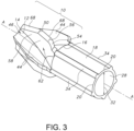
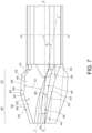
- FIGS. 1-3 , 4 , 5 , and 6 illustrate an embodiment of a bone cutter comprising a cutting head 10 of the present invention.
- the cutting head 10 comprises a frusto-conical body 12 that extends lengthwise along a longitudinal axis A-A from a cutting head distal end 14 to a cutting head proximal end 16.
- a barrel portion 18 extends in a proximal direction along longitudinal axis A-A from a barrel portion distal end at the cutting head proximal end 16 to a barrel proximal end 20.
- the cutting head 10 comprises a distal end wall 22 having an end wall surface 24.
- the end wall surface 24 is oriented perpendicular to longitudinal axis A-A.
- the cutting head 10 provides for the cutting and removal of bone and tissue from a bone during a surgical procedure, for example, during reaming of an intramedullary canal in a femur.
- the barrel portion 18 provides for the attachment of the cutting head 10 to a drive shaft 26 ( FIG. 1 ).
- a cavity 28, dimensioned to receive the drive shaft 26, extends longitudinally within the barrel portion 18 from the barrel portion proximal end 20 to the cutting head proximal end 16.
- the cavity 28 is dimensioned to provide an interference fit with the drive shaft 26.
- the cavity 28 has a length 30 that may range from about 0.5 cm to about 2 cm and a diameter 32 ( FIG. 2 ) that ranges from about 0.5 cm to about 1 cm.
- a plurality of spaced apart ribs 34 may extend longitudinally along the length of the barrel exterior surface.
- a lumen 36 extends along the longitudinal axis A-A through the bone cutting head 10. As illustrated in FIGS. 1 and 3 , the lumen 36 extends through the cutting head distal end wall 22, forming a lumen opening 38 therethrough. The lumen 36 extends longitudinally through the cutting head 10 and meets the cavity 28 within the barrel portion 18. The lumen 36 provides a channel for removal of cut bone and tissue from, for example, the intramedullary canal during a surgical procedure. In addition, the lumen 36 provides an opening for a guidewire (not shown) to extend therethrough. The guidewire may be used to help to control movement and positioning of the cutting head 10 within the intramedullary canal. In a preferred embodiment, the lumen 36 has a diameter 40 that ranges from about 0.1 cm to about 1 cm and a length 42 that ranges from about 0.1 cm to about 1 cm.
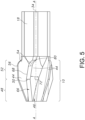
- a plurality of spaced apart blades 44 extend radially from an exterior surface 46 of the frusto-conical body 12.
- Each of the blades 44 has a distal frusto-conical section 48 that provides for coarse cutting and is delineated by a frusto-conical transition line 50 from a proximal frusto-conical section 52 that provides for fine cutting.
- a frusto-conical transition line 50 from a proximal frusto-conical section 52 that provides for fine cutting.
- five spaced apart blades 44 are shown.
- the cutting head 10 may be designed with at least two spaced apart blades 44 that extend outwardly from the exterior surface 46 of the frusto-conical body 12.
- the proximal frusto-conical section 52 extends from the frusto-conical transition line 50 in a proximal direction toward a tail blade segment 54.
- the proximal frusto-conical section 52 and the tail blade segment 54 meet at a tail blade segment transition line 56 that is positioned proximal of the frusto-conical transition line 50.
- the tail blade segment 54 extends from the tail blade segment transition line 56 to the cutting head proximal end 16.
- each of the blades 44 comprises a cutting sidewall 58 having opposed leading and trailing blade sidewall surfaces 60, 62 that extend outwardly from the exterior surface 46 of the body 12.
- the leading sidewall surface 60 will also be referred to hereinafter as the "compound cutting surface 60".
- the outwardly extending leading and trailing surfaces 60, 62 define a blade width 64 therebetween.
- the blade width 64 may range from about 0.1 cm to about 0.5 cm.
- the outwardly extending leading and trailing sidewall surfaces 60, 62 meet at a blade relief surface 66 that extends therebetween.
- the relief surface 66 extends from the cutting head distal end 14 to the cutting head proximal end 16 along the distal frusto-conical section 48, proximal frusto-conical section 52, and tail blade segments 54.
- a tissue cutting edge 68 is formed at the intersection of the leading sidewall surface 60 and the relief surface 66.
- the tissue cutting edge 68 extends from the end wall surface 24, along the distal and proximal frusto-conical sections 48, 52 to the tail blade transition line 56.
- the cutting head 10 is rotated about the longitudinal axis A-A in either a clockwise or counterclockwise direction. In a preferred embodiment, the cutting head 10 is rotated in a clockwise direction so that the tissue cutting edge 68 leads the trailing sidewall surface 62 as the cutting head 10 is rotated within the intramedullary canal.
- the blades 44 are oriented so that the leading surface 60 of one blade 44 faces the trailing surface 62 of an adjacent blade 44.
- a gap 70 ( FIGS. 6A-6F ), forming a clearance space therebetween, resides between two adjacently positioned blades 44.
- the gap 70 resides between the leading and trailing sidewall surfaces 60, 62 that are immediately adjacent to each other.
- the gap 70 is dimensioned to provide space for the removal of cut bone and tissue during a surgical procedure.
- the gap 70 may range from about 0.3 cm to about 2 cm.
- the proximal frusto-conical section 52 comprises a height 72 that extends from the exterior surface 46 of the frusto-conical body 12 to the relief surface 66 that extends along the proximal frusto-conical section 52.
- the height 72 of the proximal frusto-conical section 52 determines the diameter of the reamed opening created by the cutting head 10 within the intramedullary canal.
- the proximal frusto-conical section height 72 may range from about 0.5 cm to about 1 cm.
- the distal frusto-conical section 48 is designed to initially bore into bone, for example, the intramedullary space.
- the positively sloping relief surface 66 along the distal frusto-conical section 48 is designed to coarsely cut the intramedullary material and move it to the tissue cutting edge 68 along the proximal frusto-conical section 52, which in turn, cuts the intramedullary tissue matter into more finely comminuted matter.
- the cut material flows over the exterior surface of the cutting head 10 between the gaps 70.
- the tissue cutting edge 68 that extends along the distal frusto-conical section 48 is oriented at a distal frusto-conical section lead-in angle ⁇ .
- the distal frusto-conical section lead-in angle is defined with respect to imaginary plane B-B that is coincident end wall surface 24 and oriented perpendicular to longitudinal axis A-A.
- the distal frusto-conical section lead-in angle ⁇ extends between imaginary line C-C that is coincident with the tissue cutting edge 68 along the distal frusto-conical section 48, and imaginary plane B-B that is positioned perpendicular to longitudinal axis A-A.
- the distal frusto-conical lead-in angle ⁇ may range from about 10° to about 80°. In a preferred embodiment, the distal frusto-conical lead-in angle ⁇ may range from about 40° to about 70°.
- the tail segment 54 of each blade 44 of the cutting head 10 further extends distally to the proximal frusto-conical section 52 meeting the distal frusto-conical section 48.
- the tail segment extends distally from the cutting head proximal end 16.
- the maximum diameter of the cutting head 10 is at the junction of a distal end of the tail segment 54 and a proximal end of the proximal frusto-conical section 52.
- the cutting edge 68 in the proximal frusto-conical section 52 extends distally and downwardly toward the longitudinal axis A-A to a frusto-conical transition point 80, which resides along the frusto-conical transition line 50.
- the incline of the cutting edge 68 in the distal frusto-conical section 48 extends distally and downwardly toward the longitudinal axis A-A at a greater rate than the incline of the cutting edge 68 in the proximal frusto-conical section 52.
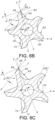
- FIGS. 6A to 6F being just a few of them.
- an imaginary line D-D extends along the blade relief surface 66.
- Another imaginary line E-E intersects the longitudinal axis A-A and the outermost endpoint of the cutting edge 68, it being understood that the outermost endpoint of edge 68 is a point in each cross-section.
- a third imaginary line F-F aligned perpendicular to line E-E extends through the outermost endpoint of the cutting edge 68.
- a relief angle ⁇ is then defined between lines D-D and F-F.
- FIG. 6A adjacent to, but spaced somewhat proximal the end wall surface 24, the relief angle ⁇ is about 35°.
- FIG. 6B is a cross-section taken about half-way between the end wall surface 24 and the frusto-conical transition point 80 where the relief angle ⁇ is about 32°.
- FIG. 6C is a cross-section taken adjacent to but spaced somewhat distal the frusto-conical transition point 80 where the relief angle is about 28°.
- the relief angle ⁇ for each of the plurality of cutting blades 44 in the distal frusto-conical section 48 ranges from about 40° at the end wall surface 24 to about 30° at the frusto-conical transition point 80.
- the average slope of the relief angle within the distal frusto-conical section 48 is about -3.01°/mm from the distal end wall surface 24 to the frusto-conical transition point 80. It is understood that each of the plurality of blades 44 has a similar relief angle at the same cross-section.
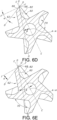
- the relief angle ⁇ is measured in a similar manner as shown in FIGS. 6A to 6C for the relief angle in the distal frusto-conical section 48.
- the relief angle again defined as the angle between the imaginary line D-D extending along the blade relief surface 66 and imaginary line F-F aligned perpendicular to line E-E extending through axis A-A and the outermost endpoint of the cutting edge 68, is about 26°.
- the relief angle is about 21.5°.
- the relief angle is about 14.5°.
- the relief angle ⁇ gradually declines from a maximum of about 40° at the distal end surface 24 to a minimum of about 21° at the proximal end of the proximal frusto-conical section 52.
- the average slope of the relief angle ⁇ within the proximal frusto-conical section 52 is about -2.22°/mm extending from the frusto-conical transition point 80 to the proximal end of the proximal frusto-conical section 52.
- FIGS. 6A to 6F further show that the sidewall 58 for each blade 44 has a leading or partially curved, partially planar compound cutting surface 60 extending proximally from the distal end surface 24 to the proximal end of the proximal frusto-conical section 52. Beginning at the cross-section of the distal end surface 24 and extending proximally, the compound cutting surface 60 gradually changing from a predominantly curved surface to a mostly planar surface.
- the compound cutting surface 60 of sidewall 58 is mostly first curved and then becomes gradually more planar.
- a line along a cross-section coinciding with the distal end surface 24 and intersecting the curvature of the curved portion of the cutting surface 60 at a tangent point has the tangent point coinciding with the outermost endpoint of the cutting edge 68, which as defined below equates to a rake angle of 0°.
- the distal end surface cross-section is the only cross-section in which the line is tangent to the curved portion of the cutting surface 60 of sidewall 58 and coincides with the outermost endpoint of the cutting edge 68.
- the compound cutting surface 60 of sidewall 58 has an increasingly larger planer surface portion immediately adjacent to the outermost endpoint of the cutting edge 68.
- the transition point between the planar portion of the compound cutting surface 60 and the curved portion of that cutting surface moves closer and closer toward the longitudinal axis and further and further away from the outermost endpoint of the cutting edge 68 until there is substantially no curvature to the cutting surface 60 of the sidewall 58.
- the cutting surface 60 of sidewall 58 is generally a planar surface at the proximal end of the proximal frusto-conical section 52.
- FIG. 6A This is illustrated in FIG. 6A in the distal frusto-conical section 48 where imaginary line G-G intersects at a point where an outer planar portion meets a curved portion of the cutting surface 60 of sidewall 58, this point being spaced from the outermost endpoint of the cutting edge 68.
- a rake angle ⁇ is then defined between line E-E (intersecting the longitudinal axis A-A and the outermost endpoint of the cutting edge 68) and line G-G.
- the rake angle ⁇ is about 3°.
- FIG. 6B which is a cross-section taken about half-way between the end wall surface 24 and the frusto-conical transition point 80, the rake angle ⁇ is about 8°.
- the rake angle ⁇ between line G-G and line E-E is about 12°.
- the rake angle ⁇ for the cutting surface 60 for each of the plurality of cutting blades 44 in the distal frusto-conical section 48 ranges from about 0° at the end wall surface 24 to about 12° at the frusto-conical transition point 80 of the cutting edge 68.
- the average slope of the rake angle ⁇ within the distal frusto-conical section 48 is about 2.08°/mm.
- this angle is measured in a similar manner as shown in FIGS. 6B and 6C for the rake angle in the distal frusto-conical section 48.
- the rake angle between line E-E (intersecting the longitudinal axis A-A and the outermost endpoint of the cutting edge 68) and line G-G coincident to the planar surface portion of the sidewall 58 is about 13.5°.
- the rake angle is about 18.5°.
- the rake angle is about 22°.
- the rake angle ⁇ gradually increases from a minimum of about 0° at the distal end wall surface 24 to a maximum of about 22° at the blade tail transition line 56 within the tail segment 54. It is noted that the average slope of the rake angle ⁇ within the proximal frusto-conical section 52 is about 2.11°/mm.
- the blade tail segment 54 has a curved blade relief surface 66 that extends from the blade tail transition line 56 to the exterior surface 46 of the frusto-conical body 12. Unlike the distal and proximal frusto-conical sections 48, 52, the tail segment 54 is not intended to cut tissue or bone. As illustrated, the proximal blade relief surface 66 is constructed such that it curves downward and away from the tissue cutting edge 68 of the proximal frusto-conical section 52. In an embodiment, the tail segment 54 helps to stabilize the cutting head blade 44 as it reams within the intramedullary canal. The sloping surface of the tail relief surface 66 also enables the reamer to traverse the cut canal when the reamer is extracted.
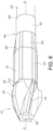
- FIG. 7 illustrates a magnified side view of an embodiment of the cutting head 10 of the present invention.
- imaginary plane H-H is aligned perpendicular to longitudinal axis A-A.
- each blade 44 of the cutting head 10 comprises a blade deflection angle ⁇ in which the leading surface 60 of the proximal frusto-conical section 52 deflects at an angle from the leading sidewall surface 60 of the distal frusto-conical section 48 at the frusto-conical transition point 80.
- the blade deflection angle ⁇ is defined as the angle that extends between imaginary plane H-H, that lies perpendicular to longitudinal axis A-A and imaginary line I-I that is coincident with the leading sidewall surface 60 of the proximal frusto-conical section 52.
- the blade deflection angle ⁇ may range from about 70° to about 90°.
- the cutting head 10 and barrel portion 18 may be formed having a unitary body construction.
- the cutting head 10 and barrel portion 18 may be formed using a metal injection molding process in which powdered metal such as 17-4 stainless steel mixed with a binder material is injected into a mold that defines the cutting head and barrel portion shape. After the shape of the cutting head and barrel portion are formed within the mold, the molded part is them heat treated at a temperature ranging from about 100°C to about 500°C.
- the bone cutter may also be formed from other metallic material such as, but not limited to, ferrous alloys, aluminum, precious metals, titanium alloys, nickel, nickel-base super alloys, molybdenum, molybdenum-copper, tungsten alloys, cobalt-chromium, carbides, ceramic, and cermets such as Fe-TiC.
- the cutting head 10 and barrel portion 18 may also be formed from polymeric material materials, such as but are not limited to, polyetheretherketone (PEEK), polyacrylamide (PARA) and acrylonitrile butadiene styrene (ABS).
- PEEK polyetheretherketone
- PARA polyacrylamide
- ABS acrylonitrile butadiene styrene
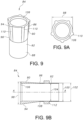
- FIGS. 8 , 9, 9A, and 9B illustrate an embodiment of an optional sleeve 84 having spaced apart distal and proximal sleeve ends 86, 88.
- the sleeve distal end 86 may be removably attached to the proximal end of the cutting head 10.
- the sleeve 84 forms a transition between the barrel portion proximal end 20 and the drive shaft 26.
- the sleeve 84 is constructed to provide an improved seal between the drive shaft 26 and the cutting head 10.
- the sleeve 84 is designed to minimize the possibility that the junction between the cutting head 10 and drive shaft 26 at the barrel proximal end 20 may obstruct insertion or removal of the cutting head 10 within the intramedullary canal.
- the sleeve 84 comprises a collar 90 that extends to a tube portion 92.
- the collar 90 has a tapered construction comprising a distal end outer diameter 98 that is greater than a proximal end outer diameter 100.
- the tube portion 92 comprising a tube outer diameter 102 and a tube inner diameter 104 that extends along longitudinal axis A-A from the collar proximal end 96.
- the collar distal end 94 is dimensioned to receive the barrel proximal end 20.
- the collar 90 may comprise a chamfer 106 that is formed within the collar interior at the collar distal end 94.
- the chamfer 106 extends annularly about the interior of the collar distal end 94.
- the chamfer 106 forms a surface that is configured to physically contact the proximal end of the barrel portion 18.
- An adhesive positioned along the chamfer surface may be used to connect the barrel portion 18 to the sleeve 84.
- the collar proximal end outer diameter 100 is greater than the tube portion outer diameter 102. This preferred relationship between the two diameters of the collar and tube portions allows for an annular ledge 108 to be formed at the collar proximal end 96.
- a plurality of spaced apart collar ribs 110 may extend longitudinally along the collar exterior surface. These collar ribs 110 are dimensioned similarly to the exterior ribs that extend along the barrel portion exterior surface.
- a ring 112 such as a ring of shrink wrap or other compression material, may be positioned around the tube outer diameter 102. As such, the ring 112 is designed to constrict the tube portion 92 around the shaft 24 positioned within the tube 92, thereby forming an interference fit therebetween.
- FIGS. 10 and 11 illustrate an embodiment of a shaft attachment interface 114 which may be used to attach the shaft 24 to the cutting head 10.
- the shaft attachment interface 114 may comprise a cutout portion 116 that is designed to receive a projection 118 having a corresponding cross-sectional shape in a keyed mated interface.
- the projection 118 constructed at the shaft distal end, is designed to be received within the cutout portion 116 having a corresponding cross-sectional shape, within a portion of the barrel 18.
- the projection 118 may be received within the cutout portion 116 in a dovetail relationship. In the embodiment shown in FIG.
- the cutout portion 116 may comprise at least one groove 120 that is formed within the sidewall of the barrel 18 and that extends perpendicular to the longitudinal axis.
- a ridge 122 that corresponds to the dimension of the groove 120 extends outwardly from the shaft distal end. As shown in FIG. 10 , the ridge 122 formed at the distal end of the drive shaft is received within the groove 120 formed within the barrel sidewall in a mated dovetail relationship.
- the cutout portion 116 and the corresponding shaped projection 118 are not limited to the embodiment illustrated in FIGS. 10 and 11 . It is further contemplated that the cutout portion 116 formed within the barrel portion 18 may be constructed of a plurality of nonlimiting shapes such that the shaft distal end is formed of a corresponding shape that is capable of being received in a mated relationship therewithin. For example, the cutout portion 116 may be of a cross-sectional shape having a curved geometry, a rectangle geometry, triangular geometry or star geometry. It is also contemplated that that cutout portion 116 may be formed within the shaft distal end and the corresponding shaped projection 118 is formed extending from the barrel proximal end 20.
- the reamer cutting head of the present invention provides for a low cost flexible single use intramedullary cutting tool.
- the present invention does not require additional grinding or re-sharpening procedures which ensures optimal sharpness and sterilization.
- the features of the present invention provide for an efficient intramedullary cutting tool with an optimized cutting design that enhances reaming efficiency and effectiveness.
Claims (12)
- Outil de coupe d'os configuré pour une connexion détachable à une source de mouvement rotatif, l'outil de coupe d'os comprenant :a) une tête de coupe (10) s'étendant distalement le long d'un axe longitudinal (A - A) à partir d'une extrémité proximale jusqu'à une surface d'extrémité distale ; etb) au moins deux lames de coupe espacées (44) supportées par la tête de coupe (10), chaque lame de coupe (44) comprenant une surface de relief (66) se trouvant entre des surfaces de paroi latérale de coupe et arrière opposées (60, 62), dans lequel un bord de coupe de tissu (68) se trouve à une intersection de la surface de paroi latérale de coupe et de la surface de paroi latérale de relief (60, 62) ; le bord de coupe de tissu (68) ayant une forme tronconique s'étendant distalement et vers le bas en direction de la surface d'extrémité distale (14) de la tête de coupe (10) ;c) dans lequel, par rapport à une section transversale quelconque alignée normalement à l'axe longitudinal et prise de la surface d'extrémité distale (14) de la tête de coupe (10) à une extrémité proximale de la lame de coupe (44),(i) le bord de coupe de tissu (68) comprend :A) une première ligne imaginaire qui coïncide avec la surface de relief de lame (66) ;B) une seconde ligne imaginaire qui coupe l'axe longitudinal et le point d'extrémité le plus extérieur du bord de coupe de tissu (68) ; etC) une troisième ligne imaginaire qui est normale à la seconde ligne imaginaire et coupe le point d'extrémité le plus externe du bord de coupe de tissu (68) ; dans lequelD) un angle de relief défini entre les première et troisième lignes imaginaires est compris entre 40 ° au niveau de la surface d'extrémité distale de la tête de coupe (10) et 21 ° à l'extrémité proximale de la lame de coupe (44) ; et(ii) la surface de paroi latérale de coupe (60, 62) a une partie de surface de coupe plane s'étendant à partir du bord de coupe de tissu (68) vers l'axe longitudinal jusqu'à un point de transition où la partie de surface de coupe plane rencontre une partie de surface de coupe incurvée de la section transversale de sorte que, par rapport à l'une quelconque des sections transversales, la surface de paroi latérale de coupe comprenne :A) A une quatrième ligne imaginaire qui coupe le point de transition et le point d'extrémité le plus extérieur du bord de coupe de tissu (68) ; etB) un angle d'attaque défini entre les seconde et quatrième lignes imaginaires qui est compris entre 0° au niveau de la surface d'extrémité distale de la tête de coupe et 19 ° à une extrémité proximale de la forme tronconique du bord de coupe de tissu (68).
- Outil de coupe d'os selon la revendication 1, dans lequel le bord de coupe de tissu (68) comprend une partie tronconique proximale qui rencontre une partie tronconique distale au niveau d'un point de transition tronconique, la partie tronconique proximale s'étendant vers le bas et distalement vers l'axe longitudinal au niveau d'une pente de partie proximale, et la partie tronconique distale s'étendant vers le bas et distalement vers l'axe longitudinal au niveau d'une pente de partie distale qui est supérieure à la pente de partie proximale.
- Outil de coupe d'os selon la revendication 2, dans lequel, par rapport à l'axe longitudinal, un rayon externe maximal de chacune des au moins deux lames de coupe est à une extrémité proximale de la partie tronconique proximale.
- Outil de coupe d'os selon la revendication 3, dans lequel un angle de relief proximal dans la partie tronconique proximale est compris entre 21 ° et 28 ° au niveau du point de transition tronconique, et un angle de relief distal dans la partie tronconique distale est compris entre 28° et 40° au niveau de la surface d'extrémité distale de la tête de coupe (10).
- Outil de coupe d'os selon la revendication 4, dans lequel l'angle de relief proximal dans la partie tronconique proximale a une pente d'angle de relief proximal de -2,22°/mm s'étendant vers le bas et distalement vers l'axe longitudinal, et l'angle de relief distal dans la partie tronconique distale a une pente d'angle de relief distal de -3,01°/mm s'étendant vers le bas et distalement vers l'axe longitudinal.
- Outil de coupe d'os selon la revendication 1, dans lequel, au niveau de la surface d'extrémité distale de la tête de coupe (10) où l'angle d'attaque est de 0°, la surface de paroi latérale de coupe ne comporte pas de parties planes, et la quatrième ligne imaginaire coupe un point de tangence de la partie incurvée du bord de coupe de tissu (68), le point de tangence coïncidant avec le point d'extrémité le plus extérieur du bord de coupe de tissu (68).
- Outil de coupe d'os selon la revendication 6, dans lequel, avec une première section transversale coïncidant avec la surface d'extrémité distale de la tête de coupe (10) et au niveau d'une seconde section transversale étant proximale à la première section transversale, le point de transition est espacé d'une première distance à partir du point d'extrémité le plus externe du bord de coupe de tissu (68), et au niveau d'une troisième section transversale proximale à la seconde section transversale, le point de transition est espacé d'une seconde distance à partir du point d'extrémité le plus externe du bord de coupe de tissu (68), la seconde distance étant supérieure à la première distance.
- Outil de coupe d'os selon la revendication 3, dans lequel un angle d'attaque proximal dans la partie tronconique proximale du bord de coupe de tissu (68) est compris entre 12° et 19° au niveau du point de transition, et un angle d'attaque distal dans la partie tronconique distale du bord de coupe de tissu (68) est compris entre 19 ° et 0 ° au niveau de la surface d'extrémité distale de la tête de coupe.
- Outil de coupe d'os selon la revendication 8, dans lequel l'angle d'attaque proximal dans la partie tronconique proximale a une pente d'angle d'attaque proximale de 2, 11 ° /mm, et l'angle d'attaque distal dans la partie tronconique distale a une pente d'angle d'attaque distal de 2,08°/mm.
- Outil de coupe d'os selon la revendication 1, comprenant une partie de cylindre proximale (18) de la tête de coupe (10), la partie de cylindre (18) ayant une cavité (28) qui est configurée pour recevoir de manière détachable un arbre d'entraînement (26).
- Outil de coupe d'os selon la revendication 1, comprenant une partie de découpe proximale de la tête de coupe (10), la partie de découpe ayant une géométrie en coupe transversale orientée perpendiculairement à l'axe longitudinal, et dans lequel la partie de découpe est configurée pour recevoir de manière détachable une saillie d'un arbre d'entraînement (26).
- Outil de coupe d'os selon la revendication 13, comprenant en outre une bague (90) qui peut être connectée à un arbre d'entraînement (26), la bague (90) ayant une extrémité proximale de bague (96) s'étendant le long de l'axe longitudinal jusqu'à une extrémité distale de bague (94) connectée à la partie de cylindre (18), dans lequel l'extrémité proximale de bague (96) a un premier diamètre extérieur et l'extrémité distale de bague (94) a un second diamètre extérieur, le premier diamètre extérieur de bague est inférieur au second diamètre extérieur de bague pour ainsi fournir une connexion sûre de l'outil de coupe d'os à un arbre d'entraînement (26).
Applications Claiming Priority (1)
| Application Number | Priority Date | Filing Date | Title |
|---|---|---|---|
| US201662294642P | 2016-02-12 | 2016-02-12 |
Publications (3)
| Publication Number | Publication Date |
|---|---|
| EP3205294A2 EP3205294A2 (fr) | 2017-08-16 |
| EP3205294A3 EP3205294A3 (fr) | 2017-10-11 |
| EP3205294B1 true EP3205294B1 (fr) | 2024-02-14 |
Family
ID=58018025
Family Applications (1)
| Application Number | Title | Priority Date | Filing Date |
|---|---|---|---|
| EP17155887.7A Active EP3205294B1 (fr) | 2016-02-12 | 2017-02-13 | Têtes de coupe pour alésoirs intramédullaires |
Country Status (2)
| Country | Link |
|---|---|
| US (1) | US10335170B2 (fr) |
| EP (1) | EP3205294B1 (fr) |
Families Citing this family (8)
| Publication number | Priority date | Publication date | Assignee | Title |
|---|---|---|---|---|
| WO2018035034A1 (fr) * | 2016-08-14 | 2018-02-22 | Greatbatch Ltd. | Tête de coupe pour alésoir intramédullaire |
| US9855675B1 (en) * | 2016-09-20 | 2018-01-02 | RELIGN Corporation | Arthroscopic devices and methods |
| US11696769B2 (en) * | 2017-12-22 | 2023-07-11 | Viant As&O Holdings, Llc | Thermally sensitive retention mechanism for orthopedic cutting instruments |
| EP3745970B1 (fr) | 2018-03-06 | 2023-08-23 | Viant AS&O Holdings, LLC | Tête de coupe d'alésoir extensible |
| US10582933B2 (en) * | 2018-03-22 | 2020-03-10 | Capstone Surgical Techologies, LLC | Oscillating surgical cutting tool |
| USD915591S1 (en) * | 2019-01-25 | 2021-04-06 | Beijing Smtp Technology Co., Ltd. | Ultrasonic cutter head for medical purpose |
| CN110840516A (zh) * | 2019-12-02 | 2020-02-28 | 北京市春立正达医疗器械股份有限公司 | 开孔刀头和应用其的孔道开路器 |
| CN111938743B (zh) * | 2020-07-17 | 2021-07-20 | 天衍医疗器材有限公司 | 一种胫骨截骨工具系统 |
Family Cites Families (25)
| Publication number | Priority date | Publication date | Assignee | Title |
|---|---|---|---|---|
| US4473070A (en) * | 1983-01-05 | 1984-09-25 | Regents Of The University Of Michigan | Intramedullary reamer |
| US4706659A (en) | 1984-12-05 | 1987-11-17 | Regents Of The University Of Michigan | Flexible connecting shaft for intramedullary reamer |
| US4751922A (en) * | 1986-06-27 | 1988-06-21 | Dipietropolo Al | Flexible medullary reamer |
| US5122134A (en) | 1990-02-02 | 1992-06-16 | Pfizer Hospital Products Group, Inc. | Surgical reamer |
| DE69415804T2 (de) * | 1993-05-27 | 1999-05-20 | Howmedica | Flexible reibahle für einen markkanal |
| DE29511872U1 (de) | 1995-07-22 | 1995-09-28 | Howmedica Gmbh | Bohrkopf zum Aufbohren von Knochenkanälen |
| EP1253862A4 (fr) | 1999-02-01 | 2003-09-17 | Garland U Edwards | Alesoir-fraise chirurgical |
| US6918913B2 (en) | 1999-05-14 | 2005-07-19 | Precimed S.A. | Tool bit drive shaft connection and method |
| FR2802080B1 (fr) * | 1999-12-13 | 2002-03-15 | Jacques Afriat | Ensemble pour la mise en place d'une tige femorale de prothese de hanche sur un femur |
| US20030176868A1 (en) | 2002-02-22 | 2003-09-18 | Pepper John R. | Long bone reaming apparatus and method |
| US6949101B2 (en) | 2002-03-29 | 2005-09-27 | Depuy Orthopaedics, Inc. | Medical instrument for milling a curved path in bone and procedure |
| US7074224B2 (en) * | 2003-06-25 | 2006-07-11 | Depuy Products, Inc. | Modular tapered reamer for bone preparation and associated method |
| US7867234B2 (en) | 2003-10-06 | 2011-01-11 | Howmedica Osteonics Corp. | Reamer bushing |
| US7229457B2 (en) | 2003-10-31 | 2007-06-12 | Medtronic, Inc. | Surgical instrument with adjustable rotary cutting tool and method of cutting |
| DE102005016870A1 (de) * | 2005-04-07 | 2006-10-12 | Kaltenbach & Voigt Gmbh | Medizinisches, insbesondere dentalmedizinisches, Handstück mit einer lösbaren Kupplung für einen Werkzeughalter |
| US20080132929A1 (en) * | 2005-07-19 | 2008-06-05 | O'sullivan Denis F | Surgical bur with anti-chatter flute geometry |
| US7803159B2 (en) | 2006-11-29 | 2010-09-28 | Mi4Spine, Llc | Disc space preparation device for spinal surgery |
| ES2323255B1 (es) * | 2007-03-26 | 2010-04-19 | Soadco, S.L. | Sistema de acoplamiento amovible para herramientas quirurgicas motorizadas. |
| CH702093A1 (fr) | 2009-10-28 | 2011-04-29 | Chirmat Sarl | Arbre d'entraînement pour alésoir chirurgical. |
| US8454608B2 (en) | 2009-12-15 | 2013-06-04 | Greatbatch Ltd. | Disposable flex reamer |
| US20130006248A1 (en) * | 2010-03-19 | 2013-01-03 | CPL Holdings Pty. Ltd. | Drill bit |
| CN201862859U (zh) | 2010-11-16 | 2011-06-15 | 四川天虎工具有限责任公司 | 不等齿锥度铰刀 |
| US9095356B2 (en) * | 2012-05-30 | 2015-08-04 | Depuy (Ireland) | Tibial trial instruments and method of using same |
| DE202012104364U1 (de) * | 2012-11-13 | 2013-03-05 | Trokamed Gmbh | Markraumbohrer |
| US20160199145A1 (en) * | 2015-01-09 | 2016-07-14 | Biomet Manufacturing, Llc | Method and apparatus for measurement of intramedullary length with radiopaque markings |
-
2017
- 2017-02-13 US US15/431,014 patent/US10335170B2/en active Active
- 2017-02-13 EP EP17155887.7A patent/EP3205294B1/fr active Active
Also Published As
| Publication number | Publication date |
|---|---|
| US10335170B2 (en) | 2019-07-02 |
| EP3205294A2 (fr) | 2017-08-16 |
| US20170231643A1 (en) | 2017-08-17 |
| EP3205294A3 (fr) | 2017-10-11 |
Similar Documents
| Publication | Publication Date | Title |
|---|---|---|
| US10405872B2 (en) | Cutting head for an intramedullary reamer | |
| EP3205294B1 (fr) | Têtes de coupe pour alésoirs intramédullaires | |
| US9107677B2 (en) | Disposable surgical hemispherical cutter for convex and concave surfaces | |
| EP2335617B1 (fr) | Aléseur flexible jetable | |
| US8075563B2 (en) | Resurfacing reamer with cutting struts | |
| US5931841A (en) | Combination broacher-reamer for use in orthopaedic surgery | |
| US7918856B2 (en) | Guided reamer system for reshaping bone | |
| US9763676B2 (en) | Surgical blade for use with an acetabular cup remover to remove bone around an acetabular cup | |
| EP3313320B1 (fr) | Foret étagé | |
| AU2021286311B2 (en) | A surgical rotational cutting tool | |
| US9282978B2 (en) | Disposable cylindrical cutter | |
| US20220409384A1 (en) | Annular cutting tools for resecting a bone graft and related methods | |
| EP3370628B1 (fr) | Couteau rotatif pour préparer le fémur pour un implant de hanche de resurfaçage | |
| EP3508176B1 (fr) | Système d'instrument chirurgical orthopédique comprenant un composant d'essai de tige | |
| WO1998049948A1 (fr) | Tete de perçage de cavite medullaire | |
| US10441297B2 (en) | Sounder for sizing bone implant |
Legal Events
| Date | Code | Title | Description |
|---|---|---|---|
| PUAI | Public reference made under article 153(3) epc to a published international application that has entered the european phase |
Free format text: ORIGINAL CODE: 0009012 |
|
| STAA | Information on the status of an ep patent application or granted ep patent |
Free format text: STATUS: THE APPLICATION HAS BEEN PUBLISHED |
|
| AK | Designated contracting states |
Kind code of ref document: A2 Designated state(s): AL AT BE BG CH CY CZ DE DK EE ES FI FR GB GR HR HU IE IS IT LI LT LU LV MC MK MT NL NO PL PT RO RS SE SI SK SM TR |
|
| AX | Request for extension of the european patent |
Extension state: BA ME |
|
| PUAL | Search report despatched |
Free format text: ORIGINAL CODE: 0009013 |
|
| AK | Designated contracting states |
Kind code of ref document: A3 Designated state(s): AL AT BE BG CH CY CZ DE DK EE ES FI FR GB GR HR HU IE IS IT LI LT LU LV MC MK MT NL NO PL PT RO RS SE SI SK SM TR |
|
| AX | Request for extension of the european patent |
Extension state: BA ME |
|
| RIC1 | Information provided on ipc code assigned before grant |
Ipc: A61B 17/16 20060101AFI20170907BHEP |
|
| STAA | Information on the status of an ep patent application or granted ep patent |
Free format text: STATUS: REQUEST FOR EXAMINATION WAS MADE |
|
| 17P | Request for examination filed |
Effective date: 20180411 |
|
| RBV | Designated contracting states (corrected) |
Designated state(s): AL AT BE BG CH CY CZ DE DK EE ES FI FR GB GR HR HU IE IS IT LI LT LU LV MC MK MT NL NO PL PT RO RS SE SI SK SM TR |
|
| GRAP | Despatch of communication of intention to grant a patent |
Free format text: ORIGINAL CODE: EPIDOSNIGR1 |
|
| STAA | Information on the status of an ep patent application or granted ep patent |
Free format text: STATUS: GRANT OF PATENT IS INTENDED |
|
| INTG | Intention to grant announced |
Effective date: 20200317 |
|
| GRAJ | Information related to disapproval of communication of intention to grant by the applicant or resumption of examination proceedings by the epo deleted |
Free format text: ORIGINAL CODE: EPIDOSDIGR1 |
|
| STAA | Information on the status of an ep patent application or granted ep patent |
Free format text: STATUS: REQUEST FOR EXAMINATION WAS MADE |
|
| INTC | Intention to grant announced (deleted) | ||
| STAA | Information on the status of an ep patent application or granted ep patent |
Free format text: STATUS: EXAMINATION IS IN PROGRESS |
|
| 17Q | First examination report despatched |
Effective date: 20200910 |
|
| STAA | Information on the status of an ep patent application or granted ep patent |
Free format text: STATUS: EXAMINATION IS IN PROGRESS |
|
| P01 | Opt-out of the competence of the unified patent court (upc) registered |
Effective date: 20230524 |
|
| GRAP | Despatch of communication of intention to grant a patent |
Free format text: ORIGINAL CODE: EPIDOSNIGR1 |
|
| STAA | Information on the status of an ep patent application or granted ep patent |
Free format text: STATUS: GRANT OF PATENT IS INTENDED |
|
| INTG | Intention to grant announced |
Effective date: 20231115 |
|
| RIN1 | Information on inventor provided before grant (corrected) |
Inventor name: SCHWARTZKOPF, CURTIS J. Inventor name: SAUSEN, KARI ANN Inventor name: VICTOR, GARY C. |
|
| GRAS | Grant fee paid |
Free format text: ORIGINAL CODE: EPIDOSNIGR3 |
|
| GRAA | (expected) grant |
Free format text: ORIGINAL CODE: 0009210 |
|
| STAA | Information on the status of an ep patent application or granted ep patent |
Free format text: STATUS: THE PATENT HAS BEEN GRANTED |
|
| AK | Designated contracting states |
Kind code of ref document: B1 Designated state(s): AL AT BE BG CH CY CZ DE DK EE ES FI FR GB GR HR HU IE IS IT LI LT LU LV MC MK MT NL NO PL PT RO RS SE SI SK SM TR |
|
| REG | Reference to a national code |
Ref country code: GB Ref legal event code: FG4D |
|
| REG | Reference to a national code |
Ref country code: CH Ref legal event code: EP |
|
| REG | Reference to a national code |
Ref country code: DE Ref legal event code: R096 Ref document number: 602017079090 Country of ref document: DE |
|
| REG | Reference to a national code |
Ref country code: IE Ref legal event code: FG4D |