EP3204681B1 - Vibration isolating insert for a pipe clip - Google Patents
Vibration isolating insert for a pipe clip Download PDFInfo
- Publication number
- EP3204681B1 EP3204681B1 EP15791786.5A EP15791786A EP3204681B1 EP 3204681 B1 EP3204681 B1 EP 3204681B1 EP 15791786 A EP15791786 A EP 15791786A EP 3204681 B1 EP3204681 B1 EP 3204681B1
- Authority
- EP
- European Patent Office
- Prior art keywords
- vibration
- isolating
- strip
- pipe
- pipe clip
- Prior art date
- Legal status (The legal status is an assumption and is not a legal conclusion. Google has not performed a legal analysis and makes no representation as to the accuracy of the status listed.)
- Active
Links
- 239000000463 material Substances 0.000 claims description 108
- 239000004033 plastic Substances 0.000 claims description 44
- 229920003023 plastic Polymers 0.000 claims description 44
- 238000000034 method Methods 0.000 description 15
- 238000005452 bending Methods 0.000 description 6
- 238000001125 extrusion Methods 0.000 description 4
- 238000000465 moulding Methods 0.000 description 4
- 239000002985 plastic film Substances 0.000 description 4
- 238000004080 punching Methods 0.000 description 4
- 229920001971 elastomer Polymers 0.000 description 3
- 238000001746 injection moulding Methods 0.000 description 3
- 238000009434 installation Methods 0.000 description 3
- 238000004519 manufacturing process Methods 0.000 description 3
- 239000002184 metal Substances 0.000 description 3
- 229920006255 plastic film Polymers 0.000 description 3
- 239000012876 carrier material Substances 0.000 description 2
- 239000002131 composite material Substances 0.000 description 2
- 238000005304 joining Methods 0.000 description 2
- 238000003801 milling Methods 0.000 description 2
- 239000005060 rubber Substances 0.000 description 2
- 239000000853 adhesive Substances 0.000 description 1
- 230000001070 adhesive effect Effects 0.000 description 1
- 238000004873 anchoring Methods 0.000 description 1
- 238000010924 continuous production Methods 0.000 description 1
- 239000000806 elastomer Substances 0.000 description 1
- 238000010438 heat treatment Methods 0.000 description 1
- 230000000717 retained effect Effects 0.000 description 1
- 239000007779 soft material Substances 0.000 description 1
- 229920002725 thermoplastic elastomer Polymers 0.000 description 1
- 239000002759 woven fabric Substances 0.000 description 1
Images

Classifications
-
- F—MECHANICAL ENGINEERING; LIGHTING; HEATING; WEAPONS; BLASTING
- F16—ENGINEERING ELEMENTS AND UNITS; GENERAL MEASURES FOR PRODUCING AND MAINTAINING EFFECTIVE FUNCTIONING OF MACHINES OR INSTALLATIONS; THERMAL INSULATION IN GENERAL
- F16L—PIPES; JOINTS OR FITTINGS FOR PIPES; SUPPORTS FOR PIPES, CABLES OR PROTECTIVE TUBING; MEANS FOR THERMAL INSULATION IN GENERAL
- F16L55/00—Devices or appurtenances for use in, or in connection with, pipes or pipe systems
- F16L55/02—Energy absorbers; Noise absorbers
- F16L55/033—Noise absorbers
- F16L55/035—Noise absorbers in the form of specially adapted hangers or supports
-
- B—PERFORMING OPERATIONS; TRANSPORTING
- B29—WORKING OF PLASTICS; WORKING OF SUBSTANCES IN A PLASTIC STATE IN GENERAL
- B29C—SHAPING OR JOINING OF PLASTICS; SHAPING OF MATERIAL IN A PLASTIC STATE, NOT OTHERWISE PROVIDED FOR; AFTER-TREATMENT OF THE SHAPED PRODUCTS, e.g. REPAIRING
- B29C48/00—Extrusion moulding, i.e. expressing the moulding material through a die or nozzle which imparts the desired form; Apparatus therefor
- B29C48/03—Extrusion moulding, i.e. expressing the moulding material through a die or nozzle which imparts the desired form; Apparatus therefor characterised by the shape of the extruded material at extrusion
- B29C48/12—Articles with an irregular circumference when viewed in cross-section, e.g. window profiles
-
- B—PERFORMING OPERATIONS; TRANSPORTING
- B29—WORKING OF PLASTICS; WORKING OF SUBSTANCES IN A PLASTIC STATE IN GENERAL
- B29C—SHAPING OR JOINING OF PLASTICS; SHAPING OF MATERIAL IN A PLASTIC STATE, NOT OTHERWISE PROVIDED FOR; AFTER-TREATMENT OF THE SHAPED PRODUCTS, e.g. REPAIRING
- B29C48/00—Extrusion moulding, i.e. expressing the moulding material through a die or nozzle which imparts the desired form; Apparatus therefor
- B29C48/16—Articles comprising two or more components, e.g. co-extruded layers
-
- F—MECHANICAL ENGINEERING; LIGHTING; HEATING; WEAPONS; BLASTING
- F16—ENGINEERING ELEMENTS AND UNITS; GENERAL MEASURES FOR PRODUCING AND MAINTAINING EFFECTIVE FUNCTIONING OF MACHINES OR INSTALLATIONS; THERMAL INSULATION IN GENERAL
- F16L—PIPES; JOINTS OR FITTINGS FOR PIPES; SUPPORTS FOR PIPES, CABLES OR PROTECTIVE TUBING; MEANS FOR THERMAL INSULATION IN GENERAL
- F16L3/00—Supports for pipes, cables or protective tubing, e.g. hangers, holders, clamps, cleats, clips, brackets
- F16L3/08—Supports for pipes, cables or protective tubing, e.g. hangers, holders, clamps, cleats, clips, brackets substantially surrounding the pipe, cable or protective tubing
- F16L3/12—Supports for pipes, cables or protective tubing, e.g. hangers, holders, clamps, cleats, clips, brackets substantially surrounding the pipe, cable or protective tubing comprising a member substantially surrounding the pipe, cable or protective tubing
Definitions
- the present invention relates to a vibration-isolating insert for a pipe clip, the vibration-isolating insert being adapted to bear against an inner circumference of a substantially annular pipe clip body and ultimately - in use - to be positioned between the outer circumference of a pipe and the pipe clip body, the vibration-isolating insert comprising an elongate strip of vibration-isolating material and having a pipe facing side and a pipe clip facing side.
- a known problem with vibration-isolating inserts in pipe clips is that during installation of pipes, the pipe slides through the pipe clip which is not yet entirely tightened around the pipe. The friction between the pipe surface and the insert may cause the insert to be pulled out of the pipe clip body.
- EP 0413 883 A1 discloses a vibration-isolating insert formed as a profiled strip having substantially a U-shaped cross section.
- the profiled strip has a base strip made of a soft material and lateral wall portions that in use extend beyond the lateral edges of the pipe clip body.
- the respective lateral wall portions have an end portion bent inwardly to grip around respective lateral edges of the pipe clip body.
- the lateral wall portions are made of a harder material than the base strip so as to provide a better anchoring of the vibration-isolating insert in the pipe clip body.
- a disadvantage of this known vibration-isolating insert is that it has a high resistance to bending and it is difficult to adapt to the annular shape of the pipe clip, especially when pipe clips for smaller pipe diameters are to be assembled.
- DE 102007052701 A1 respectively
- EP 2133617 A1 discloses another vibration isolating insert for a pipe clip.
- the present invention has for an object to provide a vibration isolating insert that overcomes or at least mitigates the mentioned disadvantage.
- a vibration-isolating insert for a pipe clip the vibration-isolating insert being adapted to bear against an inner circumference of a substantially annular pipe clip body and ultimately - in use - to be positioned between the outer circumference of a pipe and the pipe clip body, the vibration-isolating insert comprising an elongate strip of vibration-isolating material which has a pipe facing side and a pipe clip facing side, said strip of vibration-isolating material having adjacent either lateral edge thereof a series of discrete exposed hooks of plastics material which is more rigid than the vibration-isolating material, the hooks protruding relative to the pipe clip facing side of the strip of vibration-isolating material.
- the respective series of discrete hooks along the lateral edge portions provide retaining means that in use engage around respective edges of the pipe clip body.
- the bending resistance in longitudinal direction is determined by the continuous part of the insert. Because the hooks are discrete items positioned at regular intervals, they have no or only a relatively small contribution to the bending resistance in the longitudinal direction of the insert.
- the bending resistance of the insert is thus mainly determined by the strip of vibration isolating insert, which is made from a "softer" material such as rubber or a thermoplastic elastomer.
- two opposing hooks located on each of the lateral edge portions are interconnected by a connecting bridge of plastics material to form an integral hook unit.
- the integral hook unit is formed in one piece.
- the connecting bridge provides rigidity in the transverse direction between the two opposing hooks. Thereby the insert in the pipe clip is retained more secure in the pipe clip body.
- said integral hook unit is interconnected with a previous and/or a subsequent integral hook unit by a flexible carrier strip, said carrier strip being attached to said strip of vibration-isolating material.
- the carrier strip is formed in one piece with the connecting bridges of said hook units.
- the carrier strip is preferably substantially thinner than the connecting bridges. Thereby the low bending resistance of the vibration-isolating insert is warranted.
- connection bridge of said unit is, at least partly embedded in the vibration-isolating material of the strip. This results in that the hook unit is anchored firmly in the strip of vibration-isolating material.
- the hook unit furthermore includes two legs connected with one end thereof to the bridge portion, preferably in a centre of the bridge portion, said legs each having at another end a pipe engagement protrusion, wherein the legs are embedded in the vibration-isolating material of the strip and the pipe engagement protrusions protrude outside the vibration-isolating material at the pipe facing side of the strip.
- the invention relates to a vibration-isolating insert for a pipe clip, the vibration-isolating insert being adapted to bear against an inner circumference of a substantially annular pipe clip body and ultimately - in use - to be positioned between the outer circumference of a pipe and the pipe clip body, the vibration-isolating insert comprising an elongate strip of vibration-isolating material and having a pipe facing side and a pipe clip facing side, wherein the vibration-isolating insert has along each of the lateral edges at the pipe clip facing side a substantially L-shaped profile, the L-shaped profile having a first leg extending in alignment with the lateral side of the strip and a second leg extending from the first leg in a transverse direction, wherein the first leg is made of vibration isolating material and the second leg is made of a plastic material which is more rigid than the vibration-isolating material.
- the insert according to this aspect has an L-shaped profile to grip around the pipe clip body, wherein the first leg of the L-shaped profile is, according to the invention, made exclusively of vibration isolating material and the second leg, is exclusively made of a more rigid plastic material.
- this vibration-isolating insert has a lower bending resistance than the known vibration-isolating insert of EP 0413 883 A1 , while the retaining force is increased with regard to inserts which are entirely made of vibration-isolating material.
- the invention also relates to a pipe clip comprising an annular pipe clip body and a vibration-isolating insert as described in the above, wherein the vibration-isolating insert is arranged on the radially seen inner side of the pipe clip body.
- the vibration-isolating insert may bemade by a method, which is currently not claimed.
- the vibration-isolating insert is adapted to bear against an inner circumference of a substantially annular pipe clip body and ultimately - in use - to be positioned between the outer circumference of a pipe and the pipe clip body.
- the method includies the following steps:
- the transverse section of the strip of plastics material may be removed entirely. Another option is that the transverse section is removed to such an extent that a film layer of said plastic material remains. The latter has the advantage that the integrity of the vibration isolating strip can be warranted. Furthermore a better attachment of the vibration-isolating strip and the plastic parts can be expected.
- the vibration-isolating insert is adapted to bear against an inner circumference of a substantially annular pipe clip body and ultimately - in use - to be positioned between the outer circumference of a pipe and the pipe clip body.
- the method indudies the following steps:
- the plastic part and the part made of vibration-isolating material such as rubber or another elastomer, can be formed separately in separate moulds and then be brought to gether and fused or adhered to one another.
- the vibration-isolating insert is adapted to bear against an inner circumference of a substantially annular pipe clip body and ultimately - in use - to be positioned between the outer circumference of a pipe and the pipe clip body.
- the method including the following steps:
- the vibration-isolating insert is made by so called “insert moulding", wherein the hook units are the inserts and the vibration-isolating material is injected around the inserts in the mould.
- the hook units are formed by injection moulding them of a plastics material. Another option is to form the hook units by punching them out of a sheet. It is conceivable to punch the hook units from another suitable material than plastic, e.g. metal, a composite or a paper based sheet.
- Fig. 1 is illustrated the general idea of a vibration-isolating insert with hooks.
- Fig. 1 shows a vibration isolating insert 1 in a bent fashion.
- the vibration-isolating insert 1 is fitted in the bent fashion in a pipe clip body, but is produced in a straight fashion.
- the insert 1 comprises an elongate strip 2 of vibration-isolating material.
- the strip 2 has a pipe facing side 3 and a pipe clip facing side 4.
- the pipe facing side 3 of the vibration isolating strip 2 is provided with longitudinal ribs 6 and 7.
- Discrete means here that the hooks in the series are positioned more or less independent from each other.
- the interconnection of the hooks in a series is provided by the strip 2 of vibration isolating material to which they are attached and in some embodiments a thin plastic film as will be described below in relation to Fig. 4 .
- Exposed means that the plastic hooks are not covered by or embedded in the vibration- isolating material.
- the hooks 5a and 5b are protruding relative to the pipe clip facing side 4 of the strip 2 of vibration-isolating material.
- the plastic material of the hooks 5a, 5b is more rigid than the vibration-isolating material of the strip 2.
- the vibration-isolating insert 1 is arranged in a pipe clip body 26 of a pipe clip 20 as is shown in Fig. 2 .
- a pipe clip body 26 has a substantially annular shape and is preferably made of metal.
- the pipe clip body 26 has end flanges 22 and 23, which define a clip opening such that the clip body can be opened to arrange it around a pipe 100.
- the end flanges 22, 23 are tightened together by tightening means.
- the tightening means include a male fastening element 24, e.g. a screw and a female fastening element 25, e.g. a nut, which in use cooperate to tighten the flanges 22 and 23 together and tighten the pipe clip around the pipe 100.
- the pipe clip facing side 4 of the strip 2 bears against an inner circumference of the pipe clip body 26.
- the insert 1 is positioned between the outer circumference of a pipe 100 and the pipe clip body 26.
- the hooks 5a, 5b grip around the lateral edges 21 of the pipe clip body 26.
- the outer longitudinal ribs 6 of the vibration-isolating strip 2 are provided with a tip portion 13 that is made of a material of greater hardness than the vibration-isolating material of the strip 2. Thereby the friction between the pipe surface and the tip portion 13 of the ribs 6 is reduced.
- the outer ribs 6 are preferably higher than the inner ribs 7, whereby the pipe surface will contact the tip portions 13 of the outer ribs. This makes movement between pipe and pipe clip insert 1 easier and reduces the risk of distortion of the insert 1, and even removal of the insert 1 from the pipe clip 20.
- Fig. 3 an advantageous embodiment of a vibration-isolating insert according to the invention is shown.
- the general structure is the same as in Fig. 1 and the same features are thus indicated by the same reference numerals.
- connection bridge 8 of said unit 9 is, at least partly embedded in the vibration-isolating material of the strip 2.
- the hook units 9 can be formed of plastics material by a suitable method.
- the hook units can for example be formed by injection moulding. Alternatively the hook units may be punched out of a plastic sheet. Another possibility is to form a profiled section by a continuous process such as extrusion, and then cut of hook units 9 from the profiled section.
- a number of hook units 9 is positioned in a mould for moulding a strip of vibration-isolating material.
- the hook units 9 are positioned in the mould at regular intervals.
- vibration-isolating material is injected in the mould to form a strip 2 of vibration-isolating material whereby the connecting bridge 8 of said hook units 9 is at least partially embedded in the vibration-isolating material.
- Fig. 4 a further embodiment of a vibration-isolating insert is shown.
- the same features are indicated with the same reference numerals as in embodiments of Figs 1-3 and for a description of these features is referred to the above.
- the embodiment of the vibration-isolating insert of Fig. 4 is shown in a straight fashion. Evidently it can be bent to fit it in a pipe clip body as is illustrated in Fig. 2 .
- the embodiment of Fig. 4 has hook units 9 each comprising a hook 5a and 5b interconnected by a connecting bridge 8.
- the carrier strip 10 is in a preferred embodiment a plastic film which is formed in one piece with the hook units.
- the integral carrier strip 10 with the hook units 9 can be formed by extruding a continuous strip of plastics material, wherein the strip of plastics material has a profiled section with hooks formed at the lateral sides. Next a transverse section of the strip of plastics material is removed at constant intervals to such an extent that a film layer of said plastic material remains. Thereby a carrier strip 10 with hook units 9 at constant intervals is formed.
- the transverse section of the strip of plastics material may be removed by punching, or by milling.
- the transverse section is removed to such an extent that a film layer of said plastic material remains.
- the carrier strip 10 with the integral hook units 9 can be fed to an extrusion device.
- a strip of vibration-isolating material that is less rigid than the plastics material, is extruded to a back of the carrier strip 10, i.e. the side opposite the side where the hook units 9 are formed.
- a continuous strip of vibration-isolating material, and a continuous strip of plastics material which is more rigid than the vibration-isolating material are coextruded, wherein the strip of plastics material has a profiled section with hooks formed at the lateral sides.
- a carrier strip 10 with integral hook units 9 and a strip 2 of vibration-isolating material are formed separately and are then joined by a suitable joining method, e.g. by means of an adhesive, or fusing the materials by heating them and then joining them.
- the carrier strip 10 with integral hook units 9 is not made in one piece but is assembled from hook units 9 and a carrier strip from suitable carrier material, which may be different from the plastic material from the hook units 9.
- a carrier material could for example be used a woven material, e.g. a woven fabric.
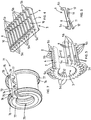
- Fig. 5 is shown another embodiment of a vibration-isolating insert.
- the same features are indicated with the same reference numerals as in the above described embodiments.
- the vibration isolating insert of Fig 5 has hook units 9 two opposing hooks 5a, 5b interconnected by a connecting bridge 8.
- the hook unit 9 is shown in Fig. 6 .
- the connecting bridge 8 is embedded in the vibration-isolating material of the strip 2.
- This embodiment can be manufactured by providing a mould for moulding a strip of vibration-isolating material, and positioning a plurality of said hook units in said mould at regular intervals. Then vibration-isolating material is injected in the mould whereby the connecting bridge 8 of said hook units 9 is at least partially embedded in the vibration-isolating material.
- the hook units 9 can be formed by injection moulding them of a plastics material.
- An alternative is to form the hook units 9 by punching them out of a sheet of a suitable material, in particular plastic, although also other materials are conceivable, such as composites or metal.
- the hook unit 9 in Fig. 6 has an additional feature compared to other hook units described in the above, which is that it furthermore includes two legs 11 connected with one end thereof to the bridge portion 8, preferably in a centre of the bridge portion 8.
- the legs 11 each have at another end a pipe engagement protrusion 12.
- the legs 11 are embedded in the vibration-isolating material of the strip as becomes clear from Fig. 5 .
- the pipe engagement protrusions 12 protrude outside the vibration-isolating material at the pipe facing side 3 of the strip 2 as can be seen in Fig. 5 .
- the pipe engagement protrusions 12 have the same function as the longitudinal ribs on the inner side of the strip 2 in Figs 1 and 2 . Because the material of the protrusions 12 is harder than the vibration-isolating material, the friction between a pipe surface and the insert is reduced. Thereby the pipe can during installation slide easier through the insert.
- Fig. 7 is shown another vibration isolating insert 71 for a pipe clip.
- the vibration-isolating insert 71 comprises an elongate strip 72 of vibration-isolating material and has a pipe facing side 73 and a pipe clip facing side 74.
- the vibration-isolating insert 72 has along each of the lateral edges at the pipe clip facing side a substantially L-shaped profile 75.
- the L-shaped profile has a first leg 76 extending in alignment with the lateral side 77 of the strip 72 and a second leg 78 extending from the first leg 76 in a transverse direction.
- the first leg 76 is made exclusively of vibration isolating material and the second leg 78 is made of a plastic material which is more rigid than the vibration-isolating material.
Description
- The present invention relates to a vibration-isolating insert for a pipe clip, the vibration-isolating insert being adapted to bear against an inner circumference of a substantially annular pipe clip body and ultimately - in use - to be positioned between the outer circumference of a pipe and the pipe clip body, the vibration-isolating insert comprising an elongate strip of vibration-isolating material and having a pipe facing side and a pipe clip facing side.
- A known problem with vibration-isolating inserts in pipe clips is that during installation of pipes, the pipe slides through the pipe clip which is not yet entirely tightened around the pipe. The friction between the pipe surface and the insert may cause the insert to be pulled out of the pipe clip body.
-
EP 0413 883 A1 discloses a vibration-isolating insert formed as a profiled strip having substantially a U-shaped cross section. The profiled strip has a base strip made of a soft material and lateral wall portions that in use extend beyond the lateral edges of the pipe clip body. The respective lateral wall portions have an end portion bent inwardly to grip around respective lateral edges of the pipe clip body. The lateral wall portions are made of a harder material than the base strip so as to provide a better anchoring of the vibration-isolating insert in the pipe clip body. A disadvantage of this known vibration-isolating insert is that it has a high resistance to bending and it is difficult to adapt to the annular shape of the pipe clip, especially when pipe clips for smaller pipe diameters are to be assembled.DE 102007052701 A1 respectivelyEP 2133617 A1 discloses another vibration isolating insert for a pipe clip. - The present invention has for an object to provide a vibration isolating insert that overcomes or at least mitigates the mentioned disadvantage.
- This object is achieved by a vibration-isolating insert for a pipe clip, the vibration-isolating insert being adapted to bear against an inner circumference of a substantially annular pipe clip body and ultimately - in use - to be positioned between the outer circumference of a pipe and the pipe clip body, the vibration-isolating insert comprising an elongate strip of vibration-isolating material which has a pipe facing side and a pipe clip facing side, said strip of vibration-isolating material having adjacent either lateral edge thereof a series of discrete exposed hooks of plastics material which is more rigid than the vibration-isolating material, the hooks protruding relative to the pipe clip facing side of the strip of vibration-isolating material.
- The respective series of discrete hooks along the lateral edge portions provide retaining means that in use engage around respective edges of the pipe clip body. The bending resistance in longitudinal direction is determined by the continuous part of the insert. Because the hooks are discrete items positioned at regular intervals, they have no or only a relatively small contribution to the bending resistance in the longitudinal direction of the insert. The bending resistance of the insert is thus mainly determined by the strip of vibration isolating insert, which is made from a "softer" material such as rubber or a thermoplastic elastomer.
- In a possible embodiment two opposing hooks located on each of the lateral edge portions are interconnected by a connecting bridge of plastics material to form an integral hook unit. Preferably the integral hook unit is formed in one piece. The connecting bridge provides rigidity in the transverse direction between the two opposing hooks. Thereby the insert in the pipe clip is retained more secure in the pipe clip body.
- In a possible embodiment said integral hook unit is interconnected with a previous and/or a subsequent integral hook unit by a flexible carrier strip, said carrier strip being attached to said strip of vibration-isolating material. Preferably the carrier strip is formed in one piece with the connecting bridges of said hook units.
- The carrier strip is preferably substantially thinner than the connecting bridges. Thereby the low bending resistance of the vibration-isolating insert is warranted.
- In a possible embodiment said connection bridge of said unit is, at least partly embedded in the vibration-isolating material of the strip. This results in that the hook unit is anchored firmly in the strip of vibration-isolating material.
- In a particular embodiment the hook unit furthermore includes two legs connected with one end thereof to the bridge portion, preferably in a centre of the bridge portion, said legs each having at another end a pipe engagement protrusion, wherein the legs are embedded in the vibration-isolating material of the strip and the pipe engagement protrusions protrude outside the vibration-isolating material at the pipe facing side of the strip.
- According to another aspect the invention relates to a vibration-isolating insert for a pipe clip, the vibration-isolating insert being adapted to bear against an inner circumference of a substantially annular pipe clip body and ultimately - in use - to be positioned between the outer circumference of a pipe and the pipe clip body, the vibration-isolating insert comprising an elongate strip of vibration-isolating material and having a pipe facing side and a pipe clip facing side, wherein the vibration-isolating insert has along each of the lateral edges at the pipe clip facing side a substantially L-shaped profile, the L-shaped profile having a first leg extending in alignment with the lateral side of the strip and a second leg extending from the first leg in a transverse direction, wherein the first leg is made of vibration isolating material and the second leg is made of a plastic material which is more rigid than the vibration-isolating material.
- The insert according to this aspect has an L-shaped profile to grip around the pipe clip body, wherein the first leg of the L-shaped profile is, according to the invention, made exclusively of vibration isolating material and the second leg, is exclusively made of a more rigid plastic material. Thereby this vibration-isolating insert has a lower bending resistance than the known vibration-isolating insert of
EP 0413 883 A1 , while the retaining force is increased with regard to inserts which are entirely made of vibration-isolating material. - The invention also relates to a pipe clip comprising an annular pipe clip body and a vibration-isolating insert as described in the above, wherein the vibration-isolating insert is arranged on the radially seen inner side of the pipe clip body.
- The vibration-isolating insert, may bemade by a method, which is currently not claimed. The vibration-isolating insert is adapted to bear against an inner circumference of a substantially annular pipe clip body and ultimately - in use - to be positioned between the outer circumference of a pipe and the pipe clip body. The method includies the following steps:
- coextruding a continuous strip of vibration-isolating material, and a continuous strip of plastics material which is more rigid than the vibration-isolating material, wherein the strip of plastics material has a profiled section with hooks formed at the lateral sides,
- removing a transverse section of the strip of plastics material at constant intervals. The transverse section of the strip of plastics material may advantageously be removed by punching. Another option is to remove the transverse section of the strip of plastics material by milling.
- The transverse section of the strip of plastics material may be removed entirely. Another option is that the transverse section is removed to such an extent that a film layer of said plastic material remains. The latter has the advantage that the integrity of the vibration isolating strip can be warranted. Furthermore a better attachment of the vibration-isolating strip and the plastic parts can be expected.
- Another method for manufacturing a vibration-isolating insert, is also disclosed. The method is currently not claimed The vibration-isolating insert is adapted to bear against an inner circumference of a substantially annular pipe clip body and ultimately - in use - to be positioned between the outer circumference of a pipe and the pipe clip body. The method indudies the following steps:
- extruding a continuous strip of plastics material, wherein the strip of plastics material has a profiled section with hooks formed at the lateral sides,
- removing a transverse section of the strip of plastics material at constant intervals to such an extent that a film layer of said plastic material remains whereby a carrier strip with hook units at constant intervals is formed,
- feed the carrier strip to an extrusion device and extrude a strip of vibration-isolating material to a back of the carrier strip, wherein the vibration-isolating material is less rigid than the plastics material.
- In this method the plastic part and the part made of vibration-isolating material, such as rubber or another elastomer, can be formed separately in separate moulds and then be brought to gether and fused or adhered to one another.
- Yet another method for manufacturing a vibration-isolating insert, is disclosed. This method is currently not claimed. The vibration-isolating insert is adapted to bear against an inner circumference of a substantially annular pipe clip body and ultimately - in use - to be positioned between the outer circumference of a pipe and the pipe clip body. The method including the following steps:
- forming hook units of plastics material, said hook units comprising two opposing hooks interconnected by a connecting bridge,
- providing a mould for moulding a strip of vibration-isolating material,
- positioning a plurality of said hook units in said mould at regular intervals,
- injecting vibration-isolating material in the mould whereby the connecting bridge of said hook units is at least partially embedded in the vibration-isolating material.
- According to this method the vibration-isolating insert is made by so called "insert moulding", wherein the hook units are the inserts and the vibration-isolating material is injected around the inserts in the mould.
- In an example of the method the hook units are formed by injection moulding them of a plastics material. Another option is to form the hook units by punching them out of a sheet. It is conceivable to punch the hook units from another suitable material than plastic, e.g. metal, a composite or a paper based sheet.
- The invention will be described in more detail in the following description with reference to the drawing, in which:
-
Fig. 1 shows a view in perspective of a possible embodiment of a vibration-isolating insert according to the invention, -
Fig. 2 shows a view in perspective of a pipe clip including the insert ofFig. 1 arranged around a pipe, -
Fig. 3 shows a view in perspective of another embodiment of a vibration-isolating insert according to the invention, -
Fig. 4 shows a view in perspective of yet another vibration-isolating insert in a straight strip form, -
Fig. 5 shows a view in perspective of yet another vibration-isolating insert according to the invention, -
Fig. 6 shows an insert used in the manufacturing of the insert ofFig. 5 , and -
Fig. 7 shows a view in perspective of another vibration-isolating insert. - In
Fig. 1 is illustrated the general idea of a vibration-isolating insert with hooks.Fig. 1 shows a vibration isolating insert 1 in a bent fashion. The vibration-isolating insert 1 is fitted in the bent fashion in a pipe clip body, but is produced in a straight fashion. The insert 1 comprises anelongate strip 2 of vibration-isolating material. Thestrip 2 has apipe facing side 3 and a pipeclip facing side 4. In the embodiment ofFig. 1 thepipe facing side 3 of thevibration isolating strip 2 is provided withlongitudinal ribs - Adjacent either lateral edge of the strip 2 a series of discrete exposed
hooks strip 2 of vibration isolating material to which they are attached and in some embodiments a thin plastic film as will be described below in relation toFig. 4 . "Exposed" means that the plastic hooks are not covered by or embedded in the vibration- isolating material. - The
hooks clip facing side 4 of thestrip 2 of vibration-isolating material. The plastic material of thehooks strip 2. - The vibration-isolating insert 1 is arranged in a
pipe clip body 26 of apipe clip 20 as is shown inFig. 2 . Such apipe clip body 26 has a substantially annular shape and is preferably made of metal. Thepipe clip body 26 hasend flanges pipe 100. The end flanges 22, 23 are tightened together by tightening means. The tightening means include amale fastening element 24, e.g. a screw and afemale fastening element 25, e.g. a nut, which in use cooperate to tighten theflanges pipe 100. - In use the pipe
clip facing side 4 of thestrip 2 bears against an inner circumference of thepipe clip body 26. In use the insert 1 is positioned between the outer circumference of apipe 100 and thepipe clip body 26. Thehooks pipe clip body 26. - The outer
longitudinal ribs 6 of the vibration-isolatingstrip 2 are provided with atip portion 13 that is made of a material of greater hardness than the vibration-isolating material of thestrip 2. Thereby the friction between the pipe surface and thetip portion 13 of theribs 6 is reduced. During installation of apipe 100 in thepipe clip 20, the pipe clip is not yet fully tensioned and the pipe can slide with respect to thepipe clip 20 to put it in the desired position. Theouter ribs 6 are preferably higher than theinner ribs 7, whereby the pipe surface will contact thetip portions 13 of the outer ribs. This makes movement between pipe and pipe clip insert 1 easier and reduces the risk of distortion of the insert 1, and even removal of the insert 1 from thepipe clip 20. When thepipe clip 20 is tightened around the pipe, theother ribs 7 and the further parts of thepipe facing side 3 come into engagement with the pipe surface. - In
Fig. 3 an advantageous embodiment of a vibration-isolating insert according to the invention is shown. The general structure is the same as inFig. 1 and the same features are thus indicated by the same reference numerals. - In the embodiment of
Fig. 3 two opposinghooks bridge 8 of plastics material to form anintegral hook unit 9. Theconnection bridge 8 of saidunit 9 is, at least partly embedded in the vibration-isolating material of thestrip 2. - The
hook units 9 can be formed of plastics material by a suitable method. The hook units can for example be formed by injection moulding. Alternatively the hook units may be punched out of a plastic sheet. Another possibility is to form a profiled section by a continuous process such as extrusion, and then cut ofhook units 9 from the profiled section. - In an example of the method a number of
hook units 9 is positioned in a mould for moulding a strip of vibration-isolating material. Thehook units 9 are positioned in the mould at regular intervals. Then vibration-isolating material is injected in the mould to form astrip 2 of vibration-isolating material whereby the connectingbridge 8 of saidhook units 9 is at least partially embedded in the vibration-isolating material. - In
Fig. 4 a further embodiment of a vibration-isolating insert is shown. In this figure the same features are indicated with the same reference numerals as in embodiments ofFigs 1-3 and for a description of these features is referred to the above. - The embodiment of the vibration-isolating insert of
Fig. 4 is shown in a straight fashion. Evidently it can be bent to fit it in a pipe clip body as is illustrated inFig. 2 . - The embodiment of
Fig. 4 hashook units 9 each comprising ahook bridge 8. Theconsecutive hook units 9, that, seen in the longitudinal direction of the insert, are located at a mutual distance to each other, are interconnected by acarrier strip 10. Thecarrier strip 10 is in a preferred embodiment a plastic film which is formed in one piece with the hook units. - The
integral carrier strip 10 with thehook units 9 can be formed by extruding a continuous strip of plastics material, wherein the strip of plastics material has a profiled section with hooks formed at the lateral sides. Next a transverse section of the strip of plastics material is removed at constant intervals to such an extent that a film layer of said plastic material remains. Thereby acarrier strip 10 withhook units 9 at constant intervals is formed. - The transverse section of the strip of plastics material may be removed by punching, or by milling.
- The transverse section is removed to such an extent that a film layer of said plastic material remains.
- The
carrier strip 10 with theintegral hook units 9 can be fed to an extrusion device. In the extrusion device a strip of vibration-isolating material, that is less rigid than the plastics material, is extruded to a back of thecarrier strip 10, i.e. the side opposite the side where thehook units 9 are formed. - Alternatively a continuous strip of vibration-isolating material, and a continuous strip of plastics material which is more rigid than the vibration-isolating material are coextruded, wherein the strip of plastics material has a profiled section with hooks formed at the lateral sides. After the coextruded strip is cooled sufficiently a transverse section of the strip of plastics material at constant intervals is removed, thereby forming the hook units.
- In this latter method it is possible to remove the transverse section to such an extent that a film layer of said plastic material remains, but it is also possible to remove the entire transverse section. In the latter case the
hook units 9 are not connected by a plastic film. - It is also conceivable that a
carrier strip 10 withintegral hook units 9 and astrip 2 of vibration-isolating material are formed separately and are then joined by a suitable joining method, e.g. by means of an adhesive, or fusing the materials by heating them and then joining them. - It is also conceivable that the
carrier strip 10 withintegral hook units 9 is not made in one piece but is assembled fromhook units 9 and a carrier strip from suitable carrier material, which may be different from the plastic material from thehook units 9. As a carrier material could for example be used a woven material, e.g. a woven fabric. - In
Fig. 5 is shown another embodiment of a vibration-isolating insert. The same features are indicated with the same reference numerals as in the above described embodiments. - The vibration isolating insert of
Fig 5 hashook units 9 two opposinghooks bridge 8. Thehook unit 9 is shown inFig. 6 . The connectingbridge 8 is embedded in the vibration-isolating material of thestrip 2. - This embodiment can be manufactured by providing a mould for moulding a strip of vibration-isolating material, and positioning a plurality of said hook units in said mould at regular intervals. Then vibration-isolating material is injected in the mould whereby the connecting
bridge 8 of saidhook units 9 is at least partially embedded in the vibration-isolating material. - The
hook units 9 can be formed by injection moulding them of a plastics material. An alternative is to form thehook units 9 by punching them out of a sheet of a suitable material, in particular plastic, although also other materials are conceivable, such as composites or metal. - The
hook unit 9 inFig. 6 has an additional feature compared to other hook units described in the above, which is that it furthermore includes twolegs 11 connected with one end thereof to thebridge portion 8, preferably in a centre of thebridge portion 8. Thelegs 11 each have at another end apipe engagement protrusion 12. Thelegs 11 are embedded in the vibration-isolating material of the strip as becomes clear fromFig. 5 . Thepipe engagement protrusions 12 protrude outside the vibration-isolating material at thepipe facing side 3 of thestrip 2 as can be seen inFig. 5 . - The
pipe engagement protrusions 12 have the same function as the longitudinal ribs on the inner side of thestrip 2 inFigs 1 and 2 . Because the material of theprotrusions 12 is harder than the vibration-isolating material, the friction between a pipe surface and the insert is reduced. Thereby the pipe can during installation slide easier through the insert. - In
Fig. 7 is shown anothervibration isolating insert 71 for a pipe clip. The vibration-isolatinginsert 71 comprises anelongate strip 72 of vibration-isolating material and has apipe facing side 73 and a pipe clip facing side 74. The vibration-isolatinginsert 72 has along each of the lateral edges at the pipe clip facing side a substantially L-shapedprofile 75. The L-shaped profile has afirst leg 76 extending in alignment with thelateral side 77 of thestrip 72 and asecond leg 78 extending from thefirst leg 76 in a transverse direction. Thefirst leg 76 is made exclusively of vibration isolating material and thesecond leg 78 is made of a plastic material which is more rigid than the vibration-isolating material.
Claims (10)
- Vibration-isolating insert (1) for a pipe clip, the vibration-isolating insert being adapted to bear against an inner circumference of a substantially annular pipe clip body and ultimately- in use - to be positioned between an outer circumference of a pipe and the pipe clip body, the vibration-isolating insert (1) comprising an elongate strip (2) of vibration-isolating material which has a pipe facing side (3) and a pipe clip facing side (4), characterized by said strip (2) of vibration-isolating material having adjacent either lateral edge thereof a series of discrete exposed hooks (5a, 5b) of plastics material which is more rigid than the vibration-isolating material, the hooks (5a, 5b) protruding relative to the pipe clip facing side (3) of the strip (2) of vibration-isolating material.
- Vibration-isolating insert according to claim 1, wherein two opposing hooks (5a, 5b) of the series of discrete exposed hooks located at each of the lateral edges are interconnected by a connecting bridge (8) of plastics material to form an integral hook unit (9).
- Vibration-isolating insert according to claim 2, wherein said integral hook unit (9) is formed in one piece.
- Vibration-isolating insert according to claim 2 or 3, wherein said integral hook unit (9) is interconnected with a previous and/or a subsequent integral hook unit (9) by a flexible carrier strip (10), said carrier strip (10) being attached to said strip (2) of vibration-isolating material.
- Vibration-isolating insert according to claim 4, wherein the carrier strip (10) is formed in one piece with the connecting bridges (8) of said hook units (9).
- Vibration-isolating insert according to claim 4, wherein the carrier strip (10) is substantially thinner than the connecting bridges (8).
- Vibration-isolating insert according to claim 2 or 3, wherein said connecting bridge (8) of said hook unit (9) is, at least partly embedded in the vibration-isolating material of the strip (2).
- Vibration-isolating insert according to claim 7, wherein the hook unit (9) furthermore includes two legs (11) connected with one end thereof to the bridge portion (8), preferably in a centre of the bridge portion (8), said legs (11) each having at another end a pipe engagement protrusion (12), wherein the legs (11) are embedded in the vibration-isolating material of the strip (2) and the pipe engagement protrusions (12) protrude outside the vibration-isolating material at the pipe facing side (3) of the strip (2).
- Vibration-isolating insert (71) for a pipe clip, the vibration-isolating insert (71) being adapted to bear against an inner circumference of a substantially annular pipe clip body and ultimately - in use - to be positioned between an outer circumference of a pipe and the pipe clip body, the vibration-isolating insert comprising an elongate strip (72) of vibration-isolating material and having a pipe facing side (73) and a pipe clip facing side (74), wherein the vibration-isolating insert (71) has along each of the lateral edges at the pipe clip facing side (74) a substantially L-shaped profile (75), the L-shaped profile (75) having a first leg (76) extending in alignment with the lateral side (77) of the strip and a second leg (78) extending from the first leg (76) in a transverse direction, characterized in that the first leg (76) is exclusively made of vibration isolating material and the second leg (78) is made of a plastic material which is more rigid than the vibration-isolating material.
- Pipe clip comprising an annular pipe clip body and a vibration-isolating insert (1, 71) according to any one of the preceding claims, wherein the vibration-isolating insert is arranged on the radially seen inner side of the pipe clip body.
Priority Applications (1)
| Application Number | Priority Date | Filing Date | Title |
|---|---|---|---|
| PL15791786T PL3204681T3 (en) | 2014-10-08 | 2015-09-21 | Vibration isolating insert for a pipe clip |
Applications Claiming Priority (2)
| Application Number | Priority Date | Filing Date | Title |
|---|---|---|---|
| NL2013596A NL2013596B1 (en) | 2014-10-08 | 2014-10-08 | Vibration isolating insert for a pipe clip and method for manufacturing such an insert. |
| PCT/NL2015/050656 WO2016056895A2 (en) | 2014-10-08 | 2015-09-21 | Vibration isolating insert for a pipe clip and method for manufacturing such an insert. |
Publications (2)
| Publication Number | Publication Date |
|---|---|
| EP3204681A2 EP3204681A2 (en) | 2017-08-16 |
| EP3204681B1 true EP3204681B1 (en) | 2019-08-21 |
Family
ID=52146623
Family Applications (1)
| Application Number | Title | Priority Date | Filing Date |
|---|---|---|---|
| EP15791786.5A Active EP3204681B1 (en) | 2014-10-08 | 2015-09-21 | Vibration isolating insert for a pipe clip |
Country Status (7)
| Country | Link |
|---|---|
| US (1) | US10317002B2 (en) |
| EP (1) | EP3204681B1 (en) |
| CN (1) | CN106794613B (en) |
| ES (1) | ES2745535T3 (en) |
| NL (1) | NL2013596B1 (en) |
| PL (1) | PL3204681T3 (en) |
| WO (1) | WO2016056895A2 (en) |
Families Citing this family (2)
| Publication number | Priority date | Publication date | Assignee | Title |
|---|---|---|---|---|
| NL2017895B1 (en) * | 2016-11-30 | 2018-06-11 | Walraven Holding Bv J Van | Vibration isolating insert for a pipe clip |
| AU2019280452A1 (en) * | 2018-06-06 | 2020-12-17 | Abey Australia Pty. Ltd. | Damping extrusions |
Family Cites Families (6)
| Publication number | Priority date | Publication date | Assignee | Title |
|---|---|---|---|---|
| DE8910177U1 (en) * | 1989-08-25 | 1989-12-28 | Poppe & Co Giessener Gummiwarenfabrik Gmbh & Co Kg, 6300 Giessen, De | |
| US5018768A (en) * | 1990-07-19 | 1991-05-28 | Quikcoup, Incorporated | Pipe coupling hinge |
| US6226933B1 (en) * | 1999-08-10 | 2001-05-08 | Robert S. Nelson | Apparatus and method for enhancing the survivability of exposed structures |
| DE59912176D1 (en) * | 1999-11-19 | 2005-07-21 | Maag Pump Systems Textron Ag Z | Device with a magnetic coupling and use of the same for a gear pump |
| NL1032064C2 (en) * | 2006-06-27 | 2008-01-02 | Walraven Holding Bv J Van | Pipe bracket with vibration isolating layer. |
| DE102007052701A1 (en) * | 2007-11-06 | 2009-05-07 | Fischerwerke Gmbh & Co. Kg | Flexible insert e.g. profiled strip, for use as intermediate layer between pipe clamp and pipe, has longitudinal edges with reinforcement which stabilizes longitudinal edges against unintentional expanding of hook-shaped cross section |
-
2014
- 2014-10-08 NL NL2013596A patent/NL2013596B1/en not_active IP Right Cessation
-
2015
- 2015-09-21 CN CN201580054482.1A patent/CN106794613B/en active Active
- 2015-09-21 PL PL15791786T patent/PL3204681T3/en unknown
- 2015-09-21 US US15/517,649 patent/US10317002B2/en active Active
- 2015-09-21 ES ES15791786T patent/ES2745535T3/en active Active
- 2015-09-21 EP EP15791786.5A patent/EP3204681B1/en active Active
- 2015-09-21 WO PCT/NL2015/050656 patent/WO2016056895A2/en active Application Filing
Non-Patent Citations (1)
| Title |
|---|
| None * |
Also Published As
| Publication number | Publication date |
|---|---|
| US10317002B2 (en) | 2019-06-11 |
| CN106794613A (en) | 2017-05-31 |
| CN106794613B (en) | 2019-08-16 |
| WO2016056895A3 (en) | 2016-06-02 |
| PL3204681T3 (en) | 2020-03-31 |
| NL2013596B1 (en) | 2016-10-04 |
| US20180003327A1 (en) | 2018-01-04 |
| ES2745535T3 (en) | 2020-03-02 |
| WO2016056895A2 (en) | 2016-04-14 |
| EP3204681A2 (en) | 2017-08-16 |
Similar Documents
| Publication | Publication Date | Title |
|---|---|---|
| US7435904B2 (en) | Wiring harness clip and method of making same from an extrudable blank | |
| EP2255944A3 (en) | Male surface fastener member for use in a cushion body mold and manufacturing method thereof | |
| EP2032887B1 (en) | Pipe clip with vibration-isolating insert | |
| KR102208725B1 (en) | Fastening tape with reinforced hooks | |
| EP3204681B1 (en) | Vibration isolating insert for a pipe clip | |
| US20220080642A1 (en) | Extruded fastener and method for making same | |
| US20120180270A1 (en) | Fastening system | |
| US20170326775A1 (en) | Longitudinal bead molding | |
| JP2004231167A (en) | Core metal insert for weather seal | |
| JP2003200791A (en) | Trim insert and trim | |
| EP1961890A1 (en) | A combined set comprising covering elements and attachment elements and a method for mounting said combined set | |
| WO2010034148A1 (en) | Fastener | |
| EP3548787B1 (en) | Vibration isolating insert for a pipe clip | |
| US10919461B2 (en) | Flexible members for sealing, baffling, or reinforcing | |
| US11685085B2 (en) | Tubular member sealing device | |
| EP2860437B1 (en) | Inlay for pipe clips | |
| EP2207449B1 (en) | A slide fastener and a method for its manufacture | |
| US20020063424A1 (en) | Pipe fitting for inside coated pipes and method for its installation | |
| US20210015218A1 (en) | Touch fastener part | |
| US20120080431A1 (en) | Anchor rail with pull strip | |
| US20060141229A1 (en) | Strand-shaped flexible profile, and method for its production |
Legal Events
| Date | Code | Title | Description |
|---|---|---|---|
| STAA | Information on the status of an ep patent application or granted ep patent |
Free format text: STATUS: THE INTERNATIONAL PUBLICATION HAS BEEN MADE |
|
| PUAI | Public reference made under article 153(3) epc to a published international application that has entered the european phase |
Free format text: ORIGINAL CODE: 0009012 |
|
| STAA | Information on the status of an ep patent application or granted ep patent |
Free format text: STATUS: REQUEST FOR EXAMINATION WAS MADE |
|
| 17P | Request for examination filed |
Effective date: 20170425 |
|
| AK | Designated contracting states |
Kind code of ref document: A2 Designated state(s): AL AT BE BG CH CY CZ DE DK EE ES FI FR GB GR HR HU IE IS IT LI LT LU LV MC MK MT NL NO PL PT RO RS SE SI SK SM TR |
|
| AX | Request for extension of the european patent |
Extension state: BA ME |
|
| DAV | Request for validation of the european patent (deleted) | ||
| DAX | Request for extension of the european patent (deleted) | ||
| RIC1 | Information provided on ipc code assigned before grant |
Ipc: B29C 47/00 20060101ALI20181204BHEP Ipc: F16L 3/12 20060101ALI20181204BHEP Ipc: F16L 55/035 20060101AFI20181204BHEP Ipc: B29C 47/04 20060101ALI20181204BHEP Ipc: F16L 3/08 20060101ALI20181204BHEP |
|
| GRAP | Despatch of communication of intention to grant a patent |
Free format text: ORIGINAL CODE: EPIDOSNIGR1 |
|
| STAA | Information on the status of an ep patent application or granted ep patent |
Free format text: STATUS: GRANT OF PATENT IS INTENDED |
|
| INTG | Intention to grant announced |
Effective date: 20190118 |
|
| GRAJ | Information related to disapproval of communication of intention to grant by the applicant or resumption of examination proceedings by the epo deleted |
Free format text: ORIGINAL CODE: EPIDOSDIGR1 |
|
| STAA | Information on the status of an ep patent application or granted ep patent |
Free format text: STATUS: REQUEST FOR EXAMINATION WAS MADE |
|
| RIC1 | Information provided on ipc code assigned before grant |
Ipc: B29C 48/18 20190101ALI20190121BHEP Ipc: F16L 3/08 20060101ALI20190121BHEP Ipc: F16L 55/035 20060101AFI20190121BHEP Ipc: B29C 48/00 20190101ALI20190121BHEP Ipc: F16L 3/12 20060101ALI20190121BHEP |
|
| INTC | Intention to grant announced (deleted) | ||
| RIC1 | Information provided on ipc code assigned before grant |
Ipc: B29C 48/18 20190101ALI20190221BHEP Ipc: F16L 3/12 20060101ALI20190221BHEP Ipc: B29C 48/00 20190101ALI20190221BHEP Ipc: B29C 48/16 20190101ALI20190221BHEP Ipc: B29C 48/12 20190101ALI20190221BHEP Ipc: F16L 55/035 20060101AFI20190221BHEP Ipc: F16L 3/08 20060101ALI20190221BHEP |
|
| GRAP | Despatch of communication of intention to grant a patent |
Free format text: ORIGINAL CODE: EPIDOSNIGR1 |
|
| STAA | Information on the status of an ep patent application or granted ep patent |
Free format text: STATUS: GRANT OF PATENT IS INTENDED |
|
| INTG | Intention to grant announced |
Effective date: 20190404 |
|
| GRAS | Grant fee paid |
Free format text: ORIGINAL CODE: EPIDOSNIGR3 |
|
| GRAA | (expected) grant |
Free format text: ORIGINAL CODE: 0009210 |
|
| STAA | Information on the status of an ep patent application or granted ep patent |
Free format text: STATUS: THE PATENT HAS BEEN GRANTED |
|
| AK | Designated contracting states |
Kind code of ref document: B1 Designated state(s): AL AT BE BG CH CY CZ DE DK EE ES FI FR GB GR HR HU IE IS IT LI LT LU LV MC MK MT NL NO PL PT RO RS SE SI SK SM TR |
|
| REG | Reference to a national code |
Ref country code: GB Ref legal event code: FG4D |
|
| REG | Reference to a national code |
Ref country code: CH Ref legal event code: EP |
|
| REG | Reference to a national code |
Ref country code: DE Ref legal event code: R096 Ref document number: 602015036356 Country of ref document: DE |
|
| REG | Reference to a national code |
Ref country code: AT Ref legal event code: REF Ref document number: 1170157 Country of ref document: AT Kind code of ref document: T Effective date: 20190915 |
|
| REG | Reference to a national code |
Ref country code: IE Ref legal event code: FG4D |
|
| REG | Reference to a national code |
Ref country code: NL Ref legal event code: FP |
|
| REG | Reference to a national code |
Ref country code: LT Ref legal event code: MG4D |
|
| PG25 | Lapsed in a contracting state [announced via postgrant information from national office to epo] |
Ref country code: FI Free format text: LAPSE BECAUSE OF FAILURE TO SUBMIT A TRANSLATION OF THE DESCRIPTION OR TO PAY THE FEE WITHIN THE PRESCRIBED TIME-LIMIT Effective date: 20190821 Ref country code: NO Free format text: LAPSE BECAUSE OF FAILURE TO SUBMIT A TRANSLATION OF THE DESCRIPTION OR TO PAY THE FEE WITHIN THE PRESCRIBED TIME-LIMIT Effective date: 20191121 Ref country code: PT Free format text: LAPSE BECAUSE OF FAILURE TO SUBMIT A TRANSLATION OF THE DESCRIPTION OR TO PAY THE FEE WITHIN THE PRESCRIBED TIME-LIMIT Effective date: 20191223 Ref country code: BG Free format text: LAPSE BECAUSE OF FAILURE TO SUBMIT A TRANSLATION OF THE DESCRIPTION OR TO PAY THE FEE WITHIN THE PRESCRIBED TIME-LIMIT Effective date: 20191121 Ref country code: SE Free format text: LAPSE BECAUSE OF FAILURE TO SUBMIT A TRANSLATION OF THE DESCRIPTION OR TO PAY THE FEE WITHIN THE PRESCRIBED TIME-LIMIT Effective date: 20190821 Ref country code: HR Free format text: LAPSE BECAUSE OF FAILURE TO SUBMIT A TRANSLATION OF THE DESCRIPTION OR TO PAY THE FEE WITHIN THE PRESCRIBED TIME-LIMIT Effective date: 20190821 Ref country code: LT Free format text: LAPSE BECAUSE OF FAILURE TO SUBMIT A TRANSLATION OF THE DESCRIPTION OR TO PAY THE FEE WITHIN THE PRESCRIBED TIME-LIMIT Effective date: 20190821 |
|
| PG25 | Lapsed in a contracting state [announced via postgrant information from national office to epo] |
Ref country code: IS Free format text: LAPSE BECAUSE OF FAILURE TO SUBMIT A TRANSLATION OF THE DESCRIPTION OR TO PAY THE FEE WITHIN THE PRESCRIBED TIME-LIMIT Effective date: 20191221 Ref country code: LV Free format text: LAPSE BECAUSE OF FAILURE TO SUBMIT A TRANSLATION OF THE DESCRIPTION OR TO PAY THE FEE WITHIN THE PRESCRIBED TIME-LIMIT Effective date: 20190821 Ref country code: RS Free format text: LAPSE BECAUSE OF FAILURE TO SUBMIT A TRANSLATION OF THE DESCRIPTION OR TO PAY THE FEE WITHIN THE PRESCRIBED TIME-LIMIT Effective date: 20190821 Ref country code: GR Free format text: LAPSE BECAUSE OF FAILURE TO SUBMIT A TRANSLATION OF THE DESCRIPTION OR TO PAY THE FEE WITHIN THE PRESCRIBED TIME-LIMIT Effective date: 20191122 Ref country code: AL Free format text: LAPSE BECAUSE OF FAILURE TO SUBMIT A TRANSLATION OF THE DESCRIPTION OR TO PAY THE FEE WITHIN THE PRESCRIBED TIME-LIMIT Effective date: 20190821 |
|
| PGFP | Annual fee paid to national office [announced via postgrant information from national office to epo] |
Ref country code: ES Payment date: 20191220 Year of fee payment: 5 |
|
| REG | Reference to a national code |
Ref country code: ES Ref legal event code: FG2A Ref document number: 2745535 Country of ref document: ES Kind code of ref document: T3 Effective date: 20200302 |
|
| REG | Reference to a national code |
Ref country code: AT Ref legal event code: MK05 Ref document number: 1170157 Country of ref document: AT Kind code of ref document: T Effective date: 20190821 |
|
| PG25 | Lapsed in a contracting state [announced via postgrant information from national office to epo] |
Ref country code: TR Free format text: LAPSE BECAUSE OF FAILURE TO SUBMIT A TRANSLATION OF THE DESCRIPTION OR TO PAY THE FEE WITHIN THE PRESCRIBED TIME-LIMIT Effective date: 20190821 |
|
| PG25 | Lapsed in a contracting state [announced via postgrant information from national office to epo] |
Ref country code: RO Free format text: LAPSE BECAUSE OF FAILURE TO SUBMIT A TRANSLATION OF THE DESCRIPTION OR TO PAY THE FEE WITHIN THE PRESCRIBED TIME-LIMIT Effective date: 20190821 Ref country code: AT Free format text: LAPSE BECAUSE OF FAILURE TO SUBMIT A TRANSLATION OF THE DESCRIPTION OR TO PAY THE FEE WITHIN THE PRESCRIBED TIME-LIMIT Effective date: 20190821 Ref country code: EE Free format text: LAPSE BECAUSE OF FAILURE TO SUBMIT A TRANSLATION OF THE DESCRIPTION OR TO PAY THE FEE WITHIN THE PRESCRIBED TIME-LIMIT Effective date: 20190821 Ref country code: DK Free format text: LAPSE BECAUSE OF FAILURE TO SUBMIT A TRANSLATION OF THE DESCRIPTION OR TO PAY THE FEE WITHIN THE PRESCRIBED TIME-LIMIT Effective date: 20190821 |
|
| PG25 | Lapsed in a contracting state [announced via postgrant information from national office to epo] |
Ref country code: SM Free format text: LAPSE BECAUSE OF FAILURE TO SUBMIT A TRANSLATION OF THE DESCRIPTION OR TO PAY THE FEE WITHIN THE PRESCRIBED TIME-LIMIT Effective date: 20190821 Ref country code: CZ Free format text: LAPSE BECAUSE OF FAILURE TO SUBMIT A TRANSLATION OF THE DESCRIPTION OR TO PAY THE FEE WITHIN THE PRESCRIBED TIME-LIMIT Effective date: 20190821 Ref country code: IS Free format text: LAPSE BECAUSE OF FAILURE TO SUBMIT A TRANSLATION OF THE DESCRIPTION OR TO PAY THE FEE WITHIN THE PRESCRIBED TIME-LIMIT Effective date: 20200224 Ref country code: MC Free format text: LAPSE BECAUSE OF FAILURE TO SUBMIT A TRANSLATION OF THE DESCRIPTION OR TO PAY THE FEE WITHIN THE PRESCRIBED TIME-LIMIT Effective date: 20190821 Ref country code: SK Free format text: LAPSE BECAUSE OF FAILURE TO SUBMIT A TRANSLATION OF THE DESCRIPTION OR TO PAY THE FEE WITHIN THE PRESCRIBED TIME-LIMIT Effective date: 20190821 |
|
| REG | Reference to a national code |
Ref country code: CH Ref legal event code: PL |
|
| REG | Reference to a national code |
Ref country code: DE Ref legal event code: R097 Ref document number: 602015036356 Country of ref document: DE |
|
| PLBE | No opposition filed within time limit |
Free format text: ORIGINAL CODE: 0009261 |
|
| STAA | Information on the status of an ep patent application or granted ep patent |
Free format text: STATUS: NO OPPOSITION FILED WITHIN TIME LIMIT |
|
| PG2D | Information on lapse in contracting state deleted |
Ref country code: IS |
|
| PG25 | Lapsed in a contracting state [announced via postgrant information from national office to epo] |
Ref country code: IE Free format text: LAPSE BECAUSE OF NON-PAYMENT OF DUE FEES Effective date: 20190921 Ref country code: LU Free format text: LAPSE BECAUSE OF NON-PAYMENT OF DUE FEES Effective date: 20190921 Ref country code: CH Free format text: LAPSE BECAUSE OF NON-PAYMENT OF DUE FEES Effective date: 20190930 Ref country code: LI Free format text: LAPSE BECAUSE OF NON-PAYMENT OF DUE FEES Effective date: 20190930 |
|
| REG | Reference to a national code |
Ref country code: BE Ref legal event code: MM Effective date: 20190930 |
|
| 26N | No opposition filed |
Effective date: 20200603 |
|
| PG25 | Lapsed in a contracting state [announced via postgrant information from national office to epo] |
Ref country code: SI Free format text: LAPSE BECAUSE OF FAILURE TO SUBMIT A TRANSLATION OF THE DESCRIPTION OR TO PAY THE FEE WITHIN THE PRESCRIBED TIME-LIMIT Effective date: 20190821 Ref country code: BE Free format text: LAPSE BECAUSE OF NON-PAYMENT OF DUE FEES Effective date: 20190930 |
|
| PG25 | Lapsed in a contracting state [announced via postgrant information from national office to epo] |
Ref country code: CY Free format text: LAPSE BECAUSE OF FAILURE TO SUBMIT A TRANSLATION OF THE DESCRIPTION OR TO PAY THE FEE WITHIN THE PRESCRIBED TIME-LIMIT Effective date: 20190821 |
|
| PG25 | Lapsed in a contracting state [announced via postgrant information from national office to epo] |
Ref country code: HU Free format text: LAPSE BECAUSE OF FAILURE TO SUBMIT A TRANSLATION OF THE DESCRIPTION OR TO PAY THE FEE WITHIN THE PRESCRIBED TIME-LIMIT; INVALID AB INITIO Effective date: 20150921 Ref country code: MT Free format text: LAPSE BECAUSE OF FAILURE TO SUBMIT A TRANSLATION OF THE DESCRIPTION OR TO PAY THE FEE WITHIN THE PRESCRIBED TIME-LIMIT Effective date: 20190821 |
|
| REG | Reference to a national code |
Ref country code: ES Ref legal event code: FD2A Effective date: 20220117 |
|
| PG25 | Lapsed in a contracting state [announced via postgrant information from national office to epo] |
Ref country code: ES Free format text: LAPSE BECAUSE OF NON-PAYMENT OF DUE FEES Effective date: 20200922 |
|
| PG25 | Lapsed in a contracting state [announced via postgrant information from national office to epo] |
Ref country code: MK Free format text: LAPSE BECAUSE OF FAILURE TO SUBMIT A TRANSLATION OF THE DESCRIPTION OR TO PAY THE FEE WITHIN THE PRESCRIBED TIME-LIMIT Effective date: 20190821 |
|
| PGFP | Annual fee paid to national office [announced via postgrant information from national office to epo] |
Ref country code: NL Payment date: 20220926 Year of fee payment: 8 Ref country code: GB Payment date: 20220923 Year of fee payment: 8 |
|
| PGFP | Annual fee paid to national office [announced via postgrant information from national office to epo] |
Ref country code: PL Payment date: 20220913 Year of fee payment: 8 Ref country code: FR Payment date: 20220923 Year of fee payment: 8 |
|
| PGFP | Annual fee paid to national office [announced via postgrant information from national office to epo] |
Ref country code: IT Payment date: 20220926 Year of fee payment: 8 |
|
| PGFP | Annual fee paid to national office [announced via postgrant information from national office to epo] |
Ref country code: DE Payment date: 20230919 Year of fee payment: 9 |