EP3548787B1 - Vibration isolating insert for a pipe clip - Google Patents
Vibration isolating insert for a pipe clip Download PDFInfo
- Publication number
- EP3548787B1 EP3548787B1 EP17817272.2A EP17817272A EP3548787B1 EP 3548787 B1 EP3548787 B1 EP 3548787B1 EP 17817272 A EP17817272 A EP 17817272A EP 3548787 B1 EP3548787 B1 EP 3548787B1
- Authority
- EP
- European Patent Office
- Prior art keywords
- vibration isolating
- framework
- pipe
- pipe clip
- insert
- Prior art date
- Legal status (The legal status is an assumption and is not a legal conclusion. Google has not performed a legal analysis and makes no representation as to the accuracy of the status listed.)
- Active
Links
- 239000000463 material Substances 0.000 claims description 35
- 230000015572 biosynthetic process Effects 0.000 claims description 27
- 238000005755 formation reaction Methods 0.000 claims description 27
- 230000003014 reinforcing effect Effects 0.000 claims description 20
- 229920001971 elastomer Polymers 0.000 claims description 4
- 238000001125 extrusion Methods 0.000 claims description 4
- 239000000806 elastomer Substances 0.000 claims description 3
- 238000004519 manufacturing process Methods 0.000 claims description 3
- 238000000034 method Methods 0.000 claims description 2
- 239000013536 elastomeric material Substances 0.000 description 6
- 239000002184 metal Substances 0.000 description 6
- 238000009434 installation Methods 0.000 description 5
- 230000002787 reinforcement Effects 0.000 description 5
- 238000005452 bending Methods 0.000 description 3
- 239000002131 composite material Substances 0.000 description 3
- 238000001746 injection moulding Methods 0.000 description 3
- 230000000694 effects Effects 0.000 description 1
Images


Classifications
-
- F—MECHANICAL ENGINEERING; LIGHTING; HEATING; WEAPONS; BLASTING
- F16—ENGINEERING ELEMENTS AND UNITS; GENERAL MEASURES FOR PRODUCING AND MAINTAINING EFFECTIVE FUNCTIONING OF MACHINES OR INSTALLATIONS; THERMAL INSULATION IN GENERAL
- F16L—PIPES; JOINTS OR FITTINGS FOR PIPES; SUPPORTS FOR PIPES, CABLES OR PROTECTIVE TUBING; MEANS FOR THERMAL INSULATION IN GENERAL
- F16L55/00—Devices or appurtenances for use in, or in connection with, pipes or pipe systems
- F16L55/02—Energy absorbers; Noise absorbers
- F16L55/033—Noise absorbers
- F16L55/035—Noise absorbers in the form of specially adapted hangers or supports
-
- B—PERFORMING OPERATIONS; TRANSPORTING
- B29—WORKING OF PLASTICS; WORKING OF SUBSTANCES IN A PLASTIC STATE IN GENERAL
- B29C—SHAPING OR JOINING OF PLASTICS; SHAPING OF MATERIAL IN A PLASTIC STATE, NOT OTHERWISE PROVIDED FOR; AFTER-TREATMENT OF THE SHAPED PRODUCTS, e.g. REPAIRING
- B29C48/00—Extrusion moulding, i.e. expressing the moulding material through a die or nozzle which imparts the desired form; Apparatus therefor
- B29C48/16—Articles comprising two or more components, e.g. co-extruded layers
-
- B—PERFORMING OPERATIONS; TRANSPORTING
- B29—WORKING OF PLASTICS; WORKING OF SUBSTANCES IN A PLASTIC STATE IN GENERAL
- B29C—SHAPING OR JOINING OF PLASTICS; SHAPING OF MATERIAL IN A PLASTIC STATE, NOT OTHERWISE PROVIDED FOR; AFTER-TREATMENT OF THE SHAPED PRODUCTS, e.g. REPAIRING
- B29C48/00—Extrusion moulding, i.e. expressing the moulding material through a die or nozzle which imparts the desired form; Apparatus therefor
- B29C48/03—Extrusion moulding, i.e. expressing the moulding material through a die or nozzle which imparts the desired form; Apparatus therefor characterised by the shape of the extruded material at extrusion
- B29C48/12—Articles with an irregular circumference when viewed in cross-section, e.g. window profiles
-
- F—MECHANICAL ENGINEERING; LIGHTING; HEATING; WEAPONS; BLASTING
- F16—ENGINEERING ELEMENTS AND UNITS; GENERAL MEASURES FOR PRODUCING AND MAINTAINING EFFECTIVE FUNCTIONING OF MACHINES OR INSTALLATIONS; THERMAL INSULATION IN GENERAL
- F16L—PIPES; JOINTS OR FITTINGS FOR PIPES; SUPPORTS FOR PIPES, CABLES OR PROTECTIVE TUBING; MEANS FOR THERMAL INSULATION IN GENERAL
- F16L3/00—Supports for pipes, cables or protective tubing, e.g. hangers, holders, clamps, cleats, clips, brackets
- F16L3/08—Supports for pipes, cables or protective tubing, e.g. hangers, holders, clamps, cleats, clips, brackets substantially surrounding the pipe, cable or protective tubing
- F16L3/12—Supports for pipes, cables or protective tubing, e.g. hangers, holders, clamps, cleats, clips, brackets substantially surrounding the pipe, cable or protective tubing comprising a member substantially surrounding the pipe, cable or protective tubing
- F16L3/123—Supports for pipes, cables or protective tubing, e.g. hangers, holders, clamps, cleats, clips, brackets substantially surrounding the pipe, cable or protective tubing comprising a member substantially surrounding the pipe, cable or protective tubing and extending along the attachment surface
- F16L3/1233—Supports for pipes, cables or protective tubing, e.g. hangers, holders, clamps, cleats, clips, brackets substantially surrounding the pipe, cable or protective tubing comprising a member substantially surrounding the pipe, cable or protective tubing and extending along the attachment surface the member being of metal, with or without an other layer of other material
Definitions
- the invention relates to a vibration isolating insert for a pipe clip, the vibration isolating insert being adapted to be arranged on a substantially annular pipe clip body and ultimately - in use - to be positioned between the outer surface of a pipe and the pipe clip body.
- the vibration isolating insert comprises an elongate strip, said strip having a pipe facing side, which in use faces the outer surface of the pipe, and opposite thereto a pipe clip facing side, which in use faces an inner side of the pipe clip body.
- the vibration isolating insert furthermore comprises gripping formations connected to the strip at lateral side portions thereof and extending towards the pipe clip facing side and in use grip over the respective lateral edges of the pipe clip body.
- the vibration isolating insert comprises a framework and a vibration isolating lining made of a softer material different from the material of the framework.
- EP 2 133 617 discloses a vibration isolating insert for a pipe clip.
- This known insert has a metal reinforcing profile embedded in vibration isolating lining.
- the metal reinforcing profile is made of sheet metal.
- longitudinally distributed cutouts have to be made from the lateral side towards the centre.
- This known insert has the disadvantage that it is complex to manufacture. In particular making the metal reinforcing profile is labour-intensive.
- the present invention has for an object to provide a reinforced vibration isolating insert which is more efficiently manufactured.
- a vibration isolating insert according to the preamble of claim 1, wherein the framework is a profiled section element formed of a polymeric material, said framework comprising a strip shaped web, that reinforces the elongate strip, and lateral reinforcing members connected to the web on either lateral side of the web and reinforcing the gripping formations, and wherein the framework furthermore comprises at least one living hinge defining a pivot axis parallel to the longitudinal axis of the insert and allowing at least one of the gripping formations to swivel around said pivot axis to increase and decrease the distance between the gripping formations during arrangement of the insert on a pipe clip body.
- the vibration isolating insert according to the invention is preferably made by extrusion of a profile, wherein the framework and the lining are co-extruded from two different polymeric materials, and wherein the extruded profile is cut to length to fit in the pipe clip body.
- vibration isolating insert according to the invention by injection moulding, in particular 2K injection moulding.
- the vibration isolating insert according to the invention provides through the framework a relatively stiff insert that is able to withstand forces due to shifting of a pipe through the pipe clip during installation.
- the film hinges provide enough flexibility in the insert such that the insert can be easily arranged in a pipe clip.
- the lateral reinforcing members are each pivotably connected to the web by living hinges formed at the lateral sides of the web. This feature allows that the strip with the web can remain undeformed, while the gripping formation with their respective lateral reinforcing members can swivel outwardly so as to create enough space to insert the pipe clip body between the gripping formations.
- the vibration isolating lining is made of a polymeric material that is softer than the polymeric material of which the framework is made.
- the vibration isolating lining is made of an elastomeric material.
- the framework is made of an elastomeric material.
- This elastomeric material is harder and stiffer than the material of which the vibration isolating lining is made.
- Such an elastomeric framework provides enough flexibility to arrange the insert in a substantially annular form in a pipe clip, without the need to provide cut outs in the web of the framework to allow bending, while at the same time the framework provides sufficient structural stiffness and hardness to the insert to resist deformation due to installation of a pipe in the pipe clips in which these inserts are arranged.
- PVC polyvinyl styrene
- the framework comprises a longitudinal rib formed on the pipe facing side of each lateral reinforcing member.
- the longitudinal rib which forms an integral part of the framework provides a lever connected to the gripping formation, which lever can be used to pivot the gripping formation outwards and inwards.
- the longitudinal ribs can be pinched towards each other such that the gripping formations are pivoted outwardly whereby more space between the gripping formations is created.
- the gripping formations can then be moved beyond the lateral edges of the pipe clip body after which the gripping formations can move inwardly again to grip around the lateral edges of the pipe clip body.
- one or more longitudinal intermediate ribs made of the softer lining material are formed on the pipe facing side of the strip between the longitudinal ribs on the lateral reinforcing members.
- the intermediate ribs Preferably have a height smaller than the ribs on the lateral reinforcing members.
- the pipe clip facing side of the framework is entirely covered with the softer lining material. This ensures that the pipe clip body, which is usually a metal part, is only in contact with the softer lining material. Thereby vibrations that are possibly transferred from the pipe to the harder and more rigid framework of the insert, will not be transferred to the pipe clip body, or vice versa.
- the invention also relates to a method for manufacturing a vibration isolating insert according to claim 1, wherein the insert is made by extrusion of a profile, wherein the framework and the lining are co-extruded from two different polymeric materials, and wherein the extruded profile is cut to length to fit in the pipe clip body.
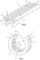
- Fig. 1 a vibration isolating insert 1 for a pipe clip in a straight unloaded state.
- the vibration isolating insert 1 in this particular embodiment is a composite profiled sectioned element made of two different polymeric materials.
- Fig. 2 the vibration isolating insert 1 is shown in a loaded bent state in which it is arranged in a pipe clip body.
- the insert 1 comprises an elongate strip 9 which has a pipe facing side 10, which in use faces the outer surface of a pipe, and opposite thereto a pipe clip facing side 11, which in use faces an inner side of a substantially annular pipe clip body.
- a profiled sectioned element 1 as is shown in Fig. 1 can be manufactured by co-extrusion. Another option is to form the profiled sectioned element by means of 2K injection moulding.
- the vibration isolating insert 1 is a composite body comprising a framework 2 and a vibration isolating lining 3.
- the framework 2 is flexible but is more rigid and harder than the vibration isolating lining 3.
- the material of the framework 2 has a lower friction coefficient than the material of the vibration isolating lining 3.
- the vibration isolating lining 3 may be formed of a soft elastomeric material such as rubber.
- the framework 2 is formed of an elastomeric material which is harder, and stiffer than the elastomeric material of the vibration isolating lining 3.
- an elastomeric framework provides enough flexibility to arrange the insert 1 in a substantially annular form in a pipe clip, without the need to provide cut outs in the web of the framework to allow bending.
- the framework 2 made of the harder elastomer provides sufficient structural stiffness and hardness to the insert to resist deformation due to installation of a pipe in the pipe clips in which these inserts are arranged.
- the framework 2 may be made of a plastic material.
- a PVC material is envisaged as a suitable plastic material, because it provides sufficient hardness and stiffness to the insert 1 to resist movement forces of the pipe with respect to the pipe clip.
- the framework 2 itself can be considered as a profiled section element formed of a polymeric material.
- the framework 2 generally has an H-shape that comprises a strip shaped web 21 and two lateral portions 22 that are located on the lateral sides of the web 21 and are connected thereto.
- the connection between the web 21 and the respective lateral portions 22 is formed by respective hinging portions 23, which are encircled in Fig. 3 .
- the hinging portions 23 extend longitudinally and include a living hinge 24 between the web 21 and the associated lateral portion 22.
- the living hinge 24 defines a pivot axis that extends in the longitudinal direction of the vibration isolating insert 1.
- the living hinge 24 is a thinner section in the framework 2 at the location where the lateral portion 22 adjoins the web 21.
- the vibration isolating insert 1 has gripping formations 4 which are configured and arranged to grip around the lateral edges 51 of the pipe clip body 5.
- the pipe clip body 5 is usually an annular strip-like body formed out of sheet metal.
- the pipe clip body 5 may comprise a single body which maybe arranged around a pipe and closed tightened with a screw.
- the pipe clip body 5 may just as well comprise two semi-circular pipe clip halves which can be tigthened with respect to each other and around a pipe with one or more screws.
- the gripping formations 4 include each a lateral reinforcement member 25 which form part of the lateral portions 22 of the framework 2.
- these lateral reinforcement members 25 are formed as an angled member.
- the inner side of the lateral reinforcement members 25 is lined with a vibration isolating material. Also the side of the web 21 and of the hinge portion 23 that in use faces the pipe clip body is lined with a vibration isolating material. Thus one integral vibration isolating lining 31 is formed covering the surfaces of web 21, hinges 24 and lateral reinforcement members 25 facing the pipe clip body. Thus the transfer of vibrations from the pipe clip body 5 to the framework 2 of the vibration isolating insert 1 and vice versa can be reduced considerably or even entirely prevented.
- each lateral reinforcing member 25 On the pipe facing side 10 of each lateral reinforcing member 25 a longitudinal rib 26 is formed.
- This longitudinal rib 26 may be formed with transverse cutouts 27 as is shown in Figs 1 and 2 . These cutouts 27 allow that the vibration isolating insert 1 can be bent (cf. Fig. 2 ) to conform to the (circular or semi-circular) shape of the pipe clip body 5.
- longitudinal ribs 32 Between the two longitudinal ribs 26 there are a number of longitudinal ribs 32 made of the softer lining material. In the example of Figs 1 - 3 there are two of such ribs 32 but this can be a different number. In the specific embodiment shown also these intermediate ribs 32 have transverse cutouts 33 to facilitate bending of the strip 1, but as the material of the intermediate ribs 32 is softer and less rigid than the material of the outer ribs 26, the provision of cutouts 33 in the softer ribs 32 is less imminent.
- the longitudinal ribs 26 have a function during the arrangement of the vibration isolating insert 1 in a pipe clip body:
- the longitudinal rib 26 acts as a lever arm which can be pushed inwards which is depicted in Fig. 4 by force arrow 40.
- a fitter may for example pinch the ribs 26 together.
- the gripping formations 25 pivot around the hinge 24, while the web 21 remains substantially flat and straight. Thereby the gripping formations 4 swivel outwards as can be seen in Fig. 4 .
- the gripping formations 4 can swivel outwards far enough such that the distance S1 between the extremities of the gripping formations exceeds the width S2 of the pipe clip body 5 (S1>S2) whereby the pipe clip body 5 fits between the flanges 41 of the gripping formations 4 and the pipe clip body 5 can be arranged against the lining 31 on the web 21.
- the insert 1 will return to its unloaded state (cf. Fig. 3 ) in which S1 ⁇ S2.
- the insert 1 will return to the unloaded state by the resiliency of the material of the framework 2 and of the vibration isolating lining 3, and the gripping formations 4 will grip around the lateral edges 51 of the pipe clip body 5.
- the pipe surface puts a pressure on the outer ribs 26, because these ribs 26 stand out above the intermediate ribs 32.
- the pipe surface is depicted schematically in Fig. 6 and indicated by reference numeral 6.
- the pressure force is indicated by arrows with reference numerals 42.
- the point of application of the pressure force 42 is located more on the inner side of the rib 26, whereby the rib 26 is forced outwardly as is shown in Fig. 6 .
- the lateral reinforcement member 25 pivots around the hinge 24 whereby the gripping formations 4 are forced inwardly.
- the pipe surface 6 will eventually come into engagement with the intermediate ribs 32 of the vibration isolating insert 1. Because the intermediate ribs 32 are made of a softer and better isolating material, the pipe is held more tightly by the pipe clip and the vibration isolating effect of the vibration isolating insert 1 is enhanced.
Description
- The invention relates to a vibration isolating insert for a pipe clip, the vibration isolating insert being adapted to be arranged on a substantially annular pipe clip body and ultimately - in use - to be positioned between the outer surface of a pipe and the pipe clip body. The vibration isolating insert comprises an elongate strip, said strip having a pipe facing side, which in use faces the outer surface of the pipe, and opposite thereto a pipe clip facing side, which in use faces an inner side of the pipe clip body. The vibration isolating insert furthermore comprises gripping formations connected to the strip at lateral side portions thereof and extending towards the pipe clip facing side and in use grip over the respective lateral edges of the pipe clip body. The vibration isolating insert comprises a framework and a vibration isolating lining made of a softer material different from the material of the framework.
-
EP 2 133 617 - The present invention has for an object to provide a reinforced vibration isolating insert which is more efficiently manufactured.
- This object is achieved by a vibration isolating insert according to the preamble of
claim 1, wherein the framework is a profiled section element formed of a polymeric material, said framework comprising a strip shaped web, that reinforces the elongate strip, and lateral reinforcing members connected to the web on either lateral side of the web and reinforcing the gripping formations, and wherein the framework furthermore comprises at least one living hinge defining a pivot axis parallel to the longitudinal axis of the insert and allowing at least one of the gripping formations to swivel around said pivot axis to increase and decrease the distance between the gripping formations during arrangement of the insert on a pipe clip body. - The vibration isolating insert according to the invention is preferably made by extrusion of a profile, wherein the framework and the lining are co-extruded from two different polymeric materials, and wherein the extruded profile is cut to length to fit in the pipe clip body.
- Another option is to make the vibration isolating insert according to the invention by injection moulding, in particular 2K injection moulding.
- The vibration isolating insert according to the invention provides through the framework a relatively stiff insert that is able to withstand forces due to shifting of a pipe through the pipe clip during installation. On the other hand, the film hinges provide enough flexibility in the insert such that the insert can be easily arranged in a pipe clip.
- In a preferred embodiment the lateral reinforcing members are each pivotably connected to the web by living hinges formed at the lateral sides of the web. This feature allows that the strip with the web can remain undeformed, while the gripping formation with their respective lateral reinforcing members can swivel outwardly so as to create enough space to insert the pipe clip body between the gripping formations.
- In a further preferred embodiment the vibration isolating lining is made of a polymeric material that is softer than the polymeric material of which the framework is made.
- In a possible embodiment of the invention the vibration isolating lining is made of an elastomeric material.
- In a possible embodiment of the invention the framework is made of an elastomeric material. This elastomeric material is harder and stiffer than the material of which the vibration isolating lining is made. Such an elastomeric framework provides enough flexibility to arrange the insert in a substantially annular form in a pipe clip, without the need to provide cut outs in the web of the framework to allow bending, while at the same time the framework provides sufficient structural stiffness and hardness to the insert to resist deformation due to installation of a pipe in the pipe clips in which these inserts are arranged.
- Another possible material to make the the framework from is PVC. This PVC provides sufficient hardness and rigidity to resist movement forces of the pipe with respect to the pipe clip due to installation of a pipe in the pipe clip in which the insert is arranged.
- In a preferred embodiment of the invention the framework comprises a longitudinal rib formed on the pipe facing side of each lateral reinforcing member. The longitudinal rib, which forms an integral part of the framework provides a lever connected to the gripping formation, which lever can be used to pivot the gripping formation outwards and inwards. During arranging the insert in the pipe clip body the longitudinal ribs can be pinched towards each other such that the gripping formations are pivoted outwardly whereby more space between the gripping formations is created. The gripping formations can then be moved beyond the lateral edges of the pipe clip body after which the gripping formations can move inwardly again to grip around the lateral edges of the pipe clip body.
- During tightening the pipe clip around a pipe the pipe presses on the longitudinal ribs and these are shaped such that said pressure forces the ribs outwardly. Through the lever mechanism the gripping formations are then forced inwards and grip more tightly around the lateral edges of the pipe clip body. Thereby a better fixation of the insert in the pipe clip body is achieved which prevents that the insert is forced out of the pipe clip body during installation work, for example when the insert is subjected to axial forces by the pipe.
- In a possible embodiment one or more longitudinal intermediate ribs made of the softer lining material are formed on the pipe facing side of the strip between the longitudinal ribs on the lateral reinforcing members. Preferably the intermediate ribs have a height smaller than the ribs on the lateral reinforcing members. When the pipe clip is tightened around the pipe, the longitudinal ribs of the respective lateral reinforcing members pivot due to the pressure, whereby at some point the pipe surface engages the softer intermediate ribs, thus the better isolating part of the composite profile. The softer material will improve the isolating performance and increase the grip on the pipe.
- In a further embodiment the pipe clip facing side of the framework is entirely covered with the softer lining material. This ensures that the pipe clip body, which is usually a metal part, is only in contact with the softer lining material. Thereby vibrations that are possibly transferred from the pipe to the harder and more rigid framework of the insert, will not be transferred to the pipe clip body, or vice versa.
- The invention also relates to a method for manufacturing a vibration isolating insert according to
claim 1, wherein the insert is made by extrusion of a profile, wherein the framework and the lining are co-extruded from two different polymeric materials, and wherein the extruded profile is cut to length to fit in the pipe clip body. - The invention will be further elucidated in the following detailed description with reference to the drawing, in which:
-
Fig.1 shows a view in perspective of an embodiment of a vibration isolating insert according to the invention; -
Fig. 2 shows the vibration isolating insert ofFig. 1 in a curved state in which it will be arranged in a pipe clip body; -
Fig. 3 shows a cross sectional view of the vibration isolating insert ofFig. 1 ; -
Fig. 4 shows a cross sectional view of the vibration isolating insert ofFig. 1 in which longitudinal ribs are pinched together; -
Fig. 5 shows the fitting of the insert ofFig. 4 on a pipe clip body; and -
Fig. 6 shows a cross sectional view of the vibration isolating insert ofFig. 1 in a state in which it is pressed against a pipe surface. - In
Fig. 1 is shown avibration isolating insert 1 for a pipe clip in a straight unloaded state. The vibration isolating insert 1 in this particular embodiment is a composite profiled sectioned element made of two different polymeric materials. - In
Fig. 2 thevibration isolating insert 1 is shown in a loaded bent state in which it is arranged in a pipe clip body. Theinsert 1 comprises an elongate strip 9 which has apipe facing side 10, which in use faces the outer surface of a pipe, and opposite thereto a pipeclip facing side 11, which in use faces an inner side of a substantially annular pipe clip body. - A profiled sectioned
element 1 as is shown inFig. 1 can be manufactured by co-extrusion. Another option is to form the profiled sectioned element by means of 2K injection moulding. - The
vibration isolating insert 1 is a composite body comprising aframework 2 and avibration isolating lining 3. Theframework 2 is flexible but is more rigid and harder than thevibration isolating lining 3. The material of theframework 2 has a lower friction coefficient than the material of thevibration isolating lining 3. - The
vibration isolating lining 3 may be formed of a soft elastomeric material such as rubber. - In a preferred embodiment of the
vibration isolating insert 1, theframework 2 is formed of an elastomeric material which is harder, and stiffer than the elastomeric material of thevibration isolating lining 3. Such an elastomeric framework provides enough flexibility to arrange theinsert 1 in a substantially annular form in a pipe clip, without the need to provide cut outs in the web of the framework to allow bending. At the same time theframework 2 made of the harder elastomer provides sufficient structural stiffness and hardness to the insert to resist deformation due to installation of a pipe in the pipe clips in which these inserts are arranged. - In another embodiment of the
vibration isolating insert 1, theframework 2 may be made of a plastic material. In particular a PVC material is envisaged as a suitable plastic material, because it provides sufficient hardness and stiffness to theinsert 1 to resist movement forces of the pipe with respect to the pipe clip. - As can be seen best in the cross sectional view of
Fig. 3 , theframework 2 itself can be considered as a profiled section element formed of a polymeric material. Theframework 2 generally has an H-shape that comprises a strip shapedweb 21 and twolateral portions 22 that are located on the lateral sides of theweb 21 and are connected thereto. The connection between theweb 21 and the respectivelateral portions 22 is formed by respective hingingportions 23, which are encircled inFig. 3 . - The hinging
portions 23 extend longitudinally and include a livinghinge 24 between theweb 21 and the associatedlateral portion 22. The livinghinge 24 defines a pivot axis that extends in the longitudinal direction of thevibration isolating insert 1. The livinghinge 24 is a thinner section in theframework 2 at the location where thelateral portion 22 adjoins theweb 21. - The
vibration isolating insert 1 has gripping formations 4 which are configured and arranged to grip around the lateral edges 51 of the pipe clip body 5. The pipe clip body 5 is usually an annular strip-like body formed out of sheet metal. As is well known in the art of pipe clips, the pipe clip body 5 may comprise a single body which maybe arranged around a pipe and closed tightened with a screw. However, as is also known in the art, the pipe clip body 5 may just as well comprise two semi-circular pipe clip halves which can be tigthened with respect to each other and around a pipe with one or more screws. - The gripping formations 4, include each a lateral reinforcement member 25 which form part of the
lateral portions 22 of theframework 2. In the embodiment shown these lateral reinforcement members 25 are formed as an angled member. - The inner side of the lateral reinforcement members 25 is lined with a vibration isolating material. Also the side of the
web 21 and of thehinge portion 23 that in use faces the pipe clip body is lined with a vibration isolating material. Thus one integralvibration isolating lining 31 is formed covering the surfaces ofweb 21, hinges 24 and lateral reinforcement members 25 facing the pipe clip body. Thus the transfer of vibrations from the pipe clip body 5 to theframework 2 of thevibration isolating insert 1 and vice versa can be reduced considerably or even entirely prevented. - On the
pipe facing side 10 of each lateral reinforcing member 25 alongitudinal rib 26 is formed. Thislongitudinal rib 26 may be formed withtransverse cutouts 27 as is shown inFigs 1 and 2 . Thesecutouts 27 allow that thevibration isolating insert 1 can be bent (cf.Fig. 2 ) to conform to the (circular or semi-circular) shape of the pipe clip body 5. - Between the two
longitudinal ribs 26 there are a number oflongitudinal ribs 32 made of the softer lining material. In the example ofFigs 1 - 3 there are two ofsuch ribs 32 but this can be a different number. In the specific embodiment shown also theseintermediate ribs 32 havetransverse cutouts 33 to facilitate bending of thestrip 1, but as the material of theintermediate ribs 32 is softer and less rigid than the material of theouter ribs 26, the provision ofcutouts 33 in thesofter ribs 32 is less imminent. - In a unloaded state of the
vibration isolating insert 1 thelongitudinal ribs 26 on the reinforcing member 25 are higher than theintermediate ribs 32 as can be best seen inFig. 3 . - The
longitudinal ribs 26 have a function during the arrangement of thevibration isolating insert 1 in a pipe clip body: Thelongitudinal rib 26 acts as a lever arm which can be pushed inwards which is depicted inFig. 4 by force arrow 40. In practice a fitter may for example pinch theribs 26 together. By the inwardly directed force on theribs 26 the gripping formations 25 pivot around thehinge 24, while theweb 21 remains substantially flat and straight. Thereby the gripping formations 4 swivel outwards as can be seen inFig. 4 . The gripping formations 4 can swivel outwards far enough such that the distance S1 between the extremities of the gripping formations exceeds the width S2 of the pipe clip body 5 (S1>S2) whereby the pipe clip body 5 fits between theflanges 41 of the gripping formations 4 and the pipe clip body 5 can be arranged against the lining 31 on theweb 21. When the force 40 is removed theinsert 1 will return to its unloaded state (cf.Fig. 3 ) in which S1<S2. Theinsert 1 will return to the unloaded state by the resiliency of the material of theframework 2 and of thevibration isolating lining 3, and the gripping formations 4 will grip around the lateral edges 51 of the pipe clip body 5. - In the state in which the
strip 1 is arranged in the pipe clip body 5 and the pipe clip is installed around a pipe and is subsequently tightened, the pipe surface puts a pressure on theouter ribs 26, because theseribs 26 stand out above theintermediate ribs 32. The pipe surface is depicted schematically inFig. 6 and indicated by reference numeral 6. The pressure force is indicated by arrows with reference numerals 42. The point of application of the pressure force 42 is located more on the inner side of therib 26, whereby therib 26 is forced outwardly as is shown inFig. 6 . Because therib 26 works as a lever, the lateral reinforcement member 25 pivots around thehinge 24 whereby the gripping formations 4 are forced inwardly. As a result thelegs 43 of the gripping formations 4 will be pressed towards and against the lateral edges of the pipe clip body 5 as is illustrated by the arrows indicated byreference numeral 44. Furthermore theflanges 41 are pressed toward and against an outer side of the annular pipe clip body 5 as is illustrated by the arrows indicated byreference numeral 45. The holding force of thevibration isolating insert 1 on the pipe clip body 5 will increase. - If the
ribs 26 swivel sufficiently outwardly, the pipe surface 6 will eventually come into engagement with theintermediate ribs 32 of thevibration isolating insert 1. Because theintermediate ribs 32 are made of a softer and better isolating material, the pipe is held more tightly by the pipe clip and the vibration isolating effect of thevibration isolating insert 1 is enhanced.
Claims (11)
- Vibration isolating insert (1) for a pipe clip, the vibration isolating insert (1) being adapted to be arranged on a substantially annular pipe clip body (5) and ultimately - in use - to be positioned between the outer surface of a pipe (6) and the pipe clip body (5),
the vibration isolating insert (1) comprising an elongate strip, said strip having a pipe facing side (10), which in use faces the outer surface of the pipe (6), and opposite thereto a pipe clip facing side (11), which in use faces an inner side of the pipe clip body (5),
the vibration isolating insert (1) furthermore comprising gripping formations (4) connected to the strip at lateral side portions thereof and extending towards the pipe clip facing side (11) and in use grip over the respective lateral edges of the pipe clip body (5),
the vibration isolating insert (1) comprising a framework (2) and a vibration isolating lining (3) made of a softer material different from the material of the framework (2),
characterized in that, the framework (2) is a profiled section element formed of a polymeric material, said framework (2) comprising a strip shaped web (21), that reinforces the elongate strip, and lateral reinforcing members (25) connected to the web (21) on either lateral side of the web (21) and reinforcing the gripping formations (4), and
in that the framework (2) furthermore comprises at least one living hinge (24) defining a pivot axis parallel to the longitudinal axis of the insert (1) and allowing at least one of the gripping formations (4) to swivel around said pivot axis to increase and decrease the distance (S1) between the gripping formations (4) during arrangement of the insert on a pipe clip body (5). - Vibration isolating insert according to claim 1, wherein the lateral reinforcing members (25) are each pivotably connected to the web (21) by living hinges (24) formed at the lateral sides of the web (21).
- Vibration isolating insert according to claim 1 or 2, wherein the vibration isolating lining (3) is made of a polymeric material that is softer than the polymeric material of which the framework (2) is made.
- Vibration isolating insert according to any one of the claims 1 - 3, wherein the framework (2) is made of an elastomer.
- Vibration isolating insert according to any one of the claims 1 - 4, wherein the framework (2) is made of a PVC.
- Vibration isolating insert according to any one of the claims 1 - 5, wherein the vibration isolating lining (3) is made of an elastomer.
- Vibration isolating insert according to any one of the preceding claims, wherein the framework (2) comprises a longitudinal rib (26) formed on the pipe facing side (10) of each lateral reinforcing member (25).
- Vibration isolating insert according to claim 7, wherein one or more longitudinal intermediate ribs (32) made of the softer lining material are formed on the pipe facing side (10) of the strip (1) between the longitudinal ribs (26) on the lateral reinforcing members (25).
- Vibration isolating insert according to claim 8, wherein the intermediate ribs (32) have a height smaller than the ribs (26) on the lateral reinforcing members (25).
- Vibration isolating insert according to any one of the preceding claims, wherein the pipe clip facing side (11) of the framework (2) is entirely covered with the softer lining material.
- Method for manufacturing a vibration isolating insert according to claim 1, wherein the insert (1) is made by extrusion of a profile, wherein the framework (2) and the lining (3) are co-extruded from two different polymeric materials, and wherein the extruded profile is cut to length to fit in the pipe clip body (5).
Priority Applications (1)
| Application Number | Priority Date | Filing Date | Title |
|---|---|---|---|
| PL17817272T PL3548787T3 (en) | 2016-11-30 | 2017-11-27 | Vibration isolating insert for a pipe clip |
Applications Claiming Priority (2)
| Application Number | Priority Date | Filing Date | Title |
|---|---|---|---|
| NL2017895A NL2017895B1 (en) | 2016-11-30 | 2016-11-30 | Vibration isolating insert for a pipe clip |
| PCT/NL2017/050784 WO2018101817A1 (en) | 2016-11-30 | 2017-11-27 | Vibration isolating insert for a pipe clip |
Publications (2)
| Publication Number | Publication Date |
|---|---|
| EP3548787A1 EP3548787A1 (en) | 2019-10-09 |
| EP3548787B1 true EP3548787B1 (en) | 2020-07-22 |
Family
ID=57796930
Family Applications (1)
| Application Number | Title | Priority Date | Filing Date |
|---|---|---|---|
| EP17817272.2A Active EP3548787B1 (en) | 2016-11-30 | 2017-11-27 | Vibration isolating insert for a pipe clip |
Country Status (7)
| Country | Link |
|---|---|
| US (1) | US10837586B2 (en) |
| EP (1) | EP3548787B1 (en) |
| CN (1) | CN109983270B (en) |
| ES (1) | ES2809746T3 (en) |
| NL (1) | NL2017895B1 (en) |
| PL (1) | PL3548787T3 (en) |
| WO (1) | WO2018101817A1 (en) |
Families Citing this family (1)
| Publication number | Priority date | Publication date | Assignee | Title |
|---|---|---|---|---|
| AU2019280452A1 (en) * | 2018-06-06 | 2020-12-17 | Abey Australia Pty. Ltd. | Damping extrusions |
Family Cites Families (16)
| Publication number | Priority date | Publication date | Assignee | Title |
|---|---|---|---|---|
| US2387295A (en) * | 1943-09-14 | 1945-10-23 | Adel Prec Products Corp | Cushion for conduit and wire supporting clips |
| DE2311057B2 (en) * | 1973-03-06 | 1980-09-18 | Franz 6200 Wiesbaden Mueller | Sound-absorbing insulation for pipe clamps, pipe suspensions and the like |
| US3856245A (en) * | 1973-03-14 | 1974-12-24 | Viking Industries | Pipe mounting clamp |
| US3995795A (en) * | 1975-03-24 | 1976-12-07 | Mcdonnell Douglas Corporation | Wiring anti-chafe support device |
| US4189807A (en) * | 1976-11-15 | 1980-02-26 | Viking Industries, Inc. | Clamp |
| US4441677A (en) * | 1982-04-02 | 1984-04-10 | Ta Mfg., Inc. | Clamp device |
| NL9100793A (en) * | 1991-05-08 | 1992-12-01 | Walraven J Van Bv | TUBE MOUNTING CLAMP. |
| US5647564A (en) * | 1992-08-05 | 1997-07-15 | J. Van Walraven B.V. | Method for fastening a pipe in a vertical position to a wall |
| NL1032064C2 (en) * | 2006-06-27 | 2008-01-02 | Walraven Holding Bv J Van | Pipe bracket with vibration isolating layer. |
| NL1033138C2 (en) * | 2006-12-27 | 2008-06-30 | Walraven Holding Bv J Van | Pipe bracket. |
| DE102007052559A1 (en) * | 2007-11-03 | 2009-05-07 | Fischerwerke Gmbh & Co. Kg | Elastic inlay for conduit saddle/cleat, has two layers positioned between cleat and pipe |
| DE102007055906A1 (en) * | 2007-12-21 | 2009-06-25 | Hilti Aktiengesellschaft | pipe clamp |
| ITTO20090584A1 (en) * | 2009-07-29 | 2011-01-30 | Dytech Dynamic Fluid Tech Spa | TUBE HOLDER CLAMP |
| CN102620105B (en) * | 2012-04-10 | 2013-10-02 | 武汉第二船舶设计研究所 | Integrated clamp vibration isolator |
| NL2013596B1 (en) * | 2014-10-08 | 2016-10-04 | Walraven Holding Bv J Van | Vibration isolating insert for a pipe clip and method for manufacturing such an insert. |
| EP3256765B1 (en) * | 2015-02-13 | 2020-12-02 | J. van Walraven Holding B.V. | Pipe clamp |
-
2016
- 2016-11-30 NL NL2017895A patent/NL2017895B1/en not_active IP Right Cessation
-
2017
- 2017-11-27 ES ES17817272T patent/ES2809746T3/en active Active
- 2017-11-27 PL PL17817272T patent/PL3548787T3/en unknown
- 2017-11-27 EP EP17817272.2A patent/EP3548787B1/en active Active
- 2017-11-27 CN CN201780071184.2A patent/CN109983270B/en active Active
- 2017-11-27 US US16/463,013 patent/US10837586B2/en active Active
- 2017-11-27 WO PCT/NL2017/050784 patent/WO2018101817A1/en unknown
Non-Patent Citations (1)
| Title |
|---|
| None * |
Also Published As
| Publication number | Publication date |
|---|---|
| NL2017895B1 (en) | 2018-06-11 |
| US20190316722A1 (en) | 2019-10-17 |
| EP3548787A1 (en) | 2019-10-09 |
| US10837586B2 (en) | 2020-11-17 |
| ES2809746T3 (en) | 2021-03-05 |
| CN109983270A (en) | 2019-07-05 |
| WO2018101817A1 (en) | 2018-06-07 |
| PL3548787T3 (en) | 2021-02-08 |
| CN109983270B (en) | 2021-02-19 |
Similar Documents
| Publication | Publication Date | Title |
|---|---|---|
| EP2032887B1 (en) | Pipe clip with vibration-isolating insert | |
| CN107208826B (en) | Pipe clamp | |
| EP2781814B1 (en) | Support channel | |
| EP3548787B1 (en) | Vibration isolating insert for a pipe clip | |
| CN111819384A (en) | Device for fastening a tube | |
| JP4792295B2 (en) | Pipe clamp structure and sleeve member therefor | |
| US10612695B2 (en) | Closable spacer for tube | |
| JP2019157501A (en) | Insertion tool for forming sheath connection port and forming method of sheath connection port | |
| US10317002B2 (en) | Vibration isolating insert for a pipe clip and method for manufacturing such an insert | |
| US6826883B2 (en) | Flexible window molding | |
| EP2860437B1 (en) | Inlay for pipe clips | |
| WO2013106020A1 (en) | Flexible wire or metal reinforced weatherstrip with integral method for controlling neutral axis | |
| US10919461B2 (en) | Flexible members for sealing, baffling, or reinforcing | |
| US20190118431A1 (en) | Tubular member sealing device | |
| JP5475369B2 (en) | Strip for spiral tube formation | |
| DK2908041T3 (en) | Pipe coupling | |
| NL2010478C2 (en) | Support channel for a pipe. | |
| KR20070010519A (en) | Clip for flxing a hose |
Legal Events
| Date | Code | Title | Description |
|---|---|---|---|
| STAA | Information on the status of an ep patent application or granted ep patent |
Free format text: STATUS: UNKNOWN |
|
| STAA | Information on the status of an ep patent application or granted ep patent |
Free format text: STATUS: THE INTERNATIONAL PUBLICATION HAS BEEN MADE |
|
| PUAI | Public reference made under article 153(3) epc to a published international application that has entered the european phase |
Free format text: ORIGINAL CODE: 0009012 |
|
| STAA | Information on the status of an ep patent application or granted ep patent |
Free format text: STATUS: REQUEST FOR EXAMINATION WAS MADE |
|
| 17P | Request for examination filed |
Effective date: 20190620 |
|
| AK | Designated contracting states |
Kind code of ref document: A1 Designated state(s): AL AT BE BG CH CY CZ DE DK EE ES FI FR GB GR HR HU IE IS IT LI LT LU LV MC MK MT NL NO PL PT RO RS SE SI SK SM TR |
|
| AX | Request for extension of the european patent |
Extension state: BA ME |
|
| DAV | Request for validation of the european patent (deleted) | ||
| DAX | Request for extension of the european patent (deleted) | ||
| GRAP | Despatch of communication of intention to grant a patent |
Free format text: ORIGINAL CODE: EPIDOSNIGR1 |
|
| STAA | Information on the status of an ep patent application or granted ep patent |
Free format text: STATUS: GRANT OF PATENT IS INTENDED |
|
| RIC1 | Information provided on ipc code assigned before grant |
Ipc: F16L 55/033 20060101AFI20200319BHEP Ipc: F16L 3/123 20060101ALI20200319BHEP Ipc: F16L 55/035 20060101ALI20200319BHEP |
|
| INTG | Intention to grant announced |
Effective date: 20200420 |
|
| GRAS | Grant fee paid |
Free format text: ORIGINAL CODE: EPIDOSNIGR3 |
|
| GRAA | (expected) grant |
Free format text: ORIGINAL CODE: 0009210 |
|
| STAA | Information on the status of an ep patent application or granted ep patent |
Free format text: STATUS: THE PATENT HAS BEEN GRANTED |
|
| AK | Designated contracting states |
Kind code of ref document: B1 Designated state(s): AL AT BE BG CH CY CZ DE DK EE ES FI FR GB GR HR HU IE IS IT LI LT LU LV MC MK MT NL NO PL PT RO RS SE SI SK SM TR |
|
| REG | Reference to a national code |
Ref country code: GB Ref legal event code: FG4D |
|
| REG | Reference to a national code |
Ref country code: CH Ref legal event code: EP |
|
| REG | Reference to a national code |
Ref country code: DE Ref legal event code: R096 Ref document number: 602017020335 Country of ref document: DE |
|
| REG | Reference to a national code |
Ref country code: AT Ref legal event code: REF Ref document number: 1293718 Country of ref document: AT Kind code of ref document: T Effective date: 20200815 |
|
| REG | Reference to a national code |
Ref country code: IE Ref legal event code: FG4D |
|
| REG | Reference to a national code |
Ref country code: NL Ref legal event code: FP |
|
| REG | Reference to a national code |
Ref country code: LT Ref legal event code: MG4D |
|
| REG | Reference to a national code |
Ref country code: AT Ref legal event code: MK05 Ref document number: 1293718 Country of ref document: AT Kind code of ref document: T Effective date: 20200722 |
|
| PG25 | Lapsed in a contracting state [announced via postgrant information from national office to epo] |
Ref country code: GR Free format text: LAPSE BECAUSE OF FAILURE TO SUBMIT A TRANSLATION OF THE DESCRIPTION OR TO PAY THE FEE WITHIN THE PRESCRIBED TIME-LIMIT Effective date: 20201023 Ref country code: AT Free format text: LAPSE BECAUSE OF FAILURE TO SUBMIT A TRANSLATION OF THE DESCRIPTION OR TO PAY THE FEE WITHIN THE PRESCRIBED TIME-LIMIT Effective date: 20200722 Ref country code: NO Free format text: LAPSE BECAUSE OF FAILURE TO SUBMIT A TRANSLATION OF THE DESCRIPTION OR TO PAY THE FEE WITHIN THE PRESCRIBED TIME-LIMIT Effective date: 20201022 Ref country code: HR Free format text: LAPSE BECAUSE OF FAILURE TO SUBMIT A TRANSLATION OF THE DESCRIPTION OR TO PAY THE FEE WITHIN THE PRESCRIBED TIME-LIMIT Effective date: 20200722 Ref country code: SE Free format text: LAPSE BECAUSE OF FAILURE TO SUBMIT A TRANSLATION OF THE DESCRIPTION OR TO PAY THE FEE WITHIN THE PRESCRIBED TIME-LIMIT Effective date: 20200722 Ref country code: FI Free format text: LAPSE BECAUSE OF FAILURE TO SUBMIT A TRANSLATION OF THE DESCRIPTION OR TO PAY THE FEE WITHIN THE PRESCRIBED TIME-LIMIT Effective date: 20200722 Ref country code: LT Free format text: LAPSE BECAUSE OF FAILURE TO SUBMIT A TRANSLATION OF THE DESCRIPTION OR TO PAY THE FEE WITHIN THE PRESCRIBED TIME-LIMIT Effective date: 20200722 Ref country code: BG Free format text: LAPSE BECAUSE OF FAILURE TO SUBMIT A TRANSLATION OF THE DESCRIPTION OR TO PAY THE FEE WITHIN THE PRESCRIBED TIME-LIMIT Effective date: 20201022 Ref country code: PT Free format text: LAPSE BECAUSE OF FAILURE TO SUBMIT A TRANSLATION OF THE DESCRIPTION OR TO PAY THE FEE WITHIN THE PRESCRIBED TIME-LIMIT Effective date: 20201123 |
|
| PG25 | Lapsed in a contracting state [announced via postgrant information from national office to epo] |
Ref country code: LV Free format text: LAPSE BECAUSE OF FAILURE TO SUBMIT A TRANSLATION OF THE DESCRIPTION OR TO PAY THE FEE WITHIN THE PRESCRIBED TIME-LIMIT Effective date: 20200722 Ref country code: RS Free format text: LAPSE BECAUSE OF FAILURE TO SUBMIT A TRANSLATION OF THE DESCRIPTION OR TO PAY THE FEE WITHIN THE PRESCRIBED TIME-LIMIT Effective date: 20200722 Ref country code: IS Free format text: LAPSE BECAUSE OF FAILURE TO SUBMIT A TRANSLATION OF THE DESCRIPTION OR TO PAY THE FEE WITHIN THE PRESCRIBED TIME-LIMIT Effective date: 20201122 |
|
| REG | Reference to a national code |
Ref country code: ES Ref legal event code: FG2A Ref document number: 2809746 Country of ref document: ES Kind code of ref document: T3 Effective date: 20210305 |
|
| REG | Reference to a national code |
Ref country code: DE Ref legal event code: R097 Ref document number: 602017020335 Country of ref document: DE |
|
| PG25 | Lapsed in a contracting state [announced via postgrant information from national office to epo] |
Ref country code: EE Free format text: LAPSE BECAUSE OF FAILURE TO SUBMIT A TRANSLATION OF THE DESCRIPTION OR TO PAY THE FEE WITHIN THE PRESCRIBED TIME-LIMIT Effective date: 20200722 Ref country code: RO Free format text: LAPSE BECAUSE OF FAILURE TO SUBMIT A TRANSLATION OF THE DESCRIPTION OR TO PAY THE FEE WITHIN THE PRESCRIBED TIME-LIMIT Effective date: 20200722 Ref country code: CZ Free format text: LAPSE BECAUSE OF FAILURE TO SUBMIT A TRANSLATION OF THE DESCRIPTION OR TO PAY THE FEE WITHIN THE PRESCRIBED TIME-LIMIT Effective date: 20200722 Ref country code: DK Free format text: LAPSE BECAUSE OF FAILURE TO SUBMIT A TRANSLATION OF THE DESCRIPTION OR TO PAY THE FEE WITHIN THE PRESCRIBED TIME-LIMIT Effective date: 20200722 Ref country code: SM Free format text: LAPSE BECAUSE OF FAILURE TO SUBMIT A TRANSLATION OF THE DESCRIPTION OR TO PAY THE FEE WITHIN THE PRESCRIBED TIME-LIMIT Effective date: 20200722 |
|
| PLBE | No opposition filed within time limit |
Free format text: ORIGINAL CODE: 0009261 |
|
| STAA | Information on the status of an ep patent application or granted ep patent |
Free format text: STATUS: NO OPPOSITION FILED WITHIN TIME LIMIT |
|
| PG25 | Lapsed in a contracting state [announced via postgrant information from national office to epo] |
Ref country code: AL Free format text: LAPSE BECAUSE OF FAILURE TO SUBMIT A TRANSLATION OF THE DESCRIPTION OR TO PAY THE FEE WITHIN THE PRESCRIBED TIME-LIMIT Effective date: 20200722 |
|
| 26N | No opposition filed |
Effective date: 20210423 |
|
| PG25 | Lapsed in a contracting state [announced via postgrant information from national office to epo] |
Ref country code: MC Free format text: LAPSE BECAUSE OF FAILURE TO SUBMIT A TRANSLATION OF THE DESCRIPTION OR TO PAY THE FEE WITHIN THE PRESCRIBED TIME-LIMIT Effective date: 20200722 Ref country code: SK Free format text: LAPSE BECAUSE OF FAILURE TO SUBMIT A TRANSLATION OF THE DESCRIPTION OR TO PAY THE FEE WITHIN THE PRESCRIBED TIME-LIMIT Effective date: 20200722 |
|
| REG | Reference to a national code |
Ref country code: CH Ref legal event code: PL |
|
| PG25 | Lapsed in a contracting state [announced via postgrant information from national office to epo] |
Ref country code: LU Free format text: LAPSE BECAUSE OF NON-PAYMENT OF DUE FEES Effective date: 20201127 |
|
| REG | Reference to a national code |
Ref country code: BE Ref legal event code: MM Effective date: 20201130 |
|
| PG25 | Lapsed in a contracting state [announced via postgrant information from national office to epo] |
Ref country code: CH Free format text: LAPSE BECAUSE OF NON-PAYMENT OF DUE FEES Effective date: 20201130 Ref country code: LI Free format text: LAPSE BECAUSE OF NON-PAYMENT OF DUE FEES Effective date: 20201130 Ref country code: SI Free format text: LAPSE BECAUSE OF FAILURE TO SUBMIT A TRANSLATION OF THE DESCRIPTION OR TO PAY THE FEE WITHIN THE PRESCRIBED TIME-LIMIT Effective date: 20200722 |
|
| PG25 | Lapsed in a contracting state [announced via postgrant information from national office to epo] |
Ref country code: IE Free format text: LAPSE BECAUSE OF NON-PAYMENT OF DUE FEES Effective date: 20201127 |
|
| PG25 | Lapsed in a contracting state [announced via postgrant information from national office to epo] |
Ref country code: MT Free format text: LAPSE BECAUSE OF FAILURE TO SUBMIT A TRANSLATION OF THE DESCRIPTION OR TO PAY THE FEE WITHIN THE PRESCRIBED TIME-LIMIT Effective date: 20200722 Ref country code: CY Free format text: LAPSE BECAUSE OF FAILURE TO SUBMIT A TRANSLATION OF THE DESCRIPTION OR TO PAY THE FEE WITHIN THE PRESCRIBED TIME-LIMIT Effective date: 20200722 |
|
| PG25 | Lapsed in a contracting state [announced via postgrant information from national office to epo] |
Ref country code: MK Free format text: LAPSE BECAUSE OF FAILURE TO SUBMIT A TRANSLATION OF THE DESCRIPTION OR TO PAY THE FEE WITHIN THE PRESCRIBED TIME-LIMIT Effective date: 20200722 |
|
| PG25 | Lapsed in a contracting state [announced via postgrant information from national office to epo] |
Ref country code: BE Free format text: LAPSE BECAUSE OF NON-PAYMENT OF DUE FEES Effective date: 20201130 |
|
| PGFP | Annual fee paid to national office [announced via postgrant information from national office to epo] |
Ref country code: PL Payment date: 20221117 Year of fee payment: 6 |
|
| PGFP | Annual fee paid to national office [announced via postgrant information from national office to epo] |
Ref country code: NL Payment date: 20231127 Year of fee payment: 7 |
|
| PGFP | Annual fee paid to national office [announced via postgrant information from national office to epo] |
Ref country code: GB Payment date: 20231123 Year of fee payment: 7 |
|
| PGFP | Annual fee paid to national office [announced via postgrant information from national office to epo] |
Ref country code: ES Payment date: 20231215 Year of fee payment: 7 |
|
| PGFP | Annual fee paid to national office [announced via postgrant information from national office to epo] |
Ref country code: TR Payment date: 20231120 Year of fee payment: 7 Ref country code: IT Payment date: 20231130 Year of fee payment: 7 Ref country code: FR Payment date: 20231123 Year of fee payment: 7 Ref country code: DE Payment date: 20231120 Year of fee payment: 7 |
|
| PGFP | Annual fee paid to national office [announced via postgrant information from national office to epo] |
Ref country code: PL Payment date: 20231120 Year of fee payment: 7 |