EP3204591B1 - Verfahren und zentriersystem zur zentralisierung eines bohrrohres in einem bohrloch - Google Patents
Verfahren und zentriersystem zur zentralisierung eines bohrrohres in einem bohrloch Download PDFInfo
- Publication number
- EP3204591B1 EP3204591B1 EP15775225.4A EP15775225A EP3204591B1 EP 3204591 B1 EP3204591 B1 EP 3204591B1 EP 15775225 A EP15775225 A EP 15775225A EP 3204591 B1 EP3204591 B1 EP 3204591B1
- Authority
- EP
- European Patent Office
- Prior art keywords
- casing
- centralizer
- signal generator
- well bore
- wireless signal
- Prior art date
- Legal status (The legal status is an assumption and is not a legal conclusion. Google has not performed a legal analysis and makes no representation as to the accuracy of the status listed.)
- Active
Links
Images


Classifications
-
- E—FIXED CONSTRUCTIONS
- E21—EARTH OR ROCK DRILLING; MINING
- E21B—EARTH OR ROCK DRILLING; OBTAINING OIL, GAS, WATER, SOLUBLE OR MELTABLE MATERIALS OR A SLURRY OF MINERALS FROM WELLS
- E21B17/00—Drilling rods or pipes; Flexible drill strings; Kellies; Drill collars; Sucker rods; Cables; Casings; Tubings
- E21B17/10—Wear protectors; Centralising devices, e.g. stabilisers
- E21B17/1014—Flexible or expansible centering means, e.g. with pistons pressing against the wall of the well
-
- E—FIXED CONSTRUCTIONS
- E21—EARTH OR ROCK DRILLING; MINING
- E21B—EARTH OR ROCK DRILLING; OBTAINING OIL, GAS, WATER, SOLUBLE OR MELTABLE MATERIALS OR A SLURRY OF MINERALS FROM WELLS
- E21B17/00—Drilling rods or pipes; Flexible drill strings; Kellies; Drill collars; Sucker rods; Cables; Casings; Tubings
- E21B17/10—Wear protectors; Centralising devices, e.g. stabilisers
- E21B17/1014—Flexible or expansible centering means, e.g. with pistons pressing against the wall of the well
- E21B17/1021—Flexible or expansible centering means, e.g. with pistons pressing against the wall of the well with articulated arms or arcuate springs
-
- E—FIXED CONSTRUCTIONS
- E21—EARTH OR ROCK DRILLING; MINING
- E21B—EARTH OR ROCK DRILLING; OBTAINING OIL, GAS, WATER, SOLUBLE OR MELTABLE MATERIALS OR A SLURRY OF MINERALS FROM WELLS
- E21B33/00—Sealing or packing boreholes or wells
- E21B33/10—Sealing or packing boreholes or wells in the borehole
- E21B33/13—Methods or devices for cementing, for plugging holes, crevices or the like
- E21B33/14—Methods or devices for cementing, for plugging holes, crevices or the like for cementing casings into boreholes
-
- E—FIXED CONSTRUCTIONS
- E21—EARTH OR ROCK DRILLING; MINING
- E21B—EARTH OR ROCK DRILLING; OBTAINING OIL, GAS, WATER, SOLUBLE OR MELTABLE MATERIALS OR A SLURRY OF MINERALS FROM WELLS
- E21B47/00—Survey of boreholes or wells
- E21B47/06—Measuring temperature or pressure
-
- E—FIXED CONSTRUCTIONS
- E21—EARTH OR ROCK DRILLING; MINING
- E21B—EARTH OR ROCK DRILLING; OBTAINING OIL, GAS, WATER, SOLUBLE OR MELTABLE MATERIALS OR A SLURRY OF MINERALS FROM WELLS
- E21B47/00—Survey of boreholes or wells
- E21B47/06—Measuring temperature or pressure
- E21B47/07—Temperature
-
- E—FIXED CONSTRUCTIONS
- E21—EARTH OR ROCK DRILLING; MINING
- E21B—EARTH OR ROCK DRILLING; OBTAINING OIL, GAS, WATER, SOLUBLE OR MELTABLE MATERIALS OR A SLURRY OF MINERALS FROM WELLS
- E21B47/00—Survey of boreholes or wells
- E21B47/12—Means for transmitting measuring-signals or control signals from the well to the surface, or from the surface to the well, e.g. for logging while drilling
- E21B47/14—Means for transmitting measuring-signals or control signals from the well to the surface, or from the surface to the well, e.g. for logging while drilling using acoustic waves
-
- E—FIXED CONSTRUCTIONS
- E21—EARTH OR ROCK DRILLING; MINING
- E21B—EARTH OR ROCK DRILLING; OBTAINING OIL, GAS, WATER, SOLUBLE OR MELTABLE MATERIALS OR A SLURRY OF MINERALS FROM WELLS
- E21B47/00—Survey of boreholes or wells
- E21B47/12—Means for transmitting measuring-signals or control signals from the well to the surface, or from the surface to the well, e.g. for logging while drilling
- E21B47/14—Means for transmitting measuring-signals or control signals from the well to the surface, or from the surface to the well, e.g. for logging while drilling using acoustic waves
- E21B47/18—Means for transmitting measuring-signals or control signals from the well to the surface, or from the surface to the well, e.g. for logging while drilling using acoustic waves through the well fluid, e.g. mud pressure pulse telemetry
Definitions
- the present invention relates to a method and a system for centralizing of a casing in a well bore before the casing is cemented in the well bore.
- the bore hole is at least in part provided with a casing which is cemented to the surrounding formations of the well bore.
- cement is flowed through the casing and up through the annulus which is formed between the casing and the surrounding formations.
- the casing is preferably centralized, i.e. the casing is positioned centrally in the well bore.
- the centralizing of the casing improves the cementing of the casing and prevents that the cement does not stick properly to the outside of the casing or the surrounding formations and that canals with polluted liquid is formed within the cement.
- a centralizer is used to centralize the casing before it is cemented to the formations.
- centralizers There are a number of centralizers available on the market. They do, however, have the problem that the centralizers which provide a good centralizing of the casing also hinders the cement in its flow past the centralizer which may cause problems with the cementing job due to too high hydraulic pressure loss.
- a system for centralizing a casing in a well bore before cementing of the casing where a centralizer is mounted on the casing and the centralizer comprises a receiving unit that is capable of receiving a wireless signal in form of a pressure wave.
- the casing is positioned in the well bore and a signal generator that is located at the surface sends a pressure wave down the well bore.
- the pressure wave is received by the receiving unit which activates the centralizer that will centralize the casing in the well bore.
- the objective of the present invention is therefore to provide a method and a system for centralizing of the casing before the cementing takes place which does not have the above mentioned problems.
- Further embodiments of the invention are defined in the dependent claims.
- a method for centralizing a casing in a well bore before cementing of the casing in the well bore is therefore provided, where the method comprises the steps of:
- the signal generator is transported down the well bore towards the casing.
- a transport element may be transported down the well bore where the transport element comprises the signal generator.
- the signal generator may be triggered to start transmitting the wireless signal as the signal generator is approaching the casing or upon arrival at the casing.
- the signal generator may be triggered to start transmitting the wireless signal when the pressure in the well fluids surrounding the at least one transport element exceeds a predetermined value.
- a predetermined value will be, will obviously vary from well to well and the depth of the position of the casing centralizer and how far from the casing centralizer it is desired that the signal generator starts transmitting the wireless signal, but a skilled person, knowing the pressure profile of the well, can obviously arrange the signal generator such that the signal generator is triggered to start transmitting the wireless signal as the pressure in the well fluid surrounding the signal generator reaches a desired value.
- the signal generator may be triggered to start transmitting said wireless signal when the temperature in the well fluids surrounding the at least one transport element exceeds a predetermined value.
- a predetermined value will be, will obviously vary from well to well and the depth of the position of the casing centralizer and how far from the casing centralizer it is desired that the signal generator starts transmitting the wireless signal.
- a skilled person knowing the pressure profile of the well, can obviously arrange the signal generator such that the signal generator is triggered to start transmitting the wireless signal as the temperature of the well fluid surrounding the signal generator reaches a desired value.
- the signal generator may be triggered to start generating and transmitting the wireless signal when the surrounding temperature or pressure reaches their respective predetermined values. Whichever predetermined value is reached first will then trigger the signal generator to start generating and transmitting the wireless signal.
- the signal generator may be mechanically triggered to start transmitting said wireless signal when the signal generator arrives at the casing.
- a mechanical trigger could be configured.
- One possibility is to include a mechanical trigger in a stop element in the casing, for example the casing shoe.
- a mechanical trigger such as a spring-loaded, pivotable lever or similar element which is arranged to trigger the signal generator, triggers the signal generator which will start to generate and transmit the wireless signal.
- the mechanical triggering of the signal generator may obviously be used in combination with the triggering of the signal generator by the surrounding pressure and/or temperature reaching the predetermined value.
- the signal generator in the transport element may be configured to continuously or intermittently transmit the wireless signal while being transported through the well bore.
- the receiving unit and transmitting unit in the at least one transport element may be configured such that the receiving unit is capable of receiving the wireless signal when the at least one transport element with the signal generator generating and transmitting the wireless signal is within a predetermined distance from the receiving unit. Such a predetermined distance can be selected by taking into account the type of wireless signal that the signal generator transmits and the medium through which the wireless signal will be travelling, and regulating the strength of the transmitted wireless signal accordingly.
- the well bore may be provided with a plurality of centralizers where the centralizers are signally connected, either through one or more signal cables or through wireless communication, such that when the receiving unit of a first centralizer receives the wireless signal, the signal is forwarded to at least one, but preferably all the remaining centralizers which will initiate centralizing of the respective casings on which they are mounted.
- the wireless signal is preferably a non-electromagnetic signal and can be in the form of a pressure wave which preferably is a sound wave or a sound signal.
- the transport element is preferably pumped down the well bore by using a fluid, for example the cement slurry which will be used to cement the casing in the well bore, but other fluids may also be used. If the transport element is pumped by using cement slurry, the transport element may be the viper plug which is commonly used to separate the cement slurry from other well fluids since the signal generator can easily be incorporated in a viper plug.
- a fluid for example the cement slurry which will be used to cement the casing in the well bore, but other fluids may also be used.
- the transport element may be the viper plug which is commonly used to separate the cement slurry from other well fluids since the signal generator can easily be incorporated in a viper plug.
- centralizer system for centralizing a casing in a well bore before cementing of the casing in the well bore, where the centralizer system comprises:
- the centralizer system may further comprise a transport element, where the transport element comprises the signal generator.
- the signal generator may be configured to start generating and transmitting the wireless signal when a certain criteria is met.
- the centralizer system may be provided with a pressure sensor which can be comprised in the signal generator or in the transport element if the signal generator is provided in a transport element, where the signal generator is configured to be activated when the pressure in the fluid in well bore exceeds a predetermined value.
- the pressure sensor is configured and positioned such that it is capable of measuring the pressure in the well fluid surrounding the signal generator or the transport element when the signal generator is provided in a transport element.
- the centralizer system may comprise a temperature sensor which can be comprised in the signal generator or the transport element if the signal generator is provided in a transport element, where the signal generator is configured to be activated when the temperature in the well bore exceeds a predetermined value.
- the temperature sensor is configured and positioned such that it is capable of measuring the temperature in the well fluid surrounding the signal generator or the transport element when the signal generator is provided in a transport element.
- the centralizer system may also comprise both a temperature sensor and a pressure sensor which are preferably comprised in the signal generator or the transport element if the signal generator is provided in a transport element, where the signal generator is configured to be activated when the temperature or the pressure in the in the fluid in the well bore surrounding the signal generator or the transport element exceeds a predetermined value, whichever of the two (i.e. the pressure or the temperature) reaches its predetermined value first.
- the at least one centralizer and/or the casing and/or the signal generator or the transport element if the signal generator is provided in a transport element may be provided with a mechanical device which activates the signal generator when the signal generator arrives at the casing.
- a mechanical device which activates the signal generator when the signal generator arrives at the casing.
- the mechanical trigger may be a spring-loaded, pivotable lever, a switch or a similar element which is arranged to trigger the signal generator.
- a mechanical trigger such as a spring-loaded, pivotable lever, triggers the signal generator which will start to generate and transmit the wireless signal.
- the mechanical trigger may be arranged in the signal generator or the transport element and be configured such that the signal generator is triggered to start generating the wireless signal when the casing shoe is hit.
- the mechanical triggering of the signal generator may obviously be used in combination with a pressure sensor and/or a temperature sensor as described above such that the triggering of the signal generator is done by the surrounding pressure and/or temperature reaching the predetermined value. If the pressure and/or the temperature in the fluid surrounding the signal generator or the transport element if the signal generator is provided in a transport element, fail to reach their predetermined value or values, the mechanical device for triggering of the signal generator can serve as a fail safe device to make sure that the signal generator is triggered to start generating and transmitting the wireless signal such that the centralizer centralizes the casing before the casing is cemented.
- the centralizer system may comprise a plurality of centralizers where the centralizers are signally connected such that when the receiving unit of a first centralizer receives the wireless signal, the signal is forwarded to at least one of the remaining centralizers which will initiate centralizing of the casing on which it is mounted.
- the wireless signal is preferably a pressure wave in form of a sound signal, i.e. the signal generator generates a sound signal which is received by the receiving unit whereby the centralizer will be activated for centralizing of the casing.
- the signal generator may be provided in a transport element for safe transport through the well.
- viper plugs are usually provided to separate the cement slurry from the other fluids in the well.
- the transport element may therefore be a viper plug, i.e. the signal generator may be embedded in a viper plug, preferably a viper plug which precedes the cement slurry through the well.
- a wireless signal to initiate the centralizing of a casing in a well bore before cementing of the casing, wherein the wireless signal is in the form of a pressure wave.
- the pressure wave is generated by a signal generator and received by a receiving unit which is capable of detecting the pressure wave and upon detecting the wireless signal, i.e. the pressure wave, a centralizer, which is mounted on the casing, is activated for centralizing of the casing.
- the pressure wave is preferably a sound wave.
- the centralizer may comprise a centralizer body which is mountable on a casing, for example by bolts, by welding or by any other suitable fastening methods.
- the centralizer further comprises at least one, but preferably three or more centralizing elements which are attached to the centralizer body and which are movable in radial or partially radial direction such that the centralizing elements engage with the formations in the well bore and thereby centralizes the casing before the casing is cemented in the bore hole.
- the receiving unit may be mounted to or be an integral part of the centralizer body.
- the receiving unit is signally connected to the actuator, either with signal cables or by means of wireless communication such as blue tooth.
- the receiving unit is configured to be capable of receiving the wireless signals transmitted by the signal generator.
- the signal generator transmits the wireless signal as the signal generator is moving down through the well or as it arrives at the casing
- the receiving unit receives the wireless signal transmitted by the signal generator and then sends a signal to the actuator which will actuate the centralizing elements which will be moved in a radial or partially radial direction relative to the casing and engage with the formations of the well bore such that the casing is centralized in the well bore.
- cement is flowed through the casing and into the annulus for cementing of the casing to the surrounding formations of the well bore.
- the receiving unit or the actuator may also be configured to send a signal, either through a communication cable or wirelessly, to a control central when the centralizing elements have been actuated, whereby an operator is informed that the casing has been centralized and the casing may be cemented in the well bore.
- the at least one centralizing element may be rigid and movable in a radial or partially radial direction for engagement with the formations in the well bore.
- the centralizer system may further comprise a first link element and a second link element which are rotatably connected to the at least one centralizer element.
- One or both of the first link element and the second link element should be rotatably connected to the actuator device of the at least one actuator.
- the at least one centralizing element may be radially flexible for engagement with the formations in the well bore.
- the at least one centralizing element comprises a first end and a second end where one or both of the first end and the second end is/are connected to the actuator device of the at least one actuator.
- the actuator device of the at least one actuator may comprise a piston/cylinder arrangement.
- the actuator device of the at least one actuator may comprise a rotatable shaft with left and right hand screw threads which are in engagement with respectively the first link element and the second link element.
- the centralizer comprises three or more centralizing elements. These centralizing elements are preferably equally spaced around the circumference of the centralizer body.
- the centralizer system may comprise a control unit which is signally connected, either through signal cables or through wireless communication, to the receiving unit and to the actuator.
- a control unit which is signally connected, either through signal cables or through wireless communication, to the receiving unit and to the actuator.
- the control unit may be a separate entity or may be integrated with the receiving unit.
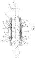
- a centralizer 12 which comprises a centralizer body 18 which is mounted on a casing 14.
- the centralizer 12 is mounted on the casing before the casing is lowered into the well bore 15, for example by clamping, bolting, welding or any other suitable ways of attaching the centralizer body 18, and thereby the centralizer 12, to the casing 14.
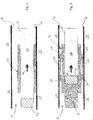
- the centralizer is in an inactive position as shown in Figure 2 .
- the centralizer can be actuated and then assumes an active position as shown in Figure 3 were the centralizer 12 has centralized the casing 14 in the well bore 15.
- the centralizer 12 comprises at least one, but preferably three or more centralizing elements 20 with a first end portion 21 and a second end portion 22, and an actuator 36 comprising an actuator device 37.
- the centralizing elements 20 are preferably spaced equally around the centralizer body 18 in a circumferential direction.
- the actuator actuates a radial or partially radial movement of the centralizing elements 20 as will be explained below.
- a movement of the centralizing elements 20 in a partially radial direction means that the movement of the centralizing element 20 has a radial component as well as an axial component relative to the longitudinal axis A of the casing 14.
- the centralizer further comprises a first link element 24 with a first end portion 25 and a second end portion 26 and a second link element 28 with a first end portion 29 and a second end portion 30.
- the first end portions 21 of the centralizing elements 20 are rotatably connected to respective first end portions 25 of the first link elements 24, and the second end portions 22 of the centralizing elements 20 are rotatably connected to respective second end portions 29 of the second link elements 28.
- the second end portion 25 of the first link element 24 is rotatably connected to the centralizer body 18 or to the actuator device 37.
- the second end portion 30 of the second link element 28 is rotatably connected the centralizer body 18 or to the actuator device 37. Either one or both of the second end portion 25 of the first link element 24 and the second end portion 30 of the second link element 28 is/are connected to the actuator device 37.
- the actuator 36 actuates the actuator device 37 which causes the axial distance between the second end portion 25 of the first link element 24 and the second end portion 30 of the second link element 28 to be reduced.
- the actuating device 37 may for example be formed as a piston/cylinder arrangement were the second end portions 25, 30 of the first link element 24 and the second link element 28 are connected respectively to the piston and the cylinder.
- the centralizing element 20 will be forced out and will engage with the wall 16 of the well bore.
- the actuating device 37 may also be in the form of a rotatable shaft with left and right hand screw threads which are in engagement with the second end portions 25, 30 of the first link element 24 and the second link element 28 respectively in a similar way to a rack and pinion gear.
- the centralizing element 20 is moved in a radial direction relative to the axis A and engages with the wall 16 of the well bore 15, whereby the casing is centralized.
- Each centralizing element 20 may be formed with a first wedge surface which is arranged with an acute angle relative to the longitudinal axis A, and the centralizer body 18 may be formed with a corresponding second wedge surface.
- the centralizing elements 20 When the centralizing elements 20 are moved in the axial direction by the actuator device 17, the centralizing elements will simultaneously be moved in a radial direction due to the wedging effect until they engage with the wall 16 of the well bore 15.
- a separate wedge element could be arranged between the centralizing element 20 and the surface of the centralizer body which is inclined relative to the longitudinal axis A.
- the centralizer system 10 further comprises a receiving unit 40.
- the receiving unit 40 is signally connected to the actuator 36 such that the receiving unit is capable of sending a signal to the actuator 36 which will cause the actuator device 37 to actuate the centralizing elements 20 so that the casing 14 is centralized in the well bore 15.
- the actuator device 40 may be connected to actuator 36 by means of a signal cable or by wireless communication such as blue tooth.
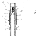
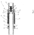
- FIG. 4-5 a second embodiment of the centralizer is shown wherein the centralizing element 20 is made of a flexible material such as spring steel.
- the first end portion 21 and the second end portion 22 of the centralizing element 20 are preferably rotatably connected to the actuator device 37.
- the actuator device 37 may be a piston/cylinder arrangement or a rotatable shaft working in a similar way to a rack and pinion gear as explained above.
- the length of the actuator device 37 can thereby be reduced which forces the flexible centralizing element 20 to bend outwards and engage with the wall 16 of the well bore 15.
- the casing 14 on which the centralizer 12 is attached is centralized in the well bore 15.
- the rest of the second embodiment of the invention, such as the receiving unit 40, is the same as the first embodiment of the invention shown in Figures 1-3 and the description of the common features are not repeated here.
- the centralizer system shown in figures 6-8 illustrates the centralizer system 10 where a centralizer 12 of the same type as the centralizers described above, is mounted on the casing 14.
- a transport element 43 is provided with a signal generator 42 which is capable of generating and transmitting a wireless signal in the form of a pressure wave, preferably a sound wave.
- the signal generator 42 may be turned on before the signal generator is moved down the well such that the wireless signal is transmitted constantly or intermittently as the transport element 43 moves down the well towards the casing 14.
- the casing is provided with one or more stop elements 13, for example one or more casing shoes, which a transport element 43 hits when the transport element arrives at the casing.
- the signal generator may be turned on by a partly or completely mechanical device (not shown in the figures).
- One or more of the stop elements 13 or, more preferably, the transport element 43 may be provided with a mechanical element such as a spring-loaded lever, a button-like element, a switch or another type of mechanical device that is suitable for turning on the signal generator.
- the signal generator 42 may be turned on directly or the movement of the lever, the button-like element or the switch may generate a signal that in turn activates the signal generator.
- the receiving unit 40 subsequently detects the wireless signal transmitted by the signal generator 42, the actuator 36 is activated and the centralizing of the casing 14 is performed.
- the receiving unit 40 further comprises a control unit (not shown on the figures) which transmits a signal to the actuator 36 for actuation of the actuator device 37 as soon as the antenna or vibration/sound sensor 41 detects the wireless signal transmitted by the signal generator 42.
- a control unit (not shown on the figures) which transmits a signal to the actuator 36 for actuation of the actuator device 37 as soon as the antenna or vibration/sound sensor 41 detects the wireless signal transmitted by the signal generator 42.
- FIG 7 a variant of the centralizer system 10 is shown.
- the casing 14 is in this embodiment not provided with stop elements 13.
- the transport element is provided with one or more sensors which are capable of measuring one or more physical parameters of the transport element's surrounding environment as the transport element is moved down the well.
- physical parameters could be the pressure and the temperature in the fluid surrounding the transport element.
- the temperature and the pressure of the well fluids in a well typically increases with the depth of the well, and for any given well, the signal generator may be set to start operating when the temperature and/or the pressure in the fluid surrounding the transport element reach a predetermined value.
- the transport element 43 may therefore be provided with a temperature sensor 44 and/or a pressure sensor 45 which is capable of measuring the temperature and pressure of the fluid surrounding the transport element 43 respectively.
- the embodiment of the transport element 43 shown in figure 7 is provided with both a temperature sensor 44 and a pressure sensor 45, but could have been provided with only a temperature sensor 44 or only a pressure sensor 45 depending on the situation. However, providing the transport element with both a temperature sensor and a pressure sensor will provide a considerably reduced risk that the signal generator 43 is not activated.
- FIG 8 a variant of the centralizer system 10 is shown where the casing 14 is provided with stop elements 13, typically a casing shoe.
- the centralizer system may therefore be provided with a mechanical device which starts the signal generator 42 when the transport element 43 hits the stop elements in the same way as explained in detail above.
- the transport element 43 is also provided with sensors 44, 45 which are capable of measuring physical parameters of the fluid surrounding the transport element, for example temperature and/or pressure, as explained above.
- the signal generator 42 of the centralizing system 10 shown in figure 8 can therefore be activated by the temperature in the fluid surrounding the transport element 43 reaching a predetermined value or the pressure in the fluid surrounding the transport element 43 reaching a predetermined value or mechanically when the transport element 43 hits the stop elements 13 in the casing 14.
- the cement slurry is usually preceded by a viper plug which separates the cement slurry 51 from the well fluids 50 in front of the cement slurry.
- a viper plug may therefore conveniently be used as a transport element for the signal generator.
- the signal generator 42 is integrated in the viper plug which will protect the signal generator from environmental hazards and prevent the signal generator from getting damaged as it is transported or pushed down the well by the cement slurry towards the casing 14 with the casing centralizer 12.
- the receiving unit 40 further comprises a control unit (not shown in the figures) which transmits a signal to the actuator 36 for actuation of the actuator device 37 as soon as the antenna 44 detects and reads (identifies).
- a control unit (not shown in the figures) which transmits a signal to the actuator 36 for actuation of the actuator device 37 as soon as the antenna 44 detects and reads (identifies).
- the centralizer system 10 works as follows.
- a centralizer 12 as shown in figures 1-3 or figures 4-5 is attached to the casing 14 which is to be centralized in the well bore 15.
- the casing 14, together with the attached centralizer 12 in an inactive position is lowered to the desired position in the well bore 15. This is shown in Figure 2 where the casing 14 with the centralizer 12 in the inactive position is not centralized in the well bore 15.
- a signal generator 42 which is moved down the well in a direction 48, preferably by the cement slurry which is later used to cement the casing to the formations in the well bore, generates and transmits a wireless signal in the form of a pressure wave, such as a sound wave.
- the centralizer system is based on the fact that the receiving unit 40 and the signal generator 42 are cooperatively configured, i.e. the signal generator generates and transmits a wireless signal, in the form of a pressure wave such as a sound wave, which the receiving unit is capable of receiving.
- the receiving unit 40 may be provided with an antenna 41 or another device or sensor capable of detecting the wireless signal transmitted by the signal generator 42.
- the signal generator 42 When the signal generator 42 is within a distance of the receiving unit 40 where the receiving unit 40 is capable of detecting the wireless signal that is transmitted by the signal generator, the receiving unit will transmit a signal to the actuator 36 so that centralizing of the casing 14 is carried out.
- the present centralizer system 10 is described above with various ways of ensuring that the signal generator 12 is activated such that the casing centralizer is activated and the casing 14 is centralized before the casing 14 is cemented in its position in the well bore.
- the signal generator 42 may be transported down the well, either integrated in a transport element 42, such as a viper plug, or as a separate entity, such that the wireless signal, for example in the form of pressure waves produced by the signal generator 42 are transmitted down the well.
- the signal generator 42 When the signal generator 42 is transported down the well, it may be operating and transmitting pressure waves from the moment it is entered the well at the top of the well, or the signal generator 42 may be activated in different ways as the signal generator approaches the casing 14, not only by using temperature sensors, pressure sensors or mechanical devices as explained above, but also other feasible devices such as an inductive coil.
Landscapes
- Engineering & Computer Science (AREA)
- Geology (AREA)
- Life Sciences & Earth Sciences (AREA)
- Mining & Mineral Resources (AREA)
- Physics & Mathematics (AREA)
- Environmental & Geological Engineering (AREA)
- Fluid Mechanics (AREA)
- General Life Sciences & Earth Sciences (AREA)
- Geochemistry & Mineralogy (AREA)
- Geophysics (AREA)
- Mechanical Engineering (AREA)
- Acoustics & Sound (AREA)
- Remote Sensing (AREA)
- Earth Drilling (AREA)
Claims (22)
- Verfahren zum Zentrieren eines Futterrohrs (14) in einem Bohrloch (15) vor dem Einzementieren des Futterrohrs im Bohrloch, wobei das Verfahren die folgenden Schritte umfasst:Montieren von wenigstens einer Zentriereinrichtung (12) am Futterrohr (14), wobei die wenigstens eine Zentriereinrichtung (12) eine Empfangseinheit (40) umfasst, die imstande ist, ein Drahtlossignal in Form einer Druckwelle zu empfangen,Positionieren des Futterrohrs (14) in dem Bohrloch (15) an einer gewünschten Position,Bereitstellen eines Drahtlossignalgenerators (42) zum Generieren und Übertragen eines Drahtlossignals in Form einer Druckwelle, welche die Empfangseinheit (40) der wenigstens einen Zentriereinrichtung (12) zu empfangen imstande ist, dadurch gekennzeichnet, dass der Signalgenerator (42) in dem Bohrloch (15) zum Futterrohr hinunterbefördert wird und der Signalgenerator (42) aktiviert wird, sodass der Signalgenerator das Drahtlossignal überträgt, wonach die Empfangseinheit (40) beim Empfang des Drahtlossignals die wenigstens eine Zentriereinrichtung (12) aktiviert und die wenigstens eine Zentriereinrichtung (12) das Futterrohr (14) in dem Bohrloch (15) zentriert.
- Verfahren nach Anspruch 1,
wobei ein Beförderungselement (43) in dem Bohrloch hinunterbefördert wird, wobei das Beförderungselement (43) den Signalgenerator (12) umfasst. - Verfahren nach einem der Ansprüche 1 bis 2,
wobei der Signalgenerator (42) ausgelöst wird, um die Übertragung des Drahtlossignals zu starten, wenn sich der Signalgenerator (42) dem Futterrohr (14) nähert oder beim Futterrohr (14) eintrifft. - Verfahren nach einem der Ansprüche 1 bis 3,
wobei der Signalgenerator (42) ausgelöst wird, um die Übertragung des Drahtlossignals zu starten, wenn der Druck in den Bohrlochflüssigkeiten, die das wenigstens eine Beförderungselement (43) umgeben, einen vorbestimmten Wert übersteigt. - Verfahren nach einem der Ansprüche 1 bis 3,
wobei der Signalgenerator (42) ausgelöst wird, um die Übertragung des Drahtlossignals zu starten, wenn die Temperatur der Bohrlochflüssigkeiten, die das wenigstens eine Beförderungselement (43) umgeben, einen vorbestimmten Wert übersteigt. - Verfahren nach einem der Ansprüche 1 bis 3,
wobei der Signalgenerator (42) mechanisch ausgelöst wird, um die Übertragung des Drahtlossignals zu starten, wenn der Signalgenerator (43) beim Futterrohr (14) eintrifft. - Verfahren nach einem der Ansprüche 1 bis 2,
wobei der Signalgenerator (42) in dem Beförderungselement (43) das Drahtlossignal kontinuierlich oder intermittierend überträgt, während er durch das Bohrloch (15) befördert wird. - Verfahren nach einem der Ansprüche 1 bis 7,
wobei eine Vielzahl von Zentriereinrichtungen (12) in dem Bohrloch (15) vorgesehen ist und die Zentriereinrichtungen (12) signalmäßig derart verbunden sind, dass, wenn die Empfangseinheit (40) einer ersten Zentriereinrichtung (12) das Drahtlossignal empfängt, das Signal zu wenigstens einer der übrigen Zentriereinrichtungen (12) weitergeleitet wird, welche die Zentrierung des Futterrohrs (14) initiiert, an dem sie montiert ist. - Verfahren nach einem der Ansprüche 1 bis 8,
wobei die Druckwelle ein Schallsignal ist. - Verfahren nach einem der Ansprüche 1 bis 9,
wobei das Beförderungselement (43) mittels Zementschlamm in dem Bohrloch hinuntergepumpt wird. - Verfahren nach einem der Ansprüche 1 bis 10,
wobei das Beförderungselement (43) ein Viper Plug ist. - Zentriersystem (10) zum Zentrieren eines Futterrohrs (14) in einem Bohrloch (15) vor dem Einzementieren des Futterrohrs (14) in dem Bohrloch (15), wobei das Zentriersystem (10) Folgendes umfasst:wenigstens eine Zentriereinrichtung (12), die dafür eingerichtet ist, an dem Futterrohr (14) montiert zu werden, wobei die wenigstens eine Zentriereinrichtung (12) eine Empfangseinheit (40) umfasst, die imstande ist, ein Drahtlossignal in Form von Druckwellen zu empfangen,wobei die wenigstens eine Zentriereinrichtung (12) derart ausgebildet ist, dass die Zentriereinrichtung (12) aktiviert wird, um das Futterrohr (14) zu zentrieren, wenn die Empfangseinheit (40) das Drahtlossignal empfängt, das durch einen Signalgenerator (42) übertragen wird,dadurch gekennzeichnet, dass das Zentriersystem (10) einen Drahtlossignalgenerator (42) umfasst, der dafür eingerichtet ist, in dem Bohrloch (15) hinunterbefördert zu werden und das Drahtlossignal in Form einer Druckwelle, das die Empfangseinheit (40) der wenigstens einen Zentriereinrichtung (12) zu empfangen imstande ist, zu generieren und zu übertragen.
- Zentriersystem nach Anspruch 12,
dadurch gekennzeichnet, dass das Zentriersystem (10) ein Beförderungselement (43) umfasst, wobei das Beförderungselement (43) den Signalgenerator (42) umfasst. - Zentriersystem nach einem der Ansprüche 12 bis 13,
dadurch gekennzeichnet, dass das Zentriersystem (10) einen Drucksensor (45) umfasst, der in dem Signalgenerator (42) oder dem Beförderungselement (43) enthalten ist, wobei der Signalgenerator (42) dafür eingerichtet ist, aktiviert zu werden, wenn der Druck in dem Bohrloch (15) einen vorbestimmten Wert übersteigt. - Zentriersystem nach einem der Ansprüche 12 bis 14,
dadurch gekennzeichnet, dass das Zentriersystem (10) einen Temperatursensor (44) umfasst, der in dem Signalgenerator (42) oder dem Beförderungselement (43) enthalten ist, wobei der Signalgenerator (42) dafür eingerichtet ist, aktiviert zu werden, wenn die Temperatur in dem Bohrloch (15) einen vorbestimmten Wert übersteigt. - Zentriersystem nach einem der Ansprüche 12 bis 14,
dadurch gekennzeichnet, dass die wenigstens eine Zentriereinrichtung (12) und/oder der Signalgenerator (42) und/oder das Beförderungselement (43) mit einer mechanischen Vorrichtung versehen ist, die den Signalgenerator (42) aktiviert, wenn der Signalgenerator beim Futterrohr (14) eintrifft. - Zentriersystem nach einem der Ansprüche 12 bis 15,
dadurch gekennzeichnet, dass das Zentriersystem (10) eine Vielzahl von Zentriereinrichtungen (12) umfasst und dass die Zentriereinrichtungen (12) signalmäßig derart verbunden sind, dass, wenn die Empfangseinheit (40) einer ersten Zentriereinrichtung (12) das Drahtlossignal empfängt, das Signal zu wenigstens einer der übrigen Zentriereinrichtungen (12) weitergeleitet wird, welche die Zentrierung des Futterrohrs (14) initiiert, an dem sie montiert ist. - Zentriersystem nach einem der Ansprüche 12 bis 17,
dadurch gekennzeichnet, dass die Druckwelle ein Schallsignal ist. - Zentriersystem nach einem der Ansprüche 12 bis 18,
dadurch gekennzeichnet, dass das Beförderungselement (43) ein Viper Plug ist. - Verwendung eines Verfahrens nach einem der Ansprüche 1 bis 11 zum Initiieren des Zentrierens eines Futterrohrs (14) in einem Bohrloch (15) vor dem Einzementieren des Futterrohrs (14), wobei das Drahtlossignal in Form einer Druckwelle vorliegt und das Drahtlossignal durch den Signalgenerator (42) übertragen wird, der das Bohrloch (15) hinunterbefördert wird.
- Verwendung eines Systems nach einem der Ansprüche 12 bis 19 zum Initiieren des Zentrierens eines Futterrohrs (14) in einem Bohrloch (15) vor dem Einzementieren des Futterrohrs (14), wobei das Drahtlossignal in Form einer Druckwelle vorliegt und das Drahtlossignal durch den Signalgenerator (42) übertragen wird, der das Bohrloch (15) hinunterbefördert wird.
- Verwendung eines Drahtlossignals nach Anspruch 20 oder 21, wobei die Druckwelle eine Schallwelle ist.
Applications Claiming Priority (2)
| Application Number | Priority Date | Filing Date | Title |
|---|---|---|---|
| NO20141201A NO341735B1 (no) | 2014-10-08 | 2014-10-08 | En fremgangsmåte og et system for sentralisering av et fôringsrør i en brønn |
| PCT/EP2015/073167 WO2016055530A1 (en) | 2014-10-08 | 2015-10-07 | A method and a centralizer system for centralizing a casing in a well bore |
Publications (2)
| Publication Number | Publication Date |
|---|---|
| EP3204591A1 EP3204591A1 (de) | 2017-08-16 |
| EP3204591B1 true EP3204591B1 (de) | 2019-01-23 |
Family
ID=54252316
Family Applications (1)
| Application Number | Title | Priority Date | Filing Date |
|---|---|---|---|
| EP15775225.4A Active EP3204591B1 (de) | 2014-10-08 | 2015-10-07 | Verfahren und zentriersystem zur zentralisierung eines bohrrohres in einem bohrloch |
Country Status (4)
| Country | Link |
|---|---|
| US (1) | US20170241215A1 (de) |
| EP (1) | EP3204591B1 (de) |
| NO (1) | NO341735B1 (de) |
| WO (1) | WO2016055530A1 (de) |
Families Citing this family (11)
| Publication number | Priority date | Publication date | Assignee | Title |
|---|---|---|---|---|
| AR114714A1 (es) | 2018-03-26 | 2020-10-07 | Baker Hughes A Ge Co Llc | Sistema para mitigación de gases en bombas de profundidad |
| US11268356B2 (en) | 2018-06-29 | 2022-03-08 | Halliburton Energy Services, Inc. | Casing conveyed, externally mounted perforation concept |
| WO2020006268A1 (en) * | 2018-06-29 | 2020-01-02 | Halliburton Energy Services, Inc. | Casing conveyed, externally mounted perforation concept |
| US10995581B2 (en) | 2018-07-26 | 2021-05-04 | Baker Hughes Oilfield Operations Llc | Self-cleaning packer system |
| CN109681195A (zh) * | 2019-02-25 | 2019-04-26 | 中国矿业大学(北京) | 一种井下钻孔内沿程温度红外测试装置及方法 |
| EP3969725A4 (de) * | 2019-05-13 | 2023-08-16 | Baker Hughes Oilfield Operations LLC | Bohrlochpumpsystem mit geschwindigkeitsröhre und mehrphasenumleiter |
| US11643916B2 (en) | 2019-05-30 | 2023-05-09 | Baker Hughes Oilfield Operations Llc | Downhole pumping system with cyclonic solids separator |
| CN112832704B (zh) * | 2021-01-29 | 2024-06-21 | 成都维锐泰达能源技术有限公司 | 用于泵送智能开启装置的减震扶正装置、智能开启装置及多级压裂智能控制系统 |
| EP4555189A4 (de) | 2022-07-12 | 2025-12-10 | Baker Hughes Oilfield Operations Llc | Verbesserte externe rückführung zur gasschleusenentlastung |
| US12152475B2 (en) | 2022-10-18 | 2024-11-26 | Baker Hughes Oilfield Operations Llc | Intake fluid density control system |
| US12503933B2 (en) | 2023-10-11 | 2025-12-23 | Baker Hughes Oilfield Operations Llc | Electric submersible pump gas evacuation system |
Family Cites Families (8)
| Publication number | Priority date | Publication date | Assignee | Title |
|---|---|---|---|---|
| GB2296925B (en) * | 1993-10-07 | 1997-04-23 | Conoco Inc | Casing conveyed system for completing a wellbore |
| US7252152B2 (en) * | 2003-06-18 | 2007-08-07 | Weatherford/Lamb, Inc. | Methods and apparatus for actuating a downhole tool |
| US7387165B2 (en) * | 2004-12-14 | 2008-06-17 | Schlumberger Technology Corporation | System for completing multiple well intervals |
| US7775272B2 (en) * | 2007-03-14 | 2010-08-17 | Schlumberger Technology Corporation | Passive centralizer |
| EP2604785A1 (de) * | 2008-09-29 | 2013-06-19 | Frank's International, Inc. | Bohrlochvorrichtungsaktuator und Verfahren dafür |
| US9482072B2 (en) * | 2013-07-23 | 2016-11-01 | Halliburton Energy Services, Inc. | Selective electrical activation of downhole tools |
| CA2919190A1 (en) * | 2013-07-24 | 2015-01-29 | Bp Corporation North America Inc. | Centralizers for centralizing well casings |
| US8851193B1 (en) * | 2014-04-09 | 2014-10-07 | Cary A. Valerio | Self-centering downhole tool |
-
2014
- 2014-10-08 NO NO20141201A patent/NO341735B1/no unknown
-
2015
- 2015-10-07 WO PCT/EP2015/073167 patent/WO2016055530A1/en not_active Ceased
- 2015-10-07 US US15/517,168 patent/US20170241215A1/en not_active Abandoned
- 2015-10-07 EP EP15775225.4A patent/EP3204591B1/de active Active
Non-Patent Citations (1)
| Title |
|---|
| None * |
Also Published As
| Publication number | Publication date |
|---|---|
| EP3204591A1 (de) | 2017-08-16 |
| WO2016055530A1 (en) | 2016-04-14 |
| NO341735B1 (no) | 2018-01-15 |
| NO20141201A1 (no) | 2016-04-11 |
| US20170241215A1 (en) | 2017-08-24 |
Similar Documents
| Publication | Publication Date | Title |
|---|---|---|
| US20170241215A1 (en) | A method and a centralizer system for centralizing a casing in a well bore | |
| EP3186475B1 (de) | Drahtloses bohrlochübertragungssystem | |
| NO336909B1 (no) | Fremgangsmåter og apparat for aktivering av et nedihulls-verktøy | |
| US8950480B1 (en) | Downhole tool delivery system with self activating perforation gun with attached perforation hole blocking assembly | |
| US8272439B2 (en) | Downhole tool delivery system with self activating perforation gun | |
| US20150330200A1 (en) | Apparatus and Method for Operating a Device in a Wellbore Using Signals Generated in Response to Strain on a Downhole Member | |
| CA2870053A1 (en) | Location of downhole lines | |
| US20200378221A1 (en) | Slickline Selective Perforation System | |
| CN112055773A (zh) | 通过智能扶正器支撑井筒内的管柱 | |
| GB2581661A (en) | Inner and outer downhole structures having downlink activation | |
| US20160222764A1 (en) | Ball drop tool and methods of use | |
| EP3611331A1 (de) | Rotationslenkvorrichtung basierend auf radialer antriebskraft | |
| NO348234B1 (en) | Electronically-activated liner hangers and methods of setting same in wellbore | |
| EP2354445B1 (de) | Akustisches Telemetriesystem zur Verwendung in einer Bohrlochsohlenbaugruppe | |
| US8887817B2 (en) | Intermediate disconnection tool to be placed in a shuttle lowered into a well for exploiting a fluid, and related shuttle and method | |
| EP2366865B1 (de) | Versetztes Verbindungsstück für Bohrlochwerkzeuge | |
| WO2016018268A1 (en) | Downhole tool anchoring device | |
| US11459841B2 (en) | Apparatus for performing multiple downhole operations in a production tubing | |
| EP3042037B1 (de) | Bohrloch-kommunikationsmodul | |
| NO346960B1 (no) | System og metode for retningsstyrt boring og samtidig utfôring av et borehull | |
| RU2016143498A (ru) | Способ формирования детонационной цепи в скважинных перфораторах и варианты устройства для его осуществления |
Legal Events
| Date | Code | Title | Description |
|---|---|---|---|
| STAA | Information on the status of an ep patent application or granted ep patent |
Free format text: STATUS: THE INTERNATIONAL PUBLICATION HAS BEEN MADE |
|
| PUAI | Public reference made under article 153(3) epc to a published international application that has entered the european phase |
Free format text: ORIGINAL CODE: 0009012 |
|
| STAA | Information on the status of an ep patent application or granted ep patent |
Free format text: STATUS: REQUEST FOR EXAMINATION WAS MADE |
|
| 17P | Request for examination filed |
Effective date: 20170505 |
|
| AK | Designated contracting states |
Kind code of ref document: A1 Designated state(s): AL AT BE BG CH CY CZ DE DK EE ES FI FR GB GR HR HU IE IS IT LI LT LU LV MC MK MT NL NO PL PT RO RS SE SI SK SM TR |
|
| AX | Request for extension of the european patent |
Extension state: BA ME |
|
| DAV | Request for validation of the european patent (deleted) | ||
| DAX | Request for extension of the european patent (deleted) | ||
| GRAP | Despatch of communication of intention to grant a patent |
Free format text: ORIGINAL CODE: EPIDOSNIGR1 |
|
| STAA | Information on the status of an ep patent application or granted ep patent |
Free format text: STATUS: GRANT OF PATENT IS INTENDED |
|
| INTG | Intention to grant announced |
Effective date: 20180316 |
|
| GRAJ | Information related to disapproval of communication of intention to grant by the applicant or resumption of examination proceedings by the epo deleted |
Free format text: ORIGINAL CODE: EPIDOSDIGR1 |
|
| STAA | Information on the status of an ep patent application or granted ep patent |
Free format text: STATUS: REQUEST FOR EXAMINATION WAS MADE |
|
| INTC | Intention to grant announced (deleted) | ||
| GRAP | Despatch of communication of intention to grant a patent |
Free format text: ORIGINAL CODE: EPIDOSNIGR1 |
|
| STAA | Information on the status of an ep patent application or granted ep patent |
Free format text: STATUS: GRANT OF PATENT IS INTENDED |
|
| INTG | Intention to grant announced |
Effective date: 20180907 |
|
| GRAS | Grant fee paid |
Free format text: ORIGINAL CODE: EPIDOSNIGR3 |
|
| GRAA | (expected) grant |
Free format text: ORIGINAL CODE: 0009210 |
|
| STAA | Information on the status of an ep patent application or granted ep patent |
Free format text: STATUS: THE PATENT HAS BEEN GRANTED |
|
| AK | Designated contracting states |
Kind code of ref document: B1 Designated state(s): AL AT BE BG CH CY CZ DE DK EE ES FI FR GB GR HR HU IE IS IT LI LT LU LV MC MK MT NL NO PL PT RO RS SE SI SK SM TR |
|
| REG | Reference to a national code |
Ref country code: GB Ref legal event code: FG4D |
|
| REG | Reference to a national code |
Ref country code: CH Ref legal event code: EP |
|
| REG | Reference to a national code |
Ref country code: AT Ref legal event code: REF Ref document number: 1091586 Country of ref document: AT Kind code of ref document: T Effective date: 20190215 |
|
| REG | Reference to a national code |
Ref country code: IE Ref legal event code: FG4D |
|
| REG | Reference to a national code |
Ref country code: DE Ref legal event code: R096 Ref document number: 602015023723 Country of ref document: DE |
|
| REG | Reference to a national code |
Ref country code: NL Ref legal event code: MP Effective date: 20190123 |
|
| PG25 | Lapsed in a contracting state [announced via postgrant information from national office to epo] |
Ref country code: NL Free format text: LAPSE BECAUSE OF FAILURE TO SUBMIT A TRANSLATION OF THE DESCRIPTION OR TO PAY THE FEE WITHIN THE PRESCRIBED TIME-LIMIT Effective date: 20190123 |
|
| PG25 | Lapsed in a contracting state [announced via postgrant information from national office to epo] |
Ref country code: ES Free format text: LAPSE BECAUSE OF FAILURE TO SUBMIT A TRANSLATION OF THE DESCRIPTION OR TO PAY THE FEE WITHIN THE PRESCRIBED TIME-LIMIT Effective date: 20190123 Ref country code: PL Free format text: LAPSE BECAUSE OF FAILURE TO SUBMIT A TRANSLATION OF THE DESCRIPTION OR TO PAY THE FEE WITHIN THE PRESCRIBED TIME-LIMIT Effective date: 20190123 Ref country code: PT Free format text: LAPSE BECAUSE OF FAILURE TO SUBMIT A TRANSLATION OF THE DESCRIPTION OR TO PAY THE FEE WITHIN THE PRESCRIBED TIME-LIMIT Effective date: 20190523 Ref country code: NO Free format text: LAPSE BECAUSE OF FAILURE TO SUBMIT A TRANSLATION OF THE DESCRIPTION OR TO PAY THE FEE WITHIN THE PRESCRIBED TIME-LIMIT Effective date: 20190423 Ref country code: SE Free format text: LAPSE BECAUSE OF FAILURE TO SUBMIT A TRANSLATION OF THE DESCRIPTION OR TO PAY THE FEE WITHIN THE PRESCRIBED TIME-LIMIT Effective date: 20190123 Ref country code: FI Free format text: LAPSE BECAUSE OF FAILURE TO SUBMIT A TRANSLATION OF THE DESCRIPTION OR TO PAY THE FEE WITHIN THE PRESCRIBED TIME-LIMIT Effective date: 20190123 Ref country code: LT Free format text: LAPSE BECAUSE OF FAILURE TO SUBMIT A TRANSLATION OF THE DESCRIPTION OR TO PAY THE FEE WITHIN THE PRESCRIBED TIME-LIMIT Effective date: 20190123 |
|
| REG | Reference to a national code |
Ref country code: AT Ref legal event code: MK05 Ref document number: 1091586 Country of ref document: AT Kind code of ref document: T Effective date: 20190123 |
|
| PG25 | Lapsed in a contracting state [announced via postgrant information from national office to epo] |
Ref country code: IS Free format text: LAPSE BECAUSE OF FAILURE TO SUBMIT A TRANSLATION OF THE DESCRIPTION OR TO PAY THE FEE WITHIN THE PRESCRIBED TIME-LIMIT Effective date: 20190523 Ref country code: BG Free format text: LAPSE BECAUSE OF FAILURE TO SUBMIT A TRANSLATION OF THE DESCRIPTION OR TO PAY THE FEE WITHIN THE PRESCRIBED TIME-LIMIT Effective date: 20190423 Ref country code: RS Free format text: LAPSE BECAUSE OF FAILURE TO SUBMIT A TRANSLATION OF THE DESCRIPTION OR TO PAY THE FEE WITHIN THE PRESCRIBED TIME-LIMIT Effective date: 20190123 Ref country code: HR Free format text: LAPSE BECAUSE OF FAILURE TO SUBMIT A TRANSLATION OF THE DESCRIPTION OR TO PAY THE FEE WITHIN THE PRESCRIBED TIME-LIMIT Effective date: 20190123 Ref country code: GR Free format text: LAPSE BECAUSE OF FAILURE TO SUBMIT A TRANSLATION OF THE DESCRIPTION OR TO PAY THE FEE WITHIN THE PRESCRIBED TIME-LIMIT Effective date: 20190424 Ref country code: LV Free format text: LAPSE BECAUSE OF FAILURE TO SUBMIT A TRANSLATION OF THE DESCRIPTION OR TO PAY THE FEE WITHIN THE PRESCRIBED TIME-LIMIT Effective date: 20190123 |
|
| REG | Reference to a national code |
Ref country code: DE Ref legal event code: R097 Ref document number: 602015023723 Country of ref document: DE |
|
| PG25 | Lapsed in a contracting state [announced via postgrant information from national office to epo] |
Ref country code: CZ Free format text: LAPSE BECAUSE OF FAILURE TO SUBMIT A TRANSLATION OF THE DESCRIPTION OR TO PAY THE FEE WITHIN THE PRESCRIBED TIME-LIMIT Effective date: 20190123 Ref country code: SK Free format text: LAPSE BECAUSE OF FAILURE TO SUBMIT A TRANSLATION OF THE DESCRIPTION OR TO PAY THE FEE WITHIN THE PRESCRIBED TIME-LIMIT Effective date: 20190123 Ref country code: RO Free format text: LAPSE BECAUSE OF FAILURE TO SUBMIT A TRANSLATION OF THE DESCRIPTION OR TO PAY THE FEE WITHIN THE PRESCRIBED TIME-LIMIT Effective date: 20190123 Ref country code: AL Free format text: LAPSE BECAUSE OF FAILURE TO SUBMIT A TRANSLATION OF THE DESCRIPTION OR TO PAY THE FEE WITHIN THE PRESCRIBED TIME-LIMIT Effective date: 20190123 Ref country code: IT Free format text: LAPSE BECAUSE OF FAILURE TO SUBMIT A TRANSLATION OF THE DESCRIPTION OR TO PAY THE FEE WITHIN THE PRESCRIBED TIME-LIMIT Effective date: 20190123 Ref country code: DK Free format text: LAPSE BECAUSE OF FAILURE TO SUBMIT A TRANSLATION OF THE DESCRIPTION OR TO PAY THE FEE WITHIN THE PRESCRIBED TIME-LIMIT Effective date: 20190123 Ref country code: EE Free format text: LAPSE BECAUSE OF FAILURE TO SUBMIT A TRANSLATION OF THE DESCRIPTION OR TO PAY THE FEE WITHIN THE PRESCRIBED TIME-LIMIT Effective date: 20190123 |
|
| PG25 | Lapsed in a contracting state [announced via postgrant information from national office to epo] |
Ref country code: SM Free format text: LAPSE BECAUSE OF FAILURE TO SUBMIT A TRANSLATION OF THE DESCRIPTION OR TO PAY THE FEE WITHIN THE PRESCRIBED TIME-LIMIT Effective date: 20190123 |
|
| PLBE | No opposition filed within time limit |
Free format text: ORIGINAL CODE: 0009261 |
|
| STAA | Information on the status of an ep patent application or granted ep patent |
Free format text: STATUS: NO OPPOSITION FILED WITHIN TIME LIMIT |
|
| PG25 | Lapsed in a contracting state [announced via postgrant information from national office to epo] |
Ref country code: AT Free format text: LAPSE BECAUSE OF FAILURE TO SUBMIT A TRANSLATION OF THE DESCRIPTION OR TO PAY THE FEE WITHIN THE PRESCRIBED TIME-LIMIT Effective date: 20190123 |
|
| 26N | No opposition filed |
Effective date: 20191024 |
|
| PG25 | Lapsed in a contracting state [announced via postgrant information from national office to epo] |
Ref country code: SI Free format text: LAPSE BECAUSE OF FAILURE TO SUBMIT A TRANSLATION OF THE DESCRIPTION OR TO PAY THE FEE WITHIN THE PRESCRIBED TIME-LIMIT Effective date: 20190123 |
|
| PG25 | Lapsed in a contracting state [announced via postgrant information from national office to epo] |
Ref country code: TR Free format text: LAPSE BECAUSE OF FAILURE TO SUBMIT A TRANSLATION OF THE DESCRIPTION OR TO PAY THE FEE WITHIN THE PRESCRIBED TIME-LIMIT Effective date: 20190123 |
|
| REG | Reference to a national code |
Ref country code: DE Ref legal event code: R119 Ref document number: 602015023723 Country of ref document: DE |
|
| PG25 | Lapsed in a contracting state [announced via postgrant information from national office to epo] |
Ref country code: MC Free format text: LAPSE BECAUSE OF FAILURE TO SUBMIT A TRANSLATION OF THE DESCRIPTION OR TO PAY THE FEE WITHIN THE PRESCRIBED TIME-LIMIT Effective date: 20190123 |
|
| REG | Reference to a national code |
Ref country code: CH Ref legal event code: PL |
|
| PG25 | Lapsed in a contracting state [announced via postgrant information from national office to epo] |
Ref country code: DE Free format text: LAPSE BECAUSE OF NON-PAYMENT OF DUE FEES Effective date: 20200501 Ref country code: LU Free format text: LAPSE BECAUSE OF NON-PAYMENT OF DUE FEES Effective date: 20191007 Ref country code: CH Free format text: LAPSE BECAUSE OF NON-PAYMENT OF DUE FEES Effective date: 20191031 Ref country code: LI Free format text: LAPSE BECAUSE OF NON-PAYMENT OF DUE FEES Effective date: 20191031 |
|
| REG | Reference to a national code |
Ref country code: BE Ref legal event code: MM Effective date: 20191031 |
|
| PG25 | Lapsed in a contracting state [announced via postgrant information from national office to epo] |
Ref country code: BE Free format text: LAPSE BECAUSE OF NON-PAYMENT OF DUE FEES Effective date: 20191031 |
|
| PG25 | Lapsed in a contracting state [announced via postgrant information from national office to epo] |
Ref country code: IE Free format text: LAPSE BECAUSE OF NON-PAYMENT OF DUE FEES Effective date: 20191007 Ref country code: FR Free format text: LAPSE BECAUSE OF NON-PAYMENT OF DUE FEES Effective date: 20191031 |
|
| PG25 | Lapsed in a contracting state [announced via postgrant information from national office to epo] |
Ref country code: CY Free format text: LAPSE BECAUSE OF FAILURE TO SUBMIT A TRANSLATION OF THE DESCRIPTION OR TO PAY THE FEE WITHIN THE PRESCRIBED TIME-LIMIT Effective date: 20190123 |
|
| PG25 | Lapsed in a contracting state [announced via postgrant information from national office to epo] |
Ref country code: HU Free format text: LAPSE BECAUSE OF FAILURE TO SUBMIT A TRANSLATION OF THE DESCRIPTION OR TO PAY THE FEE WITHIN THE PRESCRIBED TIME-LIMIT; INVALID AB INITIO Effective date: 20151007 Ref country code: MT Free format text: LAPSE BECAUSE OF FAILURE TO SUBMIT A TRANSLATION OF THE DESCRIPTION OR TO PAY THE FEE WITHIN THE PRESCRIBED TIME-LIMIT Effective date: 20190123 |
|
| PG25 | Lapsed in a contracting state [announced via postgrant information from national office to epo] |
Ref country code: MK Free format text: LAPSE BECAUSE OF FAILURE TO SUBMIT A TRANSLATION OF THE DESCRIPTION OR TO PAY THE FEE WITHIN THE PRESCRIBED TIME-LIMIT Effective date: 20190123 |
|
| PGFP | Annual fee paid to national office [announced via postgrant information from national office to epo] |
Ref country code: GB Payment date: 20251013 Year of fee payment: 11 |