EP3204582B1 - Hinge device for doors, shutters or the like - Google Patents
Hinge device for doors, shutters or the like Download PDFInfo
- Publication number
- EP3204582B1 EP3204582B1 EP15794639.3A EP15794639A EP3204582B1 EP 3204582 B1 EP3204582 B1 EP 3204582B1 EP 15794639 A EP15794639 A EP 15794639A EP 3204582 B1 EP3204582 B1 EP 3204582B1
- Authority
- EP
- European Patent Office
- Prior art keywords
- compartment
- duct
- closing
- working chamber
- end cap
- Prior art date
- Legal status (The legal status is an assumption and is not a legal conclusion. Google has not performed a legal analysis and makes no representation as to the accuracy of the status listed.)
- Active
Links
- 239000012530 fluid Substances 0.000 claims description 54
- 238000004891 communication Methods 0.000 claims description 20
- 230000002093 peripheral effect Effects 0.000 claims description 8
- 230000008878 coupling Effects 0.000 claims description 3
- 238000010168 coupling process Methods 0.000 claims description 3
- 238000005859 coupling reaction Methods 0.000 claims description 3
- 230000000903 blocking effect Effects 0.000 description 2
- 239000000470 constituent Substances 0.000 description 2
- 238000004519 manufacturing process Methods 0.000 description 2
- 230000001668 ameliorated effect Effects 0.000 description 1
- 230000000712 assembly Effects 0.000 description 1
- 238000000429 assembly Methods 0.000 description 1
- 238000013016 damping Methods 0.000 description 1
- 230000001419 dependent effect Effects 0.000 description 1
- 238000001125 extrusion Methods 0.000 description 1
- 238000012423 maintenance Methods 0.000 description 1
- 239000000463 material Substances 0.000 description 1
- 238000012986 modification Methods 0.000 description 1
- 230000004048 modification Effects 0.000 description 1
- 238000007789 sealing Methods 0.000 description 1
- 230000000007 visual effect Effects 0.000 description 1
Images


Classifications
-
- E—FIXED CONSTRUCTIONS
- E05—LOCKS; KEYS; WINDOW OR DOOR FITTINGS; SAFES
- E05F—DEVICES FOR MOVING WINGS INTO OPEN OR CLOSED POSITION; CHECKS FOR WINGS; WING FITTINGS NOT OTHERWISE PROVIDED FOR, CONCERNED WITH THE FUNCTIONING OF THE WING
- E05F3/00—Closers or openers with braking devices, e.g. checks; Construction of pneumatic or liquid braking devices
- E05F3/04—Closers or openers with braking devices, e.g. checks; Construction of pneumatic or liquid braking devices with liquid piston brakes
-
- E—FIXED CONSTRUCTIONS
- E05—LOCKS; KEYS; WINDOW OR DOOR FITTINGS; SAFES
- E05D—HINGES OR SUSPENSION DEVICES FOR DOORS, WINDOWS OR WINGS
- E05D3/00—Hinges with pins
- E05D3/02—Hinges with pins with one pin
-
- E—FIXED CONSTRUCTIONS
- E05—LOCKS; KEYS; WINDOW OR DOOR FITTINGS; SAFES
- E05F—DEVICES FOR MOVING WINGS INTO OPEN OR CLOSED POSITION; CHECKS FOR WINGS; WING FITTINGS NOT OTHERWISE PROVIDED FOR, CONCERNED WITH THE FUNCTIONING OF THE WING
- E05F3/00—Closers or openers with braking devices, e.g. checks; Construction of pneumatic or liquid braking devices
- E05F3/04—Closers or openers with braking devices, e.g. checks; Construction of pneumatic or liquid braking devices with liquid piston brakes
- E05F3/12—Special devices controlling the circulation of the liquid, e.g. valve arrangement
-
- E—FIXED CONSTRUCTIONS
- E05—LOCKS; KEYS; WINDOW OR DOOR FITTINGS; SAFES
- E05F—DEVICES FOR MOVING WINGS INTO OPEN OR CLOSED POSITION; CHECKS FOR WINGS; WING FITTINGS NOT OTHERWISE PROVIDED FOR, CONCERNED WITH THE FUNCTIONING OF THE WING
- E05F3/00—Closers or openers with braking devices, e.g. checks; Construction of pneumatic or liquid braking devices
- E05F3/20—Closers or openers with braking devices, e.g. checks; Construction of pneumatic or liquid braking devices in hinges
-
- E—FIXED CONSTRUCTIONS
- E05—LOCKS; KEYS; WINDOW OR DOOR FITTINGS; SAFES
- E05F—DEVICES FOR MOVING WINGS INTO OPEN OR CLOSED POSITION; CHECKS FOR WINGS; WING FITTINGS NOT OTHERWISE PROVIDED FOR, CONCERNED WITH THE FUNCTIONING OF THE WING
- E05F1/00—Closers or openers for wings, not otherwise provided for in this subclass
- E05F1/08—Closers or openers for wings, not otherwise provided for in this subclass spring-actuated, e.g. for horizontally sliding wings
- E05F1/10—Closers or openers for wings, not otherwise provided for in this subclass spring-actuated, e.g. for horizontally sliding wings for swinging wings, e.g. counterbalance
- E05F1/12—Mechanisms in the shape of hinges or pivots, operated by springs
- E05F1/1207—Mechanisms in the shape of hinges or pivots, operated by springs with a coil spring parallel with the pivot axis
- E05F1/1223—Mechanisms in the shape of hinges or pivots, operated by springs with a coil spring parallel with the pivot axis with a compression or traction spring
-
- E—FIXED CONSTRUCTIONS
- E05—LOCKS; KEYS; WINDOW OR DOOR FITTINGS; SAFES
- E05F—DEVICES FOR MOVING WINGS INTO OPEN OR CLOSED POSITION; CHECKS FOR WINGS; WING FITTINGS NOT OTHERWISE PROVIDED FOR, CONCERNED WITH THE FUNCTIONING OF THE WING
- E05F3/00—Closers or openers with braking devices, e.g. checks; Construction of pneumatic or liquid braking devices
- E05F3/04—Closers or openers with braking devices, e.g. checks; Construction of pneumatic or liquid braking devices with liquid piston brakes
- E05F3/10—Closers or openers with braking devices, e.g. checks; Construction of pneumatic or liquid braking devices with liquid piston brakes with a spring, other than a torsion spring, and a piston, the axes of which are the same or lie in the same direction
- E05F3/104—Closers or openers with braking devices, e.g. checks; Construction of pneumatic or liquid braking devices with liquid piston brakes with a spring, other than a torsion spring, and a piston, the axes of which are the same or lie in the same direction with cam-and-slide transmission between driving shaft and piston within the closer housing
-
- E—FIXED CONSTRUCTIONS
- E05—LOCKS; KEYS; WINDOW OR DOOR FITTINGS; SAFES
- E05Y—INDEXING SCHEME RELATING TO HINGES OR OTHER SUSPENSION DEVICES FOR DOORS, WINDOWS OR WINGS AND DEVICES FOR MOVING WINGS INTO OPEN OR CLOSED POSITION, CHECKS FOR WINGS AND WING FITTINGS NOT OTHERWISE PROVIDED FOR, CONCERNED WITH THE FUNCTIONING OF THE WING
- E05Y2201/00—Constructional elements; Accessories therefore
- E05Y2201/20—Brakes; Disengaging means, e.g. clutches; Holders, e.g. locks; Stops; Accessories therefore
- E05Y2201/21—Brakes
- E05Y2201/212—Buffers
-
- E—FIXED CONSTRUCTIONS
- E05—LOCKS; KEYS; WINDOW OR DOOR FITTINGS; SAFES
- E05Y—INDEXING SCHEME RELATING TO HINGES OR OTHER SUSPENSION DEVICES FOR DOORS, WINDOWS OR WINGS AND DEVICES FOR MOVING WINGS INTO OPEN OR CLOSED POSITION, CHECKS FOR WINGS AND WING FITTINGS NOT OTHERWISE PROVIDED FOR, CONCERNED WITH THE FUNCTIONING OF THE WING
- E05Y2201/00—Constructional elements; Accessories therefore
- E05Y2201/20—Brakes; Disengaging means, e.g. clutches; Holders, e.g. locks; Stops; Accessories therefore
- E05Y2201/262—Brakes; Disengaging means, e.g. clutches; Holders, e.g. locks; Stops; Accessories therefore characterised by type of motion
- E05Y2201/264—Brakes; Disengaging means, e.g. clutches; Holders, e.g. locks; Stops; Accessories therefore characterised by type of motion linear
-
- E—FIXED CONSTRUCTIONS
- E05—LOCKS; KEYS; WINDOW OR DOOR FITTINGS; SAFES
- E05Y—INDEXING SCHEME RELATING TO HINGES OR OTHER SUSPENSION DEVICES FOR DOORS, WINDOWS OR WINGS AND DEVICES FOR MOVING WINGS INTO OPEN OR CLOSED POSITION, CHECKS FOR WINGS AND WING FITTINGS NOT OTHERWISE PROVIDED FOR, CONCERNED WITH THE FUNCTIONING OF THE WING
- E05Y2800/00—Details, accessories and auxiliary operations not otherwise provided for
- E05Y2800/40—Protection
- E05Y2800/424—Protection against unintended use
-
- E—FIXED CONSTRUCTIONS
- E05—LOCKS; KEYS; WINDOW OR DOOR FITTINGS; SAFES
- E05Y—INDEXING SCHEME RELATING TO HINGES OR OTHER SUSPENSION DEVICES FOR DOORS, WINDOWS OR WINGS AND DEVICES FOR MOVING WINGS INTO OPEN OR CLOSED POSITION, CHECKS FOR WINGS AND WING FITTINGS NOT OTHERWISE PROVIDED FOR, CONCERNED WITH THE FUNCTIONING OF THE WING
- E05Y2900/00—Application of doors, windows, wings or fittings thereof
- E05Y2900/10—Application of doors, windows, wings or fittings thereof for buildings or parts thereof
- E05Y2900/13—Application of doors, windows, wings or fittings thereof for buildings or parts thereof characterised by the type of wing
- E05Y2900/132—Doors
-
- E—FIXED CONSTRUCTIONS
- E05—LOCKS; KEYS; WINDOW OR DOOR FITTINGS; SAFES
- E05Y—INDEXING SCHEME RELATING TO HINGES OR OTHER SUSPENSION DEVICES FOR DOORS, WINDOWS OR WINGS AND DEVICES FOR MOVING WINGS INTO OPEN OR CLOSED POSITION, CHECKS FOR WINGS AND WING FITTINGS NOT OTHERWISE PROVIDED FOR, CONCERNED WITH THE FUNCTIONING OF THE WING
- E05Y2900/00—Application of doors, windows, wings or fittings thereof
- E05Y2900/10—Application of doors, windows, wings or fittings thereof for buildings or parts thereof
- E05Y2900/13—Application of doors, windows, wings or fittings thereof for buildings or parts thereof characterised by the type of wing
- E05Y2900/146—Shutters
-
- E—FIXED CONSTRUCTIONS
- E05—LOCKS; KEYS; WINDOW OR DOOR FITTINGS; SAFES
- E05Y—INDEXING SCHEME RELATING TO HINGES OR OTHER SUSPENSION DEVICES FOR DOORS, WINDOWS OR WINGS AND DEVICES FOR MOVING WINGS INTO OPEN OR CLOSED POSITION, CHECKS FOR WINGS AND WING FITTINGS NOT OTHERWISE PROVIDED FOR, CONCERNED WITH THE FUNCTIONING OF THE WING
- E05Y2900/00—Application of doors, windows, wings or fittings thereof
- E05Y2900/40—Application of doors, windows, wings or fittings thereof for gates
Definitions
- the present invention is generally applicable to the technical field of closing and / or checking hinges for doors, shutters or similar closing elements, and it particularly relates to a hinge device for rotatably moving and / or checking during the opening and / or closing a closing element, such as a door, a shutter or the like, anchored to a stationary support structure, such as a wall or a frame.
- hinges generally comprise a movable element, usually anchored to a door, a shutter or the like, hinged on a fixed element, usually anchored to the support frame thereof, or to a wall and / or a floor.
- Such known devices are more or less high-bulkiness and, consequently, they have an unpleasant visual impact. Moreover, they do not allow the adjustment of the closing speed and / or the snap-fit closing of the door, or, nevertheless, they do not allow a simple and fast adjustment.
- hinges are known from documents GB19477 , US1423784 , GB401858 , WO03/067011 , US2009/241289 , EP0255781 , WO2008/50989 , EP2241708 , CN101705775 , GB1516622 , US20110041285 , WO200713776 , WO200636044 , WO2006025663 and US20040250377 .
- Such known hinges may be ameliorated in terms of bulkiness and / or reliability and / or performance.
- Object of the present invention is to at least partially overcome the above mentioned drawbacks, by providing a hinge device of high functionality, constructing simplicity and low cost.
- Another object of the invention is to provide a hydraulic hinge device extremely easy to manufacture.
- Another object of the invention is to provide an extremely safe hinge device.
- Another object of the invention is to provide a low-bulkiness hinge device.
- Another object of the invention is to provide a hinge device that ensures the checked movement of the door to which it is coupled, upon the opening phase and / or the closing phase.
- Another object of the invention is to provide a hinge device that has a minimum number of constituent parts.
- Another object of the invention is to provide a hinge device extremely easy to install.
- Another object of the invention is to provide a hinge device that may be assembled on the closing elements having opening both towards the right and the left.
- the hinge device is particularly useful for rotatably moving and / or checking during the opening and / or closing a closing element, such as a door, a shutter or the like.
- the closing element may be anchored to a stationary support structure, such as a wall or a frame.
- the device includes a fixed element anchorable to the stationary support structure and a movable element anchorable to the closing element.
- the movable element and the fixed element are reciprocally coupled to rotate around a longitudinal axis between an open position and a closed position.
- the device includes at least one slider movable along another axis between a first end-stroke position, corresponding to one of the open and closed positions of the movable element, and a second end-stroke position, corresponding to the other of the open and closed positions of the movable element.
- the sliding axis of the at least one slider may be parallel to, perpendicular to, or coincident with the axis of rotation of the movable element with respect to the fixed one.
- one of the fixed element and the movable element comprises at least one working chamber defining the sliding axis of the at least one slider, while the other of the fixed element and the movable element comprises a pivot defining the above mentioned axis of rotation.
- the at least one working chamber is closed through at least one end cap.
- the pivot and the at least one slider are reciprocally coupled so as the rotation of the movable element corresponds to the at least partial sliding of the at least one slider and vice versa.
- the working chamber includes a working fluid acting upon the at least one slider to hydraulically counteract the action thereof.
- the at least one slider includes a plunger member susceptible to divide the at least one working chamber in at least one first and one second variable volume compartment fluidly communicating therebetween and preferably adjacent.
- the plunger member comprises a passing-through opening to put in fluid communication the first and the second variable volume compartment and the valve means interacting therewith to allow the passage of the working fluid between the first compartment and the second compartment during one of the opening or closing of the closing element and to prevent the passage thereof during the other of the opening or closing thereof.
- a hydraulic circuit is provided to allow the passage of the working fluid between the first compartment and the second compartment during the other of the opening or closing of the closing element.
- the hydraulic circuit includes at least one first channel and at least one first duct passing through the at least one end cap, the at least one first channel may include a first opening in one of the first compartment and the second compartment, the at least one first duct may include at least one first opening fluidly communicating with the first outlet of the at least one first channel and at least one first outlet fluidly communicating with the other of the first compartment and the second compartment.
- the hydraulic circuit further includes at least one second duct passing through the at least one end cap to put in fluid communication the first compartment and the second compartment.
- the at least one end cap may further include valve means acting upon the at least one second duct to selectively open upon the passage of the working fluid through the at least one channel when the pressure in the at least one working chamber exceeds a predetermined threshold value.
- the hinge device is extremely safe.
- the valve means open thus preventing the breakage or unhinging of the closing element.
- the above mentioned threshold value may be calibrated so as to avoid the unhinging of the closing element by a user that forces the opening and / or closing thereof.
- valve means may be closed when the pressure in the at least one working chamber is below the predetermined threshold value, so as to force the passage of the working fluid through the at least one first duct.
- the at least one end cap includes an elongated tubular wall extending within the working chamber.
- the hydraulic circuit includes the interspace between the working chamber and the elongated tubular wall.
- the elongated tubular wall may include at least one first peripheral conduit having a first port in one of the first compartment and the second compartment and a second port in fluid communication with other of the first compartment and the second compartment through the at least one first duct.
- the end cap includes at least one first adjusting member having a first end interacting with the at least one first duct and a second end controllable from the outside by a user to adjust the passage section of the working fluid passing therethrough.
- one of the fixed element and the movable element comprises a hinge body that includes the one working chamber.
- the elongated tubular wall may be monolithically coupled with the at least one end cap so as the coupling of the latter with the hinge body defines the hydraulic circuit.
- the hydraulic circuit consists exclusively of the interspace between the working chamber and the elongated tubular wall and the at least one first duct passing through the at least one end cap.
- the hinge body is free of channels or ducts, which implies that it may be manifactured in a simple and cheap way, for example by extrusion.
- the hydraulic circuit is entirely defined by the end cap.
- the hinge body is free of the hydraulic circuit.
- the hinge device while ensuring the checked movement of the door to which it is coupled, is extremely low-bulkiness and it has a minimum number of constituent parts.
- the hinge device 1 is particularly useful for rotatably moving and / or checking of a closing element D, such as a door, a shutter, a gate or the like, that may be anchored to a stationary support structure S, such as a wall and / or a frame of a door or of a window and / or a support column and / or the floor.
- a closing element D such as a door, a shutter, a gate or the like
- a stationary support structure S such as a wall and / or a frame of a door or of a window and / or a support column and / or the floor.
- the hinge device 1 is of hydraulic type. Depending on the configuration, and in particular on the presence or absence of the elastic counteracting means 40, the hinge device 1 may exclusively allow the checking upon the opening and / or closing of the closing element D to which it is coupled, or the latter action and the automatically closing of the closing element D thereof from the open position.
- the elastic means 40 may include a thrust spring of relatively high power.
- the elastic means 40 although present, may include a counteracting spring of relatively low power, the power thereof not allowing the automatic closing action.
- the hinge device 1 includes a fixed element 10 anchorable to the stationary support structure S and a movable element 11 that may be anchorable to the closing element D.
- the hinge device 1 may be configured according to the teachings of one or more of the patent applications PCT/IB2012/051707 , PCT/IB2013/059120 , PCT/IB2013/059121 and VI2013A000245 , all in the name of applicant thereof.
- the fixed 10 and movable 11 elements of the hinge device 1 may include a hinge body 18 with a respective first and second tubular half-shell 12, 13 reciprocally coupled to rotate around a longitudinal axis X between an open position, shown for example in FIGs. 2a and 6a , and a closed position, shown for example in FIGs. 1a and 5a .
- the fixed 10 and movable 11 elements may include a respective first and second fastening wing 14, 15 respectively connected to the first and second tubular half-shell 12, 13 for the anchorage to the stationary support structure S and to the closing element D.
- the hinge device 1 may be configured as a hinge of " anuba " type.
- the hinge comprises a working chamber 20 defining the axis X and a plunger member 30 sliding therein.
- the first fixed tubular half-shell 12 may include the working chamber 20.
- the working chamber 20 may be closed at the bottom with an end cap 27 inserted in the tubular half-shell 12.
- the working chamber 20 includes a working fluid acting upon the plunger member 30 to hydraulically counteract the action thereof.
- the first fixed tubular half-shell 12 may include the working fluid, generally oil.
- the first fixed tubular half-shell 12 may comprise elastic counteracting means 40, for example a compressing helical spring 41, acting upon the plunger member thereof 30.
- the pivot 50 may include an end portion 51 and a tubular body 52.
- the pivot 50 may be supported by the end portion 16 of the first fixed tubular half-shell 12.
- the pivot 50 may be supported by a support portion 84 manufactured in correspondence of the inner wall 83 of a bushing 80, as explained hereinafter.
- the end portion 51 of the pivot 50 allows the coaxial coupling, preferably of removable type, between the pivot 50 thereof and the second movable tubular half-shell 13, so as the latter and the pivot 50 integrally rotate between the open and closed positions of the second movable tubular half-shell 13.
- the plunger member 30 and the pivot 50 are operatively connected therebetween through the cylindrical elongated element 60, so as the rotation of the former around the axis X corresponds to the sliding of the latter along the axis X thereof and vice versa.
- the cylindrical elongated element 60 may include a first end portion 61 reciprocally connected to the plunger member 30 and a second end portion 62 sliding within the tubular body 52 of the pivot 50.
- connection between the cylindrical elongated element 60 and the plunger member 30 may be susceptible to make the elements thereof integral, so as the same elements may define a slider movable along the axis X.
- the cylindrical elongated element 60 may be slidable along the axis X integrally with the plunger member 30.
- the cylindrical elongated element 60 and the pivot 50 may be coupled in a telescopic manner.
- cylindrical elongated element 60 with the relative plunger member 30 may or may not be rotatably blocked in the working chamber 20 to avoid rotations around the axis X during its sliding along the latter. This happens depending on the configuration of the guide cam slots 81 of the bushing 80.
- the plunger member 30 may slide along the axis X between an end-stroke position proximal thereto, corresponding to a one of the open and closed positions of the second movable tubular half-shell 13, and an end-stroke position distal from the pivot 50, corresponding to the other of the open and closed positions of the second movable tubular half-shell 13.
- the tubular body 52 of the latter may include at least one pair of grooves 70', 70" identical to each other angularly spaced by 180°, each one comprising at least one helical portion wound around the axis X.
- the grooves 70', 70" may be communicating with each other to define a single passing-through actuator element 72.
- the at least one helical portion may have any angle, and may have right-handed trend, respectively left-handed trend.
- the at least one helical portion may develop for at least 90° around the axis X, and even more preferably for at least 180°.
- each one of the grooves 70', 70" may consists of a single helical portion, possibly with constant inclination or helical pitch.
- the actuator element 72 may be closed at both ends so as to define a closed path having two blocking end points for the pin 73 sliding therethrough, the closed path being defined by the grooves 70', 70".
- the passing-through actuator element 72 rotating around the axis X allows the reciprocal movement between the pivot 50 and the plunger member 30.
- a tubular guide bushing 80 may be provided coaxially placed outside the tubular body 52 of the pivot 50.
- the guide bushing 80 may include a pair of cam slots 81 angularly spaced by 180°.
- the second end portion 62 of the elongated element 60 may include a pin 73 inserted in the passing-through actuator element 72 and in the cam slots 81 to slide therein.
- the length of the pin 73 may be such as to allow this function. Therefore, upon the rotation of the passing-through actuator element 72, the pin 73 is driven by the latter and guided by the cam slots 81.
- the latter may be closed at both ends so as to define a closed path having two blocking end points for the pin 73 sliding therethrough.
- At least one anti-friction element may be provided, such as an annular bearing 110, interposed between the pivot 50 and the end portion 16 of the first tubular half-shell 12 or between the pivot 50 thereof and the support portion 84 of the bushing 80.
- At least one further anti-friction element may be provided, for example a further annular bearing 112, interposed between the bushing 80 and the second tubular half-shell 13, in such a way that the latter rotates around the axis X on the bearing 112.
- the bearing 112 rests on the upper portion of the bushing 80, so as the pivot 50 is not affected by the weight of the closing element during its rotation around the axis X.
- the bushing 80 and the second tubular half-shell 13 may be in a reciprocal spatial relationship such that the second tubular half-shell 13 once coupled with the bushing 80 remains spaced from the first tubular half-shell 12, for example at a distance equal to few tenths of a millimetre.
- the hinge device 1 may include a working fluid, for example oil.
- one or more sealing elements 22 may be provided to avoid the discharge thereof, for example one or more o-rings.
- the plunger member 30 divides the working chamber 20 in at least one first and one second variable volume compartment 23, 24 fluidly communicating therebetween and preferably adjacent.
- the elastic counteracting means 40 may be inserted in the first compartment 23.
- the elastic counteracting means 40 may be interposed between the pivot 50 and the plunger member 30.
- the elastic counteracting means 40 may include a spring fitted over the elongated element 60.
- the plunger member 30 comprises valve means, that may include a disk 33 inserted with minimal play in a suitable house 34 to axially move along axis X.
- the assembly disk 33 - house 34 defines a non-return valve susceptible to intercept the working fluid.
- the plunger member 30 may include a passing-through opening 31.
- the non-return valve may open upon the opening or closing of the closing element D, so as to allow the passage of the working fluid between the first compartment 23 and the second compartment 24 during one of the opening or closing of the closing element D and to prevent the backflow thereof during the other of the opening or closing thereof.
- a suitable hydraulic circuit 100 is provided.
- the plunger member 30 may include, respectively consist of, a cylindrical body tightly inserted in the working chamber 20 and faced to the inner side wall 25 thereof.
- the hydraulic circuit 100 may include a channel 107 with an opening 102 in the first compartment 23.
- the hydraulic circuit 100 includes a duct 120 passing through the end cap 27 that includes an opening 121 fluidly communicating with the opening 102 and an opening 122 fluidly communicating with the second compartment 24.
- the hydraulic circuit 100 further includes a duct 150 passing through the end cap 27 that, as better explained hereinafter, is fluidly connected with the duct 120.
- the hydraulic circuit 100 may include a duct 130 passing through the end cap 27 thereof to put in fluid communication the first compartment 23 and the second compartment 24.
- the end cap 27 may further include valve means 140 acting upon the duct 130 to selectively open upon the passage of the working fluid through the channel 107 when the pressure PC in the working chamber 20 exceeds a predetermined threshold value PT.
- the threshold pressure value PT may be calibrated in order to avoid the unhinging of the closing element D thereof by a user that forces the opening and / or closing.
- the valve means 140 may include a shutter element 141 acting upon the duct 130, and more precisely upon the outlet 135 thereof, and elastic means 142 acting thereon. Both the shutter element 141 and the elastic means 142 may be inserted in the duct 130 and closed by the grub screw 143.
- the elastic means 142 may be selected to provide the threshold pressure value PT.
- the screw 143 may be one adjusting screw movable from outside by a user to act upon the second elastic means 142, so as to vary the action thereof on said shutter element 141 thus adjusting the predetermined threshold pressure value PT.
- valve means 140 may be closed when the pressure PC in the working chamber 20 is below the threshold value PT to prevent the passage of the working fluid through the duct 130, so as to force the passage thereof through the duct 120.
- the threshold pressure value PT may be greater than the maximum pressure PCmax imparted in the working chamber 20 by the elastic counteracting means 40.
- the threshold pressure value PT is greater than the maximum pressure PCmax of a percentage of 15% to 30%.
- the end cap 27 includes an elongated tubular wall 28 extending within the working chamber 20.
- the hydraulic circuit 100 includes the interspace between the working chamber 20 and the elongated tubular wall 28 of the end cap 27.
- the elongated tubular wall 28 may be tightly inserted in the working chamber 20, while the plunger member 30 may be tightly inserted in the elongated tubular wall 28.
- the length of the latter may be equal to or greater than the stroke of the plunger member, so as the second compartment 24 is defined within the elongated tubular wall 28.
- the second compartment 24 may have an upper wall defined by the plunger member 30, a bottom wall defined by the cap 27 and a side wall defined by the elongated tubular wall 28 of the cap 27 thereof.
- the elongated tubular wall 28 may be monolithically coupled with the end cap 27 so as the screwing of the latter in the hinge body 18 defines the hydraulic circuit 100, so as the latter consists exclusively of the interspace between the working chamber 20 and the elongated tubular wall 28 and of the ducts 120, 130 and 150.
- the elongated tubular wall 28 of the end cap 27 may include a peripheral conduit defining the channel 107, a peripheral conduit defining a further channel 131 and a further conduit 160.
- both conduits 107 and 131 are open conduits, while the conduit 160 is a blind conduit.
- the conduit 107 may have a port defining the opening 102 and a port 108 in fluid communication with the opening 121, and, therefore, with the variable volume compartment 24 through the duct 120. More particularly, the latter may include two branches 121 and 123, whereof the first 121 in fluid communication with the port 108 and the second 123 in fluid communication with the compartment 24 through the collector 122, whose function is better explained hereinafter.
- the conduit 131 may have a port 132 in the first variable volume compartment 23 and a port 133 in fluid communication with the variable volume compartment 24 through the duct 130.
- the latter may have a branch 134 and an opening 135, wherebetween the valve means 140 may be placed.
- the conduit 160 may have a port 161 and a port 162 in fluid communication with the variable volume compartment 24 through the duct 150. More particularly, the latter may include two branches 151 and 152, whereof the first 151 in fluid communication with the port 162 and the second 152 in fluid communication with the compartment 24 through the collector 122.
- the duct 130 in cooperation with the valve means 140 defines a overpressure valve.
- respective adjusting members 103, 170 are inserted having one end 104, 171 interacting with the ducts 120 and 150 thereof and one end 105, 172 controlled from outside by a user to adjust the passage section of the working fluid passing therethrough.
- the ends 104, 171 have a substantially frustoconical shape.
- conduit 107 - duct 120, conduit 130 - duct 131 and conduit 160 - duct 150 define respective hydraulic circuits independent between them.
- the two adjusting members are substantially parallel to the axis X, they may also be substantially perpendicular thereto without departing from the scope of the appended claims.
- valve means 32 are configured to open upon the passage of the working fluid from the first compartment 23 to the second compartment 24 and to close upon the opposite passage so as to force the working fluid to pass through the hydraulic circuit 100, the branches 121 and 151 define inlet branches of the working fluid in the ducts 120 and 150, while the branches 123 and 152 define outlet branches therefrom. It is obvious that the working fluid passing through the outlet branches 123 and 152 comes out through the ports 108 and 162, goes back up through the conduits 107 and 160 and flows out in the variable volume compartment 23 through the ports 102 and 161.
- valve means 32 When the working chamber 20 is pressurized, for example during the opening of the door, the valve means 32 open to let the working fluid flow from the first compartment 23 to the second compartment 24. On the other hand, during the closing of the door the valve means 23 close, forcing the working fluid from the compartment 24 to the central collector 122, and here-hence to the inlet branches 121 and 151 mentioned above.
- the central collector 122 collects the working fluid coming from the compartment 24 and distributes it to the two branches 121 and 151.
- the central collector 122 may be placed along the axis X, while the adjusting members 103 and 170 may be placed on opposite sides with respect to a median plane ⁇ M passing through the axis X.
- the duct 130 may be misaligned with respect to the two ducts 120, 150.
- the inlet branches 121 and 151 may be faced to a portion of the ends 104, 171 of the adjusting members 103, 170 having a section greater than the one to which the outlet branches 123 and 152 are faced, so as to minimize or eliminate variations of flow of the working fluid through the respective ducts 120 and 150.
- the plunger member 30, the conduit 107 and the conduit 160 may be reciprocally configured so as the port 102 remains fluidly free throughout the stroke of the plunger member 30 and so as the port 161 remains fluidly blocked for a part of the stroke of the plunger member 30 and fluidly free for a second part of the stroke thereof near the open or closed position of the closing element D, so as the latter snap fits towards the open or closed position thereof.
- the adjusting member 103 may be susceptible to adjust the speed upon the closing or opening of the closing element D, while the adjusting member 170 may be susceptible to adjust the force of the snap-fit of the closing element D towards the closed or open position.
- the end cap 27 allows to provide an extremely safe hinge device thanks to the overpressure valve means 140 and easily adjustable both in speed and in snap-fit thanks to the adjusting members 103, 170, all in a very reduced space .
Description
- The present invention is generally applicable to the technical field of closing and / or checking hinges for doors, shutters or similar closing elements, and it particularly relates to a hinge device for rotatably moving and / or checking during the opening and / or closing a closing element, such as a door, a shutter or the like, anchored to a stationary support structure, such as a wall or a frame.
- As known, hinges generally comprise a movable element, usually anchored to a door, a shutter or the like, hinged on a fixed element, usually anchored to the support frame thereof, or to a wall and / or a floor.
- From documents
US7305797 ,US2004/206007 andEP1997994 hinges are known wherein the action of the closing means that ensure the return of the shutter in the closed position is undisputed. From documentEP0407150 a door closing is known that includes hydraulic damping means to counteract the action of the closing means. - Such known devices are more or less high-bulkiness and, consequently, they have an unpleasant visual impact. Moreover, they do not allow the adjustment of the closing speed and / or the snap-fit closing of the door, or, nevertheless, they do not allow a simple and fast adjustment.
- Furthermore, such known devices have a large number of constructing parts, being both difficult to manufacture and relatively expensive, besides requiring frequent maintenance.
- Other hinges are known from documents
GB19477 US1423784 ,GB401858 WO03/067011 US2009/241289 ,EP0255781 ,WO2008/50989 EP2241708 ,CN101705775 ,GB1516622 US20110041285 ,WO200713776 WO200636044 WO2006025663 andUS20040250377 . - Furthermore, from documents
GB396673 WO2011/ 41880 EP0215264 hydraulic hinges are known wherein the hydraulic circuit is at least partially contained in the end cap of the hinge thereof. - Such known hinges may be ameliorated in terms of bulkiness and / or reliability and / or performance.
- Object of the present invention is to at least partially overcome the above mentioned drawbacks, by providing a hinge device of high functionality, constructing simplicity and low cost.
- Another object of the invention is to provide a hydraulic hinge device extremely easy to manufacture.
- Another object of the invention is to provide an extremely safe hinge device.
- Another object of the invention is to provide a low-bulkiness hinge device.
- Another object of the invention is to provide a hinge device that ensures the checked movement of the door to which it is coupled, upon the opening phase and / or the closing phase.
- Another object of the invention is to provide a hinge device that has a minimum number of constituent parts.
- Another object of the invention is to provide a hinge device extremely easy to install.
- Another object of the invention is to provide a hinge device that may be assembled on the closing elements having opening both towards the right and the left.
- Such objects, as well as other that will appear more clearly hereinafter, are fulfilled by a hinge device having one or more of the features of
claim 1. - The hinge device is particularly useful for rotatably moving and / or checking during the opening and / or closing a closing element, such as a door, a shutter or the like. The closing element may be anchored to a stationary support structure, such as a wall or a frame.
- The device includes a fixed element anchorable to the stationary support structure and a movable element anchorable to the closing element.
- The movable element and the fixed element are reciprocally coupled to rotate around a longitudinal axis between an open position and a closed position.
- Furthermore, the device includes at least one slider movable along another axis between a first end-stroke position, corresponding to one of the open and closed positions of the movable element, and a second end-stroke position, corresponding to the other of the open and closed positions of the movable element. The sliding axis of the at least one slider may be parallel to, perpendicular to, or coincident with the axis of rotation of the movable element with respect to the fixed one.
- Suitably, one of the fixed element and the movable element comprises at least one working chamber defining the sliding axis of the at least one slider, while the other of the fixed element and the movable element comprises a pivot defining the above mentioned axis of rotation. The at least one working chamber is closed through at least one end cap.
- The pivot and the at least one slider are reciprocally coupled so as the rotation of the movable element corresponds to the at least partial sliding of the at least one slider and vice versa.
- The working chamber includes a working fluid acting upon the at least one slider to hydraulically counteract the action thereof.
- The at least one slider includes a plunger member susceptible to divide the at least one working chamber in at least one first and one second variable volume compartment fluidly communicating therebetween and preferably adjacent.
- The plunger member comprises a passing-through opening to put in fluid communication the first and the second variable volume compartment and the valve means interacting therewith to allow the passage of the working fluid between the first compartment and the second compartment during one of the opening or closing of the closing element and to prevent the passage thereof during the other of the opening or closing thereof.
- Furthermore, a hydraulic circuit is provided to allow the passage of the working fluid between the first compartment and the second compartment during the other of the opening or closing of the closing element.
- Suitably, the hydraulic circuit includes at least one first channel and at least one first duct passing through the at least one end cap, the at least one first channel may include a first opening in one of the first compartment and the second compartment, the at least one first duct may include at least one first opening fluidly communicating with the first outlet of the at least one first channel and at least one first outlet fluidly communicating with the other of the first compartment and the second compartment.
- The hydraulic circuit further includes at least one second duct passing through the at least one end cap to put in fluid communication the first compartment and the second compartment.
- In a preferred but not exclusive embodiment, the at least one end cap may further include valve means acting upon the at least one second duct to selectively open upon the passage of the working fluid through the at least one channel when the pressure in the at least one working chamber exceeds a predetermined threshold value.
- In this way, the hinge device is extremely safe. In fact, in case of overpressures, the valve means open thus preventing the breakage or unhinging of the closing element.
- To do the object, the above mentioned threshold value may be calibrated so as to avoid the unhinging of the closing element by a user that forces the opening and / or closing thereof.
- Preferably, the valve means may be closed when the pressure in the at least one working chamber is below the predetermined threshold value, so as to force the passage of the working fluid through the at least one first duct.
- Irrespective of the presence or absence of the overpressure valve means described above, the at least one end cap includes an elongated tubular wall extending within the working chamber.
- The hydraulic circuit includes the interspace between the working chamber and the elongated tubular wall.
- Advantageously, the elongated tubular wall may include at least one first peripheral conduit having a first port in one of the first compartment and the second compartment and a second port in fluid communication with other of the first compartment and the second compartment through the at least one first duct.
- Furthermore, the end cap includes at least one first adjusting member having a first end interacting with the at least one first duct and a second end controllable from the outside by a user to adjust the passage section of the working fluid passing therethrough.
- Furthermore, one of the fixed element and the movable element comprises a hinge body that includes the one working chamber. The elongated tubular wall may be monolithically coupled with the at least one end cap so as the coupling of the latter with the hinge body defines the hydraulic circuit.
- In this way, the hydraulic circuit consists exclusively of the interspace between the working chamber and the elongated tubular wall and the at least one first duct passing through the at least one end cap.
- Consequently, the hinge body is free of channels or ducts, which implies that it may be manifactured in a simple and cheap way, for example by extrusion.
- In fact, the hydraulic circuit is entirely defined by the end cap. When it is not coupled with the cap, the hinge body is free of the hydraulic circuit.
- For the aforementioned, the hinge device, while ensuring the checked movement of the door to which it is coupled, is extremely low-bulkiness and it has a minimum number of constituent parts.
- Advantageous embodiments of the invention are defined in accordance with the dependent claims.
- Further features and advantages of the invention will appear more evident upon reading the detailed description of some preferred but not exclusive embodiments of a
hinge device 1, that are shown as a non-limiting example with the help of the annexed drawings, wherein: -
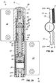
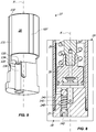
FIG. 1a is a top view of a first embodiment of thehinge device 1 in the completely closed position, with inFIG. 1b and FIG. 1c section views taken along respective planes Ib - I b and Ic - Ic; -
FIG. 2a is a top view of the embodiment of thehinge device 1 ofFIG. 1a in the completely open position, with inFIG. 2b a section view taken along a plane IIb - IIb; -
FIG. 3a is a top view of the embodiment of thehinge device 1 ofFIG. 1a in a position near to the closed one, with inFIG. 3b a section view taken along a plane IIIb - IIIb; -
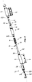
FIG. 4 is an exploded axonometric view of a further embodiment of thehinge device 1; -
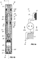
FIG. 5a is a top view of the embodiment of thehinge device 1 ofFIG. 4 in the completely closed position, with inFIG. 5b and FIG. 5c section views taken along respective planes Vb - Vb and Vc - Vc; -
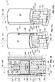
FIG. 6a is a top view of the embodiment of thehinge device 1 ofFIG. 4 in the completely open position, with inFIG. 6b a section view taken along a plane VIb - VIb; -
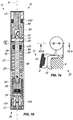
FIG. 7a is a top view of the embodiment of thehinge device 1 ofFIG. 4 in a position near to the closed one, with inFIG. 7b a section view taken along a plane VIIb - VIIb; -
FIG. 8 is an enlarged view of the details enclosed in the closed dotted line ofFIG. 1c ; -
FIG. 9 is an axonometric view of an embodiment of anend cap 27 that is cross sectioned to highlight the second overpressure valve means 140; -
FIG. 10 is an enlarged view of the details enclosed in the closed dotted line ofFIG. 1b ; -
FIGs. 11a and 11b are axonometric views of the embodiment of theend cap 27 ofFIG. 9 that are cross sectioned to highlight theducts - With reference to the above mentioned figures, the
hinge device 1 is particularly useful for rotatably moving and / or checking of a closing element D, such as a door, a shutter, a gate or the like, that may be anchored to a stationary support structure S, such as a wall and / or a frame of a door or of a window and / or a support column and / or the floor. - The
hinge device 1 is of hydraulic type. Depending on the configuration, and in particular on the presence or absence of the elastic counteracting means 40, thehinge device 1 may exclusively allow the checking upon the opening and / or closing of the closing element D to which it is coupled, or the latter action and the automatically closing of the closing element D thereof from the open position. - In the latter case, the elastic means 40 may include a thrust spring of relatively high power. However, the elastic means 40, although present, may include a counteracting spring of relatively low power, the power thereof not allowing the automatic closing action.
- In general, the
hinge device 1 includes a fixedelement 10 anchorable to the stationary support structure S and amovable element 11 that may be anchorable to the closing element D. - Preferably, the
hinge device 1 may be configured according to the teachings of one or more of the patent applicationsPCT/IB2012/051707 ,PCT/IB2013/059120 ,PCT/IB2013/059121 andVI2013A000245 - In particular, in a preferred but not exclusive embodiment, the fixed 10 and movable 11 elements of the
hinge device 1 may include ahinge body 18 with a respective first and second tubular half-shell FIGs. 2a and6a , and a closed position, shown for example inFIGs. 1a and5a . - Suitably, the fixed 10 and movable 11 elements may include a respective first and
second fastening wing shell - Preferably, the
hinge device 1 may be configured as a hinge of "anuba" type. - Advantageously, with the exception of the
fastening wings hinge device 1 may be included within the first and second tubular half-shell - The hinge comprises a working
chamber 20 defining the axis X and aplunger member 30 sliding therein. In particular, the first fixed tubular half-shell 12 may include the workingchamber 20. Suitably, the workingchamber 20 may be closed at the bottom with anend cap 27 inserted in the tubular half-shell 12. - Moreover, the working
chamber 20 includes a working fluid acting upon theplunger member 30 to hydraulically counteract the action thereof. In particular, the first fixed tubular half-shell 12 may include the working fluid, generally oil. Preferably, moreover, the first fixed tubular half-shell 12 may comprise elastic counteracting means 40, for example a compressinghelical spring 41, acting upon theplunger member thereof 30. - Suitably, externally to the working
chamber 20 and coaxially therewith apivot 50 is provided, that may advantageously act as an actuator, thepivot 50 may include anend portion 51 and atubular body 52. - In the preferred but not exclusive embodiment shown in
FIGs. 1a to 3b , thepivot 50 may be supported by theend portion 16 of the first fixed tubular half-shell 12. On the other hand, in the preferred but not exclusive embodiment shown inFIGs. 4 to 11b , thepivot 50 may be supported by asupport portion 84 manufactured in correspondence of theinner wall 83 of abushing 80, as explained hereinafter. - The
end portion 51 of thepivot 50 allows the coaxial coupling, preferably of removable type, between thepivot 50 thereof and the second movable tubular half-shell 13, so as the latter and thepivot 50 integrally rotate between the open and closed positions of the second movable tubular half-shell 13. - Suitably, the
plunger member 30 and thepivot 50 are operatively connected therebetween through the cylindricalelongated element 60, so as the rotation of the former around the axis X corresponds to the sliding of the latter along the axis X thereof and vice versa. - To the object, the cylindrical
elongated element 60 may include afirst end portion 61 reciprocally connected to theplunger member 30 and asecond end portion 62 sliding within thetubular body 52 of thepivot 50. - The connection between the cylindrical
elongated element 60 and theplunger member 30 may be susceptible to make the elements thereof integral, so as the same elements may define a slider movable along the axis X. - Therefore, the cylindrical
elongated element 60 may be slidable along the axis X integrally with theplunger member 30. Suitably, the cylindricalelongated element 60 and thepivot 50 may be coupled in a telescopic manner. - Furthermore, the cylindrical
elongated element 60 with therelative plunger member 30 may or may not be rotatably blocked in the workingchamber 20 to avoid rotations around the axis X during its sliding along the latter. This happens depending on the configuration of theguide cam slots 81 of thebushing 80. - Therefore, with respect to the
pivot 50, theplunger member 30 may slide along the axis X between an end-stroke position proximal thereto, corresponding to a one of the open and closed positions of the second movable tubular half-shell 13, and an end-stroke position distal from thepivot 50, corresponding to the other of the open and closed positions of the second movable tubular half-shell 13. - To allow the reciprocal movement between the
plunger member 30 and thepivot 50, thetubular body 52 of the latter may include at least one pair ofgrooves 70', 70" identical to each other angularly spaced by 180°, each one comprising at least one helical portion wound around the axis X. Thegrooves 70', 70" may be communicating with each other to define a single passing-throughactuator element 72. - Suitably, the at least one helical portion may have any angle, and may have right-handed trend, respectively left-handed trend. Preferably, the at least one helical portion may develop for at least 90° around the axis X, and even more preferably for at least 180°.
- In a preferred but not exclusive embodiment, each one of the
grooves 70', 70" may consists of a single helical portion, possibly with constant inclination or helical pitch. - Suitably, the
actuator element 72 may be closed at both ends so as to define a closed path having two blocking end points for thepin 73 sliding therethrough, the closed path being defined by thegrooves 70', 70". - Irrespective of its position or configuration, the passing-through
actuator element 72 rotating around the axis X allows the reciprocal movement between thepivot 50 and theplunger member 30. - To guide such a rotation, a
tubular guide bushing 80 may be provided coaxially placed outside thetubular body 52 of thepivot 50. Theguide bushing 80 may include a pair ofcam slots 81 angularly spaced by 180°. - To allow the reciprocal connection between the
pivot 50, theelongated element 60 and theguide bushing 80, thesecond end portion 62 of theelongated element 60 may include apin 73 inserted in the passing-throughactuator element 72 and in thecam slots 81 to slide therein. - Therefore, the length of the
pin 73 may be such as to allow this function. Therefore, upon the rotation of the passing-throughactuator element 72, thepin 73 is driven by the latter and guided by thecam slots 81. - Irrespective of the shape of the
cam slots 81, the latter may be closed at both ends so as to define a closed path having two blocking end points for thepin 73 sliding therethrough. - In order to minimize the friction between the moving parts, at least one anti-friction element may be provided, such as an
annular bearing 110, interposed between thepivot 50 and theend portion 16 of the first tubular half-shell 12 or between thepivot 50 thereof and thesupport portion 84 of thebushing 80. - In fact, as above mentioned, thanks to the above configuration the
pin 73 is pulled downwards, dragging therewith thepivot 50 that, therefore, rotates around the axis X on thebearing 110 with the minimum friction. - Furthermore, at least one further anti-friction element may be provided, for example a further
annular bearing 112, interposed between thebushing 80 and the second tubular half-shell 13, in such a way that the latter rotates around the axis X on thebearing 112. - Therefore, the
bearing 112 rests on the upper portion of thebushing 80, so as thepivot 50 is not affected by the weight of the closing element during its rotation around the axis X. - Preferably, moreover, the
bushing 80 and the second tubular half-shell 13 may be in a reciprocal spatial relationship such that the second tubular half-shell 13 once coupled with thebushing 80 remains spaced from the first tubular half-shell 12, for example at a distance equal to few tenths of a millimetre. - As above mentioned, the
hinge device 1 may include a working fluid, for example oil. - Advantageously, one or
more sealing elements 22 may be provided to avoid the discharge thereof, for example one or more o-rings. - The
plunger member 30 divides the workingchamber 20 in at least one first and one secondvariable volume compartment first compartment 23. - In a first preferred but not exclusive embodiment, the elastic counteracting means 40 may be interposed between the
pivot 50 and theplunger member 30. For example, the elastic counteracting means 40 may include a spring fitted over theelongated element 60. - To allow the passage of the working fluid between the first and the
second compartment plunger member 30 comprises valve means, that may include adisk 33 inserted with minimal play in asuitable house 34 to axially move along axis X. The assembly disk 33 -house 34 defines a non-return valve susceptible to intercept the working fluid. Eventually theplunger member 30 may include a passing-throughopening 31. - Depending on the direction to which the non-return valve is assembled, it may open upon the opening or closing of the closing element D, so as to allow the passage of the working fluid between the
first compartment 23 and thesecond compartment 24 during one of the opening or closing of the closing element D and to prevent the backflow thereof during the other of the opening or closing thereof. - For the controlled backflow of the working fluid between the
first compartment 23 and thesecond compartment 24 during the other of the opening or closing of the closing element D, a suitable hydraulic circuit 100 is provided. - Suitably, the
plunger member 30 may include, respectively consist of, a cylindrical body tightly inserted in the workingchamber 20 and faced to the inner side wall 25 thereof. - In general, the hydraulic circuit 100 may include a
channel 107 with anopening 102 in thefirst compartment 23. - Furthermore, the hydraulic circuit 100 includes a
duct 120 passing through theend cap 27 that includes anopening 121 fluidly communicating with theopening 102 and anopening 122 fluidly communicating with thesecond compartment 24. - Moreover, the hydraulic circuit 100 further includes a
duct 150 passing through theend cap 27 that, as better explained hereinafter, is fluidly connected with theduct 120. - Furthermore, the hydraulic circuit 100 may include a
duct 130 passing through theend cap 27 thereof to put in fluid communication thefirst compartment 23 and thesecond compartment 24. - Suitably, the
end cap 27 may further include valve means 140 acting upon theduct 130 to selectively open upon the passage of the working fluid through thechannel 107 when the pressure PC in the workingchamber 20 exceeds a predetermined threshold value PT. - To protect the entirety of the closing element D that assembles the
hinge device 1, the threshold pressure value PT may be calibrated in order to avoid the unhinging of the closing element D thereof by a user that forces the opening and / or closing. - From the constructive point of view, the valve means 140 may include a
shutter element 141 acting upon theduct 130, and more precisely upon theoutlet 135 thereof, andelastic means 142 acting thereon. Both theshutter element 141 and theelastic means 142 may be inserted in theduct 130 and closed by thegrub screw 143. - Advantageously, the
elastic means 142 may be selected to provide the threshold pressure value PT. - On the other hand, the
screw 143 may be one adjusting screw movable from outside by a user to act upon the secondelastic means 142, so as to vary the action thereof on saidshutter element 141 thus adjusting the predetermined threshold pressure value PT. - From an operational point of view, the valve means 140 may be closed when the pressure PC in the working
chamber 20 is below the threshold value PT to prevent the passage of the working fluid through theduct 130, so as to force the passage thereof through theduct 120. - Advantageously, the threshold pressure value PT may be greater than the maximum pressure PCmax imparted in the working
chamber 20 by the elastic counteracting means 40. Preferably, the threshold pressure value PT is greater than the maximum pressure PCmax of a percentage of 15% to 30%. - The
end cap 27 includes an elongatedtubular wall 28 extending within the workingchamber 20. The hydraulic circuit 100 includes the interspace between the workingchamber 20 and the elongatedtubular wall 28 of theend cap 27. - Suitably, the elongated
tubular wall 28 may be tightly inserted in the workingchamber 20, while theplunger member 30 may be tightly inserted in the elongatedtubular wall 28. - Preferably, the length of the latter may be equal to or greater than the stroke of the plunger member, so as the
second compartment 24 is defined within the elongatedtubular wall 28. More particularly, thesecond compartment 24 may have an upper wall defined by theplunger member 30, a bottom wall defined by thecap 27 and a side wall defined by the elongatedtubular wall 28 of thecap 27 thereof. - Preferably, the elongated
tubular wall 28 may be monolithically coupled with theend cap 27 so as the screwing of the latter in thehinge body 18 defines the hydraulic circuit 100, so as the latter consists exclusively of the interspace between the workingchamber 20 and the elongatedtubular wall 28 and of theducts - The elongated
tubular wall 28 of theend cap 27 may include a peripheral conduit defining thechannel 107, a peripheral conduit defining afurther channel 131 and afurther conduit 160. - Suitably, both
conduits conduit 160 is a blind conduit. - The
conduit 107 may have a port defining theopening 102 and aport 108 in fluid communication with theopening 121, and, therefore, with thevariable volume compartment 24 through theduct 120. More particularly, the latter may include twobranches port 108 and the second 123 in fluid communication with thecompartment 24 through thecollector 122, whose function is better explained hereinafter. - The
conduit 131 may have aport 132 in the firstvariable volume compartment 23 and aport 133 in fluid communication with thevariable volume compartment 24 through theduct 130. The latter may have abranch 134 and anopening 135, wherebetween the valve means 140 may be placed. - The
conduit 160 may have aport 161 and aport 162 in fluid communication with thevariable volume compartment 24 through theduct 150. More particularly, the latter may include twobranches port 162 and the second 152 in fluid communication with thecompartment 24 through thecollector 122. - As above mentioned, the
duct 130 in cooperation with the valve means 140 defines a overpressure valve. - On the other hand, in the
ducts members end ducts end - Advantageously, the
ends - Since the
plunger member 30, the elongatedtubular wall 28 and the workingchamber 20 are tightly inserted one inside the other, the assemblies conduit 107 -duct 120, conduit 130 -duct 131 and conduit 160 -duct 150 define respective hydraulic circuits independent between them. - Although in the annexed figures the two adjusting members are substantially parallel to the axis X, they may also be substantially perpendicular thereto without departing from the scope of the appended claims.
- In case the valve means 32 are configured to open upon the passage of the working fluid from the
first compartment 23 to thesecond compartment 24 and to close upon the opposite passage so as to force the working fluid to pass through the hydraulic circuit 100, thebranches ducts branches outlet branches ports conduits variable volume compartment 23 through theports - When the working
chamber 20 is pressurized, for example during the opening of the door, the valve means 32 open to let the working fluid flow from thefirst compartment 23 to thesecond compartment 24. On the other hand, during the closing of the door the valve means 23 close, forcing the working fluid from thecompartment 24 to thecentral collector 122, and here-hence to theinlet branches - Therefore, the
central collector 122 collects the working fluid coming from thecompartment 24 and distributes it to the twobranches central collector 122 may be placed along the axis X, while the adjustingmembers - Moreover, the
duct 130 may be misaligned with respect to the twoducts - This allows to have the two adjusting
members - Suitably, the
inlet branches ends members outlet branches respective ducts - In a preferred but not exclusive embodiment, the
plunger member 30, theconduit 107 and theconduit 160 may be reciprocally configured so as theport 102 remains fluidly free throughout the stroke of theplunger member 30 and so as theport 161 remains fluidly blocked for a part of the stroke of theplunger member 30 and fluidly free for a second part of the stroke thereof near the open or closed position of the closing element D, so as the latter snap fits towards the open or closed position thereof. - Therefore, the adjusting
member 103 may be susceptible to adjust the speed upon the closing or opening of the closing element D, while the adjustingmember 170 may be susceptible to adjust the force of the snap-fit of the closing element D towards the closed or open position. - For the aforementioned, the
end cap 27 allows to provide an extremely safe hinge device thanks to the overpressure valve means 140 and easily adjustable both in speed and in snap-fit thanks to the adjustingmembers - From the above description, it is evident that the invention fulfils the intended objects.
- The invention is susceptible of numerous modifications and variations, all falling within the inventive concept expressed in the accompanying claims. All particulars may be replaced with other technically equivalent elements, and the materials may be different according to requirements, without departing from the scope of the invention defined by the appended claims.
Claims (12)
- Hinge device for rotatably moving and / or checking during the opening and / or closing a closing element (D), such as a door, a shutter or the like, anchored to a stationary support structure (S), such as a wall or a frame, the device including:- a fixed element (10) anchorable to the stationary support structure (S);- a movable element (11) anchorable to the closing element (D), said movable element (11) and said fixed element (10) being reciprocally coupled to rotate around a first longitudinal axis (X) between an open position and a closed position;- at least one slider (30, 60) movable along a second axis (X) between a first end-stroke position, corresponding to one of said open and closed positions, and a second end-stroke position, corresponding to the other of said open and closed positions;wherein one of said fixed element (10) and said movable element (11) comprises at least one working chamber (20) defining said second longitudinal axis (X) to slidably house said at least one slider (30, 60), the other of said fixed element (10) and said movable element (11) comprising a pivot (50) defining said first axis (X), said pivot (50) and said at least one slider (30, 60) being reciprocally coupled so as the rotation of the movable element (11) around said first axis (X) corresponds to the at least partial sliding of the at least one slider (30, 60) along said second axis (X) and vice-versa, said at least one working chamber (20) including at least one end cap (27);
wherein said at least one working chamber (20) includes a working fluid acting upon said at least one slider (30, 60) to hydraulically counteract the action thereof, said at least one slider (30, 60) including a plunger member (30) that divides said working chamber (20) in at least one first and one second variable volume compartments (23, 24) fluidly communicating therebetween and preferably adjacent to each other, said plunger member (30) comprising first valve means (32) to allow the passage of the working fluid between said first compartment (23) and said second compartment (24) during one of the opening or closing of the closing element (D) and to prevent the passage thereof during the other of the opening or closing thereof, a hydraulic circuit (100) being further provided to allow the passage of the working fluid between said first compartment (23) and said second compartment (24) during the other of the opening or closing of the closing element (D);
wherein said hydraulic circuit (100) includes at least one first duct (120) passing through said at least one end cap (27) in fluid communication with both said first compartment (23) and said second compartment (24), said at least one end cap (27) further including at least one first adjusting member (103) having a first end (104) interacting with said at least one first duct (120) and a second end (105) controllable from the outside by a user to adjust the passage section of the working fluid passing therethrough; wherein said at least one end cap (27) includes an elongated tubular wall (28) extending within said at least one working chamber (20), said hydraulic circuit (100) including the interspace between said working chamber (20) and said elongated tubular wall (28); in such a manner that the hydraulic circuit is entirely defined by the end cap, the working chamber being free of channels or ducts,
characterised in that said hydraulic circuit (100) includes a second duct (150) passing through said at least one end cap (27) in fluid communication with both said first compartment (23) and said second compartment (24), said at least one end cap (27) further including at least one second adjusting member (170) having a third end (171) interacting with said at least one second duct (150) and a fourth end (172) controllable from the outside by a user to adjust the passage section of the working fluid passing therethrough. - Device according to the preceding claim, wherein said elongated tubular wall (28) is tightly inserted in said at least one working chamber (20), said plunger member (30) being tightly inserted into said elongated tubular wall (28), the latter including at least one first peripheral conduit (107) having a first port (102) in one of said first compartment (23) and said second compartment (24) and a second port (108) in fluid communication with the other of said first compartment (23) and said second compartment (24) through said at least one first duct (120).
- Device according to any one of the preceding claims, wherein said elongated tubular wall (28) is monolithically coupled with said at least one end cap (27) so as the coupling of the latter with said at least one working chamber (20) defines said hydraulic circuit (100), so as the latter consists exclusively of said interspace between said working chamber (20) and said elongated tubular wall (28) and of said at least one first duct (120) passing through said at least one end cap (27).
- Device according to any one of the preceding claims, wherein said first valve means (32) are configured to open upon the passage of the working fluid from said first compartment (23) to said second compartment (24) and to close upon the passage thereof from said second compartment (24) to said first compartment (23) so as to force the working fluid to flow through said hydraulic circuit (100).
- Device according to the preceding claim, wherein said first end (104) of said at least one first adjusting member (103) has a substantially frustoconical shape, said at least one first duct (120) including a first inlet branch (121) and a first outlet branch (123) both faced to said first end (104) of said at least one first adjusting member (103), said first inlet branch (121) being faced to a portion of said first end (104) of said at least one first adjusting member (103) having a section greater than the one to which said first outlet branch is faced so as to minimize or eliminate variations in the flow of said working fluid.
- Device according to the preceding claim, wherein said at least one plunger member (30) and said first conduit (107) are reciprocally configured so as said first port (102) remains fluidly free for the entire stroke of said at least one plunger member (30), so as said at least one first adjusting member (103) is susceptible to adjust the speed upon the closing or opening of said closing element (D).
- Device according to any one of the preceding claims, wherein said at least one first duct (120) and second duct (150) are in fluid communication with a single central collector (122) placed along said first axis (X), said at least one first adjusting member (103) and at least one second adjusting member (170) being placed on opposite sides with respect to a median plane (πM) passing through said first axis (X).
- Device according to any one of the preceding claims, wherein said elongated tubular wall (28) includes a second peripheral conduit (160) having a third port (161) in said one of said first compartment (23) and said second compartment (24) and a fourth port (162) in fluid communication with the other of said first compartment (23) and said second compartment (24) through said at least one second duct (150).
- Device according to the preceding claim, wherein said at least one plunger member (30) and said second peripheral conduit (160) are reciprocally configured so as said third port (161) remains fluidly blocked for a part of the stroke of said at least one plunger member (30) and fluidly free for a second part of the stroke thereof, said third port (161) being in a spatial relationship with said plunger member so as to remain fluidly free near the open or closed position of the closing element (D) so as the latter snap-fits towards the open or closed position thereof, so as said second adjustment member (170) is susceptible to adjust the force of the snap-fit of said closing element (D) towards the closed or open position.
- Device according to any one of the preceding claims, wherein said third end (171) of said at least one second adjusting member (170) has a substantially frustoconical shape, said at least one second duct (150) including a second inlet branch (151) and a second outlet branch (152) both faced to said third end (171) of said at least one second adjusting member (170), said second inlet branch (151) being faced to a portion of said third end (171) of said at least one second adjusting member (170) having a section greater than the one to which said second outlet branch (152) is faced so as to minimize or eliminate variations in the flow of said working fluid.
- Device according to the preceding claim, wherein said first and second inlet branch (121, 151), respectively said first and second outlet branch (123, 152), are reciprocally faced to merge in said single central collector (122) susceptible to put the same branches in fluid communication with said other of said first compartment (23) and said second compartment (24), said first and second outlet branch (123, 152), respectively said first and second inlet branch (121, 151), being both in fluid communication with said one of said first compartment (23) and said second compartment (24).
- Device according to any one of the preceding claims, wherein said hydraulic circuit (100) further includes a third duct (130) passing through said at least one end cap (27) in fluid communication with both said first compartment (23) and said second compartment (24), said elongated tubular wall (28) including a third peripheral conduit (131) having a fifth port (132) in one of said first compartment (23) and said second compartment (24) and a sixth port (133) in fluid communication with the other of said first compartment (23) and said second compartment (24) through said third duct (130), said at least one end cap (27) further including second valve means (140) acting upon said third duct (130) to selectively open upon the passage of the working fluid through said at least one first peripheral conduit (107) when the pressure (PC) in said at least one working chamber (20) exceeds a predetermined threshold value (PT), said third duct (130) being misaligned with respect to said at least one first duct (120) and second duct (150).
Applications Claiming Priority (3)
| Application Number | Priority Date | Filing Date | Title |
|---|---|---|---|
| ITVI20140256 | 2014-10-06 | ||
| ITVI20140257 | 2014-10-06 | ||
| PCT/IB2015/057625 WO2016055929A1 (en) | 2014-10-06 | 2015-10-06 | Hinge device for doors, shutters or the like |
Publications (2)
| Publication Number | Publication Date |
|---|---|
| EP3204582A1 EP3204582A1 (en) | 2017-08-16 |
| EP3204582B1 true EP3204582B1 (en) | 2019-12-11 |
Family
ID=54542297
Family Applications (1)
| Application Number | Title | Priority Date | Filing Date |
|---|---|---|---|
| EP15794639.3A Active EP3204582B1 (en) | 2014-10-06 | 2015-10-06 | Hinge device for doors, shutters or the like |
Country Status (8)
| Country | Link |
|---|---|
| US (1) | US9926732B2 (en) |
| EP (1) | EP3204582B1 (en) |
| JP (1) | JP2017534780A (en) |
| CN (1) | CN107109878B (en) |
| BR (1) | BR112017007038A2 (en) |
| CA (1) | CA2963453A1 (en) |
| EA (1) | EA031642B1 (en) |
| WO (1) | WO2016055929A1 (en) |
Families Citing this family (12)
| Publication number | Priority date | Publication date | Assignee | Title |
|---|---|---|---|---|
| UA115453C2 (en) * | 2012-10-04 | 2017-11-10 | Ін Енд Тек С.Р.Л. | Hinge device for doors, shutters and the like |
| EP3456908A4 (en) * | 2016-05-12 | 2020-01-08 | Firstcloser. Co. Ltd | Closer apparatus |
| WO2018121890A1 (en) * | 2016-12-27 | 2018-07-05 | Locinox | A hydraulically damped actuator |
| EP3342965A1 (en) * | 2016-12-27 | 2018-07-04 | Locinox | Hydraulically damped, self closing hinge |
| US10633905B2 (en) | 2017-02-20 | 2020-04-28 | Huaigang Feng | Combined door hinge with variable hydraulic damping and stopper device performance |
| CN110785534B (en) * | 2017-06-16 | 2022-03-29 | 洛西诺克斯公司 | Hydraulic damping actuator |
| CN109812164A (en) * | 2017-11-20 | 2019-05-28 | 富泰华工业(深圳)有限公司 | Damping rotation shaft with unidirectionally pivoting feedback |
| DE102018003920A1 (en) * | 2018-05-16 | 2019-11-21 | Günther Zimmer | Hinge with multi-level opening |
| IT201900004791A1 (en) * | 2019-03-29 | 2020-09-29 | Colcom Group S P A | HINGE DEVICE FOR GLASS DOORS OR SIMILAR |
| TWI722441B (en) * | 2019-05-27 | 2021-03-21 | 陳旺松 | Combined hinge and hydraulic device |
| DE102019209567B4 (en) * | 2019-06-28 | 2022-10-06 | Geze Gmbh | Door closer and method of assembling and adjusting a door closer |
| US11047162B1 (en) | 2020-03-03 | 2021-06-29 | Leonard Tennessee | Torsion spring door closing apparatus |
Family Cites Families (23)
| Publication number | Priority date | Publication date | Assignee | Title |
|---|---|---|---|---|
| GB396673A (en) * | 1930-11-19 | 1933-08-10 | Antoine Thuillier | Improvements relating to door-closing devices |
| US2118950A (en) * | 1936-05-20 | 1938-05-31 | Leavelle Ab | Closure controlling device |
| US2127327A (en) * | 1936-07-23 | 1938-08-16 | Dutee W Flint | Automatic door check construction |
| US2164358A (en) * | 1937-01-22 | 1939-07-04 | Leavelle Ab | Closure controlling device |
| US2456537A (en) * | 1944-08-07 | 1948-12-14 | Seaman | Hydraulic door check |
| US4103392A (en) * | 1976-10-26 | 1978-08-01 | Masco Corporation | Door closing apparatus |
| JPS5724839Y2 (en) * | 1977-03-19 | 1982-05-29 | ||
| US4485522A (en) * | 1982-08-31 | 1984-12-04 | Chen Youn Long | Door-closing hinge having a spring and pin mechanism |
| US5152029A (en) * | 1991-08-12 | 1992-10-06 | King Chain Precision Industry Co., Ltd. | Hydraulic hinge |
| US6205619B1 (en) * | 1998-09-17 | 2001-03-27 | Jang Jong-Bok | Hydraulic automatic-shock-absorbing hinge device |
| JP3045290B2 (en) * | 1998-10-19 | 2000-05-29 | ボク ジャン ジョン | Hydraulic automatic buffer hinge |
| US6928699B2 (en) * | 2001-01-15 | 2005-08-16 | Masako Sawa | Automatic closing door hinge, automatic closing door mechanism, and hinge of automatic closing door mechanism |
| KR100403366B1 (en) * | 2001-01-17 | 2003-10-30 | 주식회사 솔텍 | Open & close damping device of door |
| US7155776B2 (en) * | 2003-06-10 | 2007-01-02 | I-One Innotech Co., Ltd. | Multipurpose hinge apparatus having automatic return function |
| KR100586262B1 (en) * | 2004-08-24 | 2006-06-07 | 주식회사 아이원이노텍 | Hinge Apparatus for Heavy Door Having Automatic Return Function |
| KR100835730B1 (en) | 2005-07-29 | 2008-06-05 | 주식회사 아이원이노텍 | Ball Type Clutch Apparatus and Hinge Apparatus Having Automatic Return Function Using the Same |
| KR100761904B1 (en) * | 2006-08-08 | 2007-09-28 | 주식회사 아이원이노텍 | Hinge apparatus having automatic return function for use in building materials |
| JP4651684B2 (en) * | 2008-02-05 | 2011-03-16 | 株式会社サワ | Automatic door hinge for double opening and double door structure |
| JP4864944B2 (en) * | 2008-07-14 | 2012-02-01 | 株式会社Lixil | Door closer |
| EP2295693A1 (en) * | 2009-08-27 | 2011-03-16 | Joseph Talpe | Door closing mechanism |
| WO2012137042A1 (en) * | 2011-04-05 | 2012-10-11 | In & Tec S.R.L. | Hinge device for doors, shutters or the like |
| TW201402928A (en) * | 2012-07-06 | 2014-01-16 | Leado Door Controls Ltd | Automatic return device for glass door |
| CN203271390U (en) * | 2013-05-28 | 2013-11-06 | 宁波市五角阻尼科技有限公司 | Hydraulic buffering hinge capable of automatically closing door |
-
2015
- 2015-10-06 EP EP15794639.3A patent/EP3204582B1/en active Active
- 2015-10-06 CN CN201580054476.6A patent/CN107109878B/en active Active
- 2015-10-06 US US15/515,721 patent/US9926732B2/en not_active Expired - Fee Related
- 2015-10-06 CA CA2963453A patent/CA2963453A1/en not_active Abandoned
- 2015-10-06 EA EA201790808A patent/EA031642B1/en not_active IP Right Cessation
- 2015-10-06 JP JP2017517306A patent/JP2017534780A/en not_active Ceased
- 2015-10-06 WO PCT/IB2015/057625 patent/WO2016055929A1/en active Application Filing
- 2015-10-06 BR BR112017007038A patent/BR112017007038A2/en not_active Application Discontinuation
Non-Patent Citations (1)
| Title |
|---|
| None * |
Also Published As
| Publication number | Publication date |
|---|---|
| EA031642B1 (en) | 2019-01-31 |
| EP3204582A1 (en) | 2017-08-16 |
| BR112017007038A2 (en) | 2018-01-30 |
| CA2963453A1 (en) | 2016-04-14 |
| US20170241180A1 (en) | 2017-08-24 |
| CN107109878A (en) | 2017-08-29 |
| JP2017534780A (en) | 2017-11-24 |
| CN107109878B (en) | 2019-01-08 |
| EA201790808A1 (en) | 2017-07-31 |
| US9926732B2 (en) | 2018-03-27 |
| WO2016055929A1 (en) | 2016-04-14 |
Similar Documents
| Publication | Publication Date | Title |
|---|---|---|
| EP3204582B1 (en) | Hinge device for doors, shutters or the like | |
| US10760316B2 (en) | Hinge device for doors, shutters and the like | |
| US9353564B2 (en) | Hinge device for doors, shutters or the like | |
| US9605462B2 (en) | Hinge device for doors, shutters and the like | |
| EP3640421A1 (en) | Low-bulkiness hydraulic hinge | |
| EP2877662B1 (en) | Hinge for the rotatable movement of a door, a door leaf or the like | |
| EP3052730B1 (en) | Hinge device for doors, shutters or the like | |
| EP3440296B1 (en) | Hinge device for doors, shutters or the like | |
| ITVI20120249A1 (en) | HINGE DEVICE FOR DOORS, DOORS OR SIMILARS |
Legal Events
| Date | Code | Title | Description |
|---|---|---|---|
| STAA | Information on the status of an ep patent application or granted ep patent |
Free format text: STATUS: THE INTERNATIONAL PUBLICATION HAS BEEN MADE |
|
| PUAI | Public reference made under article 153(3) epc to a published international application that has entered the european phase |
Free format text: ORIGINAL CODE: 0009012 |
|
| STAA | Information on the status of an ep patent application or granted ep patent |
Free format text: STATUS: REQUEST FOR EXAMINATION WAS MADE |
|
| 17P | Request for examination filed |
Effective date: 20170508 |
|
| AK | Designated contracting states |
Kind code of ref document: A1 Designated state(s): AL AT BE BG CH CY CZ DE DK EE ES FI FR GB GR HR HU IE IS IT LI LT LU LV MC MK MT NL NO PL PT RO RS SE SI SK SM TR |
|
| AX | Request for extension of the european patent |
Extension state: BA ME |
|
| DAV | Request for validation of the european patent (deleted) | ||
| DAX | Request for extension of the european patent (deleted) | ||
| STAA | Information on the status of an ep patent application or granted ep patent |
Free format text: STATUS: EXAMINATION IS IN PROGRESS |
|
| 17Q | First examination report despatched |
Effective date: 20180606 |
|
| GRAP | Despatch of communication of intention to grant a patent |
Free format text: ORIGINAL CODE: EPIDOSNIGR1 |
|
| STAA | Information on the status of an ep patent application or granted ep patent |
Free format text: STATUS: GRANT OF PATENT IS INTENDED |
|
| INTG | Intention to grant announced |
Effective date: 20190605 |
|
| GRAS | Grant fee paid |
Free format text: ORIGINAL CODE: EPIDOSNIGR3 |
|
| GRAA | (expected) grant |
Free format text: ORIGINAL CODE: 0009210 |
|
| STAA | Information on the status of an ep patent application or granted ep patent |
Free format text: STATUS: THE PATENT HAS BEEN GRANTED |
|
| AK | Designated contracting states |
Kind code of ref document: B1 Designated state(s): AL AT BE BG CH CY CZ DE DK EE ES FI FR GB GR HR HU IE IS IT LI LT LU LV MC MK MT NL NO PL PT RO RS SE SI SK SM TR |
|
| REG | Reference to a national code |
Ref country code: GB Ref legal event code: FG4D |
|
| REG | Reference to a national code |
Ref country code: CH Ref legal event code: EP |
|
| REG | Reference to a national code |
Ref country code: AT Ref legal event code: REF Ref document number: 1212336 Country of ref document: AT Kind code of ref document: T Effective date: 20191215 |
|
| REG | Reference to a national code |
Ref country code: DE Ref legal event code: R096 Ref document number: 602015043549 Country of ref document: DE |
|
| REG | Reference to a national code |
Ref country code: IE Ref legal event code: FG4D |
|
| REG | Reference to a national code |
Ref country code: NL Ref legal event code: MP Effective date: 20191211 |
|
| REG | Reference to a national code |
Ref country code: LT Ref legal event code: MG4D |
|
| PG25 | Lapsed in a contracting state [announced via postgrant information from national office to epo] |
Ref country code: LT Free format text: LAPSE BECAUSE OF FAILURE TO SUBMIT A TRANSLATION OF THE DESCRIPTION OR TO PAY THE FEE WITHIN THE PRESCRIBED TIME-LIMIT Effective date: 20191211 Ref country code: FI Free format text: LAPSE BECAUSE OF FAILURE TO SUBMIT A TRANSLATION OF THE DESCRIPTION OR TO PAY THE FEE WITHIN THE PRESCRIBED TIME-LIMIT Effective date: 20191211 Ref country code: GR Free format text: LAPSE BECAUSE OF FAILURE TO SUBMIT A TRANSLATION OF THE DESCRIPTION OR TO PAY THE FEE WITHIN THE PRESCRIBED TIME-LIMIT Effective date: 20200312 Ref country code: NO Free format text: LAPSE BECAUSE OF FAILURE TO SUBMIT A TRANSLATION OF THE DESCRIPTION OR TO PAY THE FEE WITHIN THE PRESCRIBED TIME-LIMIT Effective date: 20200311 Ref country code: BG Free format text: LAPSE BECAUSE OF FAILURE TO SUBMIT A TRANSLATION OF THE DESCRIPTION OR TO PAY THE FEE WITHIN THE PRESCRIBED TIME-LIMIT Effective date: 20200311 Ref country code: SE Free format text: LAPSE BECAUSE OF FAILURE TO SUBMIT A TRANSLATION OF THE DESCRIPTION OR TO PAY THE FEE WITHIN THE PRESCRIBED TIME-LIMIT Effective date: 20191211 Ref country code: LV Free format text: LAPSE BECAUSE OF FAILURE TO SUBMIT A TRANSLATION OF THE DESCRIPTION OR TO PAY THE FEE WITHIN THE PRESCRIBED TIME-LIMIT Effective date: 20191211 |
|
| PG25 | Lapsed in a contracting state [announced via postgrant information from national office to epo] |
Ref country code: RS Free format text: LAPSE BECAUSE OF FAILURE TO SUBMIT A TRANSLATION OF THE DESCRIPTION OR TO PAY THE FEE WITHIN THE PRESCRIBED TIME-LIMIT Effective date: 20191211 Ref country code: HR Free format text: LAPSE BECAUSE OF FAILURE TO SUBMIT A TRANSLATION OF THE DESCRIPTION OR TO PAY THE FEE WITHIN THE PRESCRIBED TIME-LIMIT Effective date: 20191211 |
|
| PG25 | Lapsed in a contracting state [announced via postgrant information from national office to epo] |
Ref country code: AL Free format text: LAPSE BECAUSE OF FAILURE TO SUBMIT A TRANSLATION OF THE DESCRIPTION OR TO PAY THE FEE WITHIN THE PRESCRIBED TIME-LIMIT Effective date: 20191211 |
|
| PG25 | Lapsed in a contracting state [announced via postgrant information from national office to epo] |
Ref country code: NL Free format text: LAPSE BECAUSE OF FAILURE TO SUBMIT A TRANSLATION OF THE DESCRIPTION OR TO PAY THE FEE WITHIN THE PRESCRIBED TIME-LIMIT Effective date: 20191211 Ref country code: ES Free format text: LAPSE BECAUSE OF FAILURE TO SUBMIT A TRANSLATION OF THE DESCRIPTION OR TO PAY THE FEE WITHIN THE PRESCRIBED TIME-LIMIT Effective date: 20191211 Ref country code: EE Free format text: LAPSE BECAUSE OF FAILURE TO SUBMIT A TRANSLATION OF THE DESCRIPTION OR TO PAY THE FEE WITHIN THE PRESCRIBED TIME-LIMIT Effective date: 20191211 Ref country code: RO Free format text: LAPSE BECAUSE OF FAILURE TO SUBMIT A TRANSLATION OF THE DESCRIPTION OR TO PAY THE FEE WITHIN THE PRESCRIBED TIME-LIMIT Effective date: 20191211 Ref country code: CZ Free format text: LAPSE BECAUSE OF FAILURE TO SUBMIT A TRANSLATION OF THE DESCRIPTION OR TO PAY THE FEE WITHIN THE PRESCRIBED TIME-LIMIT Effective date: 20191211 Ref country code: PT Free format text: LAPSE BECAUSE OF FAILURE TO SUBMIT A TRANSLATION OF THE DESCRIPTION OR TO PAY THE FEE WITHIN THE PRESCRIBED TIME-LIMIT Effective date: 20200506 |
|
| PG25 | Lapsed in a contracting state [announced via postgrant information from national office to epo] |
Ref country code: SM Free format text: LAPSE BECAUSE OF FAILURE TO SUBMIT A TRANSLATION OF THE DESCRIPTION OR TO PAY THE FEE WITHIN THE PRESCRIBED TIME-LIMIT Effective date: 20191211 Ref country code: SK Free format text: LAPSE BECAUSE OF FAILURE TO SUBMIT A TRANSLATION OF THE DESCRIPTION OR TO PAY THE FEE WITHIN THE PRESCRIBED TIME-LIMIT Effective date: 20191211 Ref country code: IS Free format text: LAPSE BECAUSE OF FAILURE TO SUBMIT A TRANSLATION OF THE DESCRIPTION OR TO PAY THE FEE WITHIN THE PRESCRIBED TIME-LIMIT Effective date: 20200411 |
|
| REG | Reference to a national code |
Ref country code: DE Ref legal event code: R097 Ref document number: 602015043549 Country of ref document: DE |
|
| REG | Reference to a national code |
Ref country code: AT Ref legal event code: MK05 Ref document number: 1212336 Country of ref document: AT Kind code of ref document: T Effective date: 20191211 |
|
| PLBE | No opposition filed within time limit |
Free format text: ORIGINAL CODE: 0009261 |
|
| STAA | Information on the status of an ep patent application or granted ep patent |
Free format text: STATUS: NO OPPOSITION FILED WITHIN TIME LIMIT |
|
| PG25 | Lapsed in a contracting state [announced via postgrant information from national office to epo] |
Ref country code: DK Free format text: LAPSE BECAUSE OF FAILURE TO SUBMIT A TRANSLATION OF THE DESCRIPTION OR TO PAY THE FEE WITHIN THE PRESCRIBED TIME-LIMIT Effective date: 20191211 |
|
| 26N | No opposition filed |
Effective date: 20200914 |
|
| PG25 | Lapsed in a contracting state [announced via postgrant information from national office to epo] |
Ref country code: AT Free format text: LAPSE BECAUSE OF FAILURE TO SUBMIT A TRANSLATION OF THE DESCRIPTION OR TO PAY THE FEE WITHIN THE PRESCRIBED TIME-LIMIT Effective date: 20191211 Ref country code: SI Free format text: LAPSE BECAUSE OF FAILURE TO SUBMIT A TRANSLATION OF THE DESCRIPTION OR TO PAY THE FEE WITHIN THE PRESCRIBED TIME-LIMIT Effective date: 20191211 |
|
| PG25 | Lapsed in a contracting state [announced via postgrant information from national office to epo] |
Ref country code: PL Free format text: LAPSE BECAUSE OF FAILURE TO SUBMIT A TRANSLATION OF THE DESCRIPTION OR TO PAY THE FEE WITHIN THE PRESCRIBED TIME-LIMIT Effective date: 20191211 |
|
| PG25 | Lapsed in a contracting state [announced via postgrant information from national office to epo] |
Ref country code: LU Free format text: LAPSE BECAUSE OF NON-PAYMENT OF DUE FEES Effective date: 20201006 Ref country code: MC Free format text: LAPSE BECAUSE OF FAILURE TO SUBMIT A TRANSLATION OF THE DESCRIPTION OR TO PAY THE FEE WITHIN THE PRESCRIBED TIME-LIMIT Effective date: 20191211 |
|
| REG | Reference to a national code |
Ref country code: BE Ref legal event code: MM Effective date: 20201031 |
|
| PG25 | Lapsed in a contracting state [announced via postgrant information from national office to epo] |
Ref country code: BE Free format text: LAPSE BECAUSE OF NON-PAYMENT OF DUE FEES Effective date: 20201031 |
|
| PG25 | Lapsed in a contracting state [announced via postgrant information from national office to epo] |
Ref country code: IE Free format text: LAPSE BECAUSE OF NON-PAYMENT OF DUE FEES Effective date: 20201006 |
|
| PG25 | Lapsed in a contracting state [announced via postgrant information from national office to epo] |
Ref country code: TR Free format text: LAPSE BECAUSE OF FAILURE TO SUBMIT A TRANSLATION OF THE DESCRIPTION OR TO PAY THE FEE WITHIN THE PRESCRIBED TIME-LIMIT Effective date: 20191211 Ref country code: MT Free format text: LAPSE BECAUSE OF FAILURE TO SUBMIT A TRANSLATION OF THE DESCRIPTION OR TO PAY THE FEE WITHIN THE PRESCRIBED TIME-LIMIT Effective date: 20191211 Ref country code: CY Free format text: LAPSE BECAUSE OF FAILURE TO SUBMIT A TRANSLATION OF THE DESCRIPTION OR TO PAY THE FEE WITHIN THE PRESCRIBED TIME-LIMIT Effective date: 20191211 |
|
| PG25 | Lapsed in a contracting state [announced via postgrant information from national office to epo] |
Ref country code: MK Free format text: LAPSE BECAUSE OF FAILURE TO SUBMIT A TRANSLATION OF THE DESCRIPTION OR TO PAY THE FEE WITHIN THE PRESCRIBED TIME-LIMIT Effective date: 20191211 |
|
| P01 | Opt-out of the competence of the unified patent court (upc) registered |
Effective date: 20230615 |
|
| PGFP | Annual fee paid to national office [announced via postgrant information from national office to epo] |
Ref country code: GB Payment date: 20231017 Year of fee payment: 9 |
|
| PGFP | Annual fee paid to national office [announced via postgrant information from national office to epo] |
Ref country code: IT Payment date: 20231026 Year of fee payment: 9 Ref country code: FR Payment date: 20231010 Year of fee payment: 9 Ref country code: DE Payment date: 20231012 Year of fee payment: 9 Ref country code: CH Payment date: 20231102 Year of fee payment: 9 |