EP3204295B1 - Disposition en arêtes de poisson en paire de sièges de première classe à haute densité - Google Patents
Disposition en arêtes de poisson en paire de sièges de première classe à haute densité Download PDFInfo
- Publication number
- EP3204295B1 EP3204295B1 EP15784242.8A EP15784242A EP3204295B1 EP 3204295 B1 EP3204295 B1 EP 3204295B1 EP 15784242 A EP15784242 A EP 15784242A EP 3204295 B1 EP3204295 B1 EP 3204295B1
- Authority
- EP
- European Patent Office
- Prior art keywords
- aisle
- seating
- height
- column
- delineating
- Prior art date
- Legal status (The legal status is an assumption and is not a legal conclusion. Google has not performed a legal analysis and makes no representation as to the accuracy of the status listed.)
- Active
Links
- 230000003247 decreasing effect Effects 0.000 description 3
- UQMRAFJOBWOFNS-UHFFFAOYSA-N butyl 2-(2,4-dichlorophenoxy)acetate Chemical compound CCCCOC(=O)COC1=CC=C(Cl)C=C1Cl UQMRAFJOBWOFNS-UHFFFAOYSA-N 0.000 description 1
- 239000000969 carrier Substances 0.000 description 1
- 238000005516 engineering process Methods 0.000 description 1
- 230000002708 enhancing effect Effects 0.000 description 1
- 238000002955 isolation Methods 0.000 description 1
Images


Classifications
-
- B—PERFORMING OPERATIONS; TRANSPORTING
- B64—AIRCRAFT; AVIATION; COSMONAUTICS
- B64D—EQUIPMENT FOR FITTING IN OR TO AIRCRAFT; FLIGHT SUITS; PARACHUTES; ARRANGEMENTS OR MOUNTING OF POWER PLANTS OR PROPULSION TRANSMISSIONS IN AIRCRAFT
- B64D11/00—Passenger or crew accommodation; Flight-deck installations not otherwise provided for
- B64D11/06—Arrangements of seats, or adaptations or details specially adapted for aircraft seats
- B64D11/0601—Arrangement of seats for non-standard seating layouts, e.g. seats staggered horizontally or vertically, arranged in an angled or fishbone layout, or facing in other directions than the direction of flight
-
- B—PERFORMING OPERATIONS; TRANSPORTING
- B64—AIRCRAFT; AVIATION; COSMONAUTICS
- B64D—EQUIPMENT FOR FITTING IN OR TO AIRCRAFT; FLIGHT SUITS; PARACHUTES; ARRANGEMENTS OR MOUNTING OF POWER PLANTS OR PROPULSION TRANSMISSIONS IN AIRCRAFT
- B64D11/00—Passenger or crew accommodation; Flight-deck installations not otherwise provided for
- B64D11/06—Arrangements of seats, or adaptations or details specially adapted for aircraft seats
- B64D11/0602—Seat modules, i.e. seat systems including furniture separate from the seat itself
-
- B—PERFORMING OPERATIONS; TRANSPORTING
- B64—AIRCRAFT; AVIATION; COSMONAUTICS
- B64D—EQUIPMENT FOR FITTING IN OR TO AIRCRAFT; FLIGHT SUITS; PARACHUTES; ARRANGEMENTS OR MOUNTING OF POWER PLANTS OR PROPULSION TRANSMISSIONS IN AIRCRAFT
- B64D11/00—Passenger or crew accommodation; Flight-deck installations not otherwise provided for
- B64D11/06—Arrangements of seats, or adaptations or details specially adapted for aircraft seats
- B64D11/0606—Arrangements of seats, or adaptations or details specially adapted for aircraft seats with privacy shells, screens, separators or the like
-
- B—PERFORMING OPERATIONS; TRANSPORTING
- B64—AIRCRAFT; AVIATION; COSMONAUTICS
- B64D—EQUIPMENT FOR FITTING IN OR TO AIRCRAFT; FLIGHT SUITS; PARACHUTES; ARRANGEMENTS OR MOUNTING OF POWER PLANTS OR PROPULSION TRANSMISSIONS IN AIRCRAFT
- B64D11/00—Passenger or crew accommodation; Flight-deck installations not otherwise provided for
- B64D11/06—Arrangements of seats, or adaptations or details specially adapted for aircraft seats
- B64D11/0627—Seats combined with storage means
-
- B—PERFORMING OPERATIONS; TRANSPORTING
- B64—AIRCRAFT; AVIATION; COSMONAUTICS
- B64D—EQUIPMENT FOR FITTING IN OR TO AIRCRAFT; FLIGHT SUITS; PARACHUTES; ARRANGEMENTS OR MOUNTING OF POWER PLANTS OR PROPULSION TRANSMISSIONS IN AIRCRAFT
- B64D11/00—Passenger or crew accommodation; Flight-deck installations not otherwise provided for
- B64D11/06—Arrangements of seats, or adaptations or details specially adapted for aircraft seats
- B64D11/0639—Arrangements of seats, or adaptations or details specially adapted for aircraft seats with features for adjustment or converting of seats
- B64D11/0641—Seats convertible into beds
-
- B—PERFORMING OPERATIONS; TRANSPORTING
- B64—AIRCRAFT; AVIATION; COSMONAUTICS
- B64D—EQUIPMENT FOR FITTING IN OR TO AIRCRAFT; FLIGHT SUITS; PARACHUTES; ARRANGEMENTS OR MOUNTING OF POWER PLANTS OR PROPULSION TRANSMISSIONS IN AIRCRAFT
- B64D11/00—Passenger or crew accommodation; Flight-deck installations not otherwise provided for
- B64D11/06—Arrangements of seats, or adaptations or details specially adapted for aircraft seats
- B64D11/0639—Arrangements of seats, or adaptations or details specially adapted for aircraft seats with features for adjustment or converting of seats
- B64D11/0643—Adjustable foot or leg rests
-
- B—PERFORMING OPERATIONS; TRANSPORTING
- B64—AIRCRAFT; AVIATION; COSMONAUTICS
- B64D—EQUIPMENT FOR FITTING IN OR TO AIRCRAFT; FLIGHT SUITS; PARACHUTES; ARRANGEMENTS OR MOUNTING OF POWER PLANTS OR PROPULSION TRANSMISSIONS IN AIRCRAFT
- B64D11/00—Passenger or crew accommodation; Flight-deck installations not otherwise provided for
- B64D11/06—Arrangements of seats, or adaptations or details specially adapted for aircraft seats
- B64D11/0639—Arrangements of seats, or adaptations or details specially adapted for aircraft seats with features for adjustment or converting of seats
Definitions
- the invention relates to seating arrangements for vehicle cabins and to the corresponding seat unit.
- Common carriers such as passenger airlines, bus lines, and train lines, often contain multiple seats in one or more cabins.
- seating arrangements may vary from carrier to carrier. Whereas passengers may prefer fewer seats per cabin to increase leg-room, privacy, or other factors associated with decreased seat density, common carrier operators may prefer greater seats per cabin to increase revenue per transport.
- Optimizing, or at least enhancing, both passenger comfort and revenue generation is a significant issue in cabin design and layout.
- pairs of seats are angled so that the heads of the passenger are farther apart and the feet are closer together.
- a drawback of this design is that, at least for the columns of seats adjacent the windows, the passengers' heads are positioned in the area of the cabin with the least head room due to the curved shape of the cabin exterior walls.
- WO2014/049362 provides an arrangement in which distance between the head ends of the seats is less than the distance between the leg ends of the seats, and in which the longitudinal axes of non-aisle-seat units are arranged in-line with one another, and the longitudinal axis of aisle-seat units are angled relative to the longitudinal axis of the non-aisle-seat unit, so as to provide a passenger access path linking the non-aisle-seat unit of a pair, with the aisle.
- US 2012/0305705 also describes an arrangement where pairs of seats are angled so that the heads of the passenger are closer together and the feet are farther apart. In these arrangement, to increase seat density, the heads of the seats overlap in the bed position, which undermines the feeling of passenger privacy and comfort.
- WO2014/006607 provides greater density by having bed positions having different heights so that when in bed mode there is overlap between the beds of adjacent seats.
- WO2010018367 describes an arrangement where the seats in a column are arranged with the same angle, but with an alternating forward and aft facing pattern.
- a seating arrangement comprises at least one set of columns comprising an aisle column of seating units positioned adjacent a wall column of seating units, wherein the aisle column is positioned adjacent an aisle, and the wall column is positioned adjacent an exterior wall.
- Each seating unit comprises a bed position having a head end and a foot end, wherein at least a height-limited portion of the foot end is less than a delineating height that separates a lower portion of the aisle from an upper portion of the aisle.
- the seating units in the adjacent columns are longitudinally aligned and positioned adjacent one another to form two-seat units, each two-seat unit comprising one seating unit from the aisle column and one seating unit from the wall column, which are angled with respect to each other so that a distance between the head ends is less than a distance between the foot ends.
- the height-limited portion of the foot ends in the aisle column of seating units is positioned adjacent the aisle so that the lower portion of the aisle below the delineating height is narrower than the upper portion of the aisle at or above the delineating height.
- the height-limited portion of the foot ends in the wall column of seating units is positioned within a concave portion of the exterior wall.
- the seating unit comprises a longitudinal axis that forms an angle with a center axis of the two-seat unit.
- Each angle may have a magnitude of 5 degrees to 15 degrees.
- the angle of each seating unit in the aisle column is equal in magnitude and opposite in direction to the angle of each seating unit in the wall column.
- the width of the aisle at the below the delineating height is the minimum required width of an aircraft aisle below the delineating height.
- the width of the aisle at the height below the delineating height may be 38.1 cm (15 inches).
- the delineating height may be 63.5 cm (25 inches).
- the width of the aisle at or above the delineating height is the minimum required width of an aircraft aisle at or above the delineating height.
- the width of the aisle at or above the delineating height may be 53.3 cm (21 inches).
- the delineating height may be 63.5 cm (25 inches).
- a lateral dimension of the height-limited portion of each foot end is approximately 2.54 cm (1 inch) to approximately 12.7 cm (5 inches).
- the seating arrangement may have a pitch per passenger of greater than 9 and less than 10.5.
- the bed positions of the seating units in the aisle column and the bed positions of the seating units in the wall column do not overlap. In further embodiments, the bed positions of the seating units are all arranged at substantially the same height.
- the seating arrangement further comprises a second set of columns, wherein the aisle column is positioned adjacent the aisle, and the wall column is positioned adjacent a second exterior wall.
- the seating arrangement may be positioned in a narrow body aircraft.
- the seating arrangement further comprises a third set of columns and a second aisle, wherein the aisle column and the wall column are positioned between the two aisles.
- the seating arrangement may be positioned in a wide body aircraft.
- vehicle seats may be described with reference to an aircraft seat, they are by no means so limited. In fact, the seats may be used in conjunction with any type of vehicle or otherwise as desired.
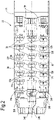
- a cabin 14 may include a seating arrangement 10 of a plurality of seating units 12A, and a plurality of seating units 12B.
- each seating unit 12A, 12B comprises a seat back 16, a seat pan 18, and a leg rest 20, which are configured to convert from an upright or reclined chair position to a substantially horizontal position, also commonly referred to as a bed position, as shown in Figures 7-8 .
- the angle of the bed position may be completely horizontal or may have a slightly angled position, in which the bed may be angled 2 degrees - 8 degrees when in flight relative to a completely 180 degree horizontal position when in flight.
- each seating unit 12A, 12B in the bed position may be configured to be positioned proximate a foot well 22A, 22B.
- Each foot well 22A, 22B is positioned in front of the corresponding seating unit 12A, 12B.
- the combined seating unit 12A, 12B in the bed position and the associated foot wells 22A, 22B provide a comfortable sleeping length for a passenger to lie down in a horizontal position.
- each bed position comprises a head end 34 and a foot end 36.
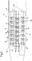
- the seating units 12A are longitudinally arranged in at least one column 24A, and the seating units 12B are longitudinally arranged in at least one column 24B.
- the columns 24A, 24B are positioned adjacent one another so that the seating units 12A, 12B in each column 24A, 24B are longitudinally aligned and positioned adjacent one another to form two-seat units 26, each two-seat unit 26 comprising one seating unit 12A from column 24A and one seating unit 12B from column 24B.
- the seating units 12A may form a longitudinal axis LA, and the seating units 12B may form a longitudinal axis LB.
- LA forms an angle a with a center axis C of the overall two-seat unit 26 (wherein the center axis C may be positioned parallel to the center axis C' of the cabin 14), and LB forms an angle b with a center axis C of the overall two-seat unit 26.
- angles a and b may range from 5 degrees to 15 degrees.
- angles a and b may be equal in magnitude but opposite in direction relative to the center axis C. The angles a and b are shallow enough relative to the center axis C to be considered forward facing.
- the seating units 12A, 12B are angled with respect to each other so that a distance between the head ends 34 is less than a distance between the foot ends 36.
- the passengers' feet are either angled toward an aisle 28 (for the columns 24B that are positioned adjacent an aisle 28) or toward an exterior wall 30 of the cabin 14 (for the columns 24A that are positioned adjacent the exterior wall 30).
- this angled arrangement for each two-seat unit 26 is referred to as a "paired herringbone" pattern.
- the shape of the wall 30 limits the amount of height available for upright sitting and head room.
- the seating units 12A By angling the seating units 12A so that the foot ends 36 are positioned in the concave space of the exterior wall 30 and limiting the height of at least a lateral-most portion 38 of each foot end 36 to fit within the dimensions of the concave space, the bed positions are arranged so that the foot ends 36 (which do not require the additional height) are positioned in the concave space, thus allowing the concave space to be more efficiently utilized, as best illustrated in Figure 7 .
- the space typically needed in the aisle at or above a delineating height is greater than the amount of space needed in the aisle below the delineating height (lower region).
- 63.5 cm (25 inches) is the delineating height between the narrower lower region of the aisle 28 and the wider upper region of the aisle 28.
- the narrower lower region of the aisle 28 is defined under current aircraft regulations as being the area of the aisle below 63.5 cm (25 inches)
- the wider upper region of the aisle 28 is defined under current aircraft regulations as being the area of the aisle at or above 63.5 cm (25 inches).
- the setpoint for the delineating height may be increased or decreased as needed or desired in future regulations, and the current design may be adjusted to conform to those changes in the delineating height setpoint.
- current aircraft regulations also govern the minimum widths of the narrower lower region of the aisle 28 and the wider upper region of the aisle 28.
- current regulations require a minimum aisle width of 38.1 cm (15 inches) for the narrower lower region, and require a minimum aisle width of 53.3 cm (21 inches) for the wider upper region.
- the setpoint for one or both minimum widths may be increased or decreased as needed or desired in future regulations, and the current design may be adjusted to conform to those changes in the minimum widths.
- the choice for the vertical setpoint of the delineating height is primarily chosen based on the fact that an average person's upper torso is wider than his or her lower torso, as best illustrated in Figure 7 .
- the bed positions can be arranged so that the foot ends 36 (which do not require the additional height) are positioned in the narrower lower portion of the aisle 28 that requires less width for passenger comfort.
- the surface upon which the person's feet rest inside the foot well 22B may be as much as 30.48-33.02 cm (12-13 inches) below the delineating height to allow for a height of the person's feet inside the foot well 22B and to maintain the upper surface of the foot well 22B below the delineating height, as shown in Figure 7 .
- the aisle 28 may have a narrower lower region below the delineating height that is only as wide as the minimum required width (which under the current regulations is 38.1 cm (15 inches), but may be larger or smaller depending on changes in the current regulations), while having a wider upper region at or above the delineating height (which under the current regulations is 53.3 cm (21 inches), but may be larger or smaller depending on changes in the current regulations).
- the difference in widths between the wider upper region and the narrower lower region is achieved by the lateral dimension of the height-limited portion 38 of each foot end 36.
- the lateral dimension of the height-limited portion 38 of each foot end 36 may range from approximately 2.54 cm (1 inch) to approximately 12.7 cm (5 inches).
- the height-limited portion 38 of the foot ends 36 may comprise a lateral portion of each foot well 22B, as best illustrated in Figure 11 .
- a privacy shell 40 around each seating unit 12B is recessed from a lateral edge of the foot well 22B by a distance that corresponds to the lateral dimension of the height-limited portion 38.
- the dimensions of the foot ends 36 may be the same for both seating units 12A, 12B, regardless of whether the foot end 36 is positioned adjacent the aisle 28 or in the concave space of the exterior wall 30. In other embodiments, there may be a desire to alter the dimensions of the foot end 36 adjacent the concave space of the exterior wall 30 so that the foot end 36 is able to extend above the delineating height, particularly in cases where the concave space may have a taller vertical dimension and thus allow for potential staggering or additional overlap of the seating units 12A, 12B in the bed positions if such additional compacting is desired.
- the arrangement 10 does not need to stagger the seating units 12A, 12B or overlap any portion of the seating units 12A, 12B. As a result, every bed position may be positioned at substantially the same height so that the passengers do not have to experience an overlapping bed arrangement, which tends to reduce the sense of privacy and comfort.
- an arrangement may include three sets of columns wherein one pair of columns 24A, 24B is positioned between the exterior wall 30 and the aisle 28, a second pair of columns 24B, 24A is positioned between the aisle 28 and a second aisle 28, and a third pair of columns 24B, 24B is positioned between the second aisle 28 and the opposing exterior wall 30.
- This arrangement 10 may also be referred to as a six abreast arrangement or a 2-2-2 arrangement.
- Such an arrangement may be used in wide body (two aisle) aircraft, such as Boeing 777X, 777 ( Figures 4 , 6 ), 787 ( Figure 2 ), 767, and 747 aircraft; and Airbus 380, 350 ( Figure 3 ), 340, and 330 ( Figure 1 ) aircraft.
- the seating units between the two aisles 28 may comprise a single column of seating units.
- This arrangement 10 may also be referred to as a five abreast arrangement or a 2-1-2 arrangement.
- Such an arrangement may be used in wide body (two aisle) aircraft, such as Boeing 777X, 777, 787, 767, and 747 aircraft; and Airbus 380, 350, 340, and 330 aircraft.
- an arrangement may include two sets of columns 24A, 24B, wherein one pair of columns 24A, 24B is positioned between the exterior wall 30 and the aisle 28, and a second pair of columns 24B, 24A is positioned between the aisle 28 and the opposing exterior wall 30.
- This arrangement 10 may also be referred to as a four abreast arrangement or a 2-2 arrangement.
- Such an arrangement may be used in narrow body (single aisle) aircraft, such as Boeing 737 aircraft ( Figure 5 ), Airbus 320 aircraft, and Bombadier CRJ aircraft.
- an arrangement may include one set of columns 24A, 24B, wherein one pair of columns 24A, 24B is positioned between the exterior wall 30 and the aisle 28, and a single column is positioned between the aisle 28 and the opposing exterior wall 30.
- This arrangement 10 may also be referred to as a three abreast arrangement or a 2-1 arrangement.
- Such an arrangement may also be used in narrow body (single aisle) aircraft, such as Boeing 737 aircraft ( Figure 5 ), Airbus 320 aircraft, and Bombadier CRJ aircraft.
- the arrangement 10 is able allow for a six abreast configuration on wide body aircraft, whereas the conventional maximum arrangement has been a four abreast configuration (two seats between two aisles and one seat between each aisle and one of the exterior walls).
- the laterally adjacent seating units may be integrally formed or connected as a double, triple, quad, or other suitably-sized seat unit.
Claims (15)
- Agencement de sièges pour les cabines de véhicules comprenant :une allée (28) et une paroi extérieure (30)au moins un ensemble de colonnes comprenant une colonne d'allée (24B) d'unités de siège (12B) positionnée de manière adjacente à une colonne de paroi (24A) d'unités de siège (12A), dans lequel la colonne d'allée (24B) est positionnée de manière adjacente à l'allée (28), et la colonne de paroi (24A) est positionnée de manière adjacente à la paroi extérieure (30) ;dans lequel chaque unité de siège (12A, 12B) comprend un dossier de siège (16), une assise de siège (18) et un repose-jambes (20) qui sont conçus pour passer d'une position de siège relevée ou inclinée à une position de lit ayant une extrémité de tête (34) et une extrémité de pieds (36) ;dans lequel les unités de siège dans les colonnes (24A, 24B) sont alignées longitudinalement et positionnées de manière adjacente les unes par rapport aux autres pour former des unités à deux sièges, chaque unité à deux sièges comprenant une unité de siège de la colonne d'allée (24B) et une unité de siège de la colonne de paroi (24A), qui forment un angle entre elles de sorte qu'une distance entre les extrémités de tête (34) est inférieure à une distance entre les extrémités de pieds (36) ;dans lequel une partie limitée en hauteur (38) de l'extrémité de pieds (36) pour une unité de siège (12B) de la colonne d'allée (24B) est limitée en hauteur par une hauteur de délimitation qui sépare une partie inférieure de l'allée (28) d'une partie supérieure de l'allée (28) de sorte que la partie inférieure de l'allée (28) en dessous de la hauteur de délimitation est plus étroite que la partie supérieure de l'allée (28) au niveau ou au-dessus de la hauteur de délimitation ;caractérisé en ce que :l'unité de siège (12A) de la colonne de paroi (24A) d'unités de siège forme un angle avec la paroi extérieure (30) pour positionner l'extrémité de pieds (36) dans une partie concave de la paroi extérieure (30) ;le repose-jambes (20) d'une unité de siège (12B) de la colonne d'allée (24B), lorsqu'il est en position de lit, est positionné à proximité d'un espace pour les pieds (22B) positionné devant l'unité de siège (12B) correspondante dans une unité de siège (12B) située immédiatement à l'avant ; et la partie limitée en hauteur (38) de l'extrémité de pieds (34) de l'unité de siège (12B) comprend une partie latérale de l'espace pour les pieds (22B).
- Agencement de sièges selon la revendication 1, dans lequel chaque unité de siège (12A, 12B) comprend un axe longitudinal qui forme un angle avec un axe central de l'unité à deux sièges.
- Agencement de sièges selon la revendication 2, dans lequel chaque angle a une amplitude de 5 degrés à 15 degrés.
- Agencement de sièges selon la revendication 3, dans lequel l'angle de chaque unité de siège (12B) dans la colonne d'allée (24B) est égal en amplitude et opposé en direction à l'angle de chaque unité de siège dans la colonne de paroi (24A).
- Agencement de sièges selon l'une quelconque des revendications précédentes, dans lequel la largeur de l'allée (28) inférieure à la hauteur de délimitation est la largeur minimale requise d'une allée d'avion inférieure à la hauteur de délimitation.
- Agencement de sièges selon la revendication 5, dans lequel la largeur de l'allée (28) inférieure à la hauteur de délimitation est de 38,1 cm (15 pouces).
- Agencement de sièges selon l'une quelconque des revendications précédentes, dans lequel la largeur de l'allée (28) égale ou supérieure à la hauteur de délimitation est la largeur minimale requise d'une allée d'avion égale ou supérieure à la hauteur de délimitation.
- Agencement de sièges selon la revendication 7, dans lequel la largeur de l'allée (28) égale ou supérieure à la hauteur de délimitation est de 53,3 cm (21 pouces).
- Agencement de sièges selon l'une quelconque des revendications précédentes, dans lequel la hauteur de délimitation est de 63,5 cm (25 pouces).
- Agencement de sièges selon l'une quelconque des revendications précédentes, dans lequel une dimension latérale de la partie limitée en hauteur de chaque espace pour les pieds (22B) est d'environ 2,54 cm (1 pouce) à environ 12,7 cm (5 pouces).
- Agencement de sièges selon l'une quelconque des revendications précédentes, dans lequel les positions de lit des unités de siège (12A, 12B) sont toutes agencées sensiblement à la même hauteur.
- Agencement de sièges selon l'une quelconque des revendications précédentes, comprenant en outre un deuxième ensemble de colonnes (24A, 24B) comprenant une colonne d'allée (24B) d'unités de siège (12B) positionnée de manière adjacente à une colonne de paroi (24A) d'unités de siège (12A), dans lequel la colonne de paroi est positionnée de manière adjacente à une seconde paroi extérieure.
- Agencement de sièges selon la revendication 12, comprenant en outre un troisième ensemble de colonnes positionné entre l'allée (28) et une seconde allée (28), dans lequel le troisième ensemble de colonnes comprend une première colonne d'allée (24B) adjacente à la première allée (28) et une seconde colonne d'allée (24B) adjacente à la seconde allée (28) ;
dans lequel les unités de siège dans les colonnes (24B) sont alignées longitudinalement et positionnées de manière adjacente les unes par rapport aux autres pour former des unités à deux sièges, chaque unité à deux sièges comprenant une unité de siège (12B) de la colonne d'allée (24B) et une unité de siège (12B) de la seconde colonne d'allée (24B), qui forment un angle entre elles de sorte qu'une distance entre les extrémités de tête (34) est inférieure à une distance entre les extrémités de pieds (36) ; - Agencement de sièges selon l'une quelconque des revendications précédentes, comprenant des unités de siège (12B) qui comprennent ;un espace pour les pieds (22B), destiné à être positionné à proximité du repose-jambes (20) d'une unité de siège située immédiatement à l'arrière ;dans lequel la hauteur d'une partie de l'espace pour les pieds (22B) est limitée par une hauteur de délimitation de l'allée ; etune coque d'intimité (40) autour de l'unité de siège (12B), dans lequel la coque d'intimité (40) est en retrait d'un bord latéral de l'espace pour les pieds (22B) selon une distance qui correspond à une dimension latérale de la partie limitée en hauteur (38), de sorte que la largeur de l'allée (28) supérieure à la hauteur de délimitation de l'allée est augmentée de la distance de retrait de la coque d'intimité (40).
- Aéronef comprenant l'agencement de sièges selon l'une quelconque des revendications 1 à 14 ou l'unité de siège selon la revendication 15.
Applications Claiming Priority (2)
| Application Number | Priority Date | Filing Date | Title |
|---|---|---|---|
| US201462060874P | 2014-10-07 | 2014-10-07 | |
| PCT/US2015/054568 WO2016057725A1 (fr) | 2014-10-07 | 2015-10-07 | Disposition en arêtes de poisson en paire de sièges de première classe à haute densité |
Publications (2)
| Publication Number | Publication Date |
|---|---|
| EP3204295A1 EP3204295A1 (fr) | 2017-08-16 |
| EP3204295B1 true EP3204295B1 (fr) | 2022-10-05 |
Family
ID=54337920
Family Applications (1)
| Application Number | Title | Priority Date | Filing Date |
|---|---|---|---|
| EP15784242.8A Active EP3204295B1 (fr) | 2014-10-07 | 2015-10-07 | Disposition en arêtes de poisson en paire de sièges de première classe à haute densité |
Country Status (3)
| Country | Link |
|---|---|
| US (1) | US11260975B2 (fr) |
| EP (1) | EP3204295B1 (fr) |
| WO (1) | WO2016057725A1 (fr) |
Cited By (1)
| Publication number | Priority date | Publication date | Assignee | Title |
|---|---|---|---|---|
| US20210061468A1 (en) * | 2019-08-26 | 2021-03-04 | Dassault Aviation | Aircraft cabin, extending into a fuselage along an aircraft axis and associated business jet |
Families Citing this family (9)
| Publication number | Priority date | Publication date | Assignee | Title |
|---|---|---|---|---|
| US11034452B2 (en) * | 2018-10-29 | 2021-06-15 | Safran Cabin Inc. | Aircraft with staggered seating arrangement |
| US10661879B2 (en) * | 2018-10-29 | 2020-05-26 | Safran Cabin Inc. | Aircraft with selective cargo area access |
| WO2020091886A1 (fr) * | 2018-10-29 | 2020-05-07 | Safran Cabin Inc. | Aéronef à configuration d'assise en angle |
| US10919631B2 (en) * | 2018-10-29 | 2021-02-16 | Safran Cabin Inc. | Aircraft with multiple doors and multiple zones |
| US11124300B2 (en) | 2018-11-15 | 2021-09-21 | B/E Aerospace, Inc. | Business class all aisle access passenger seat configuration |
| DE102019204334B4 (de) * | 2019-03-28 | 2023-05-04 | Adient Aerospace, Llc | Sitzanordnung und Luftfahrzeug mit mehreren Sitzanordnungen |
| DE102020105072A1 (de) * | 2020-02-26 | 2021-08-26 | Recaro Aircraft Seating Gmbh & Co. Kg | Flugzeugsitzanordnung |
| DE102020108436A1 (de) * | 2020-03-26 | 2021-09-30 | Recaro Aircraft Seating Gmbh & Co. Kg | Flugzeugsitzanordnung |
| FR3134546A1 (fr) | 2022-04-13 | 2023-10-20 | Airbus Atlantic Sas | Arrangement de sièges pour cabine d’avion monocouloir |
Citations (4)
| Publication number | Priority date | Publication date | Assignee | Title |
|---|---|---|---|---|
| WO2013063599A1 (fr) * | 2011-10-28 | 2013-05-02 | C&D Zodiac, Inc. | Configuration de sièges d'aéronef |
| WO2014006607A2 (fr) * | 2012-07-06 | 2014-01-09 | Zodiac Seats France | Agencement de cabine classe affaires haut de gamme |
| WO2014049362A1 (fr) * | 2012-09-27 | 2014-04-03 | Acumen Design Associates Ltd | Agencement de sièges passagers d'avion |
| GB2510765A (en) * | 2014-01-07 | 2014-08-13 | British Airways Plc | Aircraft passenger seating arrangement |
Family Cites Families (13)
| Publication number | Priority date | Publication date | Assignee | Title |
|---|---|---|---|---|
| CA2625107C (fr) * | 2001-08-09 | 2009-11-03 | Virgin Atlantic Airways Limited | Systeme de sieges et unite d'accueil de passagers pour vehicule |
| FR2924683A1 (fr) * | 2007-12-06 | 2009-06-12 | Airbus Sas | Amenagement optimise d'une cabine d'aeronef |
| GB0816742D0 (en) | 2008-09-12 | 2008-10-22 | American Airlines | Array of aircraft seats |
| US8196864B2 (en) * | 2008-09-05 | 2012-06-12 | Weber Aircraft Llc | Seating arrangements particularly for passenger aircraft |
| GB0903744D0 (en) | 2009-03-04 | 2009-04-15 | Virgin Atlantic Airways Ltd | A seating insallation for a passenger vehicle |
| FR2943286B3 (fr) * | 2009-03-23 | 2011-02-25 | Air New Zealand Ltd | Ameliorations de ou concernant des sieges de passagers dans un vehicule |
| FR2953168B1 (fr) | 2009-12-02 | 2012-01-06 | Eads Sogerma | Siege convertible en couchette |
| USD649793S1 (en) * | 2009-12-10 | 2011-12-06 | Air New Zealand Limited | Aircraft seat |
| FR2975952B1 (fr) | 2011-06-01 | 2013-07-19 | Eads Sogerma | Siege convertible en couchette |
| US10144513B2 (en) | 2012-12-06 | 2018-12-04 | Zodiac Seats France | High density full flat business class seat cabin |
| FR3003540B1 (fr) * | 2013-03-25 | 2015-05-29 | Eads Sogerma | Agencement de sieges convertibles en couchettes |
| GB201306432D0 (en) * | 2013-04-09 | 2013-05-22 | James Park Associates Ltd | Personal units |
| ITUB20153008A1 (it) * | 2015-08-07 | 2017-02-07 | Optimares S P A | Assieme di poltrone per aereo. |
-
2015
- 2015-10-07 EP EP15784242.8A patent/EP3204295B1/fr active Active
- 2015-10-07 US US15/517,657 patent/US11260975B2/en active Active
- 2015-10-07 WO PCT/US2015/054568 patent/WO2016057725A1/fr active Application Filing
Patent Citations (4)
| Publication number | Priority date | Publication date | Assignee | Title |
|---|---|---|---|---|
| WO2013063599A1 (fr) * | 2011-10-28 | 2013-05-02 | C&D Zodiac, Inc. | Configuration de sièges d'aéronef |
| WO2014006607A2 (fr) * | 2012-07-06 | 2014-01-09 | Zodiac Seats France | Agencement de cabine classe affaires haut de gamme |
| WO2014049362A1 (fr) * | 2012-09-27 | 2014-04-03 | Acumen Design Associates Ltd | Agencement de sièges passagers d'avion |
| GB2510765A (en) * | 2014-01-07 | 2014-08-13 | British Airways Plc | Aircraft passenger seating arrangement |
Cited By (1)
| Publication number | Priority date | Publication date | Assignee | Title |
|---|---|---|---|---|
| US20210061468A1 (en) * | 2019-08-26 | 2021-03-04 | Dassault Aviation | Aircraft cabin, extending into a fuselage along an aircraft axis and associated business jet |
Also Published As
| Publication number | Publication date |
|---|---|
| WO2016057725A1 (fr) | 2016-04-14 |
| US11260975B2 (en) | 2022-03-01 |
| US20170297719A1 (en) | 2017-10-19 |
| EP3204295A1 (fr) | 2017-08-16 |
Similar Documents
| Publication | Publication Date | Title |
|---|---|---|
| EP3204295B1 (fr) | Disposition en arêtes de poisson en paire de sièges de première classe à haute densité | |
| EP2828163B1 (fr) | Cabine de siège de classe affaire entièrement plat à densité élevée | |
| US10569884B2 (en) | Aircraft passenger seat with enhanced lie flat position spacing | |
| EP3077287B1 (fr) | Agencement de sièges de classe affaires haut de gamme | |
| EP3374266B1 (fr) | Agencement de siège d'aéronef présentant espacement de position à disposition plate amélioré | |
| EP2948372B1 (fr) | Extension du lit | |
| EP3280641B1 (fr) | Sièges à appui universels | |
| JP4685473B2 (ja) | 航空機の客室用座席の配列構造 | |
| EP2825460B1 (fr) | Agencement de siéges d'aéronef à haute densité | |
| US9868531B2 (en) | Passenger seat arrangement for a vehicle | |
| JP4673087B2 (ja) | 航空機の客室用座席の配列構造 | |
| EP3549865B1 (fr) | Unité de siège passager d'aéronef et agencement de sièges pour passager | |
| WO2020188279A1 (fr) | Ensemble d'unités formant siège de passager d'aéronef | |
| GB2565674B (en) | High density aircraft seat arrangement |
Legal Events
| Date | Code | Title | Description |
|---|---|---|---|
| STAA | Information on the status of an ep patent application or granted ep patent |
Free format text: STATUS: THE INTERNATIONAL PUBLICATION HAS BEEN MADE |
|
| PUAI | Public reference made under article 153(3) epc to a published international application that has entered the european phase |
Free format text: ORIGINAL CODE: 0009012 |
|
| STAA | Information on the status of an ep patent application or granted ep patent |
Free format text: STATUS: REQUEST FOR EXAMINATION WAS MADE |
|
| 17P | Request for examination filed |
Effective date: 20170504 |
|
| AK | Designated contracting states |
Kind code of ref document: A1 Designated state(s): AL AT BE BG CH CY CZ DE DK EE ES FI FR GB GR HR HU IE IS IT LI LT LU LV MC MK MT NL NO PL PT RO RS SE SI SK SM TR |
|
| AX | Request for extension of the european patent |
Extension state: BA ME |
|
| RIN1 | Information on inventor provided before grant (corrected) |
Inventor name: LORSIGNOL, FELIX J. Inventor name: CLEARY, MATTHEW |
|
| DAV | Request for validation of the european patent (deleted) | ||
| DAX | Request for extension of the european patent (deleted) | ||
| RAP1 | Party data changed (applicant data changed or rights of an application transferred) |
Owner name: SAFRAN SEATS GB LIMITED |
|
| STAA | Information on the status of an ep patent application or granted ep patent |
Free format text: STATUS: EXAMINATION IS IN PROGRESS |
|
| 17Q | First examination report despatched |
Effective date: 20200709 |
|
| STAA | Information on the status of an ep patent application or granted ep patent |
Free format text: STATUS: EXAMINATION IS IN PROGRESS |
|
| GRAP | Despatch of communication of intention to grant a patent |
Free format text: ORIGINAL CODE: EPIDOSNIGR1 |
|
| STAA | Information on the status of an ep patent application or granted ep patent |
Free format text: STATUS: GRANT OF PATENT IS INTENDED |
|
| INTG | Intention to grant announced |
Effective date: 20220107 |
|
| GRAJ | Information related to disapproval of communication of intention to grant by the applicant or resumption of examination proceedings by the epo deleted |
Free format text: ORIGINAL CODE: EPIDOSDIGR1 |
|
| STAA | Information on the status of an ep patent application or granted ep patent |
Free format text: STATUS: EXAMINATION IS IN PROGRESS |
|
| INTC | Intention to grant announced (deleted) | ||
| GRAP | Despatch of communication of intention to grant a patent |
Free format text: ORIGINAL CODE: EPIDOSNIGR1 |
|
| STAA | Information on the status of an ep patent application or granted ep patent |
Free format text: STATUS: GRANT OF PATENT IS INTENDED |
|
| INTG | Intention to grant announced |
Effective date: 20220718 |
|
| GRAS | Grant fee paid |
Free format text: ORIGINAL CODE: EPIDOSNIGR3 |
|
| GRAA | (expected) grant |
Free format text: ORIGINAL CODE: 0009210 |
|
| STAA | Information on the status of an ep patent application or granted ep patent |
Free format text: STATUS: THE PATENT HAS BEEN GRANTED |
|
| AK | Designated contracting states |
Kind code of ref document: B1 Designated state(s): AL AT BE BG CH CY CZ DE DK EE ES FI FR GB GR HR HU IE IS IT LI LT LU LV MC MK MT NL NO PL PT RO RS SE SI SK SM TR |
|
| REG | Reference to a national code |
Ref country code: GB Ref legal event code: FG4D |
|
| REG | Reference to a national code |
Ref country code: CH Ref legal event code: EP |
|
| REG | Reference to a national code |
Ref country code: AT Ref legal event code: REF Ref document number: 1522618 Country of ref document: AT Kind code of ref document: T Effective date: 20221015 |
|
| REG | Reference to a national code |
Ref country code: IE Ref legal event code: FG4D |
|
| REG | Reference to a national code |
Ref country code: DE Ref legal event code: R096 Ref document number: 602015081070 Country of ref document: DE |
|
| REG | Reference to a national code |
Ref country code: LT Ref legal event code: MG9D |
|
| REG | Reference to a national code |
Ref country code: NL Ref legal event code: MP Effective date: 20221005 |
|
| REG | Reference to a national code |
Ref country code: AT Ref legal event code: MK05 Ref document number: 1522618 Country of ref document: AT Kind code of ref document: T Effective date: 20221005 |
|
| PG25 | Lapsed in a contracting state [announced via postgrant information from national office to epo] |
Ref country code: NL Free format text: LAPSE BECAUSE OF FAILURE TO SUBMIT A TRANSLATION OF THE DESCRIPTION OR TO PAY THE FEE WITHIN THE PRESCRIBED TIME-LIMIT Effective date: 20221005 |
|
| PG25 | Lapsed in a contracting state [announced via postgrant information from national office to epo] |
Ref country code: SE Free format text: LAPSE BECAUSE OF FAILURE TO SUBMIT A TRANSLATION OF THE DESCRIPTION OR TO PAY THE FEE WITHIN THE PRESCRIBED TIME-LIMIT Effective date: 20221005 Ref country code: PT Free format text: LAPSE BECAUSE OF FAILURE TO SUBMIT A TRANSLATION OF THE DESCRIPTION OR TO PAY THE FEE WITHIN THE PRESCRIBED TIME-LIMIT Effective date: 20230206 Ref country code: NO Free format text: LAPSE BECAUSE OF FAILURE TO SUBMIT A TRANSLATION OF THE DESCRIPTION OR TO PAY THE FEE WITHIN THE PRESCRIBED TIME-LIMIT Effective date: 20230105 Ref country code: LT Free format text: LAPSE BECAUSE OF FAILURE TO SUBMIT A TRANSLATION OF THE DESCRIPTION OR TO PAY THE FEE WITHIN THE PRESCRIBED TIME-LIMIT Effective date: 20221005 Ref country code: FI Free format text: LAPSE BECAUSE OF FAILURE TO SUBMIT A TRANSLATION OF THE DESCRIPTION OR TO PAY THE FEE WITHIN THE PRESCRIBED TIME-LIMIT Effective date: 20221005 Ref country code: ES Free format text: LAPSE BECAUSE OF FAILURE TO SUBMIT A TRANSLATION OF THE DESCRIPTION OR TO PAY THE FEE WITHIN THE PRESCRIBED TIME-LIMIT Effective date: 20221005 Ref country code: AT Free format text: LAPSE BECAUSE OF FAILURE TO SUBMIT A TRANSLATION OF THE DESCRIPTION OR TO PAY THE FEE WITHIN THE PRESCRIBED TIME-LIMIT Effective date: 20221005 |
|
| PG25 | Lapsed in a contracting state [announced via postgrant information from national office to epo] |
Ref country code: RS Free format text: LAPSE BECAUSE OF FAILURE TO SUBMIT A TRANSLATION OF THE DESCRIPTION OR TO PAY THE FEE WITHIN THE PRESCRIBED TIME-LIMIT Effective date: 20221005 Ref country code: PL Free format text: LAPSE BECAUSE OF FAILURE TO SUBMIT A TRANSLATION OF THE DESCRIPTION OR TO PAY THE FEE WITHIN THE PRESCRIBED TIME-LIMIT Effective date: 20221005 Ref country code: LV Free format text: LAPSE BECAUSE OF FAILURE TO SUBMIT A TRANSLATION OF THE DESCRIPTION OR TO PAY THE FEE WITHIN THE PRESCRIBED TIME-LIMIT Effective date: 20221005 Ref country code: IS Free format text: LAPSE BECAUSE OF FAILURE TO SUBMIT A TRANSLATION OF THE DESCRIPTION OR TO PAY THE FEE WITHIN THE PRESCRIBED TIME-LIMIT Effective date: 20230205 Ref country code: HR Free format text: LAPSE BECAUSE OF FAILURE TO SUBMIT A TRANSLATION OF THE DESCRIPTION OR TO PAY THE FEE WITHIN THE PRESCRIBED TIME-LIMIT Effective date: 20221005 Ref country code: GR Free format text: LAPSE BECAUSE OF FAILURE TO SUBMIT A TRANSLATION OF THE DESCRIPTION OR TO PAY THE FEE WITHIN THE PRESCRIBED TIME-LIMIT Effective date: 20230106 |
|
| REG | Reference to a national code |
Ref country code: CH Ref legal event code: PL |
|
| REG | Reference to a national code |
Ref country code: BE Ref legal event code: MM Effective date: 20221031 |
|
| PG25 | Lapsed in a contracting state [announced via postgrant information from national office to epo] |
Ref country code: LU Free format text: LAPSE BECAUSE OF NON-PAYMENT OF DUE FEES Effective date: 20221007 |
|
| REG | Reference to a national code |
Ref country code: DE Ref legal event code: R097 Ref document number: 602015081070 Country of ref document: DE |
|
| PG25 | Lapsed in a contracting state [announced via postgrant information from national office to epo] |
Ref country code: SM Free format text: LAPSE BECAUSE OF FAILURE TO SUBMIT A TRANSLATION OF THE DESCRIPTION OR TO PAY THE FEE WITHIN THE PRESCRIBED TIME-LIMIT Effective date: 20221005 Ref country code: RO Free format text: LAPSE BECAUSE OF FAILURE TO SUBMIT A TRANSLATION OF THE DESCRIPTION OR TO PAY THE FEE WITHIN THE PRESCRIBED TIME-LIMIT Effective date: 20221005 Ref country code: MC Free format text: LAPSE BECAUSE OF FAILURE TO SUBMIT A TRANSLATION OF THE DESCRIPTION OR TO PAY THE FEE WITHIN THE PRESCRIBED TIME-LIMIT Effective date: 20221005 Ref country code: LI Free format text: LAPSE BECAUSE OF NON-PAYMENT OF DUE FEES Effective date: 20221031 Ref country code: EE Free format text: LAPSE BECAUSE OF FAILURE TO SUBMIT A TRANSLATION OF THE DESCRIPTION OR TO PAY THE FEE WITHIN THE PRESCRIBED TIME-LIMIT Effective date: 20221005 Ref country code: DK Free format text: LAPSE BECAUSE OF FAILURE TO SUBMIT A TRANSLATION OF THE DESCRIPTION OR TO PAY THE FEE WITHIN THE PRESCRIBED TIME-LIMIT Effective date: 20221005 Ref country code: CZ Free format text: LAPSE BECAUSE OF FAILURE TO SUBMIT A TRANSLATION OF THE DESCRIPTION OR TO PAY THE FEE WITHIN THE PRESCRIBED TIME-LIMIT Effective date: 20221005 Ref country code: CH Free format text: LAPSE BECAUSE OF NON-PAYMENT OF DUE FEES Effective date: 20221031 |
|
| PLBE | No opposition filed within time limit |
Free format text: ORIGINAL CODE: 0009261 |
|
| STAA | Information on the status of an ep patent application or granted ep patent |
Free format text: STATUS: NO OPPOSITION FILED WITHIN TIME LIMIT |
|
| PG25 | Lapsed in a contracting state [announced via postgrant information from national office to epo] |
Ref country code: SK Free format text: LAPSE BECAUSE OF FAILURE TO SUBMIT A TRANSLATION OF THE DESCRIPTION OR TO PAY THE FEE WITHIN THE PRESCRIBED TIME-LIMIT Effective date: 20221005 Ref country code: AL Free format text: LAPSE BECAUSE OF FAILURE TO SUBMIT A TRANSLATION OF THE DESCRIPTION OR TO PAY THE FEE WITHIN THE PRESCRIBED TIME-LIMIT Effective date: 20221005 |
|
| 26N | No opposition filed |
Effective date: 20230706 |
|
| PG25 | Lapsed in a contracting state [announced via postgrant information from national office to epo] |
Ref country code: BE Free format text: LAPSE BECAUSE OF NON-PAYMENT OF DUE FEES Effective date: 20221031 |
|
| PG25 | Lapsed in a contracting state [announced via postgrant information from national office to epo] |
Ref country code: IE Free format text: LAPSE BECAUSE OF NON-PAYMENT OF DUE FEES Effective date: 20221007 |
|
| PGFP | Annual fee paid to national office [announced via postgrant information from national office to epo] |
Ref country code: GB Payment date: 20230920 Year of fee payment: 9 |
|
| PG25 | Lapsed in a contracting state [announced via postgrant information from national office to epo] |
Ref country code: SI Free format text: LAPSE BECAUSE OF FAILURE TO SUBMIT A TRANSLATION OF THE DESCRIPTION OR TO PAY THE FEE WITHIN THE PRESCRIBED TIME-LIMIT Effective date: 20221005 |
|
| PGFP | Annual fee paid to national office [announced via postgrant information from national office to epo] |
Ref country code: FR Payment date: 20230920 Year of fee payment: 9 |
|
| PGFP | Annual fee paid to national office [announced via postgrant information from national office to epo] |
Ref country code: DE Payment date: 20230920 Year of fee payment: 9 |
|
| PG25 | Lapsed in a contracting state [announced via postgrant information from national office to epo] |
Ref country code: HU Free format text: LAPSE BECAUSE OF FAILURE TO SUBMIT A TRANSLATION OF THE DESCRIPTION OR TO PAY THE FEE WITHIN THE PRESCRIBED TIME-LIMIT; INVALID AB INITIO Effective date: 20151007 |
|
| PG25 | Lapsed in a contracting state [announced via postgrant information from national office to epo] |
Ref country code: CY Free format text: LAPSE BECAUSE OF FAILURE TO SUBMIT A TRANSLATION OF THE DESCRIPTION OR TO PAY THE FEE WITHIN THE PRESCRIBED TIME-LIMIT Effective date: 20221005 |