EP3203939B1 - Interkorporelles distanzstück - Google Patents
Interkorporelles distanzstück Download PDFInfo
- Publication number
- EP3203939B1 EP3203939B1 EP15849152.2A EP15849152A EP3203939B1 EP 3203939 B1 EP3203939 B1 EP 3203939B1 EP 15849152 A EP15849152 A EP 15849152A EP 3203939 B1 EP3203939 B1 EP 3203939B1
- Authority
- EP
- European Patent Office
- Prior art keywords
- spinal implant
- lower body
- ratchet
- upper body
- screw
- Prior art date
- Legal status (The legal status is an assumption and is not a legal conclusion. Google has not performed a legal analysis and makes no representation as to the accuracy of the status listed.)
- Active
Links
Images







Classifications
-
- A—HUMAN NECESSITIES
- A61—MEDICAL OR VETERINARY SCIENCE; HYGIENE
- A61F—FILTERS IMPLANTABLE INTO BLOOD VESSELS; PROSTHESES; DEVICES PROVIDING PATENCY TO, OR PREVENTING COLLAPSING OF, TUBULAR STRUCTURES OF THE BODY, e.g. STENTS; ORTHOPAEDIC, NURSING OR CONTRACEPTIVE DEVICES; FOMENTATION; TREATMENT OR PROTECTION OF EYES OR EARS; BANDAGES, DRESSINGS OR ABSORBENT PADS; FIRST-AID KITS
- A61F2/00—Filters implantable into blood vessels; Prostheses, i.e. artificial substitutes or replacements for parts of the body; Appliances for connecting them with the body; Devices providing patency to, or preventing collapsing of, tubular structures of the body, e.g. stents
- A61F2/02—Prostheses implantable into the body
- A61F2/30—Joints
- A61F2/44—Joints for the spine, e.g. vertebrae, spinal discs
- A61F2/442—Intervertebral or spinal discs, e.g. resilient
-
- A—HUMAN NECESSITIES
- A61—MEDICAL OR VETERINARY SCIENCE; HYGIENE
- A61F—FILTERS IMPLANTABLE INTO BLOOD VESSELS; PROSTHESES; DEVICES PROVIDING PATENCY TO, OR PREVENTING COLLAPSING OF, TUBULAR STRUCTURES OF THE BODY, e.g. STENTS; ORTHOPAEDIC, NURSING OR CONTRACEPTIVE DEVICES; FOMENTATION; TREATMENT OR PROTECTION OF EYES OR EARS; BANDAGES, DRESSINGS OR ABSORBENT PADS; FIRST-AID KITS
- A61F2/00—Filters implantable into blood vessels; Prostheses, i.e. artificial substitutes or replacements for parts of the body; Appliances for connecting them with the body; Devices providing patency to, or preventing collapsing of, tubular structures of the body, e.g. stents
- A61F2/02—Prostheses implantable into the body
- A61F2/30—Joints
- A61F2/30767—Special external or bone-contacting surface, e.g. coating for improving bone ingrowth
- A61F2/30771—Special external or bone-contacting surface, e.g. coating for improving bone ingrowth applied in original prostheses, e.g. holes or grooves
-
- A—HUMAN NECESSITIES
- A61—MEDICAL OR VETERINARY SCIENCE; HYGIENE
- A61F—FILTERS IMPLANTABLE INTO BLOOD VESSELS; PROSTHESES; DEVICES PROVIDING PATENCY TO, OR PREVENTING COLLAPSING OF, TUBULAR STRUCTURES OF THE BODY, e.g. STENTS; ORTHOPAEDIC, NURSING OR CONTRACEPTIVE DEVICES; FOMENTATION; TREATMENT OR PROTECTION OF EYES OR EARS; BANDAGES, DRESSINGS OR ABSORBENT PADS; FIRST-AID KITS
- A61F2/00—Filters implantable into blood vessels; Prostheses, i.e. artificial substitutes or replacements for parts of the body; Appliances for connecting them with the body; Devices providing patency to, or preventing collapsing of, tubular structures of the body, e.g. stents
- A61F2/02—Prostheses implantable into the body
- A61F2/30—Joints
- A61F2/44—Joints for the spine, e.g. vertebrae, spinal discs
- A61F2/4455—Joints for the spine, e.g. vertebrae, spinal discs for the fusion of spinal bodies, e.g. intervertebral fusion of adjacent spinal bodies, e.g. fusion cages
-
- A—HUMAN NECESSITIES
- A61—MEDICAL OR VETERINARY SCIENCE; HYGIENE
- A61F—FILTERS IMPLANTABLE INTO BLOOD VESSELS; PROSTHESES; DEVICES PROVIDING PATENCY TO, OR PREVENTING COLLAPSING OF, TUBULAR STRUCTURES OF THE BODY, e.g. STENTS; ORTHOPAEDIC, NURSING OR CONTRACEPTIVE DEVICES; FOMENTATION; TREATMENT OR PROTECTION OF EYES OR EARS; BANDAGES, DRESSINGS OR ABSORBENT PADS; FIRST-AID KITS
- A61F2/00—Filters implantable into blood vessels; Prostheses, i.e. artificial substitutes or replacements for parts of the body; Appliances for connecting them with the body; Devices providing patency to, or preventing collapsing of, tubular structures of the body, e.g. stents
- A61F2/02—Prostheses implantable into the body
- A61F2/30—Joints
- A61F2/46—Special tools for implanting artificial joints
- A61F2/4603—Special tools for implanting artificial joints for insertion or extraction of endoprosthetic joints or of accessories thereof
- A61F2/4611—Special tools for implanting artificial joints for insertion or extraction of endoprosthetic joints or of accessories thereof of spinal prostheses
-
- A—HUMAN NECESSITIES
- A61—MEDICAL OR VETERINARY SCIENCE; HYGIENE
- A61F—FILTERS IMPLANTABLE INTO BLOOD VESSELS; PROSTHESES; DEVICES PROVIDING PATENCY TO, OR PREVENTING COLLAPSING OF, TUBULAR STRUCTURES OF THE BODY, e.g. STENTS; ORTHOPAEDIC, NURSING OR CONTRACEPTIVE DEVICES; FOMENTATION; TREATMENT OR PROTECTION OF EYES OR EARS; BANDAGES, DRESSINGS OR ABSORBENT PADS; FIRST-AID KITS
- A61F2/00—Filters implantable into blood vessels; Prostheses, i.e. artificial substitutes or replacements for parts of the body; Appliances for connecting them with the body; Devices providing patency to, or preventing collapsing of, tubular structures of the body, e.g. stents
- A61F2/02—Prostheses implantable into the body
- A61F2/30—Joints
- A61F2002/30001—Additional features of subject-matter classified in A61F2/28, A61F2/30 and subgroups thereof
- A61F2002/30108—Shapes
- A61F2002/3011—Cross-sections or two-dimensional shapes
- A61F2002/30159—Concave polygonal shapes
- A61F2002/30172—T-shaped
-
- A—HUMAN NECESSITIES
- A61—MEDICAL OR VETERINARY SCIENCE; HYGIENE
- A61F—FILTERS IMPLANTABLE INTO BLOOD VESSELS; PROSTHESES; DEVICES PROVIDING PATENCY TO, OR PREVENTING COLLAPSING OF, TUBULAR STRUCTURES OF THE BODY, e.g. STENTS; ORTHOPAEDIC, NURSING OR CONTRACEPTIVE DEVICES; FOMENTATION; TREATMENT OR PROTECTION OF EYES OR EARS; BANDAGES, DRESSINGS OR ABSORBENT PADS; FIRST-AID KITS
- A61F2/00—Filters implantable into blood vessels; Prostheses, i.e. artificial substitutes or replacements for parts of the body; Appliances for connecting them with the body; Devices providing patency to, or preventing collapsing of, tubular structures of the body, e.g. stents
- A61F2/02—Prostheses implantable into the body
- A61F2/30—Joints
- A61F2002/30001—Additional features of subject-matter classified in A61F2/28, A61F2/30 and subgroups thereof
- A61F2002/30316—The prosthesis having different structural features at different locations within the same prosthesis; Connections between prosthetic parts; Special structural features of bone or joint prostheses not otherwise provided for
- A61F2002/30329—Connections or couplings between prosthetic parts, e.g. between modular parts; Connecting elements
- A61F2002/30383—Connections or couplings between prosthetic parts, e.g. between modular parts; Connecting elements made by laterally inserting a protrusion, e.g. a rib into a complementarily-shaped groove
-
- A—HUMAN NECESSITIES
- A61—MEDICAL OR VETERINARY SCIENCE; HYGIENE
- A61F—FILTERS IMPLANTABLE INTO BLOOD VESSELS; PROSTHESES; DEVICES PROVIDING PATENCY TO, OR PREVENTING COLLAPSING OF, TUBULAR STRUCTURES OF THE BODY, e.g. STENTS; ORTHOPAEDIC, NURSING OR CONTRACEPTIVE DEVICES; FOMENTATION; TREATMENT OR PROTECTION OF EYES OR EARS; BANDAGES, DRESSINGS OR ABSORBENT PADS; FIRST-AID KITS
- A61F2/00—Filters implantable into blood vessels; Prostheses, i.e. artificial substitutes or replacements for parts of the body; Appliances for connecting them with the body; Devices providing patency to, or preventing collapsing of, tubular structures of the body, e.g. stents
- A61F2/02—Prostheses implantable into the body
- A61F2/30—Joints
- A61F2002/30001—Additional features of subject-matter classified in A61F2/28, A61F2/30 and subgroups thereof
- A61F2002/30316—The prosthesis having different structural features at different locations within the same prosthesis; Connections between prosthetic parts; Special structural features of bone or joint prostheses not otherwise provided for
- A61F2002/30329—Connections or couplings between prosthetic parts, e.g. between modular parts; Connecting elements
- A61F2002/30383—Connections or couplings between prosthetic parts, e.g. between modular parts; Connecting elements made by laterally inserting a protrusion, e.g. a rib into a complementarily-shaped groove
- A61F2002/3039—Connections or couplings between prosthetic parts, e.g. between modular parts; Connecting elements made by laterally inserting a protrusion, e.g. a rib into a complementarily-shaped groove with possibility of relative movement of the rib within the groove
- A61F2002/30398—Sliding
-
- A—HUMAN NECESSITIES
- A61—MEDICAL OR VETERINARY SCIENCE; HYGIENE
- A61F—FILTERS IMPLANTABLE INTO BLOOD VESSELS; PROSTHESES; DEVICES PROVIDING PATENCY TO, OR PREVENTING COLLAPSING OF, TUBULAR STRUCTURES OF THE BODY, e.g. STENTS; ORTHOPAEDIC, NURSING OR CONTRACEPTIVE DEVICES; FOMENTATION; TREATMENT OR PROTECTION OF EYES OR EARS; BANDAGES, DRESSINGS OR ABSORBENT PADS; FIRST-AID KITS
- A61F2/00—Filters implantable into blood vessels; Prostheses, i.e. artificial substitutes or replacements for parts of the body; Appliances for connecting them with the body; Devices providing patency to, or preventing collapsing of, tubular structures of the body, e.g. stents
- A61F2/02—Prostheses implantable into the body
- A61F2/30—Joints
- A61F2002/30001—Additional features of subject-matter classified in A61F2/28, A61F2/30 and subgroups thereof
- A61F2002/30316—The prosthesis having different structural features at different locations within the same prosthesis; Connections between prosthetic parts; Special structural features of bone or joint prostheses not otherwise provided for
- A61F2002/30329—Connections or couplings between prosthetic parts, e.g. between modular parts; Connecting elements
- A61F2002/30405—Connections or couplings between prosthetic parts, e.g. between modular parts; Connecting elements made by screwing complementary threads machined on the parts themselves
-
- A—HUMAN NECESSITIES
- A61—MEDICAL OR VETERINARY SCIENCE; HYGIENE
- A61F—FILTERS IMPLANTABLE INTO BLOOD VESSELS; PROSTHESES; DEVICES PROVIDING PATENCY TO, OR PREVENTING COLLAPSING OF, TUBULAR STRUCTURES OF THE BODY, e.g. STENTS; ORTHOPAEDIC, NURSING OR CONTRACEPTIVE DEVICES; FOMENTATION; TREATMENT OR PROTECTION OF EYES OR EARS; BANDAGES, DRESSINGS OR ABSORBENT PADS; FIRST-AID KITS
- A61F2/00—Filters implantable into blood vessels; Prostheses, i.e. artificial substitutes or replacements for parts of the body; Appliances for connecting them with the body; Devices providing patency to, or preventing collapsing of, tubular structures of the body, e.g. stents
- A61F2/02—Prostheses implantable into the body
- A61F2/30—Joints
- A61F2002/30001—Additional features of subject-matter classified in A61F2/28, A61F2/30 and subgroups thereof
- A61F2002/30316—The prosthesis having different structural features at different locations within the same prosthesis; Connections between prosthetic parts; Special structural features of bone or joint prostheses not otherwise provided for
- A61F2002/30329—Connections or couplings between prosthetic parts, e.g. between modular parts; Connecting elements
- A61F2002/30471—Connections or couplings between prosthetic parts, e.g. between modular parts; Connecting elements connected by a hinged linkage mechanism, e.g. of the single-bar or multi-bar linkage type
-
- A—HUMAN NECESSITIES
- A61—MEDICAL OR VETERINARY SCIENCE; HYGIENE
- A61F—FILTERS IMPLANTABLE INTO BLOOD VESSELS; PROSTHESES; DEVICES PROVIDING PATENCY TO, OR PREVENTING COLLAPSING OF, TUBULAR STRUCTURES OF THE BODY, e.g. STENTS; ORTHOPAEDIC, NURSING OR CONTRACEPTIVE DEVICES; FOMENTATION; TREATMENT OR PROTECTION OF EYES OR EARS; BANDAGES, DRESSINGS OR ABSORBENT PADS; FIRST-AID KITS
- A61F2/00—Filters implantable into blood vessels; Prostheses, i.e. artificial substitutes or replacements for parts of the body; Appliances for connecting them with the body; Devices providing patency to, or preventing collapsing of, tubular structures of the body, e.g. stents
- A61F2/02—Prostheses implantable into the body
- A61F2/30—Joints
- A61F2002/30001—Additional features of subject-matter classified in A61F2/28, A61F2/30 and subgroups thereof
- A61F2002/30316—The prosthesis having different structural features at different locations within the same prosthesis; Connections between prosthetic parts; Special structural features of bone or joint prostheses not otherwise provided for
- A61F2002/30329—Connections or couplings between prosthetic parts, e.g. between modular parts; Connecting elements
- A61F2002/30476—Connections or couplings between prosthetic parts, e.g. between modular parts; Connecting elements locked by an additional locking mechanism
- A61F2002/30487—Circumferential cooperating grooves and beads on cooperating lateral surfaces of a mainly longitudinal connection
-
- A—HUMAN NECESSITIES
- A61—MEDICAL OR VETERINARY SCIENCE; HYGIENE
- A61F—FILTERS IMPLANTABLE INTO BLOOD VESSELS; PROSTHESES; DEVICES PROVIDING PATENCY TO, OR PREVENTING COLLAPSING OF, TUBULAR STRUCTURES OF THE BODY, e.g. STENTS; ORTHOPAEDIC, NURSING OR CONTRACEPTIVE DEVICES; FOMENTATION; TREATMENT OR PROTECTION OF EYES OR EARS; BANDAGES, DRESSINGS OR ABSORBENT PADS; FIRST-AID KITS
- A61F2/00—Filters implantable into blood vessels; Prostheses, i.e. artificial substitutes or replacements for parts of the body; Appliances for connecting them with the body; Devices providing patency to, or preventing collapsing of, tubular structures of the body, e.g. stents
- A61F2/02—Prostheses implantable into the body
- A61F2/30—Joints
- A61F2002/30001—Additional features of subject-matter classified in A61F2/28, A61F2/30 and subgroups thereof
- A61F2002/30316—The prosthesis having different structural features at different locations within the same prosthesis; Connections between prosthetic parts; Special structural features of bone or joint prostheses not otherwise provided for
- A61F2002/30329—Connections or couplings between prosthetic parts, e.g. between modular parts; Connecting elements
- A61F2002/30518—Connections or couplings between prosthetic parts, e.g. between modular parts; Connecting elements with possibility of relative movement between the prosthetic parts
- A61F2002/3052—Connections or couplings between prosthetic parts, e.g. between modular parts; Connecting elements with possibility of relative movement between the prosthetic parts unrestrained in only one direction, e.g. moving unidirectionally
- A61F2002/30522—Connections or couplings between prosthetic parts, e.g. between modular parts; Connecting elements with possibility of relative movement between the prosthetic parts unrestrained in only one direction, e.g. moving unidirectionally releasable, e.g. using a releasable ratchet
-
- A—HUMAN NECESSITIES
- A61—MEDICAL OR VETERINARY SCIENCE; HYGIENE
- A61F—FILTERS IMPLANTABLE INTO BLOOD VESSELS; PROSTHESES; DEVICES PROVIDING PATENCY TO, OR PREVENTING COLLAPSING OF, TUBULAR STRUCTURES OF THE BODY, e.g. STENTS; ORTHOPAEDIC, NURSING OR CONTRACEPTIVE DEVICES; FOMENTATION; TREATMENT OR PROTECTION OF EYES OR EARS; BANDAGES, DRESSINGS OR ABSORBENT PADS; FIRST-AID KITS
- A61F2/00—Filters implantable into blood vessels; Prostheses, i.e. artificial substitutes or replacements for parts of the body; Appliances for connecting them with the body; Devices providing patency to, or preventing collapsing of, tubular structures of the body, e.g. stents
- A61F2/02—Prostheses implantable into the body
- A61F2/30—Joints
- A61F2002/30001—Additional features of subject-matter classified in A61F2/28, A61F2/30 and subgroups thereof
- A61F2002/30316—The prosthesis having different structural features at different locations within the same prosthesis; Connections between prosthetic parts; Special structural features of bone or joint prostheses not otherwise provided for
- A61F2002/30535—Special structural features of bone or joint prostheses not otherwise provided for
- A61F2002/30537—Special structural features of bone or joint prostheses not otherwise provided for adjustable
- A61F2002/30538—Special structural features of bone or joint prostheses not otherwise provided for adjustable for adjusting angular orientation
-
- A—HUMAN NECESSITIES
- A61—MEDICAL OR VETERINARY SCIENCE; HYGIENE
- A61F—FILTERS IMPLANTABLE INTO BLOOD VESSELS; PROSTHESES; DEVICES PROVIDING PATENCY TO, OR PREVENTING COLLAPSING OF, TUBULAR STRUCTURES OF THE BODY, e.g. STENTS; ORTHOPAEDIC, NURSING OR CONTRACEPTIVE DEVICES; FOMENTATION; TREATMENT OR PROTECTION OF EYES OR EARS; BANDAGES, DRESSINGS OR ABSORBENT PADS; FIRST-AID KITS
- A61F2/00—Filters implantable into blood vessels; Prostheses, i.e. artificial substitutes or replacements for parts of the body; Appliances for connecting them with the body; Devices providing patency to, or preventing collapsing of, tubular structures of the body, e.g. stents
- A61F2/02—Prostheses implantable into the body
- A61F2/30—Joints
- A61F2002/30001—Additional features of subject-matter classified in A61F2/28, A61F2/30 and subgroups thereof
- A61F2002/30316—The prosthesis having different structural features at different locations within the same prosthesis; Connections between prosthetic parts; Special structural features of bone or joint prostheses not otherwise provided for
- A61F2002/30535—Special structural features of bone or joint prostheses not otherwise provided for
- A61F2002/30579—Special structural features of bone or joint prostheses not otherwise provided for with mechanically expandable devices, e.g. fixation devices
-
- A—HUMAN NECESSITIES
- A61—MEDICAL OR VETERINARY SCIENCE; HYGIENE
- A61F—FILTERS IMPLANTABLE INTO BLOOD VESSELS; PROSTHESES; DEVICES PROVIDING PATENCY TO, OR PREVENTING COLLAPSING OF, TUBULAR STRUCTURES OF THE BODY, e.g. STENTS; ORTHOPAEDIC, NURSING OR CONTRACEPTIVE DEVICES; FOMENTATION; TREATMENT OR PROTECTION OF EYES OR EARS; BANDAGES, DRESSINGS OR ABSORBENT PADS; FIRST-AID KITS
- A61F2/00—Filters implantable into blood vessels; Prostheses, i.e. artificial substitutes or replacements for parts of the body; Appliances for connecting them with the body; Devices providing patency to, or preventing collapsing of, tubular structures of the body, e.g. stents
- A61F2/02—Prostheses implantable into the body
- A61F2/30—Joints
- A61F2002/30001—Additional features of subject-matter classified in A61F2/28, A61F2/30 and subgroups thereof
- A61F2002/30316—The prosthesis having different structural features at different locations within the same prosthesis; Connections between prosthetic parts; Special structural features of bone or joint prostheses not otherwise provided for
- A61F2002/30535—Special structural features of bone or joint prostheses not otherwise provided for
- A61F2002/30593—Special structural features of bone or joint prostheses not otherwise provided for hollow
-
- A—HUMAN NECESSITIES
- A61—MEDICAL OR VETERINARY SCIENCE; HYGIENE
- A61F—FILTERS IMPLANTABLE INTO BLOOD VESSELS; PROSTHESES; DEVICES PROVIDING PATENCY TO, OR PREVENTING COLLAPSING OF, TUBULAR STRUCTURES OF THE BODY, e.g. STENTS; ORTHOPAEDIC, NURSING OR CONTRACEPTIVE DEVICES; FOMENTATION; TREATMENT OR PROTECTION OF EYES OR EARS; BANDAGES, DRESSINGS OR ABSORBENT PADS; FIRST-AID KITS
- A61F2/00—Filters implantable into blood vessels; Prostheses, i.e. artificial substitutes or replacements for parts of the body; Appliances for connecting them with the body; Devices providing patency to, or preventing collapsing of, tubular structures of the body, e.g. stents
- A61F2/02—Prostheses implantable into the body
- A61F2/30—Joints
- A61F2/30767—Special external or bone-contacting surface, e.g. coating for improving bone ingrowth
- A61F2/30771—Special external or bone-contacting surface, e.g. coating for improving bone ingrowth applied in original prostheses, e.g. holes or grooves
- A61F2002/30772—Apertures or holes, e.g. of circular cross section
- A61F2002/30784—Plurality of holes
- A61F2002/30787—Plurality of holes inclined obliquely with respect to each other
-
- A—HUMAN NECESSITIES
- A61—MEDICAL OR VETERINARY SCIENCE; HYGIENE
- A61F—FILTERS IMPLANTABLE INTO BLOOD VESSELS; PROSTHESES; DEVICES PROVIDING PATENCY TO, OR PREVENTING COLLAPSING OF, TUBULAR STRUCTURES OF THE BODY, e.g. STENTS; ORTHOPAEDIC, NURSING OR CONTRACEPTIVE DEVICES; FOMENTATION; TREATMENT OR PROTECTION OF EYES OR EARS; BANDAGES, DRESSINGS OR ABSORBENT PADS; FIRST-AID KITS
- A61F2/00—Filters implantable into blood vessels; Prostheses, i.e. artificial substitutes or replacements for parts of the body; Appliances for connecting them with the body; Devices providing patency to, or preventing collapsing of, tubular structures of the body, e.g. stents
- A61F2/02—Prostheses implantable into the body
- A61F2/30—Joints
- A61F2/30767—Special external or bone-contacting surface, e.g. coating for improving bone ingrowth
- A61F2/30771—Special external or bone-contacting surface, e.g. coating for improving bone ingrowth applied in original prostheses, e.g. holes or grooves
- A61F2002/30795—Blind bores, e.g. of circular cross-section
- A61F2002/30797—Blind bores, e.g. of circular cross-section internally-threaded
-
- A—HUMAN NECESSITIES
- A61—MEDICAL OR VETERINARY SCIENCE; HYGIENE
- A61F—FILTERS IMPLANTABLE INTO BLOOD VESSELS; PROSTHESES; DEVICES PROVIDING PATENCY TO, OR PREVENTING COLLAPSING OF, TUBULAR STRUCTURES OF THE BODY, e.g. STENTS; ORTHOPAEDIC, NURSING OR CONTRACEPTIVE DEVICES; FOMENTATION; TREATMENT OR PROTECTION OF EYES OR EARS; BANDAGES, DRESSINGS OR ABSORBENT PADS; FIRST-AID KITS
- A61F2/00—Filters implantable into blood vessels; Prostheses, i.e. artificial substitutes or replacements for parts of the body; Appliances for connecting them with the body; Devices providing patency to, or preventing collapsing of, tubular structures of the body, e.g. stents
- A61F2/02—Prostheses implantable into the body
- A61F2/30—Joints
- A61F2/30767—Special external or bone-contacting surface, e.g. coating for improving bone ingrowth
- A61F2/30771—Special external or bone-contacting surface, e.g. coating for improving bone ingrowth applied in original prostheses, e.g. holes or grooves
- A61F2002/30904—Special external or bone-contacting surface, e.g. coating for improving bone ingrowth applied in original prostheses, e.g. holes or grooves serrated profile, i.e. saw-toothed
-
- A—HUMAN NECESSITIES
- A61—MEDICAL OR VETERINARY SCIENCE; HYGIENE
- A61F—FILTERS IMPLANTABLE INTO BLOOD VESSELS; PROSTHESES; DEVICES PROVIDING PATENCY TO, OR PREVENTING COLLAPSING OF, TUBULAR STRUCTURES OF THE BODY, e.g. STENTS; ORTHOPAEDIC, NURSING OR CONTRACEPTIVE DEVICES; FOMENTATION; TREATMENT OR PROTECTION OF EYES OR EARS; BANDAGES, DRESSINGS OR ABSORBENT PADS; FIRST-AID KITS
- A61F2/00—Filters implantable into blood vessels; Prostheses, i.e. artificial substitutes or replacements for parts of the body; Appliances for connecting them with the body; Devices providing patency to, or preventing collapsing of, tubular structures of the body, e.g. stents
- A61F2/02—Prostheses implantable into the body
- A61F2/30—Joints
- A61F2/46—Special tools for implanting artificial joints
- A61F2/4603—Special tools for implanting artificial joints for insertion or extraction of endoprosthetic joints or of accessories thereof
- A61F2002/4625—Special tools for implanting artificial joints for insertion or extraction of endoprosthetic joints or of accessories thereof with relative movement between parts of the instrument during use
- A61F2002/4627—Special tools for implanting artificial joints for insertion or extraction of endoprosthetic joints or of accessories thereof with relative movement between parts of the instrument during use with linear motion along or rotating motion about the instrument axis or the implantation direction, e.g. telescopic, along a guiding rod, screwing inside the instrument
-
- A—HUMAN NECESSITIES
- A61—MEDICAL OR VETERINARY SCIENCE; HYGIENE
- A61F—FILTERS IMPLANTABLE INTO BLOOD VESSELS; PROSTHESES; DEVICES PROVIDING PATENCY TO, OR PREVENTING COLLAPSING OF, TUBULAR STRUCTURES OF THE BODY, e.g. STENTS; ORTHOPAEDIC, NURSING OR CONTRACEPTIVE DEVICES; FOMENTATION; TREATMENT OR PROTECTION OF EYES OR EARS; BANDAGES, DRESSINGS OR ABSORBENT PADS; FIRST-AID KITS
- A61F2220/00—Fixations or connections for prostheses classified in groups A61F2/00 - A61F2/26 or A61F2/82 or A61F9/00 or A61F11/00 or subgroups thereof
- A61F2220/0008—Fixation appliances for connecting prostheses to the body
- A61F2220/0016—Fixation appliances for connecting prostheses to the body with sharp anchoring protrusions, e.g. barbs, pins, spikes
Definitions
- the present disclosure relates generally to devices and methods (not claimed) for treating spinal conditions, and in particular, to expandable spinal implants configured for positioning within an intervertebral space.
- the normally occupied space between adjacent vertebral bodies may collapse and/or become misaligned due to the absence of all or a part of the intervertebral disc.
- a physician may insert one or more prosthetic spacers between the affected vertebrae to maintain normal disc spacing and/or the normal amount of lordosis in the affected region.
- a prosthetic implant is inserted between the adjacent vertebrae and may include pathways that permit bone growth between the adjacent vertebrae until they are fused together.
- conventional prosthetic implants may be dislodged or moved from their desired implantation location due to movement by the patient before sufficient bone growth has occurred.
- Document U.S. 2013/158664 describes an intervertebral implant comprising a first component comprising an outer tissue engaging surface and an inner surface.
- a second component is connected to the first component, and is relatively moveable thereform.
- the second component comprises an outer tissue engaging surface and an inner surface.
- the second component includes an actuator.
- a third component is disposed for engagement and is movable relative to the first and second components.
- the third component comprises at least a first ramp and a second ramp axially spaced apart from the first ramp.
- the actuator is engageable with the third component to effect axial translation of the wedge such that the ramps engage the inner surface of at least one of the first component and the second component to move the components between a first, collapsed configuration and a second, expanded configuration.
- Document US 8,663,329 describes horizontally elongate implant system for stabilizing a bony segment pair, the horizontally elongate implant system including a lower bony segment interface body ("BSIB") for engaging a first of the bony segment pair, the lower BSIB having a long horizontal axis and including a front, a top, a first side, a second side, a bottom, and a rear, the BSIB comprised substantially of a non-metallic material; a upper bony segment interface body (“BSIB”) for engaging the other of the bony segment pair, the upper BSIB physically separate from the lower BSIB, having a long horizontal axis and including a front, a top, a first side, a second side, a bottom, and
- a spinal implant that provides a desired amount of lordosis, allows for bone growth between adjacent vertebrae, maintains the space between adjacent vertebrae during bone ingrowth, and resists dislocation from its implantation site.
- a spinal implant including an upper body, a lower body, a ratchet mechanism, and a plurality of bone screws.
- the upper body and the lower body are pivotably affixed at a first end and are capable of movement relative to each other.
- Each of the upper body and the lower body is dimensioned to be installed between two vertebral bodies.
- the outer surfaces of each of the upper body and the lower body are adapted to engage a corresponding end plate of the two vertebral bodies.
- Screw holes are defined through the outer surface and an adjacent side surface of the upper body and the outer surface and an adjacent side surface of the lower body. The screw holes are oriented towards a respective adjacent one of the two vertebral bodies at an oblique angle.
- the ratchet mechanism is slidably disposed on one of the upper and lower bodies.
- the ratchet mechanism is capable of engaging the opposite one of the upper and lower bodies thereby permitting movement of the upper and lower bodies relative to each other in a first direction, but not in a second direction.
- the bone screws are insertable through corresponding screw holes of the upper body and the lower body and are attachable to bone.
- the spinal implant further includes a first lumen defined through the upper body and a second lumen defined through the lower body.
- the spinal implant further includes a plurality of ridges disposed on an outer surface of each of the upper body and the lower body.
- the plurality of ridges is adapted to engage a respective one of the two vertebral bodies.
- the spinal implant further includes a pair of screw holes disposed on the lower body and a single screw hole disposed on the upper body.
- the spinal implant further includes a ratchet screw rotatably supported within an annular groove defined within the lower body.
- the ratchet screw includes a head and threaded shank extending therefrom and is threadably engaged within a threaded through-hole defined through the ratchet mechanism. Rotation of the ratchet screw in a first direction effectuates movement of the ratchet mechanism in a first direction, and rotation of the ratchet screw in a second, opposite, direction effectuates movement of the ratchet mechanism in a second, opposite, direction.
- the spinal implant further includes a plurality of threaded bores defined through an end surface of each of the upper body and lower body.
- the plurality of threaded bores is configured to engage an insertion instrument capable of inserting the spinal implant between the two vertebral bodies.
- the spinal implant further includes a locating pin disposed within a through-bore defined through a side face of the lower body and a locating bore defined through the ratchet mechanism.
- the through-bore and locating bore are in coaxial alignment.
- the locating pin is in frictional engagement with the through-bore thereby retaining the locating pin therein and the ratchet mechanism is translatably supported on the locating pin.
- the spinal implant further includes a pair of legs extending from an underside of the ratchet mechanism.
- the pair of legs is configured to engage a corresponding pair of channels disposed on the interior surface of the upper body thereby translatably supporting the ratchet mechanism therein.
- the upper body and lower body are pivotably coupled via a hinge pin disposed within an aperture defined on the first end of the lower body and a through-hole defined on the first end of the upper body.
- the hinge pin is frictionally engaged with one of a first or second end of the aperture thereby retaining the hinge pin therein.
- the ratchet mechanism is slidably disposed on an interior surface of the upper body.
- the ratchet mechanism further includes a first plurality of teeth disposed thereon.
- the lower body includes a second plurality of teeth disposed on an interior surface thereon opposite the ratchet mechanism of the upper body.
- the second plurality of teeth is configured to engage the first plurality of teeth of the ratcheting mechanism.
- the first and second pluralities of teeth are oriented such that the first and second pluralities of teeth are slidably engaged in a first direction, and are prohibited from movement relative to each other in a second direction, thereby locking the position of the upper body and the lower body relative to each other.
- a method of performing surgery includes providing a spinal implant comprising an upper body, a lower body, a ratchet mechanism, and a plurality of bone screws is provided.
- the upper body and the lower body are pivotably affixed at a first end and are capable of movement relative to each other.
- Each of the upper body and the lower body is dimensioned to be installed between two vertebral bodies.
- the outer surfaces of each of the upper body and the lower body are adapted to engage a corresponding end plate of the two vertebral bodies.
- Screw holes are defined through the outer surface and an adjacent side surface of the upper and the outer surface and an adjacent side surface of the lower body. The screw holes are oriented towards a respective adjacent one of the two vertebral bodies at an oblique angle.
- the ratchet mechanism is slidably disposed on one of the upper and lower bodies.
- the ratchet mechanism is capable of engaging the opposite one of the upper and lower bodies thereby permitting movement of the upper and lower bodies relative to each other in a first direction, but not in a second direction.
- the bone screws are insertable through corresponding screw holes of the upper body and lower body and are attachable to bone.
- the method further includes positioning the upper body and lower body in a first, approximated position relative each other, preparing an intervertebral space between first and second vertebral bodies to receive the spinal implant, inserting the spinal implant into the prepared intervertebral space, articulating the upper body and lower body relative to each other to effectuate a desired lordosis of a spine of the patient, inserting a plurality of bone screws through the plurality of screw holes of the upper body and lower body and into each of the respective two vertebral bodies, and locking the ratchet mechanism to lock the position of the upper body and lower body relative to each other.
- inserting the spinal implant includes first securing the spinal implant to an insertion device.
- locking the ratchet mechanism includes rotating a ratchet screw disposed within an annular groove defined within the upper body in a first direction, wherein the ratchet screw includes a head and a threaded shank extending therefrom.
- the ratchet screw is threadably engaged within a threaded through-hole defined through the ratchet mechanism. Rotating the ratchet screw effectuates movement of the ratchet mechanism in a first direction thereby causing the ratchet mechanism to engage the lower body and lock the position of the lower body relative to the upper body.
- positioning the upper body and lower body in a first, approximated, position includes engaging a first plurality of teeth defined on a surface of the ratchet mechanism with a second plurality of teeth defined on an opposing surface of the lower body, thereby permitting articulation of the upper body relative to the lower body in a first direction, but not in a second direction.
- locking the ratchet mechanism further includes further rotating the ratchet screw the first direction, causing the first and second pluralities of teeth to further engage, thereby locking the position of the upper body and the lower body relative to each other.
- the method further includes packing a lumen defined in each of the upper body and lower body with bone in-growth material.
- the method further includes packing a lumen defined in each of the upper body and lower body with drugs.
- positioning the upper body and lower body includes positioning the upper body and lower body in a desired articulated position relative to each other.
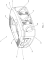
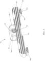
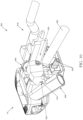
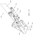
- FIG. 1 illustrates an embodiment of expandable spinal implant 10 provided in accordance with the present disclosure.
- Expandable spinal implant 10 includes an upper body 100 , a lower body 200 , and a ratchet 300 .
- a ratchet screw 400 a ratchet screw 400 , an insertion instrument 500 ( FIG. 7 ), a washer 11 , a locating pin 12 , and a hinge pin 13 are illustrated.
- Upper and lower bodies 100 , 200 cooperate to define a two part expandable spinal implant configured for positioning between adjacent vertebral bodies.
- Bone screws 14 FIGS.
- Ratchet 300 and ratchet screw 400 cooperate to provide a locking mechanism to lock upper and lower bodies 100 , 200 in an articulated position relative to each other, thereby effectuating adjustment of lordosis of the spine.
- upper and lower bodies 100 , 200 may be formed from a metallic material (e.g., titanium, titanium alloy, or cobalt chrome (CoCr)) or a non-metallic material (e.g., polymeric materials such as polyetheretherketone (PEEK), nylon absorbable polymers such as polyglycolides, polylactides, polycaprolactone, etc., or organic materials such as bone).
- Bone screw 14 may be formed from titanium, titanium alloy, CoCr or other suitable metal that is compatible with expandable spinal implant 10 .
- upper body 100 is illustrated as having generally a D-shape; however, it is contemplated that upper body 100 may include other shapes, such as square, rectangular, circular, or the like.
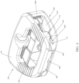
- Upper body 100 includes a substantially contoured first end surface 102 ( FIG. 4 ) at a distal or leading end 104 and a second end surface 106 opposite thereto at a proximal or trailing end 108 .
- Upper body 100 extends between the first and second end surfaces 102 , 106 to define respective top and bottom surfaces 110 , 112 , as well as opposed side surfaces 114 , 116 . As illustrated in FIGS.
- top and bottom surfaces 110 , 112 engage side surfaces 114 , 116 , respectively, to provide a substantially quadrilateral cross-section with rounded corners 118 on an upper end thereof.
- upper body 100 is illustrated as having rounded corners 118 extending around the entire perimeter thereof, it is contemplated that only the intersection of the proximal and distal end surfaces 102 , 106 and top surface 110 includes rounded corners 118 .
- Top surface 110 is generally shown as approximating bottom surface 112 in a direction from trailing end 108 to leading end 104 ; however, it is contemplated that top surface 110 may be parallel to bottom surface 112 .
- First lumen 100a is defined through top and bottom surface 110 , 112 . Although shown as generally having a complimentary shape to that of body 100 , it is contemplated that first lumen 100a may have any suitable shape, such as square, oval, circular, or the like.
- upper surface 110 defines a plurality of ridges 120 arranged thereon. Ridges 120 are configured to frictionally engage an adjacent surface of a vertebral body (i.e., a vertebral endplate) to maintain expandable spinal implant 10 in a position relative to the adjacent vertebral body and to inhibit expandable spinal implant 10 from backing out of the intervertebral space since the ridges 120 will bite into the adjacent vertebral endplate.
- a vertebral body i.e., a vertebral endplate
- Bottom surface 112 is generally planar and includes a plurality of retainers 122 extending normally therefrom.
- Retainers 122 include tabs 122a , 122b , 122c , and 122d , having a generally L-shaped profile (i.e., a vertical member intersecting a horizontal member) and are configured and/or adapted to retain feet 302b ( FIG. 3 ) of ratchet 300 therein.
- Retainers 122 are arranged in opposed pairs such that tabs 122a and 122b are disposed adjacent to side surface 116 and tabs 122c and 122d are disposed adjacent to side surface 114 ( FIG.
- T-shaped channel 142 configured to engage feet 302b ratchet 300 such that ratchet 300 is translatably supported therein.
- tabs 112a , 122c may be recessed from each of side surfaces 114 , 116 or protruding therefrom.
- Hinge 126 extends normal from bottom surface 112 of upper body 100 adjacent to leading end 104 ( FIG . 1 ). Hinge 126 is centrally located between each of side surfaces 114 ( FIG. 1 ), 116 and includes end surfaces 126a and 126b . Through-hole 128 is defined through each of end surfaces 126a and 126b and is configured and/or adapted to receive hinge pin 13 such that hinge pin is rotatably supported therein. Although generally shown as extending partially towards each of side surfaces 114 , 116 , it is contemplated that end surfaces 126a , 126b may be co-planar with side surfaces 114 , 116 and a recess may be defined within a center region of hinge 126 .
- Lug 130 extends normal from bottom surface 112 of upper body 100 and is adjacent to trailing end 108 . Lug 130 is centrally located between each of side surfaces 114 , 116 and includes leading face 132 . Opening 134 is defined through each of leading face 132 and second end surface 106 and defines an inner surface 134a and longitudinal axis A-A . Annular groove 136 is defined in the leading end of inner surface 134a and is configured to receive flange 402 of ratchet screw 400 thereby rotatably supporting ratchet screw 400 and preventing ratchet screw 400 from advancing axially along longitudinal axis A-A . Screw hole 138 extends through lug 130 .
- Screw hole 138 is obliquely angled relative to second end surface 106 (e.g., screw hole 138 extends in a non-perpendicular orientation relative to second end surface 106 ) thereby directing bone screw 14 ( FIGS. 6A-6C ) therethrough at a similar oblique angle towards one of the vertebral bodies for engagement of bone screw 14 within the vertebral body despite upper body 100 being vertically displaced (e.g., vertically offset, relative to the vertebral body into which the bone screw 14 extending through screw hole 138 is to engage). Screw hole 138 further defines counterbore 138a disposed therein terminating in lip 138b .
- Lip 138b is configured and/or adapted to engage thread 16b of head 16 of bone screw 14 thereby retaining bone screw 14 within screw hole 138 and preventing bone screw 14 from backing out of screw hole 138 .
- bone screw 14 may be formed from a titanium alloy (e.g., Ti-6A1-4V) and the lip 138b is formed of a softer compatible material, such as unalloyed titanium.
- the thread 16b engages the lip 138b .
- the lip 138b is formed from a softer material than the bone screw 14 , advancement of the bone screw 14 through the screw hole 138 results in the thread 16b deforming the lip 138b such that the bone screw 14 resists backing out of the screw hole 138 .
- Each boss 140 includes a threaded bore 140a defined therethrough configured and/or adapted to engage guide screws 502 of insertion instrument 500 ( FIG. 7 ).
- Through-bore 144 ( FIG. 2A ) is defined through second end surface 106 and leading face 132 on an upper end of lug 130 and is configured and or adapted to receive locating pin 12 such that locating pin 12 is frictionally engaged therein.
- Through-bore 144 , locating pin 12, and locating bore 310 ( FIG. 3 ) cooperate to translatably support ratchet 300 on locating pin 12 .
- lower body 200 is illustrated as having a shape complimentary to that of upper body 100 .
- Lower body 200 includes a substantially contoured first end surface 202 at a distal or leading end 204 ( FIG. 5 ) and a second end surface 206 opposite thereto at a proximal or trailing end 208 .
- Lower body 200 extends between the first and second end surfaces 202 , 206 to define respective top and bottom surfaces 210 ( FIG. 4 ), 212 , as well as opposed side surfaces 214 ( FIG. 4 ), 216 . As illustrated in FIG.
- top and bottom surfaces 210 , 212 engage side surfaces 214 , 216 , respectively, to provide a substantially quadrilateral cross-section with rounded corners 218 on an upper end thereof.
- lower body 200 is illustrated as having rounded corners 218 extending around the entire perimeter thereof, it is contemplated that only the intersection of the proximal and distal end surfaces 202 , 206 and bottom surface 212 includes rounded corners 218 .
- Bottom surface 212 is generally shown as approximating top surface 210 in a direction from trailing end 208 to leading end 204 ( FIG. 5 ); however, it is contemplated that bottom surface 212 may be parallel to top surface 210 .
- Second lumen 200a is defined through top and bottom surfaces 210 , 212 . Although shown as generally having a complimentary shape to that of first lumen 100a of upper body 100 , it is contemplated that second lumen 200a may have any suitable shape different than that of first lumen 100a , such as square, oval, circular, or the like.
- bottom surface 212 defines a plurality of ridges 220 arranged thereon. Ridges 220 are configured to frictionally engage an adjacent surface of a vertebral body (i.e., a vertebral endplate) to maintain expandable spinal implant 10 in a position relative to the adjacent vertebral body and to inhibit expandable spinal implant 10 from backing out of the intervertebral space since the ridges 220 will bite into the adjacent vertebral endplate.
- a vertebral body i.e., a vertebral endplate
- slot 226 is defined within top surface 210 adjacent to proximal end surface 202 .
- Slot 226 is centrally located between side surfaces 214 , 216 ( FIG. 2 ) and extends normal from proximal end surface 202 such that hinge 126 may be disposed therein.
- Aperture 228 is defined through each of side surfaces 214 , 216 adjacent to leading end 204 and is configured and/or adapted to receive hinge pin 13 .
- aperture 228 is dimensioned to rotatably support hinge pin 13 while the opposing end of aperture 228 is dimensioned to frictionally engage hinge pin 13 , thereby capturing hinge pin 13 therein and permitting upper body 100 and lower body 200 to be articulated relative to each other about hinge pin 13 from a closed, approximated position, to a plurality of open (articulated) positions.
- Opposing lugs 230a , 230b are disposed on top surface 210 adjacent to each of side surfaces 214 , 216 respectively and extend normal therefrom. Opposing lugs 230a , 230b are separated such that lug 130 may be disposed therein when upper body and lower body are in an approximated configuration.
- a plurality of teeth 232 is disposed on a leading face of opposing lugs 230a , 230b and is configured to engage teeth 302 of ratchet 300 .
- a plurality of screw holes 238 extend through each of opposing lugs 230a , 230b and have a similar configuration to that of screw hole 138 with lips 238b .
- the interaction between the bone screw 14 and the lip 238b is substantially similar to the interaction between the bone screw 14 and the lip 138b that was discussed hereinabove. Therefore, in the interest of brevity, screw holes 238 will not be described in detail herein.
- the plurality of screw holes 138 , 238 may include a locking device (not shown) to retain bone screw 14 therein.
- the locking device may be any suitable locking device, such as a locking clip, locking plate, an additional screw, or the like.
- a plurality of threaded bores 240 ( FIG. 2 ) is defined through second end surface 206 on each of opposing lugs 230a , 230b respectively. Threaded bores 240 are configured and/or adapted to engage guide screws 502 of insertion instrument 500 ( FIG. 9 ).
- ratchet 300 having a generally T-shaped configuration.
- Threaded through-hole 305 extends through leg 308 and defines longitudinal axis B-B .
- Ratchet 300 is oriented relative to upper body 100 such that longitudinal axis B-B is coaxial with longitudinal axis A-A .
- Threaded through-hole 305 is configured to threadably engage threaded shank 400b of ratchet screw 400 such that ratchet 300 may be translated axially along axis B-B as ratchet screw 400 is rotated.
- Teeth 302 are disposed on a trailing edge 304 of ratchet 300 and are configured and/or adapted to engage teeth 232 of lower body 200 as ratchet 300 is advanced axially along axis A-A toward the leading face of opposing lugs 230a , 230b . Once engaged, teeth 302 and 232 maintain lower body 200 and upper body 100 in a selected position relative to each other.
- Locating bore 310 extends through leg 308 and is configured to receive locating pin 12 such that ratchet 300 is translatably supported thereon. Locating bore 310 , in conjunction with locating pin 12 and channel 142 ( FIG. 2A ) of upper body 100 , serves to locate ratchet 300 relative to upper body 100 to maintain the coaxial alignment of axes A-A and B-B .
- a pair of legs 302a is disposed on opposing sides of the underside of ratchet 300 .
- Legs 302a extend normal from the underside of ratchet 300 and have a generally T-shaped configuration, complimentary to T-shaped channel 142 of upper body 100 , defining feet 302b .
- Feet 302b are configured to engage tabs 122a , 122b , 122c , and 122d of upper body 100 such that ratchet 300 is translatably supported along axis B-B .
- T-shaped channel 142 FIG.
- T-shaped channel 142 and feet 302b translatably support the lower side of ratchet 300
- locating bore 310 and locating pin 12 translatably support the upper side of ratchet 300 , thereby maintaining coaxial alignment of axes A-A and B-B and preventing any binding that may occur during translation of ratchet 300 relative to upper body 100 .
- ratchet screw 400 having proximal and distal ends, includes a head 400a on the proximal end and a threaded shank 400b extending distally therefrom.
- Head 400a of ratchet screw 400 defines a tool-engaging recess 400c .
- Tool-engaging recess 400c may have any shape and/or dimension suitable for transmitting rotational motion from a tool to ratchet screw 400 (e.g., square, hex, pozidrive, or the like).
- Ratchet screw 400 is configured to be threaded into threaded bore 305 of ratchet 300 .
- Flange 402 is disposed adjacent to head 400a and is configured to engage annular groove 136 of lug 130 such that ratchet screw 400 is rotatably supported within annular groove 136 thereby causing ratchet 300 to translate axially in a first direction along axis B-B as ratchet screw 400 is rotated in a first direction.
- the distal end of ratchet screw 400 includes an unthreaded portion 404 disposed on the shank configured to engage washer 11 .
- Washer 11 is configured and/or dimensioned to be advanced over the unthreaded portion 404 of ratchet screw 400 and engage the leading edge of ratchet 300 such that when ratchet screw 400 is rotated in a second direction, washer 11 abuts the leading edge of ratchet 300 and advances ratchet 300 axially in a second direction along axis B-B . Washer 11 is retained on the unthreaded portion 404 of ratchet screw 400 by any means known in the art, such as bonding, welding, etc.
- FIGS. 6A-C an illustration of bone screw 14 configured for use with expandable spinal implant 10 is shown.
- a plurality of bone screws 14 is configured to secure each of upper and lower bodies 100 , 200 of expandable spinal implant 10 to adjacent vertebral bodies.
- bone screws 14 are similar to one another, only one is described in detail herein. It is also contemplated that other suitable bone screws 14 be provided for use with expandable spinal implant 10 .
- Bone screw 14 generally includes a shank 15 and a head 16 .
- Shank 15 defines a distal tip 15a and pitched threading 15b disposed about shank 15 .
- Distal tip 15a and pitched threading 15b facilitate driving bone screw 14 into bone and securement of bone screw 14 therein.
- Head 16 of bone screw 14 defines a tool-engaging recess 16a .
- Head 16 further includes a thread 16b for threadably engaging lip 138b , 238b of upper and lower bodies 100 , 200 respectively.
- Pitched threading 15a has a pitch greater than that of thread 16b .
- Tool-engaging recess 16a may have any shape and/or dimension suitable for transmitting rotational motion from a tool to bone screw 14 (e.g., square, hex, pozidrive, or the like).
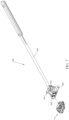
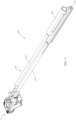
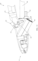
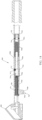
- Insertion instrument 500 includes first body 504 and second body 506 , which are pivotably connected at a first end such that first and second body 504 , 506 are operable to be positioned in an expanded state ( FIG. 11 ), or an approximated state ( FIG. 7 ).
- First body 504 includes an elongate handle 508 extending proximally therefrom, defining a tool lumen 510 therethrough ( FIG. 9 ).
- Tool lumen 510 is adapted to receive any suitable tool (not shown) capable of engaging tool engaging recess 400c of ratchet screw 400 for transmitting rotational motion thereto.
- Guide bores 512 are defined through first body 504 and second body 506 , and are arranged at corresponding angles to that of screw holes 138 , 238 such that when insertion instrument 500 is secured to expandable spinal implant 10 , bone screws 14 may be advanced through guide bores 512 and thereafter, screw holes 138 , 238 .
- Guide screws 502 are insertable through corresponding through-bores (not shown) of first and second bodies 504 , 506 , and are adapted to be threadably received within corresponding threaded bores 140a , 240 of upper and lower bodies 100 , 200 respectively.
- Guide pins 516 are disposed on opposing side surfaces of second body 506 and are configured to engage slots 522 of upper handle 518 ( FIG. 10 ).
- Upper handle 518 is selectably engageable with guide pins 516 and guide screws 502 of second body 506 .
- Apertures 520 are defined through a distal end of upper handle 518 and are configured to receive guide screws 502 of second body 506 therein.
- Slots 522 are disposed on opposing side surfaces of the distal end of upper handle 518 and are configured to receive guide pins 516 therein.
- Upper handle 518 includes an elongate body 518a extending proximally and terminating at a proximal end 518b , such that a clinician may grasp the proximal end 518b of upper handle 518 and the proximal end of elongate handle 508 and manipulate upper handle 518 and elongate handle 508 relative to each other.
- Upper handle 518 , guide screws 502 , and slots 522 cooperate to allow a clinician to manipulate upper handle 518 and elongate handle 508 relative to each other to effectuate expansion of expandable spinal implant 10 .
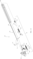
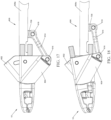
- insertion instrument 600 includes first body 602 and second body 604 , which are operable to be positioned in an expanded state ( FIG. 18 ), or an approximated state ( FIG. 17 ).
- First body 602 includes an elongate handle 606 extending proximally therefrom, defining a lumen 608 therethrough ( FIG. 13 ).
- Locating bores 610 are defined through an outer surface 606a and a portion of an inner surface of lumen 608 of elongate handle 606 in a direction normal to lumen 608.
- Locating bores 610 are adapted to frictionally retain locating pins 714 such that locating pins 714 are flush with the outer surface 606a .
- Locating pins 714 may be any suitable pin, such as a dowel, a roll pin, a rivet, or the like.
- Through-hole 612 ( FIG. 14 ) is defined through outer surface 606a and is adapted to frictionally retain limiting pin 712 .
- Limiting pin 712 may be any suitable pin, such as a dowel, a roll pin, a rivet, or the like.
- adjustment assembly 700 is disposed within lumen 608 and generally includes an adjustment nut 702 , a coupler 704 , a threaded barrel 706 , a shuttle 708 , a retaining clip 710 , limiting pin 712 , and locating pins 714 .
- Adjustment nut 702 is adapted to be received within lumen 608 and includes a tool receiving portion 702a defined within a proximal end thereof.
- Internal threads 702b are disposed on an interior surface of the distal end of a throughbore 702c defined through adjustment nut 702 .
- adjustment nut 702 includes an annular groove 702d defined thereon adapted to receive a portion of locating pins 714 .
- annular groove 702d defined thereon adapted to receive a portion of locating pins 714 .
- Coupler 704 includes a through-hole 704a defined through proximal and distal ends.
- the proximal end of coupler 704 includes a threaded outer surface 704b adapted to threadably engage internal threads 702b of adjustment nut 702 .
- the distal end of coupler 704 includes threads 704c disposed on an inner surface of through-hole 704a .
- a first slot 704d is defined through an outer surface of coupler 704 and extends longitudinally along through-hole 704a .
- a second slot 704e is defined through an opposing side of the outer surface of coupler 704 and extends longitudinally along through-hole 704a .
- First slot 704d is adapted to slidably receive limiting pin 712 such that when coupler 704 is translated along lumen 608 by rotation of adjustment nut 702 , limiting pin 702 abuts the proximal or distal end of first slot 704d , thereby limiting the longitudinal motion of coupler 704 .
- Shuttle 708 includes a threaded bore 708a defined therethrough and a flange 708b extending normally therefrom. Threaded bore 708a is adapted to be rotatably supported on shank 706b of threaded barrel 706 .
- Threaded barrel 706 includes a threaded outer surface 706a disposed on a proximal end thereof and a hexagonal through-bore 706c defined therethrough. Hexagonal through-bore 706c is adapted to engage a suitable tool capable of effectuating rotational motion. Threaded barrel 706a transitions to a smooth shank 706b located on a distal end of threaded barrel 706 .
- Smooth shank 706b transitions to a flange 706d having a diameter greater than that of smooth shank 706b .
- Retaining clip 710 is disposed within an annular groove 706e defined in an outer surface of smooth shank 706b .
- Retaining clip 710 may be any suitable clip, such as a circlip, a spring clip, or the like.
- Shuttle 708 is longitudinally retained between flange 706d and retaining clip 710 .
- Threaded outer surface 706a is adapted to threadably engage threads 704c of coupler 704 . Once entirely threaded therein, the proximal end of threaded outer surface 706a is mechanically secured to threads 704c by any suitable means, such as staking, welding, or the like.
- Link 614 includes a first transverse pivot hole 614a defined through opposing sides of a distal end thereof.
- a channel 614b is defined through a proximal end of link 614 and is adapted to slidably receive flange 708b therein.
- a second transverse pivot hole 614c is defined through opposing sides of a proximal end of link 614 .
- First and second bodies 602 , 604 are similar to first and second bodies 504 , 506 , respectively, and therefore, in the interest of brevity, only the differences therebetween will be described in detail herein.
- second body 604 includes a slot 604a defined through a proximal end thereof adapted to slidably receive a distal end of link 614 .
- Retaining bores 604b are disposed through side surfaces of second body 604 and are adapted to frictionally receive a first link pin 616 .
- link 614 is rotatably secured to second body 604 .
- a second link pin 618 is adapted to be received within a pivot hole 708c defined through flange 708b and second transverse pivot hole 614c of link 614 such that link 614 is rotatably supported thereon.
- a pair of transverse through-bores 604c is defined through opposing side surfaces of second body 604 and are adapted to frictionally receive a corresponding first pair of pins 620 .
- Pins 620 are adapted to partially engage a respective annular groove 622a disposed on a shank 622b of retaining screws 622 and may be any suitable pin, such as a dowel pin, a roll pin, a rivet, or the like.
- Retaining screws 622 are similar to guide screws 502 except for annular groove 622a . When fully inserted, retaining screws 622 are longitudinally fixed by pins 620 while still permitting retaining screws 622 to rotate axially.
- First body 602 includes a pair of holes 602a disposed within a lower surface thereof. Holes 602a are adapted to receive a corresponding second pair of pins 624 . Pins 624 are adapted to partially engage a respective annular groove 622a disposed on a shank 622b of retaining screws 622 and may be any suitable pin, such as a dowel pin, a roll pin, a rivet, or the like. When fully inserted, retaining screws 622 are longitudinally fixed by pins 624 while still permitting retaining screws 622 to rotate axially.
- Elongate handle 606 , guide screws 502 , link 614 , and adjustment assembly 700 cooperate to allow a clinician to effectuate expansion of expandable spinal implant 10 as will be discussed in further detail herein.
- ratchet 300 is placed in a first, unengaged position by rotating ratchet screw 400 in a first direction using a suitable tool inserted within tool-engaging recess 400c of ratchet screw 400 .
- upper body 100 is manipulated relative to lower body 200 such that upper body and lower body 100 , 200 are in a first, approximated, position.
- ratchet screw 400 is rotated in a second, opposite direction, drawing teeth 302 of ratchet 300 into engagement with teeth 232 of lower body 200 such that the position of upper body 100 relative to lower body 200 is fixed.
- the intervertebral space is then prepared, e.g., damaged or diseased tissue is removed. Thereafter, the interior space of lumens 100a , 200a of upper and lower body 100 , 200 , respectively, may be packed with bone in-growth material, drugs, or other suitable materials or compounds.
- expandable spinal implant 10 is affixed to a insertion instrument 500 by threadably engaging guide screws 502 to threaded bores 140a , 240 disposed on upper body 100 and lower body 200 respectively ( FIGS. 7-8 ). At this point, expandable spinal implant 10 may be advanced within an incision within the patient and thereafter, a previously prepared intervertebral space of the patient's spine. Bone screws 14 ( FIGS.
- a suitable tool may be advanced within tool lumen 510 ( FIG. 9 ) of insertion tool 500 and thereafter ratchet screw 400 .
- Ratchet screw 400 may be rotated in the first direction to disengage teeth 302 of ratchet 300 from teeth 232 of lower body 200 .
- upper body 100 and lower body 200 may be articulated about hinge pin 13 to a desired location by manipulating upper handle 518 and elongate handle 508 relative to each other ( FIG. 11 ). Articulation of upper body 100 and lower body 200 relative to each other effectuates lordosis of the spine.
- upper body 100 and lower body 200 may be articulated relative to each other to effectively fill the intervertebral space without effectuating lordosis of the spine.
- the desired location of upper body 100 and lower body 200 is selected based on the desired lordosis of the spine.
- ratchet screw 400 is rotated in the second, opposite, direction to draw teeth 302 of ratchet 300 into engagement with teeth 232 of lower body 200 to lock the position of upper body 100 relative to lower body 200 .
- insertion instrument 500 is disengaged from expandable spinal implant 10 and removed from the incision.
- alternate insertion instrument 600 may be secured to expandable spinal implant 10 by threading retaining screws 622 into threaded bores 140a , 240 ( FIGS. 2 and 2A ) disposed on upper body 100 and lower body 200 respectively ( FIG. 12 ).
- the insertion, locking, and removal of expandable spinal implant 10 using insertion instrument 600 is similar to that using insertion instrument 500 , and therefore, in the interest of brevity, only the differences will be described herein.
- a first suitable tool (not shown) is inserted within lumen 608 of elongate handle 606 and is drawn into engagement with the tool receiving portion 702a of adjustment nut 702 .
- Adjustment nut 702 is then rotated, which, in turn, draws coupler 704 in a proximal direction within lumen 608 of elongate handle 606 .
- coupler 704 is drawn proximally, threaded barrel 706 , and therefore shuttle 708 are also drawn proximally, causing link 614 to impart a proximal force on second body 604 thereby causing second body 604 to rotate relative to first body 602 .
- second body 604 effectuates expansion of expandable spinal implant 10 (see FIGS. 17 and 18 ).
- the first tool is removed from lumen 608 .
- a second suitable tool may be advanced within lumen 608 of insertion tool 600 and advanced through through-hole 704a of coupler 704 , through-bore 706c of threaded barrel 706 , and thereafter ratchet screw 400 .
- the position of upper body 100 relative to lower body 200 may be set prior to inserting expandable spinal implant 10 within the intervertebral space. Thereafter, the position may continue to be manipulated until the desired lordosis is achieved using the procedure previously described above.
- ratchet 300 may be drawn into engagement with teeth 232 of lower body 200 such that lower body 200 may be articulated about hinge pin 13 in a first direction (i.e., ratchet open), but not in a second direction (i.e., preventing upper body 100 and lower body 200 from approximating).
- first direction i.e., ratchet open
- second direction i.e., preventing upper body 100 and lower body 200 from approximating
- This process may be repeated as many times as the procedure requires, whether it be for the same expandable spinal implant 10 or for a plurality of expandable spinal implants 10 as required by the procedure being performed.
Landscapes
- Health & Medical Sciences (AREA)
- Engineering & Computer Science (AREA)
- Biomedical Technology (AREA)
- Orthopedic Medicine & Surgery (AREA)
- Neurology (AREA)
- Transplantation (AREA)
- Heart & Thoracic Surgery (AREA)
- Oral & Maxillofacial Surgery (AREA)
- Cardiology (AREA)
- Vascular Medicine (AREA)
- Life Sciences & Earth Sciences (AREA)
- Animal Behavior & Ethology (AREA)
- General Health & Medical Sciences (AREA)
- Public Health (AREA)
- Veterinary Medicine (AREA)
- Physical Education & Sports Medicine (AREA)
- Prostheses (AREA)
- Surgical Instruments (AREA)
Claims (12)
- Wirbelsäulenimplantat, umfassend:einen oberen Körper (100) und einen unteren Körper (200), die an einem ersten Ende (104) schwenkbar befestigt und relativ zueinander beweglich sind, wobei sowohl der obere Körper als auch der untere Körper so dimensioniert sind, dass sie zwischen zwei Wirbelkörpern installiert werden können, wobei die äußeren Oberflächen des oberen Körpers und des unteren Körpers so eingerichtet sind, dass sie in eine entsprechende Endplatte der beiden Wirbelkörper eingreifen,gekennzeichnet durch:Schraubenlöcher (138, 238), die durch die äußere Oberfläche (110) und eine benachbarte seitliche Oberfläche (106) des oberen Körpers (100) und durch die äußere Oberfläche (212) und eine benachbarte seitliche Oberfläche (206) des unteren Körpers (200) definiert sind, wobei die Schraubenlöcher zu einem jeweiligen benachbarten der beiden Wirbelkörper in einem schrägen Winkel orientiert sind;einen Ratschenmechanismus (300), der gleitend an einem der oberen und unteren Körper angeordnet ist, wobei der Ratschenmechanismus in der Lage ist, in den gegenüberliegenden der oberen und unteren Körper einzugreifen, wodurch eine Bewegung der oberen und unteren Körper relativ zueinander in einer ersten Richtung, aber nicht in einer zweiten Richtung ermöglicht wird; undeine Vielzahl von Knochenschrauben (14), wobei jede Knochenschraube der Vielzahl von Knochenschrauben durch ein entsprechendes Schraubenloch (138, 238) des Oberkörpers (100) und des Unterkörpers (200) einführbar ist, wobei die Vielzahl von Knochenschrauben am Knochen angebracht werden kann.
- Wirbelsäulenimplantat nach Anspruch 1, wobei der obere Körper (100) ein erstes Lumen (100a) und der untere Körper (200) ein zweites Lumen (200a) aufweist.
- Wirbelsäulenimplantat nach Anspruch 1, wobei die äußere Oberfläche (110, 212) des Oberkörpers (100) und des Unterkörpers (200) ferner eine Vielzahl von Rippen (120, 220) einschließt, die so eingerichtet sind, dass sie jeweils mit einem der beiden Wirbelkörper in Eingriff kommen.
- Wirbelsäulenimplantat nach Anspruch 1, wobei der untere Körper (200) ein Paar Schraubenlöcher (238) und der obere Körper (100) ein einzelnes Schraubenloch (138) einschließt.
- Wirbelsäulenimplantat nach Anspruch 1, das ferner eine Ratschenschraube (400) einschließt, die drehbar in einer ringförmigen Nut (136) gestützt wird, die in dem unteren Körper (200) definiert ist, wobei die Ratschenschraube einen Kopf (400a) und einen sich davon erstreckenden Gewindeschaft (400b) aufweist, wobei die Ratschenschraube mit einem Gewinde in einem Gewindedurchgangsloch (305) in Eingriff steht, das durch den Ratschenmechanismus (300) definiert ist, wobei eine Rotation der Schraube in einer ersten Richtung eine Bewegung des Ratschenmechanismus in einer ersten Richtung bewirkt und eine Rotation der Schraube in einer zweiten, entgegengesetzten Richtung eine Bewegung des Ratschenmechanismus in einer zweiten, entgegengesetzten Richtung bewirkt.
- Wirbelsäulenimplantat nach Anspruch 1, das ferner eine Vielzahl von Gewindebohrungen (140a, 240) einschließt, die durch eine Endoberfläche (106, 206) sowohl des oberen als auch des unteren Körpers (100, 200) definiert sind, wobei die Vielzahl von Gewindebohrungen so konfiguriert ist, dass sie in ein Einführungsinstrument (500, 600) eingreifen, das das Wirbelsäulenimplantat zwischen die beiden Wirbelkörper einführen kann.
- Wirbelsäulenimplantat nach Anspruch 1, ferner einschließend einen Lokalisierungsstift (12), der in einer durch eine Seitenfläche (106) des unteren Körpers (200) definierten Durchgangsbohrung (144) und einer durch den Ratschenmechanismus (300) definierten Lokalisierungsbohrung (310) angeordnet ist, wobei die Durchgangsbohrung und die Lokalisierungsbohrung koaxial ausgerichtet sind, wobei der Lokalisierungsstift in Reibungseingriff mit der Durchgangsbohrung steht, wodurch der Lokalisierungsstift darin gehalten wird, wobei der Ratschenmechanismus verschiebbar auf dem Lokalisierungsstift gestützt ist.
- Wirbelsäulenimplantat nach Anspruch 1, wobei der Ratschenmechanismus (300) ein Paar von Beinen (302a) einschließt, die sich von seiner Unterseite aus erstrecken, wobei das Paar von Beinen so konfiguriert ist, dass es in ein entsprechendes Paar von Kanälen (142) eingreift, die auf der inneren Oberfläche (112) des Oberkörpers (100) angeordnet sind, wodurch der Ratschenmechanismus darin verschiebbar gestützt wird.
- Wirbelsäulenimplantat nach Anspruch 1, wobei der obere Körper (100) und der untere Körper (200) über einen Gelenkstift (13), der in einer am ersten Ende (204) des unteren Körpers (200) definierten Aussparung (228) angeordnet ist, und ein am ersten Ende (104) des oberen Körpers (100) definiertes Durchgangsloch (128) schwenkbar gekoppelt sind, wobei der Gelenkstift reibschlüssig mit einem der ersten oder zweiten Enden der Aussparung in Eingriff steht und dadurch den Gelenkstift darin hält.
- Wirbelsäulenimplantat nach Anspruch 1, wobei der Ratschenmechanismus (300) gleitend auf einer inneren Oberfläche (112) des Oberkörpers (100) angeordnet ist, wobei der Ratschenmechanismus eine erste Vielzahl von Zähnen (302) einschließt, die darauf angeordnet sind.
- Wirbelsäulenimplantat nach Anspruch 10, wobei der untere Körper (200) eine zweite Vielzahl von Zähnen (232) einschließt, die auf einer inneren Oberfläche (210) gegenüber dem Ratschenmechanismus (300) des oberen Körpers (100) angeordnet sind, wobei die zweite Vielzahl von Zähnen so konfiguriert ist, dass sie in die erste Vielzahl von Zähnen (302) des Ratschenmechanismus eingreift.
- Wirbelsäulenimplantat nach Anspruch 11, wobei die erste und die zweite Vielzahl von Zähnen (302, 232) so ausgerichtet sind, dass die erste und die zweite Vielzahl von Zähnen in einer ersten Richtung gleitend ineinandergreifen und in einer zweiten Richtung an einer Bewegung relativ zueinander gehindert werden, wodurch die Position des oberen Körpers (100) und des unteren Körpers (200) relativ zueinander fixiert wird.
Applications Claiming Priority (2)
| Application Number | Priority Date | Filing Date | Title |
|---|---|---|---|
| US14/510,598 US9585762B2 (en) | 2014-10-09 | 2014-10-09 | Expandable spinal interbody spacer and method of use |
| PCT/US2015/054969 WO2016057940A1 (en) | 2014-10-09 | 2015-10-09 | Expandable spinal interbody spacer and method of use |
Publications (3)
| Publication Number | Publication Date |
|---|---|
| EP3203939A1 EP3203939A1 (de) | 2017-08-16 |
| EP3203939A4 EP3203939A4 (de) | 2018-09-26 |
| EP3203939B1 true EP3203939B1 (de) | 2023-08-23 |
Family
ID=55653864
Family Applications (1)
| Application Number | Title | Priority Date | Filing Date |
|---|---|---|---|
| EP15849152.2A Active EP3203939B1 (de) | 2014-10-09 | 2015-10-09 | Interkorporelles distanzstück |
Country Status (4)
| Country | Link |
|---|---|
| US (4) | US9585762B2 (de) |
| EP (1) | EP3203939B1 (de) |
| AU (2) | AU2015330678B2 (de) |
| WO (1) | WO2016057940A1 (de) |
Families Citing this family (69)
| Publication number | Priority date | Publication date | Assignee | Title |
|---|---|---|---|---|
| WO2013052807A2 (en) | 2011-10-05 | 2013-04-11 | H. Lee Moffitt Cancer Center And Research Institute, Inc. | Bone fusion system |
| WO2014089535A1 (en) | 2012-12-07 | 2014-06-12 | Providence Medical Technology, Inc. | Apparatus and method for bone screw deployment |
| US11311312B2 (en) | 2013-03-15 | 2022-04-26 | Medtronic, Inc. | Subcutaneous delivery tool |
| WO2014189890A1 (en) | 2013-05-20 | 2014-11-27 | K2M, Inc. | Adjustable implant and insertion tool |
| US9585762B2 (en) | 2014-10-09 | 2017-03-07 | K2M, Inc. | Expandable spinal interbody spacer and method of use |
| US10149710B2 (en) * | 2015-05-11 | 2018-12-11 | Providence Medical Technology, Inc. | Bone screw and implant delivery device |
| EP3294166B1 (de) * | 2015-05-11 | 2026-01-28 | Providence Medical Technology, Inc. | Knochenschraube und implantateinführungsvorrichtung |
| US10500061B2 (en) * | 2015-08-13 | 2019-12-10 | K2M, Inc. | Adjustable spinal implant |
| US10004608B2 (en) | 2016-02-26 | 2018-06-26 | K2M, Inc. | Insertion instrument for expandable spinal implants |
| JP6995789B2 (ja) | 2016-06-28 | 2022-01-17 | イーアイティー・エマージング・インプラント・テクノロジーズ・ゲーエムベーハー | 拡張可能かつ角度調節可能な椎間ケージ |
| CN109640889B (zh) | 2016-06-28 | 2021-07-30 | Eit 新兴移植技术股份有限公司 | 可扩张的角度可调节式关节运动椎间保持架 |
| EP3487448B1 (de) * | 2016-07-21 | 2024-08-28 | Seaspine, Inc. | Expandierbares implantat |
| WO2018049227A1 (en) | 2016-09-08 | 2018-03-15 | Mayo Foundation For Medical Education And Research | Spinal fixation system |
| IT201600105751A1 (it) * | 2016-10-20 | 2018-04-20 | Medacta Int Sa | Gabbia di fusione intervertebrale |
| US11701239B2 (en) | 2017-01-26 | 2023-07-18 | Loubert S. Suddaby | Stand-alone expandable interbody spinal fusion device with integrated fixation mechanism |
| US11207192B2 (en) * | 2017-01-26 | 2021-12-28 | Loubert S. Suddaby | Stand-alone expandable interbody spinal fusion device with integrated fixation mechanism |
| US10398563B2 (en) | 2017-05-08 | 2019-09-03 | Medos International Sarl | Expandable cage |
| US11207135B2 (en) | 2017-07-12 | 2021-12-28 | K2M, Inc. | Systems and methods for modeling spines and treating spines based on spine models |
| US11000334B1 (en) | 2017-07-12 | 2021-05-11 | K2M, Inc. | Systems and methods for modeling spines and treating spines based on spine models |
| EP3651637B1 (de) | 2017-07-12 | 2025-07-09 | Stryker Corporation | Systeme zur modellierung von wirbelsäulen und zur behandlung von wirbelsäulen auf der grundlage von wirbelsäulenmodellen |
| US10892058B2 (en) | 2017-09-29 | 2021-01-12 | K2M, Inc. | Systems and methods for simulating spine and skeletal system pathologies |
| US10874460B2 (en) | 2017-09-29 | 2020-12-29 | K2M, Inc. | Systems and methods for modeling spines and treating spines based on spine models |
| EP3755273B1 (de) | 2018-02-22 | 2025-04-30 | Warsaw Orthopedic, Inc. | Expandierbares wirbelsäulenimplantatsystem |
| CN111655203A (zh) * | 2018-02-22 | 2020-09-11 | 华沙整形外科股份有限公司 | 可扩展脊柱植入物系统及其使用方法 |
| US11806250B2 (en) | 2018-02-22 | 2023-11-07 | Warsaw Orthopedic, Inc. | Expandable spinal implant system and method of using same |
| US11337829B2 (en) | 2018-03-09 | 2022-05-24 | K2M, Inc. | Devices for inserting and expanding spinal implants |
| US11636650B2 (en) | 2018-09-24 | 2023-04-25 | K2M, Inc. | System and method for isolating anatomical features in computerized tomography data |
| US11298244B2 (en) * | 2019-01-31 | 2022-04-12 | K2M, Inc. | Interbody implants and instrumentation |
| USD948048S1 (en) | 2019-04-26 | 2022-04-05 | Warsaw Orthopedic, Inc. | Surgical implant |
| USD955579S1 (en) | 2019-04-26 | 2022-06-21 | Warsaw Orthopedic, Inc. | Surgical implant |
| GB201910668D0 (en) | 2019-07-25 | 2019-09-11 | Axis Spine Tech Ltd | Assemblies for and methods of determing height and angle of an intervertebral device |
| GB201910640D0 (en) | 2019-07-25 | 2019-09-11 | Axis Spine Tech Ltd | Insertions instruments |
| WO2021055323A1 (en) * | 2019-09-16 | 2021-03-25 | Mayo Foundation For Medical Education And Research | Spinal fixation system and kit |
| US11534307B2 (en) | 2019-09-16 | 2022-12-27 | K2M, Inc. | 3D printed cervical standalone implant |
| KR102147077B1 (ko) | 2019-10-07 | 2020-08-24 | (주)엘앤케이바이오메드 | 높이조절이 가능한 척추 유합 케이지 |
| US11426286B2 (en) | 2020-03-06 | 2022-08-30 | Eit Emerging Implant Technologies Gmbh | Expandable intervertebral implant |
| KR102117224B1 (ko) | 2020-03-06 | 2020-06-01 | (주)엘앤케이바이오메드 | 높이조절이 가능한 척추 유합 케이지 |
| KR102489197B1 (ko) | 2020-05-25 | 2023-01-17 | (주)엘앤케이바이오메드 | 높이조절이 가능한 척추 유합 케이지 |
| US11395743B1 (en) | 2021-05-04 | 2022-07-26 | Warsaw Orthopedic, Inc. | Externally driven expandable interbody and related methods |
| US11517443B2 (en) | 2020-11-05 | 2022-12-06 | Warsaw Orthopedic, Inc. | Dual wedge expandable implant, system and method of use |
| US11963881B2 (en) | 2020-11-05 | 2024-04-23 | Warsaw Orthopedic, Inc. | Expandable inter-body device, system, and method |
| US12318308B2 (en) | 2020-11-05 | 2025-06-03 | Warsaw Orthopedic, Inc. | Dual expandable inter-body device |
| US11376134B1 (en) | 2020-11-05 | 2022-07-05 | Warsaw Orthopedic, Inc. | Dual expanding spinal implant, system, and method of use |
| US11564724B2 (en) | 2020-11-05 | 2023-01-31 | Warsaw Orthopedic, Inc. | Expandable inter-body device, system and method |
| US11833059B2 (en) | 2020-11-05 | 2023-12-05 | Warsaw Orthopedic, Inc. | Expandable inter-body device, expandable plate system, and associated methods |
| US12121453B2 (en) | 2020-11-05 | 2024-10-22 | Warsaw Orthopedic, Inc. | Dual wedge expandable implant with eyelets, system, and method of use |
| US12171439B2 (en) | 2020-11-05 | 2024-12-24 | Warsaw Orthopedic, Inc. | Protected drill |
| US12239544B2 (en) | 2020-11-05 | 2025-03-04 | Warsaw Orthopedic, Inc. | Rhomboid shaped implants |
| US11285014B1 (en) | 2020-11-05 | 2022-03-29 | Warsaw Orthopedic, Inc. | Expandable inter-body device, system, and method |
| US11638653B2 (en) | 2020-11-05 | 2023-05-02 | Warsaw Orthopedic, Inc. | Surgery instruments with a movable handle |
| US11291554B1 (en) | 2021-05-03 | 2022-04-05 | Medtronic, Inc. | Unibody dual expanding interbody implant |
| EP4262636A4 (de) * | 2020-12-16 | 2024-11-13 | Amplify Surgical, Inc. | Verankerte zwischenwirbelimplantate |
| US12533240B2 (en) | 2021-03-10 | 2026-01-27 | Amplify Surgical, Inc. | Drive instruments with retention mechanisms, medical implants, and related technologies |
| US11850160B2 (en) | 2021-03-26 | 2023-12-26 | Medos International Sarl | Expandable lordotic intervertebral fusion cage |
| US11752009B2 (en) | 2021-04-06 | 2023-09-12 | Medos International Sarl | Expandable intervertebral fusion cage |
| US12440349B2 (en) | 2021-11-01 | 2025-10-14 | Warsaw Orthopedic, Inc. | Expandable interbody implant and breakoff screw |
| US12485019B2 (en) | 2021-06-24 | 2025-12-02 | Warsaw Orthopedic, Inc. | Parallel jaw inserter |
| US12295865B2 (en) | 2021-06-24 | 2025-05-13 | Warsaw Orthopedic, Inc. | Expandable interbody implant and corresponding inserter |
| WO2022271280A1 (en) | 2021-06-24 | 2022-12-29 | Warsaw Orthopedic, Inc. | Expandable interbody implant and corresponding surgical tool |
| US12268614B2 (en) | 2021-06-24 | 2025-04-08 | Warsaw Orthopedic, Inc. | Interbody implant with adjusting shims |
| US11612499B2 (en) | 2021-06-24 | 2023-03-28 | Warsaw Orthopedic, Inc. | Expandable interbody implant |
| EP4358902A4 (de) * | 2021-06-24 | 2025-04-16 | Warsaw Orthopedic, Inc. | Expandierbares zwischenwirbelimplantat und zugehöriges chirurgisches werkzeug |
| US11730608B2 (en) | 2021-07-13 | 2023-08-22 | Warsaw Orthopedic, Inc. | Monoblock expandable interbody implant |
| JP7749105B2 (ja) * | 2021-08-25 | 2025-10-03 | 25セグメンツ アクチェンゲゼルシャフト | 拡張可能な椎間ケージ |
| US11850163B2 (en) | 2022-02-01 | 2023-12-26 | Warsaw Orthopedic, Inc. | Interbody implant with adjusting shims |
| US12090064B2 (en) | 2022-03-01 | 2024-09-17 | Medos International Sarl | Stabilization members for expandable intervertebral implants, and related systems and methods |
| USD1098431S1 (en) * | 2023-02-27 | 2025-10-14 | Providence Medical Technology, Inc. | Spinal cage |
| US12533241B2 (en) | 2023-05-16 | 2026-01-27 | Warsaw Orthopedic, Inc. | Distracting and angling expandable interbody device |
| USD1098433S1 (en) * | 2023-12-28 | 2025-10-14 | Providence Medical Technology, Inc. | Spinal cage |
Family Cites Families (131)
| Publication number | Priority date | Publication date | Assignee | Title |
|---|---|---|---|---|
| FR2715293B1 (fr) | 1994-01-26 | 1996-03-22 | Biomat | Cage intersomatique vertébrale. |
| FR2717068B1 (fr) | 1994-03-14 | 1996-04-26 | Biomat | Cage intersomatique vertébrale. |
| US5665122A (en) | 1995-01-31 | 1997-09-09 | Kambin; Parviz | Expandable intervertebral cage and surgical method |
| US6190414B1 (en) | 1996-10-31 | 2001-02-20 | Surgical Dynamics Inc. | Apparatus for fusion of adjacent bone structures |
| US6045579A (en) | 1997-05-01 | 2000-04-04 | Spinal Concepts, Inc. | Adjustable height fusion device |
| US6641614B1 (en) | 1997-05-01 | 2003-11-04 | Spinal Concepts, Inc. | Multi-variable-height fusion device |
| DE19804765C2 (de) | 1998-02-06 | 2000-09-28 | Biedermann Motech Gmbh | Platzhalter mit einstellbarer axialer Länge |
| DE19807236C2 (de) | 1998-02-20 | 2000-06-21 | Biedermann Motech Gmbh | Zwischenwirbelimplantat |
| US6126689A (en) | 1998-06-15 | 2000-10-03 | Expanding Concepts, L.L.C. | Collapsible and expandable interbody fusion device |
| FR2782632B1 (fr) | 1998-08-28 | 2000-12-29 | Materiel Orthopedique En Abreg | Cage de fusion intersomatique expansible |
| US6193757B1 (en) * | 1998-10-29 | 2001-02-27 | Sdgi Holdings, Inc. | Expandable intervertebral spacers |
| US6183517B1 (en) | 1998-12-16 | 2001-02-06 | Loubert Suddaby | Expandable intervertebral fusion implant and applicator |
| US6159244A (en) | 1999-07-30 | 2000-12-12 | Suddaby; Loubert | Expandable variable angle intervertebral fusion implant |
| US6102950A (en) | 1999-01-19 | 2000-08-15 | Vaccaro; Alex | Intervertebral body fusion device |
| US6491724B1 (en) | 1999-08-13 | 2002-12-10 | Bret Ferree | Spinal fusion cage with lordosis correction |
| US20040249461A1 (en) | 1999-08-13 | 2004-12-09 | Ferree Bret A. | Coupled artificial disc replacements methods and apparatus |
| BR9917485A (pt) | 1999-09-14 | 2002-05-14 | Spine Solutions Inc | Instrumento de inserção para um implante entre vértebras de três partes |
| US6709458B2 (en) | 2000-02-04 | 2004-03-23 | Gary Karlin Michelson | Expandable push-in arcuate interbody spinal fusion implant with tapered configuration during insertion |
| US6814756B1 (en) | 2000-02-04 | 2004-11-09 | Gary K. Michelson | Expandable threaded arcuate interbody spinal fusion implant with lordotic configuration during insertion |
| US6500205B1 (en) | 2000-04-19 | 2002-12-31 | Gary K. Michelson | Expandable threaded arcuate interbody spinal fusion implant with cylindrical configuration during insertion |
| EP1645248B8 (de) | 2000-02-04 | 2010-06-16 | Warsaw Orthopedic, Inc. | Ausdehnbares interspinales Fusionsimplantat mit schwenkbarem Blocker |
| US6716247B2 (en) | 2000-02-04 | 2004-04-06 | Gary K. Michelson | Expandable push-in interbody spinal fusion implant |
| US6332895B1 (en) | 2000-03-08 | 2001-12-25 | Loubert Suddaby | Expandable intervertebral fusion implant having improved stability |
| US6821298B1 (en) | 2000-04-18 | 2004-11-23 | Roger P. Jackson | Anterior expandable spinal fusion cage system |
| US6808537B2 (en) | 2000-07-07 | 2004-10-26 | Gary Karlin Michelson | Expandable implant with interlocking walls |
| US6454807B1 (en) | 2000-11-30 | 2002-09-24 | Roger P. Jackson | Articulated expandable spinal fusion cage system |
| US6443989B1 (en) | 2000-12-04 | 2002-09-03 | Roger P. Jackson | Posterior expandable fusion cage |
| US6773460B2 (en) | 2000-12-05 | 2004-08-10 | Roger P. Jackson | Anterior variable expandable fusion cage |
| DE60201945T2 (de) | 2001-02-04 | 2005-12-01 | Michelson, Gary Karlin, Los Angeles | Instrument zum Einführen und Spreiten eines Zwischenwirbelfusionsimplantats |
| US6849093B2 (en) * | 2001-03-09 | 2005-02-01 | Gary K. Michelson | Expansion constraining member adapted for use with an expandable interbody spinal fusion implant and method for use thereof |
| US6368351B1 (en) | 2001-03-27 | 2002-04-09 | Bradley J. Glenn | Intervertebral space implant for use in spinal fusion procedures |
| US6648917B2 (en) | 2001-10-17 | 2003-11-18 | Medicinelodge, Inc. | Adjustable bone fusion implant and method |
| US6991653B2 (en) | 2002-03-21 | 2006-01-31 | Sdgi Holdings, Inc. | Vertebral body and disc space replacement devices |
| US20040087947A1 (en) | 2002-08-28 | 2004-05-06 | Roy Lim | Minimally invasive expanding spacer and method |
| US7044971B2 (en) | 2002-08-30 | 2006-05-16 | Loubert Suddaby | Lordotic fusion implant |
| US7588573B2 (en) | 2002-09-23 | 2009-09-15 | Warsaw Orthopedic, Inc. | Expansion tool for adjustable spinal implant |
| US6685742B1 (en) | 2002-11-12 | 2004-02-03 | Roger P. Jackson | Articulated anterior expandable spinal fusion cage system |
| WO2004052245A1 (de) | 2002-12-06 | 2004-06-24 | Synthes Ag Chur | Zwischenwirbelimplantat |
| US7828849B2 (en) | 2003-02-03 | 2010-11-09 | Warsaw Orthopedic, Inc. | Expanding interbody implant and articulating inserter and method |
| FR2850563B1 (fr) | 2003-02-05 | 2005-11-04 | Scient X | Implant de remplacement vertebral et appareil de distraction pour la mise en place de l'implant |
| US7918876B2 (en) | 2003-03-24 | 2011-04-05 | Theken Spine, Llc | Spinal implant adjustment device |
| US7753958B2 (en) | 2003-08-05 | 2010-07-13 | Gordon Charles R | Expandable intervertebral implant |
| US7217293B2 (en) | 2003-11-21 | 2007-05-15 | Warsaw Orthopedic, Inc. | Expandable spinal implant |
| US7217291B2 (en) | 2003-12-08 | 2007-05-15 | St. Francis Medical Technologies, Inc. | System and method for replacing degenerated spinal disks |
| DE502004010737D1 (de) | 2003-12-09 | 2010-03-25 | Biedermann Motech Gmbh | Höheneinstellbares Zwischenwirbelimplantat |
| DE20320974U1 (de) | 2003-12-11 | 2005-08-25 | Deltacor Gmbh | Längenverstellbares Wirbelsäulen-Implantat |
| US7850733B2 (en) | 2004-02-10 | 2010-12-14 | Atlas Spine, Inc. | PLIF opposing wedge ramp |
| US7211112B2 (en) | 2004-02-10 | 2007-05-01 | Atlas Spine | Spinal fusion device |
| US7776091B2 (en) | 2004-06-30 | 2010-08-17 | Depuy Spine, Inc. | Adjustable posterior spinal column positioner |
| US7678148B2 (en) | 2004-07-23 | 2010-03-16 | Warsaw Orthopedic, Inc. | Expandable spinal implant having interlocking geometry for structural support |
| US7799081B2 (en) | 2004-09-14 | 2010-09-21 | Aeolin, Llc | System and method for spinal fusion |
| US20060122701A1 (en) | 2004-11-23 | 2006-06-08 | Kiester P D | Posterior lumbar interbody fusion expandable cage with lordosis and method of deploying the same |
| US7655046B2 (en) | 2005-01-20 | 2010-02-02 | Warsaw Orthopedic, Inc. | Expandable spinal fusion cage and associated instrumentation |
| US20060167547A1 (en) | 2005-01-21 | 2006-07-27 | Loubert Suddaby | Expandable intervertebral fusion implants having hinged sidewalls |
| WO2006105437A2 (en) | 2005-03-31 | 2006-10-05 | Life Spine, Inc. | Expandable spinal interbody and intravertebral body devices |
| US8308802B2 (en) | 2010-01-21 | 2012-11-13 | Globus Medical, Inc. | Expandable vertebral prosthesis |
| US7674296B2 (en) | 2005-04-21 | 2010-03-09 | Globus Medical, Inc. | Expandable vertebral prosthesis |
| US7883542B2 (en) | 2005-06-03 | 2011-02-08 | Zipnick Richard I | Minimally invasive apparatus to manipulate and revitalize spinal column disc |
| US7722674B1 (en) | 2005-08-12 | 2010-05-25 | Innvotec Surgical Inc. | Linearly expanding spine cage for enhanced spinal fusion |
| US7985256B2 (en) | 2005-09-26 | 2011-07-26 | Coalign Innovations, Inc. | Selectively expanding spine cage, hydraulically controllable in three dimensions for enhanced spinal fusion |
| US7794501B2 (en) | 2006-04-27 | 2010-09-14 | Wasaw Orthopedic, Inc. | Expandable intervertebral spacers and methods of use |
| US8187331B2 (en) | 2006-04-27 | 2012-05-29 | Warsaw Orthopedic, Inc. | Expandable vertebral implant and methods of use |
| US7708779B2 (en) | 2006-05-01 | 2010-05-04 | Warsaw Orthopedic, Inc. | Expandable intervertebral spacers and methods of use |
| ATE476157T1 (de) | 2006-06-14 | 2010-08-15 | Eden Spine Europ Sa | Vorrichtung zum wirbelkörperersatz |
| US7771473B2 (en) | 2006-07-06 | 2010-08-10 | Lanx, Inc. | Expandable spinal fusion cage |
| US7731752B2 (en) | 2006-07-21 | 2010-06-08 | Warsaw Orthopedic, Inc. | Implant with nested members and methods of use |
| US20080045968A1 (en) | 2006-08-18 | 2008-02-21 | Warsaw Orthopedic, Inc. | Instruments and Methods for Spinal Surgery |
| WO2008033457A2 (en) | 2006-09-14 | 2008-03-20 | The University Of Toledo | Variable height vertebral body replacement implant |
| US8328871B2 (en) | 2006-11-09 | 2012-12-11 | Warsaw Orthopedic, Inc. | Expanding vertebral body implant |
| ES2339472T3 (es) | 2006-11-23 | 2010-05-20 | Biedermann Motech Gmbh | Implante intervertebral expansible. |
| US8105382B2 (en) | 2006-12-07 | 2012-01-31 | Interventional Spine, Inc. | Intervertebral implant |
| US8062366B2 (en) | 2007-01-08 | 2011-11-22 | Warsaw Orthopedic, Inc. | Ratcheting expandable corpectomy/vertebrectomy cage |
| CN101631516A (zh) | 2007-03-13 | 2010-01-20 | 新特斯有限责任公司 | 可调节椎间植入物 |
| US8231656B2 (en) | 2007-04-10 | 2012-07-31 | Life Spine, Inc. | Adjustable spine distraction implant |
| US7967867B2 (en) | 2007-05-31 | 2011-06-28 | Spine Wave, Inc. | Expandable interbody fusion device |
| US8133232B2 (en) | 2007-07-17 | 2012-03-13 | Expanding Orthopedics Inc. | Expandable bone device |
| US20090099568A1 (en) | 2007-08-07 | 2009-04-16 | David Lowry | Device and method for variably adjusting intervertebral distraction and lordosis |
| US8182537B2 (en) | 2007-10-30 | 2012-05-22 | Aesculap Implant Systems, Llc | Vertebral body replacement device and method for use to maintain a space between two vertebral bodies within a spine |
| US8241331B2 (en) | 2007-11-08 | 2012-08-14 | Spine21 Ltd. | Spinal implant having a post-operative adjustable dimension |
| US8197546B2 (en) | 2007-11-27 | 2012-06-12 | Ortho Innovations, Llc | Corpectomy implant |
| US8425608B2 (en) | 2008-01-18 | 2013-04-23 | Warsaw Orthopedic, Inc. | Lordotic expanding vertebral body spacer |
| DE102008006492B9 (de) | 2008-01-29 | 2016-03-17 | Aesculap Ag | Wirbelkörperersatzimplantat |
| DE102008006491B4 (de) | 2008-01-29 | 2015-06-11 | Aesculap Ag | Wirbelkörperersatzimplantat und Werkzeug zur Handhabung des Wirbelkörperersatzimplantates |
| US8353961B2 (en) | 2008-02-07 | 2013-01-15 | K2M, Inc. | Expandable vertebral device with cam lock |
| US20100145455A1 (en) | 2008-12-10 | 2010-06-10 | Innvotec Surgical, Inc. | Lockable spinal implant |
| US20090281625A1 (en) | 2008-05-06 | 2009-11-12 | Rhausler, Inc. | Expandable intervertebral implant |
| US8110004B2 (en) | 2008-08-21 | 2012-02-07 | The Trustees Of The Stevens Institute Of Technology | Expandable interbody fusion cage with rotational insert |
| US8137405B2 (en) | 2008-10-08 | 2012-03-20 | K2M, Inc. | Spinal interbody spacer |
| US8721723B2 (en) | 2009-01-12 | 2014-05-13 | Globus Medical, Inc. | Expandable vertebral prosthesis |
| US8876905B2 (en) | 2009-04-29 | 2014-11-04 | DePuy Synthes Products, LLC | Minimally invasive corpectomy cage and instrument |
| US20100286777A1 (en) | 2009-05-08 | 2010-11-11 | Stryker Spine | Stand alone anterior cage |
| US8382842B2 (en) | 2009-05-14 | 2013-02-26 | Stout Medical Group, L.P. | Expandable support device and method of use |
| US8211178B2 (en) | 2009-06-18 | 2012-07-03 | Warsaw Orthopedic | Intervertebral implant with a pivoting end cap |
| US8303663B2 (en) | 2009-07-22 | 2012-11-06 | Spinex Tec, Llc | Methods and apparatuses for vertebral body distraction and fusion employing a coaxial screw gear sleeve mechanism |
| US8685098B2 (en) | 2010-06-25 | 2014-04-01 | Globus Medical, Inc. | Expandable fusion device and method of installation thereof |
| US8062375B2 (en) | 2009-10-15 | 2011-11-22 | Globus Medical, Inc. | Expandable fusion device and method of installation thereof |
| US8679183B2 (en) | 2010-06-25 | 2014-03-25 | Globus Medical | Expandable fusion device and method of installation thereof |
| US8894711B2 (en) | 2010-01-11 | 2014-11-25 | Innova Spinal Technologies, Llc | Expandable intervertebral implant and associated surgical method |
| US8795366B2 (en) | 2010-01-11 | 2014-08-05 | Innova Spinal Technologies, Llc | Expandable intervertebral implant and associated surgical method |
| US8894712B2 (en) | 2010-01-11 | 2014-11-25 | Innova Spinal Technologies, Llc | Expandable intervertebral implant and associated surgical method |
| US9763678B2 (en) | 2010-06-24 | 2017-09-19 | DePuy Synthes Products, Inc. | Multi-segment lateral cage adapted to flex substantially in the coronal plane |
| US8496706B2 (en) | 2010-08-02 | 2013-07-30 | Ashraf A. Ragab | Bone cage with components for controlled expansion |
| US8778025B2 (en) | 2010-08-02 | 2014-07-15 | Ashraf A. Ragab | Rotatable cam lift for an expandable bone cage |
| US8398713B2 (en) | 2010-09-03 | 2013-03-19 | Globus Medical, Inc. | Expandable fusion device and method of installation thereof |
| US20120185045A1 (en) | 2011-01-14 | 2012-07-19 | Zimmer Spine, Inc. | Articulating spinal implant insertion instrument |
| US8518114B2 (en) | 2011-04-21 | 2013-08-27 | Warsaw Orthopedic, Inc. | Expandable implant system and methods of use |
| US9066813B2 (en) | 2011-06-03 | 2015-06-30 | Biomet Spine, Llc | Unidirectional dynamic interbody fusion device and method of use |
| JP6047571B2 (ja) | 2011-08-16 | 2016-12-21 | ストライカー・スピン | 拡張可能な移植片 |
| US20130116791A1 (en) | 2011-11-04 | 2013-05-09 | Boo Holdings, Llc | Expandable intervertebral spacer implant |
| US8628578B2 (en) | 2011-12-19 | 2014-01-14 | Warsaw Orthopedic, Inc. | Expandable interbody implant and methods of use |
| US9445919B2 (en) | 2011-12-19 | 2016-09-20 | Warsaw Orthopedic, Inc. | Expandable interbody implant and methods of use |
| US9198769B2 (en) | 2011-12-23 | 2015-12-01 | Pioneer Surgical Technology, Inc. | Bone anchor assembly, bone plate system, and method |
| US8663329B2 (en) | 2012-01-28 | 2014-03-04 | Mark J Ernst | Expandable implant for mammalian bony segment stabilization |
| US9532883B2 (en) * | 2012-04-13 | 2017-01-03 | Neuropro Technologies, Inc. | Bone fusion device |
| US20140188225A1 (en) | 2012-12-14 | 2014-07-03 | Facet-Link Inc. | Intervertebral cage expandable in steps |
| US9572680B2 (en) | 2013-01-25 | 2017-02-21 | K2M, Inc. | Spinal implants, spinal implant kits, and surgical methods |
| US9717601B2 (en) | 2013-02-28 | 2017-08-01 | DePuy Synthes Products, Inc. | Expandable intervertebral implant, system, kit and method |
| US8828019B1 (en) | 2013-03-13 | 2014-09-09 | Spine Wave, Inc. | Inserter for expanding an expandable interbody fusion device |
| US9707099B2 (en) * | 2013-03-15 | 2017-07-18 | NuTech Spine, Inc. | Anterior lumbar fusion method and device |
| US9456906B2 (en) | 2013-03-15 | 2016-10-04 | Globus Medical, Inc. | Expandable intervertebral implant |
| US9034045B2 (en) | 2013-03-15 | 2015-05-19 | Globus Medical, Inc | Expandable intervertebral implant |
| EP2967904B1 (de) | 2013-03-15 | 2019-05-08 | Paradigm Spine, LLC. | Modulares, anpassbares wirbelsäulenstabilisierungssystem |
| WO2014189890A1 (en) | 2013-05-20 | 2014-11-27 | K2M, Inc. | Adjustable implant and insertion tool |
| US10265192B2 (en) | 2013-07-03 | 2019-04-23 | Spine Innovation, Llc | Methods and apparatus for implanting an interbody device |
| US9566163B2 (en) * | 2013-08-21 | 2017-02-14 | K2M, Inc. | Expandable spinal implant |
| US9820865B2 (en) | 2013-10-31 | 2017-11-21 | Nlt Spine Ltd. | Adjustable implant |
| US9402739B2 (en) * | 2014-02-07 | 2016-08-02 | Globus Medical, Inc. | Variable lordosis spacer and related methods of use |
| US9839528B2 (en) | 2014-02-07 | 2017-12-12 | Globus Medical, Inc. | Variable lordosis spacer and related methods of use |
| CN103876865B (zh) * | 2014-02-21 | 2016-04-27 | 吉林医药学院 | 可膨胀椎间融合器 |
| US9078767B1 (en) | 2014-03-06 | 2015-07-14 | Spine Wave, Inc. | Expandable spinal interbody fusion device |
| US9585762B2 (en) | 2014-10-09 | 2017-03-07 | K2M, Inc. | Expandable spinal interbody spacer and method of use |
-
2014
- 2014-10-09 US US14/510,598 patent/US9585762B2/en active Active
-
2015
- 2015-10-09 EP EP15849152.2A patent/EP3203939B1/de active Active
- 2015-10-09 AU AU2015330678A patent/AU2015330678B2/en not_active Ceased
- 2015-10-09 WO PCT/US2015/054969 patent/WO2016057940A1/en not_active Ceased
-
2017
- 2017-02-08 US US15/427,774 patent/US9808352B2/en not_active Ceased
-
2019
- 2019-11-06 US US16/676,004 patent/USRE48719E1/en active Active
-
2020
- 2020-09-25 AU AU2020239790A patent/AU2020239790B2/en not_active Ceased
-
2021
- 2021-09-03 US US17/466,440 patent/USRE50360E1/en active Active
Also Published As
| Publication number | Publication date |
|---|---|
| WO2016057940A1 (en) | 2016-04-14 |
| USRE50360E1 (en) | 2025-04-08 |
| US20170143506A1 (en) | 2017-05-25 |
| USRE48719E1 (en) | 2021-09-07 |
| US20160100951A1 (en) | 2016-04-14 |
| EP3203939A4 (de) | 2018-09-26 |
| WO2016057940A8 (en) | 2016-11-10 |
| EP3203939A1 (de) | 2017-08-16 |
| AU2020239790A1 (en) | 2020-11-05 |
| AU2015330678A1 (en) | 2017-04-13 |
| US9585762B2 (en) | 2017-03-07 |
| US9808352B2 (en) | 2017-11-07 |
| AU2020239790B2 (en) | 2022-11-03 |
| AU2015330678B2 (en) | 2020-07-02 |
Similar Documents
| Publication | Publication Date | Title |
|---|---|---|
| AU2020239790B2 (en) | Expandable spinal interbody spacer and method of use | |
| US11491028B2 (en) | Insertion instrument for expandable spinal implants | |
| US11337826B2 (en) | Intervertebral spacer and plate | |
| US9017409B2 (en) | Spinal interbody spacer with semi-constrained screws | |
| US10092422B2 (en) | Bone fusion device, apparatus and method | |
| CA2496356C (en) | System for stabilizing a portion of the spine | |
| US7625375B2 (en) | Systems and techniques for stabilizing the spine and placing stabilization systems | |
| EP2688520A2 (de) | Neuer implantateinsetzer mit einer seitendehnungs-schwalbenschwanz-einrastfunktion | |
| US12414863B2 (en) | Expandable interbody implant and corresponding surgical tool | |
| WO2024241245A1 (en) | Expandable cervical interbody and instruments thereof | |
| US12485019B2 (en) | Parallel jaw inserter | |
| US20240390157A1 (en) | Expandable cervical interbody and instruments thereof | |
| JP7527344B2 (ja) | 棘突起間椎骨インプラントおよび関連の移植補助具 |
Legal Events
| Date | Code | Title | Description |
|---|---|---|---|
| STAA | Information on the status of an ep patent application or granted ep patent |
Free format text: STATUS: THE INTERNATIONAL PUBLICATION HAS BEEN MADE |
|
| PUAI | Public reference made under article 153(3) epc to a published international application that has entered the european phase |
Free format text: ORIGINAL CODE: 0009012 |
|
| STAA | Information on the status of an ep patent application or granted ep patent |
Free format text: STATUS: REQUEST FOR EXAMINATION WAS MADE |
|
| 17P | Request for examination filed |
Effective date: 20170419 |
|
| AK | Designated contracting states |
Kind code of ref document: A1 Designated state(s): AL AT BE BG CH CY CZ DE DK EE ES FI FR GB GR HR HU IE IS IT LI LT LU LV MC MK MT NL NO PL PT RO RS SE SI SK SM TR |
|
| AX | Request for extension of the european patent |
Extension state: BA ME |
|
| DAV | Request for validation of the european patent (deleted) | ||
| DAX | Request for extension of the european patent (deleted) | ||
| A4 | Supplementary search report drawn up and despatched |
Effective date: 20180827 |
|
| RIC1 | Information provided on ipc code assigned before grant |
Ipc: A61F 2/46 20060101ALI20180821BHEP Ipc: A61F 2/44 20060101AFI20180821BHEP Ipc: A61F 2/30 20060101ALI20180821BHEP |
|
| RAP1 | Party data changed (applicant data changed or rights of an application transferred) |
Owner name: K2M, INC. |
|
| GRAP | Despatch of communication of intention to grant a patent |
Free format text: ORIGINAL CODE: EPIDOSNIGR1 |
|
| STAA | Information on the status of an ep patent application or granted ep patent |
Free format text: STATUS: GRANT OF PATENT IS INTENDED |
|
| INTG | Intention to grant announced |
Effective date: 20230330 |
|
| P01 | Opt-out of the competence of the unified patent court (upc) registered |
Effective date: 20230516 |
|
| GRAS | Grant fee paid |
Free format text: ORIGINAL CODE: EPIDOSNIGR3 |
|
| GRAA | (expected) grant |
Free format text: ORIGINAL CODE: 0009210 |
|
| STAA | Information on the status of an ep patent application or granted ep patent |
Free format text: STATUS: THE PATENT HAS BEEN GRANTED |
|
| AK | Designated contracting states |
Kind code of ref document: B1 Designated state(s): AL AT BE BG CH CY CZ DE DK EE ES FI FR GB GR HR HU IE IS IT LI LT LU LV MC MK MT NL NO PL PT RO RS SE SI SK SM TR |
|
| REG | Reference to a national code |
Ref country code: GB Ref legal event code: FG4D |
|
| REG | Reference to a national code |
Ref country code: CH Ref legal event code: EP |
|
| REG | Reference to a national code |
Ref country code: DE Ref legal event code: R096 Ref document number: 602015085314 Country of ref document: DE |
|
| REG | Reference to a national code |
Ref country code: IE Ref legal event code: FG4D |
|
| REG | Reference to a national code |
Ref country code: LT Ref legal event code: MG9D |
|
| REG | Reference to a national code |
Ref country code: NL Ref legal event code: MP Effective date: 20230823 |
|
| REG | Reference to a national code |
Ref country code: AT Ref legal event code: MK05 Ref document number: 1601696 Country of ref document: AT Kind code of ref document: T Effective date: 20230823 |
|
| PG25 | Lapsed in a contracting state [announced via postgrant information from national office to epo] |
Ref country code: GR Free format text: LAPSE BECAUSE OF FAILURE TO SUBMIT A TRANSLATION OF THE DESCRIPTION OR TO PAY THE FEE WITHIN THE PRESCRIBED TIME-LIMIT Effective date: 20231124 |
|
| PG25 | Lapsed in a contracting state [announced via postgrant information from national office to epo] |
Ref country code: IS Free format text: LAPSE BECAUSE OF FAILURE TO SUBMIT A TRANSLATION OF THE DESCRIPTION OR TO PAY THE FEE WITHIN THE PRESCRIBED TIME-LIMIT Effective date: 20231223 |
|
| PG25 | Lapsed in a contracting state [announced via postgrant information from national office to epo] |
Ref country code: SE Free format text: LAPSE BECAUSE OF FAILURE TO SUBMIT A TRANSLATION OF THE DESCRIPTION OR TO PAY THE FEE WITHIN THE PRESCRIBED TIME-LIMIT Effective date: 20230823 Ref country code: RS Free format text: LAPSE BECAUSE OF FAILURE TO SUBMIT A TRANSLATION OF THE DESCRIPTION OR TO PAY THE FEE WITHIN THE PRESCRIBED TIME-LIMIT Effective date: 20230823 Ref country code: PT Free format text: LAPSE BECAUSE OF FAILURE TO SUBMIT A TRANSLATION OF THE DESCRIPTION OR TO PAY THE FEE WITHIN THE PRESCRIBED TIME-LIMIT Effective date: 20231226 Ref country code: NO Free format text: LAPSE BECAUSE OF FAILURE TO SUBMIT A TRANSLATION OF THE DESCRIPTION OR TO PAY THE FEE WITHIN THE PRESCRIBED TIME-LIMIT Effective date: 20231123 Ref country code: NL Free format text: LAPSE BECAUSE OF FAILURE TO SUBMIT A TRANSLATION OF THE DESCRIPTION OR TO PAY THE FEE WITHIN THE PRESCRIBED TIME-LIMIT Effective date: 20230823 Ref country code: LV Free format text: LAPSE BECAUSE OF FAILURE TO SUBMIT A TRANSLATION OF THE DESCRIPTION OR TO PAY THE FEE WITHIN THE PRESCRIBED TIME-LIMIT Effective date: 20230823 Ref country code: LT Free format text: LAPSE BECAUSE OF FAILURE TO SUBMIT A TRANSLATION OF THE DESCRIPTION OR TO PAY THE FEE WITHIN THE PRESCRIBED TIME-LIMIT Effective date: 20230823 Ref country code: IS Free format text: LAPSE BECAUSE OF FAILURE TO SUBMIT A TRANSLATION OF THE DESCRIPTION OR TO PAY THE FEE WITHIN THE PRESCRIBED TIME-LIMIT Effective date: 20231223 Ref country code: HR Free format text: LAPSE BECAUSE OF FAILURE TO SUBMIT A TRANSLATION OF THE DESCRIPTION OR TO PAY THE FEE WITHIN THE PRESCRIBED TIME-LIMIT Effective date: 20230823 Ref country code: GR Free format text: LAPSE BECAUSE OF FAILURE TO SUBMIT A TRANSLATION OF THE DESCRIPTION OR TO PAY THE FEE WITHIN THE PRESCRIBED TIME-LIMIT Effective date: 20231124 Ref country code: FI Free format text: LAPSE BECAUSE OF FAILURE TO SUBMIT A TRANSLATION OF THE DESCRIPTION OR TO PAY THE FEE WITHIN THE PRESCRIBED TIME-LIMIT Effective date: 20230823 Ref country code: AT Free format text: LAPSE BECAUSE OF FAILURE TO SUBMIT A TRANSLATION OF THE DESCRIPTION OR TO PAY THE FEE WITHIN THE PRESCRIBED TIME-LIMIT Effective date: 20230823 |
|
| PG25 | Lapsed in a contracting state [announced via postgrant information from national office to epo] |
Ref country code: PL Free format text: LAPSE BECAUSE OF FAILURE TO SUBMIT A TRANSLATION OF THE DESCRIPTION OR TO PAY THE FEE WITHIN THE PRESCRIBED TIME-LIMIT Effective date: 20230823 |
|
| PG25 | Lapsed in a contracting state [announced via postgrant information from national office to epo] |
Ref country code: ES Free format text: LAPSE BECAUSE OF FAILURE TO SUBMIT A TRANSLATION OF THE DESCRIPTION OR TO PAY THE FEE WITHIN THE PRESCRIBED TIME-LIMIT Effective date: 20230823 |
|
| PG25 | Lapsed in a contracting state [announced via postgrant information from national office to epo] |
Ref country code: SM Free format text: LAPSE BECAUSE OF FAILURE TO SUBMIT A TRANSLATION OF THE DESCRIPTION OR TO PAY THE FEE WITHIN THE PRESCRIBED TIME-LIMIT Effective date: 20230823 Ref country code: RO Free format text: LAPSE BECAUSE OF FAILURE TO SUBMIT A TRANSLATION OF THE DESCRIPTION OR TO PAY THE FEE WITHIN THE PRESCRIBED TIME-LIMIT Effective date: 20230823 Ref country code: ES Free format text: LAPSE BECAUSE OF FAILURE TO SUBMIT A TRANSLATION OF THE DESCRIPTION OR TO PAY THE FEE WITHIN THE PRESCRIBED TIME-LIMIT Effective date: 20230823 Ref country code: EE Free format text: LAPSE BECAUSE OF FAILURE TO SUBMIT A TRANSLATION OF THE DESCRIPTION OR TO PAY THE FEE WITHIN THE PRESCRIBED TIME-LIMIT Effective date: 20230823 Ref country code: DK Free format text: LAPSE BECAUSE OF FAILURE TO SUBMIT A TRANSLATION OF THE DESCRIPTION OR TO PAY THE FEE WITHIN THE PRESCRIBED TIME-LIMIT Effective date: 20230823 Ref country code: CZ Free format text: LAPSE BECAUSE OF FAILURE TO SUBMIT A TRANSLATION OF THE DESCRIPTION OR TO PAY THE FEE WITHIN THE PRESCRIBED TIME-LIMIT Effective date: 20230823 Ref country code: SK Free format text: LAPSE BECAUSE OF FAILURE TO SUBMIT A TRANSLATION OF THE DESCRIPTION OR TO PAY THE FEE WITHIN THE PRESCRIBED TIME-LIMIT Effective date: 20230823 |
|
| REG | Reference to a national code |
Ref country code: DE Ref legal event code: R097 Ref document number: 602015085314 Country of ref document: DE |
|
| PG25 | Lapsed in a contracting state [announced via postgrant information from national office to epo] |
Ref country code: IT Free format text: LAPSE BECAUSE OF FAILURE TO SUBMIT A TRANSLATION OF THE DESCRIPTION OR TO PAY THE FEE WITHIN THE PRESCRIBED TIME-LIMIT Effective date: 20230823 Ref country code: MC Free format text: LAPSE BECAUSE OF FAILURE TO SUBMIT A TRANSLATION OF THE DESCRIPTION OR TO PAY THE FEE WITHIN THE PRESCRIBED TIME-LIMIT Effective date: 20230823 |
|
| REG | Reference to a national code |
Ref country code: CH Ref legal event code: PL |
|
| REG | Reference to a national code |
Ref country code: BE Ref legal event code: MM Effective date: 20231031 |
|
| PG25 | Lapsed in a contracting state [announced via postgrant information from national office to epo] |
Ref country code: LU Free format text: LAPSE BECAUSE OF NON-PAYMENT OF DUE FEES Effective date: 20231009 |
|
| PLBE | No opposition filed within time limit |
Free format text: ORIGINAL CODE: 0009261 |
|
| STAA | Information on the status of an ep patent application or granted ep patent |
Free format text: STATUS: NO OPPOSITION FILED WITHIN TIME LIMIT |
|
| PG25 | Lapsed in a contracting state [announced via postgrant information from national office to epo] |
Ref country code: LU Free format text: LAPSE BECAUSE OF NON-PAYMENT OF DUE FEES Effective date: 20231009 |
|
| PG25 | Lapsed in a contracting state [announced via postgrant information from national office to epo] |
Ref country code: CH Free format text: LAPSE BECAUSE OF NON-PAYMENT OF DUE FEES Effective date: 20231031 |
|
| 26N | No opposition filed |
Effective date: 20240524 |
|
| PG25 | Lapsed in a contracting state [announced via postgrant information from national office to epo] |
Ref country code: CH Free format text: LAPSE BECAUSE OF NON-PAYMENT OF DUE FEES Effective date: 20231031 Ref country code: SI Free format text: LAPSE BECAUSE OF FAILURE TO SUBMIT A TRANSLATION OF THE DESCRIPTION OR TO PAY THE FEE WITHIN THE PRESCRIBED TIME-LIMIT Effective date: 20230823 |
|
| PG25 | Lapsed in a contracting state [announced via postgrant information from national office to epo] |
Ref country code: BE Free format text: LAPSE BECAUSE OF NON-PAYMENT OF DUE FEES Effective date: 20231031 |
|
| PG25 | Lapsed in a contracting state [announced via postgrant information from national office to epo] |
Ref country code: IE Free format text: LAPSE BECAUSE OF NON-PAYMENT OF DUE FEES Effective date: 20231009 |
|
| PG25 | Lapsed in a contracting state [announced via postgrant information from national office to epo] |
Ref country code: IE Free format text: LAPSE BECAUSE OF NON-PAYMENT OF DUE FEES Effective date: 20231009 |
|
| PG25 | Lapsed in a contracting state [announced via postgrant information from national office to epo] |
Ref country code: BG Free format text: LAPSE BECAUSE OF FAILURE TO SUBMIT A TRANSLATION OF THE DESCRIPTION OR TO PAY THE FEE WITHIN THE PRESCRIBED TIME-LIMIT Effective date: 20230823 |
|
| PG25 | Lapsed in a contracting state [announced via postgrant information from national office to epo] |
Ref country code: BG Free format text: LAPSE BECAUSE OF FAILURE TO SUBMIT A TRANSLATION OF THE DESCRIPTION OR TO PAY THE FEE WITHIN THE PRESCRIBED TIME-LIMIT Effective date: 20230823 |
|
| PG25 | Lapsed in a contracting state [announced via postgrant information from national office to epo] |
Ref country code: CY Free format text: LAPSE BECAUSE OF FAILURE TO SUBMIT A TRANSLATION OF THE DESCRIPTION OR TO PAY THE FEE WITHIN THE PRESCRIBED TIME-LIMIT; INVALID AB INITIO Effective date: 20151009 |
|
| PG25 | Lapsed in a contracting state [announced via postgrant information from national office to epo] |
Ref country code: HU Free format text: LAPSE BECAUSE OF FAILURE TO SUBMIT A TRANSLATION OF THE DESCRIPTION OR TO PAY THE FEE WITHIN THE PRESCRIBED TIME-LIMIT; INVALID AB INITIO Effective date: 20151009 |
|
| PGFP | Annual fee paid to national office [announced via postgrant information from national office to epo] |
Ref country code: GB Payment date: 20250911 Year of fee payment: 11 |
|
| PGFP | Annual fee paid to national office [announced via postgrant information from national office to epo] |
Ref country code: FR Payment date: 20250922 Year of fee payment: 11 |
|
| PG25 | Lapsed in a contracting state [announced via postgrant information from national office to epo] |
Ref country code: TR Free format text: LAPSE BECAUSE OF FAILURE TO SUBMIT A TRANSLATION OF THE DESCRIPTION OR TO PAY THE FEE WITHIN THE PRESCRIBED TIME-LIMIT Effective date: 20230823 |
|
| PGFP | Annual fee paid to national office [announced via postgrant information from national office to epo] |
Ref country code: DE Payment date: 20250916 Year of fee payment: 11 |