EP3203793B1 - Paging in heterogeneous networks with discontinuous reception - Google Patents
Paging in heterogeneous networks with discontinuous reception Download PDFInfo
- Publication number
- EP3203793B1 EP3203793B1 EP17163146.8A EP17163146A EP3203793B1 EP 3203793 B1 EP3203793 B1 EP 3203793B1 EP 17163146 A EP17163146 A EP 17163146A EP 3203793 B1 EP3203793 B1 EP 3203793B1
- Authority
- EP
- European Patent Office
- Prior art keywords
- paging
- drx
- read
- subframes
- active time
- Prior art date
- Legal status (The legal status is an assumption and is not a legal conclusion. Google has not performed a legal analysis and makes no representation as to the accuracy of the status listed.)
- Active
Links
- 238000004891 communication Methods 0.000 claims description 51
- 238000000034 method Methods 0.000 claims description 49
- 238000005259 measurement Methods 0.000 claims description 19
- 230000000694 effects Effects 0.000 claims description 7
- 230000005540 biological transmission Effects 0.000 description 24
- 230000004048 modification Effects 0.000 description 20
- 238000012986 modification Methods 0.000 description 20
- 230000006399 behavior Effects 0.000 description 17
- 230000008859 change Effects 0.000 description 15
- 238000012544 monitoring process Methods 0.000 description 12
- 230000006870 function Effects 0.000 description 11
- 230000008569 process Effects 0.000 description 10
- 238000010586 diagram Methods 0.000 description 7
- 238000006243 chemical reaction Methods 0.000 description 4
- 238000012545 processing Methods 0.000 description 4
- 230000001960 triggered effect Effects 0.000 description 4
- 230000009471 action Effects 0.000 description 2
- 230000003321 amplification Effects 0.000 description 2
- 238000004590 computer program Methods 0.000 description 2
- 238000013500 data storage Methods 0.000 description 2
- 230000001419 dependent effect Effects 0.000 description 2
- 238000013461 design Methods 0.000 description 2
- 238000001514 detection method Methods 0.000 description 2
- 238000005516 engineering process Methods 0.000 description 2
- 238000001914 filtration Methods 0.000 description 2
- 230000007774 longterm Effects 0.000 description 2
- 238000003199 nucleic acid amplification method Methods 0.000 description 2
- 230000003287 optical effect Effects 0.000 description 2
- 230000011664 signaling Effects 0.000 description 2
- 238000012546 transfer Methods 0.000 description 2
- 241000699670 Mus sp. Species 0.000 description 1
- 230000003213 activating effect Effects 0.000 description 1
- 230000004913 activation Effects 0.000 description 1
- 230000004075 alteration Effects 0.000 description 1
- 230000008901 benefit Effects 0.000 description 1
- 238000004422 calculation algorithm Methods 0.000 description 1
- 230000010267 cellular communication Effects 0.000 description 1
- 230000001413 cellular effect Effects 0.000 description 1
- 239000003795 chemical substances by application Substances 0.000 description 1
- 230000001627 detrimental effect Effects 0.000 description 1
- 239000000835 fiber Substances 0.000 description 1
- 230000006872 improvement Effects 0.000 description 1
- 238000009434 installation Methods 0.000 description 1
- 239000004973 liquid crystal related substance Substances 0.000 description 1
- 238000007726 management method Methods 0.000 description 1
- 238000004519 manufacturing process Methods 0.000 description 1
- 230000000873 masking effect Effects 0.000 description 1
- 238000010295 mobile communication Methods 0.000 description 1
- 230000002085 persistent effect Effects 0.000 description 1
- 230000004044 response Effects 0.000 description 1
- 238000013515 script Methods 0.000 description 1
- 230000005236 sound signal Effects 0.000 description 1
- 238000006467 substitution reaction Methods 0.000 description 1
- 230000002618 waking effect Effects 0.000 description 1
Images


Classifications
-
- H—ELECTRICITY
- H04—ELECTRIC COMMUNICATION TECHNIQUE
- H04W—WIRELESS COMMUNICATION NETWORKS
- H04W68/00—User notification, e.g. alerting and paging, for incoming communication, change of service or the like
- H04W68/02—Arrangements for increasing efficiency of notification or paging channel
- H04W68/025—Indirect paging
-
- H—ELECTRICITY
- H04—ELECTRIC COMMUNICATION TECHNIQUE
- H04W—WIRELESS COMMUNICATION NETWORKS
- H04W72/00—Local resource management
- H04W72/50—Allocation or scheduling criteria for wireless resources
- H04W72/54—Allocation or scheduling criteria for wireless resources based on quality criteria
- H04W72/541—Allocation or scheduling criteria for wireless resources based on quality criteria using the level of interference
-
- H—ELECTRICITY
- H04—ELECTRIC COMMUNICATION TECHNIQUE
- H04W—WIRELESS COMMUNICATION NETWORKS
- H04W76/00—Connection management
- H04W76/20—Manipulation of established connections
- H04W76/28—Discontinuous transmission [DTX]; Discontinuous reception [DRX]
-
- H—ELECTRICITY
- H04—ELECTRIC COMMUNICATION TECHNIQUE
- H04W—WIRELESS COMMUNICATION NETWORKS
- H04W16/00—Network planning, e.g. coverage or traffic planning tools; Network deployment, e.g. resource partitioning or cells structures
- H04W16/24—Cell structures
- H04W16/32—Hierarchical cell structures
-
- H—ELECTRICITY
- H04—ELECTRIC COMMUNICATION TECHNIQUE
- H04W—WIRELESS COMMUNICATION NETWORKS
- H04W72/00—Local resource management
- H04W72/04—Wireless resource allocation
- H04W72/044—Wireless resource allocation based on the type of the allocated resource
- H04W72/0446—Resources in time domain, e.g. slots or frames
-
- H—ELECTRICITY
- H04—ELECTRIC COMMUNICATION TECHNIQUE
- H04W—WIRELESS COMMUNICATION NETWORKS
- H04W84/00—Network topologies
- H04W84/02—Hierarchically pre-organised networks, e.g. paging networks, cellular networks, WLAN [Wireless Local Area Network] or WLL [Wireless Local Loop]
- H04W84/04—Large scale networks; Deep hierarchical networks
- H04W84/042—Public Land Mobile systems, e.g. cellular systems
- H04W84/045—Public Land Mobile systems, e.g. cellular systems using private Base Stations, e.g. femto Base Stations, home Node B
-
- Y—GENERAL TAGGING OF NEW TECHNOLOGICAL DEVELOPMENTS; GENERAL TAGGING OF CROSS-SECTIONAL TECHNOLOGIES SPANNING OVER SEVERAL SECTIONS OF THE IPC; TECHNICAL SUBJECTS COVERED BY FORMER USPC CROSS-REFERENCE ART COLLECTIONS [XRACs] AND DIGESTS
- Y02—TECHNOLOGIES OR APPLICATIONS FOR MITIGATION OR ADAPTATION AGAINST CLIMATE CHANGE
- Y02D—CLIMATE CHANGE MITIGATION TECHNOLOGIES IN INFORMATION AND COMMUNICATION TECHNOLOGIES [ICT], I.E. INFORMATION AND COMMUNICATION TECHNOLOGIES AIMING AT THE REDUCTION OF THEIR OWN ENERGY USE
- Y02D30/00—Reducing energy consumption in communication networks
- Y02D30/70—Reducing energy consumption in communication networks in wireless communication networks
Definitions
- the advanced network access equipment might include systems and devices that are improvements of the equivalent equipment in a traditional wireless telecommunications system.
- Such advanced network access equipment may be included in evolving wireless communications standards, such as long-term evolution (LTE).
- LTE long-term evolution
- the advanced network access equipment might include an Evolved Universal Terrestrial Radio Access Network (E-UTRAN) node B (eNB).
- E-UTRAN Evolved Universal Terrestrial Radio Access Network
- eNB Evolved Universal Terrestrial Radio Access Network
- the advanced network access equipment may include a base station a wireless access point, or a similar component operable as an access node according to a corresponding wireless communications standard. Any such component will be referred to herein as an eNB, but it should be understood that such a component is not necessarily an eNB.
- Such a component may also be referred to herein as an access node or base station.
- LTE may be said to correspond to Third Generation Partnership Project (3GPP) Release 8 (Rel-8 or R8), Release 9 (Rel-9 or R9), and Release 10 (Rel-10 or R10), and possibly also to releases beyond Release 10, while LTE Advanced (LTE-A) may be said to correspond to Release 10 and possibly also to releases beyond Release 10. While the present disclosure is described in relation to an LTE-A system, the concepts are equally applicable to other wireless communications systems as well.
- 3GPP Third Generation Partnership Project
- the term “user equipment” refers to equipment that communicates with an access node to obtain services via the wireless communications system.
- a UE might in some cases refer to mobile devices such as mobile telephones, personal digital assistants, handheld or laptop computers, and similar devices that have telecommunications capabilities.
- Such a UE might include a device and its associated removable memory module, such as but not limited to a Universal Integrated Circuit Card (UICC) that includes a Subscriber Identity Module (SIM) application, a Universal Subscriber Identity Module (USIM) application, or a Removable User Identity Module (R-UIM) application.
- SIM Subscriber Identity Module
- USIM Universal Subscriber Identity Module
- R-UIM Removable User Identity Module
- such a UE might include the device itself without such a module.
- UE might refer to devices that have similar capabilities but that are not transportable, such as desktop computers, set-top boxes, or network appliances.
- UE can also refer to any hardware or software component that can terminate a communication session for a user.
- user equipment UE
- user agent UA
- user device and “mobile device” might be used synonymously herein.
- transmission equipment in an access node transmits signals throughout a geographical region referred to as a cell.
- One type of access node such as an eNB, may be associated with a macro cell.
- Another type of access node such as a low power node (e.g., femto cells, relays, or pico cells), may be associated with a low power cell.
- a heterogeneous network is a network that can include macro cells and low-power cells.
- a HetNet may include a system of macro cells that operate at high power levels, and a system of low power cells, such as pico cells and relay nodes, which operate at reduced power levels.
- the low power cells can be overlaid on top of the macro cells, possibly sharing the same frequency.
- the low power cells may be used to offload the macro cells, improve coverage, and/or increase network performance.
- 3GPP has studied HetNet deployments as a performance enhancement enabler in LTE-Advanced (Release 10).
- IIC inter-cell interference coordination
- eICIC enhanced ICIC
- the deployment scenarios where elCIC is utilized may include a closed subscriber group (CSG) (also referred to as femto cell) scenario and a pico cell scenario.
- a dominant interference condition may occur when non-member users are in close proximity to a CSG cell.
- the Physical Downlink Control Channel (PDCCH) might be severely interfered with by downlink transmissions from a non-member CSG cell.
- Interference to the PDCCH of the macro cell can have a detrimental impact on both uplink and downlink data transfer between the UE and the macro cell.
- other downlink control channels and reference signals, from both the macro cell and the neighbor cells, that may be used for cell measurements and radio link monitoring can also be interfered with by a downlink transmission from a non-member CSG cell.
- E-UTRA Evolved UMTS (Universal Mobile Telecommunications System) Terrestrial Radio Access) carrier or another radio access technology (RAT).
- RAT radio access technology
- Time domain ICIC may be used to allow such non-member UEs to remain served by the macro cell on the same frequency layer.
- Such interference may be mitigated by the CSG cell utilizing Almost Blank Subframes (ABSs) to protect the corresponding macro cell's subframes from the interference.
- ABSs are subframes with reduced transmit power and/or reduced activity (possibly including no transmission) on some physical channels.
- a non-member UE may be signaled to utilize the protected resources for radio resource management (RRM) measurements, radio link monitoring (RLM) and channel state information (CSI) measurements for the serving macro cell, allowing the UE to continue to be served by the macro cell under strong interference from the CSG cell.
- RRM radio resource management
- RLM radio link monitoring
- CSI channel state information
- FIG. 1 An example of the CSG scenario is shown in Figure 1 . Since a UE 110 that is not a member of a CSG is within the coverage area of the CSG cell 120, signals from the CSG cell 120 could interfere with signals sent to the UE 110 from a macro cell 130.
- time domain ICIC may be utilized for pico users that are served in the edge of the serving pico cell, e.g., for traffic off-loading from a macro cell to a pico cell.
- the PDCCH might be severely interfered with by downlink transmission from the macro cell.
- other downlink control channels and reference signals, from both the pico cell and neighbor pico cells, that may be used for cell measurements and radio link monitoring can also be interfered with by a downlink transmission from the macro cell.
- Time domain ICIC may be utilized to allow such UEs to remain served by the pico cell on the same frequency layer. Such interference may be mitigated by the macro cell utilizing ABSs to protect the corresponding pico cell's subframes from the interference.
- a UE served by a pico cell can use the protected resources for RRM, RLM, and CSI measurements for the serving pico cell.
- FIG. 2 An example of the pico scenario is shown in Figure 2 .
- a UE 210 that is at the edge of the coverage area of a pico cell 220 might be close enough to a macro cell 230 that signals from the macro cell 230 could interfere with signals sent to the UE 110 from the pico cell 220.
- subframe utilization across different cells can be coordinated in time through backhaul signaling or configuration of patterns in the ABS.
- the ABSs in an aggressor cell can be used to protect resources in subframes in a victim cell receiving strong inter-cell interference.
- the ABS pattern is used to identify subframes (referred to as "restricted” subframes or "protected” subframes) during which the aggressor cell transmits an almost blank subframe.
- the restricted subframes provide an opportunity to measure transmissions from the victim cell more accurately because there should be less or no interference from the aggressor cell.
- the serving eNB can ensure backwards compatibility toward UEs by transmitting necessary control channels and physical signals as well as system information during the restricted subframes. Patterns based on ABSs can be signaled to the UE to cause the UE to restrict measurements to specific subframes. These restrictions may be time domain measurement resource restrictions. There are different patterns depending on the type of measured cell (serving or neighbor cell) and measurement type (e.g., RRM or RLM).
- FIG. 3 An example of an ABS pattern for the pico scenario is shown in Figure 3 .
- a macro eNB 310 (the aggressor) configures and transfers the ABS patterns to a pico eNB 320 (the victim).
- the macro eNB 310 does not schedule data transmissions in ABS subframes.
- the pico eNB 320 may rely upon the ABS pattern to schedule transmissions to various UEs in the restricted subframes.
- the pico eNB 320 may schedule transmissions to and from a first UE regardless of the ABS patterns, such as when the first UE is in the cell center.
- the pico eNB 320 may schedule transmissions to and from a second UE only in the restricted subframes indicated by the ABS pattern, such as when the second UE is near the cell edge.
- the pico layer subframes 330 that occur at substantially the same time as the macro layer subframes 340 may be said to be aligned with those macro layer subframes 340.
- the pico eNB 320 in subframes 330, schedules only those UEs without excessive range extension.
- the pico eNB 320 can also schedule UEs that have large range extension offsets and that would otherwise not be schedulable due to too much interference from the macro layer 310.
- the pico cell eNB may configure a UE at the edge of the cell with three different measurement resource restrictions independently based on an ABS pattern received from the macro cell eNB.
- the first restriction is for RRM measurement and RLM for the Primary cell, that is, PCell (in this case the serving pico cell). If configured, the UE measures and performs RLM of the PCell only in the restricted subframes.
- the second restriction is for RRM measurement of neighbor cells on the primary frequency. If configured, the UE measures neighbor cells in the restricted subframes only.
- the restriction also contains target neighbor cells optionally.
- the third restriction is for channel state estimation of the PCell. If configured, the UE estimates CSI and CQI/PMI/RI in the restricted subframes only.
- the subframe pattern for the measurement restrictions in the RRC protocol in version 10.3.0 of 3GPP TS 36.331 is defined as shown in Text Box 1 at the end of the Detailed Description section of this document.
- FDD frequency division duplexing
- TDD time division duplexing
- Sections 5.2.1.3 to 5.2.1.5 of version 10.3.0 of the RRC specification (3GPP TS 36.331) explain how paging is used to notify the UE of a change in system information and/or the arrival of Earthquake and Tsunami Warning System (ETWS) messages or Commercial Mobile Alert Service (CMAS) messages.
- EWS Earthquake and Tsunami Warning System
- CMAS Commercial Mobile Alert Service
- the paging frame and paging occasion are defined in sections 7.1 and 7.2 of version 10.3.0 of 3GPP TS 36.304. These sections are reproduced as Text Box 3 at the end of the Detailed Description section of this document.
- the paging frame and paging occasion depend on the International Mobile Subscriber Identity (IMSI) of the UE.
- IMSI International Mobile Subscriber Identity
- the UE In idle mode, the UE monitors a specific paging occasion in a paging frame. If there is a paging message for the UE, the paging occasion will include a resource block assignment where the UE should receive the paging message. In idle mode, the UE should check at least one paging occasion per default paging cycle (or per discontinuous reception (DRX) cycle).
- the UE may also receive paging messages for a system information change or for ETWS/CMAS notification. Since those notifications are common for all UEs, a UE may read paging messages in any available paging occasions.
- nB the density of the paging frames is dependent upon the parameter nB. The busier a network is, the more paging needs to occur, and the higher the value of nB will be. For example, as shown in Figure 5a , if nB is set to T/4, every fourth radio frame 510 contains a paging occasion 520. As shown in Figure 5b , if nB is set to 4T, every radio frame 510 contains four paging occasions 520.
- Figure 5c depicts a paging occasion 520a that is aligned with a restricted subframe 530 and a paging occasion 520b that is not aligned with a restricted subframe.
- PCCH Config contains the default paging cycle and nB.
- BCCH Config contains the modification period coefficient.
- the UE monitors the PDCCH in active time including the on-duration period.
- the start of the on-duration period is determined by a DRX start offset and a DRX cycle length.
- the objective of the DRX start offset is to evenly distribute traffic to be handled over each subframe. It should be noted that the UE might need to monitor the PDCCH according to other requirements, such as the paging channel reception described in section 5.5 of 3GPP TS 36.321.
- This disclosure is related to the alignment between paging occasions and DRX configuration.
- a UE In connected mode, a UE is allowed to read paging in any paging occasions.
- the UE may take advantage of an on-duration period to monitor paging occasions in order to not affect the DRX and battery consumption of the UE.
- the UE is required to read paging at least once every defaultPagingCycle to check whether ETWS or CMAS notification is present or not. Therefore, the UE may have to wake up from DRX to meet this requirement.
- the UE may need to find a paging occasion that is in a restricted subframe. There may be a sufficient number of such occasions to satisfy the ETWS and CMAS monitoring requirement if the UE is allowed to wake up from the DRX to read paging. From UE battery life perspectives, waking up from DRX should be avoided as much as possible.
- the embodiments disclosed herein provide for first checking if it is possible to limit access to the paging channel only during on-duration periods that are protected by restricted subframes while meeting the ETWS and CMAS monitoring requirement.
- Figure 6 shows the starting subframe of on-duration periods, the nearest and second nearest paging occasions from the on-duration periods, and the corresponding 1/8 subframe pattern which covers each of the first subframe of the on-duration periods and the two paging occasions.
- long DRX cycle, DRX Start offset, on-duration period and nB in PCCH configuration are set to 256 (2 8 ) ms, 1 subframe, 4 subframes, and same as the default paging cycle, respectively.
- a 1/8 subframe pattern is distinguished by the position of a restricted subframe which is an integer 0 to 7.
- the paging occasions which are both in an on-duration period and are protected by the restricted subframes of the pattern 1 are highlighted with darker shading.
- the interval between the adjacent darkly shaded subframes is 1280 ms. If the default paging cycle is set to 640 ms, reading just the darker shaded frames does not meet the ETWS and CMAS monitoring requirement. If the default paging cycle is set to 1280 ms, the requirement is met. However, if the UE fails to decode once, then the UE may need to wake up from the DRX and read another paging occasion.
- the UE may need to wake up and read more paging occasions that are protected by the subframe pattern. From the perspective of UE battery saving, the frequency of such wake-ups should be kept to a minimum.
- Subframes highlighted with lighter shading in Figure 6 are paging occasions protected by the same subframe pattern 1 and near the on-duration period.
- the subframe 1289 is just five subframes after the end of the on-duration period (subframe 1281 - 1284). If any new data arrives during the on-duration period, the subframe 1289 will be in active time due to the inactivity timer, and the UE can read the paging occasion during the active time.
- the subframe 1809 is 16 subframes after the subframe 1793. If there is a downlink assignment in subframe 1793 and the decoding of the assignment fails two times, the subframe 1809 will be in active time waiting for retransmission.
- the intervals between the subframes 769 and 1289, 1289 and 1809, 1809 and 2049 are 520, 520 and 240 ms, respectively. All of the intervals are less than the default paging cycle (640 ms). Therefore if the UE attempts to read paging in active time, the frequency of wake-ups will be reduced. In an embodiment, a UE attempts to read paging occasions in restricted subframes during active time.
- the UE may need to estimate how many paging occasions would be in restricted subframes and in active time during the next default paging cycles.
- the UE could maintain and use the average length of the active time for the estimation.
- the estimation may not be perfect since the active time depends on data arrival in the future.
- a specific configuration of DRX parameters may be implemented to alleviate the problem. For example, by setting the long DRX cycle length to 320 (5 * 2 6 ) ms and the DRX start offset to 9, every on-duration period coincides with a paging occasion that is protected by a restricted subframe, as shown in Table 1 below. In this case, the interval between the two paging occasions to read is 320 ms, which meets the ETWS and CMAS monitoring requirement (with a default paging cycle of 640 ms).
- the UE may be able to avoid extra wake-up from the DRX and implement estimation of active time duration. Therefore, in an embodiment, the network may configure the long DRX cycle to 5*2 n and the DRX start offset to align on-duration periods to paging occasions that are protected by restricted subframes in a PCell. Table 1 On Duration and PO position of restricted SF 9 1 329 1 649 1 969 1 1289 1 1609 1
- Long DRX cycle length can be configured to 10, 20, 32, 40, 64, 80,128, 160, 256, 320, 512, 640, 1024, 1280, 2048, 2560 subframes according to the RRC specification (3GPP TS 36.331 version 10.3.0).
- Figure 7 shows the start of on-duration periods (OnD) in subframes and the paging occasions closest to the on-duration period (Closest PO) in subframes when the long DRX cycle length is 1024 subframes and its start offset is 19 subframes.
- the active time may be extended over the on-duration period by retransmission or a new data arrival and the inactivity timer, there is a good chance that paging occasions highlighted with lighter shading may be in the active time because only five subframes are extended after the end of on-duration period.
- the shortest interval between the darkly and lightly shaded subframes is only 2040 subframes.
- the UE If the UE is limited to read paging during the on-duration period that fits into restricted subframes only, the interval between the paging occasions may be too long. As described above, for detection of ETWS and CMAS notification, the UE needs to read paging at least once per default paging cycle, which could be configured to be 256 radio frames. If the UE attempts to read paging in an active time that fits into the restricted subframes, the above requirement can be satisfied.
- UE behavior is currently not clear with regard to paging reception in connected mode in HetNet environments. If the UE is limited to read paging in on-duration periods which fit into the restricted subframes only, the UE may not be able to read paging as often as required for system information changes or ETWS/CMAS notifications.
- the implementations described herein address this problem.
- the UE When DRX is not configured, the UE reads paging in paging occasions which fit into protected subframes. There could be many paging occasions that satisfy the condition above to meet the requirements for system information changes and ETWS/CMAS notifications. For example, when DRX is configured, in a first behavior, the UE may read paging when the paging occasion fits into protected subframes. Alternatively, in a second behavior, the UE may read paging when the paging occasion is within the active time. Alternatively, in a third behavior, the UE may read paging when the paging occasion is within the active time and fits into protected subframes.
- the UE may read paging when the paging occasion is within an on-duration or when the inactivity timer is running and the paging occasion fits into protected subframes.
- the UE may read paging when the paging occasion is within an on-duration and the paging occasion fits into protected subframes.
- the UE may have sufficient opportunities to read paging, but the UE may need to wake up from the DRX when the DRX is not aligned.
- the UE may have sufficient opportunities to read paging, but some of the paging occasions are not restricted subframes. Therefore, the UE's battery power may be wasted when the UE encounters many decoding failures.
- the battery usage could be improved.
- the paging occasions to read in the fifth behavior may be fewer than the ETWS/CMAS monitoring requirement.
- the third and fourth behaviors described above may be used in order to satisfy the paging requirements and provide efficient battery usage. That is, the UE might read paging when the paging occasion is within protected subframes and in active time. It should be understood that other combinations of the behaviors described may be feasible in accordance with various embodiments of this disclosure.
- the UE may estimate available paging occasions which satisfy the requirements described above during the modification period or default paging cycle based on the BCCH and PCCH configurations and the configured DRX and subframe patterns.
- the UE may assume that the probability of a target paging occasion being within the active time is a predetermined number, for example 50%.
- the UE may assume that the probability of a target paging occasion being within the active time is proportional to current data activity (for example, the average number of new transmissions (i.e., triggering the inactivity timer) per on-duration time).
- the number of paging occasions to read should typically be higher than or equal to one occasion within the default paging cycle for ETWS/CMAS notification and higher than modificationperiodcoeff times within the modification period for a system information change notification.
- the UE may choose which behavior to use in reading paging. In terms of battery usage, the fifth behavior may be preferred because the UE does not need to wake up just to read paging.
- the estimated number may be less than the requirement. In such a case, the UE may choose to use the third or fourth behavior. If the estimated number is still not sufficient, the UE may be configured to operate according to the first or second behavior.
- paging occasions can coincide with on-duration periods and restricted subframes.
- nB is set to T
- some paging occasions are in an on-duration and in a restricted subframe.
- Table 2 below shows an example when n is 7 and m is 10. As seen in the table, every on-duration period coincides with a paging occasion and a restricted subframe.
- TDD time division duplexing
- a typical subframe pattern is 1/10.
- the UE When the UE needs to receive PCH, the UE shall:
- the UE should attempt to read paging in active time and restricted subframes when measSubframePatternPCell is configured
- MAC-MainConfig field descriptions ⁇ text omitted> longDRX-CycleStartOffset longDRX-Cycle and drxStartOffset in TS 36.321 [6].
- the value of longDRX-Cycle is in number of sub-frames. Value sf10 corresponds to 10 sub-frames, sf20 corresponds to 20 sub-frames and so on. If shortDRX-Cycle is configured, the value of longDRX-Cycle shall be a multiple of the shortDRX-Cycle value.
- the value of drxStartOffset value is in number of sub-frames.
- longDRX-Cycle is set to 5*2 n where n is 3,4...9 in FDD and 1,2,..9 forTDD.
- drxStartOffset should be adjusted so that some paging occasions are in an on duration period and in a restricted subframe.
- the UE may be configured to check paging occasions based on subframes where the paging occasion would be aligned with the restricted subframe pattern.
- the network may utilize the DRX configuration such that the on-duration of DRX and the restricted subframe pattern are aligned with paging occasions.
- network element 3110 includes a processor 3120 and a communications subsystem 3130, where the processor 3120 and communications subsystem 3130 cooperate to perform the methods described above.
- UE 3200 is typically a two-way wireless communication device having voice and data communication capabilities.
- UE 3200 generally has the capability to communicate with other computer systems on the Internet.
- the UE may be referred to as a data messaging device, a two-way pager, a wireless e-mail device, a cellular telephone with data messaging capabilities, a wireless Internet appliance, a wireless device, a mobile device, or a data communication device, as examples.
- UE 3200 may incorporate a communication subsystem 3211, including a receiver 3212 and a transmitter 3214, as well as associated components such as one or more antenna elements 3216 and 3218, local oscillators (LOs) 3213, and a processing module such as a digital signal processor (DSP) 3220.
- LOs local oscillators
- DSP digital signal processor
- Network access requirements will also vary depending upon the type of network 3219.
- network access is associated with a subscriber or user of UE 3200.
- a UE may require a removable user identity module (RUIM) or a subscriber identity module (SIM) card in order to operate on a network.
- the SIM/RUIM interface 3244 is normally similar to a card-slot into which a SIM/RUIM card can be inserted and ejected.
- the SIM/RUIM card can have memory and hold many key configurations 3251, and other information 3253 such as identification, and subscriber related information.
- UE 3200 may send and receive communication signals over the network 3219.
- network 3219 can consist of multiple base stations communicating with the UE.
- Signals received by antenna 3216 through communication network 3219 are input to receiver 3212, which may perform such common receiver functions as signal amplification, frequency down conversion, filtering, channel selection and the like.
- Analog to digital (A/D) conversion of a received signal allows more complex communication functions such as demodulation and decoding to be performed in the DSP 3220.
- signals to be transmitted are processed, including modulation and encoding for example, by DSP 3220 and input to transmitter 3214 for digital to analog (D/A) conversion, frequency up conversion, filtering, amplification and transmission over the communication network 3219 via antenna 3218.
- DSP 3220 not only processes communication signals, but also provides for receiver and transmitter control. For example, the gains applied to communication signals in receiver 3212 and transmitter 3214 may be adaptively controlled through automatic gain control algorithms implemented in DSP 3220.
- UE 3200 generally includes a processor 3238 which controls the overall operation of the device. Communication functions, including data and voice communications, are performed through communication subsystem 3211. Processor 3238 also interacts with further device subsystems such as the display 3222, flash memory 3224, random access memory (RAM) 3226, auxiliary input/output (I/O) subsystems 3228, serial port 3230, one or more keyboards or keypads 3232, speaker 3234, microphone 3236, other communication subsystem 3240 such as a short-range communications subsystem and any other device subsystems generally designated as 3242. Serial port 3230 could include a USB port or other port known to those in the art.
- Some of the subsystems shown in Figure 9 perform communication-related functions, whereas other subsystems may provide "resident" or on-device functions.
- some subsystems such as keyboard 3232 and display 3222, for example, may be used for both communication-related functions, such as entering a text message for transmission over a communication network, and device-resident functions such as a calculator or task list.
- Operating system software used by the processor 3238 may be stored in a persistent store such as flash memory 3224, which may instead be a read-only memory (ROM) or similar storage element (not shown).
- ROM read-only memory
- Those skilled in the art will appreciate that the operating system, specific device applications, or parts thereof, may be temporarily loaded into a volatile memory such as RAM 3226. Received communication signals may also be stored in RAM 3226.
- flash memory 3224 can be segregated into different areas for both computer programs 3258 and program data storage 3250, 3252, 3254 and 3256. These different storage types indicate that each program can allocate a portion of flash memory 3224 for their own data storage requirements.
- Processor 3238 in addition to its operating system functions, may enable execution of software applications on the UE. A predetermined set of applications that control basic operations, including at least data and voice communication applications for example, will normally be installed on UE 3200 during manufacturing. Other applications could be installed subsequently or dynamically.
- the computer readable storage medium may be a tangible or in transitory/non-transitory medium such as optical (e.g., CD, DVD, etc.), magnetic (e.g., tape) or other memory known in the art.
- One software application may be a personal information manager (PIM) application having the ability to organize and manage data items relating to the user of the UE such as, but not limited to, e-mail, calendar events, voice mails, appointments, and task items.
- PIM personal information manager
- Such PIM application may have the ability to send and receive data items, via the wireless network 3219.
- Further applications may also be loaded onto the UE 3200 through the network 3219, an auxiliary I/O subsystem 3228, serial port 3230, short-range communications subsystem 3240 or any other suitable subsystem 3242, and installed by a user in the RAM 3226 or a non-volatile store (not shown) for execution by the processor 3238.
- Such flexibility in application installation increases the functionality of the device and may provide enhanced on-device functions, communication-related functions, or both.
- secure communication applications may enable electronic commerce functions and other such financial transactions to be performed using the UE 3200.
- a received signal such as a text message or web page download will be processed by the communication subsystem 3211 and input to the processor 3238, which may further process the received signal for output to the display 3222, or alternatively to an auxiliary I/O device 3228.
- a user of UE 3200 may also compose data items such as email messages for example, using the keyboard 3232, which may be a complete alphanumeric keyboard or telephone-type keypad, among others, in conjunction with the display 3222 and possibly an auxiliary I/O device 3228. Such composed items may then be transmitted over a communication network through the communication subsystem 3211.
- UE 3200 For voice communications, overall operation of UE 3200 is similar, except that received signals may typically be output to a speaker 3234 and signals for transmission may be generated by a microphone 3236.
- Alternative voice or audio I/O subsystems such as a voice message recording subsystem, may also be implemented on UE 3200.
- voice or audio signal output is preferably accomplished primarily through the speaker 3234, display 3222 may also be used to provide an indication of the identity of a calling party, the duration of a voice call, or other voice call related information for example.
- Serial port 3230 in Figure 9 may normally be implemented in a personal digital assistant (PDA)-type UE for which synchronization with a user's desktop computer (not shown) may be desirable, but is an optional device component.
- PDA personal digital assistant
- Such a port 3230 may enable a user to set preferences through an external device or software application and may extend the capabilities of UE 3200 by providing for information or software downloads to UE 3200 other than through a wireless communication network.
- the alternate download path may for example be used to load an encryption key onto the device through a direct and thus reliable and trusted connection to thereby enable secure device communication.
- serial port 3230 can further be used to connect the UE to a computer to act as a modem.
- Other communications subsystems 3240 such as a short-range communications subsystem, is a further optional component which may provide for communication between UE 3200 and different systems or devices, which need not necessarily be similar devices.
- the subsystem 3240 may include an infrared device and associated circuits and components or a BluetoothTM communication module to provide for communication with similarly enabled systems and devices.
- Subsystem 3240 may further include non-cellular communications such as WiFi or WiMax.
- FIG. 10 illustrates an example of a system 3300 that includes a processing component 3310 suitable for implementing one or more embodiments disclosed herein.
- the processing component 3310 may be substantially similar to the processor 3120 of Figure 8 and/or the processor 3238 of Figure 9 .
- the system 3300 might include network connectivity devices 3320, random access memory (RAM) 3330, read only memory (ROM) 3340, secondary storage 3350, and input/output (I/O) devices 3360. These components might communicate with one another via a bus 3370. In some cases, some of these components may not be present or may be combined in various combinations with one another or with other components not shown. These components might be located in a single physical entity or in more than one physical entity. Any actions described herein as being taken by the processor 3310 might be taken by the processor 3310 alone or by the processor 3310 in conjunction with one or more components shown or not shown in the drawing, such as a digital signal processor (DSP) 3380. Although the DSP 3380 is shown as a separate component, the DSP 3380 might be incorporated into the processor 3310.
- DSP digital signal processor
- the processor 3310 executes instructions, codes, computer programs, or scripts that it might access from the network connectivity devices 3320, RAM 3330, ROM 3340, or secondary storage 3350 (which might include various disk-based systems such as hard disk, floppy disk, or optical disk). While only one CPU 3310 is shown, multiple processors may be present. Thus, while instructions may be discussed as being executed by a processor, the instructions may be executed simultaneously, serially, or otherwise by one or multiple processors.
- the processor 3310 may be implemented as one or more CPU chips.
- the network connectivity devices 3320 may take the form of modems, modem banks, Ethernet devices, universal serial bus (USB) interface devices, serial interfaces, token ring devices, fiber distributed data interface (FDDI) devices, wireless local area network (WLAN) devices, radio transceiver devices such as code division multiple access (CDMA) devices, global system for mobile communications (GSM) radio transceiver devices, universal mobile telecommunications system (UMTS) radio transceiver devices, long term evolution (LTE) radio transceiver devices, worldwide interoperability for microwave access (WiMax) devices, and/or other well-known devices for connecting to networks.
- CDMA code division multiple access
- GSM global system for mobile communications
- UMTS universal mobile telecommunications system
- LTE long term evolution
- WiMax worldwide interoperability for microwave access
- These network connectivity devices 3320 may enable the processor 3310 to communicate with the Internet or one or more telecommunications networks or other networks from which the processor 3310 might receive information or to which the processor 3310 might output information.
- the network connectivity devices 3320 might also include one or more transceiver components 3325 capable of transmitting and/or receiving data wirelessly.
- the RAM 3330 might be used to store volatile data and perhaps to store instructions that are executed by the processor 3310.
- the ROM 3340 is a non-volatile memory device that typically has a smaller memory capacity than the memory capacity of the secondary storage 3350. ROM 3340 might be used to store instructions and perhaps data that are read during execution of the instructions. Access to both RAM 3330 and ROM 3340 is typically faster than to secondary storage 3350.
- the secondary storage 3350 is typically comprised of one or more disk drives or tape drives and might be used for non-volatile storage of data or as an over-flow data storage device if RAM 3330 is not large enough to hold all working data. Secondary storage 3350 may be used to store programs that are loaded into RAM 3330 when such programs are selected for execution.
- the I/O devices 3360 may include liquid crystal displays (LCDs), touch screen displays, keyboards, keypads, switches, dials, mice, track balls, voice recognizers, card readers, paper tape readers, printers, video monitors, or other well-known input/output devices.
- the transceiver 3325 might be considered to be a component of the I/O devices 3360 instead of or in addition to being a component of the network connectivity devices 3320.
- 3GPP TS 36.213 version 10.3.0 3GPP TS 36.300 version 10.5.0
- 3GPP TS 36.304 version 10.3.0 3GPP TS 36.321 version 10.3.0
- 3GPP TS 36.331 version 10.3.0 3GPP TS 36.213 version 10.3.0
- 3GPP TS 36.300 version 10.5.0 3GPP TS 36.304 version 10.3.0
- 3GPP TS 36.321 version 10.3.0 3GPP TS 36.331 version 10.3.0.
- a method for operating a UE in a wireless communications network comprises attempting, by a UE configured to operate in a DRX mode and with time domain measurement resource restrictions, to read a paging message in a paging occasion in a restricted subframe during DRX active time.
- the method may further comprise estimating, by the UE, available paging occasions based on paging control channel configurations and configured DRX parameters and restricted subframe patterns.
- the method may further comprise calculating, by the UE, the number of paging occasions to read by assuming that the probability of a target paging occasion being within the active time is a predetermined number.
- the method may further comprise calculating, by the UE, the number of paging occasions to read by assuming that the probability of a target paging occasion being within the active time is proportional to current data activity.
- a UE in another embodiment, comprises a processor configured such that the UE attempts to read a paging message in a paging occasion in a restricted subframe during DRX active time.
- the UE is configured to operate in DRX mode and with time domain measurement resource restrictions.
- the UE may also estimate available paging occasions based on paging control channel configurations and configured DRX parameters and restricted subframe patterns.
- the UE may also calculates the number of paging occasions to read by assuming that the probability of a target paging occasion being within the active time is a predetermined number.
- the UE may also calculate the number of paging occasions to read by assuming that the probability of a target paging occasion being within the active time is proportional to current data activity.
- a method for operating a network element in a wireless communications network comprises configuring, by the network element, a DRX cycle to 5*2 n subframes and a DRX start offset that aligns on-duration periods to paging occasions that are protected by restricted subframes.
- the network element is configured to utilize DRX and time domain measurement resource restrictions.
- the network element may be a victim node in a heterogeneous network.
- the victim node may be at least one of: a pico cell; a femto cell; a relay; or a macro cell.
- a network element in a wireless communications network comprises a processor configured such that the network element configures a DRX cycle to 5*2 n subframes and a DRX start offset that aligns on-duration periods to paging occasions that are protected by restricted subframes.
- the network element is configured to utilize DRX and time domain measurement resource restrictions.
- the network element may be a victim node in a heterogeneous network.
- the victim node may be at least one of: a pico cell; a femto cell; a relay; or a macro cell.
- a method for operating a UE in a wireless heterogeneous network comprises attempting, by the UE, to read a paging radio network temporary identifier in selected subframes at a selected time interval.
- the method further comprises activating, by the UE, its receiver to receive transmissions from at least one of an underlay cell and an overlay cell during an active time.
- the subframes are selected by the network to promote intercell interference coordination via a coordination method, the coordination method being one of a backhaul signaling technique or an almost blank subframe technique.
- the selected time interval duration may be one of a value allocated to the UE by the network or a broadcast value.
- Such method may further comprise receiving, by the UE, a configuration, wherein the configuration includes a DRX interval set to 5*2 n subframes and a start offset that substantially results in the UE reading paging messages during the selected subframes and the UE not seeking to read paging messages in other subframes and within an on-duration, and wherein n is a positive integer
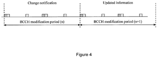
- Text Box 2 5.2.1.3 System information validity and notification of changes Change of system information (other than for ETWS and CMAS) only occurs at specific radio frames, i.e. the concept of a modification period is used.
- System information may be transmitted a number of times with the same content within a modification period, as defined by its scheduling.
- the modification period is configured by system information.
- the network changes (some of the) system information, it first notifies the UEs about this change, i.e. this may be done throughout a modification period. In the next modification period, the network transmits the updated system information.
- Figure 4 In which different types of shading indicate different system information.
- the UE Upon receiving a change notification, the UE acquires the new system information immediately from the start of the next modification period. The UE applies the previously acquired system information until the UE acquires the new system information.
- the Paging message is used to inform UEs in RRC_IDLE and UEs in RRC_CONNECTED about a system information change. If the UE receives a Paging message including the systemInfoModification , it knows that the system information will change at the next modification period boundary. Although the UE may be informed about changes in system information, no further details are provided e.g. regarding which system information will change.
- SystemInformationBlockType1 includes a value tag, systemInfoValueTag, that indicates if a change has occurred in the SI messages. UEs may use systemInfo ValueTag, e.g. upon return from out of coverage, to verify if the previously stored SI messages are still valid.
- E-UTRAN may not update systemInfoValueTag upon change of some system information e.g. ETWS information, CMAS information, regularly changing parameters like CDMA2000 system time (see 6.3). Similarly, E-UTRAN may not include the systemInfoModification within the Paging message upon change of some system information.
- the UE verifies that stored system information remains valid by either checking systemInfoValueTag in SystemInformationBlockType1 after the modification period boundary, or attempting to find the systemInfoModification indication at least modificationPeriodCoeff times during the modification period in case no paging is received, in every modification period.
- ETWS and/or CMAS capable UEs in RRC_CONNECTED shall attempt to read paging at least once every defaultPagingCycle to check whether ETWS and/or CMAS notification is present or not.
- the Paging message is used to inform ETWS capable UEs in RRC_IDLE and UEs in RRC_ CONNECTED about presence of an ETWS primary notification and/ or ETWS secondary notification. If the UE receives a Paging message including the etws-Indication, it shall start receiving the ETWS primary notification and/ or ETWS secondary notification according to schedulingInfoList contained in SystemInformationBlockType1. ⁇ Text omitted> 5.2.1.5 Indication of CMAS notification CMAS notification can occur at any point in time.
- the Paging message is used to inform CMAS capable UEs in RRC_IDLE and UEs in RRC_CONNECTED about presence of one or more CMAS notifications.
- the UE shall start receiving the CMAS notifications according to schedulingInfoList contained in SystemInfonnationBlockType1. ⁇ Text omitted> Text Box 5 5.5 PCH reception
- the UE shall: - if a PCH assignment has been received on the PDCCH of the PCell for the P-RNTI: - attempt to decode the TB on the PCH as indicated by the PDCCH information. - if a TB on the PCH has been successfully decoded: - deliver the decoded MAC PDU to upper layers.
- the UE may be configured by RRC with a DRX functionality that controls the UE's PDCCH monitoring activity for the UE's C-RNTI, TPC-PUCCH-RNTI, TPC-PUSCH-RNTI and Semi-Persistent Scheduling C-RNTI (if configured).
- RRC_CONNECTED if DRX is configured, the UE is allowed to monitor the PDCCH discontinuously using the DRX operation specified in this subclause; otherwise the UE monitors the PDCCH continuously.
- the UE shall also monitor PDCCH according to requirements found in other subclauses of this specification.
- RRC controls DRX operation by configuring the timers onDurationTimer, drx-InactivityTimer, drx-RetransmissionTimer (one per DL HARQ process except for the broadcast process), the longDRX-Cycle, the value of the drxStartOffset and optionally the drxShortCycleTimer and shortDRX-Cycle.
- a HARQ RTT timer per DL HARQ process (except for the broadcast process) is also defined (see subclause 7.7).
- the Active Time includes the time while: - onDurationTimer or drx-InactivityTimer or drx-RetransmissionTimer or mac-ContentionResolutionTimer (as described in subclause 5.1.5) is running; or - a Scheduling Request is sent on PUCCH and is pending (as described in subclause 5.4.4); or - an uplink grant for a pending HARQ retransmission can occur and there is data in the corresponding HARQ buffer; or - a PDCCH indicating a new transmission addressed to the C-RNTI of the UE has not been received after successful reception of a Random Access Response for the preamble not selected by the UE (as described in subclause 5.1.4).
- the UE When DRX is configured, the UE shall for each subframe: - if a HARQ RTT Timer expires in this subframe and the data in the soft buffer of the corresponding HARQ process was not successfully decoded: - start the drx-RetransmissionTimer for the corresponding HARQ process. - if a DRX Command MAC control element is received: - stop onDurationTimer, - stop drx-InactivityTimer.
- drx-InactivityTimer expires or a DRX Command MAC control element is received in this subframe: - if the Short DRX cycle is configured: - start or restart drxShortCycleTimer; - use the Short DRX Cycle. - else: - use the Long DRX cycle. - if drxShortCycleTimer expires in this subframe: - use the Long DRX cycle.
- a PDCCH-subframe if the subframe is not required for uplink transmission for half-duplex FDD UE operation and if the subframe is not part of a configured measurement gap: - monitor the PDCCH; - if the PDCCH indicates a DL transmission or if a DL assignment has been configured for this subframe: - start the HARQ RTT Timer for the corresponding HARQ process; - stop the drx-RetransmissionTimer for the corresponding HARQ process. - if the PDCCH indicates a new transmission (DL or UL): - start or restart drx-InactivityTimer.
- CQI masking (cqi-Mask) is setup by upper layers: - when onDurationTimer is not running, CQI/PMI/RI/PTI on PUCCH shall not be reported. - else: - when not in Active Time, CQI/PMI/RI/PTI on PUCCH shall not be reported. Regardless of whether the UE is monitoring PDCCH or not, the UE receives and transmits HARQ feedback and transmits type-1 -triggered SRS [2] when such is expected.
- a UE may optionally choose to not send CQI/PMI/RI/PTI reports on PUCCH and/or type-0-triggered SRS transmissions for up to 4 subframes following a PDCCH indicating a new transmission (UL or DL) received in the last subframe of active time.
- the choice not to send CQI/PMI/RI/PTI reports on PUCCH and/or type-0-triggered SRS transmissions is not applicable for subframes where onDurationTimer is running.
- the same active time applies to all activated serving cell(s).
Description
- As telecommunications technology has evolved, more advanced network access equipment has been introduced that can provide services that were not possible previously. This network access equipment might include systems and devices that are improvements of the equivalent equipment in a traditional wireless telecommunications system. Such advanced network access equipment may be included in evolving wireless communications standards, such as long-term evolution (LTE). For example, in an LTE system the advanced network access equipment might include an Evolved Universal Terrestrial Radio Access Network (E-UTRAN) node B (eNB). In various wireless communications systems, the advanced network access equipment may include a base station a wireless access point, or a similar component operable as an access node according to a corresponding wireless communications standard. Any such component will be referred to herein as an eNB, but it should be understood that such a component is not necessarily an eNB. Such a component may also be referred to herein as an access node or base station.
- LTE may be said to correspond to Third Generation Partnership Project (3GPP) Release 8 (Rel-8 or R8), Release 9 (Rel-9 or R9), and Release 10 (Rel-10 or R10), and possibly also to releases beyond Release 10, while LTE Advanced (LTE-A) may be said to correspond to Release 10 and possibly also to releases beyond Release 10. While the present disclosure is described in relation to an LTE-A system, the concepts are equally applicable to other wireless communications systems as well.
- As used herein, the term "user equipment" (alternatively "UE") refers to equipment that communicates with an access node to obtain services via the wireless communications system. A UE might in some cases refer to mobile devices such as mobile telephones, personal digital assistants, handheld or laptop computers, and similar devices that have telecommunications capabilities. Such a UE might include a device and its associated removable memory module, such as but not limited to a Universal Integrated Circuit Card (UICC) that includes a Subscriber Identity Module (SIM) application, a Universal Subscriber Identity Module (USIM) application, or a Removable User Identity Module (R-UIM) application. Alternatively, such a UE might include the device itself without such a module. In other cases, the term "UE" might refer to devices that have similar capabilities but that are not transportable, such as desktop computers, set-top boxes, or network appliances. The term "UE" can also refer to any hardware or software component that can terminate a communication session for a user. Also, the terms "user equipment," "UE," "user agent," "UA," "user device," and "mobile device" might be used synonymously herein.
- For a more complete understanding of this disclosure, reference is now made to the following brief description, taken in connection with the accompanying drawings and detailed description, wherein like reference numerals represent substantially similar parts.
-
Figure 1 is a diagram of a closed subscriber group HetNet deployment. -
Figure 2 is a diagram of a pico HetNet deployment. -
Figure 3 is a diagram of examples of almost blank subframes. -
Figure 4 is a diagram of notification of changes in system information. -
Figures 5a, 5b, and 5c are diagrams of paging occasions, the nB parameter, and a restricted subframe, according to an embodiment of the disclosure. -
Figure 6 is a table showing on-duration periods and paging occasions, according to an embodiment of the disclosure. -
Figure 7 is a table showing paging occasions and DRX on-durations that fit into restricted subframes, according to an embodiment of the disclosure. -
Figure 8 is a simplified block diagram of an exemplary network element according to one embodiment. -
Figure 9 is a block diagram with an example user equipment capable of being used with the systems and methods in the embodiments described herein. -
Figure 10 illustrates a processor and related components suitable for implementing the several embodiments of the present disclosure. - In wireless telecommunications systems, transmission equipment in an access node transmits signals throughout a geographical region referred to as a cell. One type of access node, such as an eNB, may be associated with a macro cell. Another type of access node, such as a low power node (e.g., femto cells, relays, or pico cells), may be associated with a low power cell. A heterogeneous network (HetNet) is a network that can include macro cells and low-power cells. For example, a HetNet may include a system of macro cells that operate at high power levels, and a system of low power cells, such as pico cells and relay nodes, which operate at reduced power levels. The low power cells can be overlaid on top of the macro cells, possibly sharing the same frequency. The low power cells may be used to offload the macro cells, improve coverage, and/or increase network performance. 3GPP has studied HetNet deployments as a performance enhancement enabler in LTE-Advanced (Release 10). In HetNet deployments, inter-cell interference coordination (ICIC) can prevent interference between the signals transmitted by the macro cell and the low-power nodes. Time domain-based resource sharing or coordination has been adopted as enhanced ICIC (eICIC). As described in 3GPP Technical Specification (TS) 36.300, the deployment scenarios where elCIC is utilized may include a closed subscriber group (CSG) (also referred to as femto cell) scenario and a pico cell scenario.
- In the CSG scenario, a dominant interference condition may occur when non-member users are in close proximity to a CSG cell. Typically, the Physical Downlink Control Channel (PDCCH) might be severely interfered with by downlink transmissions from a non-member CSG cell. Interference to the PDCCH of the macro cell can have a detrimental impact on both uplink and downlink data transfer between the UE and the macro cell. In addition, other downlink control channels and reference signals, from both the macro cell and the neighbor cells, that may be used for cell measurements and radio link monitoring can also be interfered with by a downlink transmission from a non-member CSG cell. Depending on network deployment and strategy, it may not be possible to divert the users suffering from inter-cell interference to another E-UTRA (Evolved UMTS (Universal Mobile Telecommunications System) Terrestrial Radio Access) carrier or another radio access technology (RAT). Time domain ICIC may be used to allow such non-member UEs to remain served by the macro cell on the same frequency layer. Such interference may be mitigated by the CSG cell utilizing Almost Blank Subframes (ABSs) to protect the corresponding macro cell's subframes from the interference. ABSs are subframes with reduced transmit power and/or reduced activity (possibly including no transmission) on some physical channels. A non-member UE may be signaled to utilize the protected resources for radio resource management (RRM) measurements, radio link monitoring (RLM) and channel state information (CSI) measurements for the serving macro cell, allowing the UE to continue to be served by the macro cell under strong interference from the CSG cell.
- An example of the CSG scenario is shown in
Figure 1 . Since a UE 110 that is not a member of a CSG is within the coverage area of theCSG cell 120, signals from theCSG cell 120 could interfere with signals sent to theUE 110 from amacro cell 130. - In the pico scenario, time domain ICIC may be utilized for pico users that are served in the edge of the serving pico cell, e.g., for traffic off-loading from a macro cell to a pico cell. Typically, the PDCCH might be severely interfered with by downlink transmission from the macro cell. In addition, other downlink control channels and reference signals, from both the pico cell and neighbor pico cells, that may be used for cell measurements and radio link monitoring can also be interfered with by a downlink transmission from the macro cell. Time domain ICIC may be utilized to allow such UEs to remain served by the pico cell on the same frequency layer. Such interference may be mitigated by the macro cell utilizing ABSs to protect the corresponding pico cell's subframes from the interference. A UE served by a pico cell can use the protected resources for RRM, RLM, and CSI measurements for the serving pico cell.
- An example of the pico scenario is shown in
Figure 2 . A UE 210 that is at the edge of the coverage area of apico cell 220 might be close enough to amacro cell 230 that signals from themacro cell 230 could interfere with signals sent to theUE 110 from thepico cell 220. - For time domain ICIC, subframe utilization across different cells can be coordinated in time through backhaul signaling or configuration of patterns in the ABS. The ABSs in an aggressor cell can be used to protect resources in subframes in a victim cell receiving strong inter-cell interference. The ABS pattern is used to identify subframes (referred to as "restricted" subframes or "protected" subframes) during which the aggressor cell transmits an almost blank subframe. The restricted subframes provide an opportunity to measure transmissions from the victim cell more accurately because there should be less or no interference from the aggressor cell.
- The serving eNB can ensure backwards compatibility toward UEs by transmitting necessary control channels and physical signals as well as system information during the restricted subframes. Patterns based on ABSs can be signaled to the UE to cause the UE to restrict measurements to specific subframes. These restrictions may be time domain measurement resource restrictions. There are different patterns depending on the type of measured cell (serving or neighbor cell) and measurement type (e.g., RRM or RLM).
- An example of an ABS pattern for the pico scenario is shown in
Figure 3 . In this example, a macro eNB 310 (the aggressor) configures and transfers the ABS patterns to a pico eNB 320 (the victim). To protect the UEs served by thepico eNB 320 in the edge of the pico cell, themacro eNB 310 does not schedule data transmissions in ABS subframes. Thepico eNB 320 may rely upon the ABS pattern to schedule transmissions to various UEs in the restricted subframes. For example, thepico eNB 320 may schedule transmissions to and from a first UE regardless of the ABS patterns, such as when the first UE is in the cell center. Alternatively, thepico eNB 320 may schedule transmissions to and from a second UE only in the restricted subframes indicated by the ABS pattern, such as when the second UE is near the cell edge. - In other words, the
pico layer subframes 330 that occur at substantially the same time as themacro layer subframes 340 may be said to be aligned with thosemacro layer subframes 340. Insubframes 340 where themacro eNB 310 is active, thepico eNB 320, insubframes 330, schedules only those UEs without excessive range extension. Duringpico layer subframes 350 that are aligned with almost blank macroeNB subframes 360, thepico eNB 320 can also schedule UEs that have large range extension offsets and that would otherwise not be schedulable due to too much interference from themacro layer 310. - The pico cell eNB may configure a UE at the edge of the cell with three different measurement resource restrictions independently based on an ABS pattern received from the macro cell eNB. The first restriction is for RRM measurement and RLM for the Primary cell, that is, PCell (in this case the serving pico cell). If configured, the UE measures and performs RLM of the PCell only in the restricted subframes. The second restriction is for RRM measurement of neighbor cells on the primary frequency. If configured, the UE measures neighbor cells in the restricted subframes only. The restriction also contains target neighbor cells optionally. The third restriction is for channel state estimation of the PCell. If configured, the UE estimates CSI and CQI/PMI/RI in the restricted subframes only.
- The subframe pattern for the measurement restrictions in the RRC protocol in version 10.3.0 of 3GPP TS 36.331 is defined as shown in
Text Box 1 at the end of the Detailed Description section of this document. In frequency division duplexing (FDD), the pattern is repetition of 40 subframes and in TDD the pattern is repetition of 20, 60 and 70 subframes depending on the configuration. - Sections 5.2.1.3 to 5.2.1.5 of version 10.3.0 of the RRC specification (3GPP TS 36.331) explain how paging is used to notify the UE of a change in system information and/or the arrival of Earthquake and Tsunami Warning System (ETWS) messages or Commercial Mobile Alert Service (CMAS) messages. These sections of 3GPP TS 36.331 are reproduced as Text Box 2 at the end of the Detailed Description section of this document. When a change in system information occurs, the UE attempts to read at least modificationPeriodCoeff times during the modification period, and for ETWS and CMAS notification the UE attempts to read at least once every defaultPagingCycle.
- The paging frame and paging occasion are defined in sections 7.1 and 7.2 of version 10.3.0 of 3GPP TS 36.304. These sections are reproduced as
Text Box 3 at the end of the Detailed Description section of this document. The paging frame and paging occasion depend on the International Mobile Subscriber Identity (IMSI) of the UE. In idle mode, the UE monitors a specific paging occasion in a paging frame. If there is a paging message for the UE, the paging occasion will include a resource block assignment where the UE should receive the paging message. In idle mode, the UE should check at least one paging occasion per default paging cycle (or per discontinuous reception (DRX) cycle). - In connected mode, the UE may also receive paging messages for a system information change or for ETWS/CMAS notification. Since those notifications are common for all UEs, a UE may read paging messages in any available paging occasions. It should be noted that the density of the paging frames is dependent upon the parameter nB. The busier a network is, the more paging needs to occur, and the higher the value of nB will be. For example, as shown in
Figure 5a , if nB is set to T/4, everyfourth radio frame 510 contains apaging occasion 520. As shown inFigure 5b , if nB is set to 4T, everyradio frame 510 contains fourpaging occasions 520.Figure 5c depicts apaging occasion 520a that is aligned with a restrictedsubframe 530 and apaging occasion 520b that is not aligned with a restricted subframe. - Parameters related to paging are signaled by the RRC protocol as specified in version 10.3.0 of 3GPP TS 36.331 and as shown in
Text Box 4 at the end of the Detailed Description section of this document. PCCH Config contains the default paging cycle and nB. BCCH Config contains the modification period coefficient. - DRX operation in connected mode is defined in section 5.7 of version 10.3.0 of the Medium Access Control (MAC) specification, 3GPP TS 36.321. That section is reproduced as
Text Box 5 at the end of the Detailed Description section of this document. The UE monitors the PDCCH in active time including the on-duration period. The start of the on-duration period is determined by a DRX start offset and a DRX cycle length. The objective of the DRX start offset is to evenly distribute traffic to be handled over each subframe. It should be noted that the UE might need to monitor the PDCCH according to other requirements, such as the paging channel reception described in section 5.5 of 3GPP TS 36.321. - This disclosure is related to the alignment between paging occasions and DRX configuration. In connected mode, a UE is allowed to read paging in any paging occasions. The UE may take advantage of an on-duration period to monitor paging occasions in order to not affect the DRX and battery consumption of the UE. On the other hand, the UE is required to read paging at least once every defaultPagingCycle to check whether ETWS or CMAS notification is present or not. Therefore, the UE may have to wake up from DRX to meet this requirement.
- In order to ensure reliable paging detection in a HetNet environment, the UE may need to find a paging occasion that is in a restricted subframe. There may be a sufficient number of such occasions to satisfy the ETWS and CMAS monitoring requirement if the UE is allowed to wake up from the DRX to read paging. From UE battery life perspectives, waking up from DRX should be avoided as much as possible. The embodiments disclosed herein provide for first checking if it is possible to limit access to the paging channel only during on-duration periods that are protected by restricted subframes while meeting the ETWS and CMAS monitoring requirement.
-
Figure 6 shows the starting subframe of on-duration periods, the nearest and second nearest paging occasions from the on-duration periods, and the corresponding 1/8 subframe pattern which covers each of the first subframe of the on-duration periods and the two paging occasions. InFigure 6 , long DRX cycle, DRX Start offset, on-duration period and nB in PCCH configuration are set to 256 (28) ms, 1 subframe, 4 subframes, and same as the default paging cycle, respectively. A 1/8 subframe pattern is distinguished by the position of a restricted subframe which is an integer 0 to 7. - The paging occasions which are both in an on-duration period and are protected by the restricted subframes of the
pattern 1 are highlighted with darker shading. The interval between the adjacent darkly shaded subframes is 1280 ms. If the default paging cycle is set to 640 ms, reading just the darker shaded frames does not meet the ETWS and CMAS monitoring requirement. If the default paging cycle is set to 1280 ms, the requirement is met. However, if the UE fails to decode once, then the UE may need to wake up from the DRX and read another paging occasion. It can thus be observed that, with a certain combination of PCCH configuration, DRX configuration, and subframe pattern, the ETWS and CMAS monitoring requirement is not met if the UE is limited to reading paging occasions only in on-duration periods that are in restricted subframes. - If the ETWS and CMAS monitoring requirement is not satisfied, the UE may need to wake up and read more paging occasions that are protected by the subframe pattern. From the perspective of UE battery saving, the frequency of such wake-ups should be kept to a minimum.
- Subframes highlighted with lighter shading in
Figure 6 are paging occasions protected by thesame subframe pattern 1 and near the on-duration period. For example, thesubframe 1289 is just five subframes after the end of the on-duration period (subframe 1281 - 1284). If any new data arrives during the on-duration period, thesubframe 1289 will be in active time due to the inactivity timer, and the UE can read the paging occasion during the active time. Thesubframe 1809 is 16 subframes after thesubframe 1793. If there is a downlink assignment insubframe 1793 and the decoding of the assignment fails two times, thesubframe 1809 will be in active time waiting for retransmission. - The intervals between the
subframes - In the above UE-based embodiment, the UE may need to estimate how many paging occasions would be in restricted subframes and in active time during the next default paging cycles. The UE could maintain and use the average length of the active time for the estimation. However, the estimation may not be perfect since the active time depends on data arrival in the future.
- In an alternative embodiment, a specific configuration of DRX parameters may be implemented to alleviate the problem. For example, by setting the long DRX cycle length to 320 (5 * 26) ms and the DRX start offset to 9, every on-duration period coincides with a paging occasion that is protected by a restricted subframe, as shown in Table 1 below. In this case, the interval between the two paging occasions to read is 320 ms, which meets the ETWS and CMAS monitoring requirement (with a default paging cycle of 640 ms). With a specific setting of DRX configuration (long DRX cycle length set to 5*2n and DRX start offset to align on-duration periods to paging occasions that are protected by restricted subframes), the UE may be able to avoid extra wake-up from the DRX and implement estimation of active time duration. Therefore, in an embodiment, the network may configure the long DRX cycle to 5*2n and the DRX start offset to align on-duration periods to paging occasions that are protected by restricted subframes in a PCell.
Table 1 On Duration and PO position of restricted SF 9 1 329 1 649 1 969 1 1289 1 1609 1 - Long DRX cycle length can be configured to 10, 20, 32, 40, 64, 80,128, 160, 256, 320, 512, 640, 1024, 1280, 2048, 2560 subframes according to the RRC specification (3GPP TS 36.331 version 10.3.0).
Figure 7 shows the start of on-duration periods (OnD) in subframes and the paging occasions closest to the on-duration period (Closest PO) in subframes when the long DRX cycle length is 1024 subframes and its start offset is 19 subframes. Assuming that the subframe pattern is RSFP 3 ("0001000000010000..."), all the first subframes of on-duration periods fit into the restricted subframes, but not all the paging occasions fit into the restricted subframes. The interval between the paging occasions that fit into on-duration periods and the restricted subframes is 5120 subframes (512 radio frames), as highlighted with darker shading. Paging occasions that fit into the restricted subframes and are closest to the on-duration period (assuming the on-duration is four subframes) are highlighted with lighter shading. Since the active time may be extended over the on-duration period by retransmission or a new data arrival and the inactivity timer, there is a good chance that paging occasions highlighted with lighter shading may be in the active time because only five subframes are extended after the end of on-duration period. The shortest interval between the darkly and lightly shaded subframes is only 2040 subframes. - If the UE is limited to read paging during the on-duration period that fits into restricted subframes only, the interval between the paging occasions may be too long. As described above, for detection of ETWS and CMAS notification, the UE needs to read paging at least once per default paging cycle, which could be configured to be 256 radio frames. If the UE attempts to read paging in an active time that fits into the restricted subframes, the above requirement can be satisfied.
- In summary, UE behavior is currently not clear with regard to paging reception in connected mode in HetNet environments. If the UE is limited to read paging in on-duration periods which fit into the restricted subframes only, the UE may not be able to read paging as often as required for system information changes or ETWS/CMAS notifications. The implementations described herein address this problem.
- When DRX is not configured, the UE reads paging in paging occasions which fit into protected subframes. There could be many paging occasions that satisfy the condition above to meet the requirements for system information changes and ETWS/CMAS notifications. For example, when DRX is configured, in a first behavior, the UE may read paging when the paging occasion fits into protected subframes. Alternatively, in a second behavior, the UE may read paging when the paging occasion is within the active time. Alternatively, in a third behavior, the UE may read paging when the paging occasion is within the active time and fits into protected subframes. Alternatively, in a fourth behavior, the UE may read paging when the paging occasion is within an on-duration or when the inactivity timer is running and the paging occasion fits into protected subframes. Alternatively, in a fifth behavior, the UE may read paging when the paging occasion is within an on-duration and the paging occasion fits into protected subframes.
- With the first behavior, the UE may have sufficient opportunities to read paging, but the UE may need to wake up from the DRX when the DRX is not aligned. As for the second behavior, the UE may have sufficient opportunities to read paging, but some of the paging occasions are not restricted subframes. Therefore, the UE's battery power may be wasted when the UE encounters many decoding failures. With regard to the fifth behavior, the battery usage could be improved. However, as indicated above, the paging occasions to read in the fifth behavior may be fewer than the ETWS/CMAS monitoring requirement.
- The third and fourth behaviors described above may be used in order to satisfy the paging requirements and provide efficient battery usage. That is, the UE might read paging when the paging occasion is within protected subframes and in active time. It should be understood that other combinations of the behaviors described may be feasible in accordance with various embodiments of this disclosure.
- For the third and fourth behaviors, the UE may estimate available paging occasions which satisfy the requirements described above during the modification period or default paging cycle based on the BCCH and PCCH configurations and the configured DRX and subframe patterns. In order to calculate the number of paging occasions to read, the UE may assume that the probability of a target paging occasion being within the active time is a predetermined number, for example 50%. Alternatively, the UE may assume that the probability of a target paging occasion being within the active time is proportional to current data activity (for example, the average number of new transmissions (i.e., triggering the inactivity timer) per on-duration time). For example, if the average ratio of new transmission arrivals in an on-duration (4 subframes) is 25% and the inactivity timer is 20 subframes, the calculated active time is 4*(1-0.25)+(20+4/2)*0.25 = 9. Applying this number to the table in Figure 11, the paging occasions highlighted with lighter shading can be read while the UE is in active mode. Alternatively, the UE may calculate the average length of the active time in subframes and use the average to estimate the number of paging occasions to read.
- As described above, the number of paging occasions to read should typically be higher than or equal to one occasion within the default paging cycle for ETWS/CMAS notification and higher than modificationperiodcoeff times within the modification period for a system information change notification. Based on the estimation of how many paging occasions to read, the UE may choose which behavior to use in reading paging. In terms of battery usage, the fifth behavior may be preferred because the UE does not need to wake up just to read paging. However, depending on the PCCH, DRX and subframe pattern configuration, the estimated number may be less than the requirement. In such a case, the UE may choose to use the third or fourth behavior. If the estimated number is still not sufficient, the UE may be configured to operate according to the first or second behavior.
- Alternatively, with a careful choice of DRX configuration parameters, paging occasions can coincide with on-duration periods and restricted subframes. For example, in FDD, assuming nB is set to T, if the long DRX cycle in connected mode DRX configuration is set to 5*2n (n = 3, 4, ... 9), and the DRX start offset is set to 10*m+9 (m = 0, 1, ... floor((5*2n - 9)/10), some paging occasions are in an on-duration and in a restricted subframe. Table 2 below shows an example when n is 7 and m is 10. As seen in the table, every on-duration period coincides with a paging occasion and a restricted subframe. As long as the DRX long cycle is shorter than or equal to the default paging cycle, the UE does not have to wake up from the DRX. In order to be applicable to more general cases for FDD, the condition above can be extended as follows. Long DRX cycle in connected mode DRX configuration is set to 5*2n (n = 3, 4, ... 9). DRX start offset is set to 10 * max (1, T/nB) * m + s - d, where T and nB are defined in
section 7 of 3GPP TS 36.304, m is an integer (0 <= m < ceiling((5*2n - s)/(10*max(1, T/nB))), d is an integer (0 <= d < on duration period in subframe) and s is the subframe number of a paging occasion in one radio frame. For example, if nB <=T, s is 9, if nB = 2T s is 4 or 9 and if nB = 4T s is 0, 4, 5, or 9. Concerning time division duplexing (TDD), a typical subframe pattern is 1/10. The condition is Long DRX cycle in connected mode DRX configuration is set to 5*2n (n = 1,2, ... 9). DRX start offset is set to 10 * max (1, T/nB) * m + s - d, where T and nB are defined insection 7 of 3GPP TS 36.304, m is an integer (0 <= m < ceiling((5*2n - s)/(10*max(1, T/nB))), d is 0 or 1 and s is the subframe number of a paging occasion in one radio frame. For example, if nB <=T, s is 0, if nB = 2T s is 0 or 5 and if nB = 4T s is 0, 1, 5, or 6.Table 2 On Duration start in SF RSFP of On duration start PO nearest to on duration RSFP of the PO 109 5 109 5 749 5 749 5 1389 5 1389 5 2029 5 2029 5 2669 5 2669 5 3309 5 3309 5 - The concepts described above can be implemented by changes to the current MAC specification (3GPP TS 36.321) as shown in an embodiment of the disclosure below.
- When the UE needs to receive PCH, the UE shall:
- if a PCH assignment has been received on the PDCCH of the PCell for the P-RNTI:
- attempt to decode the TB on the PCH as indicated by the PDCCH information.
- if a TB on the PCH has been successfully decoded:
- deliver the decoded MAC PDU to upper layers.
- NOTE: The UE should attempt to read paging in active time and restricted subframes when measSubframePatternPCell is configured
- Alternatively, additional description with regard to DRX configuration can be added to the ASN.1 definition as shown in an embodiment of the disclosure below.
MAC-MainConfig field descriptions <text omitted> longDRX-CycleStartOffset longDRX-Cycle and drxStartOffset in TS 36.321 [6]. The value of longDRX-Cycle is in number of sub-frames. Value sf10 corresponds to 10 sub-frames, sf20 corresponds to 20 sub-frames and so on. If shortDRX-Cycle is configured, the value of longDRX-Cycle shall be a multiple of the shortDRX-Cycle value. The value of drxStartOffset value is in number of sub-frames. When ABS subframes are used in a victim cell, longDRX-Cycle is set to 5*2n where n is 3,4...9 in FDD and 1,2,..9 forTDD. drxStartOffset should be adjusted so that some paging occasions are in an on duration period and in a restricted subframe. - As described herein, in one embodiment the UE may be configured to check paging occasions based on subframes where the paging occasion would be aligned with the restricted subframe pattern. In another embodiment, the network may utilize the DRX configuration such that the on-duration of DRX and the restricted subframe pattern are aligned with paging occasions.
- The concepts described above may be implemented by a network element. A simplified network element is shown with regard to
Figure 8 . InFigure 8 ,network element 3110 includes aprocessor 3120 and acommunications subsystem 3130, where theprocessor 3120 andcommunications subsystem 3130 cooperate to perform the methods described above. - Further, the above may be implemented by a UE. One exemplary device is described below with regard to
Figure 9 .UE 3200 is typically a two-way wireless communication device having voice and data communication capabilities.UE 3200 generally has the capability to communicate with other computer systems on the Internet. Depending on the exact functionality provided, the UE may be referred to as a data messaging device, a two-way pager, a wireless e-mail device, a cellular telephone with data messaging capabilities, a wireless Internet appliance, a wireless device, a mobile device, or a data communication device, as examples. - Where
UE 3200 is enabled for two-way communication, it may incorporate acommunication subsystem 3211, including areceiver 3212 and atransmitter 3214, as well as associated components such as one ormore antenna elements communication subsystem 3211 will be dependent upon the communication network in which the device is intended to operate. - Network access requirements will also vary depending upon the type of
network 3219. In some networks network access is associated with a subscriber or user ofUE 3200. A UE may require a removable user identity module (RUIM) or a subscriber identity module (SIM) card in order to operate on a network. The SIM/RUIM interface 3244 is normally similar to a card-slot into which a SIM/RUIM card can be inserted and ejected. The SIM/RUIM card can have memory and hold manykey configurations 3251, andother information 3253 such as identification, and subscriber related information. - When required network registration or activation procedures have been completed,
UE 3200 may send and receive communication signals over thenetwork 3219. As illustrated inFigure 9 ,network 3219 can consist of multiple base stations communicating with the UE. - Signals received by
antenna 3216 throughcommunication network 3219 are input toreceiver 3212, which may perform such common receiver functions as signal amplification, frequency down conversion, filtering, channel selection and the like. Analog to digital (A/D) conversion of a received signal allows more complex communication functions such as demodulation and decoding to be performed in theDSP 3220. In a similar manner, signals to be transmitted are processed, including modulation and encoding for example, byDSP 3220 and input totransmitter 3214 for digital to analog (D/A) conversion, frequency up conversion, filtering, amplification and transmission over thecommunication network 3219 viaantenna 3218.DSP 3220 not only processes communication signals, but also provides for receiver and transmitter control. For example, the gains applied to communication signals inreceiver 3212 andtransmitter 3214 may be adaptively controlled through automatic gain control algorithms implemented inDSP 3220. -
UE 3200 generally includes aprocessor 3238 which controls the overall operation of the device. Communication functions, including data and voice communications, are performed throughcommunication subsystem 3211.Processor 3238 also interacts with further device subsystems such as thedisplay 3222, flash memory 3224, random access memory (RAM) 3226, auxiliary input/output (I/O)subsystems 3228,serial port 3230, one or more keyboards orkeypads 3232,speaker 3234,microphone 3236,other communication subsystem 3240 such as a short-range communications subsystem and any other device subsystems generally designated as 3242.Serial port 3230 could include a USB port or other port known to those in the art. - Some of the subsystems shown in
Figure 9 perform communication-related functions, whereas other subsystems may provide "resident" or on-device functions. Notably, some subsystems, such askeyboard 3232 anddisplay 3222, for example, may be used for both communication-related functions, such as entering a text message for transmission over a communication network, and device-resident functions such as a calculator or task list. - Operating system software used by the
processor 3238 may be stored in a persistent store such as flash memory 3224, which may instead be a read-only memory (ROM) or similar storage element (not shown). Those skilled in the art will appreciate that the operating system, specific device applications, or parts thereof, may be temporarily loaded into a volatile memory such asRAM 3226. Received communication signals may also be stored inRAM 3226. - As shown, flash memory 3224 can be segregated into different areas for both
computer programs 3258 andprogram data storage Processor 3238, in addition to its operating system functions, may enable execution of software applications on the UE. A predetermined set of applications that control basic operations, including at least data and voice communication applications for example, will normally be installed onUE 3200 during manufacturing. Other applications could be installed subsequently or dynamically. - Applications and software may be stored on any computer readable storage medium. The computer readable storage medium may be a tangible or in transitory/non-transitory medium such as optical (e.g., CD, DVD, etc.), magnetic (e.g., tape) or other memory known in the art.
- One software application may be a personal information manager (PIM) application having the ability to organize and manage data items relating to the user of the UE such as, but not limited to, e-mail, calendar events, voice mails, appointments, and task items. Naturally, one or more memory stores may be available on the UE to facilitate storage of PIM data items. Such PIM application may have the ability to send and receive data items, via the
wireless network 3219. Further applications may also be loaded onto theUE 3200 through thenetwork 3219, an auxiliary I/O subsystem 3228,serial port 3230, short-range communications subsystem 3240 or any othersuitable subsystem 3242, and installed by a user in theRAM 3226 or a non-volatile store (not shown) for execution by theprocessor 3238. Such flexibility in application installation increases the functionality of the device and may provide enhanced on-device functions, communication-related functions, or both. For example, secure communication applications may enable electronic commerce functions and other such financial transactions to be performed using theUE 3200. - In a data communication mode, a received signal such as a text message or web page download will be processed by the
communication subsystem 3211 and input to theprocessor 3238, which may further process the received signal for output to thedisplay 3222, or alternatively to an auxiliary I/O device 3228. - A user of
UE 3200 may also compose data items such as email messages for example, using thekeyboard 3232, which may be a complete alphanumeric keyboard or telephone-type keypad, among others, in conjunction with thedisplay 3222 and possibly an auxiliary I/O device 3228. Such composed items may then be transmitted over a communication network through thecommunication subsystem 3211. - For voice communications, overall operation of
UE 3200 is similar, except that received signals may typically be output to aspeaker 3234 and signals for transmission may be generated by amicrophone 3236. Alternative voice or audio I/O subsystems, such as a voice message recording subsystem, may also be implemented onUE 3200. Although voice or audio signal output is preferably accomplished primarily through thespeaker 3234,display 3222 may also be used to provide an indication of the identity of a calling party, the duration of a voice call, or other voice call related information for example. -
Serial port 3230 inFigure 9 may normally be implemented in a personal digital assistant (PDA)-type UE for which synchronization with a user's desktop computer (not shown) may be desirable, but is an optional device component. Such aport 3230 may enable a user to set preferences through an external device or software application and may extend the capabilities ofUE 3200 by providing for information or software downloads toUE 3200 other than through a wireless communication network. The alternate download path may for example be used to load an encryption key onto the device through a direct and thus reliable and trusted connection to thereby enable secure device communication. As will be appreciated by those skilled in the art,serial port 3230 can further be used to connect the UE to a computer to act as a modem. -
Other communications subsystems 3240, such as a short-range communications subsystem, is a further optional component which may provide for communication betweenUE 3200 and different systems or devices, which need not necessarily be similar devices. For example, thesubsystem 3240 may include an infrared device and associated circuits and components or a Bluetooth™ communication module to provide for communication with similarly enabled systems and devices.Subsystem 3240 may further include non-cellular communications such as WiFi or WiMax. - The UE and other components described above might include a processing component that is capable of executing instructions related to the actions described above.
Figure 10 illustrates an example of asystem 3300 that includes aprocessing component 3310 suitable for implementing one or more embodiments disclosed herein. Theprocessing component 3310 may be substantially similar to theprocessor 3120 ofFigure 8 and/or theprocessor 3238 ofFigure 9 . - In addition to the processor 3310 (which may be referred to as a central processor unit or CPU), the
system 3300 might includenetwork connectivity devices 3320, random access memory (RAM) 3330, read only memory (ROM) 3340,secondary storage 3350, and input/output (I/O)devices 3360. These components might communicate with one another via abus 3370. In some cases, some of these components may not be present or may be combined in various combinations with one another or with other components not shown. These components might be located in a single physical entity or in more than one physical entity. Any actions described herein as being taken by theprocessor 3310 might be taken by theprocessor 3310 alone or by theprocessor 3310 in conjunction with one or more components shown or not shown in the drawing, such as a digital signal processor (DSP) 3380. Although theDSP 3380 is shown as a separate component, theDSP 3380 might be incorporated into theprocessor 3310. - The
processor 3310 executes instructions, codes, computer programs, or scripts that it might access from thenetwork connectivity devices 3320,RAM 3330,ROM 3340, or secondary storage 3350 (which might include various disk-based systems such as hard disk, floppy disk, or optical disk). While only oneCPU 3310 is shown, multiple processors may be present. Thus, while instructions may be discussed as being executed by a processor, the instructions may be executed simultaneously, serially, or otherwise by one or multiple processors. Theprocessor 3310 may be implemented as one or more CPU chips. - The
network connectivity devices 3320 may take the form of modems, modem banks, Ethernet devices, universal serial bus (USB) interface devices, serial interfaces, token ring devices, fiber distributed data interface (FDDI) devices, wireless local area network (WLAN) devices, radio transceiver devices such as code division multiple access (CDMA) devices, global system for mobile communications (GSM) radio transceiver devices, universal mobile telecommunications system (UMTS) radio transceiver devices, long term evolution (LTE) radio transceiver devices, worldwide interoperability for microwave access (WiMax) devices, and/or other well-known devices for connecting to networks. Thesenetwork connectivity devices 3320 may enable theprocessor 3310 to communicate with the Internet or one or more telecommunications networks or other networks from which theprocessor 3310 might receive information or to which theprocessor 3310 might output information. Thenetwork connectivity devices 3320 might also include one ormore transceiver components 3325 capable of transmitting and/or receiving data wirelessly. - The
RAM 3330 might be used to store volatile data and perhaps to store instructions that are executed by theprocessor 3310. TheROM 3340 is a non-volatile memory device that typically has a smaller memory capacity than the memory capacity of thesecondary storage 3350.ROM 3340 might be used to store instructions and perhaps data that are read during execution of the instructions. Access to bothRAM 3330 andROM 3340 is typically faster than tosecondary storage 3350. Thesecondary storage 3350 is typically comprised of one or more disk drives or tape drives and might be used for non-volatile storage of data or as an over-flow data storage device ifRAM 3330 is not large enough to hold all working data.Secondary storage 3350 may be used to store programs that are loaded intoRAM 3330 when such programs are selected for execution. - The I/
O devices 3360 may include liquid crystal displays (LCDs), touch screen displays, keyboards, keypads, switches, dials, mice, track balls, voice recognizers, card readers, paper tape readers, printers, video monitors, or other well-known input/output devices. Also, thetransceiver 3325 might be considered to be a component of the I/O devices 3360 instead of or in addition to being a component of thenetwork connectivity devices 3320. - The following are referred to for all purposes: 3GPP TS 36.213 version 10.3.0, 3GPP TS 36.300 version 10.5.0, 3GPP TS 36.304 version 10.3.0, 3GPP TS 36.321 version 10.3.0, and 3GPP TS 36.331 version 10.3.0.
- In an embodiment, a method for operating a UE in a wireless communications network is provided. The method comprises attempting, by a UE configured to operate in a DRX mode and with time domain measurement resource restrictions, to read a paging message in a paging occasion in a restricted subframe during DRX active time.
- The method may further comprise estimating, by the UE, available paging occasions based on paging control channel configurations and configured DRX parameters and restricted subframe patterns. The method may further comprise calculating, by the UE, the number of paging occasions to read by assuming that the probability of a target paging occasion being within the active time is a predetermined number. The method may further comprise calculating, by the UE, the number of paging occasions to read by assuming that the probability of a target paging occasion being within the active time is proportional to current data activity.
- In another embodiment, a UE is provided. The UE comprises a processor configured such that the UE attempts to read a paging message in a paging occasion in a restricted subframe during DRX active time. The UE is configured to operate in DRX mode and with time domain measurement resource restrictions.
- The UE may also estimate available paging occasions based on paging control channel configurations and configured DRX parameters and restricted subframe patterns. The UE may also calculates the number of paging occasions to read by assuming that the probability of a target paging occasion being within the active time is a predetermined number. The UE may also calculate the number of paging occasions to read by assuming that the probability of a target paging occasion being within the active time is proportional to current data activity.
- In another embodiment, a method for operating a network element in a wireless communications network is provided. The method comprises configuring, by the network element, a DRX cycle to 5*2n subframes and a DRX start offset that aligns on-duration periods to paging occasions that are protected by restricted subframes. The network element is configured to utilize DRX and time domain measurement resource restrictions.
- In such a method the DRX start offset may be set to 10*m+9 (m = 0, 1, ... floor((5*2n - 9)/10). The network element may be a victim node in a heterogeneous network. The victim node may be at least one of: a pico cell; a femto cell; a relay; or a macro cell.
- In another embodiment, a network element in a wireless communications network is provided. The network element comprises a processor configured such that the network element configures a DRX cycle to 5*2n subframes and a DRX start offset that aligns on-duration periods to paging occasions that are protected by restricted subframes. The network element is configured to utilize DRX and time domain measurement resource restrictions.
- In such a network element, the DRX start offset may be set to 10*m+9 (m = 0, 1, ... floor((5*2n - 9)/10). The network element may be a victim node in a heterogeneous network. The victim node may be at least one of: a pico cell; a femto cell; a relay; or a macro cell.
- In another embodiment, a method for operating a UE in a wireless heterogeneous network is provided. The method comprises attempting, by the UE, to read a paging radio network temporary identifier in selected subframes at a selected time interval. The method further comprises activating, by the UE, its receiver to receive transmissions from at least one of an underlay cell and an overlay cell during an active time. The subframes are selected by the network to promote intercell interference coordination via a coordination method, the coordination method being one of a backhaul signaling technique or an almost blank subframe technique.
- In such a method, the selected time interval duration may be one of a value allocated to the UE by the network or a broadcast value. Such method may further comprise receiving, by the UE, a configuration, wherein the configuration includes a DRX interval set to 5*2n subframes and a start offset that substantially results in the UE reading paging messages during the selected subframes and the UE not seeking to read paging messages in other subframes and within an on-duration, and wherein n is a positive integer
- The present disclosure provides illustrative implementations of one or more embodiments. The disclosure should in no way be limited to the illustrative implementations, drawings, and techniques illustrated below, including the exemplary designs and implementations illustrated and described herein, but may be modified within the scope of the appended claims.
- A person of skill in the relevant art will recognized that the disclosed systems and/or methods may be implemented using any number of techniques, whether currently known or in existence. Embodiments are described herein in the context of an LTE wireless network or system, but can be adapted for other wireless networks or systems.
- This written description may enable those skilled in the art to make and use embodiments having alternative elements that likewise correspond to the elements of the techniques of this application. The intended scope of the techniques of this application thus includes other structures, systems or methods that do not differ from the techniques of this application as described herein, and further includes other structures, systems or methods with insubstantial differences from the techniques of this application as described herein.
- While several embodiments have been provided in the present disclosure, it should be understood that the disclosed systems and methods may be embodied in many other specific forms without departing from the scope of the present disclosure. The present examples are to be considered as illustrative and not restrictive, and the intention is not to be limited to the details given herein. For example, the various elements or components may be combined or integrated in another system or certain features may be omitted, or not implemented.
- Also, techniques, systems, subsystems and methods described and illustrated in the various embodiments as discrete or separate may be combined or integrated with other systems, modules, techniques, or methods without departing from the scope of the present disclosure. Other items shown or discussed as coupled or directly coupled or communicating with each other may be indirectly coupled or communicating through some interface, device, or intermediate component, whether electrically, mechanically, or otherwise. Other examples of changes, substitutions, and alterations are ascertainable by one skilled in the art and could be made without departing from the scope disclosed herein.

Text Box 2 5.2.1.3 System information validity and notification of changes Change of system information (other than for ETWS and CMAS) only occurs at specific radio frames, i.e. the concept of a modification period is used. System information may be transmitted a number of times with the same content within a modification period, as defined by its scheduling. The modification period boundaries are defined by SFN values for which SFN mod m= 0, where m is the number of radio frames comprising the modification period. The modification period is configured by system information. When the network changes (some of the) system information, it first notifies the UEs about this change, i.e. this may be done throughout a modification period. In the next modification period, the network transmits the updated system information. These general principles are illustrated in Figure 4 , in which different types of shading indicate different system information. Upon receiving a change notification, the UE acquires the new system information immediately from the start of the next modification period. The UE applies the previously acquired system information until the UE acquires the new system information.The Paging message is used to inform UEs in RRC_IDLE and UEs in RRC_CONNECTED about a system information change. If the UE receives a Paging message including the systemInfoModification, it knows that the system information will change at the next modification period boundary. Although the UE may be informed about changes in system information, no further details are provided e.g. regarding which system information will change. SystemInformationBlockType1 includes a value tag, systemInfoValueTag, that indicates if a change has occurred in the SI messages. UEs may use systemInfo ValueTag, e.g. upon return from out of coverage, to verify if the previously stored SI messages are still valid. Additionally, the UE considers stored system information to be invalid after 3 hours from the moment it was successfully confirmed as valid, unless specified otherwise. E-UTRAN may not update systemInfoValueTag upon change of some system information e.g. ETWS information, CMAS information, regularly changing parameters like CDMA2000 system time (see 6.3). Similarly, E-UTRAN may not include the systemInfoModification within the Paging message upon change of some system information. The UE verifies that stored system information remains valid by either checking systemInfoValueTag in SystemInformationBlockType1 after the modification period boundary, or attempting to find the systemInfoModification indication at least modificationPeriodCoeff times during the modification period in case no paging is received, in every modification period. If no paging message is received by the UE during a modification period, the UE may assume that no change of system information will occur at the next modification period boundary. If UE in RRC_CONNECTED, during a modification period, receives one paging message, it may deduce from the presence/ absence of systemInfoModification whether a change of system information other than ETWS and CMAS information will occur in the next modification period or not. ETWS and/or CMAS capable UEs in RRC_CONNECTED shall attempt to read paging at least once every defaultPagingCycle to check whether ETWS and/or CMAS notification is present or not. 5.2.1.4 Indication of ETWS notification ETWS primary notification and/ or ETWS secondary notification can occur at any point in time. The Paging message is used to inform ETWS capable UEs in RRC_IDLE and UEs in RRC_ CONNECTED about presence of an ETWS primary notification and/ or ETWS secondary notification. If the UE receives a Paging message including the etws-Indication, it shall start receiving the ETWS primary notification and/ or ETWS secondary notification according to schedulingInfoList contained in SystemInformationBlockType1. <Text omitted> 5.2.1.5 Indication of CMAS notification CMAS notification can occur at any point in time. The Paging message is used to inform CMAS capable UEs in RRC_IDLE and UEs in RRC_CONNECTED about presence of one or more CMAS notifications. If the UE receives a Paging message including the cmas-Indication, it shall start receiving the CMAS notifications according to schedulingInfoList contained in SystemInfonnationBlockType1. <Text omitted> 


Text Box 55.5 PCH reception When the UE needs to receive PCH, the UE shall: - if a PCH assignment has been received on the PDCCH of the PCell for the P-RNTI: - attempt to decode the TB on the PCH as indicated by the PDCCH information. - if a TB on the PCH has been successfully decoded: - deliver the decoded MAC PDU to upper layers. <text omited> 5.7 Discontinuous Reception (DRX) The UE may be configured by RRC with a DRX functionality that controls the UE's PDCCH monitoring activity for the UE's C-RNTI, TPC-PUCCH-RNTI, TPC-PUSCH-RNTI and Semi-Persistent Scheduling C-RNTI (if configured). When in RRC_CONNECTED, if DRX is configured, the UE is allowed to monitor the PDCCH discontinuously using the DRX operation specified in this subclause; otherwise the UE monitors the PDCCH continuously. When using DRX operation, the UE shall also monitor PDCCH according to requirements found in other subclauses of this specification. RRC controls DRX operation by configuring the timers onDurationTimer, drx-InactivityTimer, drx-RetransmissionTimer (one per DL HARQ process except for the broadcast process), the longDRX-Cycle, the value of the drxStartOffset and optionally the drxShortCycleTimer and shortDRX-Cycle. A HARQ RTT timer per DL HARQ process (except for the broadcast process) is also defined (see subclause 7.7). When a DRX cycle is configured, the Active Time includes the time while: - onDurationTimer or drx-InactivityTimer or drx-RetransmissionTimer or mac-ContentionResolutionTimer (as described in subclause 5.1.5) is running; or - a Scheduling Request is sent on PUCCH and is pending (as described in subclause 5.4.4); or - an uplink grant for a pending HARQ retransmission can occur and there is data in the corresponding HARQ buffer; or - a PDCCH indicating a new transmission addressed to the C-RNTI of the UE has not been received after successful reception of a Random Access Response for the preamble not selected by the UE (as described in subclause 5.1.4). When DRX is configured, the UE shall for each subframe: - if a HARQ RTT Timer expires in this subframe and the data in the soft buffer of the corresponding HARQ process was not successfully decoded: - start the drx-RetransmissionTimer for the corresponding HARQ process. - if a DRX Command MAC control element is received: - stop onDurationTimer, - stop drx-InactivityTimer. - if drx-InactivityTimer expires or a DRX Command MAC control element is received in this subframe: - if the Short DRX cycle is configured: - start or restart drxShortCycleTimer; - use the Short DRX Cycle. - else: - use the Long DRX cycle. - if drxShortCycleTimer expires in this subframe: - use the Long DRX cycle. - If the Short DRX Cycle is used and [(SFN * 10) + subframe number] modulo (shortDRX-Cycle) = (drxStartOffset) modulo (shortDRX-Cycle); or - if the Long DRX Cycle is used and [(SFN * 10) + subframe number] modulo (longDRX-Cycle) = drxStartOffset: - start onDurationTimer. - during the Active Time, for a PDCCH-subframe, if the subframe is not required for uplink transmission for half-duplex FDD UE operation and if the subframe is not part of a configured measurement gap: - monitor the PDCCH; - if the PDCCH indicates a DL transmission or if a DL assignment has been configured for this subframe: - start the HARQ RTT Timer for the corresponding HARQ process; - stop the drx-RetransmissionTimer for the corresponding HARQ process. - if the PDCCH indicates a new transmission (DL or UL): - start or restart drx-InactivityTimer. - when not in Active Time, type-0-triggered SRS [2] shall not be reported. - if CQI masking (cqi-Mask) is setup by upper layers: - when onDurationTimer is not running, CQI/PMI/RI/PTI on PUCCH shall not be reported. - else: - when not in Active Time, CQI/PMI/RI/PTI on PUCCH shall not be reported. Regardless of whether the UE is monitoring PDCCH or not, the UE receives and transmits HARQ feedback and transmits type-1 -triggered SRS [2] when such is expected. NOTE: A UE may optionally choose to not send CQI/PMI/RI/PTI reports on PUCCH and/or type-0-triggered SRS transmissions for up to 4 subframes following a PDCCH indicating a new transmission (UL or DL) received in the last subframe of active time. The choice not to send CQI/PMI/RI/PTI reports on PUCCH and/or type-0-triggered SRS transmissions is not applicable for subframes where onDurationTimer is running. NOTE: The same active time applies to all activated serving cell(s).
Claims (8)
- A method for operating a user equipment ,'UE' , in a wireless communications network, the method comprising:attempting, by a UE configured to operate in a discontinuous reception, 'DRX', mode and with time domain measurement resource restrictions, to read a paging message in a paging occasion in a restricted subframe during DRX active time; andreceiving, by the, UE, a configuration, wherein the configuration includes a DRX interval set to 5*2n subframes and a DRX start offset that promotes the UE reading paging messages during the restricted sub frame within an on-duration and the UE not attempting to read paging messages in other sub frames and wherein n is a positive integer.
- The method of Claim 1, further comprising estimating, by the UE, available paging occasions based on paging control channel configurations and configured DRX parameters and restricted subframe patterns.
- The method of Claim 1, further comprising calculating, by the UE, the number of paging occasions to read by assuming that the probability of a target paging occasion being within the active time is a predetermined number.
- The method of Claim 1, further comprising calculating, by the UE, the number of paging occasions to read by assuming that the probability of a target paging occasion being within the active time is proportional to current data activity.
- A user equipment, 'UE', comprising:a processor configured such that the UE attempts to read a paging message in a paging occasion in a restricted subframe during discontinuous reception, 'DRX', active time, wherein the UE is configured to operate in DRX mode and with time domain measurement resource restrictions;the processor further configured such that the UE receives a configuration, wherein the configuration includes a DRX interval set to 5*2n subframes and a DRX start offset that promotes the UE reading paging messages during the restricted sub frame within an on-duration and the UE not attempting to read paging messages in other sub frames and wherein n is a positive integer.
- The UE of Claim 5, wherein the UE estimates available paging occasions based on paging control channel configurations and configured DRX parameters and restricted subframe patterns.
- The UE of Claim 5, wherein the UE calculates the number of paging occasions to read by assuming that the probability of a target paging occasion being within the active time is a predetermined number.
- The UE of Claim 5, wherein the UE calculates the number of paging occasions to read by assuming that the probability of a target paging occasion being within the active time is proportional to current data activity.
Applications Claiming Priority (4)
| Application Number | Priority Date | Filing Date | Title |
|---|---|---|---|
| US201161556113P | 2011-11-04 | 2011-11-04 | |
| US13/545,700 US8964672B2 (en) | 2011-11-04 | 2012-07-10 | Paging in heterogeneous networks with discontinuous reception |
| PCT/US2012/062807 WO2013067016A1 (en) | 2011-11-04 | 2012-10-31 | Paging in heterogeneous networks with discontinuous reception |
| EP12845040.0A EP2777339B1 (en) | 2011-11-04 | 2012-10-31 | Discontinuous reception (drx) in heterogeneous networks |
Related Parent Applications (2)
| Application Number | Title | Priority Date | Filing Date |
|---|---|---|---|
| EP12845040.0A Division-Into EP2777339B1 (en) | 2011-11-04 | 2012-10-31 | Discontinuous reception (drx) in heterogeneous networks |
| EP12845040.0A Division EP2777339B1 (en) | 2011-11-04 | 2012-10-31 | Discontinuous reception (drx) in heterogeneous networks |
Publications (2)
| Publication Number | Publication Date |
|---|---|
| EP3203793A1 EP3203793A1 (en) | 2017-08-09 |
| EP3203793B1 true EP3203793B1 (en) | 2018-12-19 |
Family
ID=48192714
Family Applications (2)
| Application Number | Title | Priority Date | Filing Date |
|---|---|---|---|
| EP12845040.0A Active EP2777339B1 (en) | 2011-11-04 | 2012-10-31 | Discontinuous reception (drx) in heterogeneous networks |
| EP17163146.8A Active EP3203793B1 (en) | 2011-11-04 | 2012-10-31 | Paging in heterogeneous networks with discontinuous reception |
Family Applications Before (1)
| Application Number | Title | Priority Date | Filing Date |
|---|---|---|---|
| EP12845040.0A Active EP2777339B1 (en) | 2011-11-04 | 2012-10-31 | Discontinuous reception (drx) in heterogeneous networks |
Country Status (8)
| Country | Link |
|---|---|
| US (1) | US8964672B2 (en) |
| EP (2) | EP2777339B1 (en) |
| KR (1) | KR101625772B1 (en) |
| CN (1) | CN104025679B (en) |
| CA (1) | CA2854532C (en) |
| HK (1) | HK1202017A1 (en) |
| TW (1) | TWI520533B (en) |
| WO (1) | WO2013067016A1 (en) |
Families Citing this family (45)
| Publication number | Priority date | Publication date | Assignee | Title |
|---|---|---|---|---|
| CN103563456B (en) * | 2011-02-11 | 2019-08-16 | 黑莓有限公司 | User equipment battery save in HETNE deployment with EICIC |
| US9204316B2 (en) * | 2011-09-30 | 2015-12-01 | Blackberry Limited | Enhancement and improvement for hetnet deployments |
| US8885509B2 (en) | 2011-11-04 | 2014-11-11 | Blackberry Limited | Paging in heterogeneous networks using restricted subframe patterns |
| KR101907335B1 (en) * | 2012-01-13 | 2018-10-11 | 후지쯔 가부시끼가이샤 | Radio terminal, radio communication system, and radio communication method |
| CN104604157B (en) * | 2012-07-09 | 2017-10-24 | Lg电子株式会社 | The method and apparatus that the up-link on control discontinuous reception operation is transmitted in a wireless communication system |
| US9844094B2 (en) * | 2012-08-10 | 2017-12-12 | Lg Electronics Inc. | Method and apparatus for configuring a discontinuous reception (DRX) operation in a wireless communication system |
| US11601960B2 (en) * | 2012-11-09 | 2023-03-07 | Telefonaktiebolaget Lm Ericsson (Publ) | Methods and arrangements for resource allocation |
| WO2014079017A1 (en) * | 2012-11-22 | 2014-05-30 | Broadcom Corporation | Methods and apparatuses for discontinuous reception |
| EP3113556B1 (en) | 2014-02-27 | 2019-04-10 | Huawei Technologies Co., Ltd. | Method and device for transmitting and receiving system information |
| US9693205B2 (en) * | 2014-07-03 | 2017-06-27 | Cisco Technology, Inc. | System and method for providing message delivery and paging to a group of users in a network environment |
| US10462699B2 (en) | 2014-09-08 | 2019-10-29 | Cisco Technology, Inc. | System and method for internet protocol version-based multiple access point name support in a network environment |
| US9717068B2 (en) | 2014-09-09 | 2017-07-25 | Cisco Technology, Inc. | System and method for supporting cell updates within a small cell cluster for idle mobility in cell paging channel mode |
| US9730156B1 (en) | 2014-11-07 | 2017-08-08 | Cisco Technology, Inc. | System and method for providing power saving mode enhancements in a network environment |
| US9699725B1 (en) | 2014-11-07 | 2017-07-04 | Cisco Technology, Inc. | System and method for providing power saving mode enhancements in a network environment |
| US9843687B2 (en) | 2014-11-09 | 2017-12-12 | Cisco Technology, Inc. | System and method for radio aware traffic management based wireless authorization |
| US9629042B2 (en) | 2014-12-05 | 2017-04-18 | Cisco Technology, Inc. | System and method for providing collaborative neighbor management in a network environment |
| CN105792345B (en) * | 2014-12-24 | 2019-02-12 | 鼎桥通信技术有限公司 | A method of carrying out activationary time compensation |
| US9686798B1 (en) | 2015-01-14 | 2017-06-20 | Cisco Technology, Inc. | System and method for providing collision-avoided physical downlink control channel resource allocation in a network environment |
| CN107211303B (en) * | 2015-01-22 | 2020-05-08 | 华为技术有限公司 | Measuring device and method |
| US9621362B2 (en) | 2015-02-03 | 2017-04-11 | Cisco Technology, Inc. | System and method for providing policy charging and rules function discovery in a network environment |
| US9961718B2 (en) * | 2015-03-27 | 2018-05-01 | Qualcomm Incorporated | Discontinuous reception in LTE/LTE-A networks including contention-based frequency spectrum |
| WO2017052284A1 (en) * | 2015-09-24 | 2017-03-30 | Lg Electronics Inc. | Method and apparatus for performing a discontinuous reception |
| JP6638813B2 (en) | 2015-12-18 | 2020-01-29 | 富士通株式会社 | Apparatus, method and communication system for paging user equipment |
| CN107027091B (en) * | 2016-02-02 | 2020-08-11 | 中兴通讯股份有限公司 | Message window determination method, device and system |
| US20170230932A1 (en) * | 2016-02-04 | 2017-08-10 | Qualcomm Incorporated | Paging conflict management for multi-sim wireless communication device |
| EP3434047B1 (en) * | 2016-03-24 | 2020-02-05 | Telefonaktiebolaget LM Ericsson (PUBL) | Core network node and methods for determining reachability of wireless devices in extended discontinuous receive (edrx) operation |
| EP4290912A3 (en) | 2016-08-04 | 2024-03-13 | Ntt Docomo, Inc. | User terminal and wireless communication method |
| CN106454910B (en) * | 2016-09-09 | 2022-09-02 | 宇龙计算机通信科技(深圳)有限公司 | Communication method, communication device and terminal |
| US10306590B2 (en) * | 2017-02-21 | 2019-05-28 | Qualcomm Incorporated | Paging for mmW shared radio frequency spectrum bands |
| CN109246818B (en) | 2017-05-04 | 2024-01-09 | 华为技术有限公司 | Paging method and device |
| US11546964B2 (en) * | 2017-05-04 | 2023-01-03 | Guangdong Oppo Mobile Telecommunications Corp., Ltd. | Method and device for discontinuous reception |
| CN109309555B (en) | 2017-07-27 | 2022-07-12 | 夏普株式会社 | Base station, user equipment and related method |
| US11076445B2 (en) * | 2017-09-07 | 2021-07-27 | Guangdong Oppo Mobile Telecommunications Corp., Ltd. | Discontinuous reception method, terminal device and network device |
| CN107698309A (en) * | 2017-09-29 | 2018-02-16 | 百色阳生农业开发有限公司 | A kind of special germinator of eggplant |
| CN109803377B (en) * | 2017-11-16 | 2021-12-31 | 大唐移动通信设备有限公司 | Position determination method of paging opportunity and communication equipment |
| CN111373806B (en) * | 2017-11-17 | 2023-09-22 | 上海诺基亚贝尔股份有限公司 | Paging |
| US10506414B1 (en) | 2018-04-06 | 2019-12-10 | Sprint Communications Company L.P. | Wireless relay delivery of commercial mobile alert system (CMAS) information to wireless user devices |
| CN110769489A (en) * | 2018-07-27 | 2020-02-07 | 索尼公司 | Electronic device and method for wireless communication, computer-readable storage medium |
| EP3811698A4 (en) | 2018-08-10 | 2022-08-03 | Apple Inc. | Paging and measurement in nr idle |
| CN111837434A (en) * | 2019-02-14 | 2020-10-27 | 苹果公司 | Network assisted emergency monitoring |
| WO2020168472A1 (en) * | 2019-02-19 | 2020-08-27 | 华为技术有限公司 | Reference signal receiving and sending methods, device, and system |
| CN111294828B (en) * | 2019-03-05 | 2022-09-27 | 展讯通信(上海)有限公司 | MEAS GAP redistribution method and device for double-card terminal, storage medium and terminal |
| WO2020237523A1 (en) * | 2019-05-29 | 2020-12-03 | 北京小米移动软件有限公司 | Method for determining network switching resource and method for configuring network switching resource |
| US11160021B2 (en) * | 2019-07-12 | 2021-10-26 | Qualcomm Incorporated | Group wake up signaling for millimeter wave relay node discovery |
| US20230069947A1 (en) * | 2020-02-27 | 2023-03-09 | Lg Electronics Inc. | Method for transmitting and receiving signal in wireless communication system, and apparatus supporting same |
Family Cites Families (39)
| Publication number | Priority date | Publication date | Assignee | Title |
|---|---|---|---|---|
| US8072915B1 (en) | 1998-06-12 | 2011-12-06 | Ericsson Ab | Common power control channel in a CDMA system and a system and method for using such a channel |
| CA2381811C (en) | 2000-08-02 | 2007-01-30 | Mobile Satellite Ventures Lp | Coordinated satellite-terrestrial frequency reuse |
| JP3394528B2 (en) | 2001-03-19 | 2003-04-07 | 松下電器産業株式会社 | Packet transmission system and packet transmission method |
| US20030118123A1 (en) | 2001-12-21 | 2003-06-26 | Hudson John E. | Methods and apparatus for transmitting and receiving data over a communications network in the presence of noise |
| ATE349828T1 (en) | 2002-08-13 | 2007-01-15 | Matsushita Electric Ind Co Ltd | HYBRID AUTOMATIC REPOST REQUEST PROTOCOL |
| US7408913B2 (en) | 2003-05-12 | 2008-08-05 | Lucent Technologies Inc. | Method of real time hybrid ARQ |
| KR100921458B1 (en) | 2005-10-31 | 2009-10-13 | 엘지전자 주식회사 | Method of transmitting and receiving control information in wireless mobile communications system |
| CN101433123B (en) | 2006-05-01 | 2012-01-11 | 株式会社Ntt都科摩 | Mobile station, base station, and communication control method |
| TW201538014A (en) | 2007-02-05 | 2015-10-01 | Interdigital Tech Corp | Paging over a high-speed downlink shared channel |
| US8072963B2 (en) | 2007-02-14 | 2011-12-06 | Research In Motion Limited | Method and system for recovering from DRX timing de-synchronization in LTE—ACTIVE |
| US8019331B2 (en) | 2007-02-26 | 2011-09-13 | Kineto Wireless, Inc. | Femtocell integration into the macro network |
| JP2008278496A (en) | 2007-05-07 | 2008-11-13 | Asustek Computer Inc | Method and apparatus of improving reset of mac-ehs protocol entity in wireless communication system |
| EP2026491A1 (en) | 2007-08-13 | 2009-02-18 | Panasonic Corporation | Soft-buffer management of a re-transmission protocol for unicast and multicast transmissions |
| US9510360B2 (en) | 2007-10-06 | 2016-11-29 | Alcatel-Lucent Usa Inc. | Method and apparatus for a coordinated scheduling method to avoid multiplexing of control and data for power limited users in the LTE reverse link |
| CN106301711B (en) | 2007-10-23 | 2019-09-13 | 诺基亚技术有限公司 | Method, apparatus and memory for communication |
| US8600413B2 (en) | 2007-10-30 | 2013-12-03 | Qualcomm Incorporated | Control arrangement and method for communicating paging messages in a wireless communication system |
| CN103763775B (en) | 2007-12-17 | 2017-04-12 | Tcl通讯科技控股有限公司 | Mobile communication system |
| JP4376291B2 (en) | 2008-03-21 | 2009-12-02 | 株式会社エヌ・ティ・ティ・ドコモ | Mobile station and base station apparatus |
| CN101572945B (en) | 2008-04-29 | 2011-08-24 | 中国移动通信集团公司 | Method and device for confirming sending resource of channel quality indication |
| US8144712B2 (en) | 2008-08-07 | 2012-03-27 | Motorola Mobility, Inc. | Scheduling grant information signaling in wireless communication system |
| EP2166804A1 (en) | 2008-09-17 | 2010-03-24 | Panasonic Corporation | Deactivation of semi-persistent resource allocations in a mobile communication network |
| CA2737793C (en) | 2008-09-19 | 2015-12-22 | Research In Motion Limited | Detection time of semi-persistent scheduling activation/reconfiguration signaling |
| US8160014B2 (en) | 2008-09-19 | 2012-04-17 | Nokia Corporation | Configuration of multi-periodicity semi-persistent scheduling for time division duplex operation in a packet-based wireless communication system |
| GB0903517D0 (en) | 2009-03-03 | 2009-04-08 | Vodafone Plc | L2 transparent relay |
| US9839001B2 (en) * | 2009-03-23 | 2017-12-05 | Apple Inc. | Methods and apparatus for optimizing paging mechanisms and publication of dynamic paging mechanisms |
| KR101575065B1 (en) | 2009-06-17 | 2015-12-07 | 삼성전자주식회사 | Method and appratus of mobile selection based initial access scheme on multi-carrier system |
| WO2011059521A1 (en) | 2009-11-13 | 2011-05-19 | Qualcomm Incorporated | Method and apparatus for resolving paging monitoring conflicts in multimode wireless equipment |
| US8868743B2 (en) | 2010-04-30 | 2014-10-21 | Sharp Kabushiki Kaisha | Modified access classes for machine type communication (MTC) devices during emergencies |
| US9571229B2 (en) | 2010-08-20 | 2017-02-14 | Telefonaktiebolaget Lm Ericsson (Publ) | Adaptation of receiver settings in a heterogeneous network |
| US8743723B2 (en) | 2010-11-05 | 2014-06-03 | Interdigital Patent Holdings, Inc. | Methods, apparatus and systems for applying almost blank subframe (ABS) patterns |
| US20120113846A1 (en) * | 2010-11-10 | 2012-05-10 | Motorola Mobility, Inc. | Idle State Interference Mitigation in Wireless Communication Network |
| WO2012169949A1 (en) | 2011-06-06 | 2012-12-13 | Telefonaktiebolaget L M Ericsson (Publ) | Ue signal quality measurements on a subset of radio resource elements |
| US9226185B2 (en) | 2011-07-01 | 2015-12-29 | Lg Electronics Inc. | Cell measurement method and terminal |
| US8811341B2 (en) | 2011-08-12 | 2014-08-19 | Blackberry Limited | Releasing time domain measurement restrictions |
| US8755316B2 (en) * | 2011-08-15 | 2014-06-17 | Broadcom Corporation | Coordination of DRX and eICIC |
| US9253713B2 (en) | 2011-09-26 | 2016-02-02 | Blackberry Limited | Method and system for small cell discovery in heterogeneous cellular networks |
| US9204316B2 (en) | 2011-09-30 | 2015-12-01 | Blackberry Limited | Enhancement and improvement for hetnet deployments |
| US8976764B2 (en) * | 2011-11-04 | 2015-03-10 | Blackberry Limited | Accommodating semi-persistent scheduling in heterogeneous networks with restricted subframe patterns |
| US8885509B2 (en) * | 2011-11-04 | 2014-11-11 | Blackberry Limited | Paging in heterogeneous networks using restricted subframe patterns |
-
2012
- 2012-07-10 US US13/545,700 patent/US8964672B2/en active Active
- 2012-10-31 EP EP12845040.0A patent/EP2777339B1/en active Active
- 2012-10-31 CA CA2854532A patent/CA2854532C/en active Active
- 2012-10-31 EP EP17163146.8A patent/EP3203793B1/en active Active
- 2012-10-31 WO PCT/US2012/062807 patent/WO2013067016A1/en active Application Filing
- 2012-10-31 CN CN201280065961.XA patent/CN104025679B/en active Active
- 2012-10-31 KR KR1020147015173A patent/KR101625772B1/en active IP Right Grant
- 2012-11-02 TW TW101140891A patent/TWI520533B/en active
-
2015
- 2015-03-10 HK HK15102446.9A patent/HK1202017A1/en unknown
Non-Patent Citations (1)
| Title |
|---|
| None * |
Also Published As
| Publication number | Publication date |
|---|---|
| HK1202017A1 (en) | 2015-09-11 |
| US20130114484A1 (en) | 2013-05-09 |
| CN104025679A (en) | 2014-09-03 |
| CA2854532A1 (en) | 2013-05-10 |
| TWI520533B (en) | 2016-02-01 |
| CA2854532C (en) | 2016-08-23 |
| CN104025679B (en) | 2018-02-06 |
| EP2777339B1 (en) | 2022-06-29 |
| TW201325159A (en) | 2013-06-16 |
| WO2013067016A1 (en) | 2013-05-10 |
| EP2777339A1 (en) | 2014-09-17 |
| KR101625772B1 (en) | 2016-05-30 |
| EP3203793A1 (en) | 2017-08-09 |
| EP2777339A4 (en) | 2016-04-13 |
| US8964672B2 (en) | 2015-02-24 |
| KR20140100496A (en) | 2014-08-14 |
Similar Documents
| Publication | Publication Date | Title |
|---|---|---|
| EP3203793B1 (en) | Paging in heterogeneous networks with discontinuous reception | |
| US9467971B2 (en) | Paging in heterogeneous networks using restricted subframe patterns | |
| EP2774327B1 (en) | Accommodating semi-persistent scheduling in heterogeneous networks with restricted subframe patterns | |
| EP2936900B1 (en) | Method and apparatus for layer 3 configuration in a heterogeneous network | |
| EP3651513B1 (en) | Methods and apparatus for optimizing paging mechanisms using device context information | |
| EP2936697B1 (en) | Method and apparatus for hybrid automatic repeat request operation in a heterogeneous network architecture | |
| EP2936743B1 (en) | Method and apparatus for assisted serving cell configuration in a heterogeneous network architecture | |
| EP2936841B1 (en) | Method and apparatus for control channel configuration in a heterogeneous network architecture | |
| CN111278087A (en) | RRC connection configuration method and communication device |
Legal Events
| Date | Code | Title | Description |
|---|---|---|---|
| PUAI | Public reference made under article 153(3) epc to a published international application that has entered the european phase |
Free format text: ORIGINAL CODE: 0009012 |
|
| STAA | Information on the status of an ep patent application or granted ep patent |
Free format text: STATUS: THE APPLICATION HAS BEEN PUBLISHED |
|
| AC | Divisional application: reference to earlier application |
Ref document number: 2777339 Country of ref document: EP Kind code of ref document: P |
|
| AK | Designated contracting states |
Kind code of ref document: A1 Designated state(s): AL AT BE BG CH CY CZ DE DK EE ES FI FR GB GR HR HU IE IS IT LI LT LU LV MC MK MT NL NO PL PT RO RS SE SI SK SM TR |
|
| STAA | Information on the status of an ep patent application or granted ep patent |
Free format text: STATUS: REQUEST FOR EXAMINATION WAS MADE |
|
| 17P | Request for examination filed |
Effective date: 20180206 |
|
| RBV | Designated contracting states (corrected) |
Designated state(s): AL AT BE BG CH CY CZ DE DK EE ES FI FR GB GR HR HU IE IS IT LI LT LU LV MC MK MT NL NO PL PT RO RS SE SI SK SM TR |
|
| REG | Reference to a national code |
Ref country code: HK Ref legal event code: DE Ref document number: 1242896 Country of ref document: HK |
|
| GRAP | Despatch of communication of intention to grant a patent |
Free format text: ORIGINAL CODE: EPIDOSNIGR1 |
|
| STAA | Information on the status of an ep patent application or granted ep patent |
Free format text: STATUS: GRANT OF PATENT IS INTENDED |
|
| RIC1 | Information provided on ipc code assigned before grant |
Ipc: H04W 84/04 20090101ALN20180621BHEP Ipc: H04W 68/00 20090101AFI20180621BHEP Ipc: H04W 68/02 20090101ALI20180621BHEP |
|
| RIC1 | Information provided on ipc code assigned before grant |
Ipc: H04W 68/00 20090101AFI20180628BHEP Ipc: H04W 68/02 20090101ALI20180628BHEP Ipc: H04W 84/04 20090101ALN20180628BHEP |
|
| INTG | Intention to grant announced |
Effective date: 20180709 |
|
| GRAS | Grant fee paid |
Free format text: ORIGINAL CODE: EPIDOSNIGR3 |
|
| GRAA | (expected) grant |
Free format text: ORIGINAL CODE: 0009210 |
|
| STAA | Information on the status of an ep patent application or granted ep patent |
Free format text: STATUS: THE PATENT HAS BEEN GRANTED |
|
| AC | Divisional application: reference to earlier application |
Ref document number: 2777339 Country of ref document: EP Kind code of ref document: P |
|
| AK | Designated contracting states |
Kind code of ref document: B1 Designated state(s): AL AT BE BG CH CY CZ DE DK EE ES FI FR GB GR HR HU IE IS IT LI LT LU LV MC MK MT NL NO PL PT RO RS SE SI SK SM TR |
|
| REG | Reference to a national code |
Ref country code: GB Ref legal event code: FG4D |
|
| REG | Reference to a national code |
Ref country code: CH Ref legal event code: EP |
|
| REG | Reference to a national code |
Ref country code: IE Ref legal event code: FG4D |
|
| REG | Reference to a national code |
Ref country code: DE Ref legal event code: R096 Ref document number: 602012055014 Country of ref document: DE |
|
| REG | Reference to a national code |
Ref country code: AT Ref legal event code: REF Ref document number: 1080058 Country of ref document: AT Kind code of ref document: T Effective date: 20190115 |
|
| REG | Reference to a national code |
Ref country code: NL Ref legal event code: FP |
|
| PG25 | Lapsed in a contracting state [announced via postgrant information from national office to epo] |
Ref country code: BG Free format text: LAPSE BECAUSE OF FAILURE TO SUBMIT A TRANSLATION OF THE DESCRIPTION OR TO PAY THE FEE WITHIN THE PRESCRIBED TIME-LIMIT Effective date: 20190319 Ref country code: NO Free format text: LAPSE BECAUSE OF FAILURE TO SUBMIT A TRANSLATION OF THE DESCRIPTION OR TO PAY THE FEE WITHIN THE PRESCRIBED TIME-LIMIT Effective date: 20190319 Ref country code: HR Free format text: LAPSE BECAUSE OF FAILURE TO SUBMIT A TRANSLATION OF THE DESCRIPTION OR TO PAY THE FEE WITHIN THE PRESCRIBED TIME-LIMIT Effective date: 20181219 Ref country code: LT Free format text: LAPSE BECAUSE OF FAILURE TO SUBMIT A TRANSLATION OF THE DESCRIPTION OR TO PAY THE FEE WITHIN THE PRESCRIBED TIME-LIMIT Effective date: 20181219 Ref country code: LV Free format text: LAPSE BECAUSE OF FAILURE TO SUBMIT A TRANSLATION OF THE DESCRIPTION OR TO PAY THE FEE WITHIN THE PRESCRIBED TIME-LIMIT Effective date: 20181219 Ref country code: FI Free format text: LAPSE BECAUSE OF FAILURE TO SUBMIT A TRANSLATION OF THE DESCRIPTION OR TO PAY THE FEE WITHIN THE PRESCRIBED TIME-LIMIT Effective date: 20181219 |
|
| REG | Reference to a national code |
Ref country code: LT Ref legal event code: MG4D |
|
| REG | Reference to a national code |
Ref country code: AT Ref legal event code: MK05 Ref document number: 1080058 Country of ref document: AT Kind code of ref document: T Effective date: 20181219 |
|
| PG25 | Lapsed in a contracting state [announced via postgrant information from national office to epo] |
Ref country code: GR Free format text: LAPSE BECAUSE OF FAILURE TO SUBMIT A TRANSLATION OF THE DESCRIPTION OR TO PAY THE FEE WITHIN THE PRESCRIBED TIME-LIMIT Effective date: 20190320 Ref country code: AL Free format text: LAPSE BECAUSE OF FAILURE TO SUBMIT A TRANSLATION OF THE DESCRIPTION OR TO PAY THE FEE WITHIN THE PRESCRIBED TIME-LIMIT Effective date: 20181219 Ref country code: SE Free format text: LAPSE BECAUSE OF FAILURE TO SUBMIT A TRANSLATION OF THE DESCRIPTION OR TO PAY THE FEE WITHIN THE PRESCRIBED TIME-LIMIT Effective date: 20181219 Ref country code: RS Free format text: LAPSE BECAUSE OF FAILURE TO SUBMIT A TRANSLATION OF THE DESCRIPTION OR TO PAY THE FEE WITHIN THE PRESCRIBED TIME-LIMIT Effective date: 20181219 |
|
| PG25 | Lapsed in a contracting state [announced via postgrant information from national office to epo] |
Ref country code: IT Free format text: LAPSE BECAUSE OF FAILURE TO SUBMIT A TRANSLATION OF THE DESCRIPTION OR TO PAY THE FEE WITHIN THE PRESCRIBED TIME-LIMIT Effective date: 20181219 Ref country code: PL Free format text: LAPSE BECAUSE OF FAILURE TO SUBMIT A TRANSLATION OF THE DESCRIPTION OR TO PAY THE FEE WITHIN THE PRESCRIBED TIME-LIMIT Effective date: 20181219 Ref country code: ES Free format text: LAPSE BECAUSE OF FAILURE TO SUBMIT A TRANSLATION OF THE DESCRIPTION OR TO PAY THE FEE WITHIN THE PRESCRIBED TIME-LIMIT Effective date: 20181219 Ref country code: PT Free format text: LAPSE BECAUSE OF FAILURE TO SUBMIT A TRANSLATION OF THE DESCRIPTION OR TO PAY THE FEE WITHIN THE PRESCRIBED TIME-LIMIT Effective date: 20190419 Ref country code: CZ Free format text: LAPSE BECAUSE OF FAILURE TO SUBMIT A TRANSLATION OF THE DESCRIPTION OR TO PAY THE FEE WITHIN THE PRESCRIBED TIME-LIMIT Effective date: 20181219 |
|
| PG25 | Lapsed in a contracting state [announced via postgrant information from national office to epo] |
Ref country code: RO Free format text: LAPSE BECAUSE OF FAILURE TO SUBMIT A TRANSLATION OF THE DESCRIPTION OR TO PAY THE FEE WITHIN THE PRESCRIBED TIME-LIMIT Effective date: 20181219 Ref country code: IS Free format text: LAPSE BECAUSE OF FAILURE TO SUBMIT A TRANSLATION OF THE DESCRIPTION OR TO PAY THE FEE WITHIN THE PRESCRIBED TIME-LIMIT Effective date: 20190419 Ref country code: SK Free format text: LAPSE BECAUSE OF FAILURE TO SUBMIT A TRANSLATION OF THE DESCRIPTION OR TO PAY THE FEE WITHIN THE PRESCRIBED TIME-LIMIT Effective date: 20181219 Ref country code: SM Free format text: LAPSE BECAUSE OF FAILURE TO SUBMIT A TRANSLATION OF THE DESCRIPTION OR TO PAY THE FEE WITHIN THE PRESCRIBED TIME-LIMIT Effective date: 20181219 Ref country code: EE Free format text: LAPSE BECAUSE OF FAILURE TO SUBMIT A TRANSLATION OF THE DESCRIPTION OR TO PAY THE FEE WITHIN THE PRESCRIBED TIME-LIMIT Effective date: 20181219 |
|
| REG | Reference to a national code |
Ref country code: DE Ref legal event code: R097 Ref document number: 602012055014 Country of ref document: DE |
|
| PLBE | No opposition filed within time limit |
Free format text: ORIGINAL CODE: 0009261 |
|
| STAA | Information on the status of an ep patent application or granted ep patent |
Free format text: STATUS: NO OPPOSITION FILED WITHIN TIME LIMIT |
|
| PG25 | Lapsed in a contracting state [announced via postgrant information from national office to epo] |
Ref country code: DK Free format text: LAPSE BECAUSE OF FAILURE TO SUBMIT A TRANSLATION OF THE DESCRIPTION OR TO PAY THE FEE WITHIN THE PRESCRIBED TIME-LIMIT Effective date: 20181219 Ref country code: AT Free format text: LAPSE BECAUSE OF FAILURE TO SUBMIT A TRANSLATION OF THE DESCRIPTION OR TO PAY THE FEE WITHIN THE PRESCRIBED TIME-LIMIT Effective date: 20181219 |
|
| 26N | No opposition filed |
Effective date: 20190920 |
|
| PG25 | Lapsed in a contracting state [announced via postgrant information from national office to epo] |
Ref country code: SI Free format text: LAPSE BECAUSE OF FAILURE TO SUBMIT A TRANSLATION OF THE DESCRIPTION OR TO PAY THE FEE WITHIN THE PRESCRIBED TIME-LIMIT Effective date: 20181219 |
|
| PG25 | Lapsed in a contracting state [announced via postgrant information from national office to epo] |
Ref country code: TR Free format text: LAPSE BECAUSE OF FAILURE TO SUBMIT A TRANSLATION OF THE DESCRIPTION OR TO PAY THE FEE WITHIN THE PRESCRIBED TIME-LIMIT Effective date: 20181219 |
|
| PG25 | Lapsed in a contracting state [announced via postgrant information from national office to epo] |
Ref country code: MC Free format text: LAPSE BECAUSE OF FAILURE TO SUBMIT A TRANSLATION OF THE DESCRIPTION OR TO PAY THE FEE WITHIN THE PRESCRIBED TIME-LIMIT Effective date: 20181219 |
|
| REG | Reference to a national code |
Ref country code: CH Ref legal event code: PL |
|
| PG25 | Lapsed in a contracting state [announced via postgrant information from national office to epo] |
Ref country code: CH Free format text: LAPSE BECAUSE OF NON-PAYMENT OF DUE FEES Effective date: 20191031 Ref country code: LI Free format text: LAPSE BECAUSE OF NON-PAYMENT OF DUE FEES Effective date: 20191031 Ref country code: LU Free format text: LAPSE BECAUSE OF NON-PAYMENT OF DUE FEES Effective date: 20191031 |
|
| REG | Reference to a national code |
Ref country code: BE Ref legal event code: MM Effective date: 20191031 |
|
| PG25 | Lapsed in a contracting state [announced via postgrant information from national office to epo] |
Ref country code: BE Free format text: LAPSE BECAUSE OF NON-PAYMENT OF DUE FEES Effective date: 20191031 |
|
| PG25 | Lapsed in a contracting state [announced via postgrant information from national office to epo] |
Ref country code: IE Free format text: LAPSE BECAUSE OF NON-PAYMENT OF DUE FEES Effective date: 20191031 |
|
| PG25 | Lapsed in a contracting state [announced via postgrant information from national office to epo] |
Ref country code: CY Free format text: LAPSE BECAUSE OF FAILURE TO SUBMIT A TRANSLATION OF THE DESCRIPTION OR TO PAY THE FEE WITHIN THE PRESCRIBED TIME-LIMIT Effective date: 20181219 |
|
| PG25 | Lapsed in a contracting state [announced via postgrant information from national office to epo] |
Ref country code: HU Free format text: LAPSE BECAUSE OF FAILURE TO SUBMIT A TRANSLATION OF THE DESCRIPTION OR TO PAY THE FEE WITHIN THE PRESCRIBED TIME-LIMIT; INVALID AB INITIO Effective date: 20121031 Ref country code: MT Free format text: LAPSE BECAUSE OF FAILURE TO SUBMIT A TRANSLATION OF THE DESCRIPTION OR TO PAY THE FEE WITHIN THE PRESCRIBED TIME-LIMIT Effective date: 20181219 |
|
| PG25 | Lapsed in a contracting state [announced via postgrant information from national office to epo] |
Ref country code: MK Free format text: LAPSE BECAUSE OF FAILURE TO SUBMIT A TRANSLATION OF THE DESCRIPTION OR TO PAY THE FEE WITHIN THE PRESCRIBED TIME-LIMIT Effective date: 20181219 |
|
| PGFP | Annual fee paid to national office [announced via postgrant information from national office to epo] |
Ref country code: NL Payment date: 20231026 Year of fee payment: 12 |
|
| PGFP | Annual fee paid to national office [announced via postgrant information from national office to epo] |
Ref country code: GB Payment date: 20231027 Year of fee payment: 12 |
|
| PGFP | Annual fee paid to national office [announced via postgrant information from national office to epo] |
Ref country code: FR Payment date: 20231025 Year of fee payment: 12 Ref country code: DE Payment date: 20231027 Year of fee payment: 12 |