EP3203619A1 - Nested variable field dynamoelectric machine - Google Patents
Nested variable field dynamoelectric machine Download PDFInfo
- Publication number
- EP3203619A1 EP3203619A1 EP17163807.5A EP17163807A EP3203619A1 EP 3203619 A1 EP3203619 A1 EP 3203619A1 EP 17163807 A EP17163807 A EP 17163807A EP 3203619 A1 EP3203619 A1 EP 3203619A1
- Authority
- EP
- European Patent Office
- Prior art keywords
- rotor shaft
- rotor
- magnetic drive
- drive element
- permanent magnet
- Prior art date
- Legal status (The legal status is an assumption and is not a legal conclusion. Google has not performed a legal analysis and makes no representation as to the accuracy of the status listed.)
- Withdrawn
Links
Images

Classifications
-
- B—PERFORMING OPERATIONS; TRANSPORTING
- B60—VEHICLES IN GENERAL
- B60W—CONJOINT CONTROL OF VEHICLE SUB-UNITS OF DIFFERENT TYPE OR DIFFERENT FUNCTION; CONTROL SYSTEMS SPECIALLY ADAPTED FOR HYBRID VEHICLES; ROAD VEHICLE DRIVE CONTROL SYSTEMS FOR PURPOSES NOT RELATED TO THE CONTROL OF A PARTICULAR SUB-UNIT
- B60W20/00—Control systems specially adapted for hybrid vehicles
-
- H—ELECTRICITY
- H02—GENERATION; CONVERSION OR DISTRIBUTION OF ELECTRIC POWER
- H02K—DYNAMO-ELECTRIC MACHINES
- H02K21/00—Synchronous motors having permanent magnets; Synchronous generators having permanent magnets
- H02K21/02—Details
- H02K21/021—Means for mechanical adjustment of the excitation flux
- H02K21/022—Means for mechanical adjustment of the excitation flux by modifying the relative position between field and armature, e.g. between rotor and stator
- H02K21/023—Means for mechanical adjustment of the excitation flux by modifying the relative position between field and armature, e.g. between rotor and stator by varying the amount of superposition, i.e. the overlap, of field and armature
- H02K21/024—Radial air gap machines
-
- B—PERFORMING OPERATIONS; TRANSPORTING
- B60—VEHICLES IN GENERAL
- B60K—ARRANGEMENT OR MOUNTING OF PROPULSION UNITS OR OF TRANSMISSIONS IN VEHICLES; ARRANGEMENT OR MOUNTING OF PLURAL DIVERSE PRIME-MOVERS IN VEHICLES; AUXILIARY DRIVES FOR VEHICLES; INSTRUMENTATION OR DASHBOARDS FOR VEHICLES; ARRANGEMENTS IN CONNECTION WITH COOLING, AIR INTAKE, GAS EXHAUST OR FUEL SUPPLY OF PROPULSION UNITS IN VEHICLES
- B60K1/00—Arrangement or mounting of electrical propulsion units
- B60K1/02—Arrangement or mounting of electrical propulsion units comprising more than one electric motor
-
- B—PERFORMING OPERATIONS; TRANSPORTING
- B60—VEHICLES IN GENERAL
- B60K—ARRANGEMENT OR MOUNTING OF PROPULSION UNITS OR OF TRANSMISSIONS IN VEHICLES; ARRANGEMENT OR MOUNTING OF PLURAL DIVERSE PRIME-MOVERS IN VEHICLES; AUXILIARY DRIVES FOR VEHICLES; INSTRUMENTATION OR DASHBOARDS FOR VEHICLES; ARRANGEMENTS IN CONNECTION WITH COOLING, AIR INTAKE, GAS EXHAUST OR FUEL SUPPLY OF PROPULSION UNITS IN VEHICLES
- B60K17/00—Arrangement or mounting of transmissions in vehicles
- B60K17/04—Arrangement or mounting of transmissions in vehicles characterised by arrangement, location or kind of gearing
- B60K17/043—Transmission unit disposed in on near the vehicle wheel, or between the differential gear unit and the wheel
- B60K17/046—Transmission unit disposed in on near the vehicle wheel, or between the differential gear unit and the wheel with planetary gearing having orbital motion
-
- B—PERFORMING OPERATIONS; TRANSPORTING
- B60—VEHICLES IN GENERAL
- B60K—ARRANGEMENT OR MOUNTING OF PROPULSION UNITS OR OF TRANSMISSIONS IN VEHICLES; ARRANGEMENT OR MOUNTING OF PLURAL DIVERSE PRIME-MOVERS IN VEHICLES; AUXILIARY DRIVES FOR VEHICLES; INSTRUMENTATION OR DASHBOARDS FOR VEHICLES; ARRANGEMENTS IN CONNECTION WITH COOLING, AIR INTAKE, GAS EXHAUST OR FUEL SUPPLY OF PROPULSION UNITS IN VEHICLES
- B60K17/00—Arrangement or mounting of transmissions in vehicles
- B60K17/04—Arrangement or mounting of transmissions in vehicles characterised by arrangement, location or kind of gearing
- B60K17/14—Arrangement or mounting of transmissions in vehicles characterised by arrangement, location or kind of gearing the motor of fluid or electric gearing being disposed in, or adjacent to, traction wheel
- B60K17/145—Arrangement or mounting of transmissions in vehicles characterised by arrangement, location or kind of gearing the motor of fluid or electric gearing being disposed in, or adjacent to, traction wheel the electric gearing being disposed in or adjacent to traction wheel
-
- B—PERFORMING OPERATIONS; TRANSPORTING
- B60—VEHICLES IN GENERAL
- B60K—ARRANGEMENT OR MOUNTING OF PROPULSION UNITS OR OF TRANSMISSIONS IN VEHICLES; ARRANGEMENT OR MOUNTING OF PLURAL DIVERSE PRIME-MOVERS IN VEHICLES; AUXILIARY DRIVES FOR VEHICLES; INSTRUMENTATION OR DASHBOARDS FOR VEHICLES; ARRANGEMENTS IN CONNECTION WITH COOLING, AIR INTAKE, GAS EXHAUST OR FUEL SUPPLY OF PROPULSION UNITS IN VEHICLES
- B60K6/00—Arrangement or mounting of plural diverse prime-movers for mutual or common propulsion, e.g. hybrid propulsion systems comprising electric motors and internal combustion engines
- B60K6/20—Arrangement or mounting of plural diverse prime-movers for mutual or common propulsion, e.g. hybrid propulsion systems comprising electric motors and internal combustion engines the prime-movers consisting of electric motors and internal combustion engines, e.g. HEVs
- B60K6/22—Arrangement or mounting of plural diverse prime-movers for mutual or common propulsion, e.g. hybrid propulsion systems comprising electric motors and internal combustion engines the prime-movers consisting of electric motors and internal combustion engines, e.g. HEVs characterised by apparatus, components or means specially adapted for HEVs
- B60K6/26—Arrangement or mounting of plural diverse prime-movers for mutual or common propulsion, e.g. hybrid propulsion systems comprising electric motors and internal combustion engines the prime-movers consisting of electric motors and internal combustion engines, e.g. HEVs characterised by apparatus, components or means specially adapted for HEVs characterised by the motors or the generators
-
- B—PERFORMING OPERATIONS; TRANSPORTING
- B60—VEHICLES IN GENERAL
- B60K—ARRANGEMENT OR MOUNTING OF PROPULSION UNITS OR OF TRANSMISSIONS IN VEHICLES; ARRANGEMENT OR MOUNTING OF PLURAL DIVERSE PRIME-MOVERS IN VEHICLES; AUXILIARY DRIVES FOR VEHICLES; INSTRUMENTATION OR DASHBOARDS FOR VEHICLES; ARRANGEMENTS IN CONNECTION WITH COOLING, AIR INTAKE, GAS EXHAUST OR FUEL SUPPLY OF PROPULSION UNITS IN VEHICLES
- B60K6/00—Arrangement or mounting of plural diverse prime-movers for mutual or common propulsion, e.g. hybrid propulsion systems comprising electric motors and internal combustion engines
- B60K6/20—Arrangement or mounting of plural diverse prime-movers for mutual or common propulsion, e.g. hybrid propulsion systems comprising electric motors and internal combustion engines the prime-movers consisting of electric motors and internal combustion engines, e.g. HEVs
- B60K6/22—Arrangement or mounting of plural diverse prime-movers for mutual or common propulsion, e.g. hybrid propulsion systems comprising electric motors and internal combustion engines the prime-movers consisting of electric motors and internal combustion engines, e.g. HEVs characterised by apparatus, components or means specially adapted for HEVs
- B60K6/36—Arrangement or mounting of plural diverse prime-movers for mutual or common propulsion, e.g. hybrid propulsion systems comprising electric motors and internal combustion engines the prime-movers consisting of electric motors and internal combustion engines, e.g. HEVs characterised by apparatus, components or means specially adapted for HEVs characterised by the transmission gearings
- B60K6/365—Arrangement or mounting of plural diverse prime-movers for mutual or common propulsion, e.g. hybrid propulsion systems comprising electric motors and internal combustion engines the prime-movers consisting of electric motors and internal combustion engines, e.g. HEVs characterised by apparatus, components or means specially adapted for HEVs characterised by the transmission gearings with the gears having orbital motion
-
- B—PERFORMING OPERATIONS; TRANSPORTING
- B60—VEHICLES IN GENERAL
- B60K—ARRANGEMENT OR MOUNTING OF PROPULSION UNITS OR OF TRANSMISSIONS IN VEHICLES; ARRANGEMENT OR MOUNTING OF PLURAL DIVERSE PRIME-MOVERS IN VEHICLES; AUXILIARY DRIVES FOR VEHICLES; INSTRUMENTATION OR DASHBOARDS FOR VEHICLES; ARRANGEMENTS IN CONNECTION WITH COOLING, AIR INTAKE, GAS EXHAUST OR FUEL SUPPLY OF PROPULSION UNITS IN VEHICLES
- B60K6/00—Arrangement or mounting of plural diverse prime-movers for mutual or common propulsion, e.g. hybrid propulsion systems comprising electric motors and internal combustion engines
- B60K6/20—Arrangement or mounting of plural diverse prime-movers for mutual or common propulsion, e.g. hybrid propulsion systems comprising electric motors and internal combustion engines the prime-movers consisting of electric motors and internal combustion engines, e.g. HEVs
- B60K6/42—Arrangement or mounting of plural diverse prime-movers for mutual or common propulsion, e.g. hybrid propulsion systems comprising electric motors and internal combustion engines the prime-movers consisting of electric motors and internal combustion engines, e.g. HEVs characterised by the architecture of the hybrid electric vehicle
- B60K6/46—Series type
-
- B—PERFORMING OPERATIONS; TRANSPORTING
- B60—VEHICLES IN GENERAL
- B60K—ARRANGEMENT OR MOUNTING OF PROPULSION UNITS OR OF TRANSMISSIONS IN VEHICLES; ARRANGEMENT OR MOUNTING OF PLURAL DIVERSE PRIME-MOVERS IN VEHICLES; AUXILIARY DRIVES FOR VEHICLES; INSTRUMENTATION OR DASHBOARDS FOR VEHICLES; ARRANGEMENTS IN CONNECTION WITH COOLING, AIR INTAKE, GAS EXHAUST OR FUEL SUPPLY OF PROPULSION UNITS IN VEHICLES
- B60K6/00—Arrangement or mounting of plural diverse prime-movers for mutual or common propulsion, e.g. hybrid propulsion systems comprising electric motors and internal combustion engines
- B60K6/20—Arrangement or mounting of plural diverse prime-movers for mutual or common propulsion, e.g. hybrid propulsion systems comprising electric motors and internal combustion engines the prime-movers consisting of electric motors and internal combustion engines, e.g. HEVs
- B60K6/50—Architecture of the driveline characterised by arrangement or kind of transmission units
- B60K6/54—Transmission for changing ratio
- B60K6/547—Transmission for changing ratio the transmission being a stepped gearing
-
- B—PERFORMING OPERATIONS; TRANSPORTING
- B60—VEHICLES IN GENERAL
- B60W—CONJOINT CONTROL OF VEHICLE SUB-UNITS OF DIFFERENT TYPE OR DIFFERENT FUNCTION; CONTROL SYSTEMS SPECIALLY ADAPTED FOR HYBRID VEHICLES; ROAD VEHICLE DRIVE CONTROL SYSTEMS FOR PURPOSES NOT RELATED TO THE CONTROL OF A PARTICULAR SUB-UNIT
- B60W10/00—Conjoint control of vehicle sub-units of different type or different function
- B60W10/04—Conjoint control of vehicle sub-units of different type or different function including control of propulsion units
- B60W10/06—Conjoint control of vehicle sub-units of different type or different function including control of propulsion units including control of combustion engines
-
- B—PERFORMING OPERATIONS; TRANSPORTING
- B60—VEHICLES IN GENERAL
- B60W—CONJOINT CONTROL OF VEHICLE SUB-UNITS OF DIFFERENT TYPE OR DIFFERENT FUNCTION; CONTROL SYSTEMS SPECIALLY ADAPTED FOR HYBRID VEHICLES; ROAD VEHICLE DRIVE CONTROL SYSTEMS FOR PURPOSES NOT RELATED TO THE CONTROL OF A PARTICULAR SUB-UNIT
- B60W10/00—Conjoint control of vehicle sub-units of different type or different function
- B60W10/04—Conjoint control of vehicle sub-units of different type or different function including control of propulsion units
- B60W10/08—Conjoint control of vehicle sub-units of different type or different function including control of propulsion units including control of electric propulsion units, e.g. motors or generators
-
- B—PERFORMING OPERATIONS; TRANSPORTING
- B60—VEHICLES IN GENERAL
- B60W—CONJOINT CONTROL OF VEHICLE SUB-UNITS OF DIFFERENT TYPE OR DIFFERENT FUNCTION; CONTROL SYSTEMS SPECIALLY ADAPTED FOR HYBRID VEHICLES; ROAD VEHICLE DRIVE CONTROL SYSTEMS FOR PURPOSES NOT RELATED TO THE CONTROL OF A PARTICULAR SUB-UNIT
- B60W10/00—Conjoint control of vehicle sub-units of different type or different function
- B60W10/10—Conjoint control of vehicle sub-units of different type or different function including control of change-speed gearings
- B60W10/11—Stepped gearings
- B60W10/115—Stepped gearings with planetary gears
-
- H—ELECTRICITY
- H02—GENERATION; CONVERSION OR DISTRIBUTION OF ELECTRIC POWER
- H02K—DYNAMO-ELECTRIC MACHINES
- H02K16/00—Machines with more than one rotor or stator
- H02K16/02—Machines with one stator and two or more rotors
-
- H—ELECTRICITY
- H02—GENERATION; CONVERSION OR DISTRIBUTION OF ELECTRIC POWER
- H02K—DYNAMO-ELECTRIC MACHINES
- H02K7/00—Arrangements for handling mechanical energy structurally associated with dynamo-electric machines, e.g. structural association with mechanical driving motors or auxiliary dynamo-electric machines
- H02K7/10—Structural association with clutches, brakes, gears, pulleys or mechanical starters
- H02K7/116—Structural association with clutches, brakes, gears, pulleys or mechanical starters with gears
-
- B—PERFORMING OPERATIONS; TRANSPORTING
- B60—VEHICLES IN GENERAL
- B60W—CONJOINT CONTROL OF VEHICLE SUB-UNITS OF DIFFERENT TYPE OR DIFFERENT FUNCTION; CONTROL SYSTEMS SPECIALLY ADAPTED FOR HYBRID VEHICLES; ROAD VEHICLE DRIVE CONTROL SYSTEMS FOR PURPOSES NOT RELATED TO THE CONTROL OF A PARTICULAR SUB-UNIT
- B60W50/00—Details of control systems for road vehicle drive control not related to the control of a particular sub-unit, e.g. process diagnostic or vehicle driver interfaces
- B60W2050/0001—Details of the control system
- B60W2050/0002—Automatic control, details of type of controller or control system architecture
- B60W2050/0008—Feedback, closed loop systems or details of feedback error signal
- B60W2050/001—Proportional integral [PI] controller
-
- B—PERFORMING OPERATIONS; TRANSPORTING
- B60—VEHICLES IN GENERAL
- B60W—CONJOINT CONTROL OF VEHICLE SUB-UNITS OF DIFFERENT TYPE OR DIFFERENT FUNCTION; CONTROL SYSTEMS SPECIALLY ADAPTED FOR HYBRID VEHICLES; ROAD VEHICLE DRIVE CONTROL SYSTEMS FOR PURPOSES NOT RELATED TO THE CONTROL OF A PARTICULAR SUB-UNIT
- B60W2510/00—Input parameters relating to a particular sub-units
- B60W2510/08—Electric propulsion units
-
- B—PERFORMING OPERATIONS; TRANSPORTING
- B60—VEHICLES IN GENERAL
- B60Y—INDEXING SCHEME RELATING TO ASPECTS CROSS-CUTTING VEHICLE TECHNOLOGY
- B60Y2200/00—Type of vehicle
- B60Y2200/20—Off-Road Vehicles
- B60Y2200/25—Track vehicles
-
- Y—GENERAL TAGGING OF NEW TECHNOLOGICAL DEVELOPMENTS; GENERAL TAGGING OF CROSS-SECTIONAL TECHNOLOGIES SPANNING OVER SEVERAL SECTIONS OF THE IPC; TECHNICAL SUBJECTS COVERED BY FORMER USPC CROSS-REFERENCE ART COLLECTIONS [XRACs] AND DIGESTS
- Y02—TECHNOLOGIES OR APPLICATIONS FOR MITIGATION OR ADAPTATION AGAINST CLIMATE CHANGE
- Y02T—CLIMATE CHANGE MITIGATION TECHNOLOGIES RELATED TO TRANSPORTATION
- Y02T10/00—Road transport of goods or passengers
- Y02T10/60—Other road transportation technologies with climate change mitigation effect
- Y02T10/62—Hybrid vehicles
Definitions
- This invention relates generally to dynamoelectric machines and more particularly to drive systems involving multiple integrated brushless permanent magnet (PM) motors.
- PM motors convert electrical energy to kinetic energy by exploiting the electromagnetic relationship between a magnet and an electric field.
- PM generators convert kinetic energy to electrical energy using the inverse of the electromagnetic relationship.
- PM motors and PM generators are collectively referred to as dynamoelectric machines.
- electric current is passed through stationary windings of conductive wires to generate an alternating magnetic field to push and/or pull a magnetic rotor.
- the magnetic rotor is coupled to a shaft to produce rotational shaft power. Additionally, high output torque can be obtained from PM motors at low rotor speeds.
- PM motors are well suited for propulsion systems for large, track-laying vehicles such as for military vehicles or construction equipment.
- Variable field (VF) PM motors are particularly suited for propulsion systems for electric vehicles because of their ability to operate in a constant power mode beyond their conventional corner point, the point of maximum speed output for the given rotor/stator alignment.
- VFPM motors adjust the relative axial position of the magnet and the conductive wires to adjust the magnetic flux interaction of the two components.
- VFPM motors typically require additional axial length for the motor housing such that the magnet and conductive wires can be drawn apart.
- Cross-drive type propulsion systems using PM motors are popular selections for electrically powered track laying vehicles due to their ability to transfer power from one vehicle track to the other.
- cross-drive systems typically require the use of a plurality of electric motors.
- one PM motor is required to provide vehicle propulsion and another motor is required to provide steering power.
- cross-drive propulsion systems are typically cumbersome, as the PM motors must be stacked either axially or radially.
- the present invention is directed toward a dynamoelectric machine, comprising a first rotor shaft, a second rotor shaft and a central element.
- the first rotor shaft rotates about a central axis of the machine and has a first magnetic drive element disposed about an outer circumference of the first rotor shaft.
- the second rotor shaft rotates about the first rotor shaft and has a second magnetic drive element disposed about an inner circumference of the second rotor shaft.
- the central element is disposed between the first rotor shaft and the second rotor shaft and is configurable to remain stationary while the first rotor shaft and the second rotor shaft rotate about the central axis.
- the stator also includes a third magnetic drive element for interacting with the first magnetic drive element, and a fourth magnetic drive element for interacting with the second magnetic drive element.
- FIG. 1 shows track-laying vehicle 10 in which cross-drive propulsion system 12 is used.
- Vehicle 10 comprises a heavy track-laying vehicle such as could be modified for military or construction applications.
- Vehicle 10 includes cross-drive propulsion system 12, left-side track system 14L, right-side track system 14R, diesel motor 18 and electric generator 20.
- Cross-drive propulsion system 12 includes variable field permanent magnet motors and, as such, relies on electric power to operate.
- Diesel engine 18 provides mechanical input to generator 20 for producing the electric power required for operating cross-drive propulsion system 12.
- Cross-drive propulsion system 12 drives left-side track system 14L and right-side track system 14R to propel vehicle 10.
- Left-side track system 14L includes drive sprocket 22L, track 24L and road wheels 26L.
- Drive sprocket 22L is connected to receive output of propulsion system 12.
- Sprocket 22L rotates to pull track 24L such that vehicle 10 rolls on road wheels 26L.
- Propulsion system 12 interacts similarly with right-side track system 14R, which includes similar components such as drive sprocket 22R.
- Propulsion system 12 relies on permanent magnet (PM) propulsion motors to transfer power to left-side track system 14L and right-side track system 14R.
- the PM motors provide constant power to both left-side track system 14L and right-side track system 14R under steady, high-speed operation of vehicle 10.
- either track system 14L or track system 14R must rotate faster than the other. This typically requires that up to five times as much power, as compared to what is required for straight propulsion, be delivered to the outside track, while a brake is applied to the inside track.
- cross-drive propulsion system 12 includes additional PM steering motors for providing differential speed input to the cross-drive system during steering maneuvers.
- the PM steering motors provide differential speed to planetary gear systems within cross-drive propulsion system 12 to enable a transfer gear system to transfer torque from left track system 14L to right track system 14R during a left turn.
- Propulsion system 12 utilizes variable field (VF) PM motors in order to regulate power output and speed of vehicle 10.
- VF variable field
- propulsion system 12 utilizes compound, nested VFPM motors of the present invention.
- the nested variable field permanent magnet motors comprise axially and radially nested motors to reduce the axial length and circumference of drive system 12.
- additional space is available within vehicle 10, such as for passenger compartments 28 and 30, and the overall width of vehicle 10 is compatible with roads and freighting equipment.
- FIG. 2 shows a cross sectional view of cross-drive vehicle propulsion system 12 of FIG. 1 having compound motors 32A and 32B of the present invention.
- Each compound motor comprises a pair of nested variable field (VF) permanent magnet (PM) motors.
- Compound motor 32A comprises propulsion motor 34A and steering motor 36A.
- compound motor 32B comprises propulsion motor 34B and steering motor 36B.
- Cross-drive propulsion system 12 includes transfer gear system 45, which permits propulsion motors 34A and 34B, and steering motors 36A and 36B to each independently transfer power to either track system 14L or 14R.
- Output from motors 34A, 34B, 36A and 36B to track systems 14L and 14R is coordinated to a single output to each track system through speed summing planetary gear system 38L and speed summing planetary gear system 38R. Finally, output of speed summing planetary gear systems 38L and 38R are transmitted to track system 14L and 14R through brakes 42L and 42R, and final drive assemblies 44L and 44R, which are connected with drive sprockets 22L and 22R of vehicle 10.
- Compound motors 32A and 32B thus provide redundant propulsive power to vehicle 10. Accordingly, vehicle 10 is able to operate in the event of failure of either compound motor 32A or 32B.
- propulsion motors 34A and 34B spin or rotate to provide propulsive power to both track systems 14L and 14R, and steering motors 36A and 36B are stopped.
- propulsion motors 34A and 34B continue driving track systems 14L and 14R, and steering motors 36A and 36B operate to provide additional propulsive thrust to either one of track system 14L or 14R, and to reduce propulsive thrust to the other.
- propulsion motors 34A and 34B continue to operate at the same power required to propel vehicle 10 straight at the desired speed.
- steering motors 36A and 36B work with speed summing planetary gear systems 38L and 38R, and transfer gear system 45 to provide additional power to right side track system 14R and to reduce power to left side track system 14L such that a steering operation can be efficiently executed.
- each VFPM motor need not be as high as would be needed if a single PM motor were providing propulsion and steering power to each track system.
- total power output of generator 20 is more efficiently transferred to left-side track system 14L and right-side track system 14R.
- each is configured as a variable field permanent magnet motor, including rotating and stationary magnetic drive elements such as permanent magnets or coil windings.
- each motor requires space within propulsion system 12 and vehicle 10 to permit axial adjustment of the rotor's magnetic drive element with respect to the stator's magnetic drive element.
- propulsion motor 34A and steering motor 36A are nested within compound motor 32A
- propulsion motor 34B and steering motor 36B are nested within compound motor 32B.
- FIG. 3 shows propulsion motor 34A and steering motor 36A nested within compound motor 32A of FIG. 2 .
- Compound motor 32A is nested between transfer gear system 45 and speed summing planetary gear system 38L within housing 46.
- Planetary gear system 38L is connected with single-stage gear reduction system 40L, which is connected through brake 42L, and final drive assembly 44L to drive sprocket 22L of left-side track system 14L.
- Propulsion motor 34A and steering motor 36A each comprise a variable field permanent magnet (VFPM) motor, which are built around central element 47 within compound motor 32A.
- Propulsion motor 34A includes first stator 48, first coil winding 50, first rotor 52, first permanent magnet 54 and first actuator 56.
- Steering motor 36A includes second stator 49, second coil winding 58, second rotor 60, second permanent magnet 62 and second actuator 64.
- Compound motor 32B includes similar components. Thus, compound motor 32A and compound motor 32B each comprise a pair of nested, variable field permanent magnet motors, each having an independently operable stator and rotor.
- Central element 47 is connected to housing 46 through, among other components, brackets 66 and 68 such that central element 47 remains stationary during operation of compound motor 32A.
- Central element 47 comprises an annular body comprising a central bore, an interior surface and an exterior surface.
- Central element 47 includes curvature 70, which divides the annular body into first portion 47A and second portion 47B.
- First coil winding 50 is connected to the exterior surface of first portion 47A of central element 47 to form stator 48
- second coil winding 58 is connected to the interior surface of second portion 47B of central element 47 to form stator 49.
- first coil winding 50 faces away from the central bore
- second coil winding 58 faces towards the central bore of central element 47.
- Second rotor 60 which is comprised of a cylindrical shaft, is inserted into the central bore of central element 47.
- Permanent magnet 62 is connected to the exterior of second rotor 60 such that it is able to maintain a magnetic flux path with second coil winding 58.
- Permanent magnet 62 is connected with rotor 60 through actuator 64 such that magnet 62 is axially slidable with respect to second rotor 60 to adjust the magnetic flux path with second coil winding 58.
- Rotor 60 is supported at its first end with bearings 72 at bracket 68.
- the first end of rotor 60 is also connected with gear 73 for connection to transfer gear system 45.
- the second end of rotor 60 is connected with gear 74 for connection to planetary gear system 38L.
- Gear 74 is supported within housing 46 by bearings 76 connected with first rotor 52.
- First rotor 52 comprises cylindrical body 78, inward projecting bracket 80, axial flange 82, outer ring gear 84 and inner gear 86.
- Permanent magnet 54 is connected to the interior of cylindrical body 78 such that it is able to maintain a magnetic flux path with first coil winding 50.
- Permanent magnet 54 is connected to cylindrical body 78 with acutator 56 such that magnet 54 is axially slidable with respect to first rotor 52 to adjust the magnetic flux path between first coil winding 50.
- Inner gear 86 is connected to transfer gear system 45 such that the inner end of first rotor 52 is supported within compound motor 32A and is rotatable about bracket 68.
- first rotor 52 is supported at flange 82 by bearings 76, which are supported on second rotor 60, such that first rotor 52 is rotatable about central element 47.
- the second end of rotor 52 is connected to planetary gear system 38L through outer gear 84.
- the second end of central element 47 is supported within first rotor 52 with bearings 88 at flange 82.
- first rotor 52 is freely rotatable about the exterior of central element 47
- second rotor 60 is freely rotatable about the interior of central element 47.
- Propulsion motor 34A and steering motor 36A are nested to reduce the volume of compound motor 32A.
- First rotor 52, second rotor 60 and central element 47 are concentrically disposed about a central axis of compound motor 32A, with first rotor 52 and second rotor 60 freely and independently rotatable about the central axis.
- Central element 47 is fixedly secured between first rotor 52 and second rotor 60 about the central axis.
- first stator 48 comprises first coil winding 50 disposed at first portion 47A of central element 47.
- second stator 49 comprises second coil winding 58 disposed at second portion 47B of central element 47.
- First stator 48 and second stator 49 are electrically isolated from each other by, for example, the composition of central element 47 or the presence of insulation between windings 50 and 58, and central body 47.
- central element 47 is common to both propulsion motor 34A and steering motor 36A, which eliminates having a separate mounting component for each of stator 48 and stator 49, thus reducing the overall diameter of compound motor 32A.
- Central element 47 includes curvature 70 that further collapses the diameter or radial extent of compound motor 32A.
- Curvature 70 provides a jog or bend to the annular body of central element 47 such that first coil winding 50 and second coil winding 58 are recessed into central element 47.
- first coil winding 50 aligns with first portion 47A of central element 47
- second coil winding 58 aligns with second portion 47B of central element 47.
- Curvature 70 extends deep enough such that when first permanent magnet 54 is withdrawn about actuator 56 or de-stacked from coil winding 50, first permanent magnet 54 is in close proximity to second portion 47B.
- second permanent magnet 62 can be slid upon second actuator 64 in close proximity to and without interference from first portion 47A.
- propulsion motor 34A is radially integrated with steering motor 36A to reduce the width of compound motor 32A.
- compound motor 32A need only be as wide as the width propulsion motor 34A when it is de-stacked, rather than the cumulative de-stacked width of both propulsion motor 34A and steering motor 36A.
- First coil winding 50 and second coil winding 58 of compound motor 32A are supplied with electric power from generator 20 ( FIG. 1 ) to produce electromagnetic fields.
- the respective electromagnetic fields interact with first permanent magnet 54 and second permanent magnet 62 to produce rotational motion of first rotor 52 and second rotor 60, respectively.
- First permanent magnet 54 and second permanent magnet 62 are axially adjustable on first rotor 52 and second rotor 60, respectively, to adjust the magnetic flux paths with coil winding 50 and coil winding 58, respectively.
- permanent magnet 54 is fully engaged with actuator 56 such that the surface area of permanent magnet 54 completely aligns with the surface area of coil winding 50.
- first propulsion motor 34A can act as a constant torque motor or a constant power motor.
- propulsion motor 34A i.e. the rotation of rotor 55
- gear 84 rotates planetary gears 90, which rotates gear carrier 91 such that the output of rotor 52 is transferred to single-stage planetary gear reduction system 40L, whereby it can be output to coupling 92 for transfer to final drive assembly 44L ( FIG. 2 ).
- the rotation of rotor 55 is transferred to transfer gear system 45 through inner gear 86 such that its output is transferred to final drive assembly 44R.
- compound motor 32B drives a rotor of a VFPM propulsion motor to redundantly drive track systems 14L and 14R.
- compound motor 32A and compound motor 32B are coupled at gear system 94 and bevel gear 95 such that compound motors 32A and 32B simultaneously and coordinately drive left-side track system 14L and right-side track system 14R.
- vehicle 10 is driven forward or backward at a constant speed such that it moves in a generally straight direction.
- Compound motor 32A includes steering motor 36A, which provides a steering input to propulsion system 12, and through gear transfer system 45, speed summing planetary gear system 38L and speed summing planetary gear system 38R, redistributes power from one track system to the other.
- Steering motor 36A is coupled to planetary gear 90 of speed summing planetary gear system 38L through sun gear 74.
- Propulsion motor 34A is coupled to planetary gear 90 through ring gear 84. Ring gear 84 of first rotor 52 and sun gear 74 of second rotor 60 work together to turn planetary gears 90 and gear carrier 91.
- Steering motor 36A and propulsion motor 34A are also coupled to speed summing planetary gear system 38R through transfer gear assembly 45.
- Transfer gear system 45 works to reverse the relative outputs of steering motors 36A and 36B such that, for a left-hand turn, steering motors 36A and 36B provide sun gear 74 of speed summing planetary gear system 38A with negative rotational velocity and the sun gear of speed summing planetary gear system 38B with positive rotational velocity.
- Ring gear 84 of speed summing planetary gear system 38A, and the ring gear of speed summing planetary gear system 38B are continued to be driven at the same speed by propulsion motor 34A and propulsion motor 34B. This results in gear carrier 91 of speed summing planetary system 38L slowing down, and the gear carrier of speed summing planetary system 38R speeding up.
- propulsion system 12 is able to provide on-demand power to left-side track system 14L and right-side track system 16R without the use of large, high capacity permanent magnet motors having large individual power consumption.
- smaller motors such as propulsion motor 34A and steering motor 36A, can be used to keep the size of propulsion system small.
- steering motor 36A is nested within propulsion motor 34A to further reduce the diameter and width of compound motor 32A.
- the compactness of compound motor 32A is particularly well suited for cross-drive propulsion systems. However, compound motor 32A is suited for other applications and can be modified accordingly.
- FIG. 4 shows a schematic diagram of nested variable field dynamoelectric machine 100, which represents a simplified, generalized embodiment of compound motor 32A of FIG. 3 .
- Dynamoelectric machine 100 comprises one embodiment of the present invention that can be modified for use in a variety of applications.
- Dynamoelectric machine 100 includes first rotor shaft 102, second rotor shaft 104 and stator body 106.
- First magnetic drive element 108 is mounted to first rotor shaft 102 to form a first rotor
- second magnetic drive element 110 is mounted to second rotor shaft 104 to form a second rotor.
- Stator body 106 includes third magnetic drive element 112, which is mounted to interior surface 114 to form a first stator, and fourth magnetic drive element 116, which is mounted to exterior surface 118 of stator body 106 to form a second stator.
- dynamoelectric machine 100 is configured to include two separately interacting sets of rotors and stators.
- Stator body 106 comprises an annular body and is fixed at first end 120 such that it remains stationary while first rotor shaft 102 and second rotor shaft 104 are permitted to rotate about centerline CL.
- First rotor shaft 102 comprises a cylindrical shaft that extends through central bore 122 of stator body 106 such that it rotates within stator body 106.
- Second rotor shaft 104 comprises a cylindrical shell that surrounds stator body 106 such that it rotates about stator body 106.
- Second rotor shaft 104 includes annular body 124, support bracket 126 and flange 128, and stator body 106 includes support bracket 129.
- a first end of second rotor shaft 104 is supported at the outer surface of stator body 106 by bearings 130, which are radially displaced from centerline CL by support bracket 120 of stator body 106.
- a second end of second rotor shaft 104 is supported at the inner surface of stator body 106 by bearings 132 at flange 128, which are radially displaced from annular body 124 by support bracket 126.
- Second rotor shaft 104 is radially displaced from first rotor shaft 102 and is permitted to rotate freely about centerline CL outside of stator body 106 in either a forward or backward direction.
- Second rotor shaft 104 is also supported on the outer surface of first rotor shaft 102 by bearings 134 at flange 128.
- First rotor shaft 102 is supported within stator body 106 by bearings 134 at flange 128, and by bearings 136 at support bracket 129. Thus, first rotor shaft 102 is permitted to rotate freely about centerline CL within stator body 106 in either a forward or a backward direction. Thus, first rotor shaft 102 and second rotor shaft 104 are concentrically disposed about centerline CL to reduce diameter D. Likewise, first rotor shaft 102 and second rotor shaft 104 are axially integrated to reduce width W.
- First rotor shaft 102 is inserted into stator body 106 such that first magnetic drive element 108 aligns with third magnetic drive element 112.
- Second rotor shaft 104 is disposed about stator body 106 such that second magnetic drive element 110 aligns with fourth magnetic drive element 116.
- First magnetic drive element 108 is axially displaceable along first rotor shaft 102 to vary the interaction with third magnetic drive element 112.
- First magnetic drive element 108 is displaced along first rotor shaft 102 such that it extends within fourth magnetic drive element 116, thus avoiding the necessity for additional axial length of machine 100.
- second magnetic drive element 110 is axially displaceable along second rotor shaft 104 to vary the interaction with fourth magnetic drive element 116.
- Second magnetic drive element 110 is displaced along second rotor shaft 104 such that it extends to surround third magnetic drive element 112, thus avoiding the necessity for additional axial length of machine 100.
- Magnetic drive elements 108 and 110 can be axially displaced using any suitable actuation mechanism. As such, width W of machine 100 is reduced.
- Stator body 106 includes bend 138, which permits third magnetic drive element 112 and fourth magnetic drive element 116 to be brought closer to being radially aligned. As such, diameter D of machine 100 is reduced. However, bend 138 is not so deep as to prevent axial movement of first magnetic drive element 108 and second magnetic drive element 110.
- Dynamoelectric machine 100 can be configured as having two nested PM motors, a conventional PM motor nested within an inside out PM motor, as described above. However, dynamoelectric machine 100 can be configured as other types of electric motors, such as induction, switched reluctance, DC brush motors, or the like. Dynamoelectric machine 100 can also be configured to operate either as motor or a generator. First rotor shaft 102 and second rotor shaft 104 independently rotate about centerline CL and can be independently supplied with power and controlled with switches and inverters as is required of specific applications. Additionally, mechanical power can be taken off of or supplied to first rotor shaft 102 and second rotor shaft 104 in a variety of locations as is needed.
- Magnetic drive elements 108, 110, 112 and 116 can be either an array of permanent magnets that encircles centerline CL, or a coil winding that encircles centerline CL.
- dynamoelectric machine 100 is readily converted from a motor to a generator or vice versa.
- dynamoelectric machine 100 provides a means for nesting two rotating bodies having electromagnetic or electromechanical elements about a stationary body having mating electromagnetic or electromechanical elements.
- two independently operable dynamoelectric machines, each having an independently operable stator element and rotor element are concentrically nested. Accordingly, the overall diameter of the machine is reduced. Likewise, the overall width of the machine is reduced, particularly when used in conjunction with variable field dynamoelectric machines.
Landscapes
- Engineering & Computer Science (AREA)
- Chemical & Material Sciences (AREA)
- Combustion & Propulsion (AREA)
- Transportation (AREA)
- Mechanical Engineering (AREA)
- Power Engineering (AREA)
- Automation & Control Theory (AREA)
- Permanent Magnet Type Synchronous Machine (AREA)
Abstract
Description
- This invention relates generally to dynamoelectric machines and more particularly to drive systems involving multiple integrated brushless permanent magnet (PM) motors. PM motors convert electrical energy to kinetic energy by exploiting the electromagnetic relationship between a magnet and an electric field. Conversely, PM generators convert kinetic energy to electrical energy using the inverse of the electromagnetic relationship. PM motors and PM generators are collectively referred to as dynamoelectric machines. In a typical PM motor, electric current is passed through stationary windings of conductive wires to generate an alternating magnetic field to push and/or pull a magnetic rotor. The magnetic rotor is coupled to a shaft to produce rotational shaft power. Additionally, high output torque can be obtained from PM motors at low rotor speeds. For these reasons and others, PM motors are well suited for propulsion systems for large, track-laying vehicles such as for military vehicles or construction equipment. Variable field (VF) PM motors are particularly suited for propulsion systems for electric vehicles because of their ability to operate in a constant power mode beyond their conventional corner point, the point of maximum speed output for the given rotor/stator alignment. VFPM motors adjust the relative axial position of the magnet and the conductive wires to adjust the magnetic flux interaction of the two components. Thus, VFPM motors typically require additional axial length for the motor housing such that the magnet and conductive wires can be drawn apart.
- Cross-drive type propulsion systems using PM motors are popular selections for electrically powered track laying vehicles due to their ability to transfer power from one vehicle track to the other. However, in order to do so, cross-drive systems typically require the use of a plurality of electric motors. For example, one PM motor is required to provide vehicle propulsion and another motor is required to provide steering power. Thus, cross-drive propulsion systems are typically cumbersome, as the PM motors must be stacked either axially or radially. However, in vehicle propulsion systems, as well as for other diverse ranging applications, it is desirable to reduce space consumption of the PM motors to make space available for other uses, such as for cargo. It is also desirable to keep the width of electric vehicles compatible with roadways and freighting equipment, such as flatbed trucks and trains. Therefore, there is a need for a more compact dynamoelectric machine, and in particular, for a more compact dual variable field permanent magnet motor.
- The present invention is directed toward a dynamoelectric machine, comprising a first rotor shaft, a second rotor shaft and a central element. The first rotor shaft rotates about a central axis of the machine and has a first magnetic drive element disposed about an outer circumference of the first rotor shaft. The second rotor shaft rotates about the first rotor shaft and has a second magnetic drive element disposed about an inner circumference of the second rotor shaft. The central element is disposed between the first rotor shaft and the second rotor shaft and is configurable to remain stationary while the first rotor shaft and the second rotor shaft rotate about the central axis. The stator also includes a third magnetic drive element for interacting with the first magnetic drive element, and a fourth magnetic drive element for interacting with the second magnetic drive element.
-
-
FIG. 1 shows a track-laying vehicle in which a cross-drive propulsion system having nested variable field permanent magnet motors is used. -
FIG. 2 shows a cross sectional view of a cross-drive propulsion system for a track laying vehicle, such as shown inFIG. 1 , having nested variable field permanent magnet motors of the present invention. -
FIG. 3 shows a cross-sectional view through a nested variable field permanent magnet motor ofFIG. 2 . -
FIG. 4 shows a schematic diagram of a nested variable field dynamoelectric machine of the present invention. -
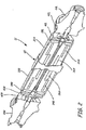
FIG. 1 shows track-layingvehicle 10 in whichcross-drive propulsion system 12 is used.Vehicle 10 comprises a heavy track-laying vehicle such as could be modified for military or construction applications.Vehicle 10 includescross-drive propulsion system 12, left-side track system 14L, right-side track system 14R,diesel motor 18 andelectric generator 20.Cross-drive propulsion system 12 includes variable field permanent magnet motors and, as such, relies on electric power to operate.Diesel engine 18 provides mechanical input togenerator 20 for producing the electric power required for operatingcross-drive propulsion system 12.Cross-drive propulsion system 12, in turn, drives left-side track system 14L and right-side track system 14R to propelvehicle 10. Left-side track system 14L includesdrive sprocket 22L,track 24L androad wheels 26L.Drive sprocket 22L is connected to receive output ofpropulsion system 12. Sprocket 22L rotates to pulltrack 24L such thatvehicle 10 rolls onroad wheels 26L.Propulsion system 12 interacts similarly with right-side track system 14R, which includes similar components such asdrive sprocket 22R. -
Propulsion system 12 relies on permanent magnet (PM) propulsion motors to transfer power to left-side track system 14L and right-side track system 14R. The PM motors provide constant power to both left-side track system 14L and right-side track system 14R under steady, high-speed operation ofvehicle 10. In order to turnvehicle 10, eithertrack system 14L ortrack system 14R must rotate faster than the other. This typically requires that up to five times as much power, as compared to what is required for straight propulsion, be delivered to the outside track, while a brake is applied to the inside track. For example, about 400 horsepower (HP) (∼298.4 kW) may be needed to drive straight, but up to about 2000 HP (∼1,492 kW) may be required at the outside track, while the equivalent of 1600 HP (∼1193 kW) needs to be absorbed from the inside track, during a turning maneuver. Thus,cross-drive propulsion system 12 includes additional PM steering motors for providing differential speed input to the cross-drive system during steering maneuvers. For example, to execute a left turn, the PM steering motors provide differential speed to planetary gear systems withincross-drive propulsion system 12 to enable a transfer gear system to transfer torque fromleft track system 14L toright track system 14R during a left turn.Propulsion system 12 utilizes variable field (VF) PM motors in order to regulate power output and speed ofvehicle 10. In order to reduce the space occupancy ofpropulsion system 12 withinvehicle 10,propulsion system 12 utilizes compound, nested VFPM motors of the present invention. The nested variable field permanent magnet motors comprise axially and radially nested motors to reduce the axial length and circumference ofdrive system 12. Thus, additional space is available withinvehicle 10, such as forpassenger compartments vehicle 10 is compatible with roads and freighting equipment. -
FIG. 2 shows a cross sectional view of cross-drivevehicle propulsion system 12 ofFIG. 1 havingcompound motors Compound motor 32A comprisespropulsion motor 34A andsteering motor 36A. Likewise,compound motor 32B comprisespropulsion motor 34B andsteering motor 36B.Cross-drive propulsion system 12 includestransfer gear system 45, which permitspropulsion motors steering motors track system motors track systems planetary gear system 38L and speed summingplanetary gear system 38R. Finally, output of speed summingplanetary gear systems track system brakes final drive assemblies drive sprockets vehicle 10. -
Compound motors vehicle 10. Accordingly,vehicle 10 is able to operate in the event of failure of eithercompound motor vehicle 10 is driven in a straight line,propulsion motors track systems steering motors propulsion motors driving track systems steering motors track system propulsion motors vehicle 10 straight at the desired speed. However,steering motors planetary gear systems transfer gear system 45 to provide additional power to rightside track system 14R and to reduce power to leftside track system 14L such that a steering operation can be efficiently executed. - Thus, the power output of each VFPM motor need not be as high as would be needed if a single PM motor were providing propulsion and steering power to each track system. Thus, total power output of
generator 20 is more efficiently transferred to left-side track system 14L and right-side track system 14R. In order to optimize the speed and torque characteristics ofpropulsion motor 34A, steeringmotor 36A,propulsion motor 34B andsteering motor 36B, each is configured as a variable field permanent magnet motor, including rotating and stationary magnetic drive elements such as permanent magnets or coil windings. Thus, each motor requires space withinpropulsion system 12 andvehicle 10 to permit axial adjustment of the rotor's magnetic drive element with respect to the stator's magnetic drive element. In order to reduce the overall dimensions ofsystem 12, in particular the width,propulsion motor 34A andsteering motor 36A are nested withincompound motor 32A, andpropulsion motor 34B andsteering motor 36B are nested withincompound motor 32B. -
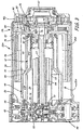
FIG. 3 showspropulsion motor 34A andsteering motor 36A nested withincompound motor 32A ofFIG. 2 .Compound motor 32A is nested betweentransfer gear system 45 and speed summingplanetary gear system 38L withinhousing 46.Planetary gear system 38L is connected with single-stagegear reduction system 40L, which is connected throughbrake 42L, andfinal drive assembly 44L to drivesprocket 22L of left-side track system 14L.Propulsion motor 34A andsteering motor 36A each comprise a variable field permanent magnet (VFPM) motor, which are built aroundcentral element 47 withincompound motor 32A.Propulsion motor 34A includes first stator 48, first coil winding 50,first rotor 52, firstpermanent magnet 54 andfirst actuator 56.Steering motor 36A includessecond stator 49, second coil winding 58,second rotor 60, secondpermanent magnet 62 andsecond actuator 64.Compound motor 32B includes similar components. Thus,compound motor 32A andcompound motor 32B each comprise a pair of nested, variable field permanent magnet motors, each having an independently operable stator and rotor. -
Central element 47 is connected tohousing 46 through, among other components,brackets central element 47 remains stationary during operation ofcompound motor 32A.Central element 47 comprises an annular body comprising a central bore, an interior surface and an exterior surface.Central element 47 includescurvature 70, which divides the annular body intofirst portion 47A and second portion 47B. First coil winding 50 is connected to the exterior surface offirst portion 47A ofcentral element 47 to form stator 48, and second coil winding 58 is connected to the interior surface of second portion 47B ofcentral element 47 to formstator 49. Thus, first coil winding 50 faces away from the central bore, and second coil winding 58 faces towards the central bore ofcentral element 47. -
Second rotor 60, which is comprised of a cylindrical shaft, is inserted into the central bore ofcentral element 47.Permanent magnet 62 is connected to the exterior ofsecond rotor 60 such that it is able to maintain a magnetic flux path with second coil winding 58.Permanent magnet 62 is connected withrotor 60 throughactuator 64 such thatmagnet 62 is axially slidable with respect tosecond rotor 60 to adjust the magnetic flux path with second coil winding 58.Rotor 60 is supported at its first end withbearings 72 atbracket 68. The first end ofrotor 60 is also connected withgear 73 for connection to transfergear system 45. The second end ofrotor 60 is connected withgear 74 for connection toplanetary gear system 38L.Gear 74 is supported withinhousing 46 bybearings 76 connected withfirst rotor 52. -
First rotor 52 comprisescylindrical body 78, inward projectingbracket 80, axial flange 82,outer ring gear 84 andinner gear 86.Permanent magnet 54 is connected to the interior ofcylindrical body 78 such that it is able to maintain a magnetic flux path with first coil winding 50.Permanent magnet 54 is connected tocylindrical body 78 withacutator 56 such thatmagnet 54 is axially slidable with respect tofirst rotor 52 to adjust the magnetic flux path between first coil winding 50.Inner gear 86 is connected to transfergear system 45 such that the inner end offirst rotor 52 is supported withincompound motor 32A and is rotatable aboutbracket 68. The second end ofrotor 52 is supported at flange 82 bybearings 76, which are supported onsecond rotor 60, such thatfirst rotor 52 is rotatable aboutcentral element 47. The second end ofrotor 52 is connected toplanetary gear system 38L throughouter gear 84. The second end ofcentral element 47 is supported withinfirst rotor 52 with bearings 88 at flange 82. Thus,first rotor 52 is freely rotatable about the exterior ofcentral element 47, andsecond rotor 60 is freely rotatable about the interior ofcentral element 47. -
Propulsion motor 34A andsteering motor 36A are nested to reduce the volume ofcompound motor 32A.First rotor 52,second rotor 60 andcentral element 47 are concentrically disposed about a central axis ofcompound motor 32A, withfirst rotor 52 andsecond rotor 60 freely and independently rotatable about the central axis.Central element 47 is fixedly secured betweenfirst rotor 52 andsecond rotor 60 about the central axis. As stated above, first stator 48 comprises first coil winding 50 disposed atfirst portion 47A ofcentral element 47. Likewise,second stator 49 comprises second coil winding 58 disposed at second portion 47B ofcentral element 47. First stator 48 andsecond stator 49 are electrically isolated from each other by, for example, the composition ofcentral element 47 or the presence of insulation betweenwindings central body 47. Thus,central element 47 is common to bothpropulsion motor 34A andsteering motor 36A, which eliminates having a separate mounting component for each of stator 48 andstator 49, thus reducing the overall diameter ofcompound motor 32A. -
Central element 47 includescurvature 70 that further collapses the diameter or radial extent ofcompound motor 32A.Curvature 70 provides a jog or bend to the annular body ofcentral element 47 such that first coil winding 50 and second coil winding 58 are recessed intocentral element 47. As such, first coil winding 50 aligns withfirst portion 47A ofcentral element 47, and second coil winding 58 aligns with second portion 47B ofcentral element 47.Curvature 70 extends deep enough such that when firstpermanent magnet 54 is withdrawn aboutactuator 56 or de-stacked from coil winding 50, firstpermanent magnet 54 is in close proximity to second portion 47B. Likewise, secondpermanent magnet 62 can be slid uponsecond actuator 64 in close proximity to and without interference fromfirst portion 47A. Thus,propulsion motor 34A is radially integrated withsteering motor 36A to reduce the width ofcompound motor 32A. Specifically,compound motor 32A need only be as wide as thewidth propulsion motor 34A when it is de-stacked, rather than the cumulative de-stacked width of bothpropulsion motor 34A andsteering motor 36A. - First coil winding 50 and second coil winding 58 of
compound motor 32A are supplied with electric power from generator 20 (FIG. 1 ) to produce electromagnetic fields. The respective electromagnetic fields interact with firstpermanent magnet 54 and secondpermanent magnet 62 to produce rotational motion offirst rotor 52 andsecond rotor 60, respectively. Firstpermanent magnet 54 and secondpermanent magnet 62 are axially adjustable onfirst rotor 52 andsecond rotor 60, respectively, to adjust the magnetic flux paths with coil winding 50 and coil winding 58, respectively. For example, at the motor corner point,permanent magnet 54 is fully engaged withactuator 56 such that the surface area ofpermanent magnet 54 completely aligns with the surface area of coil winding 50. As such, the magnetic flux exchange betweenmagnet 54 and coil winding 50 is at a maximum, and power supplied to coil winding 50 can be increased to reach the maximum torque output of propulsion motor 34. However, to increase the speed output ofrotor 52 beyond what is available at the corner point,permanent magnet 54 can be de-stacked from coil winding 50 to reduce magnetic flux exchange between the two components. The de-stacking ofpermanent magnet 54 from coil winding 50 increases the maximum rotational speed output ofrotor 52, but decreases the maximum torque output ofrotor 52. Thus,first propulsion motor 34A can act as a constant torque motor or a constant power motor. - The output of
propulsion motor 34A, i.e. the rotation of rotor 55, is transferred toplanetary gear system 38L byouter gear 84.Gear 84 rotatesplanetary gears 90, which rotatesgear carrier 91 such that the output ofrotor 52 is transferred to single-stage planetarygear reduction system 40L, whereby it can be output tocoupling 92 for transfer tofinal drive assembly 44L (FIG. 2 ). Likewise, the rotation of rotor 55 is transferred to transfergear system 45 throughinner gear 86 such that its output is transferred tofinal drive assembly 44R. In a similar fashion,compound motor 32B drives a rotor of a VFPM propulsion motor to redundantly drivetrack systems compound motor 32A andcompound motor 32B are coupled atgear system 94 andbevel gear 95 such thatcompound motors side track system 14L and right-side track system 14R. Thus,vehicle 10 is driven forward or backward at a constant speed such that it moves in a generally straight direction. - In order to perform a left-hand turning maneuver for
vehicle 10, right-side track system 14R must be driven faster than left-side track system 14L, which requires additional energy input.Compound motor 32A includes steeringmotor 36A, which provides a steering input topropulsion system 12, and throughgear transfer system 45, speed summingplanetary gear system 38L and speed summingplanetary gear system 38R, redistributes power from one track system to the other. -
Steering motor 36A is coupled toplanetary gear 90 of speed summingplanetary gear system 38L throughsun gear 74.Propulsion motor 34A is coupled toplanetary gear 90 throughring gear 84.Ring gear 84 offirst rotor 52 andsun gear 74 ofsecond rotor 60 work together to turnplanetary gears 90 andgear carrier 91.Steering motor 36A andpropulsion motor 34A are also coupled to speed summingplanetary gear system 38R throughtransfer gear assembly 45.Transfer gear system 45 works to reverse the relative outputs ofsteering motors steering motors sun gear 74 of speed summing planetary gear system 38A with negative rotational velocity and the sun gear of speed summing planetary gear system 38B with positive rotational velocity.Ring gear 84 of speed summing planetary gear system 38A, and the ring gear of speed summing planetary gear system 38B are continued to be driven at the same speed bypropulsion motor 34A andpropulsion motor 34B. This results ingear carrier 91 of speed summingplanetary system 38L slowing down, and the gear carrier of speed summingplanetary system 38R speeding up. Thus, torque is transferred from left-side track system 14L to right-side track system 14R through the cross-drive gearing ofpropulsion system 12. This happens without impacting the output ofpropulsion motors motors side track system 14L to right-side track system 14R. For example, the cross-drive if the gearing is ninety-eight percent efficient, 2000 HP (∼1492kW) can be transferred from left-side track system 14L to right-side track system 14R with the steer motors only providing a combined 40 HP (∼29.8 kW) topropulsion system 12. - Thus, by using the nested permanent magnet drive systems of the present invention,
propulsion system 12 is able to provide on-demand power to left-side track system 14L and right-side track system 16R without the use of large, high capacity permanent magnet motors having large individual power consumption. Thus, smaller motors, such aspropulsion motor 34A andsteering motor 36A, can be used to keep the size of propulsion system small. Additionally, steeringmotor 36A is nested withinpropulsion motor 34A to further reduce the diameter and width ofcompound motor 32A. The compactness ofcompound motor 32A is particularly well suited for cross-drive propulsion systems. However,compound motor 32A is suited for other applications and can be modified accordingly. -
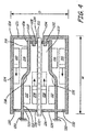
FIG. 4 shows a schematic diagram of nested variable field dynamoelectric machine 100, which represents a simplified, generalized embodiment ofcompound motor 32A ofFIG. 3 . Dynamoelectric machine 100 comprises one embodiment of the present invention that can be modified for use in a variety of applications. Dynamoelectric machine 100 includesfirst rotor shaft 102,second rotor shaft 104 andstator body 106. Firstmagnetic drive element 108 is mounted tofirst rotor shaft 102 to form a first rotor, and secondmagnetic drive element 110 is mounted tosecond rotor shaft 104 to form a second rotor.Stator body 106 includes thirdmagnetic drive element 112, which is mounted tointerior surface 114 to form a first stator, and fourthmagnetic drive element 116, which is mounted toexterior surface 118 ofstator body 106 to form a second stator. Thus, dynamoelectric machine 100 is configured to include two separately interacting sets of rotors and stators. -
Stator body 106 comprises an annular body and is fixed atfirst end 120 such that it remains stationary whilefirst rotor shaft 102 andsecond rotor shaft 104 are permitted to rotate about centerline CL.First rotor shaft 102 comprises a cylindrical shaft that extends throughcentral bore 122 ofstator body 106 such that it rotates withinstator body 106.Second rotor shaft 104 comprises a cylindrical shell that surroundsstator body 106 such that it rotates aboutstator body 106.Second rotor shaft 104 includesannular body 124,support bracket 126 andflange 128, andstator body 106 includessupport bracket 129. - A first end of
second rotor shaft 104 is supported at the outer surface ofstator body 106 bybearings 130, which are radially displaced from centerline CL bysupport bracket 120 ofstator body 106. A second end ofsecond rotor shaft 104 is supported at the inner surface ofstator body 106 bybearings 132 atflange 128, which are radially displaced fromannular body 124 bysupport bracket 126. Thus,second rotor shaft 104 is radially displaced fromfirst rotor shaft 102 and is permitted to rotate freely about centerline CL outside ofstator body 106 in either a forward or backward direction.Second rotor shaft 104 is also supported on the outer surface offirst rotor shaft 102 bybearings 134 atflange 128.First rotor shaft 102 is supported withinstator body 106 bybearings 134 atflange 128, and bybearings 136 atsupport bracket 129. Thus,first rotor shaft 102 is permitted to rotate freely about centerline CL withinstator body 106 in either a forward or a backward direction. Thus,first rotor shaft 102 andsecond rotor shaft 104 are concentrically disposed about centerline CL to reduce diameter D. Likewise,first rotor shaft 102 andsecond rotor shaft 104 are axially integrated to reduce width W. -
First rotor shaft 102 is inserted intostator body 106 such that firstmagnetic drive element 108 aligns with thirdmagnetic drive element 112.Second rotor shaft 104 is disposed aboutstator body 106 such that secondmagnetic drive element 110 aligns with fourthmagnetic drive element 116. Firstmagnetic drive element 108 is axially displaceable alongfirst rotor shaft 102 to vary the interaction with thirdmagnetic drive element 112. Firstmagnetic drive element 108 is displaced alongfirst rotor shaft 102 such that it extends within fourthmagnetic drive element 116, thus avoiding the necessity for additional axial length of machine 100. Likewise, secondmagnetic drive element 110 is axially displaceable alongsecond rotor shaft 104 to vary the interaction with fourthmagnetic drive element 116. Secondmagnetic drive element 110 is displaced alongsecond rotor shaft 104 such that it extends to surround thirdmagnetic drive element 112, thus avoiding the necessity for additional axial length of machine 100.Magnetic drive elements Stator body 106 includesbend 138, which permits thirdmagnetic drive element 112 and fourthmagnetic drive element 116 to be brought closer to being radially aligned. As such, diameter D of machine 100 is reduced. However,bend 138 is not so deep as to prevent axial movement of firstmagnetic drive element 108 and secondmagnetic drive element 110. - Dynamoelectric machine 100 can be configured as having two nested PM motors, a conventional PM motor nested within an inside out PM motor, as described above. However, dynamoelectric machine 100 can be configured as other types of electric motors, such as induction, switched reluctance, DC brush motors, or the like. Dynamoelectric machine 100 can also be configured to operate either as motor or a generator.
First rotor shaft 102 andsecond rotor shaft 104 independently rotate about centerline CL and can be independently supplied with power and controlled with switches and inverters as is required of specific applications. Additionally, mechanical power can be taken off of or supplied tofirst rotor shaft 102 andsecond rotor shaft 104 in a variety of locations as is needed.Magnetic drive elements - Although the present invention has been described with reference to preferred embodiments, workers skilled in the art will recognize that changes may be made in form and detail without departing from the spirit and scope of the invention.
- Further aspects of the disclosure will now be described according to the folowing numbered clauses:
- 1. A nested permanent magnet drive system comprising:
- a central element comprising:
- an annular body comprising:
- a central bore;
- a first armature portion; and
- a second armature portion;
- a first outward facing magnetic drive element connected to the first armature portion to form a first stator; and
- a first inward facing magnetic drive element connected to the second armature portion to form a second stator;
- an annular body comprising:
- a first rotor comprising:
- a cylindrical body concentrically surrounding the annular body; and
- a second inward facing magnetic drive element connected to an inner surface of the cylindrical rotor body and for electromagnetically interacting with the first outward facing magnetic drive element; and
- a second rotor comprising:
- a shaft extending through the central bore; and
- a second outward facing magnetic drive element connected to an outer surface of the shaft and for electromagnetically interacting with the first inward facing magnetic drive element.
- a central element comprising:
- 2. The nested permanent magnet drive system of clause 1 wherein the annular body includes a jog such that the first outward facing magnetic drive element axially aligns with the second armature portion, and the first inward facing magnetic drive element axially aligns with the first armature portion.
- 3. The nested permanent magnet drive system of clause 1 wherein:
- the first outward facing magnetic drive element and the first inward facing magnetic drive element comprise coil windings; and
- the second outward facing magnetic drive element and the second inward facing magnetic drive element comprise permanent magnets.
- 4. The nested permanent magnet drive system of clause 1 wherein:
- the second outward facing magnetic drive element is connected to the outer surface of the shaft with a first actuator such that the second outward facing magnetic drive element is axially displaceable; and
- the second inward facing magnetic drive element is connected to the inner surface of the cylindrical body with a second actuator such that the second inward facing magnetic drive element is axially displaceable.
- 5. The nested permanent magnet drive system of clause 1 wherein the cylindrical body further comprises:
- a bracket projecting radially inward from the cylindrical body; and
- a flange projecting axially into the central bore from the bracket for supporting the cylindrical body concentrically with the annular body.
- 6. The nested permanent magnet drive system of clause 5 wherein the annular body further comprises a support projecting radially inward from the annular body for supporting the annular body concentrically with the shaft.
- 7. The nested permanent magnet drive system of clause 6 wherein the cylindrical body further comprises:
- a first end supported on an exterior surface of the annular body by a first bearing; and
- a second end supported on an exterior surface of the shaft by a second bearing at the flange.
- 8. The nested permanent magnet drive system of clause 7 wherein the annular body further comprises:
- a first end supported on the shaft by a third bearing at the support; and
- a second end supported on the flange by a fourth bearing.
- 9. The nested permanent magnet drive system of clause 1 and further comprising:
- a ring gear attached to the cylindrical body;
- a spur gear attached to the shaft; and
- a planetary gear linking the ring gear with the spur gear for coordinating output of the nested permanent magnet drive system.
- 10. A dual permanent magnet motor comprising:
- a first motor comprising:
- a cylindrical stator body having a first coil forming a first stator winding mounted to an exterior of the cylindrical stator body; and
- a first rotor configured for rotation about the cylindrical stator and having a first permanent magnet array configured for rotating about the first stator winding; and
- a second motor comprising:
- a second coil forming a second stator winding mounted to an interior of the cylindrical stator body; and
- a second rotor configured for rotation within the cylindrical stator and having a second permanent magnet array configured for rotating within the second stator winding.
- a first motor comprising:
- 11. The dual permanent magnet motor of
clause 10 wherein the cylindrical stator body includes a curvature such that the first stator winding and the second stator winding are recessed within the cylindrical stator. - 12. The dual permanent magnet motor of
clause 10 wherein:- the first permanent magnet array is axially adjustable about the first rotor to adjust magnetic flux interaction between the first permanent magnet array and the first stator winding; and
- the second permanent magnet array is axially adjustable about the second rotor to adjust magnetic flux interaction between the second permanent magnet array and the second stator winding.
- 13. The dual permanent magnet motor of
clause 10 wherein a first end of the cylindrical stator body is supported by bearings at the second rotor, and a second end of the cylindrical stator body is supported by bearings at the first rotor. - 14. The dual permanent magnet motor of
clause 10 wherein a first end of the first rotor is supported by bearings on an exterior surface of the stator body, and a second end of the first rotor is supported between bearings on an exterior surface of the second rotor and bearings on an interior surface of the stator body. - 15. A dynamoelectric machine comprising:
- a first rotor shaft for rotating about a central axis of the machine and having a first magnetic drive element disposed about an outer circumference of the first rotor shaft;
- a second rotor shaft for rotating about the first rotor shaft and having a second magnetic drive element disposed about an inner circumference of the second rotor shaft; and
- a central element disposed between the first rotor shaft and the second rotor shaft and configurable to remain stationary while the first rotor shaft and the second rotor shaft rotate about the central axis, and wherein the central element includes a third magnetic drive element for interacting with the first magnetic drive element, and a fourth magnetic drive element for interacting with the second magnetic drive element.
- 16. The dynamoelectric machine of clause 15 wherein the central element includes a curvature such that the third magnetic drive element and the fourth magnetic drive element are recessed within the central element.
- 17. The dynamoelectric machine of clause 15 wherein:
- the first electromagnet element is axially adjustable about the first rotor shaft to adjust magnetic flux interaction between the first magnetic drive element and the third magnetic drive element; and
- the second electromagnet element is axially adjustable within the second rotor shaft to adjust magnetic flux interaction between the second electromagnet element and the fourth electromagnet element.
- 18. The dynamoelectric machine of clause 15 wherein a first end of the central element is supported by bearings on the second rotor shaft, and a second end of the central element is supported by bearings on the first rotor shaft.
- 19. The dynamoelectric machine of clause 15 wherein a first end of the second rotor shaft is supported by bearings on an exterior surface of the stator, and a second end of the second rotor shaft is supported between bearings on an exterior surface of the first rotor shaft and bearings on an interior surface of the central element.
- 20. The dynamoelectric machine of clause 15 and further comprising:
- a spur gear attached to the first rotor shaft;
- a ring gear attached to the second rotor shaft; and
- a planetary gear linking the ring gear with the spur gear for coordinating output of the first rotor shaft and the second rotor shaft.
Claims (9)
- A dual permanent magnet motor (32A; 32B; 100) comprising:a first motor (34A; 34B) comprising:a cylindrical stator body having a first coil forming a first stator winding (50; 116) mounted to an exterior of the cylindrical stator body; anda first rotor (52; 104) configured for rotation about the cylindrical stator body and having a first permanent magnet array (54; 110) configured for rotating about the first stator winding; anda second motor (36A; 36B) comprising:a second coil forming a second stator winding (58; 112) mounted to an interior of the cylindrical stator body; anda second rotor (60; 102) configured for rotation within the cylindrical stator body and having a second permanent magnet array (62; 108) configured for rotating within the second stator winding;wherein the cylindrical stator body includes a curvature such that the first stator winding and the second stator winding are recessed within the cylindrical stator.
- The dual permanent magnet motor of claim 1 wherein:the first permanent magnet array is axially adjustable about the first rotor to adjust magnetic flux interaction between the first permanent magnet array and the first stator winding; andthe second permanent magnet array is axially adjustable about the second rotor to adjust magnetic flux interaction between the second permanent magnet array and the second stator winding.
- The dual permanent magnet motor of claim 1 or 2 wherein a first end of the cylindrical stator body is supported by bearings (72; 136) at the second rotor, and a second end of the cylindrical stator body is supported by bearings (88; 132) at the first rotor.
- The dual permanent magnet motor of any of claims 1, 2 or 3 wherein a first end of the first rotor is supported by bearings (130) on an exterior surface of the cylindrical stator body, and a second end of the first rotor is supported between bearings (76; 134) on an exterior surface of the second rotor and bearings (88; 132) on an interior surface of the cylindrical stator body.
- A dynamoelectric machine (32A; 32B; 100) comprising:a first rotor shaft (102) for rotating about a central axis of the machine and having a first magnetic drive element (62; 108) disposed about an outer circumference of the first rotor shaft;a second rotor shaft (104) for rotating about the first rotor shaft and having a second magnetic drive element (54; 110) disposed about an inner circumference of the second rotor shaft; anda central element (47; 106) disposed between the first rotor shaft and the second rotor shaft and configurable to remain stationary while the first rotor shaft and the second rotor shaft rotate about the central axis;wherein the central element includes a third magnetic drive element (58; 112) for interacting with the first magnetic drive element, and a fourth magnetic drive element (50; 116) for interacting with the second magnetic drive element; andwherein the central element includes a curvature (70; 138) such that the third magnetic drive element and the fourth magnetic drive element are recessed within the central element.
- The dynamoelectric machine of claim 5 wherein:the first magnetic drive element is axially adjustable about the first rotor shaft to adjust magnetic flux interaction between the first magnetic drive element and the third magnetic drive element; andthe second magnetic drive element is axially adjustable within the second rotor shaft to adjust magnetic flux interaction between the second magnetic drive element and the fourth magnetic drive element.
- The dynamoelectric machine of claim 5 or 6, wherein a first end of the central element is supported by bearings (88; 132) on the second rotor shaft, and a second end of the central element is supported by bearings (72; 136) on the first rotor shaft.
- The dynamoelectric machine of any of claims 5, 6 or 7, wherein a first end of the second rotor shaft is supported by bearings (130) on an exterior surface of the central element, and a second end of the second rotor shaft is supported between bearings (76; 134) on an exterior surface of the first rotor shaft and bearings (88; 132) on an interior surface of the central element.
- The dynamoelectric machine of any of claims 5, 6 or 7, and further comprising:a spur gear (74) attached to the first rotor shaft;a ring gear (84) attached to the second rotor shaft; anda planetary gear (90) linking the ring gear with the spur gear for coordinating output of the first rotor shaft and the second rotor shaft.
Applications Claiming Priority (2)
| Application Number | Priority Date | Filing Date | Title |
|---|---|---|---|
| US11/706,882 US7642684B2 (en) | 2007-02-15 | 2007-02-15 | Nested variable field dynamoelectric machine |
| EP08724755.7A EP2158666B1 (en) | 2007-02-15 | 2008-01-24 | Nested variable field dynamoelectric machine |
Related Parent Applications (2)
| Application Number | Title | Priority Date | Filing Date |
|---|---|---|---|
| EP08724755.7A Division EP2158666B1 (en) | 2007-02-15 | 2008-01-24 | Nested variable field dynamoelectric machine |
| EP08724755.7A Division-Into EP2158666B1 (en) | 2007-02-15 | 2008-01-24 | Nested variable field dynamoelectric machine |
Publications (1)
| Publication Number | Publication Date |
|---|---|
| EP3203619A1 true EP3203619A1 (en) | 2017-08-09 |
Family
ID=39690665
Family Applications (2)
| Application Number | Title | Priority Date | Filing Date |
|---|---|---|---|
| EP17163807.5A Withdrawn EP3203619A1 (en) | 2007-02-15 | 2008-01-24 | Nested variable field dynamoelectric machine |
| EP08724755.7A Not-in-force EP2158666B1 (en) | 2007-02-15 | 2008-01-24 | Nested variable field dynamoelectric machine |
Family Applications After (1)
| Application Number | Title | Priority Date | Filing Date |
|---|---|---|---|
| EP08724755.7A Not-in-force EP2158666B1 (en) | 2007-02-15 | 2008-01-24 | Nested variable field dynamoelectric machine |
Country Status (8)
| Country | Link |
|---|---|
| US (1) | US7642684B2 (en) |
| EP (2) | EP3203619A1 (en) |
| JP (1) | JP2010519886A (en) |
| KR (1) | KR20100014886A (en) |
| CN (1) | CN101657954B (en) |
| IL (1) | IL200481A (en) |
| WO (1) | WO2008100372A2 (en) |
| ZA (1) | ZA200905814B (en) |
Cited By (1)
| Publication number | Priority date | Publication date | Assignee | Title |
|---|---|---|---|---|
| CN112003437A (en) * | 2020-09-08 | 2020-11-27 | 齐鲁工业大学 | Composite structure wind driven generator and power generation system |
Families Citing this family (27)
| Publication number | Priority date | Publication date | Assignee | Title |
|---|---|---|---|---|
| US8529620B2 (en) * | 2007-05-01 | 2013-09-10 | Ottavio Alfieri | Inwardly-bowed tricuspid annuloplasty ring |
| US7923874B2 (en) * | 2009-06-17 | 2011-04-12 | Hamilton Sundstrand Corporation | Nested torsional damper for an electric machine |
| US20110006545A1 (en) * | 2009-07-08 | 2011-01-13 | Hamilton Sundstrand Corporation | Nested exciter and main generator stages for a wound field generator |
| US8207644B2 (en) * | 2009-07-14 | 2012-06-26 | Hamilton Sundstrand Corporation | Hybrid cascading lubrication and cooling system |
| CN102548819A (en) | 2009-10-13 | 2012-07-04 | 本田技研工业株式会社 | Hybrid vehicle |
| WO2011045965A1 (en) * | 2009-10-13 | 2011-04-21 | 本田技研工業株式会社 | Hybrid vehicle |
| US8058757B2 (en) * | 2009-12-15 | 2011-11-15 | Hamilton Sundstrand Corporation | Electric motor with passive integral brake |
| US8742641B2 (en) | 2010-11-23 | 2014-06-03 | Remy Technologies, L.L.C. | Concentric motor power generation and drive system |
| US8932350B2 (en) | 2010-11-30 | 2015-01-13 | Edwards Lifesciences Corporation | Reduced dehiscence annuloplasty ring |
| US8872403B2 (en) * | 2010-12-10 | 2014-10-28 | Mario A. Galvan | Electrical system and method for sustaining an external load |
| US20150042186A1 (en) * | 2010-12-10 | 2015-02-12 | Mario A. Galvan | Electrical system and method for sustaining an external load |
| US20130028737A1 (en) * | 2011-07-25 | 2013-01-31 | Sports Art Industrial Co., Ltd. | Adjustable wind turbine generating device |
| US9000644B2 (en) | 2012-06-05 | 2015-04-07 | Remy Technologies, L.L.C. | Concentric motor power generation and drive system |
| US9991771B2 (en) * | 2013-11-05 | 2018-06-05 | The University Of Maryland, Baltimore County | Active control system for a variable electromotive-force generator with applications to wind turbines, ships, and hybrid vehicles |
| US11296638B2 (en) | 2014-08-01 | 2022-04-05 | Falcon Power, LLC | Variable torque motor/generator/transmission |
| US9479037B2 (en) * | 2014-08-01 | 2016-10-25 | Falcon Power, LLC | Variable torque motor/generator/transmission |
| US10724999B2 (en) | 2015-06-04 | 2020-07-28 | Rolls-Royce Corporation | Thermal spray diagnostics |
| US20170273523A1 (en) * | 2016-03-25 | 2017-09-28 | Bissell Homecare, Inc. | Brushroll for vacuum cleaner |
| US10513986B2 (en) | 2016-10-05 | 2019-12-24 | Rolls-Royce North American Technologies, Inc. | Counter-rotating electric generator in turbine engine |
| US10312781B2 (en) * | 2016-10-05 | 2019-06-04 | Rolls-Royce North American Technologies, Inc. | Multiple coil electric generator in turbine engine |
| CN111342631B (en) * | 2017-04-28 | 2021-04-02 | 深圳市大疆创新科技有限公司 | Drives, laser measuring devices and mobile platforms |
| KR101927493B1 (en) * | 2018-04-26 | 2018-12-10 | 성상준 | Transmission integral type electrical motor having double rotors |
| US11060593B2 (en) | 2018-10-19 | 2021-07-13 | Hamilton Sundstrand Corporation | Jam-tolerant electric rotary actuator |
| US11923733B2 (en) * | 2020-08-28 | 2024-03-05 | Quantentech Limited | High efficiency high density motor and generator with multiple airgaps |
| EP3968503B1 (en) * | 2020-08-31 | 2025-02-12 | General Electric Company | Turbomachine equipped with an embedded electric machine having a segmented and movable stator |
| KR102569759B1 (en) * | 2022-12-15 | 2023-08-22 | 김병국 | load motor for testing high speed motor |
| CN116928000B (en) * | 2023-07-31 | 2026-04-28 | 宁波大学 | A water pipeline power generation device with flow and pressure regulation functions |
Citations (5)
| Publication number | Priority date | Publication date | Assignee | Title |
|---|---|---|---|---|
| US4728841A (en) * | 1986-06-16 | 1988-03-01 | Sundstrand Corporation | Dual permanent magnet generator construction |
| EP0828340A2 (en) * | 1996-09-06 | 1998-03-11 | Toyota Jidosha Kabushiki Kaisha | Power output apparatus |
| US6373160B1 (en) * | 1998-01-30 | 2002-04-16 | Schroedl Manfred | Electric machine |
| WO2003069763A1 (en) * | 2002-02-12 | 2003-08-21 | Nissan Motor Co., Ltd. | Electric rotating machine |
| US20050218740A1 (en) * | 2004-03-30 | 2005-10-06 | Stout David E | Low profile generator configuration |
Family Cites Families (33)
| Publication number | Priority date | Publication date | Assignee | Title |
|---|---|---|---|---|
| JPS63228941A (en) * | 1987-03-18 | 1988-09-22 | Koji Onuma | Compound motor |
| JPS6423747A (en) * | 1987-07-17 | 1989-01-26 | Iwata Air Compressor Mfg | Composite motor |
| US5168946A (en) | 1991-09-09 | 1992-12-08 | General Electric Company | Track-laying vehicle electric drive system |
| JPH06351206A (en) | 1993-04-14 | 1994-12-22 | Meidensha Corp | Hybrid excitation-type permanent-magnet synchronous rotating machine |
| US5578878A (en) | 1994-08-30 | 1996-11-26 | United Technologies Motor Systems, Inc. | Counterbalanced electric motor |
| US5578885A (en) | 1994-12-22 | 1996-11-26 | General Motors Corporation | Rotor assembly for hybrid alternator |
| US5874796A (en) | 1995-02-10 | 1999-02-23 | Petersen; Christian C. | Permanent magnet D.C. motor having a radially-disposed working flux gap |
| US5793136A (en) * | 1996-06-05 | 1998-08-11 | Redzic; Sabid | Differential motor/generator apparatus |
| CH690632A5 (en) * | 1996-11-27 | 2000-11-15 | Ebauchesfabrik Eta Ag | electromagnetic motor with two coaxial rotors. |
| EP0945964B1 (en) * | 1998-03-25 | 2003-11-12 | Nissan Motor Co., Ltd. | Motor/generator |
| JP3559891B2 (en) * | 1998-06-22 | 2004-09-02 | 日産自動車株式会社 | Cooling structure of multilayer motor |
| US6768237B1 (en) * | 1999-06-21 | 2004-07-27 | Manfred Schroedl | Electric motor |
| EP1164688B1 (en) * | 2000-06-14 | 2007-07-18 | Nissan Motor Company, Limited | Electric rotary machine having a stator support structure |
| JP4269544B2 (en) * | 2000-09-14 | 2009-05-27 | 株式会社デンソー | Multi-rotor synchronous machine |
| JP4722309B2 (en) | 2000-12-27 | 2011-07-13 | 三菱電機株式会社 | Rotating electric machine and pulley drive device using the rotating electric machine |
| US6700242B2 (en) | 2000-12-28 | 2004-03-02 | Hideo Kawamura | Magnetic flux controls for permanent-magnet motor-generator |
| GB0109336D0 (en) | 2001-04-17 | 2001-05-30 | Secr Defence | Drive configuration for a skid steered vehicle |
| US6700288B2 (en) | 2001-08-15 | 2004-03-02 | Drs Power & Control Technologies, Inc. | High speed rotor |
| US6555941B1 (en) * | 2002-03-08 | 2003-04-29 | Dura-Trac Motors, Inc. | Brushless permanent magnet motor or alternator with variable axial rotor/stator alignment to increase speed capability |
| WO2003084025A1 (en) * | 2002-04-01 | 2003-10-09 | Nissan Motor Co., Ltd. | Stator mounting for a double rotor electric motor |
| US6894418B2 (en) | 2002-07-30 | 2005-05-17 | Comprehensive Power, Inc. | Nested stator coils for permanent magnet machines |
| KR20040017608A (en) * | 2002-08-22 | 2004-02-27 | 삼성에스디아이 주식회사 | Complex type filament support and vacuum fluorescent display with the support |
| JP2004147412A (en) * | 2002-10-23 | 2004-05-20 | Toyota Motor Corp | Multi-layer coaxial rotating electric machine and hybrid drive system using the same |
| EP3358723A1 (en) * | 2002-12-20 | 2018-08-08 | Tai-Her Yang | Electrical machine with structure for axially moving the rotor using centrifugal force |
| US7030528B2 (en) * | 2003-02-06 | 2006-04-18 | General Motors Corporation | Dual concentric AC motor |
| FR2852162B1 (en) * | 2003-03-06 | 2005-09-23 | Leroy Somer Moteurs | ROTATING ELECTRIC MACHINE COMPRISING A STATOR AND TWO ROTORS |
| JP3849672B2 (en) * | 2003-06-05 | 2006-11-22 | 日産自動車株式会社 | Bearing lubrication structure of multi-shaft multilayer motor |
| US6943478B2 (en) * | 2003-11-14 | 2005-09-13 | Dura-Trac Motors, Inc. | Brushless permanent magnet wheel motor with variable axial rotor/stator alignment |
| JP4591910B2 (en) * | 2004-03-08 | 2010-12-01 | 株式会社アマダ | Characteristics switching motor |
| DE102004028355B4 (en) * | 2004-06-11 | 2011-12-29 | Siemens Ag | driving means |
| US7285890B2 (en) | 2005-03-30 | 2007-10-23 | Comprehensive Power, Inc. | Magnet retention on rotors |
| US7530912B2 (en) * | 2005-04-27 | 2009-05-12 | Arvinmeritor Technology, Llc | Driveline motor with planetary gear system |
| US20070052312A1 (en) | 2005-09-08 | 2007-03-08 | Anatoliy Stanetskiy | Permanent magnetic motor |
-
2007
- 2007-02-15 US US11/706,882 patent/US7642684B2/en active Active
-
2008
- 2008-01-24 WO PCT/US2008/000902 patent/WO2008100372A2/en not_active Ceased
- 2008-01-24 EP EP17163807.5A patent/EP3203619A1/en not_active Withdrawn
- 2008-01-24 KR KR1020097018226A patent/KR20100014886A/en not_active Ceased
- 2008-01-24 CN CN2008800122092A patent/CN101657954B/en not_active Expired - Fee Related
- 2008-01-24 EP EP08724755.7A patent/EP2158666B1/en not_active Not-in-force
- 2008-01-24 JP JP2009549583A patent/JP2010519886A/en not_active Ceased
-
2009
- 2009-08-18 IL IL200481A patent/IL200481A/en not_active IP Right Cessation
- 2009-08-21 ZA ZA200905814A patent/ZA200905814B/en unknown
Patent Citations (5)
| Publication number | Priority date | Publication date | Assignee | Title |
|---|---|---|---|---|
| US4728841A (en) * | 1986-06-16 | 1988-03-01 | Sundstrand Corporation | Dual permanent magnet generator construction |
| EP0828340A2 (en) * | 1996-09-06 | 1998-03-11 | Toyota Jidosha Kabushiki Kaisha | Power output apparatus |
| US6373160B1 (en) * | 1998-01-30 | 2002-04-16 | Schroedl Manfred | Electric machine |
| WO2003069763A1 (en) * | 2002-02-12 | 2003-08-21 | Nissan Motor Co., Ltd. | Electric rotating machine |
| US20050218740A1 (en) * | 2004-03-30 | 2005-10-06 | Stout David E | Low profile generator configuration |
Cited By (2)
| Publication number | Priority date | Publication date | Assignee | Title |
|---|---|---|---|---|
| CN112003437A (en) * | 2020-09-08 | 2020-11-27 | 齐鲁工业大学 | Composite structure wind driven generator and power generation system |
| CN112003437B (en) * | 2020-09-08 | 2022-03-18 | 齐鲁工业大学 | A composite structure wind turbine and power generation system |
Also Published As
| Publication number | Publication date |
|---|---|
| IL200481A0 (en) | 2011-08-01 |
| US20080197730A1 (en) | 2008-08-21 |
| JP2010519886A (en) | 2010-06-03 |
| EP2158666A2 (en) | 2010-03-03 |
| WO2008100372A3 (en) | 2008-10-30 |
| US7642684B2 (en) | 2010-01-05 |
| KR20100014886A (en) | 2010-02-11 |
| EP2158666A4 (en) | 2014-05-14 |
| CN101657954B (en) | 2012-11-28 |
| IL200481A (en) | 2013-08-29 |
| ZA200905814B (en) | 2010-07-28 |
| EP2158666B1 (en) | 2017-05-10 |
| WO2008100372A2 (en) | 2008-08-21 |
| CN101657954A (en) | 2010-02-24 |
Similar Documents
| Publication | Publication Date | Title |
|---|---|---|
| US7642684B2 (en) | Nested variable field dynamoelectric machine | |
| US11146132B2 (en) | Permanent magnet electric machine with variable magnet orientation | |
| US20100327791A1 (en) | Electric machine with non-coaxial rotors | |
| US20100252341A1 (en) | Electric rotary machine | |
| US10333376B2 (en) | Double-rotor switched reluctance machine | |
| US20080142284A1 (en) | Double-sided dual-shaft electrical machine | |
| CN104753285B (en) | Arc surface two degrees of freedom permanent magnet hub motor | |
| US7750527B2 (en) | Motor/generator | |
| GB2278242A (en) | Electromagnetic transmission system including variable-speed electric motor | |
| US20080211432A1 (en) | All Wheel Drive Vehicle | |
| EP3297135B1 (en) | Dynamo/motor with built-in speed converter | |
| CN116572721B (en) | Drive assembly, vehicle and control method | |
| US20130187501A1 (en) | Electric motor assembly with electric phasing of rotor segments to reduce back electromotive force | |
| KR102090535B1 (en) | Driving apparatus for electric vehicle | |
| CN119585131A (en) | Compact electric axle assemblies | |
| US20100060091A1 (en) | Electromagnetic rotor machine | |
| CN117097098A (en) | Active steering systems and vehicles that cancel mechanical transmission devices | |
| EP3036122B1 (en) | An electrical motor construction provided with a planetary gear system | |
| US20220407375A1 (en) | Motor | |
| EP1835600A2 (en) | Motor/generator | |
| JP3067594B2 (en) | Vehicle drive device and drive control method thereof | |
| US12240308B2 (en) | Axle assembly for an electric vehicle, vehicle, and method for operating an axle assembly | |
| JPH07143696A (en) | Electric motor | |
| KR101751511B1 (en) | Driving device for electric vehicle | |
| JP2023092017A (en) | Steering reaction force generator |
Legal Events
| Date | Code | Title | Description |
|---|---|---|---|
| PUAI | Public reference made under article 153(3) epc to a published international application that has entered the european phase |
Free format text: ORIGINAL CODE: 0009012 |
|
| STAA | Information on the status of an ep patent application or granted ep patent |
Free format text: STATUS: THE APPLICATION HAS BEEN PUBLISHED |
|
| AC | Divisional application: reference to earlier application |
Ref document number: 2158666 Country of ref document: EP Kind code of ref document: P |
|
| AK | Designated contracting states |
Kind code of ref document: A1 Designated state(s): AT BE BG CH CY CZ DE DK EE ES FI FR GB GR HR HU IE IS IT LI LT LU LV MC MT NL NO PL PT RO SE SI SK TR |
|
| STAA | Information on the status of an ep patent application or granted ep patent |
Free format text: STATUS: REQUEST FOR EXAMINATION WAS MADE |
|
| 17P | Request for examination filed |
Effective date: 20180208 |
|
| RBV | Designated contracting states (corrected) |
Designated state(s): AT BE BG CH CY CZ DE DK EE ES FI FR GB GR HR HU IE IS IT LI LT LU LV MC MT NL NO PL PT RO SE SI SK TR |
|
| STAA | Information on the status of an ep patent application or granted ep patent |
Free format text: STATUS: EXAMINATION IS IN PROGRESS |
|
| 17Q | First examination report despatched |
Effective date: 20201105 |
|
| GRAP | Despatch of communication of intention to grant a patent |
Free format text: ORIGINAL CODE: EPIDOSNIGR1 |
|
| STAA | Information on the status of an ep patent application or granted ep patent |
Free format text: STATUS: GRANT OF PATENT IS INTENDED |
|
| INTG | Intention to grant announced |
Effective date: 20240321 |
|
| STAA | Information on the status of an ep patent application or granted ep patent |
Free format text: STATUS: THE APPLICATION IS DEEMED TO BE WITHDRAWN |
|
| 18D | Application deemed to be withdrawn |
Effective date: 20240723 |