EP3203594A1 - Method for preventing chaffing between a linear detector cable and a protective outer sheath - Google Patents
Method for preventing chaffing between a linear detector cable and a protective outer sheath Download PDFInfo
- Publication number
- EP3203594A1 EP3203594A1 EP17153966.1A EP17153966A EP3203594A1 EP 3203594 A1 EP3203594 A1 EP 3203594A1 EP 17153966 A EP17153966 A EP 17153966A EP 3203594 A1 EP3203594 A1 EP 3203594A1
- Authority
- EP
- European Patent Office
- Prior art keywords
- tube
- end portion
- distal end
- protective sheath
- polymer
- Prior art date
- Legal status (The legal status is an assumption and is not a legal conclusion. Google has not performed a legal analysis and makes no representation as to the accuracy of the status listed.)
- Granted
Links
- 230000001681 protective effect Effects 0.000 title claims abstract description 51
- 238000000034 method Methods 0.000 title claims abstract description 35
- 229920000642 polymer Polymers 0.000 claims abstract description 48
- 230000007704 transition Effects 0.000 claims description 41
- 238000001514 detection method Methods 0.000 description 13
- 238000010276 construction Methods 0.000 description 4
- 238000005299 abrasion Methods 0.000 description 3
- 239000011248 coating agent Substances 0.000 description 3
- 238000000576 coating method Methods 0.000 description 3
- 239000004810 polytetrafluoroethylene Substances 0.000 description 3
- 229920001343 polytetrafluoroethylene Polymers 0.000 description 3
- 238000010438 heat treatment Methods 0.000 description 2
- 229910001220 stainless steel Inorganic materials 0.000 description 2
- 239000010935 stainless steel Substances 0.000 description 2
- 238000005452 bending Methods 0.000 description 1
- 239000004020 conductor Substances 0.000 description 1
- 238000002788 crimping Methods 0.000 description 1
- 238000009434 installation Methods 0.000 description 1
- 238000009413 insulation Methods 0.000 description 1
- 238000012986 modification Methods 0.000 description 1
- 230000004048 modification Effects 0.000 description 1
- 239000004033 plastic Substances 0.000 description 1
- 239000002861 polymer material Substances 0.000 description 1
- 238000009877 rendering Methods 0.000 description 1
Images


Classifications
-
- H—ELECTRICITY
- H01—ELECTRIC ELEMENTS
- H01R—ELECTRICALLY-CONDUCTIVE CONNECTIONS; STRUCTURAL ASSOCIATIONS OF A PLURALITY OF MUTUALLY-INSULATED ELECTRICAL CONNECTING ELEMENTS; COUPLING DEVICES; CURRENT COLLECTORS
- H01R43/00—Apparatus or processes specially adapted for manufacturing, assembling, maintaining, or repairing of line connectors or current collectors or for joining electric conductors
- H01R43/28—Apparatus or processes specially adapted for manufacturing, assembling, maintaining, or repairing of line connectors or current collectors or for joining electric conductors for wire processing before connecting to contact members, not provided for in groups H01R43/02 - H01R43/26
-
- G—PHYSICS
- G01—MEASURING; TESTING
- G01K—MEASURING TEMPERATURE; MEASURING QUANTITY OF HEAT; THERMALLY-SENSITIVE ELEMENTS NOT OTHERWISE PROVIDED FOR
- G01K1/00—Details of thermometers not specially adapted for particular types of thermometer
- G01K1/08—Protective devices, e.g. casings
- G01K1/12—Protective devices, e.g. casings for preventing damage due to heat overloading
-
- G—PHYSICS
- G01—MEASURING; TESTING
- G01K—MEASURING TEMPERATURE; MEASURING QUANTITY OF HEAT; THERMALLY-SENSITIVE ELEMENTS NOT OTHERWISE PROVIDED FOR
- G01K7/00—Measuring temperature based on the use of electric or magnetic elements directly sensitive to heat ; Power supply therefor, e.g. using thermoelectric elements
- G01K7/16—Measuring temperature based on the use of electric or magnetic elements directly sensitive to heat ; Power supply therefor, e.g. using thermoelectric elements using resistive elements
-
- H—ELECTRICITY
- H01—ELECTRIC ELEMENTS
- H01R—ELECTRICALLY-CONDUCTIVE CONNECTIONS; STRUCTURAL ASSOCIATIONS OF A PLURALITY OF MUTUALLY-INSULATED ELECTRICAL CONNECTING ELEMENTS; COUPLING DEVICES; CURRENT COLLECTORS
- H01R43/00—Apparatus or processes specially adapted for manufacturing, assembling, maintaining, or repairing of line connectors or current collectors or for joining electric conductors
- H01R43/033—Apparatus or processes specially adapted for manufacturing, assembling, maintaining, or repairing of line connectors or current collectors or for joining electric conductors for wrapping or unwrapping wire connections
-
- H—ELECTRICITY
- H01—ELECTRIC ELEMENTS
- H01R—ELECTRICALLY-CONDUCTIVE CONNECTIONS; STRUCTURAL ASSOCIATIONS OF A PLURALITY OF MUTUALLY-INSULATED ELECTRICAL CONNECTING ELEMENTS; COUPLING DEVICES; CURRENT COLLECTORS
- H01R43/00—Apparatus or processes specially adapted for manufacturing, assembling, maintaining, or repairing of line connectors or current collectors or for joining electric conductors
- H01R43/20—Apparatus or processes specially adapted for manufacturing, assembling, maintaining, or repairing of line connectors or current collectors or for joining electric conductors for assembling or disassembling contact members with insulating base, case or sleeve
- H01R43/24—Assembling by moulding on contact members
-
- H—ELECTRICITY
- H02—GENERATION; CONVERSION OR DISTRIBUTION OF ELECTRIC POWER
- H02G—INSTALLATION OF ELECTRIC CABLES OR LINES, OR OF COMBINED OPTICAL AND ELECTRIC CABLES OR LINES
- H02G1/00—Methods or apparatus specially adapted for installing, maintaining, repairing or dismantling electric cables or lines
- H02G1/06—Methods or apparatus specially adapted for installing, maintaining, repairing or dismantling electric cables or lines for laying cables, e.g. laying apparatus on vehicle
- H02G1/08—Methods or apparatus specially adapted for installing, maintaining, repairing or dismantling electric cables or lines for laying cables, e.g. laying apparatus on vehicle through tubing or conduit, e.g. rod or draw wire for pushing or pulling
-
- H—ELECTRICITY
- H02—GENERATION; CONVERSION OR DISTRIBUTION OF ELECTRIC POWER
- H02G—INSTALLATION OF ELECTRIC CABLES OR LINES, OR OF COMBINED OPTICAL AND ELECTRIC CABLES OR LINES
- H02G3/00—Installations of electric cables or lines or protective tubing therefor in or on buildings, equivalent structures or vehicles
- H02G3/02—Details
- H02G3/04—Protective tubing or conduits, e.g. cable ladders or cable troughs
- H02G3/0462—Tubings, i.e. having a closed section
- H02G3/0481—Tubings, i.e. having a closed section with a circular cross-section
-
- B—PERFORMING OPERATIONS; TRANSPORTING
- B60—VEHICLES IN GENERAL
- B60R—VEHICLES, VEHICLE FITTINGS, OR VEHICLE PARTS, NOT OTHERWISE PROVIDED FOR
- B60R16/00—Electric or fluid circuits specially adapted for vehicles and not otherwise provided for; Arrangement of elements of electric or fluid circuits specially adapted for vehicles and not otherwise provided for
- B60R16/02—Electric or fluid circuits specially adapted for vehicles and not otherwise provided for; Arrangement of elements of electric or fluid circuits specially adapted for vehicles and not otherwise provided for electric constitutive elements
- B60R16/0207—Wire harnesses
- B60R16/0215—Protecting, fastening and routing means therefor
-
- H—ELECTRICITY
- H02—GENERATION; CONVERSION OR DISTRIBUTION OF ELECTRIC POWER
- H02G—INSTALLATION OF ELECTRIC CABLES OR LINES, OR OF COMBINED OPTICAL AND ELECTRIC CABLES OR LINES
- H02G3/00—Installations of electric cables or lines or protective tubing therefor in or on buildings, equivalent structures or vehicles
- H02G3/02—Details
- H02G3/04—Protective tubing or conduits, e.g. cable ladders or cable troughs
- H02G3/0462—Tubings, i.e. having a closed section
- H02G3/0468—Corrugated
Definitions
- the subject invention is directed to a method for preventing chaffing between a linear detector cable and a protective outer sheath in a terminal transition region, and more particularly, to a method of constructing a sheathed linear detection cable with transition protection to prevent chaffing.
- Linear heat detection cables are commonly used for fire detection. They typically include a two-core cable terminated by an end-of-line resistor, the form of which varies by application.
- the two core wires are separated by a polymer plastic, that is designed to melt at a specific temperature, and without which causes the two core wires to short. This can be seen as a change in resistance in the wire, which can be detected anywhere along the length of the cable.
- Applications can range from building fire alarm systems to transportation systems.
- these cables are often mounted within an engine compartment where they are subject to a harsh environment including intense radiant heat, sources of abrasion and constant vibration during vehicle operation.
- a harsh environment including intense radiant heat, sources of abrasion and constant vibration during vehicle operation.
- the subject invention is directed to a new and useful method for preventing chaffing between a linear detector cable and a protective outer sheath.
- the method includes the steps of preparing an elongated polymer tube having a predetermined length, wrapping heat resistant tape having a given width around a distal end portion of the polymer tube to locally enlarge the outer diameter of the tube, and then inserting a proximal end portion of the polymer tube into an open end of a metallic protective outer sheath, so that the heat resistant tape wrapped around the distal end portion of the tube abuts against the end of the protective sheath to acts as a stop surface. This will ensure that the tube is properly positioned within the sheath.
- the protective outer sheath has an inner diameter that is slightly greater than or equal to the outer diameter of the polymer tube.
- the step of wrapping heat resistant tape around a distal end portion of the polymer tube involves wrapping at least two layers of tape around the distal end of the tube.
- the step of wrapping heat resistant tape around a distal end portion of the polymer tube involves wrapping tape having a width that is about one third of the length of the tube.
- the method further includes the steps of feeding a linear detector cable into the protective sheath through the distal end portion of the polymer tube, and then installing a terminal connector to an end portion of the linear detector cable extending from the distal end portion of the polymer tube.
- the method further includes the step of spirally wrapping a layer of heat resistant tape over an end portion of the protective outer sheath, the distal end portion of the tube and the linear detector cable, up to the back of the terminal connector, to define a transition area.
- the method also includes the steps of positioning a transition boot over the transition area delineated by the spirally wrapped tape, and then heat shrinking the transition boot over the transition area delineated by the spirally wrapped tape.
- the subject invention is also directed to a method of constructing a sheathed linear detector cable with transition protection.
- the method includes the steps of providing an elongated metallic protective outer sheath having opposed open ends and a given inner diameter, providing a pair of elongated polymer tubes each having a given outer diameter that is slightly less than or equal to the inner diameter of the protective pouter sheath, forming a stop surface on a distal end portion each polymer tube, and positioning a proximal end portion of one of the polymer tube into each open end of the protective outer sheath, so that the stop surface on the tube abuts against the end of the protective sheath to ensure proper positioning of that tube within the sheath.
- the method further includes the step of feeding a linear detector cable into the outer protective sheath through the distal end portion of one of the polymer tubes, and then installing a terminal connector to each of the end portions of the linear detector cable extending from the distal end portions of each of the polymer tubes.
- the method also includes the step of spirally wrapping a layer of heat resistant tape over the end portion of the protective sheath, the distal end portion of the polymer tube and the portion of the linear detector cable extending from the tube, up to the back of the terminal connector, to define a transition area at each end of the protective sheath.
- a transition boot is then positioned over the transition areas delineated by the spirally wrapped tape at each end of the protective sheath, and the method then involves heat shrinking the transition boots over the transition areas at each end of the protective sheath.
- Fig. 1 a sheathed linear detection cable assembly having transition protection, which has been constructed in accordance with the method of the subject invention and is designated generally by reference numeral 10.
- the sheathed linear detection cable assembly 10 of the subject invention is particularly well suited for use in vehicles and is designed to operate at temperatures up to 260° C.
- the construction method and the components of the cable assembly 10 will be described in detail below with respect to the drawings.
- the construction method of the subject invention includes the initial step of preparing or otherwise cutting a pair of elongated polymer tubes 12 to a predetermined length "L."
- the polymer tubes are formed from PTFE or a similar heat resistant polymer material that will not shrink and will provide a smooth and lubricous transition structure for the cable assembly 10.
- the polymer tubes 12 are preferably cut to lengths of about 2.50 inches +/- 0.25 inches.
- heat resistant tape having a given width "w" is wrapped around a distal end portion of each polymer tube 12 to locally enlarge the outer diameter of the tube.
- the step of wrapping heat resistant tape around the distal end portion of the polymer tube 12 to form a stop surface 14 involves wrapping at least two layers of tape around the distal end of the tube 12.
- Suitable heat resistant tape includes, for example, 3M Glass Cloth Tape 361 or 3M Glass Cloth Electrical Tape 69, which are both commercially available from 3M Corporation of St. Paul, MN. These tapes have high temperature resistance, high adhesion and a very strong, abrasion resistant backing.
- each tube 12 is inserted into an open end of a flexible protective outer sheath 16, as shown in Fig. 3 , so that the stop surfaces 14 formed by the wrapped heat resistant tape abut against the ends of the protective outer sheath 16, as best seen in Fig. 4 . This will ensure that the tubes 12 are properly positioned within the sheath 16.
- the protective outer sheath 16 is formed from corrugated stainless steel or a similar flexible conduit and it has an inner diameter that is slightly greater than or equal to the outer diameter of the polymer tubes 12.
- the metallic outer sheath 16 can vary in length depending upon the application in which it is intended to be used.
- the method of the subject invention further includes the step of feeding a linear detector cable 20 into the protective sheath 16 through the distal end portion of one of the polymer tubes 12, so that free end portion of the linear detector cable 20 extends from each end of the sheath 16, as illustrated in Fig. 5 .
- the linear detector cable 20 is comprised of two polymer coated core conductor wires 18a, 18b enclosed in an outer covering 22.
- the polymer coating on the wires 18a, 18b of cable 20 is heat sensitive and designed to melt at a specific temperature, to effectuate a short indicating a fire along the length of the cable.
- the cable 20 is positioned in the protective sheath 16 so that the outer insulation 22 stops just before the end of the tube 12.
- the outer covering 22 is stripped away from each end of the cable to expose the two polymer coated core wires 18a, 18b. Then, the polymer coating is stripped from each wire 18a, 18b to expose about 0.25 inches of each core wire.
- a wire seal 24a, 24b and female terminal pin 26a, 26b is installed on both core wires 18a, 18b at each end of the cable, as shown in Fig. 6 .
- the terminal pins 26a, 26b are preferably attached using a crimping tool or a similar joining technique.
- the bifurcated core wires 18a, 18b are bent so that the two terminal pins 26a, 26b are about 0.65 inches apart and there is about 0.25 inches of wire in alignment with each pin.
- the pins are then soldered to the wires per ANSI-IPC-A-610.
- terminal pins 26a, 26b and seals 24a, 24b have been installed on the ends of the core wires 18a, 18b of the linear detector cable 20
- two heat shrinkable terminal boots 28a, 28b are placed onto the sheath 16, with the thinner ends thereof arranged toward one another, as shown in Fig. 7 .
- the pinned core wires 18a, 18b are installed in a weather-pack shrouded terminal connector 30, as shown in Fig. 8 .
- a terminal connector 30 is installed at both end of the linear detector cable 20.
- the core wires 18a, 18b should be centered in the rear openings of the terminal connector 30.
- the type of connector employed can vary depending up the application, and that the two connectors at the end of the assembly can be the same or different from one another. It should also be appreciated that the bending of the bifurcated core wires 18a, 18b can vary depending on the type of connector employed. It should also be appreciated that the two terminal boots can be positioned on the sheath 16 after one of the terminal connectors 30 has been installed. Thus, the order of the construction steps described herein can vary by choice or preference.
- a layer of heat resistant tape 32 is spirally wrapped over each distal end portion of the outer protective sheath 16, proximal to the stop surfaces 14.
- the spiral wrapping continues over the stop surface 14, over the two bifurcated core wires 18a, 18b of linear detector cable 20, up to the back of the terminal connector 30.
- the wires 18a, 18 should be maintained in a spread apart position when they are being wrapped, and the completion of the wrapping step, it should be verified that the core wires remain centered in the opening of the terminal connector 30.
- a transition boot 28a, 28b is then positioned over the transition area 34 delineated by the spirally wrapped tape 32 at each end of the assembly 10, as shown in Fig. 11 , with the larger end of the boot 28a sliding over the connector 30.
- Hot air from a heating device 36 is then directed at each transition boot 28a, 28b to shrink the boot over the transition region 34. This is preferably done by starting to direct heat in the area of the transition region and working back towards the connector end.
- the temperature of the air coming out of the heating device must be measure and adjusted so that the temperature of the heated air maintained in the range of 150°C and 170°C so as not to damage the heat sensitive polymer coating on the core wires 18a, 18b of the linear detection cable 20.
- the assembly is labeled at a location about 0.5 inches from the boot at one end of the cable assembly 10.
- the finished cable assembly 10 can then be wrapped into a coil configuration with loops of about 12 inches that can be secured together with black electrical tape.
- the PTFE tubing 12 at each end of the protective sheath serves as chaff protection between the core-wires 18a, 18b of the linear detector cable 20 and the outer protective sheath 16, particularly at the open ends of the protective sheath 16, where the edges are relatively sharp.
- the PTFE tubing provides an assembly where there is not a direct bond between the protective sheath 16 and the linear detector cable 20. This will prevent the possibility of the detector cable 20 being damaged.
Landscapes
- Engineering & Computer Science (AREA)
- Manufacturing & Machinery (AREA)
- Physics & Mathematics (AREA)
- General Physics & Mathematics (AREA)
- Architecture (AREA)
- Civil Engineering (AREA)
- Structural Engineering (AREA)
- Insulated Conductors (AREA)
- Fire-Detection Mechanisms (AREA)
Abstract
Description
- The subject invention is directed to a method for preventing chaffing between a linear detector cable and a protective outer sheath in a terminal transition region, and more particularly, to a method of constructing a sheathed linear detection cable with transition protection to prevent chaffing.
- Linear heat detection cables are commonly used for fire detection. They typically include a two-core cable terminated by an end-of-line resistor, the form of which varies by application. The two core wires are separated by a polymer plastic, that is designed to melt at a specific temperature, and without which causes the two core wires to short. This can be seen as a change in resistance in the wire, which can be detected anywhere along the length of the cable. Applications can range from building fire alarm systems to transportation systems.
- In vehicular applications, these cables are often mounted within an engine compartment where they are subject to a harsh environment including intense radiant heat, sources of abrasion and constant vibration during vehicle operation. In view of the harsh environment, it is advantageous to cover the relatively delicate detection cable with protective sheathing, which can protect it against abrasion and reflect radiant heat.
- For example, in certain applications, it has been found to be advantageous to protect the linear heat detection cable within a flexible stainless steel conduit. However, in such a configuration, there will be an unprotected portion of the detector cable that will extend from the open end of the conduit. That open end will typically have sharp surfaces, and these surfaces can potentially chaff the polymer covering of the detection cable, especially in an operating environment that experiences continuous vibrations. This could cause the core wires to short unnecessarily, rendering the linear detection cable inoperative.
- It would be advantageous therefore, to provide a method for preventing chaffing between a linear detector cable and a protective outer sheath in a terminal transition region between the ends of the sheath and the connector component of the liner detector. The subject invention provides such a solution.
- The subject invention is directed to a new and useful method for preventing chaffing between a linear detector cable and a protective outer sheath. The method includes the steps of preparing an elongated polymer tube having a predetermined length, wrapping heat resistant tape having a given width around a distal end portion of the polymer tube to locally enlarge the outer diameter of the tube, and then inserting a proximal end portion of the polymer tube into an open end of a metallic protective outer sheath, so that the heat resistant tape wrapped around the distal end portion of the tube abuts against the end of the protective sheath to acts as a stop surface. This will ensure that the tube is properly positioned within the sheath.
- Preferably, the protective outer sheath has an inner diameter that is slightly greater than or equal to the outer diameter of the polymer tube. The step of wrapping heat resistant tape around a distal end portion of the polymer tube involves wrapping at least two layers of tape around the distal end of the tube. Preferably, the step of wrapping heat resistant tape around a distal end portion of the polymer tube involves wrapping tape having a width that is about one third of the length of the tube.
- The method further includes the steps of feeding a linear detector cable into the protective sheath through the distal end portion of the polymer tube, and then installing a terminal connector to an end portion of the linear detector cable extending from the distal end portion of the polymer tube.
- The method further includes the step of spirally wrapping a layer of heat resistant tape over an end portion of the protective outer sheath, the distal end portion of the tube and the linear detector cable, up to the back of the terminal connector, to define a transition area. The method also includes the steps of positioning a transition boot over the transition area delineated by the spirally wrapped tape, and then heat shrinking the transition boot over the transition area delineated by the spirally wrapped tape.
- The subject invention is also directed to a method of constructing a sheathed linear detector cable with transition protection. The method includes the steps of providing an elongated metallic protective outer sheath having opposed open ends and a given inner diameter, providing a pair of elongated polymer tubes each having a given outer diameter that is slightly less than or equal to the inner diameter of the protective pouter sheath, forming a stop surface on a distal end portion each polymer tube, and positioning a proximal end portion of one of the polymer tube into each open end of the protective outer sheath, so that the stop surface on the tube abuts against the end of the protective sheath to ensure proper positioning of that tube within the sheath.
- The method further includes the step of feeding a linear detector cable into the outer protective sheath through the distal end portion of one of the polymer tubes, and then installing a terminal connector to each of the end portions of the linear detector cable extending from the distal end portions of each of the polymer tubes.
- The method also includes the step of spirally wrapping a layer of heat resistant tape over the end portion of the protective sheath, the distal end portion of the polymer tube and the portion of the linear detector cable extending from the tube, up to the back of the terminal connector, to define a transition area at each end of the protective sheath. A transition boot is then positioned over the transition areas delineated by the spirally wrapped tape at each end of the protective sheath, and the method then involves heat shrinking the transition boots over the transition areas at each end of the protective sheath.
- These and other features of the subject invention and the manner in which it is employed will become more readily apparent to those having ordinary skill in the art from the following enabling description of the preferred embodiments of the subject invention taken in conjunction with the several drawings described below.
- So that those skilled in the art to which the subject invention appertains will readily understand how to make and use the sheathed linear detector cable of the subject invention without undue experimentation, preferred embodiments thereof will be described in detail herein below with reference to certain figures, wherein:
-
Fig. 1 is a sheathed linear detection cable assembly having transition protection, which is constructed in accordance with the method of the subject invention; -
Fig. 2 is a polymer tube with a tape wrapped stop surface provided on a distal end portion thereof for forming the transition region of the detection cable assembly shown inFig. 1 ; -
Fig. 3 illustrates the step of inserting the polymer tube with the tape wrapped stop surface shown inFig. 2 into an open end of a flexible protective outer sheath, so that the stop surface abuts against the end of the protective outer sheath; -
Fig. 4 illustrates the protective outer sheath with a polymer tube inserted into both ends thereof; -
Fig. 5 shows the step of feeding a linear detector cable into the protective sheath through the distal end portion of a polymer tube; -
Fig. 6 shows a wire seal and terminal pin installed on the two core wires of the linear detection cable won inFig. 5 ; -
Fig. 7 depicts the initial position of two heat shrinkable terminal boots on the protective sheath with the thinner ends of the boots arranged toward one another; -
Fig. 8 shows the installation of a weather-pack terminal connector over the two terminal pins installed inFig. 6 ; -
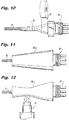
Figs. 9 and10 show the step of spirally wrapping heat resistant tape over a distal end portion of the outer protective sheath, the distal end portion of the tube and the two bifurcated core wires of linear detector cable, to define a transition area at each end of the cable; -
Fig. 11 shows the transition boot positioned over the transition area delineated by the spirally wrapped tape at each end of the assembly; and -
Fig. 12 illustrates the step of heat shrinking a transition boot over the transition region to encapsulate and protect the transition region. - Referring now to the drawings wherein like reference numerals identify similar structural features and/or elements of the subject matter disclosed herein, there is illustrated in
Fig. 1 a sheathed linear detection cable assembly having transition protection, which has been constructed in accordance with the method of the subject invention and is designated generally byreference numeral 10. - The sheathed linear
detection cable assembly 10 of the subject invention is particularly well suited for use in vehicles and is designed to operate at temperatures up to 260° C. The construction method and the components of thecable assembly 10 will be described in detail below with respect to the drawings. - Referring to
Fig. 2 , the construction method of the subject invention includes the initial step of preparing or otherwise cutting a pair ofelongated polymer tubes 12 to a predetermined length "L." Preferably, the polymer tubes are formed from PTFE or a similar heat resistant polymer material that will not shrink and will provide a smooth and lubricous transition structure for thecable assembly 10. Thepolymer tubes 12 are preferably cut to lengths of about 2.50 inches +/- 0.25 inches. - Then, heat resistant tape, having a given width "w" is wrapped around a distal end portion of each
polymer tube 12 to locally enlarge the outer diameter of the tube. This forms a stop orabutment surface 14 on the distal end portion of eachtube 12. Preferably, the step of wrapping heat resistant tape around the distal end portion of thepolymer tube 12 to form astop surface 14 involves wrapping at least two layers of tape around the distal end of thetube 12. - Preferably, the width "w" of the heat resistant tape and thus the
stop surface 14 is equal to about one-third of the length "L" of thetube 12. Suitable heat resistant tape includes, for example, 3M Glass Cloth Tape 361 or 3M Glass Cloth Electrical Tape 69, which are both commercially available from 3M Corporation of St. Paul, MN. These tapes have high temperature resistance, high adhesion and a very strong, abrasion resistant backing. - Once the
polymer tubes 12 are completed, the proximal end portion of eachtube 12 is inserted into an open end of a flexible protectiveouter sheath 16, as shown inFig. 3 , so that thestop surfaces 14 formed by the wrapped heat resistant tape abut against the ends of the protectiveouter sheath 16, as best seen inFig. 4 . This will ensure that thetubes 12 are properly positioned within thesheath 16. - Preferably, the protective
outer sheath 16 is formed from corrugated stainless steel or a similar flexible conduit and it has an inner diameter that is slightly greater than or equal to the outer diameter of thepolymer tubes 12. The metallicouter sheath 16 can vary in length depending upon the application in which it is intended to be used. - The method of the subject invention further includes the step of feeding a
linear detector cable 20 into theprotective sheath 16 through the distal end portion of one of thepolymer tubes 12, so that free end portion of thelinear detector cable 20 extends from each end of thesheath 16, as illustrated inFig. 5 . Thelinear detector cable 20 is comprised of two polymer coatedcore conductor wires 18a, 18b enclosed in anouter covering 22. The polymer coating on thewires 18a, 18b ofcable 20 is heat sensitive and designed to melt at a specific temperature, to effectuate a short indicating a fire along the length of the cable. Preferably, thecable 20 is positioned in theprotective sheath 16 so that theouter insulation 22 stops just before the end of thetube 12. - Once the
linear detector cable 20 is fed through thesheath 16, theouter covering 22 is stripped away from each end of the cable to expose the two polymer coatedcore wires 18a, 18b. Then, the polymer coating is stripped from eachwire 18a, 18b to expose about 0.25 inches of each core wire. A wire seal 24a, 24b and femaleterminal pin core wires 18a, 18b at each end of the cable, as shown inFig. 6 . The terminal pins 26a, 26b are preferably attached using a crimping tool or a similar joining technique. Thereafter, thebifurcated core wires 18a, 18b are bent so that the twoterminal pins - After the
terminal pins core wires 18a, 18b of thelinear detector cable 20, two heatshrinkable terminal boots sheath 16, with the thinner ends thereof arranged toward one another, as shown inFig. 7 . Thereafter, the pinnedcore wires 18a, 18b are installed in a weather-pack shroudedterminal connector 30, as shown inFig. 8 . More particularly, aterminal connector 30 is installed at both end of thelinear detector cable 20. Thecore wires 18a, 18b should be centered in the rear openings of theterminal connector 30. - Those skilled in the art will readily appreciate that the type of connector employed can vary depending up the application, and that the two connectors at the end of the assembly can be the same or different from one another. It should also be appreciated that the bending of the
bifurcated core wires 18a, 18b can vary depending on the type of connector employed. It should also be appreciated that the two terminal boots can be positioned on thesheath 16 after one of theterminal connectors 30 has been installed. Thus, the order of the construction steps described herein can vary by choice or preference. - Then, as shown in
Figs. 9 and10 , starting with one full width, a layer of heatresistant tape 32 is spirally wrapped over each distal end portion of the outerprotective sheath 16, proximal to the stop surfaces 14. The spiral wrapping continues over thestop surface 14, over the twobifurcated core wires 18a, 18b oflinear detector cable 20, up to the back of theterminal connector 30. This defines a transition region 34 at each end of thecable assembly 10. Thewires 18a, 18 should be maintained in a spread apart position when they are being wrapped, and the completion of the wrapping step, it should be verified that the core wires remain centered in the opening of theterminal connector 30. - A
transition boot tape 32 at each end of theassembly 10, as shown inFig. 11 , with the larger end of theboot 28a sliding over theconnector 30. Hot air from aheating device 36 is then directed at eachtransition boot - Importantly, the temperature of the air coming out of the heating device must be measure and adjusted so that the temperature of the heated air maintained in the range of 150°C and 170°C so as not to damage the heat sensitive polymer coating on the
core wires 18a, 18b of thelinear detection cable 20. Finally, the assembly is labeled at a location about 0.5 inches from the boot at one end of thecable assembly 10. Thefinished cable assembly 10 can then be wrapped into a coil configuration with loops of about 12 inches that can be secured together with black electrical tape. - It should be readily appreciated from the disclosure, that within the
finished cable assembly 10, thePTFE tubing 12 at each end of the protective sheath serves as chaff protection between the core-wires 18a, 18b of thelinear detector cable 20 and the outerprotective sheath 16, particularly at the open ends of theprotective sheath 16, where the edges are relatively sharp. Moreover, the PTFE tubing provides an assembly where there is not a direct bond between theprotective sheath 16 and thelinear detector cable 20. This will prevent the possibility of thedetector cable 20 being damaged. - While the subject invention has been shown and described with reference to preferred embodiments and methods of construction, those skilled in the art will readily appreciate that various changes and/or modifications may be made thereto without departing from the scope of the subject invention as defined by the appended claims.
Claims (15)
- A method for preventing chaffing between a linear detector cable and a protective outer sheath, comprising the steps of:a) preparing an elongated polymer tube having a predetermined length and outer diameter;b) wrapping heat resistant tape having a given width around a distal end portion of the polymer tube to locally enlarge the outer diameter of the tube; andc) inserting a proximal end portion of the polymer tube into an open end of a metallic protective sheath having a predetermined inner diameter that is slightly greater than or equal to the outer diameter of the tube, so that the heat resistant tape wrapped around the distal end portion of the tube abuts against the end of the protective sheath to acts as a stop surface, ensuring proper positioning of the tube within the sheath.
- A method according to Claim 1, further comprising the step of feeding a linear detector cable into the protective sheath through the distal end portion of the polymer tube.
- A method according to Claim 2, further comprising the step of installing a terminal connector to an end portion of the linear detector cable extending from the distal end portion of the polymer tube.
- A method according to Claim 3, further comprising the step of spirally wrapping a layer of heat resistant tape over an end portion of the protective sheath, the distal end portion of the tube and the linear detector cable, up to the back of the terminal connector, to define a transition area.
- A method according to Claim 4, further comprising the step of positioning a transition boot over the transition area delineated by the spirally wrapped tape.
- A method according to Claim 5, further comprising the step of heat shrinking the transition boot over the transition area delineated by the spirally wrapped tape.
- A method according to Claim 1, wherein the step of wrapping heat resistant tape around a distal end portion of the polymer tube involves wrapping at least two layers of tape around the distal end of the tube.
- A method according to Claim 1, wherein the step of wrapping heat resistant tape around a distal end portion of the polymer tube involves wrapping tape having a width that is about one third of the length of the tube.
- A method of constructing a sheathed linear detector cable with transition protection, comprising the steps of:a) providing an elongated metallic protective sheath having opposed open ends and a given inner diameter;b) providing a pair of elongated polymer tubes each having a given outer diameter that is slightly less than or equal to the inner diameter of the protective sheath;c) forming a stop surface on a distal end portion each polymer tube; andd) positioning a proximal end portion of one of the polymer tube into each open end of the protective sheath, so that the stop surface on the tube abuts against the end of the protective sheath to ensure proper positioning of that tube within the sheath.
- A method according to Claim 9, further comprising the step of feeding a linear detector cable into the protective sheath through the distal end portion of one of the polymer tubes.
- A method according to Claim 10, further comprising the step of installing a terminal connector to each of the end portions of the linear detector cable extending from the distal end portions of each of the polymer tubes.
- A method according to Claim 11, further comprising the step of spirally wrapping a layer of heat resistant tape over the end portion of the protective sheath, the distal end portion of the polymer tube and the portion of the linear detector cable extending from the tube, up to the back of the terminal connector, to define a transition area at each end of the protective sheath.
- A method according to Claim 12, further comprising the step of positioning transition boots over the transition areas delineated by the spirally wrapped tape at each end of the protective sheath.
- A method according to Claim 13, further comprising the step of heat shrinking the transition boots over the transition areas delineated by the spirally wrapped tape at each end of the protective sheath.
- A method according to Claim 11, wherein the step of forming a stop surface on a distal end portion each polymer tube involves wrapping at least two layers of heat resistant tape having a width that is about one third of the length of the tube, around the distal end portion of each tube to locally enlarge the outer diameter of each tube.
Applications Claiming Priority (1)
| Application Number | Priority Date | Filing Date | Title |
|---|---|---|---|
| US15/016,393 US10018512B2 (en) | 2016-02-05 | 2016-02-05 | Method for preventing chaffing between a linear detector cable and a protective outer sheath |
Publications (2)
| Publication Number | Publication Date |
|---|---|
| EP3203594A1 true EP3203594A1 (en) | 2017-08-09 |
| EP3203594B1 EP3203594B1 (en) | 2020-10-28 |
Family
ID=57965695
Family Applications (1)
| Application Number | Title | Priority Date | Filing Date |
|---|---|---|---|
| EP17153966.1A Active EP3203594B1 (en) | 2016-02-05 | 2017-01-31 | Method for preventing chaffing between a linear detector cable and a protective outer sheath |
Country Status (4)
| Country | Link |
|---|---|
| US (1) | US10018512B2 (en) |
| EP (1) | EP3203594B1 (en) |
| BR (1) | BR102016025489B1 (en) |
| CA (1) | CA2946057C (en) |
Families Citing this family (3)
| Publication number | Priority date | Publication date | Assignee | Title |
|---|---|---|---|---|
| CN108347028A (en) * | 2018-04-25 | 2018-07-31 | 福建通宇电缆有限公司 | A kind of cable winding device |
| DE102019131191A1 (en) * | 2019-11-19 | 2021-05-20 | Bayerische Motoren Werke Aktiengesellschaft | Housing cover for a battery housing with particle protection and heat protection, battery housing, traction battery and motor vehicle |
| DE102020104035A1 (en) | 2020-02-17 | 2021-08-19 | HARTING Electronics GmbH | Electrical connector with bend protection |
Citations (3)
| Publication number | Priority date | Publication date | Assignee | Title |
|---|---|---|---|---|
| US4431863A (en) * | 1981-10-08 | 1984-02-14 | Preformed Line Products Company | Protective boot for cables and method of applying same |
| NL1023812C2 (en) * | 2003-07-03 | 2005-01-04 | Filoform Bv | Sealing method for e.g. power cables and their connections, by winding tape with high viscosity material around exposed wires and covering tape with protection |
| CN201203925Y (en) * | 2008-05-16 | 2009-03-04 | 刘星 | Multifunctional liner temperature-sensing detector |
Family Cites Families (23)
| Publication number | Priority date | Publication date | Assignee | Title |
|---|---|---|---|---|
| DE7315770U (en) * | 1973-03-19 | 1973-09-06 | Costa Allan West Islip Ny | DEVICE FOR APPLYING COSMETIC PRODUCTS ON EYELASHES EYEBROWS OR THE LIKE. |
| US4867269A (en) * | 1987-06-30 | 1989-09-19 | Titeflex Corporation | Tuned self-damping convoluted conduit |
| US4912285A (en) | 1988-05-10 | 1990-03-27 | Nortek, Inc. | Anti-short bushing |
| US5163856A (en) * | 1989-10-20 | 1992-11-17 | Metcal, Inc. | Multipin connector |
| US5098319A (en) * | 1989-10-20 | 1992-03-24 | Metcal, Inc. | Multipin connector |
| US5280138A (en) | 1992-03-31 | 1994-01-18 | Virginia Plastics Company, Inc. | Cable protector |
| US5381511A (en) * | 1993-06-02 | 1995-01-10 | W. L. Gore & Associates, Inc. | Flexible electrically heatable hose |
| US5499528A (en) * | 1994-09-26 | 1996-03-19 | W. L. Gore & Associates, Inc. | Apparatus for measuring hot gas content |
| US5793293A (en) * | 1996-05-13 | 1998-08-11 | Furon Company | Temperature sensing system for over-heat detection |
| GB9713855D0 (en) * | 1997-06-30 | 1997-09-03 | Transradio Ltd | Coupling of optic fibres |
| US5944567A (en) * | 1997-10-31 | 1999-08-31 | Eveready Battery Company, Inc. | Heat-activated wire terminal assembly and method |
| US6713733B2 (en) * | 1999-05-11 | 2004-03-30 | Thermosoft International Corporation | Textile heater with continuous temperature sensing and hot spot detection |
| US20020164130A1 (en) * | 2001-05-07 | 2002-11-07 | Elkins Robert B. | Fiber optic module attachment including a fiber locating connector |
| CA2355972C (en) * | 2001-08-24 | 2009-11-17 | Shawcor Ltd. | Ionomer-insulated electrical connectors |
| US20040262025A1 (en) * | 2001-09-21 | 2004-12-30 | Konrad Brandt | Multi-part insulating cover |
| US8263866B2 (en) | 2004-09-16 | 2012-09-11 | Federal-Mogul World Wide, Inc. | Protection shield positioning assembly and positioning device therefor and method of use |
| CN101260902A (en) | 2008-04-24 | 2008-09-10 | 十堰达峰软轴有限公司 | Production process of protective sleeve of pulling cable |
| US9184517B1 (en) * | 2010-12-13 | 2015-11-10 | John E. Endacott | Crimpable insulated electrical connector |
| JP2014023166A (en) | 2012-07-12 | 2014-02-03 | Auto Network Gijutsu Kenkyusho:Kk | Electric wire protecting member and wiring harness |
| US9072501B2 (en) | 2013-03-15 | 2015-07-07 | Regents Of The University Of Minnesota | Micro-orifice surgical access system |
| JP6239882B2 (en) | 2013-07-12 | 2017-11-29 | 矢崎総業株式会社 | Wire harness |
| CN203871790U (en) | 2014-04-30 | 2014-10-08 | 比亚迪股份有限公司 | Wire harness fixing and protecting apparatus |
| US9827122B2 (en) * | 2015-05-04 | 2017-11-28 | Abbott Cardiovascular Systems Inc. | System for a catheter |
-
2016
- 2016-02-05 US US15/016,393 patent/US10018512B2/en active Active
- 2016-10-19 CA CA2946057A patent/CA2946057C/en active Active
- 2016-10-31 BR BR102016025489-2A patent/BR102016025489B1/en active IP Right Grant
-
2017
- 2017-01-31 EP EP17153966.1A patent/EP3203594B1/en active Active
Patent Citations (3)
| Publication number | Priority date | Publication date | Assignee | Title |
|---|---|---|---|---|
| US4431863A (en) * | 1981-10-08 | 1984-02-14 | Preformed Line Products Company | Protective boot for cables and method of applying same |
| NL1023812C2 (en) * | 2003-07-03 | 2005-01-04 | Filoform Bv | Sealing method for e.g. power cables and their connections, by winding tape with high viscosity material around exposed wires and covering tape with protection |
| CN201203925Y (en) * | 2008-05-16 | 2009-03-04 | 刘星 | Multifunctional liner temperature-sensing detector |
Also Published As
| Publication number | Publication date |
|---|---|
| US10018512B2 (en) | 2018-07-10 |
| CA2946057C (en) | 2024-03-12 |
| BR102016025489B1 (en) | 2022-10-11 |
| EP3203594B1 (en) | 2020-10-28 |
| BR102016025489A2 (en) | 2017-08-15 |
| US20170227401A1 (en) | 2017-08-10 |
| CA2946057A1 (en) | 2017-08-05 |
Similar Documents
| Publication | Publication Date | Title |
|---|---|---|
| EP3203594B1 (en) | Method for preventing chaffing between a linear detector cable and a protective outer sheath | |
| EP1857848B1 (en) | Optical cable shield layer connection | |
| CA2499184C (en) | Splice connection assembly using heat shrinkable tubing, metal sheathed heater using same, and method of making | |
| US6359226B1 (en) | Device and method for protecting and sealing exposed wires | |
| CN101685948B (en) | Method and member for retaining cable harness shape | |
| JP4767137B2 (en) | Seal wire waterproofing method and structure | |
| EP1049109B1 (en) | Heat shrinkable side entry cable jacket | |
| JP2009505016A (en) | End for high pressure / high temperature hose | |
| US20080289874A1 (en) | Spiral heater wire termination | |
| JP5402065B2 (en) | Shield wire terminal water-stop method and shield wire with terminal water-stop portion | |
| JPH11353952A (en) | Outer shield structure for electric wire | |
| US20200412120A1 (en) | Spliced shielded wire cable and method of manufacturing same | |
| JP5203112B2 (en) | Ground wire lead-out portion from power cable and power cable connecting portion provided with this ground wire lead-out portion | |
| US10720266B2 (en) | Shape retaining cable assembly | |
| EP0887807A1 (en) | Multiconductor electrical cable | |
| GB1585154A (en) | Heat recoverable article | |
| JP2000018450A (en) | Piping for embedding | |
| US11005211B2 (en) | Method for manufacturing cable with connector and cable with connector | |
| US20080254679A1 (en) | Electrical Device Comprising a Connecting Cable and Method for Producing Said Device | |
| AU2019282135B2 (en) | Cable with a fabric sleeve and its method of manufacture | |
| JP6285708B2 (en) | Protective tube | |
| CN108155488A (en) | A kind of electrical wire connection method | |
| JPS5883518A (en) | Device for preventing displacement of sheath of power cable | |
| JP2010129241A (en) | Structure for stopping water in end of shielding wire |
Legal Events
| Date | Code | Title | Description |
|---|---|---|---|
| PUAI | Public reference made under article 153(3) epc to a published international application that has entered the european phase |
Free format text: ORIGINAL CODE: 0009012 |
|
| STAA | Information on the status of an ep patent application or granted ep patent |
Free format text: STATUS: THE APPLICATION HAS BEEN PUBLISHED |
|
| AK | Designated contracting states |
Kind code of ref document: A1 Designated state(s): AL AT BE BG CH CY CZ DE DK EE ES FI FR GB GR HR HU IE IS IT LI LT LU LV MC MK MT NL NO PL PT RO RS SE SI SK SM TR |
|
| AX | Request for extension of the european patent |
Extension state: BA ME |
|
| STAA | Information on the status of an ep patent application or granted ep patent |
Free format text: STATUS: REQUEST FOR EXAMINATION WAS MADE |
|
| 17P | Request for examination filed |
Effective date: 20180209 |
|
| RBV | Designated contracting states (corrected) |
Designated state(s): AL AT BE BG CH CY CZ DE DK EE ES FI FR GB GR HR HU IE IS IT LI LT LU LV MC MK MT NL NO PL PT RO RS SE SI SK SM TR |
|
| STAA | Information on the status of an ep patent application or granted ep patent |
Free format text: STATUS: EXAMINATION IS IN PROGRESS |
|
| 17Q | First examination report despatched |
Effective date: 20180403 |
|
| REG | Reference to a national code |
Ref country code: DE Ref legal event code: R079 Ref document number: 602017026147 Country of ref document: DE Free format text: PREVIOUS MAIN CLASS: H01R0043280000 Ipc: H02G0001080000 |
|
| GRAP | Despatch of communication of intention to grant a patent |
Free format text: ORIGINAL CODE: EPIDOSNIGR1 |
|
| STAA | Information on the status of an ep patent application or granted ep patent |
Free format text: STATUS: GRANT OF PATENT IS INTENDED |
|
| RIC1 | Information provided on ipc code assigned before grant |
Ipc: H02G 1/08 20060101AFI20200430BHEP |
|
| INTG | Intention to grant announced |
Effective date: 20200525 |
|
| GRAS | Grant fee paid |
Free format text: ORIGINAL CODE: EPIDOSNIGR3 |
|
| GRAA | (expected) grant |
Free format text: ORIGINAL CODE: 0009210 |
|
| STAA | Information on the status of an ep patent application or granted ep patent |
Free format text: STATUS: THE PATENT HAS BEEN GRANTED |
|
| AK | Designated contracting states |
Kind code of ref document: B1 Designated state(s): AL AT BE BG CH CY CZ DE DK EE ES FI FR GB GR HR HU IE IS IT LI LT LU LV MC MK MT NL NO PL PT RO RS SE SI SK SM TR |
|
| REG | Reference to a national code |
Ref country code: GB Ref legal event code: FG4D |
|
| REG | Reference to a national code |
Ref country code: CH Ref legal event code: EP |
|
| REG | Reference to a national code |
Ref country code: AT Ref legal event code: REF Ref document number: 1329187 Country of ref document: AT Kind code of ref document: T Effective date: 20201115 |
|
| REG | Reference to a national code |
Ref country code: DE Ref legal event code: R096 Ref document number: 602017026147 Country of ref document: DE |
|
| REG | Reference to a national code |
Ref country code: IE Ref legal event code: FG4D |
|
| REG | Reference to a national code |
Ref country code: AT Ref legal event code: MK05 Ref document number: 1329187 Country of ref document: AT Kind code of ref document: T Effective date: 20201028 |
|
| REG | Reference to a national code |
Ref country code: NL Ref legal event code: MP Effective date: 20201028 |
|
| PG25 | Lapsed in a contracting state [announced via postgrant information from national office to epo] |
Ref country code: PT Free format text: LAPSE BECAUSE OF FAILURE TO SUBMIT A TRANSLATION OF THE DESCRIPTION OR TO PAY THE FEE WITHIN THE PRESCRIBED TIME-LIMIT Effective date: 20210301 Ref country code: RS Free format text: LAPSE BECAUSE OF FAILURE TO SUBMIT A TRANSLATION OF THE DESCRIPTION OR TO PAY THE FEE WITHIN THE PRESCRIBED TIME-LIMIT Effective date: 20201028 Ref country code: NL Free format text: LAPSE BECAUSE OF FAILURE TO SUBMIT A TRANSLATION OF THE DESCRIPTION OR TO PAY THE FEE WITHIN THE PRESCRIBED TIME-LIMIT Effective date: 20201028 Ref country code: NO Free format text: LAPSE BECAUSE OF FAILURE TO SUBMIT A TRANSLATION OF THE DESCRIPTION OR TO PAY THE FEE WITHIN THE PRESCRIBED TIME-LIMIT Effective date: 20210128 Ref country code: GR Free format text: LAPSE BECAUSE OF FAILURE TO SUBMIT A TRANSLATION OF THE DESCRIPTION OR TO PAY THE FEE WITHIN THE PRESCRIBED TIME-LIMIT Effective date: 20210129 Ref country code: FI Free format text: LAPSE BECAUSE OF FAILURE TO SUBMIT A TRANSLATION OF THE DESCRIPTION OR TO PAY THE FEE WITHIN THE PRESCRIBED TIME-LIMIT Effective date: 20201028 |
|
| REG | Reference to a national code |
Ref country code: LT Ref legal event code: MG4D |
|
| PG25 | Lapsed in a contracting state [announced via postgrant information from national office to epo] |
Ref country code: SE Free format text: LAPSE BECAUSE OF FAILURE TO SUBMIT A TRANSLATION OF THE DESCRIPTION OR TO PAY THE FEE WITHIN THE PRESCRIBED TIME-LIMIT Effective date: 20201028 Ref country code: BG Free format text: LAPSE BECAUSE OF FAILURE TO SUBMIT A TRANSLATION OF THE DESCRIPTION OR TO PAY THE FEE WITHIN THE PRESCRIBED TIME-LIMIT Effective date: 20210128 Ref country code: LV Free format text: LAPSE BECAUSE OF FAILURE TO SUBMIT A TRANSLATION OF THE DESCRIPTION OR TO PAY THE FEE WITHIN THE PRESCRIBED TIME-LIMIT Effective date: 20201028 Ref country code: PL Free format text: LAPSE BECAUSE OF FAILURE TO SUBMIT A TRANSLATION OF THE DESCRIPTION OR TO PAY THE FEE WITHIN THE PRESCRIBED TIME-LIMIT Effective date: 20201028 Ref country code: IS Free format text: LAPSE BECAUSE OF FAILURE TO SUBMIT A TRANSLATION OF THE DESCRIPTION OR TO PAY THE FEE WITHIN THE PRESCRIBED TIME-LIMIT Effective date: 20210228 Ref country code: AT Free format text: LAPSE BECAUSE OF FAILURE TO SUBMIT A TRANSLATION OF THE DESCRIPTION OR TO PAY THE FEE WITHIN THE PRESCRIBED TIME-LIMIT Effective date: 20201028 Ref country code: ES Free format text: LAPSE BECAUSE OF FAILURE TO SUBMIT A TRANSLATION OF THE DESCRIPTION OR TO PAY THE FEE WITHIN THE PRESCRIBED TIME-LIMIT Effective date: 20201028 |
|
| PG25 | Lapsed in a contracting state [announced via postgrant information from national office to epo] |
Ref country code: HR Free format text: LAPSE BECAUSE OF FAILURE TO SUBMIT A TRANSLATION OF THE DESCRIPTION OR TO PAY THE FEE WITHIN THE PRESCRIBED TIME-LIMIT Effective date: 20201028 |
|
| REG | Reference to a national code |
Ref country code: DE Ref legal event code: R097 Ref document number: 602017026147 Country of ref document: DE |
|
| PG25 | Lapsed in a contracting state [announced via postgrant information from national office to epo] |
Ref country code: SK Free format text: LAPSE BECAUSE OF FAILURE TO SUBMIT A TRANSLATION OF THE DESCRIPTION OR TO PAY THE FEE WITHIN THE PRESCRIBED TIME-LIMIT Effective date: 20201028 Ref country code: RO Free format text: LAPSE BECAUSE OF FAILURE TO SUBMIT A TRANSLATION OF THE DESCRIPTION OR TO PAY THE FEE WITHIN THE PRESCRIBED TIME-LIMIT Effective date: 20201028 Ref country code: SM Free format text: LAPSE BECAUSE OF FAILURE TO SUBMIT A TRANSLATION OF THE DESCRIPTION OR TO PAY THE FEE WITHIN THE PRESCRIBED TIME-LIMIT Effective date: 20201028 Ref country code: LT Free format text: LAPSE BECAUSE OF FAILURE TO SUBMIT A TRANSLATION OF THE DESCRIPTION OR TO PAY THE FEE WITHIN THE PRESCRIBED TIME-LIMIT Effective date: 20201028 Ref country code: EE Free format text: LAPSE BECAUSE OF FAILURE TO SUBMIT A TRANSLATION OF THE DESCRIPTION OR TO PAY THE FEE WITHIN THE PRESCRIBED TIME-LIMIT Effective date: 20201028 Ref country code: CZ Free format text: LAPSE BECAUSE OF FAILURE TO SUBMIT A TRANSLATION OF THE DESCRIPTION OR TO PAY THE FEE WITHIN THE PRESCRIBED TIME-LIMIT Effective date: 20201028 |
|
| PG25 | Lapsed in a contracting state [announced via postgrant information from national office to epo] |
Ref country code: MC Free format text: LAPSE BECAUSE OF FAILURE TO SUBMIT A TRANSLATION OF THE DESCRIPTION OR TO PAY THE FEE WITHIN THE PRESCRIBED TIME-LIMIT Effective date: 20201028 Ref country code: DK Free format text: LAPSE BECAUSE OF FAILURE TO SUBMIT A TRANSLATION OF THE DESCRIPTION OR TO PAY THE FEE WITHIN THE PRESCRIBED TIME-LIMIT Effective date: 20201028 |
|
| REG | Reference to a national code |
Ref country code: CH Ref legal event code: PL |
|
| PLBE | No opposition filed within time limit |
Free format text: ORIGINAL CODE: 0009261 |
|
| STAA | Information on the status of an ep patent application or granted ep patent |
Free format text: STATUS: NO OPPOSITION FILED WITHIN TIME LIMIT |
|
| PG25 | Lapsed in a contracting state [announced via postgrant information from national office to epo] |
Ref country code: LU Free format text: LAPSE BECAUSE OF NON-PAYMENT OF DUE FEES Effective date: 20210131 |
|
| 26N | No opposition filed |
Effective date: 20210729 |
|
| REG | Reference to a national code |
Ref country code: BE Ref legal event code: MM Effective date: 20210131 |
|
| PG25 | Lapsed in a contracting state [announced via postgrant information from national office to epo] |
Ref country code: IT Free format text: LAPSE BECAUSE OF FAILURE TO SUBMIT A TRANSLATION OF THE DESCRIPTION OR TO PAY THE FEE WITHIN THE PRESCRIBED TIME-LIMIT Effective date: 20201028 Ref country code: AL Free format text: LAPSE BECAUSE OF FAILURE TO SUBMIT A TRANSLATION OF THE DESCRIPTION OR TO PAY THE FEE WITHIN THE PRESCRIBED TIME-LIMIT Effective date: 20201028 |
|
| PG25 | Lapsed in a contracting state [announced via postgrant information from national office to epo] |
Ref country code: CH Free format text: LAPSE BECAUSE OF NON-PAYMENT OF DUE FEES Effective date: 20210131 Ref country code: SI Free format text: LAPSE BECAUSE OF FAILURE TO SUBMIT A TRANSLATION OF THE DESCRIPTION OR TO PAY THE FEE WITHIN THE PRESCRIBED TIME-LIMIT Effective date: 20201028 Ref country code: LI Free format text: LAPSE BECAUSE OF NON-PAYMENT OF DUE FEES Effective date: 20210131 |
|
| PG25 | Lapsed in a contracting state [announced via postgrant information from national office to epo] |
Ref country code: IE Free format text: LAPSE BECAUSE OF NON-PAYMENT OF DUE FEES Effective date: 20210131 |
|
| PG25 | Lapsed in a contracting state [announced via postgrant information from national office to epo] |
Ref country code: IS Free format text: LAPSE BECAUSE OF FAILURE TO SUBMIT A TRANSLATION OF THE DESCRIPTION OR TO PAY THE FEE WITHIN THE PRESCRIBED TIME-LIMIT Effective date: 20210228 |
|
| PG25 | Lapsed in a contracting state [announced via postgrant information from national office to epo] |
Ref country code: BE Free format text: LAPSE BECAUSE OF NON-PAYMENT OF DUE FEES Effective date: 20210131 |
|
| PG25 | Lapsed in a contracting state [announced via postgrant information from national office to epo] |
Ref country code: HU Free format text: LAPSE BECAUSE OF FAILURE TO SUBMIT A TRANSLATION OF THE DESCRIPTION OR TO PAY THE FEE WITHIN THE PRESCRIBED TIME-LIMIT; INVALID AB INITIO Effective date: 20170131 |
|
| PG25 | Lapsed in a contracting state [announced via postgrant information from national office to epo] |
Ref country code: CY Free format text: LAPSE BECAUSE OF FAILURE TO SUBMIT A TRANSLATION OF THE DESCRIPTION OR TO PAY THE FEE WITHIN THE PRESCRIBED TIME-LIMIT Effective date: 20201028 |
|
| P01 | Opt-out of the competence of the unified patent court (upc) registered |
Effective date: 20230603 |
|
| PGFP | Annual fee paid to national office [announced via postgrant information from national office to epo] |
Ref country code: GB Payment date: 20231219 Year of fee payment: 8 |
|
| PGFP | Annual fee paid to national office [announced via postgrant information from national office to epo] |
Ref country code: FR Payment date: 20231219 Year of fee payment: 8 |
|
| PG25 | Lapsed in a contracting state [announced via postgrant information from national office to epo] |
Ref country code: MK Free format text: LAPSE BECAUSE OF FAILURE TO SUBMIT A TRANSLATION OF THE DESCRIPTION OR TO PAY THE FEE WITHIN THE PRESCRIBED TIME-LIMIT Effective date: 20201028 |
|
| PGFP | Annual fee paid to national office [announced via postgrant information from national office to epo] |
Ref country code: DE Payment date: 20231219 Year of fee payment: 8 |