EP3203544B1 - Akkublock mit mehreren akkuzellen, verwendung eines akkublocks in einem elektrischen gerät und verfahren zur herstellung eines akkublocks - Google Patents
Akkublock mit mehreren akkuzellen, verwendung eines akkublocks in einem elektrischen gerät und verfahren zur herstellung eines akkublocks Download PDFInfo
- Publication number
- EP3203544B1 EP3203544B1 EP17000144.0A EP17000144A EP3203544B1 EP 3203544 B1 EP3203544 B1 EP 3203544B1 EP 17000144 A EP17000144 A EP 17000144A EP 3203544 B1 EP3203544 B1 EP 3203544B1
- Authority
- EP
- European Patent Office
- Prior art keywords
- battery
- battery block
- battery cells
- block according
- polyethylene terephthalate
- Prior art date
- Legal status (The legal status is an assumption and is not a legal conclusion. Google has not performed a legal analysis and makes no representation as to the accuracy of the status listed.)
- Not-in-force
Links
Images


Classifications
-
- H—ELECTRICITY
- H01—ELECTRIC ELEMENTS
- H01M—PROCESSES OR MEANS, e.g. BATTERIES, FOR THE DIRECT CONVERSION OF CHEMICAL ENERGY INTO ELECTRICAL ENERGY
- H01M50/00—Constructional details or processes of manufacture of the non-active parts of electrochemical cells other than fuel cells, e.g. hybrid cells
- H01M50/10—Primary casings; Jackets or wrappings
- H01M50/116—Primary casings; Jackets or wrappings characterised by the material
- H01M50/124—Primary casings; Jackets or wrappings characterised by the material having a layered structure
-
- H—ELECTRICITY
- H01—ELECTRIC ELEMENTS
- H01M—PROCESSES OR MEANS, e.g. BATTERIES, FOR THE DIRECT CONVERSION OF CHEMICAL ENERGY INTO ELECTRICAL ENERGY
- H01M50/00—Constructional details or processes of manufacture of the non-active parts of electrochemical cells other than fuel cells, e.g. hybrid cells
- H01M50/10—Primary casings; Jackets or wrappings
- H01M50/102—Primary casings; Jackets or wrappings characterised by their shape or physical structure
- H01M50/107—Primary casings; Jackets or wrappings characterised by their shape or physical structure having curved cross-section, e.g. round or elliptic
-
- H—ELECTRICITY
- H01—ELECTRIC ELEMENTS
- H01M—PROCESSES OR MEANS, e.g. BATTERIES, FOR THE DIRECT CONVERSION OF CHEMICAL ENERGY INTO ELECTRICAL ENERGY
- H01M50/00—Constructional details or processes of manufacture of the non-active parts of electrochemical cells other than fuel cells, e.g. hybrid cells
- H01M50/10—Primary casings; Jackets or wrappings
- H01M50/116—Primary casings; Jackets or wrappings characterised by the material
- H01M50/121—Organic material
-
- H—ELECTRICITY
- H01—ELECTRIC ELEMENTS
- H01M—PROCESSES OR MEANS, e.g. BATTERIES, FOR THE DIRECT CONVERSION OF CHEMICAL ENERGY INTO ELECTRICAL ENERGY
- H01M50/00—Constructional details or processes of manufacture of the non-active parts of electrochemical cells other than fuel cells, e.g. hybrid cells
- H01M50/50—Current conducting connections for cells or batteries
- H01M50/543—Terminals
- H01M50/547—Terminals characterised by the disposition of the terminals on the cells
- H01M50/548—Terminals characterised by the disposition of the terminals on the cells on opposite sides of the cell
-
- H—ELECTRICITY
- H01—ELECTRIC ELEMENTS
- H01M—PROCESSES OR MEANS, e.g. BATTERIES, FOR THE DIRECT CONVERSION OF CHEMICAL ENERGY INTO ELECTRICAL ENERGY
- H01M50/00—Constructional details or processes of manufacture of the non-active parts of electrochemical cells other than fuel cells, e.g. hybrid cells
- H01M50/50—Current conducting connections for cells or batteries
- H01M50/543—Terminals
- H01M50/552—Terminals characterised by their shape
- H01M50/559—Terminals adapted for cells having curved cross-section, e.g. round, elliptic or button cells
-
- Y—GENERAL TAGGING OF NEW TECHNOLOGICAL DEVELOPMENTS; GENERAL TAGGING OF CROSS-SECTIONAL TECHNOLOGIES SPANNING OVER SEVERAL SECTIONS OF THE IPC; TECHNICAL SUBJECTS COVERED BY FORMER USPC CROSS-REFERENCE ART COLLECTIONS [XRACs] AND DIGESTS
- Y02—TECHNOLOGIES OR APPLICATIONS FOR MITIGATION OR ADAPTATION AGAINST CLIMATE CHANGE
- Y02E—REDUCTION OF GREENHOUSE GAS [GHG] EMISSIONS, RELATED TO ENERGY GENERATION, TRANSMISSION OR DISTRIBUTION
- Y02E60/00—Enabling technologies; Technologies with a potential or indirect contribution to GHG emissions mitigation
- Y02E60/10—Energy storage using batteries
Definitions
- the invention relates to a battery pack with a plurality of rechargeable battery cells according to the features of patent claim 1, the use of a rechargeable battery block in an electrical device according to the features of patent claim 9 and a method for producing a rechargeable battery block according to the features of patent claim 10.
- Medical devices are conventionally sterilized or disinfected using either heat, such as that provided by steam, or a chemical in the liquid, gaseous, or vapor state. Before sterilization or disinfection, the equipment to be treated is usually first cleaned and then sterilized or disinfected. After sterilization or disinfection with a liquid, germicidal chemical, purified water is used to rinse the instruments, and then the instruments are dried.
- a battery drilling machine has the problem that the battery pack used usually does not withstand the temperature, humidity and pressure prevailing in a sterilization. Therefore, in medical technology usually unsterilized battery packs are installed in sterilized electrical medical devices. However, it can still lead to undesirable contamination.
- Out DE 8907055 A1 discloses an electrical medical device with a battery pack which can withstand the environmental conditions of sterilization.
- the accumulator block described is a conventional accumulator block which is wrapped in a first layer with a polysulfone film and in a second layer with a polyethylene ether content.
- a third layer forms a shrink tube and a fourth layer is formed by a potting compound.
- an object of the invention to provide an improved battery pack with improved temperature resistance, improved pressure resistance and improved resistance to moisture in the sterilization process. Another object is to specify a method of use and a method for producing such a battery pack.
- the battery pack according to the invention comprises a plurality of commercial battery cells. These multiple battery cells are surrounded by a sheath, wherein the sheath comprises a layer of polyethylene terephthalate, a shrink tube and a potting compound. According to the invention, each individual battery cell is surrounded by a polyimide layer.
- the envelope or parts of the envelope can serve as a housing of the battery pack.
- the potting compound may represent the housing of the battery pack.
- the battery cartridge according to the invention thus consists of a plurality of battery cells, each coated with a polyimide layer, which form an array of battery cells coated with a polyimide layer. This array of battery cells coated with a polyimide layer is wrapped, wrapped, surrounded or coated with a layer of polyethylene terephthalate.
- a commercial rechargeable secondary cell e.g. a lithium-ion secondary battery or lithium-based secondary battery (e.g., lithium-sulfur secondary battery), nickel cadmium secondary battery, nickel metal hydride secondary battery, nickel zinc secondary battery or alkaline manganese secondary battery.
- a lithium-ion secondary battery or lithium-based secondary battery e.g., lithium-sulfur secondary battery
- nickel cadmium secondary battery e.g., lithium-sulfur secondary battery
- nickel metal hydride secondary battery e.g., nickel metal hydride secondary battery
- nickel zinc secondary battery e.g., alkaline manganese secondary battery.
- other types of rechargeable batteries can be used.
- the battery cells can have commercially available sizes, such as AA or AAA types.
- Polyethylene terephthalate also referred to as PET or PEPT, is understood as meaning a thermoplastic polymer produced by polycondensation.
- Polyethylene terephthalate has a variety of uses and is used, inter alia, for the production of plastic bottles (PET bottles), films and textile fibers.
- Polyimides are generally understood to mean plastics whose most important structural feature is the imide group. These include u. a. Polysuccinimide (PSI), polybismaleimide (PBMI), polybenzimidazole (PBI) and polyoxadiazobenzimidazole (PBO), polyimide sulfone (PISO) and polymethacrylimide (PMI).
- PSI Polysuccinimide
- PBMI polybismaleimide
- PBI polybenzimidazole
- PBO polyoxadiazobenzimidazole
- PISO polyimide sulfone
- PMI polymethacrylimide
- the polyimide layer may be a polyimide film with thermosetting silicone adhesive, the film being wound around each individual battery cell at least once. This ensures that the polyimide film does not detach from the battery cell during temperature fluctuations.
- the use of the silicone adhesive ensures that there is no release of unwanted gases.
- the plurality of rechargeable battery cells are interconnected within the enclosure in a predetermined arrangement.
- the multiple battery cells are connected in series with each other.
- the total rated voltage of the rechargeable battery pack is 15 V on.
- the interconnected arrangement of the multiple battery cells is expediently provided with a silicone cable strand for the cathode conductor (negative pole) and a silicone cable strand for the anode conductor (positive pole). These two silicone cable strands are expediently led outwards and are used to connect a charger.
- the layer of polyethylene terephthalate is formed from a polyethylene terephthalate film which is wound around the plurality of battery cells at least ten times.
- the polyethylene terephthalate film is not wound around a single battery cell, but to the entire arrangement of the battery cells interconnected with each other.
- the polyethylene terephthalate film has very good thermal insulation properties, whereby the enveloped battery cells are protected from the high temperatures during the sterilization process. This effect is due to the at least 10 windings. Due to the residual air fraction located between the individual windings, an air cushion is formed between the individual windings, which reinforces the insulating property.
- the at least 10 windings are formed by a corresponding number of layers of a polyethylene terephthalate film.
- the thickness of the layer of polyethylene terephthalate is greater than 1 mm. This ensures that the enveloped battery cells are protected against excessive temperature during the entire sterilization process.
- a temperature sensor is arranged within the enclosure, with silicone cable strands leading to the outside for connection to a safety circuit. With this temperature sensor, it is possible to monitor the charging process of the multiple battery cells. When a predetermined temperature of the battery cells during charging is exceeded, the charging process can be interrupted via an electrical control circuit, to which the temperature sensor can be connected, in order to prevent overheating of the battery cells.
- the temperature sensor is located within the enclosure.
- the polyethylene terephthalate layer thus surrounds the multiple battery cells and the temperature sensor.
- the temperature sensor is e.g. attached to one or more battery cells, e.g. by silicone glue.
- the shrink tube is made of silicone.
- the heat-shrinkable tube envelops the layer of polyethylene terephthalate enveloped arrangement of interconnected battery cells.
- the shrink tube essentially serves to fix the layer of polyethylene terephthalate.
- the potting compound is a cold-polymerizing plastic.
- An advantage of cold-curing plastic is its resistance to breakage. Another advantage is that cold-polymerizing plastic in medical technology is already used for implant work and as a denture plastic. The battery cartridge according to the invention is thus surrounded by a plastic, which is already established in medical technology. The risk of dangerous contamination by the battery pack can thus be almost eliminated.
- the electrical appliance may conveniently be a medical appliance comprising a housing with an electric machine, e.g. a cordless drill.
- the electrical device can also be another device that can be operated on battery power.
- the step a) of providing a plurality of individual battery cells may in particular comprise the removal of a film surrounding the conventional, commercial battery cells with advertising imprints.
- Fig. 1 shows the exemplary schematic structure of a battery cartridge according to the invention.
- the battery pack 100 is constructed by way of example with 5 battery cells 1 and has an enclosure 101.
- the battery cartridge 100 may also consist of several or fewer battery cells 1.
- the sheath 101 is formed from a polyethylene terephthalate film 3, a shrink tube 4 and a potting compound 2.
- the sheath 101 surrounds the 5 battery cells 1 completely.
- Each individual battery cell 1 is surrounded by a polyimide film 5 with thermosetting silicone adhesive.
- Each battery cell 1 has an anode 10 and a cathode 11.
- the anodes 10 and cathodes 11 of the individual battery cells 1 are in Fig. 1 example interconnected from right to left in a series circuit 12 with each other.
- the anode 10 (positive pole) of the left battery cell 1 is connected to an anode conductor 9.
- This anode conductor 9 is connected to an interface (not shown) outside of the battery pack 100 for connection to a charger (not shown).
- the cathode 11 (negative pole) of the right battery cell 1 is connected to a cathode conductor 6.
- This cathode arrester 6 is connected to an interface (not shown) outside of the battery cartridge 100 for connection to a charger (not shown).
- a temperature sensor 7 is attached by way of example.
- This temperature sensor 7 has silicone strands 8, which are connected to an interface (not shown) outside of the battery pack 100 for connection to a control device (not shown).
- the arrangement of the battery cells 1 connected to one another are enveloped by a film 3 of polyethylene terephthalate.
- This film 3 is at least ten times (not shown) wrapped around the interconnected arrangement of the example 5 Akkuzellen 1.
- This arrangement further surrounds a shrink tube made of silicone.
- a potting compound 2 made of a cold-polymerizing plastic is present. From Akkublock 100 thus protrude only the Anodenableiter 9, the Kathodenableiter 6 and the silicone strands 8 of the temperature sensor. 7
- Fig. 2 shows an example of a sectional view of a medical device with a battery cartridge according to the invention.
- the medical device 200 is an example of a cordless drill.
- the battery drilling machine has a housing 23 for receiving a bearing 22 for the drive shaft 27 of the drill (not shown). Further, in the housing 23, a gear 21 is provided which connects the shaft 27 and an electric motor 24.
- a recess for the battery pack 100 is provided in the handle of Akkubohrmaschine, ie in the lower region of the housing 23, a recess for the battery pack 100 is provided.
- an interface 26 for connection to a charger (not shown) is present, which are connected to the anode conductor 9 and the cathode conductor 6 of the battery cartridge 100.
- an electronic circuit / control circuit 25 is still present in the housing 23 of the battery drill, which via a switch 20, the cordless drill 200 on or off, adjusts the speed of the electric motor or stops the charging process due to a temperature detected by the temperature sensor.
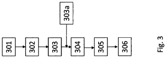
- Fig. 3 shows the sequence of a method according to the invention.
- step 301 a plurality of individual battery cells 1 are provided. Suitably, these rechargeable battery cells 1 are already freed in step 301 of the plastic film, which surrounds the commercial battery cells 1 and is provided with various manufacturer's information.
- step 302 a polyimide layer is placed around each individual battery cell 1, specifically in the form of a polyimide film, which is wound around the individual battery cell 1 at least once.
- the individual battery cells 1 are interconnected in a series connection. The interconnection is advantageously carried out by means of silicone strands, which are soldered to the anodes or cathodes of the individual battery cells 1.
- a temperature sensor can be attached to the previously produced arrangement; this temperature sensor is expediently glued to a battery cell with silicone adhesive.
- a layer of polyethylene terephthalate is applied around the plurality of battery cells connected to one another, specifically in the form of a polyethylene terephthalate film, which is wound at least ten times around the battery cells 1 of the battery cartridge 100.
- a shrink tube is applied to the layer of polyethylene terephthalate or the windings of the polyethylene terephthalate film. This shrink tubing is shrunk by heat input until it rests completely on the arrangement of the battery cells.
- the assembly is surrounded with a cold-polymerizing plastic. For this purpose, the arrangement is placed in a casting mold in which the assembly produced in the previous steps is completely potted.
Landscapes
- Chemical & Material Sciences (AREA)
- Chemical Kinetics & Catalysis (AREA)
- Electrochemistry (AREA)
- General Chemical & Material Sciences (AREA)
- Battery Mounting, Suspending (AREA)
Description
- Die Erfindung betrifft einen Akkublock mit mehreren Akkuzellen gemäß den Merkmalen des Patentanspruchs 1, die Verwendung eines Akkublocks in einem elektrischen Gerät gemäß den Merkmalen des Patentanspruchs 9 sowie ein Verfahren zur Herstellung eines Akkublocks gemäß den Merkmalen des Patentanspruchs 10.
- Medizinische Geräte werden in herkömmlicher Weise sterilisiert oder desinfiziert, indem entweder Wärme verwendet wird, wie sie beispielsweise durch Dampf zur Verfügung gestellt wird, oder ein chemischer Stoff in flüssigem, gasförmigem oder dampfförmigem Zustand. Vor einer Sterilisierung oder Desinfektion werden die zu behandelnden Geräte normalerweise zunächst gereinigt und dann sterilisiert oder desinfiziert. Nach einer Sterilisation oder Desinfektion mit einem flüssigen, keimtötenden chemischen Stoff wird gereinigtes Wasser verwendet, um die Instrumente zu spülen, und anschließend werden die Instrumente getrocknet.
- Bei elektrischen medizinischen Geräten, wie z.B. einer Akkubohrmaschine ergibt sich das Problem, dass der verwendete Akkublock in der Regel die Temperatur, Feuchtigkeit und Drucke, welche bei einer Sterilisation vorherrschen nicht standhält. Daher werden in der Medizintechnik üblicherweise nicht-sterilisierte Akkublocks in sterilisierte elektrische medizinische Geräte eingebaut. Hierbei kann es aber dennoch zu einer unerwünschten Kontaminationen führen.
- In
DE 699 29 674 T3 undUS2014/0342204A1 wird der durch mehrere Schichten gebildete Aufbau des Gehäuses von herkömmlichen Akkuzellen offenbart. - Aus
DE 8907055 A1 ist ein elektrisches medizinisches Gerät mit einem Akkublock offenbart, welcher die Umgebungsbedingungen bei einer Sterilisation aushält. Bei dem beschriebenen Akkublock handelt es sich um einen herkömmlichen Akkublock, welcher in einer ersten Schicht mit einer Polysulfon-Folie und in einer zweiten Schicht mit einer Polyäthylentherathalt umwickelt ist. Eine dritte Schicht bildet ein Schrumpfschlauch und eine vierte Schicht wird von einer Vergussmasse gebildet. - Ausgehend von dem Stand der Technik ist es eine Aufgabe der Erfindung einen verbesserten Akkublock anzugeben mit einer verbesserten Temperaturbeständigkeit, einer verbesserten Druckbeständigkeit und einer verbesserten Beständigkeit gegen Feuchtigkeit beim Sterilisationsprozess. Weitere Aufgabe bestehen in der Angabe eines Verwendungsverfahrens und eines Verfahrens zur Herstellung eines solchen Akkublocks.
- Diese Aufgaben werden mit den unabhängigen Ansprüchen 1, 9 und 10 gelöst. Vorteilhafte Ausführungen sind Gegenstand von Unteransprüchen.
- Der erfindungsgemäße Akkublock umfasst mehrere handelsübliche Akkuzellen. Diese mehreren Akkuzellen sind von einer Umhüllung umgeben, wobei die Umhüllung eine Schicht aus Polyethylenterephthalat, einen Schrumpfschlauch und eine Vergussmasse aufweist. Gemäß der Erfindung ist jede einzelne Akkuzelle mit einer Polyimideschicht umgeben. Die Umhüllung bzw. Teile der Umhüllung können dabei als Gehäuse des Akkublocks dienen. Insbesondere kann die Vergussmasse das Gehäuse des Akkublocks darstellen. Mit anderen Worten, der erfindungsgemäße Akkublock besteht somit aus mehreren, jeweils mit einer Polyimideschicht überzogenen Akkuzellen, welche eine Anordnung von mit einer Polyimideschicht überzogenen Akkuzellen bilden. Diese Anordnung von mit einer Polyimideschicht überzogenen Akkuzellen ist mit einer Schicht aus Polyethylenterephthalat umhüllt, umwickelt, umgeben oder überzogen.
- Unter einer Akkuzelle wird im Weiteren eine handelsübliche wiederaufladbare Sekundärzelle, z.B. ein Lithium-Ionen-Akkumulator oder auf Lithium basierender Akkumulator (z.B. Lithium-Schwefel-Akkumulator), Nickel-Cadmium.Akkumulator, Nickel-Metallhydrid-Akkumulator, Nickel-Zink-Akkumulator oder Alkali-Mangan-Akkumulator verstanden. Selbstverständlich können auch andere Typen von wiederaufladbare Akkumulatoren Verwendung finden.
- Die Akkuzellen können handelsübliche Größen, wie z.B. AA- oder AAA-Typen aufweisen.
- Unter Polyethylenterephthalat, auch als PET oder PEPT bezeichnet, wird ein durch Polykondensation hergestellter thermoplastischer Kunststoff verstanden. Polyethylenterephthalat hat vielfältige Einsatzbereiche und wird unter anderem zur Herstellung von Kunststoffflaschen (PET-Flaschen), Folien und Textilfasern verwendet.
- Unter Polyimide werden im allgemeinen Kunststoffe verstanden, deren wichtigstes Strukturmerkmal die Imidgruppe ist. Dazu gehören u. a. Polysuccinimid (PSI), Polybismaleinimid (PBMI), Polybenzimidazol (PBI) und Polyoxadiazobenzimidazol (PBO), Polyimidsulfon (PISO) und Polymethacrylimid (PMI).
- Mit der Polyimideschicht um die einzelnen Akkuzellen wird eine sehr hohe Wärmebeständigkeit von mehr als 200°C erreicht. Ferner wird dadurch erreicht, dass bei den hohen Temperaturen während des Sterilisationsprozesses keine unerwünschten Gase freigesetzt werden. Schließlich wird durch den Einsatz der Polyimideschicht um jede einzelne Akkuzelle gewährleistet, dass es zwischen den Akkuzellen zu keinem Kurzschluss kommen kann.
- Die Polyimideschicht kann eine Polyimide-Folie mit wärmehärtendem Silikonklebstoff sein, wobei die Folie um jede einzelne Akkuzelle mindestens einmal gewickelt ist. Damit ist sichergestellt, dass sich die Polyimide-Folie sich bei Temperaturschwankungen nicht von der Akkuzelle ablöst. Durch die Verwendung des Silikonklebers ist sichergestellt, dass es zu keinem Freisetzen von unerwünschten Gasen kommt.
- In einer Ausführungsform der Erfindung sind die mehreren Akkuzellen innerhalb der Umhüllung in einer vorgegebenen Anordnung miteinander verschaltet. Zweckmäßig sind die mehreren Akkuzellen in einer Serienschaltung miteinander verschaltet. So ist es möglich, bei Verwendung mehrerer Akkuzellen mit vorgegebener Nennspannung einen Akkublock mit einer entsprechenden Summen-Nennspannung zu erzeugen. Bei Verwendung von z.B. 10 wieder aufladbaren Alkali-Mangan-Akkuzellen mit einer Nennspannung von jeweils 1,5 V beträgt die Gesamt-Nennspannung des Akkkublocks 15 V auf. Die verschaltete Anordnung von den mehreren Akkuzellen ist zweckmäßig mit einer Silikonkabellitze für den Kathodenableiter (Minuspol) und einer Silikonkabellitze für den Anodenableiter (Pluspol) versehen. Diese beiden Silikonkabellitzen sind zweckmäßig nach außen geführt und dienen dem Anschluss eines Ladegeräts.
- In einer weiteren Ausführungsform der Erfindung ist die Schicht aus Polyethylen-terephthalat aus einer Polyethylenterephthalat-Folie gebildet, welche mindestens zehnmal um die mehreren Akkuzellen gewickelt ist. Es sei hier darauf hingewiesen, dass die Polyethylenterephthalat-Folie nicht um eine einzelne Akkuzelle gewickelt ist, sondern um die gesamte Anordnung der miteinander verschalteten Akkuzellen. Die Polyethylen-terephthalat-Folie weist sehr gute Wärmeisolationseigenschaften auf, wodurch die umhüllten Akkuzellen vor den hohen Temperaturen beim Sterilisationsprozess geschützt werden. Dieser Effekt wird durch die mindestens 10 Wicklungen. Aufgrund des sich zwischen den einzelnen Wicklungen befindlichen Restluftanteils wird zwischen den einzelnen Wicklungen ein Luftpolster gebildet, welches die Isolierungseigenschaft noch verstärkt. Selbstverständlich ist es möglich, dass die mindestens 10 Wicklungen durch eine entsprechende Anzahl von Lagen einer Polyethylenterephthalat-Folie gebildet sind.
- In einer weiteren Ausführungsform der Erfindung ist die Dicke der Schicht aus Polyethylenterephthalat größer als 1 mm. Damit ist sichergestellt, dass die umhüllten Akkuzellen während des gesamten Sterilisationsprozesses vor zu hoher Temperatur geschützt sind.
- In einer weiteren Ausführungsform der Erfindung ist innerhalb der Umhüllung ein Temperatursensor angeordnet, mit nach außen führenden Silikonkabellitzen zum Anschließen an eine Sicherheitsschaltung. Mit diesem Temperatursensor ist es möglich, den Ladevorgang der mehreren Akkuzellen zu überwachen. Bei Überschreiten einer vorgegebenen Temperatur der Akkuzellen beim Ladevorgang kann über eine elektrische Steuerschaltung, an welche der Temperatursensor anschließbar ist, der Ladevorgang abgebrochen werden, um ein Überhitzen der Akkuzellen zu verhindern.
- Zweckmäßig befindet sich Temperatursensor innerhalb der Umhüllung. Mit anderen Worten, die Schicht aus Polyethylenterephthalat umgibt somit die mehreren Akkuzellen und den Temperatursensor. Hierzu ist der Temperatursensor z.B. an einer oder mehreren Akkuzellen befestigt, z.B. mittels Silikonkleber.
- In einer weiteren Ausführungsform der Erfindung ist der Schrumpfschlauch aus Silikon gefertigt. Der Schrumpfschlauch umhüllt die mit der Schicht aus Polyethylen-terephthalat umhüllte Anordnung von miteinander verschalteten Akkuzellen. Der Schrumpfschlauch dient im Wesentlichen der Fixierung der Schicht aus Polyethylen-terephthalat.
- In einer weiteren Ausführungsform der Erfindung ist die Vergussmasse ein kaltpolymerisierender Kunststoff. Ein Vorteil von kaltpolymerisierendem Kunststoff ist seine Bruchbeständigkeit. Ein weiterer Vorteil ist, dass kaltpolymerisierender Kunststoff in der Medizintechnik bereits für Implantatarbeiten und als Prothesenkunststoff eingesetzt wird. Der erfindungsgemäße Akkublock ist somit mit einem Kunststoff umgeben, welcher in der Medizintechnik bereits etabliert ist. Die Gefahr einer gefährlichen Kontamination durch den Akkublock kann somit nahezu ausgeschlossen werden.
- Ein weiterer Aspekt der Erfindung ist die Verwendung eines erfindungsgemäßen Akkublocks in einem elektrischen Gerät. Das elektrische Gerät kann zweckmäßig ein medizinisches Gerät umfassend ein Gehäuse mit einer elektrischen Maschine sein, z.B. ein Akkubohrer. Selbstverständlich kann es sich bei dem elektrischen Gerät aber auch um ein anderes im Akkubetrieb betreibbares Gerät handeln.
- Die Erfindung zeichnet sich ferner durch ein Verfahren zur Herstellung eines Akkublocks aus. Das erfindungsgemäße Verfahren umfasst dabei folgende Schritte:
- a) Bereitstellen von mehreren einzelnen Akkuzellen
- b) Aufbringen einer Polyimideschicht um jede einzelne Akkuzellen,
- c) Verschaltender einzelnen Akkuzellen in einer Serienschaltung,
- d) Aufbringen einer Schicht aus Polyethylenterephthalat um die mehreren miteinander verschalteten Akkuzellen,
- e) Aufbringen eines Schrumpfschlauchs auf die Schicht aus Polyethylen-terephthalat,
- f) Vergießen der in den vorangehenden Verfahrensschritten umhüllten Akkuzellen mit einem kaltpolymerisierenden Kunststoff.
- Der Schritt a) des Bereitstellens von mehreren einzelnen Akkuzellen kann insbesondere das Entfernen einer die herkömmlichen, handelsüblichen Akkuzellen umgebenden Folie mit Werbeaufdrucken umfassen.
- Die Erfindung sowie weitere Vorteile werden im Weiteren anhand von Figuren näher erläutert. Es zeigen
- Fig. 1
- einen beispielhaften schematischen Aufbau eines erfindungsgemäßen Akkublocks,
- Fig. 2
- beispielhaft eine Schnittdarstellung eines medizinischen Geräts mit einem erfindungsgemäßen Akkublock,
- Fig. 3
- den Ablauf eines erfindungsgemäßen Verfahrens.
-
Fig. 1 zeigt den beispielhaften schematischen Aufbau eines erfindungsgemäßen Akkublocks. Der Akkublock 100 ist beispielhaft mit 5 Akkuzellen 1 aufgebaut und weist eine Umhüllung 101 auf. Selbstverständlich kann der Akkublock 100 auch aus mehreren oder weniger Akkuzellen 1 bestehen. Die Umhüllung 101 ist gebildet aus einer Polyethylenterephthalatfolie 3, einem Schrumpfschlauch 4 und einer Vergussmasse 2. Die Umhüllung 101 umgibt dabei die 5 Akkuzellen 1 vollständig. - Jede einzelne Akkuzelle 1 ist mit einer Polyimide-Folie 5 mit wärmehärtendem Silikonklebstoff umgeben. Jede Akkuzelle 1 weist eine Anode 10 und eine Kathode 11 auf. Die Anoden 10 und Kathoden 11 der einzelnen Akkuzellen 1 sind in
Fig. 1 beispielhaft von rechts nach links in einer Serienschaltung 12 miteinander verschaltet. Beispielhaft ist die Anode 10 (Pluspol) der linken Akkuzelle 1 mit einem Anodenableiter 9 verbunden. Dieser Anodenableiter 9 ist mit einer Schnittstelle (nicht dargestellt) außerhalb des Akkublocks 100 zur Verbindung mit einem Ladegerät (nicht dargestellt) verbunden. Beispielhaft ist die Kathode 11 (Minuspol) der rechten Akkuzelle 1 mit einem Kathodenableiter 6 verbunden. Dieser Kathodenableiter 6 ist mit einer Schnittstelle (nicht dargestellt) außerhalb des Akkublocks 100 zur Verbindung mit einem Ladegerät (nicht dargestellt) verbunden. - An der mittleren Akkuzelle 1 ist beispielhaft ein Temperatursensor 7 angebracht. Dieser Temperatursensor 7 weist Silikonlitzen 8, welche mit einer Schnittstelle (nicht dargestellt) außerhalb des Akkublocks 100 verbunden sind zur Verbindung mit einem Steuergerät (nicht dargestellt).
- Die Anordnung der miteinander verschalteten Akkuzellen 1 sind mit einer Folie 3 aus Polyethylenterephthalat umhüllt. Diese Folie 3 ist mindestens zehnmal (nicht dargestellt) um die verschaltete Anordnung der beispielhaft 5 Akkuzellen 1 gewickelt. Diese Anordnung umgibt weiterhin ein Schrumpfschlauch aus Silikon. Als äußere Schicht des Gehäuses 23 ist eine Vergussmasse 2 aus einem kaltpolymerisierendem Kunststoff vorhanden. Aus Akkublock 100 ragen somit lediglich der Anodenableiter 9, der Kathodenableiter 6 und die Silikonlitzen 8 des Temperatursensors 7.
-
Fig. 2 zeigt beispielhaft eine Schnittdarstellung eines medizinischen Geräts mit einem erfindungsgemäßen Akkublock. Das medizinische Gerät 200 ist beispielhaft eine Akkubohrmaschine. Die Akkubohrmaschine weist ein Gehäuse 23 zur Aufnahme eines Lagers 22 für die Antriebswelle 27 des Bohrers (nicht dargestellt). Ferner ist in dem Gehäuse 23 ein Getriebe 21 vorhanden, welches die Welle 27 und einen elektrischen Motor 24 verbindet. Im Griff des Akkubohrmaschine, d.h. im unteren Bereich des Gehäuses 23 ist eine Aussparung für den Akkublock 100 vorgesehen. Am Gehäuse 23 ist eine Schnittstelle 26 zur Verbindung mit einem Ladegerät (nicht dargestellt) vorhanden, welche mit dem Anodenableiter 9 und dem Kathodenableiter 6 des Akkublocks 100 verbunden sind. Ferner ist im Gehäuse 23 des Akkubohrers noch eine Elektronikschaltung/Steuerschaltung 25 vorhanden, welche über einen Schalter 20 den Akkubohrer 200 ein- bzw. ausschaltet, die Geschwindigkeit des elektrischen Motors einstellt oder den Ladevorgang aufgrund einer vom Temperatursensor registrierten Temperaturüberschreitung abbricht. -
Fig. 3 zeigt den Ablauf eines erfindungsgemäßen Verfahrens. Im Schritt 301 werden mehrere einzelne Akkuzellen 1 bereitgestellt. Zweckmäßig werden diese Akkuzellen 1 bereits im Schritt 301 von der Kunststofffolie befreit, welche die handelsüblichen Akkuzellen 1 umgibt und mit diversen Herstellerangaben versehen ist. Anschließend wird in einem Schritt 302 um jede einzelne Akkuzelle 1 eine Polyimideschicht gelegt und zwar in Form einer Polyimide-Folie, welche mindestens einmal um die einzelne Akkuzelle 1 gewickelt wird. In einem anschließenden Schritt 303 werden die einzelnen Akkuzellen 1 in einer Serienschaltung miteinander verschaltet. Die Verschaltung erfolgt zweckmäßig mittels Silikonlitzen, welche an die Anoden bzw. Kathoden der einzelnen Akkuzellen 1 gelötet werden. Hierbei wird zweckmäßig das Anbringen der Anoden- und Kathodenableiter an die entsprechenden Akkuzellen 1 vorgesehen. In einem optionalen Schritt 303a kann an die bislang hergestellte Anordnung ein Temperatursensor angebracht werden, zweckmäßig wird dieser Temperatursensor mit Silikonkleber an eine Akkuzelle geklebt. - In einem weiteren Schritt 304 wird eine Schicht aus Polyethylenterephthalat um die mehreren miteinander verschalteten Akkuzellen aufgebracht und zwar in Form einer Folie aus Polyethylenterephthalat, welche mindestens zehnmal um die miteinander verschalteten Akkuzellen 1 des Akkublock 100 gewickelt wird. In einem weiteren Schritt 305 wird auf die Schicht aus Polyethylenterephthalat bzw. die Wicklungen der Polyethylenterephthalat-Folie ein Schrumpfschlauch aufgebracht. Dieser Schrumpfschlauch wird mittels Wärmeeintrag geschrumpft, bis er vollständig an der Anordnung der Akkuzellen anliegt. In einem abschließenden Schritt 306 wird die Anordnung mit einem kaltpolymerisierendem Kunststoff umgeben. Hierzu wird die Anordnung in eine Vergussform gegeben, in welcher die in den vorangegangenen Schritten hergestellte Anordnung vollständig vergossen wird.
-
- 100
- Akkublock
- 101
- Umhüllung
- 1
- Akkuzelle
- 2
- Vergussmasse
- 3
- Polyethylenterephthalatfolie/ Polyethylenterephthalatschicht
- 4
- Schrumpfschlauch
- 5
- Polyimidefolie/ Polyimideschicht
- 6
- Kathodenableiter
- 7
- Temperatursensor
- 8
- Silikonlitze Temperatursensor
- 9
- Anodenableiter
- 10
- Anode
- 11
- Kathode
- 12
- Verschaltung
- 200
- Medizinisches Gerät
- 20
- Schalter
- 21
- Getriebe
- 22
- Lager
- 23
- Gehäuse
- 24
- elektrische Maschine, Motor
- 25
- Elektronik/Steuerschaltung
- 26
- Schnittstelle zu Ladegerät
- 27
- Welle
- 301
- Schritt a)
- 302
- Schritt b)
- 303
- Schritt c)
- 303a
- Anordnen eines Temperatursensors
- 304
- Schritt d)
- 305
- Schritt e)
- 306
- Schritt f)
Claims (15)
- Akkublock umfassend mehrere handelsübliche Akkuzellen (1), wobei die mehreren Akkuzellen (1) von einer Umhüllung (101) umgeben sind, welche eine Schicht aus Polyethylenterephthalat (3), einen Schrumpfschlauch (4) und eine Vergussmasse (2) aufweist,
dadurch gekennzeichnet, dass
jede einzelne Akkuzelle (1) mit einer Polyimideschicht (5) umgeben ist. - Akkublock nach Anspruch 1, dadurch gekennzeichnet, dass die Polyimideschicht (5) eine Polyimide-Folie mit wärmehärtendem Silikonklebstoff ist, wobei die Folie um jede einzelne Akkuzelle (1) mindestens einmal gewickelt ist.
- Akkublock nach einem der vorangehenden Ansprüche, dadurch gekennzeichnet, dass die mehreren Akkuzellen (1) innerhalb der Umhüllung (101) in einer vorgegeben Anordnung miteinander verschaltet (12) sind mit jeweils einem, aus der Umhüllung (101) herausgeführten mit Silikonlitzen versehenen Kathodenableiter (6) und Anodenableiter (9) zum Anschließen eines Ladegeräts.
- Akkublock nach einem der vorangehenden Ansprüche, dadurch gekennzeichnet, dass die Schicht (3) aus Polyethylenterephthalat aus einer Polyethylenterephthalat-Folie gebildet ist, welche mindestens zehnmal um die mehreren Akkuzellen (1) gewickelt ist.
- Akkublock nach einem der vorangehenden Ansprüche, dadurch gekennzeichnet, dass die Dicke der Schicht (3) aus Polyethylenterephthalat größer als 1 mm ist.
- Akkublock nach einem der vorangehenden Ansprüche, dadurch gekennzeichnet, dass innerhalb der Umhüllung (101) ein Temperatursensor (7) angeordnet ist mit nach außen führenden Silikonkabellitzen (8) zum Anschließen an eine Sicherheitsschaltung.
- Akkublock nach einem der vorangehenden Ansprüche, dadurch gekennzeichnet, dass die Vergussmasse (2) ein kaltpolymerisierender Kunststoff ist.
- Akkublock nach einem der vorangehenden Ansprüche, dadurch gekennzeichnet, dass der Schrumpfschlauch (4) aus Silikon gefertigt ist.
- Verwendung eines Akkublocks (100) gemäß einem der vorangehenden Ansprüchen 1 bis 8 in einem elektrischen Gerät.
- Verfahren zur Herstellung eines Akkublocks (100) umfassend folgende Schritte:a) Bereitstellen (301) von mehreren einzelnen Akkuzellen,b) Aufbringen (302) einer Polyimideschicht um jede einzelne Akkuzellen,c) Verschalten (303) der einzelnen Akkuzellen in einer Serienschaltung,d) Aufbringen (304) einer Schicht aus Polyethylenterephthalat um die mehreren miteinander verschalteten Akkuzellen,e) Aufbringen (305) eines Schrumpfschlauchs auf die Schicht aus Polyethylen-terephthalat,f) Vergießen (306) der in den vorangehenden Verfahrensschritten umhüllten Akkuzellen mit einem kaltpolymerisierendem Kunststoff.
- Verfahren zur Herstellung eines Akkublocks gemäß Anspruch 10, dadurch gekennzeichnet, dass Schritt c) das Anbringen eines nach außen führenden Kathodenableiters und Anodenableiters umfasst.
- Verfahren zur Herstellung eines Akkublocks gemäß Anspruch 10 oder 11, dadurch gekennzeichnet, dass zwischen Schritt c) (303) und Schritt d) (304) ein weiterer Schritt (303a) vorgesehen ist, bei welchem ein Temperatursensor (7) an eine oder mehrere Akkuzellen (1) befestigt wird.
- Verfahren zur Herstellung eines Akkublocks gemäß einem der Ansprüche 10 bis 12, dadurch gekennzeichnet, dass im Schritt b) jede einzelne Akkuzelle (1) mit einer Polyimide-Folie (5) mit mindestens einer Wicklung umwickelt wird.
- Verfahren zur Herstellung eines Akkublocks gemäß einem der Ansprüche 10 bis 13, dadurch gekennzeichnet, dass im Schritt d) die mehreren in Schritt c) miteinander verschalteten Akkuzellen mit einer Polyethylenterephthalat-Folie mit mindestens 10 Wicklungen umwickelt werden.
- Verfahren zur Herstellung eines Akkublocks gemäß einem der Ansprüche 10 bis 14, dadurch gekennzeichnet, dass im Schritt f) eine in den vorangehenden Schritten hergestellte Anordnung in eine Vergussform verbracht wird.
Applications Claiming Priority (1)
| Application Number | Priority Date | Filing Date | Title |
|---|---|---|---|
| DE102016001287.0A DE102016001287B4 (de) | 2016-02-05 | 2016-02-05 | Akkublock mit mehreren Akkuzellen, Verwendung eines Akkublocks in einem elektrischen Gerät und Verfahren zur Herstellung eines Akkublocks |
Publications (2)
| Publication Number | Publication Date |
|---|---|
| EP3203544A1 EP3203544A1 (de) | 2017-08-09 |
| EP3203544B1 true EP3203544B1 (de) | 2019-01-02 |
Family
ID=58056947
Family Applications (1)
| Application Number | Title | Priority Date | Filing Date |
|---|---|---|---|
| EP17000144.0A Not-in-force EP3203544B1 (de) | 2016-02-05 | 2017-01-30 | Akkublock mit mehreren akkuzellen, verwendung eines akkublocks in einem elektrischen gerät und verfahren zur herstellung eines akkublocks |
Country Status (2)
| Country | Link |
|---|---|
| EP (1) | EP3203544B1 (de) |
| DE (1) | DE102016001287B4 (de) |
Cited By (1)
| Publication number | Priority date | Publication date | Assignee | Title |
|---|---|---|---|---|
| DE102021115420A1 (de) | 2021-06-15 | 2022-12-15 | SBS Medical S.A. | Verfahren zum Herstellen eines medizinischen Werkzeugs |
Families Citing this family (2)
| Publication number | Priority date | Publication date | Assignee | Title |
|---|---|---|---|---|
| DE102019005410B3 (de) * | 2019-08-01 | 2020-08-13 | Norbert Seifried | Akkublock mit mehreren Akkuzellen, Verwendung eines Akkublocks in einem elektrischen Gerät und Verfahren zur Herstellung eines Akkublocks |
| DE102019216606A1 (de) | 2019-10-29 | 2021-04-29 | Thyssenkrupp Ag | Batteriemodul |
Family Cites Families (6)
| Publication number | Priority date | Publication date | Assignee | Title |
|---|---|---|---|---|
| DE8907055U1 (de) * | 1989-06-09 | 1990-02-08 | Seifried, Norbert, 7201 Seitingen | Akkubohrmaschine voll sterilisierbar |
| DE69929674T3 (de) * | 1998-02-05 | 2012-01-26 | Dai Nippon Printing Co., Ltd. | Blatt für zellgehäuse und zellenanordnung |
| US8828591B2 (en) * | 2006-03-02 | 2014-09-09 | Sony Corporation | External packaging material for battery device, nonaqueous electrolyte secondary battery using the same, and battery pack |
| WO2010045477A2 (en) * | 2008-10-16 | 2010-04-22 | Obalon Therapeutics, Inc. | Intragastric volume-occupying device and method for fabricating same |
| US20140023906A1 (en) * | 2011-03-31 | 2014-01-23 | Hiroyuki Hashimoto | Power supply apparatus and vehicle having the same |
| KR101483686B1 (ko) * | 2011-11-02 | 2015-01-16 | 주식회사 엘지화학 | 케이블형 이차전지 |
-
2016
- 2016-02-05 DE DE102016001287.0A patent/DE102016001287B4/de not_active Withdrawn - After Issue
-
2017
- 2017-01-30 EP EP17000144.0A patent/EP3203544B1/de not_active Not-in-force
Non-Patent Citations (1)
| Title |
|---|
| None * |
Cited By (2)
| Publication number | Priority date | Publication date | Assignee | Title |
|---|---|---|---|---|
| DE102021115420A1 (de) | 2021-06-15 | 2022-12-15 | SBS Medical S.A. | Verfahren zum Herstellen eines medizinischen Werkzeugs |
| DE102021115420B4 (de) | 2021-06-15 | 2023-05-17 | SBS Medical S.A. | Verfahren zum Herstellen eines medizinischen Werkzeugs und medizinisches Werkzeug |
Also Published As
| Publication number | Publication date |
|---|---|
| EP3203544A1 (de) | 2017-08-09 |
| DE102016001287A1 (de) | 2017-08-10 |
| DE102016001287B4 (de) | 2020-03-05 |
Similar Documents
| Publication | Publication Date | Title |
|---|---|---|
| DE69839213T2 (de) | Anordnung und verfahren zur thermischer verwaltung einer feststoffenergiespeichervorrichtung | |
| DE202018006912U1 (de) | Sekundärbatterie und Herstellung | |
| EP3203544B1 (de) | Akkublock mit mehreren akkuzellen, verwendung eines akkublocks in einem elektrischen gerät und verfahren zur herstellung eines akkublocks | |
| EP0871232B1 (de) | Wiederaufladbare Lithium-Ionen-Zelle | |
| EP2676306B1 (de) | Lithium-ionen akkumulator | |
| DE102010043710A1 (de) | Batteriezelle, Verfahren zur Herstellung einer Batteriezelle sowie Verwendung einer Batteriezelle | |
| EP2961558A1 (de) | Hochvolt-energiespeichermodul und verfahren zur herstellung des hochvolt-energiespeichermoduls | |
| DE102010050040A1 (de) | Anordnung eines Elektrodenstapels einer elektrochemischen Energiespeichereinrichtung | |
| DE102010043885A1 (de) | Akkupack mit einer Vielzahl von Zellen und Verfahren zur Herstellung eines Akkupacks | |
| DE69608686T2 (de) | Gewickelte elektrochemische zelle, herstellungsverfahren und verwendung der zelle | |
| DE102019005410B3 (de) | Akkublock mit mehreren Akkuzellen, Verwendung eines Akkublocks in einem elektrischen Gerät und Verfahren zur Herstellung eines Akkublocks | |
| DE102015108365A1 (de) | Bandagierter leitungssatz für ein fahrzeug und verfahren für dessen herstellung | |
| DE102012209856A1 (de) | Batteriezelle, Batterie und Kraftfahrzeug | |
| DE2247627B2 (de) | Halbleiter-gleichrichtervorrichtung | |
| EP2465151A1 (de) | Verfahren zum herstellen einer energiespeichervorrichtung für ein fahrzeug | |
| EP2175532A2 (de) | Verbindung eines Aluminiumteils mit einem Kupferteil | |
| DE102011083663A1 (de) | Energiespeicher | |
| WO2014117900A1 (de) | Batteriezelle mit schutzfolie und verbessertem sicherheitsverhalten | |
| EP2311118B1 (de) | Verfahren zur Herstellung einer Batterie | |
| DE102010034368B4 (de) | Elektrischer Energiespeicher | |
| EP3159952A1 (de) | Sicherheitsvorrichtung für batteriesysteme | |
| DE102024120003B4 (de) | Zellkontaktiersystem | |
| DE102018219383A1 (de) | Batteriezellhalter, Batteriemodul, Fertigungsverfahren und Montageverfahren | |
| DE69007193T2 (de) | Verfahren zur herstellung eines elektromagnetischen geraets. | |
| EP1512951B1 (de) | Verfahren zur Herstellung eines feuchtedichten Fühlers |
Legal Events
| Date | Code | Title | Description |
|---|---|---|---|
| PUAI | Public reference made under article 153(3) epc to a published international application that has entered the european phase |
Free format text: ORIGINAL CODE: 0009012 |
|
| STAA | Information on the status of an ep patent application or granted ep patent |
Free format text: STATUS: THE APPLICATION HAS BEEN PUBLISHED |
|
| AK | Designated contracting states |
Kind code of ref document: A1 Designated state(s): AL AT BE BG CH CY CZ DE DK EE ES FI FR GB GR HR HU IE IS IT LI LT LU LV MC MK MT NL NO PL PT RO RS SE SI SK SM TR |
|
| AX | Request for extension of the european patent |
Extension state: BA ME |
|
| STAA | Information on the status of an ep patent application or granted ep patent |
Free format text: STATUS: REQUEST FOR EXAMINATION WAS MADE |
|
| 17P | Request for examination filed |
Effective date: 20171110 |
|
| RBV | Designated contracting states (corrected) |
Designated state(s): AL AT BE BG CH CY CZ DE DK EE ES FI FR GB GR HR HU IE IS IT LI LT LU LV MC MK MT NL NO PL PT RO RS SE SI SK SM TR |
|
| RIC1 | Information provided on ipc code assigned before grant |
Ipc: H01M 2/02 20060101AFI20180605BHEP Ipc: H01M 2/30 20060101ALN20180605BHEP |
|
| RIC1 | Information provided on ipc code assigned before grant |
Ipc: H01M 2/02 20060101AFI20180611BHEP Ipc: H01M 2/30 20060101ALN20180611BHEP |
|
| GRAP | Despatch of communication of intention to grant a patent |
Free format text: ORIGINAL CODE: EPIDOSNIGR1 |
|
| STAA | Information on the status of an ep patent application or granted ep patent |
Free format text: STATUS: GRANT OF PATENT IS INTENDED |
|
| INTG | Intention to grant announced |
Effective date: 20180802 |
|
| GRAS | Grant fee paid |
Free format text: ORIGINAL CODE: EPIDOSNIGR3 |
|
| GRAA | (expected) grant |
Free format text: ORIGINAL CODE: 0009210 |
|
| STAA | Information on the status of an ep patent application or granted ep patent |
Free format text: STATUS: THE PATENT HAS BEEN GRANTED |
|
| AK | Designated contracting states |
Kind code of ref document: B1 Designated state(s): AL AT BE BG CH CY CZ DE DK EE ES FI FR GB GR HR HU IE IS IT LI LT LU LV MC MK MT NL NO PL PT RO RS SE SI SK SM TR |
|
| REG | Reference to a national code |
Ref country code: GB Ref legal event code: FG4D Free format text: NOT ENGLISH |
|
| REG | Reference to a national code |
Ref country code: CH Ref legal event code: EP Ref country code: AT Ref legal event code: REF Ref document number: 1085510 Country of ref document: AT Kind code of ref document: T Effective date: 20190115 |
|
| REG | Reference to a national code |
Ref country code: IE Ref legal event code: FG4D Free format text: LANGUAGE OF EP DOCUMENT: GERMAN |
|
| REG | Reference to a national code |
Ref country code: DE Ref legal event code: R096 Ref document number: 502017000564 Country of ref document: DE |
|
| REG | Reference to a national code |
Ref country code: NL Ref legal event code: MP Effective date: 20190102 |
|
| REG | Reference to a national code |
Ref country code: LT Ref legal event code: MG4D |
|
| PG25 | Lapsed in a contracting state [announced via postgrant information from national office to epo] |
Ref country code: NL Free format text: LAPSE BECAUSE OF FAILURE TO SUBMIT A TRANSLATION OF THE DESCRIPTION OR TO PAY THE FEE WITHIN THE PRESCRIBED TIME-LIMIT Effective date: 20190102 |
|
| PG25 | Lapsed in a contracting state [announced via postgrant information from national office to epo] |
Ref country code: LT Free format text: LAPSE BECAUSE OF FAILURE TO SUBMIT A TRANSLATION OF THE DESCRIPTION OR TO PAY THE FEE WITHIN THE PRESCRIBED TIME-LIMIT Effective date: 20190102 Ref country code: NO Free format text: LAPSE BECAUSE OF FAILURE TO SUBMIT A TRANSLATION OF THE DESCRIPTION OR TO PAY THE FEE WITHIN THE PRESCRIBED TIME-LIMIT Effective date: 20190402 Ref country code: FI Free format text: LAPSE BECAUSE OF FAILURE TO SUBMIT A TRANSLATION OF THE DESCRIPTION OR TO PAY THE FEE WITHIN THE PRESCRIBED TIME-LIMIT Effective date: 20190102 Ref country code: SE Free format text: LAPSE BECAUSE OF FAILURE TO SUBMIT A TRANSLATION OF THE DESCRIPTION OR TO PAY THE FEE WITHIN THE PRESCRIBED TIME-LIMIT Effective date: 20190102 Ref country code: PL Free format text: LAPSE BECAUSE OF FAILURE TO SUBMIT A TRANSLATION OF THE DESCRIPTION OR TO PAY THE FEE WITHIN THE PRESCRIBED TIME-LIMIT Effective date: 20190102 Ref country code: PT Free format text: LAPSE BECAUSE OF FAILURE TO SUBMIT A TRANSLATION OF THE DESCRIPTION OR TO PAY THE FEE WITHIN THE PRESCRIBED TIME-LIMIT Effective date: 20190502 Ref country code: ES Free format text: LAPSE BECAUSE OF FAILURE TO SUBMIT A TRANSLATION OF THE DESCRIPTION OR TO PAY THE FEE WITHIN THE PRESCRIBED TIME-LIMIT Effective date: 20190102 |
|
| REG | Reference to a national code |
Ref country code: DE Ref legal event code: R119 Ref document number: 502017000564 Country of ref document: DE |
|
| PG25 | Lapsed in a contracting state [announced via postgrant information from national office to epo] |
Ref country code: RS Free format text: LAPSE BECAUSE OF FAILURE TO SUBMIT A TRANSLATION OF THE DESCRIPTION OR TO PAY THE FEE WITHIN THE PRESCRIBED TIME-LIMIT Effective date: 20190102 Ref country code: GR Free format text: LAPSE BECAUSE OF FAILURE TO SUBMIT A TRANSLATION OF THE DESCRIPTION OR TO PAY THE FEE WITHIN THE PRESCRIBED TIME-LIMIT Effective date: 20190403 Ref country code: BG Free format text: LAPSE BECAUSE OF FAILURE TO SUBMIT A TRANSLATION OF THE DESCRIPTION OR TO PAY THE FEE WITHIN THE PRESCRIBED TIME-LIMIT Effective date: 20190402 Ref country code: IS Free format text: LAPSE BECAUSE OF FAILURE TO SUBMIT A TRANSLATION OF THE DESCRIPTION OR TO PAY THE FEE WITHIN THE PRESCRIBED TIME-LIMIT Effective date: 20190502 Ref country code: LV Free format text: LAPSE BECAUSE OF FAILURE TO SUBMIT A TRANSLATION OF THE DESCRIPTION OR TO PAY THE FEE WITHIN THE PRESCRIBED TIME-LIMIT Effective date: 20190102 Ref country code: HR Free format text: LAPSE BECAUSE OF FAILURE TO SUBMIT A TRANSLATION OF THE DESCRIPTION OR TO PAY THE FEE WITHIN THE PRESCRIBED TIME-LIMIT Effective date: 20190102 |
|
| PG25 | Lapsed in a contracting state [announced via postgrant information from national office to epo] |
Ref country code: MC Free format text: LAPSE BECAUSE OF FAILURE TO SUBMIT A TRANSLATION OF THE DESCRIPTION OR TO PAY THE FEE WITHIN THE PRESCRIBED TIME-LIMIT Effective date: 20190102 Ref country code: DK Free format text: LAPSE BECAUSE OF FAILURE TO SUBMIT A TRANSLATION OF THE DESCRIPTION OR TO PAY THE FEE WITHIN THE PRESCRIBED TIME-LIMIT Effective date: 20190102 Ref country code: DE Free format text: LAPSE BECAUSE OF NON-PAYMENT OF DUE FEES Effective date: 20190801 Ref country code: AL Free format text: LAPSE BECAUSE OF FAILURE TO SUBMIT A TRANSLATION OF THE DESCRIPTION OR TO PAY THE FEE WITHIN THE PRESCRIBED TIME-LIMIT Effective date: 20190102 Ref country code: SK Free format text: LAPSE BECAUSE OF FAILURE TO SUBMIT A TRANSLATION OF THE DESCRIPTION OR TO PAY THE FEE WITHIN THE PRESCRIBED TIME-LIMIT Effective date: 20190102 Ref country code: EE Free format text: LAPSE BECAUSE OF FAILURE TO SUBMIT A TRANSLATION OF THE DESCRIPTION OR TO PAY THE FEE WITHIN THE PRESCRIBED TIME-LIMIT Effective date: 20190102 Ref country code: IT Free format text: LAPSE BECAUSE OF FAILURE TO SUBMIT A TRANSLATION OF THE DESCRIPTION OR TO PAY THE FEE WITHIN THE PRESCRIBED TIME-LIMIT Effective date: 20190102 Ref country code: CZ Free format text: LAPSE BECAUSE OF FAILURE TO SUBMIT A TRANSLATION OF THE DESCRIPTION OR TO PAY THE FEE WITHIN THE PRESCRIBED TIME-LIMIT Effective date: 20190102 Ref country code: RO Free format text: LAPSE BECAUSE OF FAILURE TO SUBMIT A TRANSLATION OF THE DESCRIPTION OR TO PAY THE FEE WITHIN THE PRESCRIBED TIME-LIMIT Effective date: 20190102 |
|
| PLBE | No opposition filed within time limit |
Free format text: ORIGINAL CODE: 0009261 |
|
| STAA | Information on the status of an ep patent application or granted ep patent |
Free format text: STATUS: NO OPPOSITION FILED WITHIN TIME LIMIT |
|
| PG25 | Lapsed in a contracting state [announced via postgrant information from national office to epo] |
Ref country code: SM Free format text: LAPSE BECAUSE OF FAILURE TO SUBMIT A TRANSLATION OF THE DESCRIPTION OR TO PAY THE FEE WITHIN THE PRESCRIBED TIME-LIMIT Effective date: 20190102 |
|
| 26N | No opposition filed |
Effective date: 20191003 |
|
| PG25 | Lapsed in a contracting state [announced via postgrant information from national office to epo] |
Ref country code: SI Free format text: LAPSE BECAUSE OF FAILURE TO SUBMIT A TRANSLATION OF THE DESCRIPTION OR TO PAY THE FEE WITHIN THE PRESCRIBED TIME-LIMIT Effective date: 20190102 |
|
| PG25 | Lapsed in a contracting state [announced via postgrant information from national office to epo] |
Ref country code: TR Free format text: LAPSE BECAUSE OF FAILURE TO SUBMIT A TRANSLATION OF THE DESCRIPTION OR TO PAY THE FEE WITHIN THE PRESCRIBED TIME-LIMIT Effective date: 20190102 |
|
| PG25 | Lapsed in a contracting state [announced via postgrant information from national office to epo] |
Ref country code: MT Free format text: LAPSE BECAUSE OF FAILURE TO SUBMIT A TRANSLATION OF THE DESCRIPTION OR TO PAY THE FEE WITHIN THE PRESCRIBED TIME-LIMIT Effective date: 20190102 |
|
| PGFP | Annual fee paid to national office [announced via postgrant information from national office to epo] |
Ref country code: LU Payment date: 20210120 Year of fee payment: 5 |
|
| PGFP | Annual fee paid to national office [announced via postgrant information from national office to epo] |
Ref country code: FR Payment date: 20210125 Year of fee payment: 5 Ref country code: IE Payment date: 20210126 Year of fee payment: 5 Ref country code: CH Payment date: 20210128 Year of fee payment: 5 |
|
| PG25 | Lapsed in a contracting state [announced via postgrant information from national office to epo] |
Ref country code: CY Free format text: LAPSE BECAUSE OF FAILURE TO SUBMIT A TRANSLATION OF THE DESCRIPTION OR TO PAY THE FEE WITHIN THE PRESCRIBED TIME-LIMIT Effective date: 20190102 |
|
| PGFP | Annual fee paid to national office [announced via postgrant information from national office to epo] |
Ref country code: GB Payment date: 20210127 Year of fee payment: 5 Ref country code: BE Payment date: 20210120 Year of fee payment: 5 |
|
| PG25 | Lapsed in a contracting state [announced via postgrant information from national office to epo] |
Ref country code: HU Free format text: LAPSE BECAUSE OF FAILURE TO SUBMIT A TRANSLATION OF THE DESCRIPTION OR TO PAY THE FEE WITHIN THE PRESCRIBED TIME-LIMIT; INVALID AB INITIO Effective date: 20170130 |
|
| PG25 | Lapsed in a contracting state [announced via postgrant information from national office to epo] |
Ref country code: MK Free format text: LAPSE BECAUSE OF FAILURE TO SUBMIT A TRANSLATION OF THE DESCRIPTION OR TO PAY THE FEE WITHIN THE PRESCRIBED TIME-LIMIT Effective date: 20190102 |
|
| REG | Reference to a national code |
Ref country code: CH Ref legal event code: PL |
|
| GBPC | Gb: european patent ceased through non-payment of renewal fee |
Effective date: 20220130 |
|
| REG | Reference to a national code |
Ref country code: BE Ref legal event code: MM Effective date: 20220131 |
|
| PG25 | Lapsed in a contracting state [announced via postgrant information from national office to epo] |
Ref country code: LU Free format text: LAPSE BECAUSE OF NON-PAYMENT OF DUE FEES Effective date: 20220130 Ref country code: GB Free format text: LAPSE BECAUSE OF NON-PAYMENT OF DUE FEES Effective date: 20220130 |
|
| PG25 | Lapsed in a contracting state [announced via postgrant information from national office to epo] |
Ref country code: FR Free format text: LAPSE BECAUSE OF NON-PAYMENT OF DUE FEES Effective date: 20220131 Ref country code: BE Free format text: LAPSE BECAUSE OF NON-PAYMENT OF DUE FEES Effective date: 20220131 |
|
| PG25 | Lapsed in a contracting state [announced via postgrant information from national office to epo] |
Ref country code: LI Free format text: LAPSE BECAUSE OF NON-PAYMENT OF DUE FEES Effective date: 20220131 Ref country code: CH Free format text: LAPSE BECAUSE OF NON-PAYMENT OF DUE FEES Effective date: 20220131 |
|
| PG25 | Lapsed in a contracting state [announced via postgrant information from national office to epo] |
Ref country code: IE Free format text: LAPSE BECAUSE OF NON-PAYMENT OF DUE FEES Effective date: 20220130 |
|
| REG | Reference to a national code |
Ref country code: AT Ref legal event code: MM01 Ref document number: 1085510 Country of ref document: AT Kind code of ref document: T Effective date: 20220130 |
|
| PG25 | Lapsed in a contracting state [announced via postgrant information from national office to epo] |
Ref country code: AT Free format text: LAPSE BECAUSE OF NON-PAYMENT OF DUE FEES Effective date: 20220130 |