EP3203451A1 - Money depositing/dispensing apparatus - Google Patents
Money depositing/dispensing apparatus Download PDFInfo
- Publication number
- EP3203451A1 EP3203451A1 EP17154509.8A EP17154509A EP3203451A1 EP 3203451 A1 EP3203451 A1 EP 3203451A1 EP 17154509 A EP17154509 A EP 17154509A EP 3203451 A1 EP3203451 A1 EP 3203451A1
- Authority
- EP
- European Patent Office
- Prior art keywords
- coin
- dispensing
- depositing
- bill
- port
- Prior art date
- Legal status (The legal status is an assumption and is not a legal conclusion. Google has not performed a legal analysis and makes no representation as to the accuracy of the status listed.)
- Withdrawn
Links
Images





Classifications
-
- A—HUMAN NECESSITIES
- A47—FURNITURE; DOMESTIC ARTICLES OR APPLIANCES; COFFEE MILLS; SPICE MILLS; SUCTION CLEANERS IN GENERAL
- A47F—SPECIAL FURNITURE, FITTINGS, OR ACCESSORIES FOR SHOPS, STOREHOUSES, BARS, RESTAURANTS OR THE LIKE; PAYING COUNTERS
- A47F9/00—Shop, bar, bank or like counters
- A47F9/02—Paying counters
- A47F9/04—Check-out counters, e.g. for self-service stores
-
- A—HUMAN NECESSITIES
- A47—FURNITURE; DOMESTIC ARTICLES OR APPLIANCES; COFFEE MILLS; SPICE MILLS; SUCTION CLEANERS IN GENERAL
- A47F—SPECIAL FURNITURE, FITTINGS, OR ACCESSORIES FOR SHOPS, STOREHOUSES, BARS, RESTAURANTS OR THE LIKE; PAYING COUNTERS
- A47F9/00—Shop, bar, bank or like counters
- A47F9/02—Paying counters
- A47F9/04—Check-out counters, e.g. for self-service stores
- A47F9/046—Arrangement of recording means in or on check-out counters
- A47F9/047—Arrangement of recording means in or on check-out counters for recording self-service articles without cashier or assistant
-
- G—PHYSICS
- G07—CHECKING-DEVICES
- G07D—HANDLING OF COINS OR VALUABLE PAPERS, e.g. TESTING, SORTING BY DENOMINATIONS, COUNTING, DISPENSING, CHANGING OR DEPOSITING
- G07D1/00—Coin dispensers
- G07D1/02—Coin dispensers giving change
- G07D1/06—Coin dispensers giving change dispensing the difference between a sum paid and a sum charged
-
- G—PHYSICS
- G07—CHECKING-DEVICES
- G07D—HANDLING OF COINS OR VALUABLE PAPERS, e.g. TESTING, SORTING BY DENOMINATIONS, COUNTING, DISPENSING, CHANGING OR DEPOSITING
- G07D11/00—Devices accepting coins; Devices accepting, dispensing, sorting or counting valuable papers
- G07D11/009—Depositing devices
-
- G—PHYSICS
- G07—CHECKING-DEVICES
- G07D—HANDLING OF COINS OR VALUABLE PAPERS, e.g. TESTING, SORTING BY DENOMINATIONS, COUNTING, DISPENSING, CHANGING OR DEPOSITING
- G07D11/00—Devices accepting coins; Devices accepting, dispensing, sorting or counting valuable papers
- G07D11/10—Mechanical details
- G07D11/14—Inlet or outlet ports
-
- G—PHYSICS
- G07—CHECKING-DEVICES
- G07D—HANDLING OF COINS OR VALUABLE PAPERS, e.g. TESTING, SORTING BY DENOMINATIONS, COUNTING, DISPENSING, CHANGING OR DEPOSITING
- G07D11/00—Devices accepting coins; Devices accepting, dispensing, sorting or counting valuable papers
- G07D11/40—Device architecture, e.g. modular construction
-
- G—PHYSICS
- G07—CHECKING-DEVICES
- G07D—HANDLING OF COINS OR VALUABLE PAPERS, e.g. TESTING, SORTING BY DENOMINATIONS, COUNTING, DISPENSING, CHANGING OR DEPOSITING
- G07D11/00—Devices accepting coins; Devices accepting, dispensing, sorting or counting valuable papers
- G07D11/60—User-interface arrangements
-
- G—PHYSICS
- G07—CHECKING-DEVICES
- G07D—HANDLING OF COINS OR VALUABLE PAPERS, e.g. TESTING, SORTING BY DENOMINATIONS, COUNTING, DISPENSING, CHANGING OR DEPOSITING
- G07D3/00—Sorting a mixed bulk of coins into denominations
-
- G—PHYSICS
- G07—CHECKING-DEVICES
- G07F—COIN-FREED OR LIKE APPARATUS
- G07F5/00—Coin-actuated mechanisms; Interlocks
- G07F5/24—Coin-actuated mechanisms; Interlocks with change-giving
-
- G—PHYSICS
- G07—CHECKING-DEVICES
- G07G—REGISTERING THE RECEIPT OF CASH, VALUABLES, OR TOKENS
- G07G1/00—Cash registers
- G07G1/12—Cash registers electronically operated
Definitions
- the present invention relates to registration processing technologies in general and, in particular, embodiments described herein relate to a money depositing/dispensing apparatus, as well as the corresponding system and method.
- a money depositing/dispensing apparatus such as a self-checkout register (referred to as a self-checkout apparatus or a self-checkout POS (Point Of Sales) terminal) is used.
- the self-checkout register is installed in a retail store such as a supermarket to carry out a registration processing and a settlement processing of purchased commodities by a customer himself/herself.
- the self-checkout register is equipped with a coin depositing/dispensing device and a bill depositing/dispensing device.
- the coin depositing/dispensing device receives coins for payment to store the coins in a storage section, and dispenses coins as change from the storage section. If coins overflow, in other words, if the amount of the coins available for being stored in the storage section reaches an upper limit, the conventional self-checkout register becomes a state in which the settlement processing cannot be carried out, and a work for dealing with such problem by a store clerk is required.
- the store clerk firstly opens a door of the self-checkout register, to attach a dedicated container such as a bag to the coin depositing/dispensing device, and collects coins stored in the storage section into the container. A customer cannot use the self-checkout register while the dealing work is carried out.
- An unusable state caused by the overflow of coins as stated above can occur in any device for depositing/dispensing coins not limited to the self-checkout register.
- a money depositing/dispensing apparatus comprising:
- the container includes a hanging section which fills the space, and a guide section located at the upper part of the hanging section to guide coin passing through the second path to the hanging section.
- the guide section includes an inclined surface descending towards the hanging section.
- the hanging section includes a lower end the width of which is larger than that of parts other than the lower end.
- the money depositing/dispensing apparatus further comprises:
- the invention also relates to a money depositing/dispensing system, comprising:
- the container means includes a hanging section which fills the space, and a guide section located at the upper part of the hanging section to guide coin passing through the second path to the hanging section.
- the guide section includes an inclined surface descending towards the hanging section.
- the hanging section includes a lower end the width of which is larger than that of parts other than the lower end.
- the money depositing/dispensing system further comprises:
- the invention further concerns a method for depositing/dispensing money, comprising the steps of:
- the container includes a hanging section which fills the space, and a guide section located at the upper part of the hanging section to guide coin passing through the second path to the hanging section.
- the guide section includes an inclined surface descending towards the hanging section.
- the hanging section includes a lower end the width of which is larger than that of parts other than the lower end.
- the method further comprises the step of:
- a money depositing/dispensing apparatus comprises a coin depositing/dispensing device configured to store coin acquired through a coin reception port and to discharge the stored coin through a coin dispensing port; a bill depositing/dispensing device, configured to store bill acquired through a bill reception port and discharge the stored bill to a bill dispensing port, which is arranged at the lower side of the coin depositing/dispensing device where a space is formed at the upper part of the coin dispensing port; and a container, configured to collect coin discharged by the coin depositing/dispensing device, which is detachably attached in the coin depositing/dispensing device to fill the space.
- a self-checkout register (referred to as a self-checkout POS (Point Of Sales) terminal) is described as an example of the money depositing/dispensing apparatus.
- the self-checkout register is a terminal device for carrying out a commodity registration processing and a settlement processing of purchased commodities by a customer.
- a money depositing/dispensing system can be implemented as above, as well as a method for depositing/dispensing money.
- Fig. 1 is a front view illustrating the appearance of a self-checkout register 100 according to an embodiment.
- Fig. 2 is a perspective view illustrating the appearance of the self-checkout register 100 when viewed from oblique upside.
- the self-checkout register 100 (hereinafter referred to as a self-POS) is provided with a settlement terminal 1, a basket placing shelf 2 and a bagging shelf 3.
- the settlement terminal 1 is equipped with a money depositing/dispensing section 4, a reading section 5, a display and operation section 6, and a control section 7 (refer to Fig. 8 ) for controlling each section.
- the settlement terminal 1 is provided with a first housing 11 and a second housing 12.
- the first housing 11 is provided with an openable and closable door 111.
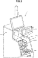
- Fig. 3 is a perspective view illustrating the appearance of the first housing 11 of which the door 111 is opened.
- the door 111 rotates in the vertical direction around a hinge section 111a.
- the first housing 11 houses a money depositing/dispensing section 4.
- the money depositing/dispensing section 4 is composed of a bill change machine (bill depositing/dispensing device) 41 and a coil change machine (coin depositing/dispensing device) 42.
- the first housing 11 rotates the door 111 upwards to open the inside of the first housing 11 to expose the bill change machine 41 and the coil change machine 42.
- the second housing 12 houses the control section 7.
- the reading section 5 is equipped with a scanner 50 for reading the appearance of a commodity and a symbol (barcode and the like) attached to the commodity to specify the commodity. Further, the reading section 5 is equipped with a printer 51 for printing a receipt according to a commodity sales data processing executed by the control section 7.
- the printer 51 includes a receipt discharge table 51a, which supports a discharged receipt, protruding from the first housing 11.
- the receipt discharge table 51a is a convex-shaped table protruding from the first housing 11.
- the reading section 5 is equipped with a card reader 52 for carrying out reading of a credit card in a settlement processing executed by the control section 7.
- the display and operation section 6 is provided with a monitor 61 and a touch panel 62.
- the monitor 61 displays an image according to control of the control section 7.
- the touch panel 62 is arranged on the surface of the monitor 61 to output information relating to a position on the panel 62 touched by an operator to the control section 7.
- the basket placing shelf 2 is an article placing table on which a basket is placed at the time a commodity in the basket is taken out and held over the reading section 5.
- the basket placing shelf 2 is arranged at one of the sides of the settlement terminal 1.
- the bagging shelf 3 is a table for bagging the scanned commodity.
- the bagging shelf 3 is arranged at the other side of the settlement terminal 1 (at the opposite side of the basket placing shelf 2).
- Fig. 4 is a front view illustrating the appearance of the money depositing/dispensing section 4 of the settlement terminal 1 in a state in which the door 111 is removed.
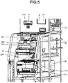
- Fig. 5 is a perspective view similarly illustrating the appearance of the money depositing/dispensing section 4 of the settlement terminal 1 in a state in which the door 111 is removed.
- the bill change machine 41 and the coin change machine 42 are housed in the first housing 11 in a stacking manner in a state in which the bill change machine 41 is located below the coil change machine 42.
- the bill change machine 41 determines an authenticity (true or false) of acquired bills to store them (genuine bills) as specie and dispenses bills as change.
- the coil change machine 42 determines true or false of acquired coins to store them as specie and dispenses coins as change.
- the bill change machine 41 and the coil change machine 42 notify the control section 7 of the amount of the stored money. Further, the bill change machine 41 and the coil change machine 42 receive notification of amount to be dispensed as change from the control section 7.
- the control section 7 collectively controls each section (the money depositing/dispensing section 4, the reading section 5, and the display and operation section 6) included in the settlement terminal 1.
- the control section 7 acquires code information from the reading section 5.
- the control section 7 outputs information to be displayed on the monitor 61 of the display and operation section 6 and acquires information of operations carried out by an operator through the touch panel 62. Further, the control section 7 grasps money deposited to the money depositing/dispensing section 4 to instruct dispensing of money to the money depositing/dispensing section 4.
- a depositing port (coin depositing port or coin reception port) 421 for coins to be deposited to the coin change machine 42 is arranged at one of the end sides of the upper part of the first housing 11.
- a stage (surface) including a coin discharge dish (coin dispensing port) 422 and a reject dish 423 and a stage including a bill depositing port (bill reception port) 411 and a bill discharge port (bill dispensing port) 412 are arranged in a stepwise manner in order from the back side at which the coin depositing port 421 is arranged to the front side.
- the coin depositing port 421 is arranged at the upper stage
- the coin discharge dish 422 and the reject dish 423 are arranged at the middle stage
- the bill depositing port 411 and the bill discharge port 412 are arranged at the lower stage.
- the coin discharge dish 422 is a reception dish for receiving a coin discharged from the coil change machine 42.
- the reject dish 423 is a reception dish for receiving a coin (reject coin) such as a deformed coin, a foreign coin and a counterfeit coin which are not stored in the coil change machine 42.
- a positional relationship of the coin depositing port 421, the coin discharge dish 422 and the reject dish 423 depends on the structure of the coil change machine 42.
- the coin depositing port 421 and the coin discharge dish 422 are arranged at positions separated along the width direction of the first housing 11. In this manner, the coin depositing port 421 and the coin discharge dish 422 are arranged apart from each other in the height direction, the width direction and the depth direction, and thus visibility and operability for the coin discharge dish 422 are increased. Furthermore, the reject dish 423 is arranged at the lower position of the coin depositing port 421 in parallel with the coin discharge dish 422.
- the bill depositing port 411 receives bills to be deposited to the bill change machine 41.
- the bill discharge port 412 dispenses bills from the bill change machine 41.
- a position-relationship between the bill depositing port 411 and the bill discharge port 412 depends on the structure of the bill change machine 41. Further, the bill depositing port 411 and the bill discharge port 412 are separated (shifted) along the width direction of the first housing 11 with respect to the coin discharge dish 422.
- LEDs 43 ⁇ 46 for informing an operation procedure or an error state are arranged respectively in the vicinity of the coin depositing port 421, the coin discharge dish 422, the reject dish 423, the bill depositing port 411 and the bill discharge port 412. Positions at which the LEDs 43 ⁇ 46 are arranged are not limited in particular as long as they are located in the vicinity of each section. Further, the number and the arrangement of the LEDs 43 ⁇ 46 are not limited in particular.
- Fig. 6 is a perspective view illustrating the appearance of the collection bag 8.
- a symbol 421a in Fig. 6 denotes a destination (money depositing port of the coin change machine 42) to which a coin deposited from the coin depositing port 421 of the first housing 11 is guided.
- the collection bag 8 is a container for receiving coin to be collected from the coin change machine 42 or coin to be retracted or saved at the time of overflow.
- the collection of the coin is carried out, for example, at the time the business is closed.
- the overflow is a case in which a storage amount of the coin change machine 42 exceeds a predetermined reference value.
- the collection bag 8 is detachably mounted below the coin discharge dish 422.
- the coin change machine 42 includes a route for guiding a coin onto the coin discharge dish 422 and a route for guiding a coin to the collection bag 8 below the coin discharge dish 422, and switches a route for discharging a coin to either of the two routes according to a situation.
- the bill change machine 41 is arranged at a position shifted with respect to the coin change machine 42 in the width direction such that a space is left at a position, i.e., a lower part of the coin discharge dish 422, adjacent to the bill change machine 41.
- the collection bag 8 is formed in a shape suitable to this space.
- the collection bag 8 includes a bag part 81 and a frame 82.
- the frame 82 includes a frame section 821 and a holding section 822. Opening of the bag part 81 is attached to the frame section 821, and in this way, the frame section 821 supports the bag part 81.
- the holding section 822 is formed at the front side of the frame section 821, and is used as a handle at the time of detaching the collection bag 8. In Fig. 6 , in order to expose the frame section 821, the collection bag 8 slightly pulled out to the front side is illustrated.
- Fig. 7 is a front view illustrating a shape of the bag part in a state in which the bag part is simplified.
- the bag part 81 is formed in a different shape in a vertical direction but not a general shape with the same width from the upper part to the lower part such that the width of the upper part is different from that of the lower part.
- the bag part 81 has a shape which does not interfere with the bill depositing port 411 and the bill discharge port 412.
- the bag part 81 is described step by step in an upper bag part 811, a lower bag part 812 and an inclined surface 813, respectively.
- the lower bag part 812 constitutes a hanging section for filling in the space adjacent to the bill change machine 41.
- the upper bag part 811 and the inclined surface 813 constitute a guide section for guiding a coin from the coin discharge dish 422 to the hanging section (lower bag part 812).
- the upper bag part 811 is located at a space between the coin change machine 42 and the bill change machine 41, and has the same width and length as the coin discharge dish 422.
- the upper bag part 811 is located at the side but not on the bill depositing port 411 and the bill discharge port 412.
- the lower bag part 812 has a width fitted in the space left at the side of the bill change machine 41 in the first housing 11.
- the width of the lower bag part 812 is larger towards the lower end side. In other words, a size indicated by b is larger than that indicated by a in Fig. 7 .
- the lower bag part 812 is connected with one of the sides of the upper bag part 811.
- the inclined surface 813 descending towards the lower bag part 812 is arranged between the other side of the upper bag part 811 and the upper end of the lower bag part 812.
- the inclined surface 813 gradually narrows the width of the upper bag part 811, and further guides the coin entering the upper bag part 811 to the lower bag part 812.
- the coin change machine 42 including the collection bag 8 stated above discharges coin to the coin discharge dish 422 or the collection bag 8. Whether the guide destination of the coin is selected to the coin discharge dish 422 or the collection bag 8 depends on the storage amount (emptiness condition or availability) of the coin change machine 42. If the storage amount of the coin change machine 42 is a full state or a state close to the full state (for example, a state in which the storage amount is greater than the predetermined number of coins (threshold value)), the coin change machine 42 discharges coins to the collection bag 8.
- Fig. 8 is a block diagram illustrating the hardware constitution of the self-POS 100.
- the settlement terminal 1 is equipped with the control section 7, an I/O device control section 71 and a communication I/F (interface) 72.
- the communication I/F 72 connects the settlement terminal 1 with the bagging shelf 3 to perform communication.
- the I/O device control section 71 connects the control section 7 with the bill change machine 41, the coin change machine 42, the LEDs 43 ⁇ 46, the scanner 50, the printer 51, the card reader 52, the monitor 61 and the touch panel 62.
- the bagging shelf 3 is equipped with an I/O device control section 31, a communication I/F (Interface) 32 and a weighing device 33.
- the weighing device 33 measures the weight of an article placed on the bagging shelf 3.
- the communication I/F 32 connects the bagging shelf 3 with the settlement terminal 1 to perform communication.
- the I/O device control section 31 connects the weighing device 33 with the control section 7 via the communication I/F 32 and the communication I/F 72.
- the weighing device 33 measures the weight of the article placed on the bagging shelf 3 for the purpose of unfair conduct prevention.
- the control section 7 includes a CPU (Central Processing Unit), a ROM (Read Only Memory) and a RAM (Random Access Memory).
- the ROM stores various computer programs executed by the CPU and various data.
- the RAM temporarily stores data and a computer program at the time the CPU executes the computer program.
- the control section 7 collectively controls each section in such a manner that the CPU copies or decompresses a computer program read from the ROM on the RAM to execute the computer program.
- the self-POS 100 is used in a state of attaching the collection bag 8 to the coin change machine 42.
- the control section 7 controls the coin change machine 42 to save coin to the collection bag 8 if the coin change machine 42 becomes an overflow state.
- the coin change machine 42 discharges coin to the collection bag 8
- the coin enters the bag part 81 of the collection bag 8. Since the upper bag part 811 has a wide opening, a coin discharge path for coin collection is wide and thus, the coin collection can be carried out quickly. Further, since the lower bag part 812 has a narrow and elongated path and the bag part 81 is formed in a constricted shape, and thus the coins collected in the lower bag part 812 are effectively trapped. Furthermore, since the lower bag part 812 has a wide lower end (bottom), the stored coins become stable.
- the collection bag 8 has a capacity capable of collecting all the coins stored by the coin change machine 42. In a case of saving coins to the collection bag 8 at the time of overflow, coins for change are left in the coin change machine 42, and thus the amount of coins transferred to the collection bag 8 is smaller than that collected at the time of the coin collection. Thus, according to the present embodiment, a person who attends to the overflow is not required.
Landscapes
- Physics & Mathematics (AREA)
- General Physics & Mathematics (AREA)
- Cash Registers Or Receiving Machines (AREA)
Abstract
Description
- The present invention relates to registration processing technologies in general and, in particular, embodiments described herein relate to a money depositing/dispensing apparatus, as well as the corresponding system and method.
- In recent years, a money depositing/dispensing apparatus such as a self-checkout register (referred to as a self-checkout apparatus or a self-checkout POS (Point Of Sales) terminal) is used. The self-checkout register is installed in a retail store such as a supermarket to carry out a registration processing and a settlement processing of purchased commodities by a customer himself/herself. The self-checkout register is equipped with a coin depositing/dispensing device and a bill depositing/dispensing device.
- The coin depositing/dispensing device receives coins for payment to store the coins in a storage section, and dispenses coins as change from the storage section. If coins overflow, in other words, if the amount of the coins available for being stored in the storage section reaches an upper limit, the conventional self-checkout register becomes a state in which the settlement processing cannot be carried out, and a work for dealing with such problem by a store clerk is required. The store clerk firstly opens a door of the self-checkout register, to attach a dedicated container such as a bag to the coin depositing/dispensing device, and collects coins stored in the storage section into the container. A customer cannot use the self-checkout register while the dealing work is carried out.
- An unusable state caused by the overflow of coins as stated above can occur in any device for depositing/dispensing coins not limited to the self-checkout register.
- To solve such problems, there is provided a money depositing/dispensing apparatus, comprising:
- a coin depositing/dispensing device, configured to store coin acquired through a coin reception port, which includes a first path for discharging the stored coin to a coin dispensing port and a second path for saving the stored coin;
- a bill depositing/dispensing device, configured to store bill acquired through a bill reception port and discharge the stored bill to a bill dispensing port, which is arranged at the lower side of the coin depositing/dispensing device where a space is formed at the lower part of the coin dispensing port; and
- a container, configured to store coin passing through the second path, which is detachably attached in the coin depositing/dispensing device to fill the space.
- Preferably, the container includes a hanging section which fills the space, and a guide section located at the upper part of the hanging section to guide coin passing through the second path to the hanging section.
- Preferably still, the guide section includes an inclined surface descending towards the hanging section.
- Preferably yet, the hanging section includes a lower end the width of which is larger than that of parts other than the lower end.
- Suitably, the money depositing/dispensing apparatus further comprises:
- a control module configured to save coin to the container in a case in which the number of coins stored in the coin depositing/dispensing device becomes a predetermined number thereof, wherein
- the money depositing/dispensing device is used in a state in which the container is attached thereto.
- The invention also relates to a money depositing/dispensing system, comprising:
- a coin depositing/dispensing means, configured to store coin acquired through a coin reception port, which includes a first path for discharging the stored coin to a coin dispensing port and a second path for saving the stored coin;
- a bill depositing/dispensing means, configured to store bill acquired through a bill reception port and discharge the stored bill to a bill dispensing port, which is arranged at the lower side of the coin depositing/dispensing means where a space is formed at the lower part of the coin dispensing port; and
- a container means, configured to store coin passing through the second path, which is detachably attached in the coin depositing/dispensing means to fill the space.
- Preferably, the container means includes a hanging section which fills the space, and a guide section located at the upper part of the hanging section to guide coin passing through the second path to the hanging section.
- Preferably still, the guide section includes an inclined surface descending towards the hanging section.
- Suitably, the hanging section includes a lower end the width of which is larger than that of parts other than the lower end.
- Suitably yet, the money depositing/dispensing system further comprises:
- a control module means configured to save coin to the container in a case in which the number of coins stored in the coin depositing/dispensing means becomes a predetermined number thereof, wherein
- the money depositing/dispensing means is used in a state in which the container is attached thereto.
- The invention further concerns a method for depositing/dispensing money, comprising the steps of:
- storing, by a coin depositing/dispensing device, coin acquired through a coin reception port, which includes a first path for discharging the stored coin to a coin dispensing port and a second path for saving the stored coin;
- storing, by a bill depositing/dispensing device, bill acquired through a bill reception port and discharge the stored bill to a bill dispensing port, which is arranged at the lower side of the coin depositing/dispensing device where a space is formed at the lower part of the coin dispensing port; and
- storing, by a container, coin passing through the second path, which is detachably attached in the coin depositing/dispensing device to fill the space.
- Preferably, the container includes a hanging section which fills the space, and a guide section located at the upper part of the hanging section to guide coin passing through the second path to the hanging section.
- Preferably still, the guide section includes an inclined surface descending towards the hanging section.
- Preferably yet, the hanging section includes a lower end the width of which is larger than that of parts other than the lower end.
- Typically, the method further comprises the step of:
- saving, by a control module , coin to the container in a case in which the number of coins stored in the coin depositing/dispensing device becomes a predetermined number thereof, wherein
- The above and other objects, features and advantages of the present invention will be made apparent from the following description of the preferred embodiments, given as non-limiting examples, with reference to the accompanying drawings, in which:
-
Fig. 1 is a front view illustrating the appearance of a self-checkout register according to an embodiment; -
Fig. 2 is a perspective view illustrating the appearance of the self-checkout register when viewed from oblique upside; -
Fig. 3 is a perspective view illustrating the appearance of a first housing of which a door is opened; -
Fig. 4 is a front view illustrating the appearance of a money depositing/dispensing section of a settlement terminal in a state in which a door is removed; -
Fig. 5 is a perspective view illustrating the appearance of the money depositing/dispensing section of the settlement terminal in a state in which a door is removed; -
Fig. 6 is a perspective view illustrating the appearance of a collection bag; -
Fig. 7 is a front view illustrating a shape of the bag part in a state in which the bag part is simplified; and -
Fig. 8 is a block diagram illustrating the hardware constitution of the self-checkout register. - In accordance with an embodiment, a money depositing/dispensing apparatus comprises a coin depositing/dispensing device configured to store coin acquired through a coin reception port and to discharge the stored coin through a coin dispensing port; a bill depositing/dispensing device, configured to store bill acquired through a bill reception port and discharge the stored bill to a bill dispensing port, which is arranged at the lower side of the coin depositing/dispensing device where a space is formed at the upper part of the coin dispensing port; and a container, configured to collect coin discharged by the coin depositing/dispensing device, which is detachably attached in the coin depositing/dispensing device to fill the space.
- Hereinafter, an embodiment of a money depositing/dispensing apparatus is described in detail with reference to the accompanying drawings. In the present embodiment, a self-checkout register (referred to as a self-checkout POS (Point Of Sales) terminal) is described as an example of the money depositing/dispensing apparatus. The self-checkout register is a terminal device for carrying out a commodity registration processing and a settlement processing of purchased commodities by a customer.
- In the same manner, a money depositing/dispensing system can be implemented as above, as well as a method for depositing/dispensing money.
-
Fig. 1 is a front view illustrating the appearance of a self-checkout register 100 according to an embodiment.Fig. 2 is a perspective view illustrating the appearance of the self-checkout register 100 when viewed from oblique upside. The self-checkout register 100 (hereinafter referred to as a self-POS) is provided with asettlement terminal 1, a basket placingshelf 2 and abagging shelf 3. Thesettlement terminal 1 is equipped with a money depositing/dispensingsection 4, areading section 5, a display andoperation section 6, and a control section 7 (refer toFig. 8 ) for controlling each section. - The
settlement terminal 1 is provided with afirst housing 11 and asecond housing 12. Thefirst housing 11 is provided with an openable andclosable door 111.Fig. 3 is a perspective view illustrating the appearance of thefirst housing 11 of which thedoor 111 is opened. Thedoor 111 rotates in the vertical direction around ahinge section 111a. Thefirst housing 11 houses a money depositing/dispensing section 4. The money depositing/dispensing section 4 is composed of a bill change machine (bill depositing/dispensing device) 41 and a coil change machine (coin depositing/dispensing device) 42. Thefirst housing 11 rotates thedoor 111 upwards to open the inside of thefirst housing 11 to expose thebill change machine 41 and thecoil change machine 42. Returning toFig. 1 andFig. 2 , thesecond housing 12 houses thecontrol section 7. - The
reading section 5 is equipped with ascanner 50 for reading the appearance of a commodity and a symbol (barcode and the like) attached to the commodity to specify the commodity. Further, thereading section 5 is equipped with aprinter 51 for printing a receipt according to a commodity sales data processing executed by thecontrol section 7. Theprinter 51 includes a receipt discharge table 51a, which supports a discharged receipt, protruding from thefirst housing 11. The receipt discharge table 51a is a convex-shaped table protruding from thefirst housing 11. Thereading section 5 is equipped with acard reader 52 for carrying out reading of a credit card in a settlement processing executed by thecontrol section 7. - The display and
operation section 6 is provided with amonitor 61 and atouch panel 62. Themonitor 61 displays an image according to control of thecontrol section 7. Thetouch panel 62 is arranged on the surface of themonitor 61 to output information relating to a position on thepanel 62 touched by an operator to thecontrol section 7. - The
basket placing shelf 2 is an article placing table on which a basket is placed at the time a commodity in the basket is taken out and held over thereading section 5. Thebasket placing shelf 2 is arranged at one of the sides of thesettlement terminal 1. - The
bagging shelf 3 is a table for bagging the scanned commodity. Thebagging shelf 3 is arranged at the other side of the settlement terminal 1 (at the opposite side of the basket placing shelf 2). -
Fig. 4 is a front view illustrating the appearance of the money depositing/dispensing section 4 of thesettlement terminal 1 in a state in which thedoor 111 is removed.Fig. 5 is a perspective view similarly illustrating the appearance of the money depositing/dispensing section 4 of thesettlement terminal 1 in a state in which thedoor 111 is removed. Thebill change machine 41 and thecoin change machine 42 are housed in thefirst housing 11 in a stacking manner in a state in which thebill change machine 41 is located below thecoil change machine 42. - The
bill change machine 41 determines an authenticity (true or false) of acquired bills to store them (genuine bills) as specie and dispenses bills as change. Thecoil change machine 42 determines true or false of acquired coins to store them as specie and dispenses coins as change. Thebill change machine 41 and thecoil change machine 42 notify thecontrol section 7 of the amount of the stored money. Further, thebill change machine 41 and thecoil change machine 42 receive notification of amount to be dispensed as change from thecontrol section 7. - The
control section 7 collectively controls each section (the money depositing/dispensing section 4, thereading section 5, and the display and operation section 6) included in thesettlement terminal 1. Thecontrol section 7 acquires code information from thereading section 5. Thecontrol section 7 outputs information to be displayed on themonitor 61 of the display andoperation section 6 and acquires information of operations carried out by an operator through thetouch panel 62. Further, thecontrol section 7 grasps money deposited to the money depositing/dispensing section 4 to instruct dispensing of money to the money depositing/dispensing section 4. - As shown in
Fig. 2 , a depositing port (coin depositing port or coin reception port) 421 for coins to be deposited to thecoin change machine 42 is arranged at one of the end sides of the upper part of thefirst housing 11. In the first housing 11 (money depositing/dispensing section 4), a stage (surface) including a coin discharge dish (coin dispensing port) 422 and areject dish 423 and a stage including a bill depositing port (bill reception port) 411 and a bill discharge port (bill dispensing port) 412 are arranged in a stepwise manner in order from the back side at which thecoin depositing port 421 is arranged to the front side. In other words, thecoin depositing port 421 is arranged at the upper stage, thecoin discharge dish 422 and thereject dish 423 are arranged at the middle stage, and thebill depositing port 411 and thebill discharge port 412 are arranged at the lower stage. In this manner, by arranging various kinds of depositing ports and discharge ports (discharge dishes) in a stepwise manner, all the depositing ports and the discharge ports (discharge dishes) can be seen from the back side to the front side. - The
coin discharge dish 422 is a reception dish for receiving a coin discharged from thecoil change machine 42. Thereject dish 423 is a reception dish for receiving a coin (reject coin) such as a deformed coin, a foreign coin and a counterfeit coin which are not stored in thecoil change machine 42. A positional relationship of thecoin depositing port 421, thecoin discharge dish 422 and thereject dish 423 depends on the structure of thecoil change machine 42. - The
coin depositing port 421 and thecoin discharge dish 422 are arranged at positions separated along the width direction of thefirst housing 11. In this manner, thecoin depositing port 421 and thecoin discharge dish 422 are arranged apart from each other in the height direction, the width direction and the depth direction, and thus visibility and operability for thecoin discharge dish 422 are increased. Furthermore, thereject dish 423 is arranged at the lower position of thecoin depositing port 421 in parallel with thecoin discharge dish 422. - The
bill depositing port 411 receives bills to be deposited to thebill change machine 41. Thebill discharge port 412 dispenses bills from thebill change machine 41. A position-relationship between thebill depositing port 411 and thebill discharge port 412 depends on the structure of thebill change machine 41. Further, thebill depositing port 411 and thebill discharge port 412 are separated (shifted) along the width direction of thefirst housing 11 with respect to thecoin discharge dish 422. - In addition, LEDs (Light Emitting Diode) 43∼46 for informing an operation procedure or an error state are arranged respectively in the vicinity of the
coin depositing port 421, thecoin discharge dish 422, thereject dish 423, thebill depositing port 411 and thebill discharge port 412. Positions at which theLEDs 43∼46 are arranged are not limited in particular as long as they are located in the vicinity of each section. Further, the number and the arrangement of theLEDs 43∼46 are not limited in particular. - As shown in
Fig. 4 andFig. 5 , the self-POS 100 is provided with acollection bag 8.Fig. 6 is a perspective view illustrating the appearance of thecollection bag 8. Asymbol 421a inFig. 6 denotes a destination (money depositing port of the coin change machine 42) to which a coin deposited from thecoin depositing port 421 of thefirst housing 11 is guided. - The
collection bag 8 is a container for receiving coin to be collected from thecoin change machine 42 or coin to be retracted or saved at the time of overflow. The collection of the coin is carried out, for example, at the time the business is closed. The overflow is a case in which a storage amount of thecoin change machine 42 exceeds a predetermined reference value. - The
collection bag 8 is detachably mounted below thecoin discharge dish 422. Thecoin change machine 42 includes a route for guiding a coin onto thecoin discharge dish 422 and a route for guiding a coin to thecollection bag 8 below thecoin discharge dish 422, and switches a route for discharging a coin to either of the two routes according to a situation. - The
bill change machine 41 is arranged at a position shifted with respect to thecoin change machine 42 in the width direction such that a space is left at a position, i.e., a lower part of thecoin discharge dish 422, adjacent to thebill change machine 41. Thecollection bag 8 is formed in a shape suitable to this space. - The
collection bag 8 includes abag part 81 and aframe 82. Theframe 82 includes aframe section 821 and aholding section 822. Opening of thebag part 81 is attached to theframe section 821, and in this way, theframe section 821 supports thebag part 81. The holdingsection 822 is formed at the front side of theframe section 821, and is used as a handle at the time of detaching thecollection bag 8. InFig. 6 , in order to expose theframe section 821, thecollection bag 8 slightly pulled out to the front side is illustrated. -
Fig. 7 is a front view illustrating a shape of the bag part in a state in which the bag part is simplified. Thebag part 81 is formed in a different shape in a vertical direction but not a general shape with the same width from the upper part to the lower part such that the width of the upper part is different from that of the lower part. Thebag part 81 has a shape which does not interfere with thebill depositing port 411 and thebill discharge port 412. - The
bag part 81 is described step by step in anupper bag part 811, alower bag part 812 and aninclined surface 813, respectively. Thelower bag part 812 constitutes a hanging section for filling in the space adjacent to thebill change machine 41. Theupper bag part 811 and theinclined surface 813 constitute a guide section for guiding a coin from thecoin discharge dish 422 to the hanging section (lower bag part 812). - The
upper bag part 811 is located at a space between thecoin change machine 42 and thebill change machine 41, and has the same width and length as thecoin discharge dish 422. Theupper bag part 811 is located at the side but not on thebill depositing port 411 and thebill discharge port 412. Thelower bag part 812 has a width fitted in the space left at the side of thebill change machine 41 in thefirst housing 11. The width of thelower bag part 812 is larger towards the lower end side. In other words, a size indicated by b is larger than that indicated by a inFig. 7 . - The
lower bag part 812 is connected with one of the sides of theupper bag part 811. Theinclined surface 813 descending towards thelower bag part 812 is arranged between the other side of theupper bag part 811 and the upper end of thelower bag part 812. Theinclined surface 813 gradually narrows the width of theupper bag part 811, and further guides the coin entering theupper bag part 811 to thelower bag part 812. - The
coin change machine 42 including thecollection bag 8 stated above discharges coin to thecoin discharge dish 422 or thecollection bag 8. Whether the guide destination of the coin is selected to thecoin discharge dish 422 or thecollection bag 8 depends on the storage amount (emptiness condition or availability) of thecoin change machine 42. If the storage amount of thecoin change machine 42 is a full state or a state close to the full state (for example, a state in which the storage amount is greater than the predetermined number of coins (threshold value)), thecoin change machine 42 discharges coins to thecollection bag 8. - Next, the hardware constitution of the self-
POS 100 is described.Fig. 8 is a block diagram illustrating the hardware constitution of the self-POS 100. Thesettlement terminal 1 is equipped with thecontrol section 7, an I/Odevice control section 71 and a communication I/F (interface) 72. - The communication I/
F 72 connects thesettlement terminal 1 with thebagging shelf 3 to perform communication. The I/Odevice control section 71 connects thecontrol section 7 with thebill change machine 41, thecoin change machine 42, theLEDs 43∼46, thescanner 50, theprinter 51, thecard reader 52, themonitor 61 and thetouch panel 62. - On the other hand, the
bagging shelf 3 is equipped with an I/Odevice control section 31, a communication I/F (Interface) 32 and a weighingdevice 33. The weighingdevice 33 measures the weight of an article placed on thebagging shelf 3. The communication I/F 32 connects thebagging shelf 3 with thesettlement terminal 1 to perform communication. The I/Odevice control section 31 connects the weighingdevice 33 with thecontrol section 7 via the communication I/F 32 and the communication I/F 72. The weighingdevice 33 measures the weight of the article placed on thebagging shelf 3 for the purpose of unfair conduct prevention. - The
control section 7 includes a CPU (Central Processing Unit), a ROM (Read Only Memory) and a RAM (Random Access Memory). The ROM stores various computer programs executed by the CPU and various data. The RAM temporarily stores data and a computer program at the time the CPU executes the computer program. Thecontrol section 7 collectively controls each section in such a manner that the CPU copies or decompresses a computer program read from the ROM on the RAM to execute the computer program. - In such a constitution, the self-
POS 100 is used in a state of attaching thecollection bag 8 to thecoin change machine 42. Thecontrol section 7 controls thecoin change machine 42 to save coin to thecollection bag 8 if thecoin change machine 42 becomes an overflow state. - In a case in which the
coin change machine 42 discharges coin to thecollection bag 8, the coin enters thebag part 81 of thecollection bag 8. Since theupper bag part 811 has a wide opening, a coin discharge path for coin collection is wide and thus, the coin collection can be carried out quickly. Further, since thelower bag part 812 has a narrow and elongated path and thebag part 81 is formed in a constricted shape, and thus the coins collected in thelower bag part 812 are effectively trapped. Furthermore, since thelower bag part 812 has a wide lower end (bottom), the stored coins become stable. - The
collection bag 8 has a capacity capable of collecting all the coins stored by thecoin change machine 42. In a case of saving coins to thecollection bag 8 at the time of overflow, coins for change are left in thecoin change machine 42, and thus the amount of coins transferred to thecollection bag 8 is smaller than that collected at the time of the coin collection. Thus, according to the present embodiment, a person who attends to the overflow is not required. - While certain embodiments have been described, these embodiments have been presented by way of example only, and are not intended to limit the scope of the invention. Indeed, the novel embodiments described herein may be embodied in a variety of other forms; furthermore, various omissions, substitutions and changes in the form of the embodiments described herein may be made without departing from the framework of the invention. The accompanying claims and their equivalents are intended to cover such forms or modifications as would fall within the scope and framework of the invention.
Claims (15)
- A money depositing/dispensing apparatus, comprising:a coin depositing/dispensing device, configured to store coin acquired through a coin reception port, which includes a first path for discharging the stored coin to a coin dispensing port and a second path for saving the stored coin;a bill depositing/dispensing device, configured to store bill acquired through a bill reception port and discharge the stored bill to a bill dispensing port, which is arranged at the lower side of the coin depositing/dispensing device where a space is formed at the lower part of the coin dispensing port; anda container, configured to store coin passing through the second path, which is detachably attached in the coin depositing/dispensing device to fill the space.
- The money depositing/dispensing apparatus according to claim 1, wherein
the container includes a hanging section which fills the space, and a guide section located at the upper part of the hanging section to guide coin passing through the second path to the hanging section. - The money depositing/dispensing apparatus according to claim 2, wherein
the guide section includes an inclined surface descending towards the hanging section. - The money depositing/dispensing apparatus according to claim 2 or 3, wherein
the hanging section includes a lower end the width of which is larger than that of parts other than the lower end. - The money depositing/dispensing apparatus according to any one of claims 1 to 4, further comprising:a control module configured to save coin to the container in a case in which the number of coins stored in the coin depositing/dispensing device becomes a predetermined number thereof, whereinthe money depositing/dispensing device is used in a state in which the container is attached thereto.
- A money depositing/dispensing system, comprising:a coin depositing/dispensing means, configured to store coin acquired through a coin reception port, which includes a first path for discharging the stored coin to a coin dispensing port and a second path for saving the stored coin;a bill depositing/dispensing means, configured to store bill acquired through a bill reception port and discharge the stored bill to a bill dispensing port, which is arranged at the lower side of the coin depositing/dispensing means where a space is formed at the lower part of the coin dispensing port; anda container means, configured to store coin passing through the second path, which is detachably attached in the coin depositing/dispensing means to fill the space.
- The money depositing/dispensing system according to claim 6, wherein the container means includes a hanging section which fills the space, and a guide section located at the upper part of the hanging section to guide coin passing through the second path to the hanging section.
- The money depositing/dispensing system according to claim 7, wherein the guide section includes an inclined surface descending towards the hanging section.
- The money depositing/dispensing system according to claim 7 or 8, wherein
the hanging section includes a lower end the width of which is larger than that of parts other than the lower end. - The money depositing/dispensing system according to any one of claims 6 to 9, further comprising:a control module means configured to save coin to the container in a case in which the number of coins stored in the coin depositing/dispensing means becomes a predetermined number thereof, whereinthe money depositing/dispensing means is used in a state in which the container is attached thereto.
- A method for depositing/dispensing money, comprising the steps of:- storing, by a coin depositing/dispensing device, coin acquired through a coin reception port, which includes a first path for discharging the stored coin to a coin dispensing port and a second path for saving the stored coin;- storing, by a bill depositing/dispensing device, bill acquired through a bill reception port and discharge the stored bill to a bill dispensing port, which is arranged at the lower side of the coin depositing/dispensing device where a space is formed at the lower part of the coin dispensing port; and- storing, by a container, coin passing through the second path, which is detachably attached in the coin depositing/dispensing device to fill the space.
- The method according to claim 11, wherein
the container includes a hanging section which fills the space, and a guide section located at the upper part of the hanging section to guide coin passing through the second path to the hanging section. - The method according to claim 12, wherein
the guide section includes an inclined surface descending towards the hanging section. - The method according to claim 12 or 13, wherein
the hanging section includes a lower end the width of which is larger than that of parts other than the lower end. - The method according to any one of claims 11 to 14, further comprising the step of:- saving, by a control module , coin to the container in a case in which the number of coins stored in the coin depositing/dispensing device becomes a predetermined number thereof, whereinthe money depositing/dispensing device is used in a state in which the container is attached thereto.
Applications Claiming Priority (1)
| Application Number | Priority Date | Filing Date | Title |
|---|---|---|---|
| JP2016020732A JP6088677B1 (en) | 2016-02-05 | 2016-02-05 | Payment device |
Publications (1)
| Publication Number | Publication Date |
|---|---|
| EP3203451A1 true EP3203451A1 (en) | 2017-08-09 |
Family
ID=57963091
Family Applications (1)
| Application Number | Title | Priority Date | Filing Date |
|---|---|---|---|
| EP17154509.8A Withdrawn EP3203451A1 (en) | 2016-02-05 | 2017-02-03 | Money depositing/dispensing apparatus |
Country Status (4)
| Country | Link |
|---|---|
| US (1) | US20170224134A1 (en) |
| EP (1) | EP3203451A1 (en) |
| JP (1) | JP6088677B1 (en) |
| CN (1) | CN107045748A (en) |
Cited By (1)
| Publication number | Priority date | Publication date | Assignee | Title |
|---|---|---|---|---|
| CN118414643A (en) * | 2022-02-03 | 2024-07-30 | 东芝泰格有限公司 | Checkout Device |
Families Citing this family (5)
| Publication number | Priority date | Publication date | Assignee | Title |
|---|---|---|---|---|
| JP7036580B2 (en) * | 2017-12-13 | 2022-03-15 | グローリー株式会社 | Money deposit machine and accounting system |
| ZA201904689B (en) | 2018-07-30 | 2020-05-27 | Cima | Machine for depositing and dispensing coins |
| IT201800007620A1 (en) * | 2018-07-30 | 2020-01-30 | Cima | Coin depositing and dispensing machine. |
| JP7711913B2 (en) * | 2021-01-12 | 2025-07-23 | 日本電気株式会社 | Information processing device |
| JP7687977B2 (en) * | 2022-02-03 | 2025-06-03 | 東芝テック株式会社 | Collection bag support structure |
Citations (5)
| Publication number | Priority date | Publication date | Assignee | Title |
|---|---|---|---|---|
| US3677461A (en) * | 1970-07-23 | 1972-07-18 | Reynolds Products | Security device |
| US20020130011A1 (en) * | 2001-03-19 | 2002-09-19 | Casanova Scott D. | Coin processing machine having coin-impact surfaces made from laminated metal |
| US20090101723A1 (en) * | 2007-10-22 | 2009-04-23 | Glory Ltd. | Bill/coin processing system |
| EP2410497A1 (en) * | 2009-03-19 | 2012-01-25 | Glory Ltd. | Currency handling machine |
| JP2014052714A (en) * | 2012-09-05 | 2014-03-20 | Toshiba Tec Corp | Currency dispensing device, bill dispensing device, and coin recovery method |
Family Cites Families (25)
| Publication number | Priority date | Publication date | Assignee | Title |
|---|---|---|---|---|
| JPH06119521A (en) * | 1991-10-14 | 1994-04-28 | Kazumi Chiba | Coin payout device |
| JPH07129804A (en) * | 1993-11-08 | 1995-05-19 | Eagle:Kk | Money changer |
| JPH07272054A (en) * | 1994-04-01 | 1995-10-20 | Toshiba Corp | Coin storage device |
| JPH103566A (en) * | 1996-06-14 | 1998-01-06 | Tec Corp | Coin deposit and withdrawal device |
| CN1180381C (en) * | 2001-07-26 | 2004-12-15 | 有限会社水贝总业 | Counting selector for coin |
| US6702093B2 (en) * | 2001-11-09 | 2004-03-09 | Park Place Entertainment Corp. | Gaming device stand |
| JP4536336B2 (en) * | 2003-06-10 | 2010-09-01 | グローリー株式会社 | Money handling system |
| CN2750988Y (en) * | 2004-11-15 | 2006-01-11 | 唐爱丽 | Rapid counting, collecting and wrapping device for coin |
| JP4665088B2 (en) * | 2005-01-28 | 2011-04-06 | 旭精工株式会社 | Coin hopper |
| CN101147176B (en) * | 2005-03-29 | 2010-10-13 | 光荣工业株式会社 | Banknote processing device |
| JP4744950B2 (en) * | 2005-06-27 | 2011-08-10 | グローリー株式会社 | Counterfeit money identification support device |
| US7946406B2 (en) * | 2005-11-12 | 2011-05-24 | Cummins-Allison Corp. | Coin processing device having a moveable coin receptacle station |
| JP4795056B2 (en) * | 2006-03-03 | 2011-10-19 | グローリー株式会社 | Change replenishment management system |
| US7681707B2 (en) * | 2006-04-14 | 2010-03-23 | Tabachnik Bruce M | Drawerless point of sale system and associated methods |
| JP4382845B2 (en) * | 2007-11-06 | 2009-12-16 | 東芝テック株式会社 | Self-checkout terminal |
| JP5193608B2 (en) * | 2008-01-15 | 2013-05-08 | ローレル精機株式会社 | Coin handling machine |
| JP5322770B2 (en) * | 2009-05-15 | 2013-10-23 | 沖電気工業株式会社 | Banknote handling equipment |
| JP5661331B2 (en) * | 2009-05-18 | 2015-01-28 | 株式会社ジェイ・エム・エス | Soft medical container and nutrient supply system using the same |
| JP2011054121A (en) * | 2009-09-04 | 2011-03-17 | Toshiba Tec Corp | Money receiving and dispensing unit |
| JP5373007B2 (en) * | 2011-08-02 | 2013-12-18 | 東芝テック株式会社 | Coin deposit / withdrawal device |
| EP2690605B1 (en) * | 2012-07-24 | 2015-04-29 | Scan Coin Ab | Dispensers for coin handling apparatus |
| US9378604B1 (en) * | 2013-06-27 | 2016-06-28 | Tim E. Rathjen | Coin recognition system and method |
| EP2908294B1 (en) * | 2014-02-14 | 2021-12-15 | Wincor Nixdorf International GmbH | Coin-sorting device with overflow catchment device |
| US10380820B2 (en) * | 2014-12-29 | 2019-08-13 | Tidel Engineering L.P. | Increased capacity coin hopper |
| US9741195B2 (en) * | 2015-04-13 | 2017-08-22 | Tidel Engineering, L.P. | Systems and methods for facilitating coin hopper maintenance |
-
2016
- 2016-02-05 JP JP2016020732A patent/JP6088677B1/en active Active
-
2017
- 2017-01-18 CN CN201710035457.XA patent/CN107045748A/en not_active Withdrawn
- 2017-02-01 US US15/421,639 patent/US20170224134A1/en not_active Abandoned
- 2017-02-03 EP EP17154509.8A patent/EP3203451A1/en not_active Withdrawn
Patent Citations (5)
| Publication number | Priority date | Publication date | Assignee | Title |
|---|---|---|---|---|
| US3677461A (en) * | 1970-07-23 | 1972-07-18 | Reynolds Products | Security device |
| US20020130011A1 (en) * | 2001-03-19 | 2002-09-19 | Casanova Scott D. | Coin processing machine having coin-impact surfaces made from laminated metal |
| US20090101723A1 (en) * | 2007-10-22 | 2009-04-23 | Glory Ltd. | Bill/coin processing system |
| EP2410497A1 (en) * | 2009-03-19 | 2012-01-25 | Glory Ltd. | Currency handling machine |
| JP2014052714A (en) * | 2012-09-05 | 2014-03-20 | Toshiba Tec Corp | Currency dispensing device, bill dispensing device, and coin recovery method |
Cited By (3)
| Publication number | Priority date | Publication date | Assignee | Title |
|---|---|---|---|---|
| CN118414643A (en) * | 2022-02-03 | 2024-07-30 | 东芝泰格有限公司 | Checkout Device |
| EP4475101A4 (en) * | 2022-02-03 | 2025-06-18 | Toshiba TEC Kabushiki Kaisha | CASH REGISTER DEVICE |
| US12525099B2 (en) | 2022-02-03 | 2026-01-13 | Toshiba Tec Kabushiki Kaisha | Check-out apparatus |
Also Published As
| Publication number | Publication date |
|---|---|
| JP2017138884A (en) | 2017-08-10 |
| JP6088677B1 (en) | 2017-03-01 |
| CN107045748A (en) | 2017-08-15 |
| US20170224134A1 (en) | 2017-08-10 |
Similar Documents
| Publication | Publication Date | Title |
|---|---|---|
| US20170224134A1 (en) | Money depositing/dispensing apparatus | |
| US10672235B2 (en) | Settlement apparatus | |
| US20240249580A1 (en) | Change machine | |
| JP6409144B2 (en) | Payment device | |
| JP7403795B2 (en) | Bag support device and product sales data processing device | |
| JP6637454B2 (en) | Self checkout device | |
| US9792496B2 (en) | Cash processing apparatus | |
| JP2013030029A (en) | Pos system and coin dispenser | |
| JP6134426B1 (en) | Payment device | |
| JP2022147121A (en) | Coin payment device | |
| JP4918073B2 (en) | Self-checkout terminal | |
| JP2020095755A (en) | Settlement device | |
| JP6522197B2 (en) | Payment device | |
| JP6666398B2 (en) | Payment device | |
| JP6680927B2 (en) | Payment device | |
| JP7698112B2 (en) | Accounting Equipment | |
| JP2023011817A (en) | money handling device | |
| JP2017182834A (en) | Settlement device | |
| JP2017097832A (en) | Settlement device | |
| JP2013235611A (en) | Pos system |
Legal Events
| Date | Code | Title | Description |
|---|---|---|---|
| PUAI | Public reference made under article 153(3) epc to a published international application that has entered the european phase |
Free format text: ORIGINAL CODE: 0009012 |
|
| STAA | Information on the status of an ep patent application or granted ep patent |
Free format text: STATUS: THE APPLICATION HAS BEEN PUBLISHED |
|
| AK | Designated contracting states |
Kind code of ref document: A1 Designated state(s): AL AT BE BG CH CY CZ DE DK EE ES FI FR GB GR HR HU IE IS IT LI LT LU LV MC MK MT NL NO PL PT RO RS SE SI SK SM TR |
|
| AX | Request for extension of the european patent |
Extension state: BA ME |
|
| STAA | Information on the status of an ep patent application or granted ep patent |
Free format text: STATUS: REQUEST FOR EXAMINATION WAS MADE |
|
| 17P | Request for examination filed |
Effective date: 20180209 |
|
| RBV | Designated contracting states (corrected) |
Designated state(s): AL AT BE BG CH CY CZ DE DK EE ES FI FR GB GR HR HU IE IS IT LI LT LU LV MC MK MT NL NO PL PT RO RS SE SI SK SM TR |
|
| STAA | Information on the status of an ep patent application or granted ep patent |
Free format text: STATUS: EXAMINATION IS IN PROGRESS |
|
| 17Q | First examination report despatched |
Effective date: 20201119 |
|
| STAA | Information on the status of an ep patent application or granted ep patent |
Free format text: STATUS: THE APPLICATION IS DEEMED TO BE WITHDRAWN |
|
| 18D | Application deemed to be withdrawn |
Effective date: 20230705 |