EP3203340A1 - Delivery vehicle - Google Patents
Delivery vehicle Download PDFInfo
- Publication number
- EP3203340A1 EP3203340A1 EP14903420.9A EP14903420A EP3203340A1 EP 3203340 A1 EP3203340 A1 EP 3203340A1 EP 14903420 A EP14903420 A EP 14903420A EP 3203340 A1 EP3203340 A1 EP 3203340A1
- Authority
- EP
- European Patent Office
- Prior art keywords
- command
- steering
- braking
- acceleration
- vehicle
- Prior art date
- Legal status (The legal status is an assumption and is not a legal conclusion. Google has not performed a legal analysis and makes no representation as to the accuracy of the status listed.)
- Granted
Links
Images


Classifications
-
- B—PERFORMING OPERATIONS; TRANSPORTING
- B60—VEHICLES IN GENERAL
- B60W—CONJOINT CONTROL OF VEHICLE SUB-UNITS OF DIFFERENT TYPE OR DIFFERENT FUNCTION; CONTROL SYSTEMS SPECIALLY ADAPTED FOR HYBRID VEHICLES; ROAD VEHICLE DRIVE CONTROL SYSTEMS FOR PURPOSES NOT RELATED TO THE CONTROL OF A PARTICULAR SUB-UNIT
- B60W60/00—Drive control systems specially adapted for autonomous road vehicles
- B60W60/001—Planning or execution of driving tasks
- B60W60/0025—Planning or execution of driving tasks specially adapted for specific operations
-
- G—PHYSICS
- G05—CONTROLLING; REGULATING
- G05D—SYSTEMS FOR CONTROLLING OR REGULATING NON-ELECTRIC VARIABLES
- G05D1/00—Control of position, course, altitude or attitude of land, water, air or space vehicles, e.g. using automatic pilots
- G05D1/0055—Control of position, course, altitude or attitude of land, water, air or space vehicles, e.g. using automatic pilots with safety arrangements
- G05D1/0061—Control of position, course, altitude or attitude of land, water, air or space vehicles, e.g. using automatic pilots with safety arrangements for transition from automatic pilot to manual pilot and vice versa
-
- B—PERFORMING OPERATIONS; TRANSPORTING
- B60—VEHICLES IN GENERAL
- B60W—CONJOINT CONTROL OF VEHICLE SUB-UNITS OF DIFFERENT TYPE OR DIFFERENT FUNCTION; CONTROL SYSTEMS SPECIALLY ADAPTED FOR HYBRID VEHICLES; ROAD VEHICLE DRIVE CONTROL SYSTEMS FOR PURPOSES NOT RELATED TO THE CONTROL OF A PARTICULAR SUB-UNIT
- B60W10/00—Conjoint control of vehicle sub-units of different type or different function
- B60W10/04—Conjoint control of vehicle sub-units of different type or different function including control of propulsion units
-
- B—PERFORMING OPERATIONS; TRANSPORTING
- B60—VEHICLES IN GENERAL
- B60W—CONJOINT CONTROL OF VEHICLE SUB-UNITS OF DIFFERENT TYPE OR DIFFERENT FUNCTION; CONTROL SYSTEMS SPECIALLY ADAPTED FOR HYBRID VEHICLES; ROAD VEHICLE DRIVE CONTROL SYSTEMS FOR PURPOSES NOT RELATED TO THE CONTROL OF A PARTICULAR SUB-UNIT
- B60W10/00—Conjoint control of vehicle sub-units of different type or different function
- B60W10/18—Conjoint control of vehicle sub-units of different type or different function including control of braking systems
-
- B—PERFORMING OPERATIONS; TRANSPORTING
- B60—VEHICLES IN GENERAL
- B60W—CONJOINT CONTROL OF VEHICLE SUB-UNITS OF DIFFERENT TYPE OR DIFFERENT FUNCTION; CONTROL SYSTEMS SPECIALLY ADAPTED FOR HYBRID VEHICLES; ROAD VEHICLE DRIVE CONTROL SYSTEMS FOR PURPOSES NOT RELATED TO THE CONTROL OF A PARTICULAR SUB-UNIT
- B60W10/00—Conjoint control of vehicle sub-units of different type or different function
- B60W10/20—Conjoint control of vehicle sub-units of different type or different function including control of steering systems
-
- B—PERFORMING OPERATIONS; TRANSPORTING
- B60—VEHICLES IN GENERAL
- B60W—CONJOINT CONTROL OF VEHICLE SUB-UNITS OF DIFFERENT TYPE OR DIFFERENT FUNCTION; CONTROL SYSTEMS SPECIALLY ADAPTED FOR HYBRID VEHICLES; ROAD VEHICLE DRIVE CONTROL SYSTEMS FOR PURPOSES NOT RELATED TO THE CONTROL OF A PARTICULAR SUB-UNIT
- B60W60/00—Drive control systems specially adapted for autonomous road vehicles
- B60W60/005—Handover processes
- B60W60/0051—Handover processes from occupants to vehicle
-
- B—PERFORMING OPERATIONS; TRANSPORTING
- B60—VEHICLES IN GENERAL
- B60W—CONJOINT CONTROL OF VEHICLE SUB-UNITS OF DIFFERENT TYPE OR DIFFERENT FUNCTION; CONTROL SYSTEMS SPECIALLY ADAPTED FOR HYBRID VEHICLES; ROAD VEHICLE DRIVE CONTROL SYSTEMS FOR PURPOSES NOT RELATED TO THE CONTROL OF A PARTICULAR SUB-UNIT
- B60W60/00—Drive control systems specially adapted for autonomous road vehicles
- B60W60/005—Handover processes
- B60W60/0053—Handover processes from vehicle to occupant
-
- G—PHYSICS
- G05—CONTROLLING; REGULATING
- G05D—SYSTEMS FOR CONTROLLING OR REGULATING NON-ELECTRIC VARIABLES
- G05D1/00—Control of position, course, altitude or attitude of land, water, air or space vehicles, e.g. using automatic pilots
- G05D1/02—Control of position or course in two dimensions
- G05D1/021—Control of position or course in two dimensions specially adapted to land vehicles
- G05D1/0212—Control of position or course in two dimensions specially adapted to land vehicles with means for defining a desired trajectory
-
- B—PERFORMING OPERATIONS; TRANSPORTING
- B60—VEHICLES IN GENERAL
- B60W—CONJOINT CONTROL OF VEHICLE SUB-UNITS OF DIFFERENT TYPE OR DIFFERENT FUNCTION; CONTROL SYSTEMS SPECIALLY ADAPTED FOR HYBRID VEHICLES; ROAD VEHICLE DRIVE CONTROL SYSTEMS FOR PURPOSES NOT RELATED TO THE CONTROL OF A PARTICULAR SUB-UNIT
- B60W50/00—Details of control systems for road vehicle drive control not related to the control of a particular sub-unit, e.g. process diagnostic or vehicle driver interfaces
- B60W2050/0062—Adapting control system settings
- B60W2050/007—Switching between manual and automatic parameter input, and vice versa
- B60W2050/0071—Controller overrides driver automatically
-
- B—PERFORMING OPERATIONS; TRANSPORTING
- B60—VEHICLES IN GENERAL
- B60W—CONJOINT CONTROL OF VEHICLE SUB-UNITS OF DIFFERENT TYPE OR DIFFERENT FUNCTION; CONTROL SYSTEMS SPECIALLY ADAPTED FOR HYBRID VEHICLES; ROAD VEHICLE DRIVE CONTROL SYSTEMS FOR PURPOSES NOT RELATED TO THE CONTROL OF A PARTICULAR SUB-UNIT
- B60W50/00—Details of control systems for road vehicle drive control not related to the control of a particular sub-unit, e.g. process diagnostic or vehicle driver interfaces
- B60W2050/0062—Adapting control system settings
- B60W2050/007—Switching between manual and automatic parameter input, and vice versa
- B60W2050/0073—Driver overrides controller
-
- B—PERFORMING OPERATIONS; TRANSPORTING
- B60—VEHICLES IN GENERAL
- B60W—CONJOINT CONTROL OF VEHICLE SUB-UNITS OF DIFFERENT TYPE OR DIFFERENT FUNCTION; CONTROL SYSTEMS SPECIALLY ADAPTED FOR HYBRID VEHICLES; ROAD VEHICLE DRIVE CONTROL SYSTEMS FOR PURPOSES NOT RELATED TO THE CONTROL OF A PARTICULAR SUB-UNIT
- B60W50/00—Details of control systems for road vehicle drive control not related to the control of a particular sub-unit, e.g. process diagnostic or vehicle driver interfaces
- B60W2050/0062—Adapting control system settings
- B60W2050/0075—Automatic parameter input, automatic initialising or calibrating means
- B60W2050/009—Priority selection
- B60W2050/0091—Priority selection of control inputs
-
- B—PERFORMING OPERATIONS; TRANSPORTING
- B60—VEHICLES IN GENERAL
- B60W—CONJOINT CONTROL OF VEHICLE SUB-UNITS OF DIFFERENT TYPE OR DIFFERENT FUNCTION; CONTROL SYSTEMS SPECIALLY ADAPTED FOR HYBRID VEHICLES; ROAD VEHICLE DRIVE CONTROL SYSTEMS FOR PURPOSES NOT RELATED TO THE CONTROL OF A PARTICULAR SUB-UNIT
- B60W2300/00—Indexing codes relating to the type of vehicle
- B60W2300/12—Trucks; Load vehicles
- B60W2300/125—Heavy duty trucks
-
- B—PERFORMING OPERATIONS; TRANSPORTING
- B60—VEHICLES IN GENERAL
- B60W—CONJOINT CONTROL OF VEHICLE SUB-UNITS OF DIFFERENT TYPE OR DIFFERENT FUNCTION; CONTROL SYSTEMS SPECIALLY ADAPTED FOR HYBRID VEHICLES; ROAD VEHICLE DRIVE CONTROL SYSTEMS FOR PURPOSES NOT RELATED TO THE CONTROL OF A PARTICULAR SUB-UNIT
- B60W2540/00—Input parameters relating to occupants
- B60W2540/10—Accelerator pedal position
-
- B—PERFORMING OPERATIONS; TRANSPORTING
- B60—VEHICLES IN GENERAL
- B60W—CONJOINT CONTROL OF VEHICLE SUB-UNITS OF DIFFERENT TYPE OR DIFFERENT FUNCTION; CONTROL SYSTEMS SPECIALLY ADAPTED FOR HYBRID VEHICLES; ROAD VEHICLE DRIVE CONTROL SYSTEMS FOR PURPOSES NOT RELATED TO THE CONTROL OF A PARTICULAR SUB-UNIT
- B60W2540/00—Input parameters relating to occupants
- B60W2540/12—Brake pedal position
-
- B—PERFORMING OPERATIONS; TRANSPORTING
- B60—VEHICLES IN GENERAL
- B60W—CONJOINT CONTROL OF VEHICLE SUB-UNITS OF DIFFERENT TYPE OR DIFFERENT FUNCTION; CONTROL SYSTEMS SPECIALLY ADAPTED FOR HYBRID VEHICLES; ROAD VEHICLE DRIVE CONTROL SYSTEMS FOR PURPOSES NOT RELATED TO THE CONTROL OF A PARTICULAR SUB-UNIT
- B60W2540/00—Input parameters relating to occupants
- B60W2540/18—Steering angle
-
- B—PERFORMING OPERATIONS; TRANSPORTING
- B60—VEHICLES IN GENERAL
- B60W—CONJOINT CONTROL OF VEHICLE SUB-UNITS OF DIFFERENT TYPE OR DIFFERENT FUNCTION; CONTROL SYSTEMS SPECIALLY ADAPTED FOR HYBRID VEHICLES; ROAD VEHICLE DRIVE CONTROL SYSTEMS FOR PURPOSES NOT RELATED TO THE CONTROL OF A PARTICULAR SUB-UNIT
- B60W2540/00—Input parameters relating to occupants
- B60W2540/215—Selection or confirmation of options
-
- B—PERFORMING OPERATIONS; TRANSPORTING
- B60—VEHICLES IN GENERAL
- B60W—CONJOINT CONTROL OF VEHICLE SUB-UNITS OF DIFFERENT TYPE OR DIFFERENT FUNCTION; CONTROL SYSTEMS SPECIALLY ADAPTED FOR HYBRID VEHICLES; ROAD VEHICLE DRIVE CONTROL SYSTEMS FOR PURPOSES NOT RELATED TO THE CONTROL OF A PARTICULAR SUB-UNIT
- B60W2556/00—Input parameters relating to data
-
- B—PERFORMING OPERATIONS; TRANSPORTING
- B60—VEHICLES IN GENERAL
- B60W—CONJOINT CONTROL OF VEHICLE SUB-UNITS OF DIFFERENT TYPE OR DIFFERENT FUNCTION; CONTROL SYSTEMS SPECIALLY ADAPTED FOR HYBRID VEHICLES; ROAD VEHICLE DRIVE CONTROL SYSTEMS FOR PURPOSES NOT RELATED TO THE CONTROL OF A PARTICULAR SUB-UNIT
- B60W2710/00—Output or target parameters relating to a particular sub-units
- B60W2710/18—Braking system
-
- B—PERFORMING OPERATIONS; TRANSPORTING
- B60—VEHICLES IN GENERAL
- B60W—CONJOINT CONTROL OF VEHICLE SUB-UNITS OF DIFFERENT TYPE OR DIFFERENT FUNCTION; CONTROL SYSTEMS SPECIALLY ADAPTED FOR HYBRID VEHICLES; ROAD VEHICLE DRIVE CONTROL SYSTEMS FOR PURPOSES NOT RELATED TO THE CONTROL OF A PARTICULAR SUB-UNIT
- B60W2710/00—Output or target parameters relating to a particular sub-units
- B60W2710/20—Steering systems
- B60W2710/202—Steering torque
-
- B—PERFORMING OPERATIONS; TRANSPORTING
- B60—VEHICLES IN GENERAL
- B60W—CONJOINT CONTROL OF VEHICLE SUB-UNITS OF DIFFERENT TYPE OR DIFFERENT FUNCTION; CONTROL SYSTEMS SPECIALLY ADAPTED FOR HYBRID VEHICLES; ROAD VEHICLE DRIVE CONTROL SYSTEMS FOR PURPOSES NOT RELATED TO THE CONTROL OF A PARTICULAR SUB-UNIT
- B60W2720/00—Output or target parameters relating to overall vehicle dynamics
- B60W2720/10—Longitudinal speed
- B60W2720/106—Longitudinal acceleration
-
- Y—GENERAL TAGGING OF NEW TECHNOLOGICAL DEVELOPMENTS; GENERAL TAGGING OF CROSS-SECTIONAL TECHNOLOGIES SPANNING OVER SEVERAL SECTIONS OF THE IPC; TECHNICAL SUBJECTS COVERED BY FORMER USPC CROSS-REFERENCE ART COLLECTIONS [XRACs] AND DIGESTS
- Y02—TECHNOLOGIES OR APPLICATIONS FOR MITIGATION OR ADAPTATION AGAINST CLIMATE CHANGE
- Y02T—CLIMATE CHANGE MITIGATION TECHNOLOGIES RELATED TO TRANSPORTATION
- Y02T10/00—Road transport of goods or passengers
- Y02T10/60—Other road transportation technologies with climate change mitigation effect
- Y02T10/72—Electric energy management in electromobility
Definitions
- the present invention relates to haulage vehicles such as a dump truck.
- Patent Document 1 As haulage vehicles, there is known a dump truck that carries transporting objects such as crushed stones at a working site like mines (for example, refer to Patent Document 1).
- the dump truck described in Patent Document 1 has an autonomous traveling mode of autonomously traveling based upon various kinds of commands and a manual traveling mode of traveling by an operation of an operator in the truck, and travels in one of the modes selected by a mode selecting signal.
- Patent Document 1 Japanese Patent Laid-Open No. Hei 8-76846 A
- the haulage vehicle described in Patent Document 1 is provided with a machine control module that is operable to correspond to the selected mode out of the autonomous traveling mode and the manual traveling mode.
- the machine control module receives a steering signal and a speed requirement signal from a navigator in the autonomous traveling mode and receives a steering signal and a speed requirement signal from a steering wheel, an accelerator pedal and a brake pedal in the manual traveling mode.
- the machine control module controls a steering angle of a vehicle body and a vehicle body speed in response to the received steering signal and speed requirement signal.
- the dump truck described in Patent Document 1 operates in one of the autonomous traveling mode and the manual traveling mode. Therefore, even when an operator performs an acceleration operation or a braking operation (retard operation), for example, in a state where the autonomous traveling mode is selected, these manual operations become invalid. As a result, there is a problem that even when the operator who has got in the vehicle performs the braking operation during the autonomous travel, the operator cannot stop the vehicle.
- an acceleration operation or a braking operation for example
- the dump truck described in Patent Document 1 inputs a signal of a manual operation to the machine control module for performing the autonomous travel. Therefore, there is a tendency that it is difficult to add a function of the autonomous travel to the existing dump truck operable on a basis of the manual operation.
- the present invention is made in view of the aforementioned problems in the conventional art, and an object of the present invention is to provide a haulage vehicle that can perform a manual operation even during an autonomous travel.
- a haulage vehicle comprises: an acceleration operation device that operates acceleration of a vehicle; a braking operation device that operates a brake of the vehicle; and a traveling drive unit that causes the vehicle to travel based upon an acceleration command by the acceleration operation device and a braking command by the braking operation device, characterized in that: the traveling drive unit comprises: an external input terminal for inputting another acceleration command and another braking command from an exterior; an acceleration command selecting unit that selects a larger acceleration command by comparing the other acceleration command input from the external input terminal and the acceleration command by the acceleration operation device; and a braking command selecting unit that selects a larger braking command by comparing the other braking command input from the external input terminal and the braking command by the braking operation device, wherein a traveling drive of the vehicle is controlled based upon the acceleration command selected by the acceleration command selecting unit and the braking command selected by the braking command selecting unit.
- the acceleration command selecting unit selects the larger acceleration command out of the other acceleration command input from the external input terminal and the acceleration command by the acceleration operation device
- the braking command selecting unit selects the larger braking command out of the other braking command from the external input terminal and the braking command input by the braking operation device. Therefore, the traveling drive unit can accelerate or decelerate the vehicle based upon the acceleration command selected by the acceleration command selecting unit and the braking command selected by the braking command selecting unit.
- the braking command selecting unit selects the larger braking command out of the other braking command input from the external input terminal and the braking command by the braking operation device. Therefore, for example, even during the autonomous travel, the operation of the braking operation device by the operator who has got in the vehicle enables the braking command selecting unit to select the braking command by the braking operation device. As a result, it is possible to perform the manual operation even during the autonomous travel.
- the traveling drive unit is provided with the external input terminal, a function of the autonomous traveling mode can be added by inputting the acceleration command and the braking command for autonomous travel to the external input terminal.
- a dump truck 1 is a large-sized haulage vehicle, which includes a vehicle body 2, a vessel 3, a cab 5, front wheels 6L and 6R, rear wheels 7L and 7R, and the like.
- the vehicle body 2 forms a frame structure.
- the vessel 3 as a loading platform is mounted on an upper side of the vehicle body 2 to be capable of being tilted (lifted) on a basis of a rear portion side of the vehicle body 2 as a fulcrum by a hoist cylinder 4.
- the cab 5 is provided on an upper side of a front portion of the vehicle body 2 to be located in the front side of the vessel 3.
- the cab 5 defines therein an operator' s room where an operator of the dump truck 1 gets in/off.
- An operator's seat and an engine switch are provided within the cab 5, and further, a steering handle 32, an accelerator pedal 50 and a brake pedal 51 to be described later are provided.
- Left and right front wheels 6L and 6R are rotatably provided in the lower side of the front portion of the vehicle body 2.
- the front wheel 6L is arranged in the left side of the vehicle body 2 and the front wheel 6R is arranged in the right side of the vehicle body 2.
- the left and right front wheels 6L and 6R form part of steering wheels whose steering angle ⁇ changes by steering cylinders 27L and 27R to be described later.
- Each of the left and right front wheels 6L and 6R is formed having a tire diameter (outer diameter dimension) of, for example, as much as 2 to 4 meters in the same way as rear wheels 7L and 7R to be described later.
- the left and right front wheels 6L and 6R are steered by the extending and contracting operations of the steering cylinders 27L and 27R when an operator of the dump truck 1 operates the steering handle 32 to be described later.
- the rear wheels 7L and 7R are rotatably provided in the rear portion side of the vehicle body 2.
- the rear wheel 7L is arranged in the left side of the vehicle body 2 and the rear wheel 7R is arranged in the right side of the vehicle body 2.
- the left and right rear wheels 7L and 7R form driving wheels of the dump truck 1 and are driven by wheel drive motors 13L and 13R to be described later to be rotated.
- the dump truck 1 is driven to travel by driving and rotating the left and right rear wheels 7L and 7R.
- the front wheels 6L, 6R and the rear wheels 7L, 7R are provided with mechanical braking devices 8 such as disc brakes.
- the braking operation device 8 acts as a so-called parking brake, and a traveling drive unit 52 controls a braking state and a brake releasing state of the braking operation device 8.
- the braking operation device 8 becomes in the braking state when the dump truck 1 stops, and holds the stopping state of the dump truck 1.
- the braking operation device 8 becomes in the brake releasing state when the dump truck 1 travels, and allows for a forward travel or backward travel of the dump truck 1.
- the engine 9 is provided in the vehicle body 2 to be positioned under the cab 5.
- the engine 9 is configured by, for example, a large-sized diesel engine.
- the engine 9 drives a main power generator 10 to generate three-phase AC power, and drives an auxiliary power generator 11 for DC.
- the auxiliary power generator 11 is connected to a battery 12 as a power source of the traveling drive unit 52, an autonomous mode controller 61 and the like to charge the battery 12.
- the engine 9 rotates a hydraulic pump 29 to be described later and the like.
- the wheel drive motors 13L and 13R are provided in the vehicle body 2 through an accelerator housing (not shown).
- the wheel drive motor 13L is connected mechanically to the left rear wheel 7L through a rotational shaft 14 to drive the rear wheel 7L.
- the wheel drive motor 13R is connected mechanically to the right rear wheel 7R through the rotational shaft 14 to drive the rear wheel 7R.
- the wheel drive motors 13L, 13R each are configured by a large-sized electric motor, and are driven and rotated by power supplied through a motor control device 41 from the main power generator 10.
- the respective wheel drive motors 13L and 13R are controlled by the motor control device 41, and are respectively driven and rotated independently.
- the motor control device 41 based upon a control signal from the traveling drive unit 52 to be described later, controls rotating speeds of the left and right rear wheels 7L and 7R to be the same as at a straight-ahead traveling time of the vehicle and the rotating speeds of the left and right rear wheels 7L and 7R to be different from each other corresponding to a revolving direction at a revolving time.
- the steering system 21 changes a direction of the front wheels 6L and 6R that are steering wheels in response to an operation of the steering handle 32 of an operator by using a hydraulic force.
- the steering system 21 is provided with a steering mechanism 22, and a hydraulic circuit 28 for driving the steering cylinders 27L and 27R in the steering mechanism 22.
- the steering mechanism 22 includes spindles 23L, 23R, and the steering cylinders 27L and 27R.
- the spindles 23L and 23R are respectively attached to a trailing arm (not shown) coupled to the vehicle body 2, and rotatably support the front wheels 6L and 6R.
- a king pin 24 extending in the upper-lower direction is provided to be integral with the left spindle 23L, and the spindle 23L is supported to be rotatable in the front-rear direction at the center of the king pin 24.
- a knuckle arm 25L extending backward is provided to be integral with the spindle 23L.
- the right spindle 23R is formed to be bilaterally symmetric to the left spindle 23L. Therefore, the king pin 24 extending in the upper-lower direction is provided to be integral with the right spindle 23R as similar to the left spindle 23L, and the spindle 23R is supported to be rotatable in the front-rear direction at the center of the king pin 24.
- a knuckle arm 25R is provided to be integral with the spindle 23R.
- Tip portions of the knuckle arms 25L and 25R are jointed by a tie rod 26.
- the tie rod 26 and the knuckle arms 25L and 25R form part of a link mechanism.
- the spindles 23L and 23R rotate and are displaced such that the front wheels 6L and 6R are inclined in the same direction to each other in the left-right direction.
- the steering cylinders 27L and 27R are configured by hydraulic cylinders that extend/contract by supply/discharge of hydraulic oil from the hydraulic pump 29 to be described later.
- the left steering cylinder 27L has a base portion attached to a cylinder bracket of the trailing arm, and a tip portion jointed to the midway position of the knuckle arm 25L in the length direction.
- the right steering cylinder 27R has a base portion attached to the cylinder bracket of the trailing arm, and a tip portion jointed to the midway position of the knuckle arm 25R in the length direction.
- the steering cylinders 27L and 27R When one of the steering cylinders 27L and 27R extends, the other thereof contracts. Therefore, the steering cylinders 27L and 27R move the left and right front wheels 6L and 6R in the steering direction to perform a steering operation of the vehicle.
- the hydraulic circuit 28 includes the hydraulic pump 29 and a steering valve 31, and controls supply and discharge of the hydraulic oil to and from the steering cylinders 27L and 27R in response to an operation of the steering handle 32.
- the hydraulic pump 29 is provided near the engine 9, and is driven/rotated by the engine 9.
- the hydraulic pump 29 is connected to a hydraulic oil tank 30 that is attached to a lateral side of the vehicle body 2, and delivers hydraulic oil to the steering cylinders 27L and 27R, and the like.
- the steering valve 31 performs switching control of supply and discharge of hydraulic oil to and from the steering cylinders 27L and 27R in response to an operation of the steering handle 32.
- the steering valve 31 is configured using, for example, a spool valve or the like.
- the steering valve 31 is jointed to the steering handle 32 through a steering actuator 33, switches supply and discharge of the hydraulic oil corresponding to a rotating direction of the steering handle 32, and controls a flow amount of hydraulic oil corresponding to a rotation angle of the steering handle 32.
- the steering handle 32 (steering wheel) is provided in the cab 5, a steering operation of which is performed by an operator.
- the steering handle 32 configures a steering operation device that operates the traveling direction of a vehicle, and is gripped by the operator to rotate a column shaft 32A to left and right, thus performing a steering operation of the vehicle.
- the steering operation device is not limited to the steering handle 32 rotated by an operator, but may be configured by a lever operable to be tilted/lifted in the steering direction, for example.
- the steering actuator 33 is attached to the column shaft 32A, and configures a power steering device to assist in steering torque Tm acting on the steering handle 32.
- the steering actuator 33 includes a torque sensor 34 that detects the steering torque Tm, a speed reduction mechanism 35, an assist motor 36 composed of an electric motor, and an EPS controller 37 for driving the assist motor 36.
- the EPS controller 37 calculates assist torque T0 based upon the steering torque Tm detected by the torque sensor 34, and supplies a drive current for generating the assist torque T0 to the assist motor 36.
- the assist motor 36 is driven based upon the drive current supplied from the EPS controller 37, and adds the assist torque T0 as additional torque to an output shaft 38 through the speed reduction mechanism 35.
- a steering angle sensor 39 detects a steering angle ⁇ of the left front wheel 6L, for example.
- the steering angle sensor 39 is configured by, for example, an electromagnetic pickup rotation angle detector composed of a haul element and a magnet or an optical rotation angle detector composed of a light emitter and an optical receiver.
- the steering angle sensor 39 outputs a steering angle signal corresponding to the steering angle ⁇ of the front wheel 6L to the EPS controller 37. It should be noted that the steering angle sensor 39 may detect a steering angle of the right front wheel 6R.
- An autonomous mode controller 61 is connected to the EPS controller 37 through an external input terminal 33A of the steering actuator 33, and a torque command Ta is input to the EPS controller 37 from the autonomous mode controller 61 to perform the autonomous steering.
- a traveling drive unit 52 is connected to the EPS controller 37, and a mode signal M indicating a mode selected out of the manual mode and the autonomous mode is input to the EPS controller 37 from the traveling drive unit 52.
- the EPS controller 37 makes the torque command Ta from the autonomous mode controller 61 invalid. Then, the EPS controller 37 calculates assist torque T0 based upon the steering torque Tm detected by the torque sensor 34, and supplies a drive current to the assist motor 36 to generate the assist torque T0.
- the EPS controller 37 makes the torque command Ta from the autonomous mode controller 61 valid. Then, the EPS controller 37 calculates assist torque T0 based upon the torque command Ta from the autonomous mode controller 61 and a steering angle ⁇ by the steering angle sensor 39, and supplies a drive current to the assist motor 36 to generate the assist torque T0.
- the motor control device 41 controls the traveling drive unit 52 to be described later, and a power running operation and a regeneration operation of the wheel drive motors 13L, 13R.
- the motor control device 41 is positioned in the lateral side of the cab 5, and is configured by a power distribution switchboard provided to rise on a deck portion 2A of the vehicle body 2, and the like. As shown in Fig. 6 , the motor control device 41 includes a converter 42 and inverters 44.
- the converter 42 is configured by using a rectifier cell such as diode and thyristor, and includes a rectifier 42A that performs full-wave rectification of AC power and a smoothing capacitor 42B connected to the latter stage of the rectifier 42A to smooth the power waveform.
- the converter 42 is connected to the output side of the main power generator 10 to convert three-phase AC power of U phase, V phase and W phase output from the main power generator 10 into DC power of P phase and N phase. Therefore, the converter 42 configures a DC power source together with the main power generator 10.
- the converter 42 is connected to the inverters 44 by using a pair of DC buses 43A, 43B.
- the inverter 44 is configured by using a plurality of switching elements (not shown) using, for example, a transistor, a thyristor or an insulating gate bipolar transistor (IGBT).
- the inverters 44 are respectively connected to the wheel drive motors 13L, 13R, and operate based upon control signals from the traveling drive unit 52.
- the inverters 44 convert the DC power into three-phase AC power of a variable frequency to perform the power running operations of the wheel drive motors 13L, 13R. Therefore, the inverter 44 controls an on/off operation of the switching element, and thereby, converts the DC power output from the converter 42 into the three-phase AC power of U phase, V phase and W phase and supplies this three-phase AC power to the wheel drive motors 13L, 13R.
- the inverters 44 convert three-phase AC power into DC power to perform the regeneration of the wheel drive motors 13L, 13R. Therefore, the inverter 44 controls an on/off operation of the switching element, and thereby, converts an electromotive force of the three-phase AC power regenerated in the wheel drive motors 13L, 13R into DC power, and outputs this DC power to resistors 45.
- the resistors 45 are connected to the DC buses 43A, 43B between the converter 42 and the inverters 44.
- the resistors 45 are respectively disposed in grid boxes 46 in an angular cylindrical shape, and generate heat in response to the DC power supplied from the inverters 44, and consumes the electromotive force regenerated in the wheel drive motors 13L, 13R.
- the grid boxes 46 are positioned at the opposite side to the cab 5 at the center of the motor control device 41 in the left-right direction, and are provided to be stacked on the deck portion 2A of the vehicle body 2.
- the resistors 45 are respectively accommodated in the plurality of grid boxes 46, and the plurality of resistors 45 are connected to the DC buses 43A, 43B in parallel to each other.
- a chopper 47 is provided between the resistor 45 and the DC buses 43A, 43B.
- the chopper 47 is configured by using a switching element of various types using a semiconductor, for example.
- the chopper 47 reduces the DC voltage applied to the DC buses 43A, 43B to a predetermined voltage value or less. That is, the chopper 47 controls an on/off operation of the switching element, and thereby, reduces the regeneration power by the wheel drive motors 13L, 13R to a predetermined voltage value or less, which is supplied to the resistor 45.
- a current flows in the resistor 45, and the resistor 45 converts electrical energy into thermal energy.
- the chopper 47 becomes in a disconnection state to electrically block off connection between the DC buses 43A, 43B and the resistor 45. It should be noted that a switch for switching the connection and disconnection may be provided between the resistor 45 and the DC buses 43A, 43B instead of the chopper 47.
- Blowers 48 are mounted to the grid boxes 46.
- the blower 48 is configured by an electric motor that is driven by power supply from the DC buses 43A, 43B, for example.
- the blower 48 is driven, for example, in response to a heat generator operation of the resistor 45 to supply cooling air toward the resistor 45.
- a wheel speed sensor 49 is disposed, for example, near the rotational shaft 14, detects a rotational speed of the rotational shaft 14 of the wheel drive motors 13L, 13R, and calculates a wheel speed v as a rotational speed of the rear wheels 7L, 7R based upon this rotational speed. That is, rotation of the rotational shaft 14 in a predetermined reduction ratio predetermined by a multi-step planetary reduction mechanism (for example, a reduction ratio of approximately 30 to 40) to the rotational speed of the wheel drive motors 13L, 13R is transmitted to the rear wheels 7L, 7R.
- a multi-step planetary reduction mechanism for example, a reduction ratio of approximately 30 to 40
- the wheel speed sensor 49 detects the rotational speed of the rotational shaft 14 to calculate a wheel speed v (traveling speed of the vehicle) of the rear wheels 7L, 7R based upon a reduction ratio of the speed reduction mechanism or the like.
- An output side of the wheel speed sensor 49 is connected to the traveling drive unit 52.
- the accelerator pedal 50 forms an acceleration operation device that operates acceleration of the vehicle.
- the accelerator pedal 50 is provided in the cab 5, and is operated to be depressed by an operator.
- the wheel drive motors 13L, 13R perform a power running operation corresponding to a depressing amount of the accelerator pedal 50 to accelerate the dump truck 1.
- the accelerator pedal 50 is provided with an accelerator operation sensor 50A that detects the operation amount.
- the accelerator operation sensor 50A is configured by, for example, an angular sensor, a potentiometer or the like, and outputs an acceleration command SAm corresponding to an operation amount (depressing amount) of the accelerator pedal 50.
- the acceleration operation device is not limited to the accelerator pedal 50 that is depressed by an operator, and may be configured by a lever that is manually operated or the like.
- the brake pedal 51 forms a braking operation device that operates a brake of the vehicle.
- the brake pedal 51 is disposed in the cab 5 and is operated to be depressed by an operator.
- the wheel drive motors 13L, 13R are regenerated corresponding to an operation amount of the brake pedal 51 to decelerate the dump truck 1.
- the brake pedal 51 is provided with a braking operation sensor 51A that detects an operation amount thereof.
- the braking operation sensor 51A is configured by, for example, an angular sensor, a potentiometer or the like, and outputs a braking command SBm corresponding to an operation amount (depressing amount) of the brake pedal 51.
- the braking operation device is not limited to the brake pedal 51 that is depressed by an operator, and may be configured by a lever that is manually operated or the like.
- each of the accelerator operation sensor 50A and the braking operation sensor 51A is connected to the traveling drive unit 52 to be described later.
- the traveling drive unit 52 determines whether the dump truck 1 is in an acceleration or deceleration state based upon the acceleration command SAm from the accelerator operation sensor 50A and the braking command SBm from the braking operation sensor 51A.
- the traveling drive unit 52 is configured by, for example, a microcomputer and the like, and is a control device that causes the vehicle to travel based upon the acceleration command SAm from the accelerator pedal 50 and the braking command SBm from the brake pedal 51.
- the traveling drive unit 52 is connected to the motor control device 41 and the like, outputs a control signal according to a travel state of the dump truck 1 and the like, and controls to switch the switching elements in the inverters 44 by this control signal.
- the traveling drive unit 52 controls the switching elements in the inverters 44 in such a way as to convert the DC power from the main power generator 10 into three-phase AC power.
- the traveling drive unit 52 controls the switching elements in the inverters 44 in such a way as to convert the electromotive power composed of three-phase AC power generated in the wheel drive motors 13L, 13R into DC power.
- the traveling drive unit 52 is connected to each of the chopper 47 and the blower 48, switches connection/disconnection between the resistor 45 and the DC buses 43A, 43B and switches drive and stop of the blower 48. Specifically, at the accelerating of the dump truck 1, the traveling drive unit 52 controls the chopper 47 to be in a stop state to block off an electrical connection between the resistor 45 and the DC buses 43A, 43B. Thereby, the traveling drive unit 52 stops power consumption by the resistor 45 and stops the blower 48.
- the traveling drive unit 52 controls the chopper 47 to be in a drive state to establish an electrical connection between the resistor 45 and the DC buses 43A, 43B. Thereby, the traveling drive unit 52 allows for power consumption by the resistor 45 and drives the blower 48 to supply cooling air toward the resistor 45.
- the accelerator operation sensor 50A and the braking operation sensor 51A are connected to the traveling drive unit 52, and the acceleration command SAm from the accelerator operation sensor 50A and the braking command SBm from the braking operation sensor 51A are input to the traveling drive unit 52.
- the autonomous mode controller 61 is connected to the traveling drive unit 52 through the external input terminals 52A, 52B.
- the acceleration command SAa from the autonomous mode controller 61 is input to the traveling drive unit 52 through the external input terminal 52A
- the braking command SBa from the autonomous mode controller 61 is input to the traveling drive unit 52 through the external input terminal 52B.
- a mode selecting switch 59 that selects one of the manual mode and the autonomous mode is connected to the traveling drive unit 52.
- the traveling drive unit 52 calculates an acceleration command SA based upon the acceleration command SAm from the accelerator operation sensor 50A and calculates a braking command SB based upon the braking command SBm from the braking operation sensor 51A.
- the traveling drive unit 52 controls the motor control device 41 based upon the acceleration command SA and the braking command SB.
- the traveling drive unit 52 calculates an acceleration command SA based upon the acceleration command SAa from the autonomous mode controller 61 and calculates a braking command SB based upon the braking command SBa from the autonomous mode controller 61.
- the traveling drive unit 52 controls the motor control device 41 based upon the acceleration command SA and the braking command SB.
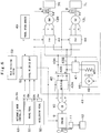
- the traveling drive unit 52 is provided with maximum value selecting parts 53, 54, an invalid output calculation unit 55, an acceleration output calculation unit 56 and autonomous mode invalid switches 57, 58.
- the acceleration command SAm from the accelerator operation sensor 50A and the acceleration command SAa from the autonomous mode controller 61 are input to the maximum value selecting part 53.
- the maximum value selecting part 53 forms an acceleration command selecting part, selects a larger one of the acceleration command SAm and the acceleration command SAa, and outputs the selected acceleration command SA.
- the larger value of the acceleration command SAm and the acceleration command SAa is a command for generating a large rate of acceleration (traveling drive force).
- the braking command SBm from the braking operation sensor 51A and the braking command SBa from the autonomous mode controller 61 are input to the maximum value selecting part 54.
- the maximum value selecting part 54 forms a deceleration command selecting part, selects a larger one of the braking command SBm and the braking command SBa, and outputs the selected braking command SB.
- the larger value of the braking command SBm and the braking command SBa is a command for generating a large rate of deceleration (braking force).
- the braking command SB selected from the maximum value selecting part 54 is input to the invalid output calculation unit 55.
- the invalid output calculation unit 55 prioritizes the braking command SB over the acceleration command SA, and therefore, outputs an invalid acceleration command SA0 to make the acceleration command SA invalid. Specifically, when the braking command SB is a value larger than a predetermined value, the invalid output calculation unit 55 outputs the invalid acceleration command SA0 to make the acceleration zero. On the other hand, when the braking command SB is a value smaller than a predetermined value, the invalid output calculation unit 55 stops the output of the invalid acceleration command SA0.
- the acceleration output calculation unit 56 calculates a final acceleration command SA based upon the acceleration command SA output from the maximum value selecting part 53 and the invalid acceleration command SA0. Specifically, when the invalid acceleration command SA0 is output, the acceleration output calculation unit 56 prioritizes the invalid acceleration command SA0 over the acceleration command SA, and therefore, stops the output of the acceleration command SA to make the acceleration zero. On the other hand, when the invalid acceleration command SA0 is not output, the acceleration output calculation unit 56 outputs the acceleration command SA output from the maximum value selecting part 53 as it is.
- the autonomous mode invalid switches 57, 58 switch validity and invalidity of the commands SAa, SBa input from the autonomous mode controller 61 corresponding to a mode selected by the mode selecting switch 59. That is, when the autonomous mode is selected by the mode selecting switch 59, the autonomous mode invalid switches 57, 58 make the acceleration command SAa and the braking command SBa valid, and input the commands SAa, SBa to the maximum value selecting parts 53, 54.
- the autonomous mode invalid switches 57, 58 make the acceleration command SAa and the braking command SBa invalid.
- the acceleration command SAa and the braking command SBa are not input to the maximum value selecting parts 53, 54. Therefore, the maximum value selecting part 53 selects the acceleration command SAm based upon the manual operation, which will be output as an acceleration command SA.
- the maximum value selecting part 54 selects the braking command SBm based upon the manual operation, which will be output as a braking command SB.
- the traveling drive unit 52 calculates travel torque, which is made to be generated in the wheel drive motors 13L, 13R, based upon the acceleration command SA and the braking command SB, and the wheel speed v from the wheel speed sensor 49. In addition, the traveling drive unit 52 controls the motor control device 41 to drive in the travel torque calculated by the wheel drive motors 13L, 13R.
- the autonomous mode controller 61 is provided with a control communication unit 62, a local location calculation unit 63, a behavior determination unit 64 and a travel control unit 65.
- the control communication unit 62 performs mutual communication with an external management station 71.
- the control communication unit 62 receives various kinds of operation commands V10 including information of the other vehicle, such as a traveling state or vehicle position of the other dump truck, for example, from the management station 71.
- the control communication unit 62 outputs the operation command V10 to the behavior determination unit 64.
- a mode signal M is input to the control communication unit 62 from the traveling drive unit 52, and local-vehicle information V11, such as a traveling state and vehicle position P0 of the dump truck 1, is input to the control communication unit 62 from the behavior determination unit 64.
- the control communication unit 62 determines the selected mode of the manual mode and the autonomous mode by the mode signal, and transmits the selected mode and the local-vehicle information V11 to the management station 71.
- the management station 71 can recognize whether the dump truck 1 operates in the manual mode or in the autonomous mode.
- the management station 71 can recognize in whose state of the traveling state and the stopping state the dump truck 1 is. Therefore, the management station 71 can output an operation command V10 corresponding to these conditions.
- the local location calculation unit 63 forms a vehicle location calculation unit that calculates a vehicle position P0 of a local vehicle.
- the local location calculation unit 63 is connected to, for example, a GPS antenna (not shown), and calculates a vehicle position P0 based upon a signal transmitted from a GPS satellite.
- the local location calculation unit 63 may be configured to be connected to the wheel speed sensor 49 and a gyroscope (not shown) provided in the dump truck 1, for example.
- the local location calculation unit 63 refers to map information of a working site including a loading area LA and a haul road HR, and the like, and calculates a vehicle position based upon an output signal of the wheel speed sensor 49 and an output signal of the gyroscope.
- the local location calculation unit 63 may calculate a vehicle position P0 by combining the position information based upon the GPS and the position information based upon the wheel speed sensor 49 and the like.
- the behavior determination unit 64 determines a traveling operation of the dump truck 1 in the autonomous mode. Specifically, the behavior determination unit 64 determines an operation of the dump truck 1 during the autonomous mode based upon the vehicle position P0 calculated by the local location calculation unit 63 and the operation command V10 received by the control communication unit 62, and outputs an operation command C including a target vehicle speed corresponding to the determined operation to a traveling control unit 65. In addition, the behavior determination unit 64 outputs the local-vehicle information V11 based upon a traveling state and a vehicle position P0 of the dump truck 1 corresponding to the operation command C to the control communication unit 62.
- the operations that will be determined by the behavior determination unit 64 include operations as follows. As shown in Fig. 8 , when the dump truck 1 is on the haul road HR, the behavior determination unit 64 performs, for example, an operation of advancing from the haul road HR into the loading area LA or an operation of retreating from the loading area LA into the haul road HR. In addition, when the dump truck 1 is within the loading area LA, the behavior determination unit 64 performs any of, for example, a queuing operation, an approaching operation and a haul operation within the loading area LA.
- the queuing operation is an operation that the dump truck 1 having advanced from the haul road HR into the loading area LA moves to a turnaround point TP.
- the approaching operation is an operation that the dump truck 1 retreats from the turnaround point TP and moves to an approaching position AP.
- the haul operation is an operation that the dump truck 1 moves from the approaching position AP to the haul road HR.
- the traveling control unit 65 forms a traveling trajectory trace unit (TRJ) that calculates an acceleration command SAa, a braking command SBa and a torque command Ta based upon a vehicle position P0 calculated by the local location calculation unit 63 and a predetermined travel trajectory.
- the traveling control unit 65 controls the steering actuator 33, the engine 9 and the motor control device 41 in the dump truck 1 based upon the operation command C from the behavior determination unit 64 and the vehicle position P0 calculated by the local location calculation unit 63, and performs an operation determined by the behavior determination unit 64.
- the traveling control unit 65 calculates a steering torque command Ta, an acceleration command SAa and a braking command SBa based upon the operation command C and the vehicle position P0 for the output.
- the traveling control unit 65 calculates a steering direction of the vehicle based upon the operation command C and the vehicle position P0 such that the dump truck 1 travels according to a predetermined travel trajectory.
- the traveling control unit 65 outputs the torque command Ta corresponding to the calculated steering direction to the steering actuator 33.
- the assist motor 36 in the steering actuator 33 is rotated in accordance with the torque command Ta, the output shaft 38 and the steering valve 31 are driven to control a steering angle ⁇ of the front wheels 6L, 6R.
- the traveling control unit 65 calculates a rate of acceleration and a rate of deceleration of the vehicle based upon the operation command C and the vehicle position P0 such that the dump truck 1 travels according to the predetermined travel trajectory.
- the traveling control unit 65 outputs an acceleration command SAa corresponding to the calculated rate of acceleration and a braking command SBa corresponding to the calculated rate of deceleration to the traveling drive unit 52.
- the traveling drive unit 52 controls the motor control device 41 based upon the acceleration command SAa and the braking command SBa to control acceleration and deceleration of the rear wheels 7L, 7R.
- the dump truck 1 according to the embodiment has the configuration as described above, and next, an operation thereof will be explained.
- the loading area LA is a place where transporting objects R such as crushed stones, earth and sand are loaded on the dump truck 1 by a hydraulic excavator EX.
- the hydraulic excavator EX moves within the loading area LA following progress of the loading work or the excavating work. Therefore, the loading area LA is a place where a movement trajectory of the dump truck 1 changes following the movement of the hydraulic excavator EX.
- the haul road HR is an improved path, and is provided to be connected to the loading area LA.
- the dump truck 1 advances into the loading area LA from an exterior through the haul road HR in an emptied state.
- the dump truck 1 retreats from the loading area LA through the haul road HR in a state where the transporting objects R are loaded, and take out the transporting object R to an external dumping area (not shown).
- the haul road HR is a place where the movement trajectory of the dump truck 1 becomes substantially constant.
- the dump truck 1 has the manual mode of traveling in response to the manual operation of an operator and the autonomous mode of traveling according to the operation command V10 from the management station 71. Therefore, an explanation will be first made of a traveling operation of the dump truck 1 in the manual mode.
- the steering actuator 33 when an operator rotates the steering handle 32 in the manual mode, the steering actuator 33 generates steering torque Tm by the operator, and further, assist torque T0 corresponding to the steering torque Tm, and rotates the output shaft 38 by combined torque T1 found by combining them.
- the steering valve 31 performs switch of supply and discharge of hydraulic oil and adjustment of a flow amount of hydraulic oil in response to rotation of the output shaft 38. Thereby, the steering cylinders 27L, 27R are driven to adjust a steering angle ⁇ of the front wheels 6R, 6L.
- the accelerator operation sensor 50A when an operator performs a depressing operation of the accelerator pedal 50, the accelerator operation sensor 50A outputs an acceleration command SAm corresponding to an operation amount (depressing amount) of the accelerator pedal 50 to the traveling drive unit 52.
- the braking operation sensor 51A outputs a braking command SBm corresponding to an operation amount (depressing amount) of the brake pedal 51 to the traveling drive unit 52.
- the traveling drive unit 52 calculates an acceleration command SA based upon the acceleration command SAm, and calculates a braking command SB based upon the braking command SBm.
- the traveling drive unit 52 controls the motor control device 41 based upon the acceleration command SA and the braking command SB.
- the motor control device 41 performs a power running operation or a regeneration operation of the wheel drive motors 13L, 13R based upon the acceleration command SA and the braking command SB to control a traveling drive of the rear wheels 7L, 7R.
- the dump truck 1 travels on the haul road HR or on the loading area LA based upon an operation of the steering handle 32, an operation of the accelerator pedal 50 and an operation of the brake pedal 51 by an operator.
- the dump truck 1 When the mode selecting switch 59 of the dump truck 1 is switched, the dump truck 1 is switched from the manual mode to the autonomous mode. As shown in Fig. 4 , in the autonomous mode, the autonomous mode controller 61 outputs a torque command Ta for steering to the steering actuator 33, and outputs an acceleration command SAa for accelerating the vehicle and a braking command SBa for decelerating the vehicle to the traveling drive unit 52.
- the steering actuator 33 drives the assist motor 36 based upon the torque command Ta from the autonomous mode controller 61, and rotates the output shaft 38 by the assist torque T0 in response to the torque command Ta.
- the steering valve 31 performs switch of supply and discharge of hydraulic oil and adjustment of a flow amount of hydraulic oil in response to rotation of the output shaft 38.
- the steering cylinders 27L, 27R are driven to adjust a steering angle ⁇ of the front wheels 6R, 6L.
- the traveling drive unit 52 calculates an acceleration command SA based upon the acceleration command SAa from the autonomous mode controller 61, and calculates a braking command SB based upon the braking command SBa from the autonomous mode controller 61.
- the traveling drive unit 52 controls the motor control device 41 based upon the acceleration command SA and the braking command SB.
- the motor control device 41 performs a power running operation or a regeneration operation of the wheel drive motors 13L, 13R based upon the acceleration command SA and the braking command SB to control a traveling drive of the rear wheels 7L, 7R.
- the dump truck 1 travels autonomously on the haul road HR or on the loading area LA based upon the torque command Ta, the acceleration command SAa and the braking command SBa from the autonomous mode controller 61.
- the dump truck 1 moves toward the loading area LA in a state where an operator gets in the dump truck 1, in some cases the dump truck 1 travels in the autonomous mode. In this state, the operator who has got in the dump truck 1 possibly desires to stop the dump truck 1.
- the machine control module in common between the autonomous mode and the manual mode is used, and in the autonomous mode, the manual operation is made invalid. Therefore, for stopping the dump truck 1 in the autonomous mode, it is necessary to perform a braking operation after switching from the autonomous mode to the manual mode, thus it causes a problem of difficulty of performing a quick stopping operation.
- the maximum value selecting part 53 in the traveling drive unit 52 compares the acceleration command SAm by the accelerator pedal 50 and the acceleration command SAa by the autonomous mode controller 61 to select a larger one thereof.
- the maximum value selecting part 54 in the traveling drive unit 52 compares the braking command SBm by the brake pedal 51 and the braking command SBa by the autonomous mode controller 61 to select a larger one thereof, which is output as the braking command SB.
- the accelerator output calculation unit 56 in the traveling drive unit 52 prioritizes the braking command SB selected by the maximum value selecting part 54 over the acceleration command SA selected by the maximum value selecting part 53 to make the acceleration command SA invalid.
- the traveling drive unit 52 outputs the braking command SB corresponding to the depressing amount of the brake pedal 51. Therefore, it is possible to stop the dump truck 1 during the autonomous mode by the depressing operation of the brake pedal 51 without switching from the autonomous mode to the manual mode.
- the steering system 21 can be controlled with the rotational operation of the steering handle 32 by the operator without switching from the autonomous mode to the manual mode, and it is possible to adjust the traveling direction of the dump truck 1 during the autonomous mode with the rotational operation of the steering handle 32. Further, the depressing operation of the accelerator pedal 50 enables the dump truck 1 during the autonomous mode to be accelerated.
- the maximum value selecting part 53 (acceleration command selecting part) in the traveling drive unit 52 selects a larger one of the acceleration command SAa input from the external input terminal 52A and the acceleration command SAm by the accelerator pedal 50 (acceleration operation device) as an acceleration command SA
- the maximum value selecting part 54 in the traveling drive unit 52 selects a larger one of the braking command SBa input from the external input terminal 52B and the braking command SBm by the brake pedal 51 (braking operation device) as a braking command SB. Therefore, the traveling drive unit 52 can accelerate or decelerate the vehicle based upon the acceleration command SA selected by the maximum value selecting part 53 and the braking command SB selected by the maximum value selecting part 54.
- the maximum value selecting part 54 selects a larger one of the braking command SBa input from the external input terminal 52B and the braking command SBm by the brake pedal 51 as the braking command SB. Therefore, for example, even during the autonomous traveling, operating the brake pedal 51 by an operator having got in the vehicle enables the maximum value selecting part 54 to select the braking command SBm by the brake pedal 51. As a result, it is possible to stop the vehicle by performing the manual operation of the brake pedal 51 even during the autonomous travel.
- the traveling drive unit 52 is provided with the external input terminals 52A, 52B, it is possible to add a function of the autonomous mode by inputting the acceleration command SAa and the braking command SBa for autonomous travel to the external input terminals 52A, 52B. That is, connecting the autonomous mode controller 61 to the external input terminals 52A, 52B in the traveling drive unit 52 enables the dump truck 1 capable of traveling in the autonomous mode to be configured. Therefore, components other than the autonomous mode controller 61 can be used in common between a vehicle for manual mode and a vehicle for autonomous mode to reduce the manufacturing costs.
- the dump truck 1 is provided with the steering handle 32 (steering operation device) that operates a traveling direction of a vehicle, the steering actuator 33 that adds the assist torque T0 (additional torque) to the steering torque Tm of the steering handle 32, and further, the steering system 21 that steers a vehicle based upon combined torque T1 by combining the steering torque Tm and the assist torque T0.
- the steering actuator 33 generates assist torque T0 (additional torque) based upon a torque command Ta from an exterior.
- the steering system 21 steers a vehicle based upon the combined torque T1 by combining the steering torque Tm and the assist torque T0.
- the steering actuator 33 is a power steering device
- the power steering device can generate assist torque T0 for assisting in the steering torque Tm at the time of performing the manual operation.
- the steering actuator 33 can generate assist torque T0 based upon the torque command Ta.
- the autonomous mode controller 61 causing a vehicle to travel according to a predetermined travel trajectory is connected to the external input terminals 52A, 52B in the traveling drive unit 52 and the steering actuator 33.
- the autonomous mode controller 61 is provided with the local location calculation unit 63 (vehicle location calculation unit) that calculates a position of a vehicle, and the traveling control unit 65 (traveling trajectory trace unit) that calculates an acceleration command SAa, a braking command SBa and a torque command Ta based upon a vehicle position P0 calculated by the local location calculation unit 63 and a predetermined travel trajectory. Therefore, a vehicle can autonomously travel according to the predetermined travel trajectory by connecting the autonomous mode controller 61 to the external input terminals 52A, 52B in the traveling drive unit 52 and the steering actuator 33.
- the mode selecting switch 59 is connected to the traveling drive unit 52. Therefore, the mode selecting switch 59 allows for input of the acceleration command SAa and the braking command SBa, whereby the traveling drive unit 52 can control a traveling drive of a vehicle based upon the acceleration command SAa and the braking command SBa. On the other hand, the mode selecting switch 59 prohibits the input of the acceleration command SAa and the braking command SBa, whereby the traveling drive unit 52 excludes the acceleration command SAa and the braking command SBa, thus making it possible to control a traveling drive of a vehicle based upon the manual operation.
- the steering actuator 33 switches validity and invalidity of the torque command Ta input from the autonomous mode controller 61 according to the selecting state by the mode selecting switch 59. Therefore, when the torque command Ta is made valid, it is possible to perform the steering by the autonomous travel, and when the torque command Ta is made invalid, it is possible to perform the steering by the manual operation.
- the steering actuator 33 is the power steering device for assisting in the steering torque Tm.
- the present invention is not limited thereto.
- the steering actuator 33 generates the assist torque T0 in response to the torque command Ta from the autonomous mode controller 61, and on the other hand, when the steering handle 32 is manually operated, the steering torque Tm may be transmitted to the output shaft 38 as it is without generation of the assist torque T0.
- the steering system 21 is provided with the steering mechanism 22 that steers the front wheels 6L, 6R by the steering cylinders 27L, 27R.
- the present invention is not limited thereto.
- a steering mechanism that converts rotational torque of the output shaft 38 into a steering force of the front wheels 6L, 6R through a steering gear mechanism composed of a rack and a pinion.
- the dump truck 1 is provided with the autonomous mode controller 61.
- the present invention is not limited thereto.
- a dump truck may be configured to be able to perform only a manual operation without using the autonomous mode controller 61.
Landscapes
- Engineering & Computer Science (AREA)
- Transportation (AREA)
- Mechanical Engineering (AREA)
- Automation & Control Theory (AREA)
- Chemical & Material Sciences (AREA)
- Combustion & Propulsion (AREA)
- Human Computer Interaction (AREA)
- Aviation & Aerospace Engineering (AREA)
- Radar, Positioning & Navigation (AREA)
- Remote Sensing (AREA)
- Physics & Mathematics (AREA)
- General Physics & Mathematics (AREA)
- Arrangement Or Mounting Of Propulsion Units For Vehicles (AREA)
- Electric Propulsion And Braking For Vehicles (AREA)
- Control Of Driving Devices And Active Controlling Of Vehicle (AREA)
- Business, Economics & Management (AREA)
- Health & Medical Sciences (AREA)
- Artificial Intelligence (AREA)
- Evolutionary Computation (AREA)
- Game Theory and Decision Science (AREA)
- Medical Informatics (AREA)
- Traffic Control Systems (AREA)
- Steering Control In Accordance With Driving Conditions (AREA)
- Regulating Braking Force (AREA)
Abstract
Description
- The present invention relates to haulage vehicles such as a dump truck.
- As haulage vehicles, there is known a dump truck that carries transporting objects such as crushed stones at a working site like mines (for example, refer to Patent Document 1). The dump truck described in
Patent Document 1 has an autonomous traveling mode of autonomously traveling based upon various kinds of commands and a manual traveling mode of traveling by an operation of an operator in the truck, and travels in one of the modes selected by a mode selecting signal. - Patent Document 1:
Japanese Patent Laid-Open No. Hei 8-76846 A - Incidentally, the haulage vehicle described in
Patent Document 1 is provided with a machine control module that is operable to correspond to the selected mode out of the autonomous traveling mode and the manual traveling mode. The machine control module receives a steering signal and a speed requirement signal from a navigator in the autonomous traveling mode and receives a steering signal and a speed requirement signal from a steering wheel, an accelerator pedal and a brake pedal in the manual traveling mode. The machine control module controls a steering angle of a vehicle body and a vehicle body speed in response to the received steering signal and speed requirement signal. - However, the dump truck described in
Patent Document 1 operates in one of the autonomous traveling mode and the manual traveling mode. Therefore, even when an operator performs an acceleration operation or a braking operation (retard operation), for example, in a state where the autonomous traveling mode is selected, these manual operations become invalid. As a result, there is a problem that even when the operator who has got in the vehicle performs the braking operation during the autonomous travel, the operator cannot stop the vehicle. - In addition, the dump truck described in
Patent Document 1 inputs a signal of a manual operation to the machine control module for performing the autonomous travel. Therefore, there is a tendency that it is difficult to add a function of the autonomous travel to the existing dump truck operable on a basis of the manual operation. - The present invention is made in view of the aforementioned problems in the conventional art, and an object of the present invention is to provide a haulage vehicle that can perform a manual operation even during an autonomous travel.
- For solving the aforementioned problems, according to the present invention, a haulage vehicle comprises: an acceleration operation device that operates acceleration of a vehicle; a braking operation device that operates a brake of the vehicle; and a traveling drive unit that causes the vehicle to travel based upon an acceleration command by the acceleration operation device and a braking command by the braking operation device, characterized in that: the traveling drive unit comprises: an external input terminal for inputting another acceleration command and another braking command from an exterior; an acceleration command selecting unit that selects a larger acceleration command by comparing the other acceleration command input from the external input terminal and the acceleration command by the acceleration operation device; and a braking command selecting unit that selects a larger braking command by comparing the other braking command input from the external input terminal and the braking command by the braking operation device, wherein a traveling drive of the vehicle is controlled based upon the acceleration command selected by the acceleration command selecting unit and the braking command selected by the braking command selecting unit.
- According to the present invention, the acceleration command selecting unit selects the larger acceleration command out of the other acceleration command input from the external input terminal and the acceleration command by the acceleration operation device, and the braking command selecting unit selects the larger braking command out of the other braking command from the external input terminal and the braking command input by the braking operation device. Therefore, the traveling drive unit can accelerate or decelerate the vehicle based upon the acceleration command selected by the acceleration command selecting unit and the braking command selected by the braking command selecting unit.
- In addition, the braking command selecting unit selects the larger braking command out of the other braking command input from the external input terminal and the braking command by the braking operation device. Therefore, for example, even during the autonomous travel, the operation of the braking operation device by the operator who has got in the vehicle enables the braking command selecting unit to select the braking command by the braking operation device. As a result, it is possible to perform the manual operation even during the autonomous travel.
- Further, since the traveling drive unit is provided with the external input terminal, a function of the autonomous traveling mode can be added by inputting the acceleration command and the braking command for autonomous travel to the external input terminal.
-
-
Fig. 1 is a front view showing a dump truck according to an embodiment in the present invention. -
Fig. 2 is a perspective view showing the dump truck with a vessel being removed. -
Fig. 3 is an entire configuration diagram showing a steering system and a travel driving system in the dump truck. -
Fig. 4 is a block diagram showing an entire configuration of the dump truck. -
Fig. 5 is a block diagram showing a steering actuator inFig. 4 . -
Fig. 6 is an electrical circuit diagram showing an electrical system for traveling drive in the dump truck. -
Fig. 7 is a block diagram showing a traveling drive unit inFig. 6 . -
Fig. 8 is an explanatory diagram showing a state where the dump truck travels on a haul road and within a loading area. - Hereinafter, a haulage vehicle according to an embodiment of the present invention will be in detail explained with reference to the accompanying drawings, by taking a dump truck as an example.
- In the figure, a
dump truck 1 is a large-sized haulage vehicle, which includes avehicle body 2, avessel 3, acab 5,front wheels rear wheels - As shown in
Fig. 1 andFig. 2 , thevehicle body 2 forms a frame structure. Thevessel 3 as a loading platform is mounted on an upper side of thevehicle body 2 to be capable of being tilted (lifted) on a basis of a rear portion side of thevehicle body 2 as a fulcrum by ahoist cylinder 4. - The
cab 5 is provided on an upper side of a front portion of thevehicle body 2 to be located in the front side of thevessel 3. Thecab 5 defines therein an operator' s room where an operator of thedump truck 1 gets in/off. An operator's seat and an engine switch (any thereof is not shown) are provided within thecab 5, and further, asteering handle 32, anaccelerator pedal 50 and abrake pedal 51 to be described later are provided. - Left and right
front wheels vehicle body 2. Thefront wheel 6L is arranged in the left side of thevehicle body 2 and thefront wheel 6R is arranged in the right side of thevehicle body 2. The left and rightfront wheels steering cylinders front wheels rear wheels front wheels steering cylinders dump truck 1 operates thesteering handle 32 to be described later. - The
rear wheels vehicle body 2. Therear wheel 7L is arranged in the left side of thevehicle body 2 and therear wheel 7R is arranged in the right side of thevehicle body 2. The left and rightrear wheels dump truck 1 and are driven bywheel drive motors dump truck 1 is driven to travel by driving and rotating the left and rightrear wheels - As shown in
Fig. 6 , thefront wheels rear wheels mechanical braking devices 8 such as disc brakes. Thebraking operation device 8 acts as a so-called parking brake, and atraveling drive unit 52 controls a braking state and a brake releasing state of thebraking operation device 8. Thebraking operation device 8 becomes in the braking state when thedump truck 1 stops, and holds the stopping state of thedump truck 1. On the other hand, thebraking operation device 8 becomes in the brake releasing state when thedump truck 1 travels, and allows for a forward travel or backward travel of thedump truck 1. - The
engine 9 is provided in thevehicle body 2 to be positioned under thecab 5. Theengine 9 is configured by, for example, a large-sized diesel engine. Theengine 9 drives amain power generator 10 to generate three-phase AC power, and drives anauxiliary power generator 11 for DC. Theauxiliary power generator 11 is connected to abattery 12 as a power source of thetraveling drive unit 52, anautonomous mode controller 61 and the like to charge thebattery 12. In addition, theengine 9 rotates ahydraulic pump 29 to be described later and the like. - The
wheel drive motors vehicle body 2 through an accelerator housing (not shown). Thewheel drive motor 13L is connected mechanically to the leftrear wheel 7L through arotational shaft 14 to drive therear wheel 7L. Thewheel drive motor 13R is connected mechanically to the rightrear wheel 7R through therotational shaft 14 to drive therear wheel 7R. Thewheel drive motors motor control device 41 from themain power generator 10. - The respective
wheel drive motors motor control device 41, and are respectively driven and rotated independently. Themotor control device 41, based upon a control signal from the travelingdrive unit 52 to be described later, controls rotating speeds of the left and rightrear wheels rear wheels - Next, an explanation will be made of the configuration of a
steering system 21 mounted on thedump truck 1 with reference toFig. 3 to Fig. 5 . - The
steering system 21 changes a direction of thefront wheels steering system 21 is provided with asteering mechanism 22, and ahydraulic circuit 28 for driving thesteering cylinders steering mechanism 22. - The
steering mechanism 22 includesspindles steering cylinders - The
spindles vehicle body 2, and rotatably support thefront wheels king pin 24 extending in the upper-lower direction is provided to be integral with theleft spindle 23L, and thespindle 23L is supported to be rotatable in the front-rear direction at the center of theking pin 24. Aknuckle arm 25L extending backward is provided to be integral with thespindle 23L. - The
right spindle 23R is formed to be bilaterally symmetric to theleft spindle 23L. Therefore, theking pin 24 extending in the upper-lower direction is provided to be integral with theright spindle 23R as similar to theleft spindle 23L, and thespindle 23R is supported to be rotatable in the front-rear direction at the center of theking pin 24. Aknuckle arm 25R is provided to be integral with thespindle 23R. - Tip portions of the
knuckle arms tie rod 26. Thetie rod 26 and theknuckle arms spindles front wheels - The
steering cylinders hydraulic pump 29 to be described later. Theleft steering cylinder 27L has a base portion attached to a cylinder bracket of the trailing arm, and a tip portion jointed to the midway position of theknuckle arm 25L in the length direction. Similarly, theright steering cylinder 27R has a base portion attached to the cylinder bracket of the trailing arm, and a tip portion jointed to the midway position of theknuckle arm 25R in the length direction. - When one of the
steering cylinders steering cylinders front wheels - As shown in
Fig. 3 , thehydraulic circuit 28 includes thehydraulic pump 29 and a steeringvalve 31, and controls supply and discharge of the hydraulic oil to and from thesteering cylinders steering handle 32. - The
hydraulic pump 29 is provided near theengine 9, and is driven/rotated by theengine 9. Thehydraulic pump 29 is connected to ahydraulic oil tank 30 that is attached to a lateral side of thevehicle body 2, and delivers hydraulic oil to thesteering cylinders - The steering
valve 31 performs switching control of supply and discharge of hydraulic oil to and from thesteering cylinders steering handle 32. The steeringvalve 31 is configured using, for example, a spool valve or the like. The steeringvalve 31 is jointed to the steering handle 32 through asteering actuator 33, switches supply and discharge of the hydraulic oil corresponding to a rotating direction of thesteering handle 32, and controls a flow amount of hydraulic oil corresponding to a rotation angle of thesteering handle 32. - The steering handle 32 (steering wheel) is provided in the
cab 5, a steering operation of which is performed by an operator. The steering handle 32 configures a steering operation device that operates the traveling direction of a vehicle, and is gripped by the operator to rotate acolumn shaft 32A to left and right, thus performing a steering operation of the vehicle. It should be noted that the steering operation device is not limited to the steering handle 32 rotated by an operator, but may be configured by a lever operable to be tilted/lifted in the steering direction, for example. - The steering
actuator 33 is attached to thecolumn shaft 32A, and configures a power steering device to assist in steering torque Tm acting on thesteering handle 32. As shown inFig. 5 , the steeringactuator 33 includes atorque sensor 34 that detects the steering torque Tm, aspeed reduction mechanism 35, anassist motor 36 composed of an electric motor, and anEPS controller 37 for driving theassist motor 36. - The
EPS controller 37 calculates assist torque T0 based upon the steering torque Tm detected by thetorque sensor 34, and supplies a drive current for generating the assist torque T0 to the assistmotor 36. Theassist motor 36 is driven based upon the drive current supplied from theEPS controller 37, and adds the assist torque T0 as additional torque to anoutput shaft 38 through thespeed reduction mechanism 35. As a result, theoutput shaft 38 is rotated by the combined torque T1 (T1 = Tm + T0) by combining the steering torque Tm and the assist torque T0 to perform switch of supply and discharge of hydraulic oil and adjustment of a flow mount of hydraulic oil by the steeringvalve 31. - A
steering angle sensor 39 detects a steering angle θ of theleft front wheel 6L, for example. Thesteering angle sensor 39 is configured by, for example, an electromagnetic pickup rotation angle detector composed of a haul element and a magnet or an optical rotation angle detector composed of a light emitter and an optical receiver. - Here, for example, when the
front wheel 6L is directed in a straight-ahead traveling direction of a vehicle, that is, when thefront wheel 6L is in a straight-ahead state in parallel to the front-rear direction, the steering angle θ is zero (θ = 0 degrees). When thefront wheel 6L is inclined in a direction where a vehicle takes a left turn, the steering angle θ becomes a positive value (θ > 0 degrees), and when thefront wheel 6L is inclined in a direction where a vehicle takes a right turn, the steering angle θ becomes a negative value (θ < 0 degrees). Therefore, thesteering angle sensor 39 outputs a steering angle signal corresponding to the steering angle θ of thefront wheel 6L to theEPS controller 37. It should be noted that thesteering angle sensor 39 may detect a steering angle of theright front wheel 6R. - An
autonomous mode controller 61 is connected to theEPS controller 37 through anexternal input terminal 33A of thesteering actuator 33, and a torque command Ta is input to theEPS controller 37 from theautonomous mode controller 61 to perform the autonomous steering. In addition thereto, a travelingdrive unit 52 is connected to theEPS controller 37, and a mode signal M indicating a mode selected out of the manual mode and the autonomous mode is input to theEPS controller 37 from the travelingdrive unit 52. - When the manual mode is selected by the mode signal M, the
EPS controller 37 makes the torque command Ta from theautonomous mode controller 61 invalid. Then, theEPS controller 37 calculates assist torque T0 based upon the steering torque Tm detected by thetorque sensor 34, and supplies a drive current to the assistmotor 36 to generate the assist torque T0. - On the other hand, when the autonomous mode is selected by the mode signal M, the
EPS controller 37 makes the torque command Ta from theautonomous mode controller 61 valid. Then, theEPS controller 37 calculates assist torque T0 based upon the torque command Ta from theautonomous mode controller 61 and a steering angle θ by thesteering angle sensor 39, and supplies a drive current to the assistmotor 36 to generate the assist torque T0. - Next, an explanation will be made of an electric system for travel and drive mounted on the
dump truck 1 with reference toFig. 4 ,Fig. 6 andFig. 7 . - The
motor control device 41 controls the travelingdrive unit 52 to be described later, and a power running operation and a regeneration operation of thewheel drive motors motor control device 41 is positioned in the lateral side of thecab 5, and is configured by a power distribution switchboard provided to rise on adeck portion 2A of thevehicle body 2, and the like. As shown inFig. 6 , themotor control device 41 includes aconverter 42 andinverters 44. - The
converter 42 is configured by using a rectifier cell such as diode and thyristor, and includes arectifier 42A that performs full-wave rectification of AC power and a smoothingcapacitor 42B connected to the latter stage of therectifier 42A to smooth the power waveform. Theconverter 42 is connected to the output side of themain power generator 10 to convert three-phase AC power of U phase, V phase and W phase output from themain power generator 10 into DC power of P phase and N phase. Therefore, theconverter 42 configures a DC power source together with themain power generator 10. Theconverter 42 is connected to theinverters 44 by using a pair ofDC buses - The
inverter 44 is configured by using a plurality of switching elements (not shown) using, for example, a transistor, a thyristor or an insulating gate bipolar transistor (IGBT). Theinverters 44 are respectively connected to thewheel drive motors drive unit 52. - At the traveling of the
dump truck 1, theinverters 44 convert the DC power into three-phase AC power of a variable frequency to perform the power running operations of thewheel drive motors inverter 44 controls an on/off operation of the switching element, and thereby, converts the DC power output from theconverter 42 into the three-phase AC power of U phase, V phase and W phase and supplies this three-phase AC power to thewheel drive motors - On the other hand, at the decelerating of the
dump truck 1, theinverters 44 convert three-phase AC power into DC power to perform the regeneration of thewheel drive motors inverter 44 controls an on/off operation of the switching element, and thereby, converts an electromotive force of the three-phase AC power regenerated in thewheel drive motors resistors 45. - The
resistors 45 are connected to theDC buses converter 42 and theinverters 44. Theresistors 45 are respectively disposed ingrid boxes 46 in an angular cylindrical shape, and generate heat in response to the DC power supplied from theinverters 44, and consumes the electromotive force regenerated in thewheel drive motors - As shown in
Fig. 2 , thegrid boxes 46 are positioned at the opposite side to thecab 5 at the center of themotor control device 41 in the left-right direction, and are provided to be stacked on thedeck portion 2A of thevehicle body 2. Theresistors 45 are respectively accommodated in the plurality ofgrid boxes 46, and the plurality ofresistors 45 are connected to theDC buses - As shown in
Fig. 6 , achopper 47 is provided between theresistor 45 and theDC buses chopper 47 is configured by using a switching element of various types using a semiconductor, for example. At the decelerating of thedump truck 1, thechopper 47 reduces the DC voltage applied to theDC buses chopper 47 controls an on/off operation of the switching element, and thereby, reduces the regeneration power by thewheel drive motors resistor 45. As a result, a current flows in theresistor 45, and theresistor 45 converts electrical energy into thermal energy. On the other hand, at the traveling of thedump truck 1, thechopper 47 becomes in a disconnection state to electrically block off connection between theDC buses resistor 45. It should be noted that a switch for switching the connection and disconnection may be provided between theresistor 45 and theDC buses chopper 47. -
Blowers 48 are mounted to thegrid boxes 46. Theblower 48 is configured by an electric motor that is driven by power supply from theDC buses blower 48 is driven, for example, in response to a heat generator operation of theresistor 45 to supply cooling air toward theresistor 45. - A
wheel speed sensor 49 is disposed, for example, near therotational shaft 14, detects a rotational speed of therotational shaft 14 of thewheel drive motors rear wheels rotational shaft 14 in a predetermined reduction ratio predetermined by a multi-step planetary reduction mechanism (for example, a reduction ratio of approximately 30 to 40) to the rotational speed of thewheel drive motors rear wheels wheel speed sensor 49 detects the rotational speed of therotational shaft 14 to calculate a wheel speed v (traveling speed of the vehicle) of therear wheels wheel speed sensor 49 is connected to the travelingdrive unit 52. - The
accelerator pedal 50 forms an acceleration operation device that operates acceleration of the vehicle. Theaccelerator pedal 50 is provided in thecab 5, and is operated to be depressed by an operator. Thewheel drive motors accelerator pedal 50 to accelerate thedump truck 1. Theaccelerator pedal 50 is provided with anaccelerator operation sensor 50A that detects the operation amount. Theaccelerator operation sensor 50A is configured by, for example, an angular sensor, a potentiometer or the like, and outputs an acceleration command SAm corresponding to an operation amount (depressing amount) of theaccelerator pedal 50. It should be noted that the acceleration operation device is not limited to theaccelerator pedal 50 that is depressed by an operator, and may be configured by a lever that is manually operated or the like. - The
brake pedal 51 forms a braking operation device that operates a brake of the vehicle. Thebrake pedal 51 is disposed in thecab 5 and is operated to be depressed by an operator. Thewheel drive motors brake pedal 51 to decelerate thedump truck 1. Thebrake pedal 51 is provided with abraking operation sensor 51A that detects an operation amount thereof. Thebraking operation sensor 51A is configured by, for example, an angular sensor, a potentiometer or the like, and outputs a braking command SBm corresponding to an operation amount (depressing amount) of thebrake pedal 51. It should be noted that the braking operation device is not limited to thebrake pedal 51 that is depressed by an operator, and may be configured by a lever that is manually operated or the like. - An outside side of each of the
accelerator operation sensor 50A and thebraking operation sensor 51A is connected to the travelingdrive unit 52 to be described later. The travelingdrive unit 52 determines whether thedump truck 1 is in an acceleration or deceleration state based upon the acceleration command SAm from theaccelerator operation sensor 50A and the braking command SBm from thebraking operation sensor 51A. - The traveling
drive unit 52 is configured by, for example, a microcomputer and the like, and is a control device that causes the vehicle to travel based upon the acceleration command SAm from theaccelerator pedal 50 and the braking command SBm from thebrake pedal 51. The travelingdrive unit 52 is connected to themotor control device 41 and the like, outputs a control signal according to a travel state of thedump truck 1 and the like, and controls to switch the switching elements in theinverters 44 by this control signal. Specifically, at the accelerating of thedump truck 1, the travelingdrive unit 52 controls the switching elements in theinverters 44 in such a way as to convert the DC power from themain power generator 10 into three-phase AC power. On the other hand, at the decelerating of thedump truck 1, the travelingdrive unit 52 controls the switching elements in theinverters 44 in such a way as to convert the electromotive power composed of three-phase AC power generated in thewheel drive motors - Further, the traveling
drive unit 52 is connected to each of thechopper 47 and theblower 48, switches connection/disconnection between theresistor 45 and theDC buses blower 48. Specifically, at the accelerating of thedump truck 1, the travelingdrive unit 52 controls thechopper 47 to be in a stop state to block off an electrical connection between theresistor 45 and theDC buses drive unit 52 stops power consumption by theresistor 45 and stops theblower 48. - On the other hand, at the decelerating of the
dump truck 1, the travelingdrive unit 52 controls thechopper 47 to be in a drive state to establish an electrical connection between theresistor 45 and theDC buses drive unit 52 allows for power consumption by theresistor 45 and drives theblower 48 to supply cooling air toward theresistor 45. - The
accelerator operation sensor 50A and thebraking operation sensor 51A are connected to the travelingdrive unit 52, and the acceleration command SAm from theaccelerator operation sensor 50A and the braking command SBm from thebraking operation sensor 51A are input to the travelingdrive unit 52. In addition, theautonomous mode controller 61 is connected to the travelingdrive unit 52 through theexternal input terminals 52A, 52B. The acceleration command SAa from theautonomous mode controller 61 is input to the travelingdrive unit 52 through theexternal input terminal 52A, and the braking command SBa from theautonomous mode controller 61 is input to the travelingdrive unit 52 through the external input terminal 52B. Further, amode selecting switch 59 that selects one of the manual mode and the autonomous mode is connected to the travelingdrive unit 52. - When the manual mode is selected by the
mode selecting switch 59, the travelingdrive unit 52 calculates an acceleration command SA based upon the acceleration command SAm from theaccelerator operation sensor 50A and calculates a braking command SB based upon the braking command SBm from thebraking operation sensor 51A. The travelingdrive unit 52 controls themotor control device 41 based upon the acceleration command SA and the braking command SB. - On the other hand, when the autonomous mode is selected by the
mode selecting switch 59, the travelingdrive unit 52 calculates an acceleration command SA based upon the acceleration command SAa from theautonomous mode controller 61 and calculates a braking command SB based upon the braking command SBa from theautonomous mode controller 61. The travelingdrive unit 52 controls themotor control device 41 based upon the acceleration command SA and the braking command SB. - As shown in
Fig. 7 , the travelingdrive unit 52 is provided with maximumvalue selecting parts output calculation unit 55, an accelerationoutput calculation unit 56 and autonomous modeinvalid switches - The acceleration command SAm from the
accelerator operation sensor 50A and the acceleration command SAa from theautonomous mode controller 61 are input to the maximumvalue selecting part 53. The maximumvalue selecting part 53 forms an acceleration command selecting part, selects a larger one of the acceleration command SAm and the acceleration command SAa, and outputs the selected acceleration command SA. At this time, the larger value of the acceleration command SAm and the acceleration command SAa is a command for generating a large rate of acceleration (traveling drive force). - The braking command SBm from the
braking operation sensor 51A and the braking command SBa from theautonomous mode controller 61 are input to the maximumvalue selecting part 54. The maximumvalue selecting part 54 forms a deceleration command selecting part, selects a larger one of the braking command SBm and the braking command SBa, and outputs the selected braking command SB. At this time, the larger value of the braking command SBm and the braking command SBa is a command for generating a large rate of deceleration (braking force). - The braking command SB selected from the maximum
value selecting part 54 is input to the invalidoutput calculation unit 55. The invalidoutput calculation unit 55 prioritizes the braking command SB over the acceleration command SA, and therefore, outputs an invalid acceleration command SA0 to make the acceleration command SA invalid. Specifically, when the braking command SB is a value larger than a predetermined value, the invalidoutput calculation unit 55 outputs the invalid acceleration command SA0 to make the acceleration zero. On the other hand, when the braking command SB is a value smaller than a predetermined value, the invalidoutput calculation unit 55 stops the output of the invalid acceleration command SA0. - The acceleration
output calculation unit 56 calculates a final acceleration command SA based upon the acceleration command SA output from the maximumvalue selecting part 53 and the invalid acceleration command SA0. Specifically, when the invalid acceleration command SA0 is output, the accelerationoutput calculation unit 56 prioritizes the invalid acceleration command SA0 over the acceleration command SA, and therefore, stops the output of the acceleration command SA to make the acceleration zero. On the other hand, when the invalid acceleration command SA0 is not output, the accelerationoutput calculation unit 56 outputs the acceleration command SA output from the maximumvalue selecting part 53 as it is. - The autonomous mode
invalid switches autonomous mode controller 61 corresponding to a mode selected by themode selecting switch 59. That is, when the autonomous mode is selected by themode selecting switch 59, the autonomous modeinvalid switches value selecting parts - On the other hand, when the manual mode is selected by the
mode selecting switch 59, the autonomous modeinvalid switches value selecting parts value selecting part 53 selects the acceleration command SAm based upon the manual operation, which will be output as an acceleration command SA. Likewise, the maximumvalue selecting part 54 selects the braking command SBm based upon the manual operation, which will be output as a braking command SB. - The traveling
drive unit 52 calculates travel torque, which is made to be generated in thewheel drive motors wheel speed sensor 49. In addition, the travelingdrive unit 52 controls themotor control device 41 to drive in the travel torque calculated by thewheel drive motors - Next, an explanation will be made of the
autonomous mode controller 61 for autonomous travel of thedump truck 1 with reference toFig. 4 andFig. 8 . - As shown in
Fig. 4 , theautonomous mode controller 61 is provided with acontrol communication unit 62, a locallocation calculation unit 63, abehavior determination unit 64 and atravel control unit 65. - The
control communication unit 62 performs mutual communication with anexternal management station 71. Thecontrol communication unit 62 receives various kinds of operation commands V10 including information of the other vehicle, such as a traveling state or vehicle position of the other dump truck, for example, from themanagement station 71. Thecontrol communication unit 62 outputs the operation command V10 to thebehavior determination unit 64. - In addition, a mode signal M is input to the
control communication unit 62 from the travelingdrive unit 52, and local-vehicle information V11, such as a traveling state and vehicle position P0 of thedump truck 1, is input to thecontrol communication unit 62 from thebehavior determination unit 64. Thecontrol communication unit 62 determines the selected mode of the manual mode and the autonomous mode by the mode signal, and transmits the selected mode and the local-vehicle information V11 to themanagement station 71. Thereby, themanagement station 71 can recognize whether thedump truck 1 operates in the manual mode or in the autonomous mode. In addition thereto, themanagement station 71 can recognize in whose state of the traveling state and the stopping state thedump truck 1 is. Therefore, themanagement station 71 can output an operation command V10 corresponding to these conditions. - The local
location calculation unit 63 forms a vehicle location calculation unit that calculates a vehicle position P0 of a local vehicle. Specifically, the locallocation calculation unit 63 is connected to, for example, a GPS antenna (not shown), and calculates a vehicle position P0 based upon a signal transmitted from a GPS satellite. Further, the locallocation calculation unit 63 may be configured to be connected to thewheel speed sensor 49 and a gyroscope (not shown) provided in thedump truck 1, for example. In this case, the locallocation calculation unit 63 refers to map information of a working site including a loading area LA and a haul road HR, and the like, and calculates a vehicle position based upon an output signal of thewheel speed sensor 49 and an output signal of the gyroscope. It should be noted that the locallocation calculation unit 63 may calculate a vehicle position P0 by combining the position information based upon the GPS and the position information based upon thewheel speed sensor 49 and the like. - The
behavior determination unit 64 determines a traveling operation of thedump truck 1 in the autonomous mode. Specifically, thebehavior determination unit 64 determines an operation of thedump truck 1 during the autonomous mode based upon the vehicle position P0 calculated by the locallocation calculation unit 63 and the operation command V10 received by thecontrol communication unit 62, and outputs an operation command C including a target vehicle speed corresponding to the determined operation to a travelingcontrol unit 65. In addition, thebehavior determination unit 64 outputs the local-vehicle information V11 based upon a traveling state and a vehicle position P0 of thedump truck 1 corresponding to the operation command C to thecontrol communication unit 62. - The operations that will be determined by the
behavior determination unit 64 include operations as follows. As shown inFig. 8 , when thedump truck 1 is on the haul road HR, thebehavior determination unit 64 performs, for example, an operation of advancing from the haul road HR into the loading area LA or an operation of retreating from the loading area LA into the haul road HR. In addition, when thedump truck 1 is within the loading area LA, thebehavior determination unit 64 performs any of, for example, a queuing operation, an approaching operation and a haul operation within the loading area LA. - Here, the queuing operation is an operation that the
dump truck 1 having advanced from the haul road HR into the loading area LA moves to a turnaround point TP. The approaching operation is an operation that thedump truck 1 retreats from the turnaround point TP and moves to an approaching position AP. The haul operation is an operation that thedump truck 1 moves from the approaching position AP to the haul road HR. - The traveling
control unit 65 forms a traveling trajectory trace unit (TRJ) that calculates an acceleration command SAa, a braking command SBa and a torque command Ta based upon a vehicle position P0 calculated by the locallocation calculation unit 63 and a predetermined travel trajectory. The travelingcontrol unit 65 controls thesteering actuator 33, theengine 9 and themotor control device 41 in thedump truck 1 based upon the operation command C from thebehavior determination unit 64 and the vehicle position P0 calculated by the locallocation calculation unit 63, and performs an operation determined by thebehavior determination unit 64. As shown inFig. 4 , the travelingcontrol unit 65 calculates a steering torque command Ta, an acceleration command SAa and a braking command SBa based upon the operation command C and the vehicle position P0 for the output. - Specifically, the traveling
control unit 65 calculates a steering direction of the vehicle based upon the operation command C and the vehicle position P0 such that thedump truck 1 travels according to a predetermined travel trajectory. The travelingcontrol unit 65 outputs the torque command Ta corresponding to the calculated steering direction to thesteering actuator 33. Thereby, since theassist motor 36 in thesteering actuator 33 is rotated in accordance with the torque command Ta, theoutput shaft 38 and the steeringvalve 31 are driven to control a steering angle θ of thefront wheels - In addition, the traveling
control unit 65 calculates a rate of acceleration and a rate of deceleration of the vehicle based upon the operation command C and the vehicle position P0 such that thedump truck 1 travels according to the predetermined travel trajectory. The travelingcontrol unit 65 outputs an acceleration command SAa corresponding to the calculated rate of acceleration and a braking command SBa corresponding to the calculated rate of deceleration to the travelingdrive unit 52. Thereby, the travelingdrive unit 52 controls themotor control device 41 based upon the acceleration command SAa and the braking command SBa to control acceleration and deceleration of therear wheels - The
dump truck 1 according to the embodiment has the configuration as described above, and next, an operation thereof will be explained. - As shown in
Fig. 8 , a mine such as a quarry site is provided with the loading area LA and the haul road HR. Here, the loading area LA is a place where transporting objects R such as crushed stones, earth and sand are loaded on thedump truck 1 by a hydraulic excavator EX. In this loading area LA, an excavating work for excavating crushed stones and the like by the hydraulic excavator EX together with the loading work of transporting objects R onto thedump truck 1 are performed. Here, the hydraulic excavator EX moves within the loading area LA following progress of the loading work or the excavating work. Therefore, the loading area LA is a place where a movement trajectory of thedump truck 1 changes following the movement of the hydraulic excavator EX. - The haul road HR is an improved path, and is provided to be connected to the loading area LA. The
dump truck 1 advances into the loading area LA from an exterior through the haul road HR in an emptied state. Thedump truck 1 retreats from the loading area LA through the haul road HR in a state where the transporting objects R are loaded, and take out the transporting object R to an external dumping area (not shown). As long as, for example, obstacles and the like do not exist on the haul road HR, thedump truck 1 travels on the haul road HR according to a predetermined, given movement trajectory. Therefore, the haul road HR is a place where the movement trajectory of thedump truck 1 becomes substantially constant. - The
dump truck 1 has the manual mode of traveling in response to the manual operation of an operator and the autonomous mode of traveling according to the operation command V10 from themanagement station 71. Therefore, an explanation will be first made of a traveling operation of thedump truck 1 in the manual mode. - As shown in
Fig. 3 to Fig. 5 , when an operator rotates the steering handle 32 in the manual mode, the steeringactuator 33 generates steering torque Tm by the operator, and further, assist torque T0 corresponding to the steering torque Tm, and rotates theoutput shaft 38 by combined torque T1 found by combining them. The steeringvalve 31 performs switch of supply and discharge of hydraulic oil and adjustment of a flow amount of hydraulic oil in response to rotation of theoutput shaft 38. Thereby, thesteering cylinders front wheels - Further, as shown in
Fig. 4 ,Fig. 6 andFig. 7 , when an operator performs a depressing operation of theaccelerator pedal 50, theaccelerator operation sensor 50A outputs an acceleration command SAm corresponding to an operation amount (depressing amount) of theaccelerator pedal 50 to the travelingdrive unit 52. Likewise, when an operator performs a depressing operation of thebrake pedal 51, thebraking operation sensor 51A outputs a braking command SBm corresponding to an operation amount (depressing amount) of thebrake pedal 51 to the travelingdrive unit 52. - The traveling
drive unit 52 calculates an acceleration command SA based upon the acceleration command SAm, and calculates a braking command SB based upon the braking command SBm. The travelingdrive unit 52 controls themotor control device 41 based upon the acceleration command SA and the braking command SB. Themotor control device 41 performs a power running operation or a regeneration operation of thewheel drive motors rear wheels - Thereby, the
dump truck 1 travels on the haul road HR or on the loading area LA based upon an operation of thesteering handle 32, an operation of theaccelerator pedal 50 and an operation of thebrake pedal 51 by an operator. - Next, an explanation will be made of the traveling operation of the
dump truck 1 in the autonomous mode. - When the
mode selecting switch 59 of thedump truck 1 is switched, thedump truck 1 is switched from the manual mode to the autonomous mode. As shown inFig. 4 , in the autonomous mode, theautonomous mode controller 61 outputs a torque command Ta for steering to thesteering actuator 33, and outputs an acceleration command SAa for accelerating the vehicle and a braking command SBa for decelerating the vehicle to the travelingdrive unit 52. - As shown in
Fig. 5 , the steeringactuator 33 drives theassist motor 36 based upon the torque command Ta from theautonomous mode controller 61, and rotates theoutput shaft 38 by the assist torque T0 in response to the torque command Ta. The steeringvalve 31 performs switch of supply and discharge of hydraulic oil and adjustment of a flow amount of hydraulic oil in response to rotation of theoutput shaft 38. Thereby, thesteering cylinders front wheels - As shown in
Fig. 6 andFig. 7 , the travelingdrive unit 52 calculates an acceleration command SA based upon the acceleration command SAa from theautonomous mode controller 61, and calculates a braking command SB based upon the braking command SBa from theautonomous mode controller 61. The travelingdrive unit 52 controls themotor control device 41 based upon the acceleration command SA and the braking command SB. Themotor control device 41 performs a power running operation or a regeneration operation of thewheel drive motors rear wheels - Thereby, the
dump truck 1 travels autonomously on the haul road HR or on the loading area LA based upon the torque command Ta, the acceleration command SAa and the braking command SBa from theautonomous mode controller 61. - Here, when the
dump truck 1 moves toward the loading area LA in a state where an operator gets in thedump truck 1, in some cases thedump truck 1 travels in the autonomous mode. In this state, the operator who has got in thedump truck 1 possibly desires to stop thedump truck 1. - At this time, according to the conventional art, the machine control module in common between the autonomous mode and the manual mode is used, and in the autonomous mode, the manual operation is made invalid. Therefore, for stopping the
dump truck 1 in the autonomous mode, it is necessary to perform a braking operation after switching from the autonomous mode to the manual mode, thus it causes a problem of difficulty of performing a quick stopping operation. - In contrast to this, in the
dump truck 1 according to the present embodiment, the maximumvalue selecting part 53 in the travelingdrive unit 52 compares the acceleration command SAm by theaccelerator pedal 50 and the acceleration command SAa by theautonomous mode controller 61 to select a larger one thereof. Likewise, the maximumvalue selecting part 54 in the travelingdrive unit 52 compares the braking command SBm by thebrake pedal 51 and the braking command SBa by theautonomous mode controller 61 to select a larger one thereof, which is output as the braking command SB. In addition thereto, the acceleratoroutput calculation unit 56 in the travelingdrive unit 52 prioritizes the braking command SB selected by the maximumvalue selecting part 54 over the acceleration command SA selected by the maximumvalue selecting part 53 to make the acceleration command SA invalid. - Therefore, at the time of traveling in the autonomous mode, when an operator depresses the
brake pedal 51, since the braking command SBm by thebrake pedal 51 exceeds the braking command SBa by theautonomous mode controller 61, the travelingdrive unit 52 outputs the braking command SB corresponding to the depressing amount of thebrake pedal 51. Therefore, it is possible to stop thedump truck 1 during the autonomous mode by the depressing operation of thebrake pedal 51 without switching from the autonomous mode to the manual mode. - In addition, even when the
dump truck 1 travels in the autonomous mode, as an operator rotates thesteering handle 32, it is possible to apply the steering torque Tm following this rotation to theoutput shaft 38. Therefore, thesteering system 21 can be controlled with the rotational operation of the steering handle 32 by the operator without switching from the autonomous mode to the manual mode, and it is possible to adjust the traveling direction of thedump truck 1 during the autonomous mode with the rotational operation of thesteering handle 32. Further, the depressing operation of theaccelerator pedal 50 enables thedump truck 1 during the autonomous mode to be accelerated. - Thus, according to the present embodiment, the maximum value selecting part 53 (acceleration command selecting part) in the traveling
drive unit 52 selects a larger one of the acceleration command SAa input from theexternal input terminal 52A and the acceleration command SAm by the accelerator pedal 50 (acceleration operation device) as an acceleration command SA, and the maximumvalue selecting part 54 in the travelingdrive unit 52 selects a larger one of the braking command SBa input from the external input terminal 52B and the braking command SBm by the brake pedal 51 (braking operation device) as a braking command SB. Therefore, the travelingdrive unit 52 can accelerate or decelerate the vehicle based upon the acceleration command SA selected by the maximumvalue selecting part 53 and the braking command SB selected by the maximumvalue selecting part 54. - In addition, the maximum
value selecting part 54 selects a larger one of the braking command SBa input from the external input terminal 52B and the braking command SBm by thebrake pedal 51 as the braking command SB. Therefore, for example, even during the autonomous traveling, operating thebrake pedal 51 by an operator having got in the vehicle enables the maximumvalue selecting part 54 to select the braking command SBm by thebrake pedal 51. As a result, it is possible to stop the vehicle by performing the manual operation of thebrake pedal 51 even during the autonomous travel. - Further, since the traveling
drive unit 52 is provided with theexternal input terminals 52A, 52B, it is possible to add a function of the autonomous mode by inputting the acceleration command SAa and the braking command SBa for autonomous travel to theexternal input terminals 52A, 52B. That is, connecting theautonomous mode controller 61 to theexternal input terminals 52A, 52B in the travelingdrive unit 52 enables thedump truck 1 capable of traveling in the autonomous mode to be configured. Therefore, components other than theautonomous mode controller 61 can be used in common between a vehicle for manual mode and a vehicle for autonomous mode to reduce the manufacturing costs. - In addition, the
dump truck 1 is provided with the steering handle 32 (steering operation device) that operates a traveling direction of a vehicle, the steeringactuator 33 that adds the assist torque T0 (additional torque) to the steering torque Tm of thesteering handle 32, and further, thesteering system 21 that steers a vehicle based upon combined torque T1 by combining the steering torque Tm and the assist torque T0. Besides, the steeringactuator 33 generates assist torque T0 (additional torque) based upon a torque command Ta from an exterior. At this time, thesteering system 21 steers a vehicle based upon the combined torque T1 by combining the steering torque Tm and the assist torque T0. Therefore, by inputting the torque command Ta for autonomous travel to thesteering actuator 33, it is possible to generate the assist torque T0 based upon the torque command Ta in thesteering actuator 33 and steer a vehicle based upon the assist torque T0. In addition, it is possible to perform the steering by the manual operation by inputting steering torque Tm larger than the assist torque T0 from the steering handle 32 even during the autonomous travel. - Further, since the
steering actuator 33 is a power steering device, the power steering device can generate assist torque T0 for assisting in the steering torque Tm at the time of performing the manual operation. On the other hand, at the time of performing the autonomous travel, by inputting a torque command Ta from an exterior to thesteering actuator 33, the steeringactuator 33 can generate assist torque T0 based upon the torque command Ta. - In addition, the
autonomous mode controller 61 causing a vehicle to travel according to a predetermined travel trajectory is connected to theexternal input terminals 52A, 52B in the travelingdrive unit 52 and thesteering actuator 33. In addition thereto, theautonomous mode controller 61 is provided with the local location calculation unit 63 (vehicle location calculation unit) that calculates a position of a vehicle, and the traveling control unit 65 (traveling trajectory trace unit) that calculates an acceleration command SAa, a braking command SBa and a torque command Ta based upon a vehicle position P0 calculated by the locallocation calculation unit 63 and a predetermined travel trajectory. Therefore, a vehicle can autonomously travel according to the predetermined travel trajectory by connecting theautonomous mode controller 61 to theexternal input terminals 52A, 52B in the travelingdrive unit 52 and thesteering actuator 33. - The
mode selecting switch 59 is connected to the travelingdrive unit 52. Therefore, themode selecting switch 59 allows for input of the acceleration command SAa and the braking command SBa, whereby the travelingdrive unit 52 can control a traveling drive of a vehicle based upon the acceleration command SAa and the braking command SBa. On the other hand, themode selecting switch 59 prohibits the input of the acceleration command SAa and the braking command SBa, whereby the travelingdrive unit 52 excludes the acceleration command SAa and the braking command SBa, thus making it possible to control a traveling drive of a vehicle based upon the manual operation. - Further, the steering
actuator 33 switches validity and invalidity of the torque command Ta input from theautonomous mode controller 61 according to the selecting state by themode selecting switch 59. Therefore, when the torque command Ta is made valid, it is possible to perform the steering by the autonomous travel, and when the torque command Ta is made invalid, it is possible to perform the steering by the manual operation. - It should be noted that in the above-mentioned embodiment, the steering
actuator 33 is the power steering device for assisting in the steering torque Tm. However, the present invention is not limited thereto. For example, the steeringactuator 33 generates the assist torque T0 in response to the torque command Ta from theautonomous mode controller 61, and on the other hand, when the steering handle 32 is manually operated, the steering torque Tm may be transmitted to theoutput shaft 38 as it is without generation of the assist torque T0. - In the above-mentioned embodiment, the
steering system 21 is provided with thesteering mechanism 22 that steers thefront wheels steering cylinders output shaft 38 into a steering force of thefront wheels - In the above-mentioned embodiment, the
dump truck 1 is provided with theautonomous mode controller 61. However, the present invention is not limited thereto. For example, a dump truck may be configured to be able to perform only a manual operation without using theautonomous mode controller 61. In this case also, by connecting theautonomous mode controller 61 to the travelingdrive unit 52, it is possible to add the function of the autonomous mode later. - The above-mentioned embodiment is explained by taking the dump truck that is the large-sized haulage vehicle as a vehicle as an example, but the present invention is not limited thereto, and the dump truck according to the present invention may be applied to other vehicles such as a small-sized haulage vehicle.
-
- 1:
- Dump truck (Haulage vehicle)
- 2:
- Vehicle body
- 6L, 6R:
- Front wheel
- 7L, 7R:
- Rear wheel
- 9:
- Engine
- 10:
- Main power generator
- 13L, 13R:
- Wheel drive motor
- 21:
- Steering system
- 22:
- Steering mechanism
- 27L, 27R:
- Steering cylinder
- 28:
- Hydraulic circuit
- 32:
- Steering handle (Steering operation device)
- 33:
- Steering actuator (Power steering device)
- 39:
- Steering angle sensor
- 41:
- Motor control device
- 50:
- Accelerator pedal (Acceleration operation device)
- 51:
- Brake pedal (Braking operation device)
- 52:
- Traveling drive unit
- 52A, 52B:
- External input terminal
- 53:
- Maximum value selecting part (Acceleration command selecting unit)
- 54:
- Maximum value selecting part (Braking command selecting unit)
- 55:
- Invalid output calculation unit
- 56:
- Accelerator output calculation unit
- 57, 58:
- Autonomous mode invalid switch
- 59:
- Mode selecting switch
- 61:
- Autonomous mode controller
- 62:
- Control communication unit
- 63:
- Local location calculation unit (Vehicle location calculation unit)
- 64:
- Behavior determination unit
- 65:
- Traveling control unit (Traveling trajectory trace unit)
Claims (6)
- A haulage vehicle comprising:an acceleration operation device that operates acceleration of a vehicle;a braking operation device that operates a brake of said vehicle; anda traveling drive unit that causes said vehicle to travel based upon an acceleration command by said acceleration operation device and a braking command by said braking operation device, characterized in that:said traveling drive unit comprises:an external input terminal for inputting another acceleration command and another braking command from an exterior;an acceleration command selecting unit that selects a larger acceleration command by comparing said other acceleration command input from said external input terminal and said acceleration command by said acceleration operation device; anda braking command selecting unit that selects a larger braking command by comparing said other braking command input from said external input terminal and said braking command by said braking operation device, whereina traveling drive of said vehicle is controlled based upon said acceleration command selected by said acceleration command selecting unit and said braking command selected by said braking command selecting unit.
- The haulage vehicle according to claim 1, further comprising:a steering operation device that operates a traveling direction of said vehicle;a steering actuator that adds additional torque to steering torque of said steering operation device; anda steering system that steers said vehicle based upon combined torque by combining said steering torque and said additional torque, whereinsaid steering actuator generates said additional torque based upon a torque command from an exterior.
- The haulage vehicle according to claim 2, wherein
said steering actuator is a power steering device that generates said additional torque for assisting in said steering torque. - The haulage vehicle according to claim 2, wherein
an autonomous mode controller is connected to said external input terminal of said traveling drive unit and said steering actuator to cause said vehicle to travel according to a predetermined travel trajectory, and
said autonomous mode controller includes:a vehicle location calculation unit that calculates a position of said vehicle; anda traveling trajectory trace unit that calculates said other acceleration command, said other braking command and said torque command based upon said vehicle position calculated by said vehicle location calculation unit and said predetermined travel trajectory. - The haulage vehicle according to claim 1, wherein
a mode selecting switch is connected to said traveling drive unit to permit or prohibit said other acceleration command and said other braking command from being input from an exterior. - The haulage vehicle according to claim 2, wherein
a mode selecting switch is connected to said traveling drive unit to permit or prohibit said other acceleration command and said other braking command from being input from an exterior, and
said steering actuator switches validity and invalidity of said torque command input from an exterior according to a selecting state of said mode selecting switch.
Applications Claiming Priority (1)
| Application Number | Priority Date | Filing Date | Title |
|---|---|---|---|
| PCT/JP2014/076082 WO2016051501A1 (en) | 2014-09-30 | 2014-09-30 | Delivery vehicle |
Publications (3)
| Publication Number | Publication Date |
|---|---|
| EP3203340A1 true EP3203340A1 (en) | 2017-08-09 |
| EP3203340A4 EP3203340A4 (en) | 2018-06-13 |
| EP3203340B1 EP3203340B1 (en) | 2025-05-14 |
Family
ID=55629599
Family Applications (1)
| Application Number | Title | Priority Date | Filing Date |
|---|---|---|---|
| EP14903420.9A Active EP3203340B1 (en) | 2014-09-30 | 2014-09-30 | Delivery vehicle |
Country Status (6)
| Country | Link |
|---|---|
| US (1) | US9771078B2 (en) |
| EP (1) | EP3203340B1 (en) |
| JP (1) | JP6343019B2 (en) |
| AU (1) | AU2014407858B2 (en) |
| CA (1) | CA2940808C (en) |
| WO (1) | WO2016051501A1 (en) |
Families Citing this family (12)
| Publication number | Priority date | Publication date | Assignee | Title |
|---|---|---|---|---|
| CN107539192B (en) * | 2016-06-29 | 2019-08-13 | 比亚迪股份有限公司 | An electric mine dump truck |
| WO2018066068A1 (en) * | 2016-10-04 | 2018-04-12 | 日産自動車株式会社 | Parking control method and parking control device |
| JP2018110461A (en) * | 2016-12-28 | 2018-07-12 | 北京▲維▼博信通科技有限公司 | Electronic backing support control system |
| JP6693904B2 (en) * | 2017-03-30 | 2020-05-13 | 日立建機株式会社 | Work machine and method of braking work machine |
| US11242067B2 (en) * | 2019-05-14 | 2022-02-08 | Liebherr Mining Equipment Newport News Co. | Interlock system for autonomous vehicle |
| KR20220060594A (en) * | 2020-11-04 | 2022-05-12 | 현대자동차주식회사 | Integrated control apparatus for autonomous driving vehicle |
| US12115965B2 (en) * | 2021-03-30 | 2024-10-15 | Komatsu America Corp. | Vehicle with antilock braking system |
| WO2023286169A1 (en) * | 2021-07-13 | 2023-01-19 | 株式会社ジェイテクト | Motor control device |
| WO2023079765A1 (en) * | 2021-11-08 | 2023-05-11 | 株式会社ジェイテクト | Motor control device |
| JP2024139981A (en) * | 2023-03-28 | 2024-10-10 | 日立建機株式会社 | Electric transport vehicle and its operation control system |
| WO2024202934A1 (en) * | 2023-03-30 | 2024-10-03 | 日立建機株式会社 | Dump truck |
| JP2024156523A (en) * | 2023-04-24 | 2024-11-06 | 株式会社小松製作所 | Work vehicle control system and work vehicle control method |
Family Cites Families (27)
| Publication number | Priority date | Publication date | Assignee | Title |
|---|---|---|---|---|
| DE3912555A1 (en) * | 1989-04-17 | 1990-10-18 | Daimler Benz Ag | METHOD FOR DETERMINING WHEEL SLIP OF INDIVIDUAL WHEELS OF A VEHICLE |
| DE4200997C2 (en) * | 1992-01-16 | 1994-02-03 | Steyr Daimler Puch Ag | Method for determining the driving dynamics safety reserve of motor vehicles |
| US5280223A (en) * | 1992-03-31 | 1994-01-18 | General Electric Company | Control system for an electrically propelled traction vehicle |
| US5469356A (en) * | 1994-09-01 | 1995-11-21 | Caterpillar Inc. | System for controlling a vehicle to selectively allow operation in either an autonomous mode or a manual mode |
| JP3248412B2 (en) * | 1995-10-18 | 2002-01-21 | トヨタ自動車株式会社 | Vehicle behavior control device |
| DE19548703A1 (en) * | 1995-12-23 | 1997-06-26 | Teves Gmbh Alfred | Procedure for monitoring a brake system with ABS and EBV |
| JP3747959B2 (en) * | 1996-04-11 | 2006-02-22 | 株式会社日立製作所 | Downhill traveling control device for vehicle |
| JP4183818B2 (en) * | 1999-01-11 | 2008-11-19 | 富士重工業株式会社 | Control device for automatic transmission |
| JP2001188611A (en) * | 1999-12-28 | 2001-07-10 | Sanyo Electric Co Ltd | Guided guided vehicle |
| JP4647055B2 (en) * | 2000-03-03 | 2011-03-09 | 富士重工業株式会社 | Vehicle motion control device |
| JP3649110B2 (en) | 2000-10-18 | 2005-05-18 | 日産自動車株式会社 | Lane Keep Assist Control Device |
| US6644454B2 (en) * | 2001-01-23 | 2003-11-11 | Toyota Jidosha Kabushiki Kaisha | Running condition control system for vehicle and method |
| JP4569008B2 (en) * | 2001-01-23 | 2010-10-27 | 株式会社アドヴィックス | Hydraulic brake device for vehicle |
| EP1557331B1 (en) * | 2002-10-28 | 2011-02-23 | Hitachi Construction Machinery Co., Ltd | Downhill speed controller |
| CN1890147A (en) * | 2003-12-04 | 2007-01-03 | 大陆-特韦斯贸易合伙股份公司及两合公司 | Method and device for assisting a motor vehicle server for the vehicle stabilisation |
| FR2866281B1 (en) * | 2004-02-17 | 2007-04-20 | Renault Sas | METHOD AND SYSTEM FOR REMOTE CONTROL SPEED LIMITATION FOR MOTOR VEHICLE. |
| JP4706365B2 (en) * | 2005-07-22 | 2011-06-22 | トヨタ自動車株式会社 | Vehicle control system |
| JP2007032381A (en) * | 2005-07-26 | 2007-02-08 | Nissan Motor Co Ltd | Control device for vehicle engine |
| JP4583320B2 (en) | 2006-02-15 | 2010-11-17 | Udトラックス株式会社 | Large vehicle cruise control system |
| JP2008120143A (en) * | 2006-11-08 | 2008-05-29 | Toyota Motor Corp | Brake control device |
| WO2010146631A1 (en) * | 2009-06-19 | 2010-12-23 | トヨタ自動車株式会社 | Vehicle travel control apparatus |
| JP2013203341A (en) | 2012-03-29 | 2013-10-07 | Fuji Heavy Ind Ltd | Travel control device |
| FR2989047B1 (en) * | 2012-04-05 | 2014-04-11 | Renault Sa | AUTONOMOUS VEHICLE CONTROL SYSTEM AND VEHICLE COMPRISING SUCH A CONTROL SYSTEM |
| US9475470B2 (en) * | 2012-08-10 | 2016-10-25 | Robert Bosch Gmbh | Integrated trailer brake control system and method for controlling a brake force |
| EP2759897B1 (en) * | 2013-01-24 | 2019-04-24 | Volvo Car Corporation | Method and arrangement for determining a trajectory |
| KR101470149B1 (en) * | 2013-04-30 | 2014-12-05 | 현대자동차주식회사 | Fail diagnosis method for brake system of vehicle |
| US20170144661A1 (en) * | 2015-11-20 | 2017-05-25 | Ford Global Technologies, Llc | Vehicle speed control system |
-
2014
- 2014-09-30 WO PCT/JP2014/076082 patent/WO2016051501A1/en not_active Ceased
- 2014-09-30 JP JP2016551384A patent/JP6343019B2/en active Active
- 2014-09-30 AU AU2014407858A patent/AU2014407858B2/en active Active
- 2014-09-30 CA CA2940808A patent/CA2940808C/en active Active
- 2014-09-30 EP EP14903420.9A patent/EP3203340B1/en active Active
- 2014-09-30 US US15/124,074 patent/US9771078B2/en active Active
Also Published As
| Publication number | Publication date |
|---|---|
| WO2016051501A1 (en) | 2016-04-07 |
| CA2940808A1 (en) | 2016-04-07 |
| JP6343019B2 (en) | 2018-06-13 |
| JPWO2016051501A1 (en) | 2017-04-27 |
| US9771078B2 (en) | 2017-09-26 |
| AU2014407858A1 (en) | 2016-09-15 |
| CA2940808C (en) | 2018-07-10 |
| AU2014407858B2 (en) | 2018-02-01 |
| US20170015322A1 (en) | 2017-01-19 |
| EP3203340B1 (en) | 2025-05-14 |
| EP3203340A4 (en) | 2018-06-13 |
Similar Documents
| Publication | Publication Date | Title |
|---|---|---|
| EP3203340B1 (en) | Delivery vehicle | |
| JP4062085B2 (en) | Electric industrial vehicle steering system | |
| EP3401153B1 (en) | Electric work vehicle | |
| CN107074318B (en) | vehicle | |
| CN100534847C (en) | Power steering device | |
| WO2011149069A1 (en) | Wheel loader | |
| JP7217655B2 (en) | work vehicle | |
| JP2020032867A (en) | Control device for towed vehicle | |
| JP2013255366A (en) | Electric traveling vehicle | |
| JP6473239B2 (en) | Steering control device for work vehicle | |
| JP2015074421A (en) | Steering device | |
| JP6282082B2 (en) | Motor drive device for forklift and electric forklift using the same | |
| JP2019130994A (en) | Parking assist apparatus | |
| JP5992237B2 (en) | Steering assist control device | |
| US10195960B2 (en) | Vehicle | |
| US6116704A (en) | Regenerative braking apparatus for battery vehicle | |
| US7797935B2 (en) | Hydraulic drive device for dump truck | |
| JP6735698B2 (en) | Work vehicle | |
| KR102681385B1 (en) | Control method for reducing steering load of in-wheel motor vehicle | |
| JP7439724B2 (en) | unmanned industrial vehicle | |
| SE522938C2 (en) | Serving trolley and drive part for one | |
| KR100451920B1 (en) | Golf cart | |
| JP2016084002A (en) | Vehicle steering system | |
| JP6013171B2 (en) | Steering device, switching device for steering device, and program | |
| JP2013251986A (en) | Motor driving apparatus for forklift and forklift using the same |
Legal Events
| Date | Code | Title | Description |
|---|---|---|---|
| STAA | Information on the status of an ep patent application or granted ep patent |
Free format text: STATUS: THE INTERNATIONAL PUBLICATION HAS BEEN MADE |
|
| PUAI | Public reference made under article 153(3) epc to a published international application that has entered the european phase |
Free format text: ORIGINAL CODE: 0009012 |
|
| STAA | Information on the status of an ep patent application or granted ep patent |
Free format text: STATUS: REQUEST FOR EXAMINATION WAS MADE |
|
| 17P | Request for examination filed |
Effective date: 20170502 |
|
| AK | Designated contracting states |
Kind code of ref document: A1 Designated state(s): AL AT BE BG CH CY CZ DE DK EE ES FI FR GB GR HR HU IE IS IT LI LT LU LV MC MK MT NL NO PL PT RO RS SE SI SK SM TR |
|
| AX | Request for extension of the european patent |
Extension state: BA ME |
|
| DAX | Request for extension of the european patent (deleted) | ||
| RIN1 | Information on inventor provided before grant (corrected) |
Inventor name: ISHIMOTO, HIDEFUMI Inventor name: SAITO, SHINJIRO |
|
| A4 | Supplementary search report drawn up and despatched |
Effective date: 20180511 |
|
| RIC1 | Information provided on ipc code assigned before grant |
Ipc: G05D 1/02 20060101AFI20180504BHEP |
|
| STAA | Information on the status of an ep patent application or granted ep patent |
Free format text: STATUS: EXAMINATION IS IN PROGRESS |
|
| 17Q | First examination report despatched |
Effective date: 20200224 |
|
| REG | Reference to a national code |
Ref country code: DE Ref legal event code: R079 Free format text: PREVIOUS MAIN CLASS: G05D0001020000 Ipc: G05D0001000000 Ref document number: 602014091940 Country of ref document: DE |
|
| GRAP | Despatch of communication of intention to grant a patent |
Free format text: ORIGINAL CODE: EPIDOSNIGR1 |
|
| STAA | Information on the status of an ep patent application or granted ep patent |
Free format text: STATUS: GRANT OF PATENT IS INTENDED |
|
| RIC1 | Information provided on ipc code assigned before grant |
Ipc: G05D 1/00 20060101AFI20241204BHEP |
|
| INTG | Intention to grant announced |
Effective date: 20241223 |
|
| GRAS | Grant fee paid |
Free format text: ORIGINAL CODE: EPIDOSNIGR3 |
|
| GRAA | (expected) grant |
Free format text: ORIGINAL CODE: 0009210 |
|
| STAA | Information on the status of an ep patent application or granted ep patent |
Free format text: STATUS: THE PATENT HAS BEEN GRANTED |
|
| AK | Designated contracting states |
Kind code of ref document: B1 Designated state(s): AL AT BE BG CH CY CZ DE DK EE ES FI FR GB GR HR HU IE IS IT LI LT LU LV MC MK MT NL NO PL PT RO RS SE SI SK SM TR |
|
| REG | Reference to a national code |
Ref country code: GB Ref legal event code: FG4D |
|
| REG | Reference to a national code |
Ref country code: CH Ref legal event code: EP |
|
| REG | Reference to a national code |
Ref country code: IE Ref legal event code: FG4D |
|
| REG | Reference to a national code |
Ref country code: DE Ref legal event code: R096 Ref document number: 602014091940 Country of ref document: DE |
|
| REG | Reference to a national code |
Ref country code: NL Ref legal event code: MP Effective date: 20250514 |
|
| PG25 | Lapsed in a contracting state [announced via postgrant information from national office to epo] |
Ref country code: PT Free format text: LAPSE BECAUSE OF FAILURE TO SUBMIT A TRANSLATION OF THE DESCRIPTION OR TO PAY THE FEE WITHIN THE PRESCRIBED TIME-LIMIT Effective date: 20250915 Ref country code: FI Free format text: LAPSE BECAUSE OF FAILURE TO SUBMIT A TRANSLATION OF THE DESCRIPTION OR TO PAY THE FEE WITHIN THE PRESCRIBED TIME-LIMIT Effective date: 20250514 Ref country code: ES Free format text: LAPSE BECAUSE OF FAILURE TO SUBMIT A TRANSLATION OF THE DESCRIPTION OR TO PAY THE FEE WITHIN THE PRESCRIBED TIME-LIMIT Effective date: 20250514 |
|
| REG | Reference to a national code |
Ref country code: LT Ref legal event code: MG9D |
|
| PG25 | Lapsed in a contracting state [announced via postgrant information from national office to epo] |
Ref country code: NO Free format text: LAPSE BECAUSE OF FAILURE TO SUBMIT A TRANSLATION OF THE DESCRIPTION OR TO PAY THE FEE WITHIN THE PRESCRIBED TIME-LIMIT Effective date: 20250814 Ref country code: GR Free format text: LAPSE BECAUSE OF FAILURE TO SUBMIT A TRANSLATION OF THE DESCRIPTION OR TO PAY THE FEE WITHIN THE PRESCRIBED TIME-LIMIT Effective date: 20250815 |
|
| PG25 | Lapsed in a contracting state [announced via postgrant information from national office to epo] |
Ref country code: PL Free format text: LAPSE BECAUSE OF FAILURE TO SUBMIT A TRANSLATION OF THE DESCRIPTION OR TO PAY THE FEE WITHIN THE PRESCRIBED TIME-LIMIT Effective date: 20250514 Ref country code: NL Free format text: LAPSE BECAUSE OF FAILURE TO SUBMIT A TRANSLATION OF THE DESCRIPTION OR TO PAY THE FEE WITHIN THE PRESCRIBED TIME-LIMIT Effective date: 20250514 |
|
| REG | Reference to a national code |
Ref country code: AT Ref legal event code: MK05 Ref document number: 1795312 Country of ref document: AT Kind code of ref document: T Effective date: 20250514 |
|
| PG25 | Lapsed in a contracting state [announced via postgrant information from national office to epo] |
Ref country code: BG Free format text: LAPSE BECAUSE OF FAILURE TO SUBMIT A TRANSLATION OF THE DESCRIPTION OR TO PAY THE FEE WITHIN THE PRESCRIBED TIME-LIMIT Effective date: 20250514 |
|
| PG25 | Lapsed in a contracting state [announced via postgrant information from national office to epo] |
Ref country code: HR Free format text: LAPSE BECAUSE OF FAILURE TO SUBMIT A TRANSLATION OF THE DESCRIPTION OR TO PAY THE FEE WITHIN THE PRESCRIBED TIME-LIMIT Effective date: 20250514 |
|
| PG25 | Lapsed in a contracting state [announced via postgrant information from national office to epo] |
Ref country code: AT Free format text: LAPSE BECAUSE OF FAILURE TO SUBMIT A TRANSLATION OF THE DESCRIPTION OR TO PAY THE FEE WITHIN THE PRESCRIBED TIME-LIMIT Effective date: 20250514 |
|
| PG25 | Lapsed in a contracting state [announced via postgrant information from national office to epo] |
Ref country code: RS Free format text: LAPSE BECAUSE OF FAILURE TO SUBMIT A TRANSLATION OF THE DESCRIPTION OR TO PAY THE FEE WITHIN THE PRESCRIBED TIME-LIMIT Effective date: 20250814 |
|
| PG25 | Lapsed in a contracting state [announced via postgrant information from national office to epo] |
Ref country code: IS Free format text: LAPSE BECAUSE OF FAILURE TO SUBMIT A TRANSLATION OF THE DESCRIPTION OR TO PAY THE FEE WITHIN THE PRESCRIBED TIME-LIMIT Effective date: 20250914 |
|
| PG25 | Lapsed in a contracting state [announced via postgrant information from national office to epo] |
Ref country code: LV Free format text: LAPSE BECAUSE OF FAILURE TO SUBMIT A TRANSLATION OF THE DESCRIPTION OR TO PAY THE FEE WITHIN THE PRESCRIBED TIME-LIMIT Effective date: 20250514 |
|
| PGFP | Annual fee paid to national office [announced via postgrant information from national office to epo] |
Ref country code: DE Payment date: 20251126 Year of fee payment: 12 |
|
| PG25 | Lapsed in a contracting state [announced via postgrant information from national office to epo] |
Ref country code: SM Free format text: LAPSE BECAUSE OF FAILURE TO SUBMIT A TRANSLATION OF THE DESCRIPTION OR TO PAY THE FEE WITHIN THE PRESCRIBED TIME-LIMIT Effective date: 20250514 Ref country code: DK Free format text: LAPSE BECAUSE OF FAILURE TO SUBMIT A TRANSLATION OF THE DESCRIPTION OR TO PAY THE FEE WITHIN THE PRESCRIBED TIME-LIMIT Effective date: 20250514 |
|
| PG25 | Lapsed in a contracting state [announced via postgrant information from national office to epo] |
Ref country code: CZ Free format text: LAPSE BECAUSE OF FAILURE TO SUBMIT A TRANSLATION OF THE DESCRIPTION OR TO PAY THE FEE WITHIN THE PRESCRIBED TIME-LIMIT Effective date: 20250514 |
|
| PG25 | Lapsed in a contracting state [announced via postgrant information from national office to epo] |
Ref country code: EE Free format text: LAPSE BECAUSE OF FAILURE TO SUBMIT A TRANSLATION OF THE DESCRIPTION OR TO PAY THE FEE WITHIN THE PRESCRIBED TIME-LIMIT Effective date: 20250514 |
|
| PG25 | Lapsed in a contracting state [announced via postgrant information from national office to epo] |
Ref country code: SK Free format text: LAPSE BECAUSE OF FAILURE TO SUBMIT A TRANSLATION OF THE DESCRIPTION OR TO PAY THE FEE WITHIN THE PRESCRIBED TIME-LIMIT Effective date: 20250514 Ref country code: RO Free format text: LAPSE BECAUSE OF FAILURE TO SUBMIT A TRANSLATION OF THE DESCRIPTION OR TO PAY THE FEE WITHIN THE PRESCRIBED TIME-LIMIT Effective date: 20250514 |
|
| PG25 | Lapsed in a contracting state [announced via postgrant information from national office to epo] |
Ref country code: IT Free format text: LAPSE BECAUSE OF FAILURE TO SUBMIT A TRANSLATION OF THE DESCRIPTION OR TO PAY THE FEE WITHIN THE PRESCRIBED TIME-LIMIT Effective date: 20250514 |
|
| REG | Reference to a national code |
Ref country code: DE Ref legal event code: R097 Ref document number: 602014091940 Country of ref document: DE |
|
| PLBE | No opposition filed within time limit |
Free format text: ORIGINAL CODE: 0009261 |
|
| STAA | Information on the status of an ep patent application or granted ep patent |
Free format text: STATUS: NO OPPOSITION FILED WITHIN TIME LIMIT |
|
| REG | Reference to a national code |
Ref country code: CH Ref legal event code: L10 Free format text: ST27 STATUS EVENT CODE: U-0-0-L10-L00 (AS PROVIDED BY THE NATIONAL OFFICE) Effective date: 20260325 |
|
| 26N | No opposition filed |
Effective date: 20260217 |