EP3203249A1 - Insulation deterioration monitor device - Google Patents
Insulation deterioration monitor device Download PDFInfo
- Publication number
- EP3203249A1 EP3203249A1 EP15847716.6A EP15847716A EP3203249A1 EP 3203249 A1 EP3203249 A1 EP 3203249A1 EP 15847716 A EP15847716 A EP 15847716A EP 3203249 A1 EP3203249 A1 EP 3203249A1
- Authority
- EP
- European Patent Office
- Prior art keywords
- insulator
- electric current
- metal component
- current sensor
- grounding metal
- Prior art date
- Legal status (The legal status is an assumption and is not a legal conclusion. Google has not performed a legal analysis and makes no representation as to the accuracy of the status listed.)
- Granted
Links
Images


Classifications
-
- G—PHYSICS
- G01—MEASURING; TESTING
- G01R—MEASURING ELECTRIC VARIABLES; MEASURING MAGNETIC VARIABLES
- G01R31/00—Arrangements for testing electric properties; Arrangements for locating electric faults; Arrangements for electrical testing characterised by what is being tested not provided for elsewhere
- G01R31/12—Testing dielectric strength or breakdown voltage ; Testing or monitoring effectiveness or level of insulation, e.g. of a cable or of an apparatus, for example using partial discharge measurements; Electrostatic testing
- G01R31/1227—Testing dielectric strength or breakdown voltage ; Testing or monitoring effectiveness or level of insulation, e.g. of a cable or of an apparatus, for example using partial discharge measurements; Electrostatic testing of components, parts or materials
- G01R31/1245—Testing dielectric strength or breakdown voltage ; Testing or monitoring effectiveness or level of insulation, e.g. of a cable or of an apparatus, for example using partial discharge measurements; Electrostatic testing of components, parts or materials of line insulators or spacers, e.g. ceramic overhead line cap insulators; of insulators in HV bushings
-
- G—PHYSICS
- G01—MEASURING; TESTING
- G01R—MEASURING ELECTRIC VARIABLES; MEASURING MAGNETIC VARIABLES
- G01R31/00—Arrangements for testing electric properties; Arrangements for locating electric faults; Arrangements for electrical testing characterised by what is being tested not provided for elsewhere
- G01R31/12—Testing dielectric strength or breakdown voltage ; Testing or monitoring effectiveness or level of insulation, e.g. of a cable or of an apparatus, for example using partial discharge measurements; Electrostatic testing
- G01R31/1227—Testing dielectric strength or breakdown voltage ; Testing or monitoring effectiveness or level of insulation, e.g. of a cable or of an apparatus, for example using partial discharge measurements; Electrostatic testing of components, parts or materials
-
- G—PHYSICS
- G01—MEASURING; TESTING
- G01R—MEASURING ELECTRIC VARIABLES; MEASURING MAGNETIC VARIABLES
- G01R31/00—Arrangements for testing electric properties; Arrangements for locating electric faults; Arrangements for electrical testing characterised by what is being tested not provided for elsewhere
- G01R31/50—Testing of electric apparatus, lines, cables or components for short-circuits, continuity, leakage current or incorrect line connections
-
- G—PHYSICS
- G01—MEASURING; TESTING
- G01R—MEASURING ELECTRIC VARIABLES; MEASURING MAGNETIC VARIABLES
- G01R31/00—Arrangements for testing electric properties; Arrangements for locating electric faults; Arrangements for electrical testing characterised by what is being tested not provided for elsewhere
- G01R31/50—Testing of electric apparatus, lines, cables or components for short-circuits, continuity, leakage current or incorrect line connections
- G01R31/52—Testing for short-circuits, leakage current or ground faults
-
- G—PHYSICS
- G01—MEASURING; TESTING
- G01R—MEASURING ELECTRIC VARIABLES; MEASURING MAGNETIC VARIABLES
- G01R19/00—Arrangements for measuring currents or voltages or for indicating presence or sign thereof
- G01R19/165—Indicating that current or voltage is either above or below a predetermined value or within or outside a predetermined range of values
Definitions
- the present invention relates to an insulation degradation monitoring device which monitors a degradation state of an insulator supporting a charging portion of an electric instrument such as a power switchboard or the like.
- bus lines As well as many high-voltage charging portions of a main circuit instrument and the bus line and the high-voltage charging portions are supported at a grounding portion side by an insulator.
- the insulator is used during a long period in a state where the high-voltage charging portions are supported by the insulator, whereby an insulation capability is deteriorated, and a leakage electric current, which is flowed from a charging portion side through the insulator to the grounding portion side, is increased.
- Patent Document 1 Japanese Laid-Open Patent Publication JP 2014-023 401 A (Page 3, FIG. 1 )
- Patent Document 2 Japanese Laid-Open Patent Publication JP 2003-083 831 A (Page 3, FIG. 1 to FIG. 3 )
- the present invention has been made to solve the above-described problems, and the object of the invention is to obtain an insulation degradation monitoring device by means of which a degradation state of an insulator can be constantly monitored by a simple configuration even when a plurality of insulators, which support a high-voltage charging portion as a power switchboard, are included, and a degradation degree can be decided.
- An insulation degradation monitoring device of the present invention for an insulator, by which a high-voltage charging portion of an electric instrument is insulated from and supported to a grounding metal component, comprises an electric current sensor which is inserted to a connecting portion of the insulator and the grounding metal component, and detects a leakage electric current which is passed from the high-voltage charging portion through the insulator and is flowed to the grounding metal component; and a decision means which is connected to an output side of the electric current sensor, and decides a degradation degree of the insulator in accordance with a value of the leakage electric current.
- the insulation degradation monitoring device comprises an electric current sensor which detects a leakage electric current which is passed from a high-voltage charging portion to an insulator and is flowed to a grounding metal component, and a decision means which decides a degradation degree of the insulator in accordance with a value of the detected leakage electric current, so that the leakage electric current, which is passed from the high-voltage charging portion through the insulator and is flowed to the grounding metal component, can be constantly monitored, and the degradation degree of the insulator can be decided in accordance with an increment of the leakage electric current, whereby timing for replacing the insulator can be estimated before a ground fault or the like is caused.
- the insulation degradation monitoring device can be easily applied to each insulator in an electric instrument having a plurality of insulators, so that an insulator, which is deteriorated, is easily identified.
- FIG. 1 is a front view illustrating an insulation degradation monitoring device according to Embodiment 1.
- FIG. 2 is a detailed view illustrating an attachment portion at a grounding side of the insulation degradation monitoring device in FIG. 1, and
- FIG. 2 is a disassembled oblique perspective view in which the insulation degradation monitoring device in FIG. 1 is viewed from a lower direction.
- FIG. 1 indicates an example of an insulator, as an insulator which is an object of a degradation monitoring, which supports a charging portion of an electric instrument of a power switchboard or the like, and a high-voltage charging portion 1 is a bus line or a main circuit conductor.
- a grounding metal component 2 is a part of a cabinet of a power switchboard, or is a supporting metal component or the like, which is fixed to the cabinet, and the grounding metal component 2 is grounded.
- an insulator 3 is, for example, a supporting insulator.
- the high-voltage charging portion 1 is supported by and fixed to the grounding metal component 2 via the insulator 3.
- the high-voltage charging portion 1 is fixed to the insulator 3 by using a charging portion fixing bolt 4. Moreover, the insulator 3 and the grounding metal component 2 are fixed by using a grounding portion fixing bolt 5.
- An electric current sensor 6 is arranged at a connecting portion of the insulator 3 and the grounding metal component 2.
- the electric current sensor 6 is composed of a penetration-type electric current detector having an annular shape, and in particular, the electric current sensor 6 is, for example, a small penetration-type CT, and detects a minute leakage electric current which is passed from the high-voltage charging portion 1 through the insulator 3 and is flowed to the grounding metal component 2.
- An output side which is a secondary side of the electric current sensor 6, is connected to a decision means 8 via a lead wire 7.
- the decision means 8 is provided in, for example, a control section of an electric instrument, in which the high-voltage charging portion 1 and the insulator 3 are installed.
- a female screw for attaching is processed at a center of the buried metal 9.
- a protruding portion 9a is formed at a facing side of the buried metal 9 toward the grounding metal component 2, in a state where an end portion at an attachment side is protruding from an end surface of the insulator 3.
- a protrusion length of the protruding portion 9a is slightly longer than a thickness of the electric current sensor 6.
- An outer diameter of the protruding portion 9a is smaller than a thickness of the electric current sensor 6 having an annular shape, whereby it is possible that the electric current sensor 6 is easily fitted to the protruding portion 9a.
- a buried metal is provided at a connecting portion side of the insulator 3 toward the high-voltage charging portion 1, the buried metal is not a main portion, so that an illustration and an example are omitted.
- a screw hole of the buried metal 9 is fitted to a mounting hole 2a of the grounding metal component 2, and the grounding metal component 2 is tightened and fixed by the grounding portion fixing bolt 5, in a state where the electric current sensor 6 is fitted to the protruding portion 9a of the buried metal 9 which is buried in the insulator 3.
- a protrusion length of the protruding portion 9a is longer than a thickness of the electric current sensor 6, whereby the insulator 3 and the grounding metal component 2 are fixed in a state where the insulator 3 and the grounding metal component 2 are certainly contacted at a tip of the protruding portion 9a of the buried metal 9, and a load is not applied to the electric current sensor 6 by tightening the grounding metal component 2, and the protruding portion 9a is used as a passage of a leakage electric current.
- the lead wire 7 of the electric current sensor 6 is connected to the decision means 8.
- the lead wire 7 is bundled to the grounding metal component 2 or the like, and the lead wire 7 is wired in a state where an insulation distance is maintained with respect to a charging portion.
- a state, after the assembling process is performed, is indicated as FIG. 1 .
- An insulation capability of the insulator 3, which supports the high-voltage charging portion 1, is decreased in accordance with an aged deterioration which is caused by using the insulator 3 for the long term. Thereby, a leakage electric current, which is flowed from the high-voltage charging portion 1 to a grounding side, is increased.
- the leakage electric current is constantly monitored by the electric current sensor 6, and the degradation of the insulator 3 is monitored by checking a variation of the leakage electric current.
- the leakage electric current is passed through the insulator 3 and is flowed from the high-voltage charging portion 1 to the grounding metal component 2.
- the insulator 3 is fixed in a state where a tip of the protruding portion 9a of the buried metal 9 and the grounding metal component 2 are contacted, so that the leakage electric current, which is passed from the insulator 3, is flowed to the grounding metal component 2 via the protruding portion 9a.
- the electric current sensor 6 is provided in a state where the electric current sensor 6 is penetrated by the protruding portion 9a, and a surface of the electric current sensor 6 is insulated, so that a minute leakage electric current, which is flowed from the insulator 3 to the grounding metal component 2, is intensively flowed to the protruding portion 9a of the buried metal 9 of which electric resistance is low, and the leakage electric current is passed through the inside of the electric current sensor 6. Therefore, the minute leakage electric current can be easily detected, with high accuracy, by the electric current sensor 6.
- the leakage electric current is compared with the correlation data, and when the value of the leakage electric current, which is detected by the electric current sensor 6, exceeds a predetermined value, it is decided that the degradation of the insulator 3 proceeds, and the leakage electric current is used for a guideline of cleaning or replacement of the insulator 3.
- FIG. 3 is an explanatory view for explaining an example of a decision method for insulation degradation.
- a value of a leakage electric current with respect to a required minimum value of an insulation resistance, which is required for maintaining an insulation capability, is determined as a reference value, and the values are memorized in a memory unit of the decision means 8.
- the reference value or the like is different in accordance with a shape, the quality of a material or the like of the insulator 3, so that the correlation data is obtained for each of insulators of which kinds are different.
- the required minimum value is determined in accordance with, for example, a replacement recommendable period or a cleaning recommendable period.
- the degradation of the insulator 3 proceeds more than predetermined degradation, and, for example, a replacement recommendable period of the insulator 3 is reached, whereby the replacement of the insulator 3 can be prepared.
- the insulator 3 is explained as a supporting insulator, the insulator 3 is not limited to the supporting insulator, and when the insulator 3 is an insulator by which the high-voltage charging portion 1 is supported and fixed to the grounding metal component 2, the insulator 3 can be applied to a general insulation supporting component of an electric instrument.
- a material of the insulator 3 is not particularly limited, and the insulator 3 can be widely applied to an insulation material, which is generally known, such as a ceramic or an epoxy resin.
- the electric current sensor 6 is explained as a penetration-type CT, for example, a Rogowski coil may be used for the electric current sensor 6 in the other case.
- the insulation degradation monitoring device for an insulator by which a high-voltage charging portion of an electric instrument is insulated from and supported to a grounding metal component, comprises an electric current sensor which is inserted to a connecting portion of the insulator and the grounding metal component, and detects a leakage electric current which is passed from the high-voltage charging portion through the insulator and is flowed to the grounding metal component, and a decision means which is connected to an output side of the electric current sensor, and decides a degradation degree of the insulator in accordance with a value of the leakage electric current, so that the leakage electric current, which is passed from the high-voltage charging portion through the insulator and is flowed to the grounding metal component, can be constantly monitored, and the degradation degree of the insulator can be decided in accordance with an increment of the leakage electric current. Therefore, the insulation degradation can be early discovered, and timing for replacing the insulator can be estimated before a ground fault or the like is caused.
- an electric current sensor can be easily disposed, and a deteriorated insulator can be easily identified.
- the buried metal which comprises a screw hole for attaching, is provided at an end portion of the insulator, which is connected to the grounding metal component, and a facing side of the buried metal toward the grounding metal component is formed as a protruding portion which is protruding from an end surface of the insulator, and the electric current sensor is composed of a penetration-type electric current detector, and the electric current sensor is penetrated by the protruding portion so as to be arranged between the insulator and the grounding metal component, whereby a leakage electric current is intensively flowed to the protruding portion of the buried metal, of which electric resistance is low, and is passed through the inside of the electric current sensor, so that detection accuracy of the leakage electric current is improved.
- the electric current sensor can be easily attached to a connecting portion of the insulator and the grounding metal component, and the insulation degradation monitoring device, of which assembling workability is excellent, can be obtained.
- FIG. 4 is a partial cross-sectional view illustrating an electric current sensor of an insulation degradation monitoring device, for an insulator, according to Embodiment 2.
- a dot-and-dash line in FIG. 4 is an axis symmetric line, and FIG. 4 indicates only a left half portion of the electric current sensor.
- Parts in FIG. 4 which are equivalent to parts in FIG. 1 and FIG. 2 according to Embodiment 1, are indicated by the same symbols, and detailed explanations are omitted, and difference points will be mainly explained.
- a lead wire 7 and a decision means 8, which are connected to the electric current sensor are omitted.
- a plurality of pleats 10a is provided at an outer circumferential portion of an electric current sensor 10 according to Embodiment 2.
- the outside of a coil at a center portion is covered by an insulation component at a cross section of the electric current sensor 10, so that the pleats 10a are provided at an outer circumference side of the insulation component.
- a conductive sleeve 11 which is composed of a conductive component having a cylindrical shape, of which electric resistance is low, is inserted to a gap between an inner circumference side of the electric current sensor 10 and an outer circumference side of a protruding portion 9a.
- the length of the conductive sleeve 11 is the longest, and the protrusion length of the protruding portion 9a and the height of the electric current sensor 10 are shorter than the length of the conductive sleeve 11.
- the electric current sensor 10 is configured in such a way that one end portion of the conductive sleeve 11 is contacted to an insulator 3, and the other end portion of the conductive sleeve 11 is contacted to a grounding metal component 2.
- the pleats 10a are provided at the outer circumferential portion of the electric current sensor 10, whereby a creepage distance of the outer circumferential portion is longer than a creepage distance of the inner circumferential portion. Therefore, if the insulator 3 and the electric current sensor 10 are contacted, a leakage electric current is mainly passed through the inner circumferential portion of the electric current sensor 10.
- the conductive sleeve 11 is provided at the inside of the electric current sensor 10, and the insulator 3 and the conductive sleeve 11, and the conductive sleeve 11 and the grounding metal component 2 are certainly contacted, whereby a leakage electric current is passed through the conductive sleeve 11, of which electric resistance is low, and is flowed to the grounding metal component 2.
- the leakage electric current is more certainly passed through the inside of the electric current sensor 10, and a minute leakage electric current, which is flowed to the insulator 3, can be detected with high accuracy by the electric current sensor 10, so that an insulation degradation state of the insulator 3 can be certainly decided.
- the protruding portion 9a is contacted to the grounding metal component 2 via the conductive sleeve 11, so that when a protrusion length of the protruding portion 9a is shorter than a length of the conductive sleeve 11, it is not particularly required that a size is controlled, and the insulation degradation monitoring device is simply made.
- the insulation degradation monitoring device has a configuration in which the pleats 10a are provided at an outer circumferential portion of an electric current sensor 10, and the conductive sleeve 11 is included, it is suitable that the insulation degradation monitoring device has a configuration in which the conductive sleeve 11 is not included and only the pleats 10a are provided, or has a configuration in which the pleats 10a are not provided and only the conductive sleeve 11 is included. In this case, each of effects can be respectively obtained.
- a plurality of pleats are provided at an outer circumferential portion of the electric current sensor, so that a leakage electric current is mainly passed through an inner circumference side of the electric current sensor, whereby detection accuracy of the leakage electric current, which is detected by the electric current sensor, is improved.
- the insulation degradation monitoring device is configured in such a way that the conductive sleeve having a cylindrical shape is inserted to an inner circumference side of the electric current sensor, and one end portion of the conductive sleeve is contacted to the insulator, and the other end portion of the conductive sleeve is contacted to the grounding metal component, so that the leakage electric current is passed through the conductive sleeve, of which electric resistance is low, and is flowed to the grounding metal component, whereby the leakage electric current is certainly passed through the inside of the electric current sensor, and the leakage electric current, which is flowed to the insulator, can be detected with high accuracy, and an insulation degradation state of the insulator can be decided with high accuracy.
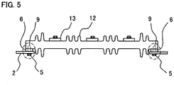
- FIG. 5 is a view illustrating an insulation degradation monitoring device according to Embodiment 3. Parts in FIG. 5 , which are equivalent to parts in FIG. 1 and FIG. 2 , are indicated by the same symbols, and explanations are omitted. Lead wires 7 and decision means 8, which are connected to electric current sensors 6, are omitted.
- An insulator 12 which is a monitored object according to Embodiment 3, supports, for example, a plurality of high-voltage charging portions 13, and the insulator 12 is supported by and fixed to grounding metal components 2 at a plurality of portions (two portions at both sides in FIG. 5 ).
- the insulator 12 As a specific example of an electric instrument in which the insulator 12 is used, for example, switchgear or the like, in which breakers and a bus line are arranged in a cabinet, is estimated, and the specific example is a case in which the three-phase high-voltage charging portions 13, which are connected to the three-phase breakers, are attached to the grounding metal components 2 at the cabinet side via the insulator 12.
- parts, which are surrounded by a dot-and-dash line in FIG. 5 are fixed by a similar way for the attachment portion according to Embodiment 1 in such way that the electric current sensors 6 are penetrated by protruding portions 9a (not illustrated) of buried metals 9 which are provided at a side of the insulator 12.
- the insulation degradation monitoring device is configured as described above, whereby a leakage electric current is passed through any of the left and right electric current sensors 6, or is passed through the both electric current sensors 6. Therefore, the leakage electric current, which is detected by a plurality of electric current sensors 6, is input to one decision means (not illustrated), and a value of the leakage electric current is integrated, whereby an electric current value of the leakage electric current, which is passed through one insulator 12, is obtained.
- Correlation data, which is previously obtained, between the leakage electric current and a degradation degree is memorized in the decision means 8, and the degradation degree of the insulator 12 is decided in the decision means 8 by, for example, the method which is explained in Embodiment 1.
- the insulator and the grounding metal component are connected at a plurality of portions and comprise a plurality of connecting portions, and the electric current sensors are provided at each of the plurality of connecting portions, and values of the leakage electric currents, which are detected at the plurality of connecting portions, are integrated at the decision means, and a degradation degree of the insulator is decided in accordance with the values of the leakage electric currents, which are integrated, so that the decision means is applied to the insulator, in which the connecting portions for the grounding metal component are provided at a plurality of potions, and an effect, which is similar to the effect according to Embodiment 1, can be obtained.
Landscapes
- Physics & Mathematics (AREA)
- General Physics & Mathematics (AREA)
- Chemical & Material Sciences (AREA)
- Engineering & Computer Science (AREA)
- Ceramic Engineering (AREA)
- Testing Of Short-Circuits, Discontinuities, Leakage, Or Incorrect Line Connections (AREA)
- Testing Relating To Insulation (AREA)
Abstract
Description
- The present invention relates to an insulation degradation monitoring device which monitors a degradation state of an insulator supporting a charging portion of an electric instrument such as a power switchboard or the like.
- In an inner portion of a heavy electric instrument such as a power switchboard, there exist bus lines as well as many high-voltage charging portions of a main circuit instrument and the bus line and the high-voltage charging portions are supported at a grounding portion side by an insulator. The insulator is used during a long period in a state where the high-voltage charging portions are supported by the insulator, whereby an insulation capability is deteriorated, and a leakage electric current, which is flowed from a charging portion side through the insulator to the grounding portion side, is increased.
- When an increment of the leakage electric current is left, the degradation of the insulator is more advanced, and the leakage electric current is a generation factor of a ground fault in a worst case. In order to previously prevent aground fault, it is required that a degradation state of the insulator is monitored, and the insulator is replaced at a suitable period. Suitable replacement timing is required for effective operation of an electric power receiving and transforming facility.
- As a conventional art for detecting a degradation degree of an insulator in an electric power receiving facility, for example, there is a known art by which dust in an electric power receiving panel is collected, and a surface resistivity of the insulator is calculated in accordance with a value of an ion, which is included in the dust, a temperature and a humidity history, and moreover, a remaining life of the insulator is estimated in accordance with a threshold value which is determined in accordance the surface resistivity of the insulator and a surface resistivity of a new insulator, a usage lapse age of the insulator, and an amount of the dust, whereby a suitable replacement timing is decided (for example, refer to Patent Document 1).
- Moreover, there is a known art by which an electric conductor is provided at an interphase portion of an insulation frame, in which a three-phase vacuum circuit breaker is installed, and the electric conductor is connected to a grounding metal, and a leakage electric current, which is passed through the outside or the inside of the insulation frame and is flowed to an interphase portion of a charging portion in accordance with an insulation degradation of the insulation frame, is led to an insulation metal via the electric conductor, and a ground-fault relay is operated and a leakage electric current of the relay is detected, whereby an insulation degradation degree is grasped (for example, refer to Patent Document 2).
-
Patent Document 1: Japanese Laid-Open Patent Publication JP 2014-023 401 A Page 3,FIG. 1 )Patent Document 2: Japanese Laid-Open Patent Publication JP 2003-083 831 A Page 3,FIG. 1 to FIG. 3 ) - In a method which is described in the Patent Document 1, an electric power failure of an electric power receiving and transforming facility is required in order to collect dust which adheres to a surface of an insulator, and periodic maintenance work such as cleaning of the insulator is required. All the aforementioned facts cause a disturbance of facility operations.
- In order to avoid the problem, there is a described technology in which a correlation between an amount of dust at a floor surface of a board and an amount of the dust at the surface of the insulator is grasped, and the amount of the dust at the surface of the insulator is estimated in accordance with the dust which is collected from the floor surface.
- However, even in this case, it is required that the dust is collected at every time when the dust is measured, and moreover, there has been a problem in that many work operations, in which a value of an ion, which is included in the dust, and data of a temperature and a humidity are obtained, are required.
- Moreover, although a degradation monitoring technology, which is described in the
Patent Document 2, is effective for an insulation monitoring of an insulation frame in which a three-phase vacuum circuit breaker is installed, it is difficult that an insulator, which is deteriorated, is identified in a configuration in which many insulators, which support a high-voltage charging portion, are arranged in, for example, a cabinet of a power switchboard which is grounded, and there has been a problem in that the degradation monitoring technology is applied to a general insulator which supports a charging portion. - The present invention has been made to solve the above-described problems, and the object of the invention is to obtain an insulation degradation monitoring device by means of which a degradation state of an insulator can be constantly monitored by a simple configuration even when a plurality of insulators, which support a high-voltage charging portion as a power switchboard, are included, and a degradation degree can be decided.
- An insulation degradation monitoring device of the present invention, for an insulator, by which a high-voltage charging portion of an electric instrument is insulated from and supported to a grounding metal component, comprises an electric current sensor which is inserted to a connecting portion of the insulator and the grounding metal component, and detects a leakage electric current which is passed from the high-voltage charging portion through the insulator and is flowed to the grounding metal component; and a decision means which is connected to an output side of the electric current sensor, and decides a degradation degree of the insulator in accordance with a value of the leakage electric current.
- According to an insulation degradation monitoring device of the present invention, the insulation degradation monitoring device comprises an electric current sensor which detects a leakage electric current which is passed from a high-voltage charging portion to an insulator and is flowed to a grounding metal component, and a decision means which decides a degradation degree of the insulator in accordance with a value of the detected leakage electric current, so that the leakage electric current, which is passed from the high-voltage charging portion through the insulator and is flowed to the grounding metal component, can be constantly monitored, and the degradation degree of the insulator can be decided in accordance with an increment of the leakage electric current, whereby timing for replacing the insulator can be estimated before a ground fault or the like is caused.
- Moreover, the insulation degradation monitoring device can be easily applied to each insulator in an electric instrument having a plurality of insulators, so that an insulator, which is deteriorated, is easily identified.
-
- FIG. 1
- is a front view illustrating an insulation degradation monitoring device according to Embodiment 1 of the present invention;
- FIG. 2
- is a disassembled oblique perspective view illustrating a detail of an attachment portion at a grounding side of the insulation degradation monitoring device in
FIG. 1 ; - FIG. 3
- is an explanatory view for explaining an example of a decision method for insulation degradation;
- FIG. 4
- is a partial cross-sectional view illustrating an electric current sensor of an insulation degradation monitoring device according to
Embodiment 2; and - FIG. 5
- is a front view illustrating an insulation degradation monitoring device according to
Embodiment 3. -
FIG. 1 is a front view illustrating an insulation degradation monitoring device according to Embodiment 1.FIG. 2 is a detailed view illustrating an attachment portion at a grounding side of the insulation degradation monitoring device inFIG. 1, and FIG. 2 is a disassembled oblique perspective view in which the insulation degradation monitoring device inFIG. 1 is viewed from a lower direction. -
FIG. 1 indicates an example of an insulator, as an insulator which is an object of a degradation monitoring, which supports a charging portion of an electric instrument of a power switchboard or the like, and a high-voltage charging portion 1 is a bus line or a main circuit conductor. Agrounding metal component 2 is a part of a cabinet of a power switchboard, or is a supporting metal component or the like, which is fixed to the cabinet, and thegrounding metal component 2 is grounded. Moreover, aninsulator 3 is, for example, a supporting insulator. The high-voltage charging portion 1 is supported by and fixed to thegrounding metal component 2 via theinsulator 3. - The high-voltage charging portion 1 is fixed to the
insulator 3 by using a chargingportion fixing bolt 4. Moreover, theinsulator 3 and thegrounding metal component 2 are fixed by using a groundingportion fixing bolt 5. - An
electric current sensor 6 is arranged at a connecting portion of theinsulator 3 and thegrounding metal component 2. Theelectric current sensor 6 is composed of a penetration-type electric current detector having an annular shape, and in particular, theelectric current sensor 6 is, for example, a small penetration-type CT, and detects a minute leakage electric current which is passed from the high-voltage charging portion 1 through theinsulator 3 and is flowed to thegrounding metal component 2. - An output side, which is a secondary side of the
electric current sensor 6, is connected to a decision means 8 via alead wire 7. The decision means 8 is provided in, for example, a control section of an electric instrument, in which the high-voltage charging portion 1 and theinsulator 3 are installed. - Hereinafter, a detailed configuration of an attachment portion, by which the
electric current sensor 6 is attached to thegrounding metal component 2, will be explained in reference toFIG. 2 . - A buried
metal 9, which is composed of a metal component having a cylindrical shape, is buried at an end portion of theinsulator 3 which is connected to thegrounding metal component 2. A female screw for attaching is processed at a center of the buriedmetal 9. Aprotruding portion 9a is formed at a facing side of the buriedmetal 9 toward thegrounding metal component 2, in a state where an end portion at an attachment side is protruding from an end surface of theinsulator 3. - It is desirable that a protrusion length of the protruding
portion 9a is slightly longer than a thickness of theelectric current sensor 6. An outer diameter of the protrudingportion 9a is smaller than a thickness of theelectric current sensor 6 having an annular shape, whereby it is possible that theelectric current sensor 6 is easily fitted to the protrudingportion 9a. - In addition, although it is general that a buried metal is provided at a connecting portion side of the
insulator 3 toward the high-voltage charging portion 1, the buried metal is not a main portion, so that an illustration and an example are omitted. - In an assembling process, firstly, a screw hole of the buried
metal 9 is fitted to amounting hole 2a of thegrounding metal component 2, and thegrounding metal component 2 is tightened and fixed by the groundingportion fixing bolt 5, in a state where theelectric current sensor 6 is fitted to the protrudingportion 9a of the buriedmetal 9 which is buried in theinsulator 3. - A protrusion length of the protruding
portion 9a is longer than a thickness of theelectric current sensor 6, whereby theinsulator 3 and thegrounding metal component 2 are fixed in a state where theinsulator 3 and thegrounding metal component 2 are certainly contacted at a tip of the protrudingportion 9a of the buriedmetal 9, and a load is not applied to theelectric current sensor 6 by tightening thegrounding metal component 2, and the protrudingportion 9a is used as a passage of a leakage electric current. - The
lead wire 7 of theelectric current sensor 6 is connected to the decision means 8. Thelead wire 7 is bundled to thegrounding metal component 2 or the like, and thelead wire 7 is wired in a state where an insulation distance is maintained with respect to a charging portion. A state, after the assembling process is performed, is indicated asFIG. 1 . - Hereinafter, an operation of the insulation degradation monitoring device will be explained.
- An insulation capability of the
insulator 3, which supports the high-voltage charging portion 1, is decreased in accordance with an aged deterioration which is caused by using theinsulator 3 for the long term. Thereby, a leakage electric current, which is flowed from the high-voltage charging portion 1 to a grounding side, is increased. - Therefore, the leakage electric current is constantly monitored by the electric
current sensor 6, and the degradation of theinsulator 3 is monitored by checking a variation of the leakage electric current. - The leakage electric current is passed through the
insulator 3 and is flowed from the high-voltage charging portion 1 to thegrounding metal component 2. Theinsulator 3 is fixed in a state where a tip of the protrudingportion 9a of the buriedmetal 9 and the groundingmetal component 2 are contacted, so that the leakage electric current, which is passed from theinsulator 3, is flowed to the groundingmetal component 2 via the protrudingportion 9a. - The electric
current sensor 6 is provided in a state where the electriccurrent sensor 6 is penetrated by the protrudingportion 9a, and a surface of the electriccurrent sensor 6 is insulated, so that a minute leakage electric current, which is flowed from theinsulator 3 to the groundingmetal component 2, is intensively flowed to the protrudingportion 9a of the buriedmetal 9 of which electric resistance is low, and the leakage electric current is passed through the inside of the electriccurrent sensor 6. Therefore, the minute leakage electric current can be easily detected, with high accuracy, by the electriccurrent sensor 6. - A value of the leakage electric current, which is detected by the electric
current sensor 6, is input to the decision means 8 via thelead wire 7. Correlation data, which is previously obtained, between the leakage electric current of theinsulator 3 and a degradation degree is memorized in the decision means 8. - In this case, the leakage electric current is compared with the correlation data, and when the value of the leakage electric current, which is detected by the electric
current sensor 6, exceeds a predetermined value, it is decided that the degradation of theinsulator 3 proceeds, and the leakage electric current is used for a guideline of cleaning or replacement of theinsulator 3. - An example of a decision method by the decision means 8 will be explained in reference to
FIG. 3. FIG. 3 is an explanatory view for explaining an example of a decision method for insulation degradation. - If the degradation of the
insulator 3 proceeds, an insulation resistance of theinsulator 3 is decreased. Therefore, an insulation resistance value is used as a parameter of a degradation degree. There is a correlation, which is indicated by a thick line inFIG. 3 , between the insulation resistance of theinsulator 3 and the leakage electric current. Correlation data, which is indicated inFIG. 3 , is previously obtained with respect to theinsulator 3 which is a monitored object. - Moreover, a value of a leakage electric current with respect to a required minimum value of an insulation resistance, which is required for maintaining an insulation capability, is determined as a reference value, and the values are memorized in a memory unit of the decision means 8.
- In addition, the reference value or the like is different in accordance with a shape, the quality of a material or the like of the
insulator 3, so that the correlation data is obtained for each of insulators of which kinds are different. Moreover, it is suitable that the required minimum value is determined in accordance with, for example, a replacement recommendable period or a cleaning recommendable period. - When the value of the leakage electric current, which is detected by the electric
current sensor 6, exceeds a reference value, it is decided that the degradation of theinsulator 3 proceeds more than predetermined degradation, and, for example, a replacement recommendable period of theinsulator 3 is reached, whereby the replacement of theinsulator 3 can be prepared. - Although it is general that many insulators, which support the high-voltage charging portion 1, are used at a plurality of positions in an inner portion of an electric instrument, a similar insulation degradation monitoring device is provided for an insulator to which a monitoring operation is required, whereby a deteriorated insulator can be easily identified. It is suitable that only a small electric current sensor is provided with respect to the
insulator 3, so that theinsulator 3 is simply disposed. - In the above-described explanation, although the
insulator 3 is explained as a supporting insulator, theinsulator 3 is not limited to the supporting insulator, and when theinsulator 3 is an insulator by which the high-voltage charging portion 1 is supported and fixed to the groundingmetal component 2, theinsulator 3 can be applied to a general insulation supporting component of an electric instrument. A material of theinsulator 3 is not particularly limited, and theinsulator 3 can be widely applied to an insulation material, which is generally known, such as a ceramic or an epoxy resin. - Moreover, although the electric
current sensor 6 is explained as a penetration-type CT, for example, a Rogowski coil may be used for the electriccurrent sensor 6 in the other case. - As described above, according to Embodiment 1, the insulation degradation monitoring device for an insulator, by which a high-voltage charging portion of an electric instrument is insulated from and supported to a grounding metal component, comprises an electric current sensor which is inserted to a connecting portion of the insulator and the grounding metal component, and detects a leakage electric current which is passed from the high-voltage charging portion through the insulator and is flowed to the grounding metal component, and a decision means which is connected to an output side of the electric current sensor, and decides a degradation degree of the insulator in accordance with a value of the leakage electric current, so that the leakage electric current, which is passed from the high-voltage charging portion through the insulator and is flowed to the grounding metal component, can be constantly monitored, and the degradation degree of the insulator can be decided in accordance with an increment of the leakage electric current. Therefore, the insulation degradation can be early discovered, and timing for replacing the insulator can be estimated before a ground fault or the like is caused.
- Moreover, even in an electric instrument which comprises a plurality of insulators, an electric current sensor can be easily disposed, and a deteriorated insulator can be easily identified.
- Moreover, the buried metal, which comprises a screw hole for attaching, is provided at an end portion of the insulator, which is connected to the grounding metal component, and a facing side of the buried metal toward the grounding metal component is formed as a protruding portion which is protruding from an end surface of the insulator, and the electric current sensor is composed of a penetration-type electric current detector, and the electric current sensor is penetrated by the protruding portion so as to be arranged between the insulator and the grounding metal component, whereby a leakage electric current is intensively flowed to the protruding portion of the buried metal, of which electric resistance is low, and is passed through the inside of the electric current sensor, so that detection accuracy of the leakage electric current is improved.
- Moreover, the electric current sensor can be easily attached to a connecting portion of the insulator and the grounding metal component, and the insulation degradation monitoring device, of which assembling workability is excellent, can be obtained.
-
FIG. 4 is a partial cross-sectional view illustrating an electric current sensor of an insulation degradation monitoring device, for an insulator, according toEmbodiment 2. A dot-and-dash line inFIG. 4 is an axis symmetric line, andFIG. 4 indicates only a left half portion of the electric current sensor. Parts inFIG. 4 , which are equivalent to parts inFIG. 1 and FIG. 2 according to Embodiment 1, are indicated by the same symbols, and detailed explanations are omitted, and difference points will be mainly explained. In addition, alead wire 7 and a decision means 8, which are connected to the electric current sensor, are omitted. - As illustrated in
FIG. 4 , a plurality ofpleats 10a is provided at an outer circumferential portion of an electriccurrent sensor 10 according toEmbodiment 2. As illustrated inFIG. 4 , the outside of a coil at a center portion is covered by an insulation component at a cross section of the electriccurrent sensor 10, so that thepleats 10a are provided at an outer circumference side of the insulation component. - Moreover, a
conductive sleeve 11, which is composed of a conductive component having a cylindrical shape, of which electric resistance is low, is inserted to a gap between an inner circumference side of the electriccurrent sensor 10 and an outer circumference side of a protrudingportion 9a. - In a size relation among a protrusion length of the protruding
portion 9a of the buriedmetal 9, a height of the electriccurrent sensor 10, and a length of theconductive sleeve 11, the length of theconductive sleeve 11 is the longest, and the protrusion length of the protrudingportion 9a and the height of the electriccurrent sensor 10 are shorter than the length of theconductive sleeve 11. - Thereby, in an attachment state which is indicated in
FIG. 4 , the electriccurrent sensor 10 is configured in such a way that one end portion of theconductive sleeve 11 is contacted to aninsulator 3, and the other end portion of theconductive sleeve 11 is contacted to agrounding metal component 2. - Hereinafter, an operation of the insulation degradation monitoring device will be explained.
- The
pleats 10a are provided at the outer circumferential portion of the electriccurrent sensor 10, whereby a creepage distance of the outer circumferential portion is longer than a creepage distance of the inner circumferential portion. Therefore, if theinsulator 3 and the electriccurrent sensor 10 are contacted, a leakage electric current is mainly passed through the inner circumferential portion of the electriccurrent sensor 10. - Moreover, the
conductive sleeve 11 is provided at the inside of the electriccurrent sensor 10, and theinsulator 3 and theconductive sleeve 11, and theconductive sleeve 11 and the groundingmetal component 2 are certainly contacted, whereby a leakage electric current is passed through theconductive sleeve 11, of which electric resistance is low, and is flowed to the groundingmetal component 2. Thereby, the leakage electric current is more certainly passed through the inside of the electriccurrent sensor 10, and a minute leakage electric current, which is flowed to theinsulator 3, can be detected with high accuracy by the electriccurrent sensor 10, so that an insulation degradation state of theinsulator 3 can be certainly decided. - Moreover, the protruding
portion 9a is contacted to the groundingmetal component 2 via theconductive sleeve 11, so that when a protrusion length of the protrudingportion 9a is shorter than a length of theconductive sleeve 11, it is not particularly required that a size is controlled, and the insulation degradation monitoring device is simply made. - Moreover, even when an existing insulator does not comprise a protruding portion at a buried metal, it is possible that the
conductive sleeve 11 is inserted at a later timing, and the electric current sensor is attached. - In addition, in
FIG. 4 , although the insulation degradation monitoring device has a configuration in which thepleats 10a are provided at an outer circumferential portion of an electriccurrent sensor 10, and theconductive sleeve 11 is included, it is suitable that the insulation degradation monitoring device has a configuration in which theconductive sleeve 11 is not included and only thepleats 10a are provided, or has a configuration in which thepleats 10a are not provided and only theconductive sleeve 11 is included. In this case, each of effects can be respectively obtained. - As described above, in the insulation degradation monitoring device according to
Embodiment 2, a plurality of pleats are provided at an outer circumferential portion of the electric current sensor, so that a leakage electric current is mainly passed through an inner circumference side of the electric current sensor, whereby detection accuracy of the leakage electric current, which is detected by the electric current sensor, is improved. - Moreover, the insulation degradation monitoring device is configured in such a way that the conductive sleeve having a cylindrical shape is inserted to an inner circumference side of the electric current sensor, and one end portion of the conductive sleeve is contacted to the insulator, and the other end portion of the conductive sleeve is contacted to the grounding metal component, so that the leakage electric current is passed through the conductive sleeve, of which electric resistance is low, and is flowed to the grounding metal component, whereby the leakage electric current is certainly passed through the inside of the electric current sensor, and the leakage electric current, which is flowed to the insulator, can be detected with high accuracy, and an insulation degradation state of the insulator can be decided with high accuracy.
-
FIG. 5 is a view illustrating an insulation degradation monitoring device according toEmbodiment 3. Parts inFIG. 5 , which are equivalent to parts inFIG. 1 and FIG. 2 , are indicated by the same symbols, and explanations are omitted.Lead wires 7 and decision means 8, which are connected to electriccurrent sensors 6, are omitted. - An
insulator 12, which is a monitored object according toEmbodiment 3, supports, for example, a plurality of high-voltage charging portions 13, and theinsulator 12 is supported by and fixed to groundingmetal components 2 at a plurality of portions (two portions at both sides inFIG. 5 ). - As a specific example of an electric instrument in which the
insulator 12 is used, for example, switchgear or the like, in which breakers and a bus line are arranged in a cabinet, is estimated, and the specific example is a case in which the three-phase high-voltage charging portions 13, which are connected to the three-phase breakers, are attached to the groundingmetal components 2 at the cabinet side via theinsulator 12. - As illustrated in
FIG. 5 , the high-voltage charging portions 13, which are, for example, three-phase main circuit conductors, are supported by and fixed to oneinsulator 12, and two portions at both sides of theinsulator 12 are attached to the groundingmetal components 2. In this case, parts, which are surrounded by a dot-and-dash line inFIG. 5 , are fixed by a similar way for the attachment portion according to Embodiment 1 in such way that the electriccurrent sensors 6 are penetrated by protrudingportions 9a (not illustrated) of buriedmetals 9 which are provided at a side of theinsulator 12. - In addition, it is suitable that the configuration of the attachment portion in
FIG. 4 according toEmbodiment 2 is adopted for a configuration of an attachment portion according toEmbodiment 3. - The insulation degradation monitoring device is configured as described above, whereby a leakage electric current is passed through any of the left and right electric
current sensors 6, or is passed through the both electriccurrent sensors 6. Therefore, the leakage electric current, which is detected by a plurality of electriccurrent sensors 6, is input to one decision means (not illustrated), and a value of the leakage electric current is integrated, whereby an electric current value of the leakage electric current, which is passed through oneinsulator 12, is obtained. - Correlation data, which is previously obtained, between the leakage electric current and a degradation degree is memorized in the decision means 8, and the degradation degree of the
insulator 12 is decided in the decision means 8 by, for example, the method which is explained in Embodiment 1. - As described above, in the insulation degradation monitoring device according to
Embodiment 3, the insulator and the grounding metal component are connected at a plurality of portions and comprise a plurality of connecting portions, and the electric current sensors are provided at each of the plurality of connecting portions, and values of the leakage electric currents, which are detected at the plurality of connecting portions, are integrated at the decision means, and a degradation degree of the insulator is decided in accordance with the values of the leakage electric currents, which are integrated, so that the decision means is applied to the insulator, in which the connecting portions for the grounding metal component are provided at a plurality of potions, and an effect, which is similar to the effect according to Embodiment 1, can be obtained. - In addition, in the scope of the present invention, it is possible that each of embodiments is freely combined, or each of embodiments is suitably modified or omitted.
-
- 1
- is a high-voltage charging portion
- 2
- a grounding metal component
- 2a
- a mounting hole
- 3
- an insulator
- 4
- a charging portion fixing bolt
- 5
- a grounding portion fixing bolt
- 6
- an electric current sensor
- 7
- a lead wire
- 8
- a decision means
- 9
- a buried metal
- 9a
- a protruded portion;
- 10 an
- electric current sensor
- 10a
- pleats
- 11
- a conductive sleeve
- 12
- an insulator
- 13
- high-voltage charging portions
Claims (5)
- An insulation degradation monitoring device for an insulator, by which a high-voltage charging portion of an electric instrument is insulated from and supported to a grounding metal component, comprising:- an electric current sensor which is inserted to a connecting portion of the insulator and the grounding metal component, and detects a leakage electric current which is passed from the high-voltage charging portion through the insulator and is flowed to the grounding metal component; and- a decision means which is connected to an output side of the electric current sensor, and decides a degradation degree of the insulator in accordance with a value of the leakage electric current.
- The insulation degradation monitoring device according to claim 1,
wherein a buried metal, which comprises a screw hole for attaching, is provided at an end portion of the insulator which is connected to the grounding metal component, and a facing side of the buried metal toward the grounding metal component is formed as a protruding portion which is protruding from an end surface of the insulator, and the electric current sensor is composed of a penetration-type electric current detector, and the electric current sensor is penetrated by the protruding portion so as to be arranged between the insulator and the grounding metal component. - The insulation degradation monitoring device according to claim 2,
wherein a plurality of pleats are provided at an outer circumferential portion of the electric current sensor. - The insulation degradation monitoring device according to claim 2 or 3,
wherein a conductive sleeve having a cylindrical shape is inserted to an inner circumference side of the electric current sensor, and one end portion of the conductive sleeve is contacted to the insulator, and the other end portion of the conductive sleeve is contacted to the grounding metal component. - The insulation degradation monitoring device
according to any one of claims 1 to 4,
wherein the insulator and the grounding metal component comprise a plurality of connecting portions which are connected each other, and the electric current sensor is provided at each of the plurality of connecting portions, and a value of the leakage electric current, which is detected at the plurality of connecting portions, is integrated at the decision means, and a degradation degree of the insulator is decided in accordance with the value of the integrated leakage electric current.
Applications Claiming Priority (2)
| Application Number | Priority Date | Filing Date | Title |
|---|---|---|---|
| JP2014197915 | 2014-09-29 | ||
| PCT/JP2015/077029 WO2016052314A1 (en) | 2014-09-29 | 2015-09-25 | Insulation deterioration monitor device |
Publications (3)
| Publication Number | Publication Date |
|---|---|
| EP3203249A1 true EP3203249A1 (en) | 2017-08-09 |
| EP3203249A4 EP3203249A4 (en) | 2018-05-30 |
| EP3203249B1 EP3203249B1 (en) | 2022-01-12 |
Family
ID=55630352
Family Applications (1)
| Application Number | Title | Priority Date | Filing Date |
|---|---|---|---|
| EP15847716.6A Active EP3203249B1 (en) | 2014-09-29 | 2015-09-25 | Insulation deterioration monitor device |
Country Status (6)
| Country | Link |
|---|---|
| US (1) | US10161987B2 (en) |
| EP (1) | EP3203249B1 (en) |
| JP (1) | JP6033499B2 (en) |
| KR (1) | KR101902716B1 (en) |
| CN (1) | CN107076796B (en) |
| WO (1) | WO2016052314A1 (en) |
Families Citing this family (8)
| Publication number | Priority date | Publication date | Assignee | Title |
|---|---|---|---|---|
| FR3057697B1 (en) * | 2016-10-18 | 2020-02-14 | Sediver Sa | ISOLATOR FOR OVERHEAD POWER LINES WITH A PROTECTED LEAKAGE CURRENT |
| US11443155B2 (en) * | 2018-01-19 | 2022-09-13 | Lindsey Manufacturing Company | Insulator leakage current detector and method of detecting insulator leakage current |
| KR102029745B1 (en) * | 2018-06-07 | 2019-10-08 | 가보 주식회사 | System and method for insulation deterioration monitoring analysis of transformer bushing with bushing tap |
| EP3667338B1 (en) * | 2018-12-11 | 2021-08-18 | ABB Schweiz AG | Switchgear leakage current monitoring system for a high voltage or medium voltage switchgear |
| CN110133454A (en) * | 2019-04-17 | 2019-08-16 | 南京合继思瑞电力科技有限公司 | A kind of electric insulation part leakage current monitoring device |
| CN111880066B (en) * | 2020-07-27 | 2025-06-20 | 国网河南省电力公司电力科学研究院 | Test sample preparation method and sample preparation auxiliary device for rod-shaped composite insulator |
| CN112636228A (en) * | 2020-12-09 | 2021-04-09 | 广东欣粤电力器材有限公司 | Full-insulation power transformation rack |
| CN119147885B (en) * | 2024-11-19 | 2025-04-15 | 华南理工大学 | Life prediction method for composite insulator core rod under electric-thermal-mechanical multi-field aging |
Family Cites Families (23)
| Publication number | Priority date | Publication date | Assignee | Title |
|---|---|---|---|---|
| JPS62207974A (en) * | 1986-03-07 | 1987-09-12 | Ngk Insulators Ltd | Monitoring system for lightning insulator |
| JPH0348778A (en) * | 1989-07-17 | 1991-03-01 | Mitsubishi Electric Corp | Leakage current detecting device |
| JPH074587Y2 (en) * | 1990-04-03 | 1995-02-01 | 東洋通信機株式会社 | Current sensor bobbin structure |
| JPH04262265A (en) * | 1991-01-10 | 1992-09-17 | Mitsubishi Electric Corp | current sensor |
| JP2932771B2 (en) * | 1991-07-30 | 1999-08-09 | 松下電器産業株式会社 | Distribution line monitoring device |
| JP3759219B2 (en) * | 1996-02-07 | 2006-03-22 | 東北特殊鋼株式会社 | insulator |
| SE508154C2 (en) * | 1996-10-16 | 1998-09-07 | Abb Research Ltd | Device for monitoring partial discharges in an electric high-voltage apparatus or high-voltage equipment |
| JP3757508B2 (en) * | 1996-12-26 | 2006-03-22 | 日新電機株式会社 | Eggplant contamination monitoring device |
| JP3413045B2 (en) * | 1997-02-21 | 2003-06-03 | 株式会社東芝 | Support insulator |
| JPH11304871A (en) * | 1998-04-16 | 1999-11-05 | Nissin Electric Co Ltd | Insulator contamination detecting apparatus |
| DE10125910B4 (en) * | 2000-05-30 | 2007-02-01 | International Rectifier Corp., El Segundo | Method and circuit for detecting motor insulation faults |
| JP2003083831A (en) | 2001-09-13 | 2003-03-19 | Fuji Electric Co Ltd | Vacuum circuit breaker |
| JP2006266709A (en) * | 2005-03-22 | 2006-10-05 | Shikoku Electric Power Co Inc | Insulator leakage current measurement apparatus |
| CN201130598Y (en) * | 2007-12-10 | 2008-10-08 | 河南森源电气股份有限公司 | Low voltage coil locating structure of current transformer |
| US8461824B2 (en) * | 2010-06-07 | 2013-06-11 | Infineon Technologies Ag | Current sensor |
| JP5247874B2 (en) * | 2011-12-06 | 2013-07-24 | パナソニック株式会社 | Storage battery transfer support device and storage battery transfer support method |
| US9903899B2 (en) * | 2011-12-28 | 2018-02-27 | Electric Power Research Institute, Inc. | Leakage current sensor for post type insulator |
| WO2013160991A1 (en) * | 2012-04-23 | 2013-10-31 | 中国電力株式会社 | Scintillation estimation method |
| JP5944773B2 (en) | 2012-07-24 | 2016-07-05 | 株式会社日立製作所 | Method for diagnosing remaining life of insulators in substation equipment |
| NO341197B1 (en) * | 2012-10-24 | 2017-09-11 | Wirescan As | Method and system for monitoring the condition of electric cables |
| EP4109095A1 (en) * | 2014-09-09 | 2022-12-28 | Perosphere Technologies Inc. | Microfluid chip-based, universal coagulation assay |
| US20160131692A1 (en) * | 2014-11-12 | 2016-05-12 | Cameron International Corporation | Cable Monitoring Apparatus |
| CN107171030B (en) * | 2016-03-08 | 2022-02-11 | 松下知识产权经营株式会社 | Power storage system and control method of power storage system |
-
2015
- 2015-09-25 KR KR1020177006623A patent/KR101902716B1/en active Active
- 2015-09-25 WO PCT/JP2015/077029 patent/WO2016052314A1/en not_active Ceased
- 2015-09-25 EP EP15847716.6A patent/EP3203249B1/en active Active
- 2015-09-25 JP JP2016512153A patent/JP6033499B2/en active Active
- 2015-09-25 CN CN201580052141.0A patent/CN107076796B/en not_active Expired - Fee Related
- 2015-09-25 US US15/323,859 patent/US10161987B2/en active Active
Also Published As
| Publication number | Publication date |
|---|---|
| US10161987B2 (en) | 2018-12-25 |
| US20170146588A1 (en) | 2017-05-25 |
| JP6033499B2 (en) | 2016-11-30 |
| EP3203249B1 (en) | 2022-01-12 |
| CN107076796A (en) | 2017-08-18 |
| WO2016052314A1 (en) | 2016-04-07 |
| KR20170041858A (en) | 2017-04-17 |
| EP3203249A4 (en) | 2018-05-30 |
| KR101902716B1 (en) | 2018-09-28 |
| JPWO2016052314A1 (en) | 2017-04-27 |
| CN107076796B (en) | 2020-06-05 |
Similar Documents
| Publication | Publication Date | Title |
|---|---|---|
| EP3203249B1 (en) | Insulation deterioration monitor device | |
| JP5135129B2 (en) | Gas insulation equipment | |
| CN109313219B (en) | High voltage introduction insulation device | |
| US20080174320A1 (en) | Partial discharge sensor and partial discharge monitoring system utilizing current sensors | |
| KR20140005279A (en) | Method for identifying arcing faults and circuit breaker | |
| KR101916408B1 (en) | power distributing board monitoring apparatus | |
| CN110426616B (en) | A GIS partial discharge detection device and method based on flange bolts | |
| US5124687A (en) | Power apparatus, power transmission/distribution unit, and tripping method therefor | |
| US9455564B2 (en) | Current and voltage module and methods of monitoring current and voltage in power distribution systems | |
| KR101189520B1 (en) | Wall-trough bushing included voltage detctor | |
| JP2011252780A (en) | Detection method of partial discharge of electrical device using magnetic field probe | |
| EP3816641B1 (en) | Electrical device partial discharge monitoring | |
| US20220317159A1 (en) | Measuring an electrical voltage on a metal-encapsulated switchgear | |
| KR101325998B1 (en) | Insulated housing with voltage detection and power switching apparatus using that | |
| Sedding et al. | Progress in interpreting on-line partial discharge test results from motor and generator stator windings | |
| Birtwhistle et al. | A new technique for condition monitoring of MV metalclad switchgear | |
| JP3112034B2 (en) | Preventive maintenance system for substation equipment | |
| KR101325996B1 (en) | Insulated housing with voltage detection and power switching apparatus using that | |
| KR102772610B1 (en) | Apparatus for diagnosing partial discharge of power cable with N-type connector attatched terminal | |
| JP2006001394A (en) | Feeding cable monitoring device | |
| KR102953208B1 (en) | Apparatus for diagnosing partial discharge of power cable wherein male connector is installed therein | |
| KR102954764B1 (en) | Apparatus for diagnosing partial discharge of power cable wherein female connector is installed therein | |
| JPH07245853A (en) | Gas insulated electrical equipment | |
| EP4345433A1 (en) | Switchgear device | |
| Yusifov | RESEARCH OF PROBLEMS IN HIGH VOLTAGE MOTOR STATORS BY RADIO FREQUENCY CURRENT TRANSFORMERS |
Legal Events
| Date | Code | Title | Description |
|---|---|---|---|
| STAA | Information on the status of an ep patent application or granted ep patent |
Free format text: STATUS: THE INTERNATIONAL PUBLICATION HAS BEEN MADE |
|
| PUAI | Public reference made under article 153(3) epc to a published international application that has entered the european phase |
Free format text: ORIGINAL CODE: 0009012 |
|
| STAA | Information on the status of an ep patent application or granted ep patent |
Free format text: STATUS: REQUEST FOR EXAMINATION WAS MADE |
|
| 17P | Request for examination filed |
Effective date: 20170221 |
|
| AK | Designated contracting states |
Kind code of ref document: A1 Designated state(s): AL AT BE BG CH CY CZ DE DK EE ES FI FR GB GR HR HU IE IS IT LI LT LU LV MC MK MT NL NO PL PT RO RS SE SI SK SM TR |
|
| AX | Request for extension of the european patent |
Extension state: BA ME |
|
| DAV | Request for validation of the european patent (deleted) | ||
| DAX | Request for extension of the european patent (deleted) | ||
| A4 | Supplementary search report drawn up and despatched |
Effective date: 20180503 |
|
| RIC1 | Information provided on ipc code assigned before grant |
Ipc: G01R 19/165 20060101ALN20180424BHEP Ipc: G01R 31/02 20060101ALI20180424BHEP Ipc: G01R 31/12 20060101AFI20180424BHEP |
|
| REG | Reference to a national code |
Ref country code: DE Ref legal event code: R079 Ref document number: 602015076469 Country of ref document: DE Free format text: PREVIOUS MAIN CLASS: G01R0031120000 Ipc: G01R0031520000 |
|
| GRAP | Despatch of communication of intention to grant a patent |
Free format text: ORIGINAL CODE: EPIDOSNIGR1 |
|
| STAA | Information on the status of an ep patent application or granted ep patent |
Free format text: STATUS: GRANT OF PATENT IS INTENDED |
|
| RIC1 | Information provided on ipc code assigned before grant |
Ipc: G01R 31/52 20200101AFI20210705BHEP Ipc: G01R 31/12 20200101ALI20210705BHEP Ipc: G01R 19/165 20060101ALN20210705BHEP |
|
| RIC1 | Information provided on ipc code assigned before grant |
Ipc: G01R 31/52 20200101AFI20210712BHEP Ipc: G01R 31/12 20200101ALI20210712BHEP Ipc: G01R 19/165 20060101ALN20210712BHEP |
|
| INTG | Intention to grant announced |
Effective date: 20210806 |
|
| GRAS | Grant fee paid |
Free format text: ORIGINAL CODE: EPIDOSNIGR3 |
|
| GRAA | (expected) grant |
Free format text: ORIGINAL CODE: 0009210 |
|
| STAA | Information on the status of an ep patent application or granted ep patent |
Free format text: STATUS: THE PATENT HAS BEEN GRANTED |
|
| AK | Designated contracting states |
Kind code of ref document: B1 Designated state(s): AL AT BE BG CH CY CZ DE DK EE ES FI FR GB GR HR HU IE IS IT LI LT LU LV MC MK MT NL NO PL PT RO RS SE SI SK SM TR |
|
| REG | Reference to a national code |
Ref country code: GB Ref legal event code: FG4D |
|
| REG | Reference to a national code |
Ref country code: CH Ref legal event code: EP |
|
| REG | Reference to a national code |
Ref country code: DE Ref legal event code: R096 Ref document number: 602015076469 Country of ref document: DE |
|
| REG | Reference to a national code |
Ref country code: IE Ref legal event code: FG4D |
|
| REG | Reference to a national code |
Ref country code: AT Ref legal event code: REF Ref document number: 1462733 Country of ref document: AT Kind code of ref document: T Effective date: 20220215 |
|
| REG | Reference to a national code |
Ref country code: LT Ref legal event code: MG9D |
|
| REG | Reference to a national code |
Ref country code: NL Ref legal event code: MP Effective date: 20220112 |
|
| REG | Reference to a national code |
Ref country code: AT Ref legal event code: MK05 Ref document number: 1462733 Country of ref document: AT Kind code of ref document: T Effective date: 20220112 |
|
| PG25 | Lapsed in a contracting state [announced via postgrant information from national office to epo] |
Ref country code: NL Free format text: LAPSE BECAUSE OF FAILURE TO SUBMIT A TRANSLATION OF THE DESCRIPTION OR TO PAY THE FEE WITHIN THE PRESCRIBED TIME-LIMIT Effective date: 20220112 |
|
| PG25 | Lapsed in a contracting state [announced via postgrant information from national office to epo] |
Ref country code: SE Free format text: LAPSE BECAUSE OF FAILURE TO SUBMIT A TRANSLATION OF THE DESCRIPTION OR TO PAY THE FEE WITHIN THE PRESCRIBED TIME-LIMIT Effective date: 20220112 Ref country code: RS Free format text: LAPSE BECAUSE OF FAILURE TO SUBMIT A TRANSLATION OF THE DESCRIPTION OR TO PAY THE FEE WITHIN THE PRESCRIBED TIME-LIMIT Effective date: 20220112 Ref country code: PT Free format text: LAPSE BECAUSE OF FAILURE TO SUBMIT A TRANSLATION OF THE DESCRIPTION OR TO PAY THE FEE WITHIN THE PRESCRIBED TIME-LIMIT Effective date: 20220512 Ref country code: NO Free format text: LAPSE BECAUSE OF FAILURE TO SUBMIT A TRANSLATION OF THE DESCRIPTION OR TO PAY THE FEE WITHIN THE PRESCRIBED TIME-LIMIT Effective date: 20220412 Ref country code: LT Free format text: LAPSE BECAUSE OF FAILURE TO SUBMIT A TRANSLATION OF THE DESCRIPTION OR TO PAY THE FEE WITHIN THE PRESCRIBED TIME-LIMIT Effective date: 20220112 Ref country code: HR Free format text: LAPSE BECAUSE OF FAILURE TO SUBMIT A TRANSLATION OF THE DESCRIPTION OR TO PAY THE FEE WITHIN THE PRESCRIBED TIME-LIMIT Effective date: 20220112 Ref country code: ES Free format text: LAPSE BECAUSE OF FAILURE TO SUBMIT A TRANSLATION OF THE DESCRIPTION OR TO PAY THE FEE WITHIN THE PRESCRIBED TIME-LIMIT Effective date: 20220112 Ref country code: BG Free format text: LAPSE BECAUSE OF FAILURE TO SUBMIT A TRANSLATION OF THE DESCRIPTION OR TO PAY THE FEE WITHIN THE PRESCRIBED TIME-LIMIT Effective date: 20220412 |
|
| PG25 | Lapsed in a contracting state [announced via postgrant information from national office to epo] |
Ref country code: PL Free format text: LAPSE BECAUSE OF FAILURE TO SUBMIT A TRANSLATION OF THE DESCRIPTION OR TO PAY THE FEE WITHIN THE PRESCRIBED TIME-LIMIT Effective date: 20220112 Ref country code: LV Free format text: LAPSE BECAUSE OF FAILURE TO SUBMIT A TRANSLATION OF THE DESCRIPTION OR TO PAY THE FEE WITHIN THE PRESCRIBED TIME-LIMIT Effective date: 20220112 Ref country code: GR Free format text: LAPSE BECAUSE OF FAILURE TO SUBMIT A TRANSLATION OF THE DESCRIPTION OR TO PAY THE FEE WITHIN THE PRESCRIBED TIME-LIMIT Effective date: 20220413 Ref country code: FI Free format text: LAPSE BECAUSE OF FAILURE TO SUBMIT A TRANSLATION OF THE DESCRIPTION OR TO PAY THE FEE WITHIN THE PRESCRIBED TIME-LIMIT Effective date: 20220112 Ref country code: AT Free format text: LAPSE BECAUSE OF FAILURE TO SUBMIT A TRANSLATION OF THE DESCRIPTION OR TO PAY THE FEE WITHIN THE PRESCRIBED TIME-LIMIT Effective date: 20220112 |
|
| PG25 | Lapsed in a contracting state [announced via postgrant information from national office to epo] |
Ref country code: IS Free format text: LAPSE BECAUSE OF FAILURE TO SUBMIT A TRANSLATION OF THE DESCRIPTION OR TO PAY THE FEE WITHIN THE PRESCRIBED TIME-LIMIT Effective date: 20220512 |
|
| REG | Reference to a national code |
Ref country code: DE Ref legal event code: R097 Ref document number: 602015076469 Country of ref document: DE |
|
| PG25 | Lapsed in a contracting state [announced via postgrant information from national office to epo] |
Ref country code: SM Free format text: LAPSE BECAUSE OF FAILURE TO SUBMIT A TRANSLATION OF THE DESCRIPTION OR TO PAY THE FEE WITHIN THE PRESCRIBED TIME-LIMIT Effective date: 20220112 Ref country code: SK Free format text: LAPSE BECAUSE OF FAILURE TO SUBMIT A TRANSLATION OF THE DESCRIPTION OR TO PAY THE FEE WITHIN THE PRESCRIBED TIME-LIMIT Effective date: 20220112 Ref country code: RO Free format text: LAPSE BECAUSE OF FAILURE TO SUBMIT A TRANSLATION OF THE DESCRIPTION OR TO PAY THE FEE WITHIN THE PRESCRIBED TIME-LIMIT Effective date: 20220112 Ref country code: EE Free format text: LAPSE BECAUSE OF FAILURE TO SUBMIT A TRANSLATION OF THE DESCRIPTION OR TO PAY THE FEE WITHIN THE PRESCRIBED TIME-LIMIT Effective date: 20220112 Ref country code: DK Free format text: LAPSE BECAUSE OF FAILURE TO SUBMIT A TRANSLATION OF THE DESCRIPTION OR TO PAY THE FEE WITHIN THE PRESCRIBED TIME-LIMIT Effective date: 20220112 Ref country code: CZ Free format text: LAPSE BECAUSE OF FAILURE TO SUBMIT A TRANSLATION OF THE DESCRIPTION OR TO PAY THE FEE WITHIN THE PRESCRIBED TIME-LIMIT Effective date: 20220112 |
|
| PLBE | No opposition filed within time limit |
Free format text: ORIGINAL CODE: 0009261 |
|
| STAA | Information on the status of an ep patent application or granted ep patent |
Free format text: STATUS: NO OPPOSITION FILED WITHIN TIME LIMIT |
|
| PG25 | Lapsed in a contracting state [announced via postgrant information from national office to epo] |
Ref country code: AL Free format text: LAPSE BECAUSE OF FAILURE TO SUBMIT A TRANSLATION OF THE DESCRIPTION OR TO PAY THE FEE WITHIN THE PRESCRIBED TIME-LIMIT Effective date: 20220112 |
|
| 26N | No opposition filed |
Effective date: 20221013 |
|
| PG25 | Lapsed in a contracting state [announced via postgrant information from national office to epo] |
Ref country code: SI Free format text: LAPSE BECAUSE OF FAILURE TO SUBMIT A TRANSLATION OF THE DESCRIPTION OR TO PAY THE FEE WITHIN THE PRESCRIBED TIME-LIMIT Effective date: 20220112 |
|
| PG25 | Lapsed in a contracting state [announced via postgrant information from national office to epo] |
Ref country code: MC Free format text: LAPSE BECAUSE OF FAILURE TO SUBMIT A TRANSLATION OF THE DESCRIPTION OR TO PAY THE FEE WITHIN THE PRESCRIBED TIME-LIMIT Effective date: 20220112 |
|
| REG | Reference to a national code |
Ref country code: CH Ref legal event code: PL |
|
| GBPC | Gb: european patent ceased through non-payment of renewal fee |
Effective date: 20220925 |
|
| REG | Reference to a national code |
Ref country code: BE Ref legal event code: MM Effective date: 20220930 |
|
| P01 | Opt-out of the competence of the unified patent court (upc) registered |
Effective date: 20230512 |
|
| PG25 | Lapsed in a contracting state [announced via postgrant information from national office to epo] |
Ref country code: LU Free format text: LAPSE BECAUSE OF NON-PAYMENT OF DUE FEES Effective date: 20220925 |
|
| PG25 | Lapsed in a contracting state [announced via postgrant information from national office to epo] |
Ref country code: LI Free format text: LAPSE BECAUSE OF NON-PAYMENT OF DUE FEES Effective date: 20220930 Ref country code: IT Free format text: LAPSE BECAUSE OF FAILURE TO SUBMIT A TRANSLATION OF THE DESCRIPTION OR TO PAY THE FEE WITHIN THE PRESCRIBED TIME-LIMIT Effective date: 20220112 Ref country code: IE Free format text: LAPSE BECAUSE OF NON-PAYMENT OF DUE FEES Effective date: 20220925 Ref country code: FR Free format text: LAPSE BECAUSE OF NON-PAYMENT OF DUE FEES Effective date: 20220930 Ref country code: CH Free format text: LAPSE BECAUSE OF NON-PAYMENT OF DUE FEES Effective date: 20220930 |
|
| PG25 | Lapsed in a contracting state [announced via postgrant information from national office to epo] |
Ref country code: BE Free format text: LAPSE BECAUSE OF NON-PAYMENT OF DUE FEES Effective date: 20220930 |
|
| PG25 | Lapsed in a contracting state [announced via postgrant information from national office to epo] |
Ref country code: GB Free format text: LAPSE BECAUSE OF NON-PAYMENT OF DUE FEES Effective date: 20220925 |
|
| PG25 | Lapsed in a contracting state [announced via postgrant information from national office to epo] |
Ref country code: HU Free format text: LAPSE BECAUSE OF FAILURE TO SUBMIT A TRANSLATION OF THE DESCRIPTION OR TO PAY THE FEE WITHIN THE PRESCRIBED TIME-LIMIT; INVALID AB INITIO Effective date: 20150925 |
|
| PG25 | Lapsed in a contracting state [announced via postgrant information from national office to epo] |
Ref country code: CY Free format text: LAPSE BECAUSE OF FAILURE TO SUBMIT A TRANSLATION OF THE DESCRIPTION OR TO PAY THE FEE WITHIN THE PRESCRIBED TIME-LIMIT Effective date: 20220112 |
|
| PG25 | Lapsed in a contracting state [announced via postgrant information from national office to epo] |
Ref country code: MK Free format text: LAPSE BECAUSE OF FAILURE TO SUBMIT A TRANSLATION OF THE DESCRIPTION OR TO PAY THE FEE WITHIN THE PRESCRIBED TIME-LIMIT Effective date: 20220112 |
|
| PG25 | Lapsed in a contracting state [announced via postgrant information from national office to epo] |
Ref country code: MT Free format text: LAPSE BECAUSE OF FAILURE TO SUBMIT A TRANSLATION OF THE DESCRIPTION OR TO PAY THE FEE WITHIN THE PRESCRIBED TIME-LIMIT Effective date: 20220112 |
|
| REG | Reference to a national code |
Ref country code: DE Ref legal event code: R084 Ref document number: 602015076469 Country of ref document: DE |
|
| PGFP | Annual fee paid to national office [announced via postgrant information from national office to epo] |
Ref country code: DE Payment date: 20250730 Year of fee payment: 11 |
|
| PG25 | Lapsed in a contracting state [announced via postgrant information from national office to epo] |
Ref country code: TR Free format text: LAPSE BECAUSE OF FAILURE TO SUBMIT A TRANSLATION OF THE DESCRIPTION OR TO PAY THE FEE WITHIN THE PRESCRIBED TIME-LIMIT Effective date: 20220112 |