EP3203248A1 - Method of locating a fault in a power transmission scheme - Google Patents
Method of locating a fault in a power transmission scheme Download PDFInfo
- Publication number
- EP3203248A1 EP3203248A1 EP16275017.8A EP16275017A EP3203248A1 EP 3203248 A1 EP3203248 A1 EP 3203248A1 EP 16275017 A EP16275017 A EP 16275017A EP 3203248 A1 EP3203248 A1 EP 3203248A1
- Authority
- EP
- European Patent Office
- Prior art keywords
- voltage
- power transmission
- phasors
- connection point
- phasor
- Prior art date
- Legal status (The legal status is an assumption and is not a legal conclusion. Google has not performed a legal analysis and makes no representation as to the accuracy of the status listed.)
- Granted
Links
Images


Classifications
-
- G—PHYSICS
- G01—MEASURING; TESTING
- G01R—MEASURING ELECTRIC VARIABLES; MEASURING MAGNETIC VARIABLES
- G01R31/00—Arrangements for testing electric properties; Arrangements for locating electric faults; Arrangements for electrical testing characterised by what is being tested not provided for elsewhere
- G01R31/08—Locating faults in cables, transmission lines, or networks
- G01R31/081—Locating faults in cables, transmission lines, or networks according to type of conductors
- G01R31/086—Locating faults in cables, transmission lines, or networks according to type of conductors in power transmission or distribution networks, i.e. with interconnected conductors
-
- G—PHYSICS
- G01—MEASURING; TESTING
- G01R—MEASURING ELECTRIC VARIABLES; MEASURING MAGNETIC VARIABLES
- G01R31/00—Arrangements for testing electric properties; Arrangements for locating electric faults; Arrangements for electrical testing characterised by what is being tested not provided for elsewhere
- G01R31/08—Locating faults in cables, transmission lines, or networks
- G01R31/088—Aspects of digital computing
-
- H—ELECTRICITY
- H02—GENERATION; CONVERSION OR DISTRIBUTION OF ELECTRIC POWER
- H02H—EMERGENCY PROTECTIVE CIRCUIT ARRANGEMENTS
- H02H7/00—Emergency protective circuit arrangements specially adapted for specific types of electric machines or apparatus or for sectionalised protection of cable or line systems, and effecting automatic switching in the event of an undesired change from normal working conditions
- H02H7/26—Sectionalised protection of cable or line systems, e.g. for disconnecting a section on which a short-circuit, earth fault, or arc discharge has occured
- H02H7/261—Sectionalised protection of cable or line systems, e.g. for disconnecting a section on which a short-circuit, earth fault, or arc discharge has occured involving signal transmission between at least two stations
- H02H7/263—Sectionalised protection of cable or line systems, e.g. for disconnecting a section on which a short-circuit, earth fault, or arc discharge has occured involving signal transmission between at least two stations involving transmissions of measured values
-
- Y—GENERAL TAGGING OF NEW TECHNOLOGICAL DEVELOPMENTS; GENERAL TAGGING OF CROSS-SECTIONAL TECHNOLOGIES SPANNING OVER SEVERAL SECTIONS OF THE IPC; TECHNICAL SUBJECTS COVERED BY FORMER USPC CROSS-REFERENCE ART COLLECTIONS [XRACs] AND DIGESTS
- Y04—INFORMATION OR COMMUNICATION TECHNOLOGIES HAVING AN IMPACT ON OTHER TECHNOLOGY AREAS
- Y04S—SYSTEMS INTEGRATING TECHNOLOGIES RELATED TO POWER NETWORK OPERATION, COMMUNICATION OR INFORMATION TECHNOLOGIES FOR IMPROVING THE ELECTRICAL POWER GENERATION, TRANSMISSION, DISTRIBUTION, MANAGEMENT OR USAGE, i.e. SMART GRIDS
- Y04S10/00—Systems supporting electrical power generation, transmission or distribution
- Y04S10/50—Systems or methods supporting the power network operation or management, involving a certain degree of interaction with the load-side end user applications
- Y04S10/52—Outage or fault management, e.g. fault detection or location
Definitions
- This invention relates to a method of locating a fault in a power transmission scheme, an apparatus for locating a fault in a power transmission scheme, and a power transmission scheme comprising such an apparatus.
- a method of locating a fault in a power transmission scheme including a plurality of power transmission sections and a plurality of connection points, the plurality of connection points including a first end connection point, a second end connection point and at least one intermediate connection point connected between the first and second end connection points, each of the plurality of power transmission sections arranged to interconnect a respective two of the plurality of connection points such that the plurality of power transmission sections are connected successively between the first and second end connection points and such that the or each intermediate connection point interconnects a or a respective neighbouring pair of the power transmission sections, the method comprising the steps of:
- the method of the invention not only results in efficient determination of the location of a fault in a power transmission scheme, but also is accurate due to the consideration of the distributed parameters of the power transmission scheme.
- the method of the invention is readily scalable to accommodate different topologies of the power transmission scheme. The latter is particularly advantageous for use in a power transmission scheme with a complex layout, such as a multi-ended power transmission scheme.
- the method of the invention therefore permits quick determination of the location of a fault in a power transmission scheme, which reduces the time required to locate and repair the fault and thereby minimises the downtime of the power transmission scheme.
- the first and second sets of voltage phasors may be determined in various ways.
- the method may further include the steps of:
- the power transmission section connected to the first connection point may be designated as a first power transmission section
- the power transmission section connected to the second connection point may be designated as a second power transmission section
- the or each other power transmission section connected between the or the respective neighbouring pair of intermediate connection points may be designated as an intermediate power transmission section.
- the method may further include the steps of:
- the first and second sets of current phasors may be used in the method of the invention to help identify the location of the fault, e.g. by calculating fault distance.
- the respective voltage phasors at the second and intermediate connection points of the first set of voltage phasors may be determined based on the measured first end voltage phasor and the first set of current phasors
- the respective voltage phasors at the first and intermediate connection points of the second set of voltage phasors may be determined based on the measured second end voltage phasor and the second set of current phasors.
- the power transmission scheme may be a multi-ended power transmission scheme.
- the power transmission scheme may further include a further power transmission section connecting the intermediate connection point to a further connection point or a plurality of further power transmission sections each connecting a respective one of the intermediate connection points to a respective one of a plurality of further connection points.
- the method may further include the steps of:
- the or each further current phasor may be used in the method of the invention to help identify the location of the fault, e.g. by calculating the voltage and current phasors of a neighbouring connection point.
- the respective current phasors in the first, second and intermediate power transmission sections of the first set of current phasors may be determined based on the measured first end voltage and current phasors and the or each further current phasor, and the respective current phasors in the first, second and intermediate power transmission sections of the second set of current phasors may be determined based on the measured second end voltage and current phasors and the or each further current phasor.
- the method may further include the steps of:
- the or each further voltage phasor may be used in the method of the invention to help identify the location of the fault, as detailed later.
- the steps of the method of the invention may include further sub-steps in order to better pinpoint the location of the fault in the power transmission scheme.
- the step of comparing the first and second sets of voltage phasors may include:
- the step of comparing the first and second sets of voltage phasors may include:
- the step of comparing the first and second sets of voltage phasors further includes:
- the step of comparing the first and second sets of voltage phasors further includes:
- the method may further include the step of using the corresponding voltages and currents to form a two-ended system equivalent of the power transmission section identified as the location of the fault.
- the method may further include the step of determining the distance of the fault along the power transmission section on the basis of the voltage and currents of the two-ended system equivalent.
- an apparatus for locating a fault in a power transmission scheme including a plurality of power transmission sections and a plurality of connection points, the plurality of connection points including a first end connection point, a second end connection point and at least one intermediate connection point connected between the first and second end connection points, each of the plurality of power transmission sections arranged to interconnect a respective two of the plurality of connection points such that the plurality of power transmission sections are connected successively between the first and second end connection points and such that the or each intermediate connection point interconnects a or a respective neighbouring pair of the power transmission sections, the apparatus configured to:
- a power transmission scheme including a plurality of power transmission sections and a plurality of connection points, the plurality of connection points including a first end connection point, a second end connection point and at least one intermediate connection point connected between the first and second end connection points, each of the plurality of power transmission sections arranged to interconnect a respective two of the plurality of connection points such that the plurality of power transmission sections are connected successively between the first and second end connection points and such that the or each intermediate connection point interconnects a or a respective neighbouring pair of the power transmission sections, wherein the power transmission scheme further includes the apparatus of the second aspect of the invention.
- first and second in the patent specification is merely intended to help distinguish between similar features (e.g. the first and second sets of voltage phasors), and is not intended to indicate the relative importance of one feature over another feature.
- a fault may occur during the operation of a power transmission scheme, thus potentially resulting in downtime in order to ensure the safety of the power transmission scheme and its users.
- Such downtime however prevents electricity from being supplied via the power transmission scheme. This not only inconveniences end consumers reliant on the electricity transmitted via the power transmission scheme but also results in economic damages to the operator of the power transmission scheme.
- Restoration of the power transmission scheme to working order requires the repair of the fault, which preferably requires the rapid determination of the location of the fault in the power transmission scheme in order to minimise the length of the downtime.
- FIG. 1 A power transmission scheme according to an embodiment of the invention is shown in Figure 1 .
- the power transmission scheme comprises a plurality of power transmission sections and a plurality of connection points.
- connection point is in the form of a junction.
- the plurality of junctions includes a first end junction, a second end junction and a plurality of intermediate junctions connected between the first and second end junctions.
- the first end junction is indicated as Jo
- the second end junction is indicated as J 5
- the intermediate junctions are respectively indicated as J 1 , J 2 , J 3 and J 4 .
- a first of the power transmission sections is connected between junctions Jo and J 1 .
- a second of the power transmission sections is connected between junctions J 4 and J 5 .
- the three remaining power transmission sections are intermediate power transmission sections connected between junctions J 1 and J 2 , between junctions J 2 and J 3 and between junctions J 3 and J 4 respectively.
- each of the plurality of power transmission sections is arranged to interconnect a respective two of the plurality of junctions J 0 ,J 1 ,J 2 ,J 3 ,J 4 ,J 5 such that the plurality of power transmission sections are connected successively between the first and second end junctions J 0 ,J 5 and such that each intermediate junction J 1 ,J 2 ,J 3 ,J 4 interconnects a respective neighbouring pair of the power transmission sections.
- junction J 0 is directly connected to a first terminal T1.
- junction J 5 is directly connected to a second terminal T6.
- the power transmission scheme further includes a plurality of further power transmission sections.
- the junction J 1 is connected to a third terminal T2 via a first, further power transmission section
- the junction J 2 is connected to a third terminal T3 via a second, further power transmission section
- the junction J 3 is connected to a third terminal T4 via a third, further power transmission section
- the junction J 4 is connected to a third terminal T5 via a fourth, further power transmission section.
- the power transmission scheme further includes an apparatus that comprises a plurality of blocks A, B, C and D, as shown in Figure 2 .
- the method of the invention is based on the measurement of the voltage phasors at the junctions J 0 and J 5 , the calculation of the voltage phasors in the rest of the power transmission scheme based on the measured voltage phasors, and the comparison of the voltage phasors. For example, if the fault is located between junctions J 2 and J 3 , the voltage at the point of fault calculated based on the voltage phasor at the junction J 0 is the same as the voltage at the point of fault calculated based on the voltage phasor at the junction J 5 .
- Figure 3 illustrates the voltage profile along the power transmission scheme of Figure 1 during the occurrence of a fault.
- the method of the invention includes the following steps.
- V T1 ,V T2 ,V T3 ,V T4 ,V T5 ,V T6 are measured at the terminals T1,T2,T3,T4,T5,T6 respectively
- current phasors I T1 ,I T2 ,I T3 ,I T4 ,I T5 ,I T6 are measured at the terminals T1,T2,T3,T4,T5,T6 respectively.
- the measured voltage and current phasors are then fed into Block A of the apparatus to calculate: first and second sets of voltage phasors at the junctions; first and second sets of current phasors in the power transmission sections interconnecting the junctions; and further voltage phasors at the junctions.
- the following steps are based on J 0 as a starting point and J 5 as an end point. It is envisaged that, in other embodiments of the invention, the following steps are based on J 5 as a starting point and J 0 as an end point. It is also envisaged that, in still other embodiments of the invention, T2 may be used in place of J 0 as a starting point and/or T5 may be used in place of J 5 as an end point.
- topology matrix representing the topology of the power transmission scheme, which is settable and inputted by a user.
- the number of rows in the topology matrix equals the number of terminals so that each row of the topology matrix represents each terminal, and the number of columns in the topology matrix equals the number of junctions so that each column of the topology matrix represents each junction.
- the mth row, nth column of the matrix is set as 1; if the mth terminal is not connected with nth junction, then the mth row, nth column of the matrix is set as 0.
- the voltage phasor at junction J 0 is V J0L
- the voltage phasor at junction J 1 is V J1L
- the voltage phasor at junction J 2 is V J2L
- the voltage phasor at junction J 3 is V J3L
- the voltage phasor at junction J 4 is V J4L
- the voltage phasor at junction J 5 is V J5L .
- the current in the power transmission section between junctions J 0 and J 1 is I J0_J1L
- the current in the power transmission section between junctions J 1 and J 2 is I J1_J2L
- the current in the power transmission section between junctions J 2 and J 3 is I J2_J3L
- the current in the power transmission section between junctions J 3 and J 4 is I J3_J4L
- the current in the power transmission section between junctions J 4 and J 5 is I J4_J5L .
- Each of the other voltage phasors V J1L ,V J2L ,V J3L ,V J4L ,V J5L at the respective junction J 1 ,J 2 ,J 3 ,J 4 ,J 5 is calculated based on the voltage phasor of the preceding junction and the current phasor of the preceding power transmission section.
- Each of the other current phasors I J1_J2L ,I J2_J3L ,I J3_J4L ,I J4_5L in the respective power transmission sections are based on the voltage phasor of the preceding junction, the current phasor of the preceding power transmission section, and the current phasor in the further power transmission medium connected to the preceding junction.
- V JkL A Jk ⁇ 1 Jk V Jk ⁇ 1 L + B Jk ⁇ 1 Jk I Jk ⁇ 1 _JkL ;
- I Jk_Jk + 1 L C Jk ⁇ 1 Jk V Jk ⁇ 1 L + D Jk ⁇ 1 Jk I Jk ⁇ 1 _JkL + ⁇ n ⁇ J k I Jk_Tn ; where k ranges from 1 to 5;
- B Jk ⁇ 1 Jk ⁇ Z CJk ⁇ 1 Jk sinh ⁇ Jk ⁇ 1 Jk l Jk ⁇ 1 Jk ;
- C Jk ⁇ 1 Jk ⁇ sinh ⁇ Jk ⁇ 1 Jk l Jk ⁇ 1 Jk / Z CJk ⁇ 1 Jk ;
- the voltage phasor at junction J 0 is V J0R
- the voltage phasor at junction J 1 is V J1R
- the voltage phasor at junction J 2 is V J2R
- the voltage phasor at junction J 3 is V J3R
- the voltage phasor at junction J 4 is V J4R
- the voltage phasor at junction J 5 is V J5R .
- the current in the power transmission section between junctions J 5 and J 4 is I J5_J4R
- the current in the power transmission section between junctions J 4 and J 3 is I J4_J3R
- the current in the power transmission section between junctions J 3 and J 2 is I J3_J2R
- the current in the power transmission section between junctions J 2 and J 1 is I J2_J1R
- the current in the power transmission section between junctions J 1 and J 0 is I J1_J0R .
- Each of the other voltage phasors V J1R ,V J2R ,V J3R ,V J4R at the respective junction J 1 ,J 2 ,J 3 ,J 4 ,J 5 is calculated based on the voltage phasor of the preceding junction and the current phasor of the preceding power transmission section.
- Each of the other current phasors I J1_J0R ,I J2_J1R ,I J3_J2R ,I J4_J3R in the respective power transmission sections are based on the voltage phasor of the preceding junction, the current phasor of the preceding power transmission section, and the current phasor in the further power transmission medium connected to the preceding junction.
- V JkR A Jk + 1 Jk V Jk + 1 R + B Jk + 1 Jk I Jk + 1 _JkR ;
- I Jk_Jk ⁇ 1 L C Jk + 1 Jk V Jk + 1 R + D Jk + 1 Jk I Jk + 1 _JkR + ⁇ n ⁇ J k I Jk_Tn ;
- B Jk + 1 Jk ⁇ Z CJk + 1 Jk sinh ⁇ Jk + 1 Jk l Jk + 1 Jk ;
- C Jk + 1 Jk ⁇ sinh ⁇ Jk + 1 Jk l Jk + 1 Jk / Z CJk + 1 Jk ;
- ⁇ Jk + 1 Jk z Jk + 1 Jk y Jk + 1 Jk ;
- Z CJk + 1 Jk
- the further voltage phasor at junction J 1 is V J1_T2
- the further voltage phasor at junction J 2 is V J2_T3
- the further voltage phasor at junction J 3 is V J3_T4
- the further voltage phasor at junction J 4 is V J4_T5 .
- Further current phasors in the respective further power transmissions sections are also calculated.
- the current in the further power transmission section between junction J 1 and terminal T2 is I J1_T2
- the current in the further power transmission section between junction J 2 and terminal T3 is I J2_T3
- the current in the further power transmission section between junction J 3 and terminal T4 is I J3_T4
- the current in the further power transmission section between junction J 4 and terminal T5 is I J4_T5
- B 2 ⁇ Z C 2 sinh ⁇ 2 l T 2
- C 2 ⁇ sinh ⁇ 2 l T 2 / Z C 2
- ⁇ 2 z 2 y 2
- Z C 2 z 2 / y 2 ;
- B 3 ⁇ Z C 3 sinh ⁇ 3 l T 3
- C 3 ⁇ sinh ⁇ 3 l T 3 / Z C 3
- ⁇ 3 z 3 y 3
- Z C 3 z 3 / y 3 ;
- B 4 ⁇ Z C 4 sinh ⁇ 4 l T 4
- C 4 ⁇ sinh ⁇ 4 l T 4 / Z C 4
- ⁇ 4 z 4 y 4
- Z C 4 z 4 / y 4 ;
- the first and second sets of voltage phasors V JL ,V VR and the further voltage phasors V JT are then fed into Block B to compare the voltage phasors to identify the power transmission section or junction corresponding to the location of the fault, as follows. The following steps are illustrated in the flow diagram of Figure 4 .
- a subtraction voltage phasor for each junction is obtained.
- the subtraction voltage phasor of each junction is equal to the difference between the corresponding voltage phasors of the first and second sets of voltage phasors V JL ,V JR , as shown in the following equation.
- ⁇ Vmin min ⁇
- , k 0,1,2,3,4,5 ⁇ .
- Vthres1 is exemplarily set at 0.02 times of the rated voltage of the power transmission scheme so that, for example, if the rated voltage is 110 V, then Vthres1 is 2.2 V.
- the minimum amplitude value ⁇ Vmin is less than the predefined voltage threshold Vthres1, it indicates that the fault is either on the junction corresponding to the minimum amplitude value ⁇ Vmin or in the further power transmission section connected to this junction. For example, if
- ⁇ Vmin, it indicates that the fault is either on the junction J 3 or in the further power transmission section interconnecting the junction J 3 and the terminal T 4 .
- Vthres1 is exemplarily set at 0.05 times of the rated voltage of the power transmission scheme so that, for example, if the rated voltage is 110 V, then Vthres1 is 5.5 V.
- the minimum amplitude value ⁇ Vmin is more than the predefined voltage threshold Vthres1, it indicates that the fault is in the power transmission section interconnecting the kth junction and the k+1th junction. For example, if
- ⁇ Vmin, it indicates that the fault is in the power transmission sections interconnecting the junctions J 0 ,J 1 ,J 2 ,J 3 ,J 4 ,J 5 .
- the location of the fault is more accurately determined by comparing the voltage phasor of a given junction with the voltage phasor of a neighbouring junction to identify the power transmission section corresponding to the location of the fault.
- Different criterion may be applied to determine the power transmission section in which the fault is located.
- the power transmission section in which the fault is located is determined by comparing the phases of the subtraction voltage phasor ⁇ V Jk of a given junction and the subtraction voltage phasor ⁇ V Jk+1 of a neighbouring junction to check whether the comparison meets the following criterion: 90 ° ⁇ arg ⁇ V Jk ⁇ V Jk + 1 ⁇ 270 °
- the fault is located in the power transmission section interconnecting junctions J k and J k+1 .
- the fault is located in the power transmission section interconnecting junctions J k and J k+1 .
- the power transmission section in which the fault is located is determined by comparing the subtraction voltage phasor ⁇ V Jk of a given junction and the subtraction voltage phasor ⁇ V Jk+1 of a neighbouring junction to check whether the comparison meets the following criterion.
- the fault is located in the power transmission section interconnecting junctions J k and J k+1 .
- Block C selects the appropriate voltage and current phasors from V JL , V JR , I JL and I JR and forms a two-ended system equivalent of the power transmission section identified as the location of the fault with voltages and currents V M , V N , I M , I N .
- V M ⁇ zxI M V N ⁇ z l ⁇ x I N
- the method of the invention permits the determination of the location of a fault in a power transmission scheme.
- the topology of the power transmission scheme in the embodiment of Figure 1 is merely chosen to help illustrate the working of the invention, and that the invention is applicable to power transmission schemes based on different topologies.
- Such power transmission schemes may include, but are not limited to, a different number of power transmissions sections, a different number of junction, a different overall number of terminals, and a different number of terminals connected to each junction.
- the power transmission scheme of Figure 1 may form the whole of a power transmission network or part of a more complex power transmission network.
Landscapes
- Physics & Mathematics (AREA)
- General Physics & Mathematics (AREA)
- Engineering & Computer Science (AREA)
- Mathematical Physics (AREA)
- Theoretical Computer Science (AREA)
- Locating Faults (AREA)
- Emergency Protection Circuit Devices (AREA)
- Measurement Of Current Or Voltage (AREA)
Abstract
(i) measuring first and second end voltage phasors at the first and second end connection points respectively;
(ii) obtaining a first set of voltage phasors, wherein the first set of voltage phasors includes the measured first end voltage phasor and further includes respective voltage phasors at each of the second and intermediate connection points that are determined based on the measured first end voltage phasor;
(iii) obtaining a second set of voltage phasors, wherein the second set of voltage phasors includes the measured second end voltage phasor and further includes respective voltage phasors at each of the first and intermediate connection points that are determined based on the measured second end voltage phasor;
(iv) comparing the first and second sets of voltage phasors to identify the power transmission section or connection point corresponding to the location of the fault, wherein each voltage phasor of the first set of voltage phasors is compared to the respective voltage phasor of the second set of voltage phasors that corresponds to the same connection point.
Description
- This invention relates to a method of locating a fault in a power transmission scheme, an apparatus for locating a fault in a power transmission scheme, and a power transmission scheme comprising such an apparatus.
- According to a first aspect of the invention, there is provided a method of locating a fault in a power transmission scheme, the power transmission scheme including a plurality of power transmission sections and a plurality of connection points, the plurality of connection points including a first end connection point, a second end connection point and at least one intermediate connection point connected between the first and second end connection points, each of the plurality of power transmission sections arranged to interconnect a respective two of the plurality of connection points such that the plurality of power transmission sections are connected successively between the first and second end connection points and such that the or each intermediate connection point interconnects a or a respective neighbouring pair of the power transmission sections, the method comprising the steps of:
- (i) measuring first and second end voltage phasors at the first and second end connection points respectively;
- (ii) obtaining a first set of voltage phasors, wherein the first set of voltage phasors includes the measured first end voltage phasor and further includes respective voltage phasors at each of the second and intermediate connection points that are determined based on the measured first end voltage phasor;
- (iii) obtaining a second set of voltage phasors, wherein the second set of voltage phasors includes the measured second end voltage phasor and further includes respective voltage phasors at each of the first and intermediate connection points that are determined based on the measured second end voltage phasor;
- (iv) comparing the first and second sets of voltage phasors to identify the power transmission section or connection point corresponding to the location of the fault, wherein each voltage phasor of the first set of voltage phasors is compared to the respective voltage phasor of the second set of voltage phasors that corresponds to the same connection point.
- The method of the invention not only results in efficient determination of the location of a fault in a power transmission scheme, but also is accurate due to the consideration of the distributed parameters of the power transmission scheme. In addition the method of the invention is readily scalable to accommodate different topologies of the power transmission scheme. The latter is particularly advantageous for use in a power transmission scheme with a complex layout, such as a multi-ended power transmission scheme.
- The method of the invention therefore permits quick determination of the location of a fault in a power transmission scheme, which reduces the time required to locate and repair the fault and thereby minimises the downtime of the power transmission scheme.
- The first and second sets of voltage phasors may be determined in various ways. For example, in embodiments of the invention, the method may further include the steps of:
- measuring first and second end current phasors at the first and second end connection points respectively;
- obtaining the first set of voltage phasors, wherein the first set of voltage phasors includes the measured first end voltage phasor and further includes respective voltage phasors at each of the second and intermediate connection points that are determined based on the measured first end voltage and current phasors;
- obtaining the second set of voltage phasors, wherein the second set of voltage phasors includes the measured second end voltage phasor and further includes respective voltage phasors at each of the first and intermediate connection points that are determined based on the measured second end voltage and current phasors.
- In further embodiments of the invention, the power transmission section connected to the first connection point may be designated as a first power transmission section, the power transmission section connected to the second connection point may be designated as a second power transmission section, the or each other power transmission section connected between the or the respective neighbouring pair of intermediate connection points may be designated as an intermediate power transmission section. In such embodiments the method may further include the steps of:
- measuring first and second end current phasors at the first and second end connection points respectively;
- obtaining a first set of current phasors, wherein the first set of current phasors includes respective current phasors in the first, second and intermediate power transmission sections that are determined based on the measured first end voltage and current phasors;
- obtaining a second set of current phasors, wherein the second set of current phasors includes respective current phasors in the first, second and intermediate power transmission sections that are determined based on the measured second end voltage and current phasors.
- The first and second sets of current phasors may be used in the method of the invention to help identify the location of the fault, e.g. by calculating fault distance.
- For example, the respective voltage phasors at the second and intermediate connection points of the first set of voltage phasors may be determined based on the measured first end voltage phasor and the first set of current phasors, and the respective voltage phasors at the first and intermediate connection points of the second set of voltage phasors may be determined based on the measured second end voltage phasor and the second set of current phasors.
- As discussed above, the power transmission scheme may be a multi-ended power transmission scheme. For example, the power transmission scheme may further include a further power transmission section connecting the intermediate connection point to a further connection point or a plurality of further power transmission sections each connecting a respective one of the intermediate connection points to a respective one of a plurality of further connection points. For such a power transmission scheme, the method may further include the steps of:
- measuring a or a respective voltage phasor at the or each further connection point;
- measuring a or a respective current phasor at the or each further connection point;
- determining a or a respective further current phasor flowing into the corresponding intermediate connection point and in the or each further power transmission section based on the measured voltage and current phasors of the corresponding further connection point.
- The or each further current phasor may be used in the method of the invention to help identify the location of the fault, e.g. by calculating the voltage and current phasors of a neighbouring connection point.
- For example, the respective current phasors in the first, second and intermediate power transmission sections of the first set of current phasors may be determined based on the measured first end voltage and current phasors and the or each further current phasor, and the respective current phasors in the first, second and intermediate power transmission sections of the second set of current phasors may be determined based on the measured second end voltage and current phasors and the or each further current phasor.
- Furthermore, with respect to the aforementioned multi-ended power transmission scheme, the method may further include the steps of:
- measuring a or a respective voltage phasor at the or each further connection point;
- measuring a or a respective current phasor at the or each further connection point;
- determining a or a respective further voltage phasor at the or each intermediate connection point based on the measured voltage and current phasors of the corresponding further connection point.
- The or each further voltage phasor may be used in the method of the invention to help identify the location of the fault, as detailed later.
- The steps of the method of the invention may include further sub-steps in order to better pinpoint the location of the fault in the power transmission scheme. In an exemplary preferred embodiment the step of comparing the first and second sets of voltage phasors may include:
- obtaining a subtraction voltage phasor of each connection point, wherein the subtraction voltage phasor of each connection point is equal to the difference between the corresponding voltage phasors of the first and second sets of voltage phasors;
- determining the minimum amplitude value of the plurality of subtraction voltage phasors;
- comparing the minimum amplitude value with a predefined criterion threshold to identify the power transmission section or connection point corresponding to the location of the fault.
- In embodiments of the invention based on the use of the minimum amplitude value, the step of comparing the first and second sets of voltage phasors may include:
- if the minimum amplitude value is less than the predefined criterion threshold, comparing the voltage phasor and further voltage phasor of the intermediate connection point to determine whether the location of the fault is on the intermediate connection point or in the further power transmission section corresponding to the minimum amplitude value.
- In further embodiments of the invention based on the use of the minimum amplitude value, the step of comparing the first and second sets of voltage phasors further includes:
- if the minimum amplitude value is more than the predefined criterion threshold, comparing the voltage phasors of the connection point corresponding to the minimum amplitude value with the voltage phasors of a neighbouring connection point to identify the power transmission section corresponding to the location of the fault.
- In such embodiments, the step of comparing the first and second sets of voltage phasors further includes:
- if the minimum amplitude value is more than the predefined criterion threshold, comparing the phase or amplitude of the subtraction voltage phasor of the connection point corresponding to the minimum amplitude value with the phase or amplitude of the subtraction voltage phasor of a neighbouring connection point to identify the power transmission section corresponding to the location of the fault.
- If a given power transmission section is identified as the location of the fault, the method may further include the step of using the corresponding voltages and currents to form a two-ended system equivalent of the power transmission section identified as the location of the fault. In such embodiments the method may further include the step of determining the distance of the fault along the power transmission section on the basis of the voltage and currents of the two-ended system equivalent.
- According to a second aspect of the invention, there is provided an apparatus for locating a fault in a power transmission scheme, the power transmission scheme including a plurality of power transmission sections and a plurality of connection points, the plurality of connection points including a first end connection point, a second end connection point and at least one intermediate connection point connected between the first and second end connection points, each of the plurality of power transmission sections arranged to interconnect a respective two of the plurality of connection points such that the plurality of power transmission sections are connected successively between the first and second end connection points and such that the or each intermediate connection point interconnects a or a respective neighbouring pair of the power transmission sections, the apparatus configured to:
- (i) measure first and second end voltage phasors at the first and second end connection points respectively;
- (ii) obtain a first set of voltage phasors, wherein the first set of voltage phasors includes the measured first end voltage phasor and further includes respective voltage phasors at each of the second and intermediate connection points that are determined based on the measured first end voltage phasor;
- (iii) obtain a second set of voltage phasors, wherein the second set of voltage phasors includes the measured second end voltage phasor and further includes respective voltage phasors at each of the first and intermediate connection points that are determined based on the measured second end voltage phasor;
- (iv) compare the first and second sets of voltage phasors to identify the power transmission section or connection point corresponding to the location of the fault, wherein each voltage phasor of the first set of voltage phasors is compared to the respective voltage phasor of the second set of voltage phasors that corresponds to the same connection point.
- According to a third aspect of the invention, there is provided a power transmission scheme including a plurality of power transmission sections and a plurality of connection points, the plurality of connection points including a first end connection point, a second end connection point and at least one intermediate connection point connected between the first and second end connection points, each of the plurality of power transmission sections arranged to interconnect a respective two of the plurality of connection points such that the plurality of power transmission sections are connected successively between the first and second end connection points and such that the or each intermediate connection point interconnects a or a respective neighbouring pair of the power transmission sections, wherein the power transmission scheme further includes the apparatus of the second aspect of the invention.
- The features and advantages of the method of the first aspect of the invention and its embodiments apply mutatis mutandis to the apparatus of the second aspect of the invention and the power transmission scheme of the third aspect of the invention and its embodiments. Accordingly optional features of the method of the first aspect of the invention may be applied correspondingly to the apparatus of the second aspect of the invention and the power transmission scheme of the third aspect of the invention and its embodiments.
- It will also be appreciated that the use of the terms "first" and "second" in the patent specification is merely intended to help distinguish between similar features (e.g. the first and second sets of voltage phasors), and is not intended to indicate the relative importance of one feature over another feature.
- A preferred embodiment of the invention will now be described, with reference to a nonlimiting example, with reference to the accompanying drawings in which:
-
Figure 1 shows a schematic representation of the topology of a power transmission scheme according to an embodiment of the invention; -
Figure 2 shows a schematic representation of an apparatus forming a part of the power transmission scheme ofFigure 1 ; -
Figure 3 illustrates a voltage profile along the power transmission scheme ofFigure 1 during the occurrence of a fault; and -
Figure 4 shows a flow diagram which illustrates steps in a method of locating a fault in the power transmission scheme ofFigure 1 . - A fault may occur during the operation of a power transmission scheme, thus potentially resulting in downtime in order to ensure the safety of the power transmission scheme and its users. Such downtime however prevents electricity from being supplied via the power transmission scheme. This not only inconveniences end consumers reliant on the electricity transmitted via the power transmission scheme but also results in economic damages to the operator of the power transmission scheme.
- Restoration of the power transmission scheme to working order requires the repair of the fault, which preferably requires the rapid determination of the location of the fault in the power transmission scheme in order to minimise the length of the downtime.
- A power transmission scheme according to an embodiment of the invention is shown in
Figure 1 . - The power transmission scheme comprises a plurality of power transmission sections and a plurality of connection points.
- Each connection point is in the form of a junction. The plurality of junctions includes a first end junction, a second end junction and a plurality of intermediate junctions connected between the first and second end junctions. In
Figure 1 the first end junction is indicated as Jo, the second end junction is indicated as J5, and the intermediate junctions are respectively indicated as J1, J2, J3 and J4. - A first of the power transmission sections is connected between junctions Jo and J1. A second of the power transmission sections is connected between junctions J4 and J5. The three remaining power transmission sections are intermediate power transmission sections connected between junctions J1 and J2, between junctions J2 and J3 and between junctions J3 and J4 respectively. In this manner each of the plurality of power transmission sections is arranged to interconnect a respective two of the plurality of junctions J0,J1,J2,J3,J4,J5 such that the plurality of power transmission sections are connected successively between the first and second end junctions J0,J5 and such that each intermediate junction J1,J2,J3,J4 interconnects a respective neighbouring pair of the power transmission sections.
- The junction J0 is directly connected to a first terminal T1. The junction J5 is directly connected to a second terminal T6.
- The power transmission scheme further includes a plurality of further power transmission sections. The junction J1 is connected to a third terminal T2 via a first, further power transmission section, the junction J2 is connected to a third terminal T3 via a second, further power transmission section, the junction J3 is connected to a third terminal T4 via a third, further power transmission section, and the junction J4 is connected to a third terminal T5 via a fourth, further power transmission section.
- The power transmission scheme further includes an apparatus that comprises a plurality of blocks A, B, C and D, as shown in
Figure 2 . - A method of locating a fault in the power transmission scheme of
Figure 1 will now be described as follows, with reference toFigures 1 to 4 . - In general the method of the invention is based on the measurement of the voltage phasors at the junctions J0 and J5, the calculation of the voltage phasors in the rest of the power transmission scheme based on the measured voltage phasors, and the comparison of the voltage phasors. For example, if the fault is located between junctions J2 and J3, the voltage at the point of fault calculated based on the voltage phasor at the junction J0 is the same as the voltage at the point of fault calculated based on the voltage phasor at the junction J5.
Figure 3 illustrates the voltage profile along the power transmission scheme ofFigure 1 during the occurrence of a fault. - More particularly the method of the invention includes the following steps.
- Initially voltage phasors VT1,VT2,VT3,VT4,VT5,VT6 are measured at the terminals T1,T2,T3,T4,T5,T6 respectively, and current phasors IT1,IT2,IT3,IT4,IT5,IT6 are measured at the terminals T1,T2,T3,T4,T5,T6 respectively.
- The measured voltage and current phasors are then fed into Block A of the apparatus to calculate: first and second sets of voltage phasors at the junctions; first and second sets of current phasors in the power transmission sections interconnecting the junctions; and further voltage phasors at the junctions.
- The following steps are based on J0 as a starting point and J5 as an end point. It is envisaged that, in other embodiments of the invention, the following steps are based on J5 as a starting point and J0 as an end point. It is also envisaged that, in still other embodiments of the invention, T2 may be used in place of J0 as a starting point and/or T5 may be used in place of J5 as an end point.
- The selection of the starting and end points can be indicated by a topology matrix representing the topology of the power transmission scheme, which is settable and inputted by a user. The topology matrix is defined as follows:

- The number of rows in the topology matrix equals the number of terminals so that each row of the topology matrix represents each terminal, and the number of columns in the topology matrix equals the number of junctions so that each column of the topology matrix represents each junction. Thus, if the mth terminal is connected with nth junction, then the mth row, nth column of the matrix is set as 1; if the mth terminal is not connected with nth junction, then the mth row, nth column of the matrix is set as 0.
- Moving from J0 to J5 (left to right in
Figure 1 ), the first sets of voltage and current phasors are determined. - In the first set of voltage phasors VJL, the voltage phasor at junction J0 is VJ0L, the voltage phasor at junction J1 is VJ1L, the voltage phasor at junction J2 is VJ2L, the voltage phasor at junction J3 is VJ3L, the voltage phasor at junction J4 is VJ4L, and the voltage phasor at junction J5 is VJ5L.
- In the first set of current phasors IJL, the current in the power transmission section between junctions J0 and J1 is IJ0_J1L, the current in the power transmission section between junctions J1 and J2 is IJ1_J2L, the current in the power transmission section between junctions J2 and J3 is IJ2_J3L, the current in the power transmission section between junctions J3 and J4 is IJ3_J4L, and the current in the power transmission section between junctions J4 and J5 is IJ4_J5L.
- The voltage phasor VJ0L at junction J0 is equal to the measured voltage phasor VT1 at terminal T1, and the current IJ0_J1L in the power transmission section between junctions J0 and J1 is equal to the current phasor IT1 measured at the terminal T1.

- Each of the other voltage phasors VJ1L,VJ2L,VJ3L,VJ4L,VJ5L at the respective junction J1,J2,J3,J4,J5 is calculated based on the voltage phasor of the preceding junction and the current phasor of the preceding power transmission section. Each of the other current phasors IJ1_J2L,IJ2_J3L,IJ3_J4L,IJ4_5L in the respective power transmission sections are based on the voltage phasor of the preceding junction, the current phasor of the preceding power transmission section, and the current phasor in the further power transmission medium connected to the preceding junction.


- z Jk-1Jk is the impedance per length of the power transmission section interconnecting the k-1th junction to the kth junction;
- y Jk-1Jk is the admittance per length of the power transmission section interconnecting the k-1th junction to the kth junction;
- l Jk-1Jk is the line length of the power transmission section interconnecting the k-1th junction to kth the junction;
- IJk_Tn is the nth-terminal-to-kth-junction current flowing in the further power transmission medium connected to the kth junction.
- Moving from J5 to J1 (right to left in
Figure 1 ), the second sets of voltage and current phasors are determined. - In the second set of voltage phasors VJR, the voltage phasor at junction J0 is VJ0R, the voltage phasor at junction J1 is VJ1R, the voltage phasor at junction J2 is VJ2R, the voltage phasor at junction J3 is VJ3R, the voltage phasor at junction J4 is VJ4R, and the voltage phasor at junction J5 is VJ5R.
- In the second set of current phasors IJR, the current in the power transmission section between junctions J5 and J4 is IJ5_J4R, the current in the power transmission section between junctions J4 and J3 is IJ4_J3R, the current in the power transmission section between junctions J3 and J2 is IJ3_J2R, the current in the power transmission section between junctions J2 and J1 is IJ2_J1R, and the current in the power transmission section between junctions J1 and J0 is IJ1_J0R.
- The voltage phasor VJ5R at junction J6 is equal to the measured voltage phasor VT5 at terminal T5, and the current IJ4_J5L in the power transmission section between junctions J4 and J5 is equal to the current phasor IT6 measured at the terminal T6.

- Each of the other voltage phasors VJ1R,VJ2R,VJ3R,VJ4R at the respective junction J1,J2,J3,J4,J5 is calculated based on the voltage phasor of the preceding junction and the current phasor of the preceding power transmission section. Each of the other current phasors IJ1_J0R,IJ2_J1R,IJ3_J2R,IJ4_J3R in the respective power transmission sections are based on the voltage phasor of the preceding junction, the current phasor of the preceding power transmission section, and the current phasor in the further power transmission medium connected to the preceding junction.


where,


- z Jk+1Jk is the impedance per length of the power transmission section interconnecting the k+1th junction to kth junction;
- y Jk+1Jk is the admittance per length of the power transmission section interconnecting the k+1th junction to the kth junction;
- l Jk+1Jk is the line length of the power transmission section interconnecting the k+1th junction to the kth junction;
- IJk_Tn is the nth-terminal-to-kth-junction current flowing in the further power transmission medium connected to the kth junction.
- In the further voltage phasors VJT, the further voltage phasor at junction J1 is VJ1_T2, the further voltage phasor at junction J2 is VJ2_T3, the further voltage phasor at junction J3 is VJ3_T4, and the further voltage phasor at junction J4 is VJ4_T5.
- Further current phasors in the respective further power transmissions sections are also calculated. In the further current phasors IJT, the current in the further power transmission section between junction J1 and terminal T2 is IJ1_T2, the current in the further power transmission section between junction J2 and terminal T3 is IJ2_T3, the current in the further power transmission section between junction J3 and terminal T4 is IJ3_T4, and the current in the further power transmission section between junction J4 and terminal T5 is IJ4_T5,
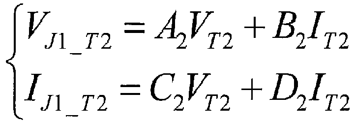
- The further voltage and current phasors for junction J1 with respect to terminal T2 are calculated by the following equations:
where,




- z 2 is the impedance per length of the further power transmission section interconnecting junction J1 to terminal T2;
- y 2 is the admittance per length of the further power transmission section interconnecting junction J1 to terminal T2;
- l T2 is the line length of the further power transmission section interconnecting junction J1 to terminal T2.
- The further voltage and current phasors for junction J2 with respect to terminal T3 are calculated by the following equations:

where,


- z 3 is the impedance per length of the further power transmission section interconnecting junction J2 to terminal T3;
- y 3 is the admittance per length of the further power transmission section interconnecting junction J2 to terminal T3;
- l T3 is the line length of the further power transmission section interconnecting junction J2 to terminal T3.
- The further voltage and current phasors for junction J3 with respect to terminal T4 are calculated by the following equations:

where,


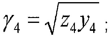

- z 4 is the impedance per length of the further power transmission section interconnecting junction J3 to terminal T4;
- y 4 is the admittance per length of the further power transmission section interconnecting junction J3 to terminal T4;
- l T4 is the line length of the further power transmission section interconnecting junction J3 to terminal T4.
- The further voltage and current phasors for junction J4 with respect to terminal T5 are calculated by the following equations:


- z 5 is the impedance per length of the further power transmission section interconnecting junction J4 to terminal T5;
- y 5 is the admittance of the further power transmission section interconnecting junction J4 to terminal T5;
- l T5 is the line length of the further power transmission section interconnecting junction J4 to terminal T5).
- The first and second sets of voltage phasors VJL,VVR and the further voltage phasors VJT are then fed into Block B to compare the voltage phasors to identify the power transmission section or junction corresponding to the location of the fault, as follows. The following steps are illustrated in the flow diagram of
Figure 4 . - A subtraction voltage phasor for each junction is obtained. In this regard the subtraction voltage phasor of each junction is equal to the difference between the corresponding voltage phasors of the first and second sets of voltage phasors VJL,VJR, as shown in the following equation.

- Then the minimum amplitude value (modular) ΔVmin of the plurality of subtraction voltage phasors ΔVJ is determined using the equation: ΔVmin = min{|ΔVJk|, k = 0,1,2,3,4,5}.
- The minimum amplitude value ΔVmin is subsequently compared with a predefined voltage threshold Vthres1 to determine whether ΔVmin is less than Vthres1. In
Figure 4 , Vthres1 is exemplarily set at 0.02 times of the rated voltage of the power transmission scheme so that, for example, if the rated voltage is 110 V, then Vthres1 is 2.2 V. - If the minimum amplitude value ΔVmin is less than the predefined voltage threshold Vthres1, it indicates that the fault is either on the junction corresponding to the minimum amplitude value ΔVmin or in the further power transmission section connected to this junction. For example, if |ΔVJ3|=ΔVmin, it indicates that the fault is either on the junction J3 or in the further power transmission section interconnecting the junction J3 and the terminal T4.
- Subsequently the location of the fault is more accurately determined by using the discriminative criterion of |VJkL-VJk_Tn| > Vthres2, where ΔVmin = VJkL. Therefore, for example, if |ΔVJ3|=ΔVmin, the discriminative criterion is |VJ3L-VJ3_T4| > Vthres2. In
Figure 4 , Vthres1 is exemplarily set at 0.05 times of the rated voltage of the power transmission scheme so that, for example, if the rated voltage is 110 V, then Vthres1 is 5.5 V. - If |VJkL-VJk_Tn| > Vthres2, then the fault is located in the further power transmission section interconnecting the kth junction and the nth terminal. If |VJkL-VJk_Tn| <= Vthres2, then the fault is located on the kth junction. If there are multiple terminals connected to the junction in question, the discriminative criterion is applied to each terminal in turn.
- If the minimum amplitude value ΔVmin is more than the predefined voltage threshold Vthres1, it indicates that the fault is in the power transmission section interconnecting the kth junction and the k+1th junction. For example, if |ΔVJ3|=ΔVmin, it indicates that the fault is in the power transmission sections interconnecting the junctions J0,J1,J2,J3,J4,J5.
- Subsequently the location of the fault is more accurately determined by comparing the voltage phasor of a given junction with the voltage phasor of a neighbouring junction to identify the power transmission section corresponding to the location of the fault.
- Different criterion may be applied to determine the power transmission section in which the fault is located.
- In a first exemplary criterion, the power transmission section in which the fault is located is determined by comparing the phases of the subtraction voltage phasor ΔVJk of a given junction and the subtraction voltage phasor ΔVJk+1 of a neighbouring junction to check whether the comparison meets the following criterion:
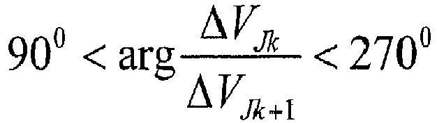
- If the criterion is met, then the fault is located in the power transmission section interconnecting junctions Jk and Jk+1.
- In a second exemplary criterion, the power transmission section in which the fault is located is determined by comparing the amplitudes of the subtraction voltage phasor ΔVJk of a given junction and the subtraction voltage phasor ΔVJk+1 of a neighbouring junction to check whether an amplitude comparison meets the following criterion:

- If the criterion is met, then the fault is located in the power transmission section interconnecting junctions Jk and Jk+1.
- In a third exemplary criterion, the power transmission section in which the fault is located is determined by comparing the subtraction voltage phasor ΔVJk of a given junction and the subtraction voltage phasor ΔVJk+1 of a neighbouring junction to check whether the comparison meets the following criterion.

- If the criterion is met, then the fault is located in the power transmission section interconnecting junctions Jk and Jk+1.
- If a given power transmission section is identified as the location of the fault, Block C then selects the appropriate voltage and current phasors from VJL, VJR, IJL and IJR and forms a two-ended system equivalent of the power transmission section identified as the location of the fault with voltages and currents VM, VN, IM, IN.
- If the relevant power transmission section is connected between junctions Jk and Jk+1, the voltage and current phasors VJkL, IJk_k+1L, VJk+1R, IJk+1,kR are selected to form the two-ended system equivalent such that: VM = VJkL; IM = IJk_k+1L; VN = VJk+1R; and IN = IJk+1_kR. That is, junction Jk is the equivalent end M of the two-ended system equivalent, and junction Jk+1 is the equivalent N of the two-ended system equivalent.
- If the relevant power transmission section is a further power transmission section interconnecting a junction Jk and a terminal Tn, Block C then selects the voltage and current phasors at the terminal Tn, the voltage phasor VJkL,VJkR at the junction to which the terminal Tn is connected, and the negative summation of the corresponding current phasors of the first and second sets of current phasors -(IJk, k+1L+IJk,k-1R), such that: VM = VTn; IM = ITn; VN = VJkL, IN = -(IJk,k+1L +IJk_k-1R). That is, terminal Tn is the equivalent end M of the two-ended system equivalent, and junction Jk is the equivalent end N of the two-ended system equivalent.
- Based on the two-ended system equivalent the distance of the fault along the power transmission section is determined on the basis of the voltage and currents VM,VN,IM,IN of the two-ended system equivalent. In the apparatus of
Figure 2 , Block C feeds the voltage and currents VM,VN,IM,IN of the two-ended system equivalent to Block D, which determines the fault distance using the following equation:
- x is the distance to the end M of the two-system equivalent;


- z is the impedance per length of corresponding section, which is settable by customer;
- y is the admittance per length of corresponding section, which is settable by customer;
- I is the line length of corresponding section.
- The above equation can be simplified as:

- In the foregoing manner the method of the invention permits the determination of the location of a fault in a power transmission scheme.
- It will be appreciated that the topology of the power transmission scheme in the embodiment of
Figure 1 is merely chosen to help illustrate the working of the invention, and that the invention is applicable to power transmission schemes based on different topologies. Such power transmission schemes may include, but are not limited to, a different number of power transmissions sections, a different number of junction, a different overall number of terminals, and a different number of terminals connected to each junction. - It is evident from the foregoing description of the method of locating a fault in the power transmission scheme of
Figure 1 that the method of the invention is readily scalable to accommodate different topologies of the power transmission scheme. - It will be also appreciated that the power transmission scheme of
Figure 1 may form the whole of a power transmission network or part of a more complex power transmission network. - It will be further appreciated that the values for the parameters described herein are merely chosen to help illustrate the working of the invention, and that these values may vary depending on the application of the power transmission scheme.
Claims (15)
- A method of locating a fault in a power transmission scheme, the power transmission scheme including a plurality of power transmission sections and a plurality of connection points, the plurality of connection points including a first end connection point, a second end connection point and at least one intermediate connection point connected between the first and second end connection points, each of the plurality of power transmission sections arranged to interconnect a respective two of the plurality of connection points such that the plurality of power transmission sections are connected successively between the first and second end connection points and such that the or each intermediate connection point interconnects a or a respective neighbouring pair of the power transmission sections, the method comprising the steps of:(i) measuring first and second end voltage phasors at the first and second end connection points respectively;(ii) obtaining a first set of voltage phasors, wherein the first set of voltage phasors includes the measured first end voltage phasor and further includes respective voltage phasors at each of the second and intermediate connection points that are determined based on the measured first end voltage phasor;(iii) obtaining a second set of voltage phasors, wherein the second set of voltage phasors includes the measured second end voltage phasor and further includes respective voltage phasors at each of the first and intermediate connection points that are determined based on the measured second end voltage phasor;(iv) comparing the first and second sets of voltage phasors to identify the power transmission section or connection point corresponding to the location of the fault, wherein each voltage phasor of the first set of voltage phasors is compared to the respective voltage phasor of the second set of voltage phasors that corresponds to the same connection point.
- A method according to Claim 1 further including the steps of:• measuring first and second end current phasors at the first and second end connection points respectively;• obtaining the first set of voltage phasors, wherein the first set of voltage phasors includes the measured first end voltage phasor and further includes respective voltage phasors at each of the second and intermediate connection points that are determined based on the measured first end voltage and current phasors;• obtaining the second set of voltage phasors, wherein the second set of voltage phasors includes the measured second end voltage phasor and further includes respective voltage phasors at each of the first and intermediate connection points that are determined based on the measured second end voltage and current phasors.
- A method according to any one of the preceding claims wherein the power transmission section connected to the first connection point is a first power transmission section, the power transmission section connected to the second connection point is a second power transmission section, the or each other power transmission section connected between the or the respective neighbouring pair of intermediate connection points is an intermediate power transmission section, the method further including the steps of:• measuring first and second end current phasors at the first and second end connection points respectively;• obtaining a first set of current phasors, wherein the first set of current phasors includes respective current phasors in the first, second and intermediate power transmission sections that are determined based on the measured first end voltage and current phasors;• obtaining a second set of current phasors, wherein the second set of current phasors includes respective current phasors in the first, second and intermediate power transmission sections that are determined based on the measured second end voltage and current phasors.
- A method according to Claim 3 wherein the respective voltage phasors at the second and intermediate connection points of the first set of voltage phasors are determined based on the measured first end voltage phasor and the first set of current phasors, and the respective voltage phasors at the first and intermediate connection points of the second set of voltage phasors are determined based on the measured second end voltage phasor and the second set of current phasors.
- A method according to any one of the preceding claims wherein the power transmission scheme further includes a further power transmission section connecting the intermediate connection point to a further connection point or a plurality of further power transmission sections each connecting a respective one of the intermediate connection points to a respective one of a plurality of further connection points, the method further including the steps of:• measuring a or a respective voltage phasor at the or each further connection point;• measuring a or a respective current phasor at the or each further connection point;• determining a or a respective further current phasor flowing into the corresponding intermediate connection point and in the or each further power transmission section based on the measured voltage and current phasors of the corresponding further connection point.
- A method according to Claim 5 when dependent from Claim 3 or Claim 4 wherein the respective current phasors in the first, second and intermediate power transmission sections of the first set of current phasors are determined based on the measured first end voltage and current phasors and the or each further current phasor, and the respective current phasors in the first, second and intermediate power transmission sections of the second set of current phasors are determined based on the measured second end voltage and current phasors and the or each further current phasor.
- A method according to any one of the preceding claims wherein the power transmission scheme further includes a further power transmission section connecting the intermediate connection point to a further connection point or a plurality of further power transmission sections each connecting a respective one of the intermediate connection points to a respective one of a plurality of further connection points, the method further including the steps of:• measuring a or a respective voltage phasor at the or each further connection point;• measuring a or a respective current phasor at the or each further connection point;• determining a or a respective further voltage phasor at the or each intermediate connection point based on the measured voltage and current phasors of the corresponding further connection point.
- A method according to any one of the preceding claims wherein the step of comparing the first and second sets of voltage phasors includes:• obtaining a subtraction voltage phasor of each connection point, wherein the subtraction voltage phasor of each connection point is equal to the difference between the corresponding voltage phasors of the first and second sets of voltage phasors;• determining the minimum amplitude value of the plurality of subtraction voltage phasors;• comparing the minimum amplitude value with a predefined criterion threshold to identify the power transmission section or connection point corresponding to the location of the fault.
- A method according to Claim 8 when dependent from Claim 7 wherein the step of comparing the first and second sets of voltage phasors includes:• if the minimum amplitude value is less than the predefined criterion threshold, comparing the voltage phasor and further voltage phasor of the intermediate connection point to determine whether the location of the fault is on the intermediate connection point or in the further power transmission section corresponding to the minimum amplitude value.
- A method according to Claim 8 or Claim 9 wherein the step of comparing the first and second sets of voltage phasors further includes:• if the minimum amplitude value is more than the predefined criterion threshold, comparing the voltage phasors of the connection point corresponding to the minimum amplitude value with the voltage phasors of a neighbouring connection point to identify the power transmission section corresponding to the location of the fault.
- A method according to Claim 10 wherein the step of comparing the first and second sets of voltage phasors further includes:• if the minimum amplitude value is more than the predefined criterion threshold, comparing the phase or amplitude of the subtraction voltage phasor of the connection point corresponding to the minimum amplitude value with the phase or amplitude of the subtraction voltage phasor of a neighbouring connection point to identify the power transmission section corresponding to the location of the fault.
- A method according to any one of the preceding claims further including the step of: if a given power transmission section is identified as the location of the fault, using the corresponding voltages and currents to form a two-ended system equivalent of the power transmission section identified as the location of the fault.
- A method according to Claim 12 further including the step of determining the distance of the fault along the power transmission section on the basis of the voltage and currents of the two-ended system equivalent.
- An apparatus for locating a fault in a power transmission scheme, the power transmission scheme including a plurality of power transmission sections and a plurality of connection points, the plurality of connection points including a first end connection point, a second end connection point and at least one intermediate connection point connected between the first and second end connection points, each of the plurality of power transmission sections arranged to interconnect a respective two of the plurality of connection points such that the plurality of power transmission sections are connected successively between the first and second end connection points and such that the or each intermediate connection point interconnects a or a respective neighbouring pair of the power transmission sections, the apparatus configured to:(i) measure first and second end voltage phasors at the first and second end connection points respectively;(ii) obtain a first set of voltage phasors, wherein the first set of voltage phasors includes the measured first end voltage phasor and further includes respective voltage phasors at each of the second and intermediate connection points that are determined based on the measured first end voltage phasor;(iii) obtain a second set of voltage phasors, wherein the second set of voltage phasors includes the measured second end voltage phasor and further includes respective voltage phasors at each of the first and intermediate connection points that are determined based on the measured second end voltage phasor;(iv) compare the first and second sets of voltage phasors to identify the power transmission section or connection point corresponding to the location of the fault, wherein each voltage phasor of the first set of voltage phasors is compared to the respective voltage phasor of the second set of voltage phasors that corresponds to the same connection point.
- A power transmission scheme including a plurality of power transmission sections and a plurality of connection points, the plurality of connection points including a first end connection point, a second end connection point and at least one intermediate connection point connected between the first and second end connection points, each of the plurality of power transmission sections arranged to interconnect a respective two of the plurality of connection points such that the plurality of power transmission sections are connected successively between the first and second end connection points and such that the or each intermediate connection point interconnects a or a respective neighbouring pair of the power transmission sections, wherein the power transmission scheme further includes the apparatus of Claim 14.
Priority Applications (8)
| Application Number | Priority Date | Filing Date | Title |
|---|---|---|---|
| EP16275017.8A EP3203248B1 (en) | 2016-02-02 | 2016-02-02 | Method of locating a fault in a power transmission scheme |
| US16/074,797 US10830807B2 (en) | 2016-02-02 | 2017-02-02 | Method of locating a fault in a power transmission scheme |
| CA3012751A CA3012751A1 (en) | 2016-02-02 | 2017-02-02 | Method of locating a fault in a power transmission scheme |
| BR112018015516A BR112018015516A2 (en) | 2016-02-02 | 2017-02-02 | method and apparatus for locating a fault in a power transmission scheme and power transmission scheme |
| JP2018539944A JP2019503642A (en) | 2016-02-02 | 2017-02-02 | How to find faults in power transmission systems |
| CN201780009737.1A CN108603910B (en) | 2016-02-02 | 2017-02-02 | Method for locating faults in power transmission schemes |
| PCT/EP2017/052205 WO2017134136A1 (en) | 2016-02-02 | 2017-02-02 | Method of locating a fault in a power transmission scheme |
| MX2018009359A MX382920B (en) | 2016-02-02 | 2017-02-02 | METHOD OF LOCATING A FAULT IN A POWER TRANSMISSION SCHEME. |
Applications Claiming Priority (1)
| Application Number | Priority Date | Filing Date | Title |
|---|---|---|---|
| EP16275017.8A EP3203248B1 (en) | 2016-02-02 | 2016-02-02 | Method of locating a fault in a power transmission scheme |
Publications (2)
| Publication Number | Publication Date |
|---|---|
| EP3203248A1 true EP3203248A1 (en) | 2017-08-09 |
| EP3203248B1 EP3203248B1 (en) | 2023-11-22 |
Family
ID=55300450
Family Applications (1)
| Application Number | Title | Priority Date | Filing Date |
|---|---|---|---|
| EP16275017.8A Active EP3203248B1 (en) | 2016-02-02 | 2016-02-02 | Method of locating a fault in a power transmission scheme |
Country Status (8)
| Country | Link |
|---|---|
| US (1) | US10830807B2 (en) |
| EP (1) | EP3203248B1 (en) |
| JP (1) | JP2019503642A (en) |
| CN (1) | CN108603910B (en) |
| BR (1) | BR112018015516A2 (en) |
| CA (1) | CA3012751A1 (en) |
| MX (1) | MX382920B (en) |
| WO (1) | WO2017134136A1 (en) |
Families Citing this family (5)
| Publication number | Priority date | Publication date | Assignee | Title |
|---|---|---|---|---|
| EP3662553A1 (en) * | 2017-08-04 | 2020-06-10 | ABB Power Grids Switzerland AG | Method and device for fault section identification in multi-terminal mixed lines |
| US11035896B2 (en) * | 2018-05-22 | 2021-06-15 | Guangdong University Of Technology | Method and device for reliability assessment of wide area protection system |
| CN109580463B (en) * | 2018-11-22 | 2021-08-20 | 国网天津市电力公司电力科学研究院 | A method for measuring the corrosion degree of grounding grid |
| CN113219298B (en) * | 2021-03-24 | 2022-10-11 | 昆明理工大学 | Fault current traveling wave numerical simulation method for complex alternating current power grid |
| EP4724825A1 (en) * | 2023-06-09 | 2026-04-15 | Zaphiro Technologies SA | Directional fault locating in a power network |
Citations (1)
| Publication number | Priority date | Publication date | Assignee | Title |
|---|---|---|---|---|
| US20140229127A1 (en) * | 2013-02-13 | 2014-08-14 | Alstom Grid, Inc. | Electrical fault location determination in a distribution system based on phasor information |
Family Cites Families (5)
| Publication number | Priority date | Publication date | Assignee | Title |
|---|---|---|---|---|
| RU2397503C2 (en) * | 2005-09-14 | 2010-08-20 | Абб Текнолоджи Аг | Method of determining point of fault in power line |
| CN100549710C (en) * | 2007-06-22 | 2009-10-14 | 北京四方继保自动化股份有限公司 | Utilize distribution parameter to realize the two ends of electric transmission line distance-finding method |
| US8072715B2 (en) * | 2008-07-16 | 2011-12-06 | Huntington Ingalls Incorporated | Method, apparatus and computer program product for fault protection |
| CN103197204B (en) * | 2013-04-07 | 2015-04-29 | 山东电力集团公司德州供电公司 | Mixed type method of multi-terminal circuit fault location |
| US9476930B2 (en) * | 2014-02-07 | 2016-10-25 | Mitsubishi Electric Research Laboratories, Inc. | Locating multi-phase faults in ungrounded power distribution systems |
-
2016
- 2016-02-02 EP EP16275017.8A patent/EP3203248B1/en active Active
-
2017
- 2017-02-02 WO PCT/EP2017/052205 patent/WO2017134136A1/en not_active Ceased
- 2017-02-02 CN CN201780009737.1A patent/CN108603910B/en not_active Expired - Fee Related
- 2017-02-02 US US16/074,797 patent/US10830807B2/en active Active
- 2017-02-02 BR BR112018015516A patent/BR112018015516A2/en not_active IP Right Cessation
- 2017-02-02 MX MX2018009359A patent/MX382920B/en unknown
- 2017-02-02 JP JP2018539944A patent/JP2019503642A/en active Pending
- 2017-02-02 CA CA3012751A patent/CA3012751A1/en active Pending
Patent Citations (1)
| Publication number | Priority date | Publication date | Assignee | Title |
|---|---|---|---|---|
| US20140229127A1 (en) * | 2013-02-13 | 2014-08-14 | Alstom Grid, Inc. | Electrical fault location determination in a distribution system based on phasor information |
Also Published As
| Publication number | Publication date |
|---|---|
| MX382920B (en) | 2025-03-13 |
| US20190041448A1 (en) | 2019-02-07 |
| WO2017134136A1 (en) | 2017-08-10 |
| CN108603910B (en) | 2021-08-24 |
| BR112018015516A2 (en) | 2018-12-26 |
| EP3203248B1 (en) | 2023-11-22 |
| CN108603910A (en) | 2018-09-28 |
| MX2018009359A (en) | 2018-12-19 |
| CA3012751A1 (en) | 2017-08-10 |
| US10830807B2 (en) | 2020-11-10 |
| JP2019503642A (en) | 2019-02-07 |
Similar Documents
| Publication | Publication Date | Title |
|---|---|---|
| EP3203248B1 (en) | Method of locating a fault in a power transmission scheme | |
| EP1172660B1 (en) | Method and device for fault location in distribution networks | |
| RU2571629C1 (en) | Method and device for assessment of angle of zero-phase-sequence voltage at single line-to-ground fault | |
| EP1342096B1 (en) | Method and device for fault location | |
| JP6242354B2 (en) | Failure place analysis method and system for ungrounded distribution system | |
| EP3482472B1 (en) | A method and system for locating a fault in a mixed power transmission line | |
| EP2000811B1 (en) | Method for determining location of phase-to-earth fault | |
| US20180284180A1 (en) | Fault location detection and distance protection apparatus and associated method | |
| US20070021937A1 (en) | Apparatus and method for compensating secondary currents used in differential protection to correct for a phase shift introduced between high voltage and low voltage transformer windings | |
| EP3369150B1 (en) | Method and system for protection in a mixed line | |
| EP1018027B1 (en) | Method for the location of a high-resistance earth fault in a power distribution system on the basis of current measurements | |
| US8274294B2 (en) | Method and device for capturing a fault in an electrical supply grid | |
| US20190331726A1 (en) | Method of locating a fault in a power transmission scheme | |
| EP3299826A1 (en) | Method to estimate an equivalent grid impedance for power generators | |
| Hossain et al. | Distribution high impedance fault location using localized voltage magnitude measurements | |
| CN100550556C (en) | Method and device for plausibility testing of voltage transformers and electrical switching installations | |
| JP4906498B2 (en) | Ground fault location method and orientation device | |
| EP3141918B1 (en) | Improvements in or relating to determining a fault location in a power transmission medium | |
| EP4488696B1 (en) | Fault location detection in tapped power distribution lines | |
| RU2793555C1 (en) | Method for determining location of a short circuit on an overhead power line with unsynchronized measurements from its two ends | |
| US20240372365A1 (en) | Method and system for an electricity distribution line | |
| KR20230156591A (en) | Power facility measurement phase verification device and method | |
| Blanco et al. | Algorithm for relative location of voltage sags and capacitor switching transients based on voltage measurements only | |
| CN121410441A (en) | A method and device for locating single-phase ground fault sections | |
| Tanaka et al. | Estimation of system voltage sag profile using recorded sag data |
Legal Events
| Date | Code | Title | Description |
|---|---|---|---|
| PUAI | Public reference made under article 153(3) epc to a published international application that has entered the european phase |
Free format text: ORIGINAL CODE: 0009012 |
|
| STAA | Information on the status of an ep patent application or granted ep patent |
Free format text: STATUS: THE APPLICATION HAS BEEN PUBLISHED |
|
| AK | Designated contracting states |
Kind code of ref document: A1 Designated state(s): AL AT BE BG CH CY CZ DE DK EE ES FI FR GB GR HR HU IE IS IT LI LT LU LV MC MK MT NL NO PL PT RO RS SE SI SK SM TR |
|
| AX | Request for extension of the european patent |
Extension state: BA ME |
|
| STAA | Information on the status of an ep patent application or granted ep patent |
Free format text: STATUS: REQUEST FOR EXAMINATION WAS MADE |
|
| 17P | Request for examination filed |
Effective date: 20180209 |
|
| RBV | Designated contracting states (corrected) |
Designated state(s): AL AT BE BG CH CY CZ DE DK EE ES FI FR GB GR HR HU IE IS IT LI LT LU LV MC MK MT NL NO PL PT RO RS SE SI SK SM TR |
|
| STAA | Information on the status of an ep patent application or granted ep patent |
Free format text: STATUS: EXAMINATION IS IN PROGRESS |
|
| 17Q | First examination report despatched |
Effective date: 20210520 |
|
| GRAP | Despatch of communication of intention to grant a patent |
Free format text: ORIGINAL CODE: EPIDOSNIGR1 |
|
| STAA | Information on the status of an ep patent application or granted ep patent |
Free format text: STATUS: GRANT OF PATENT IS INTENDED |
|
| INTG | Intention to grant announced |
Effective date: 20230605 |
|
| P01 | Opt-out of the competence of the unified patent court (upc) registered |
Effective date: 20230522 |
|
| GRAS | Grant fee paid |
Free format text: ORIGINAL CODE: EPIDOSNIGR3 |
|
| GRAA | (expected) grant |
Free format text: ORIGINAL CODE: 0009210 |
|
| STAA | Information on the status of an ep patent application or granted ep patent |
Free format text: STATUS: THE PATENT HAS BEEN GRANTED |
|
| AK | Designated contracting states |
Kind code of ref document: B1 Designated state(s): AL AT BE BG CH CY CZ DE DK EE ES FI FR GB GR HR HU IE IS IT LI LT LU LV MC MK MT NL NO PL PT RO RS SE SI SK SM TR |
|
| REG | Reference to a national code |
Ref country code: GB Ref legal event code: FG4D |
|
| REG | Reference to a national code |
Ref country code: CH Ref legal event code: EP Ref country code: DE Ref legal event code: R096 Ref document number: 602016084251 Country of ref document: DE |
|
| REG | Reference to a national code |
Ref country code: IE Ref legal event code: FG4D |
|
| REG | Reference to a national code |
Ref country code: SE Ref legal event code: TRGR Ref country code: LT Ref legal event code: MG9D |
|
| REG | Reference to a national code |
Ref country code: NL Ref legal event code: MP Effective date: 20231122 |
|
| PG25 | Lapsed in a contracting state [announced via postgrant information from national office to epo] |
Ref country code: GR Free format text: LAPSE BECAUSE OF FAILURE TO SUBMIT A TRANSLATION OF THE DESCRIPTION OR TO PAY THE FEE WITHIN THE PRESCRIBED TIME-LIMIT Effective date: 20240223 |
|
| PG25 | Lapsed in a contracting state [announced via postgrant information from national office to epo] |
Ref country code: IS Free format text: LAPSE BECAUSE OF FAILURE TO SUBMIT A TRANSLATION OF THE DESCRIPTION OR TO PAY THE FEE WITHIN THE PRESCRIBED TIME-LIMIT Effective date: 20240322 |
|
| PG25 | Lapsed in a contracting state [announced via postgrant information from national office to epo] |
Ref country code: LT Free format text: LAPSE BECAUSE OF FAILURE TO SUBMIT A TRANSLATION OF THE DESCRIPTION OR TO PAY THE FEE WITHIN THE PRESCRIBED TIME-LIMIT Effective date: 20231122 |
|
| REG | Reference to a national code |
Ref country code: AT Ref legal event code: MK05 Ref document number: 1634296 Country of ref document: AT Kind code of ref document: T Effective date: 20231122 |
|
| PG25 | Lapsed in a contracting state [announced via postgrant information from national office to epo] |
Ref country code: NL Free format text: LAPSE BECAUSE OF FAILURE TO SUBMIT A TRANSLATION OF THE DESCRIPTION OR TO PAY THE FEE WITHIN THE PRESCRIBED TIME-LIMIT Effective date: 20231122 |
|
| PG25 | Lapsed in a contracting state [announced via postgrant information from national office to epo] |
Ref country code: AT Free format text: LAPSE BECAUSE OF FAILURE TO SUBMIT A TRANSLATION OF THE DESCRIPTION OR TO PAY THE FEE WITHIN THE PRESCRIBED TIME-LIMIT Effective date: 20231122 |
|
| PG25 | Lapsed in a contracting state [announced via postgrant information from national office to epo] |
Ref country code: ES Free format text: LAPSE BECAUSE OF FAILURE TO SUBMIT A TRANSLATION OF THE DESCRIPTION OR TO PAY THE FEE WITHIN THE PRESCRIBED TIME-LIMIT Effective date: 20231122 |
|
| PG25 | Lapsed in a contracting state [announced via postgrant information from national office to epo] |
Ref country code: NL Free format text: LAPSE BECAUSE OF FAILURE TO SUBMIT A TRANSLATION OF THE DESCRIPTION OR TO PAY THE FEE WITHIN THE PRESCRIBED TIME-LIMIT Effective date: 20231122 Ref country code: LT Free format text: LAPSE BECAUSE OF FAILURE TO SUBMIT A TRANSLATION OF THE DESCRIPTION OR TO PAY THE FEE WITHIN THE PRESCRIBED TIME-LIMIT Effective date: 20231122 Ref country code: IS Free format text: LAPSE BECAUSE OF FAILURE TO SUBMIT A TRANSLATION OF THE DESCRIPTION OR TO PAY THE FEE WITHIN THE PRESCRIBED TIME-LIMIT Effective date: 20240322 Ref country code: GR Free format text: LAPSE BECAUSE OF FAILURE TO SUBMIT A TRANSLATION OF THE DESCRIPTION OR TO PAY THE FEE WITHIN THE PRESCRIBED TIME-LIMIT Effective date: 20240223 Ref country code: ES Free format text: LAPSE BECAUSE OF FAILURE TO SUBMIT A TRANSLATION OF THE DESCRIPTION OR TO PAY THE FEE WITHIN THE PRESCRIBED TIME-LIMIT Effective date: 20231122 Ref country code: BG Free format text: LAPSE BECAUSE OF FAILURE TO SUBMIT A TRANSLATION OF THE DESCRIPTION OR TO PAY THE FEE WITHIN THE PRESCRIBED TIME-LIMIT Effective date: 20240222 Ref country code: AT Free format text: LAPSE BECAUSE OF FAILURE TO SUBMIT A TRANSLATION OF THE DESCRIPTION OR TO PAY THE FEE WITHIN THE PRESCRIBED TIME-LIMIT Effective date: 20231122 Ref country code: PT Free format text: LAPSE BECAUSE OF FAILURE TO SUBMIT A TRANSLATION OF THE DESCRIPTION OR TO PAY THE FEE WITHIN THE PRESCRIBED TIME-LIMIT Effective date: 20240322 |
|
| PG25 | Lapsed in a contracting state [announced via postgrant information from national office to epo] |
Ref country code: RS Free format text: LAPSE BECAUSE OF FAILURE TO SUBMIT A TRANSLATION OF THE DESCRIPTION OR TO PAY THE FEE WITHIN THE PRESCRIBED TIME-LIMIT Effective date: 20231122 Ref country code: PL Free format text: LAPSE BECAUSE OF FAILURE TO SUBMIT A TRANSLATION OF THE DESCRIPTION OR TO PAY THE FEE WITHIN THE PRESCRIBED TIME-LIMIT Effective date: 20231122 Ref country code: NO Free format text: LAPSE BECAUSE OF FAILURE TO SUBMIT A TRANSLATION OF THE DESCRIPTION OR TO PAY THE FEE WITHIN THE PRESCRIBED TIME-LIMIT Effective date: 20240222 Ref country code: LV Free format text: LAPSE BECAUSE OF FAILURE TO SUBMIT A TRANSLATION OF THE DESCRIPTION OR TO PAY THE FEE WITHIN THE PRESCRIBED TIME-LIMIT Effective date: 20231122 Ref country code: HR Free format text: LAPSE BECAUSE OF FAILURE TO SUBMIT A TRANSLATION OF THE DESCRIPTION OR TO PAY THE FEE WITHIN THE PRESCRIBED TIME-LIMIT Effective date: 20231122 |
|
| PG25 | Lapsed in a contracting state [announced via postgrant information from national office to epo] |
Ref country code: DK Free format text: LAPSE BECAUSE OF FAILURE TO SUBMIT A TRANSLATION OF THE DESCRIPTION OR TO PAY THE FEE WITHIN THE PRESCRIBED TIME-LIMIT Effective date: 20231122 |
|
| PG25 | Lapsed in a contracting state [announced via postgrant information from national office to epo] |
Ref country code: CZ Free format text: LAPSE BECAUSE OF FAILURE TO SUBMIT A TRANSLATION OF THE DESCRIPTION OR TO PAY THE FEE WITHIN THE PRESCRIBED TIME-LIMIT Effective date: 20231122 |
|
| PG25 | Lapsed in a contracting state [announced via postgrant information from national office to epo] |
Ref country code: SK Free format text: LAPSE BECAUSE OF FAILURE TO SUBMIT A TRANSLATION OF THE DESCRIPTION OR TO PAY THE FEE WITHIN THE PRESCRIBED TIME-LIMIT Effective date: 20231122 |
|
| PG25 | Lapsed in a contracting state [announced via postgrant information from national office to epo] |
Ref country code: SM Free format text: LAPSE BECAUSE OF FAILURE TO SUBMIT A TRANSLATION OF THE DESCRIPTION OR TO PAY THE FEE WITHIN THE PRESCRIBED TIME-LIMIT Effective date: 20231122 Ref country code: SK Free format text: LAPSE BECAUSE OF FAILURE TO SUBMIT A TRANSLATION OF THE DESCRIPTION OR TO PAY THE FEE WITHIN THE PRESCRIBED TIME-LIMIT Effective date: 20231122 Ref country code: RO Free format text: LAPSE BECAUSE OF FAILURE TO SUBMIT A TRANSLATION OF THE DESCRIPTION OR TO PAY THE FEE WITHIN THE PRESCRIBED TIME-LIMIT Effective date: 20231122 Ref country code: IT Free format text: LAPSE BECAUSE OF FAILURE TO SUBMIT A TRANSLATION OF THE DESCRIPTION OR TO PAY THE FEE WITHIN THE PRESCRIBED TIME-LIMIT Effective date: 20231122 Ref country code: EE Free format text: LAPSE BECAUSE OF FAILURE TO SUBMIT A TRANSLATION OF THE DESCRIPTION OR TO PAY THE FEE WITHIN THE PRESCRIBED TIME-LIMIT Effective date: 20231122 Ref country code: DK Free format text: LAPSE BECAUSE OF FAILURE TO SUBMIT A TRANSLATION OF THE DESCRIPTION OR TO PAY THE FEE WITHIN THE PRESCRIBED TIME-LIMIT Effective date: 20231122 Ref country code: CZ Free format text: LAPSE BECAUSE OF FAILURE TO SUBMIT A TRANSLATION OF THE DESCRIPTION OR TO PAY THE FEE WITHIN THE PRESCRIBED TIME-LIMIT Effective date: 20231122 |
|
| REG | Reference to a national code |
Ref country code: DE Ref legal event code: R097 Ref document number: 602016084251 Country of ref document: DE |
|
| PLBE | No opposition filed within time limit |
Free format text: ORIGINAL CODE: 0009261 |
|
| STAA | Information on the status of an ep patent application or granted ep patent |
Free format text: STATUS: NO OPPOSITION FILED WITHIN TIME LIMIT |
|
| PG25 | Lapsed in a contracting state [announced via postgrant information from national office to epo] |
Ref country code: MC Free format text: LAPSE BECAUSE OF FAILURE TO SUBMIT A TRANSLATION OF THE DESCRIPTION OR TO PAY THE FEE WITHIN THE PRESCRIBED TIME-LIMIT Effective date: 20231122 |
|
| REG | Reference to a national code |
Ref country code: CH Ref legal event code: PL |
|
| PG25 | Lapsed in a contracting state [announced via postgrant information from national office to epo] |
Ref country code: LU Free format text: LAPSE BECAUSE OF NON-PAYMENT OF DUE FEES Effective date: 20240202 |
|
| PG25 | Lapsed in a contracting state [announced via postgrant information from national office to epo] |
Ref country code: CH Free format text: LAPSE BECAUSE OF NON-PAYMENT OF DUE FEES Effective date: 20240229 |
|
| PG25 | Lapsed in a contracting state [announced via postgrant information from national office to epo] |
Ref country code: SI Free format text: LAPSE BECAUSE OF FAILURE TO SUBMIT A TRANSLATION OF THE DESCRIPTION OR TO PAY THE FEE WITHIN THE PRESCRIBED TIME-LIMIT Effective date: 20231122 |
|
| 26N | No opposition filed |
Effective date: 20240823 |
|
| PG25 | Lapsed in a contracting state [announced via postgrant information from national office to epo] |
Ref country code: SI Free format text: LAPSE BECAUSE OF FAILURE TO SUBMIT A TRANSLATION OF THE DESCRIPTION OR TO PAY THE FEE WITHIN THE PRESCRIBED TIME-LIMIT Effective date: 20231122 Ref country code: LU Free format text: LAPSE BECAUSE OF NON-PAYMENT OF DUE FEES Effective date: 20240202 Ref country code: CH Free format text: LAPSE BECAUSE OF NON-PAYMENT OF DUE FEES Effective date: 20240229 |
|
| REG | Reference to a national code |
Ref country code: BE Ref legal event code: MM Effective date: 20240229 |
|
| PG25 | Lapsed in a contracting state [announced via postgrant information from national office to epo] |
Ref country code: BE Free format text: LAPSE BECAUSE OF NON-PAYMENT OF DUE FEES Effective date: 20240229 |
|
| PG25 | Lapsed in a contracting state [announced via postgrant information from national office to epo] |
Ref country code: IE Free format text: LAPSE BECAUSE OF NON-PAYMENT OF DUE FEES Effective date: 20240202 |
|
| PG25 | Lapsed in a contracting state [announced via postgrant information from national office to epo] |
Ref country code: IE Free format text: LAPSE BECAUSE OF NON-PAYMENT OF DUE FEES Effective date: 20240202 Ref country code: BE Free format text: LAPSE BECAUSE OF NON-PAYMENT OF DUE FEES Effective date: 20240229 |
|
| PG25 | Lapsed in a contracting state [announced via postgrant information from national office to epo] |
Ref country code: CY Free format text: LAPSE BECAUSE OF FAILURE TO SUBMIT A TRANSLATION OF THE DESCRIPTION OR TO PAY THE FEE WITHIN THE PRESCRIBED TIME-LIMIT; INVALID AB INITIO Effective date: 20160202 |
|
| PG25 | Lapsed in a contracting state [announced via postgrant information from national office to epo] |
Ref country code: HU Free format text: LAPSE BECAUSE OF FAILURE TO SUBMIT A TRANSLATION OF THE DESCRIPTION OR TO PAY THE FEE WITHIN THE PRESCRIBED TIME-LIMIT; INVALID AB INITIO Effective date: 20160202 |
|
| PG25 | Lapsed in a contracting state [announced via postgrant information from national office to epo] |
Ref country code: FI Free format text: LAPSE BECAUSE OF FAILURE TO SUBMIT A TRANSLATION OF THE DESCRIPTION OR TO PAY THE FEE WITHIN THE PRESCRIBED TIME-LIMIT Effective date: 20231122 |
|
| PG25 | Lapsed in a contracting state [announced via postgrant information from national office to epo] |
Ref country code: TR Free format text: LAPSE BECAUSE OF FAILURE TO SUBMIT A TRANSLATION OF THE DESCRIPTION OR TO PAY THE FEE WITHIN THE PRESCRIBED TIME-LIMIT Effective date: 20231122 |
|
| PGFP | Annual fee paid to national office [announced via postgrant information from national office to epo] |
Ref country code: SE Payment date: 20260121 Year of fee payment: 11 |
|
| PGFP | Annual fee paid to national office [announced via postgrant information from national office to epo] |
Ref country code: GB Payment date: 20260121 Year of fee payment: 11 |
|
| PGFP | Annual fee paid to national office [announced via postgrant information from national office to epo] |
Ref country code: DE Payment date: 20260121 Year of fee payment: 11 |
|
| PGFP | Annual fee paid to national office [announced via postgrant information from national office to epo] |
Ref country code: FR Payment date: 20260121 Year of fee payment: 11 |