EP3203122A1 - Dispositif de détection angulaire avec une protection contre les contaminants extérieurs - Google Patents
Dispositif de détection angulaire avec une protection contre les contaminants extérieurs Download PDFInfo
- Publication number
- EP3203122A1 EP3203122A1 EP17305081.6A EP17305081A EP3203122A1 EP 3203122 A1 EP3203122 A1 EP 3203122A1 EP 17305081 A EP17305081 A EP 17305081A EP 3203122 A1 EP3203122 A1 EP 3203122A1
- Authority
- EP
- European Patent Office
- Prior art keywords
- annular
- wall
- movable body
- passage
- seal
- Prior art date
- Legal status (The legal status is an assumption and is not a legal conclusion. Google has not performed a legal analysis and makes no representation as to the accuracy of the status listed.)
- Granted
Links
Images


Classifications
-
- G—PHYSICS
- G01—MEASURING; TESTING
- G01D—MEASURING NOT SPECIALLY ADAPTED FOR A SPECIFIC VARIABLE; ARRANGEMENTS FOR MEASURING TWO OR MORE VARIABLES NOT COVERED IN A SINGLE OTHER SUBCLASS; TARIFF METERING APPARATUS; MEASURING OR TESTING NOT OTHERWISE PROVIDED FOR
- G01D11/00—Component parts of measuring arrangements not specially adapted for a specific variable
- G01D11/24—Housings ; Casings for instruments
-
- F—MECHANICAL ENGINEERING; LIGHTING; HEATING; WEAPONS; BLASTING
- F16—ENGINEERING ELEMENTS AND UNITS; GENERAL MEASURES FOR PRODUCING AND MAINTAINING EFFECTIVE FUNCTIONING OF MACHINES OR INSTALLATIONS; THERMAL INSULATION IN GENERAL
- F16J—PISTONS; CYLINDERS; SEALINGS
- F16J15/00—Sealings
- F16J15/16—Sealings between relatively-moving surfaces
- F16J15/40—Sealings between relatively-moving surfaces by means of fluid
- F16J15/406—Sealings between relatively-moving surfaces by means of fluid by at least one pump
Definitions
- the present invention relates to the field of equipment for installations, machines, vehicles or the like comprising a rotating or rotating part, such as a shaft or an axis, which must be sealed and identified in rotation and / or in rotation. angular position.
- the subject of the present invention is an angular detection device for such a part, with integrated protection against external contaminants, preferably in the form of a dynamic seal, as well as a housing and a bearing comprising such a part and such a device. associated device.
- Fan or blower means in the form of fins mounted on the rotary shaft, are also known for repelling contaminants by creating a discharge air flow (see for example GB 2123498 , CN 202469005 ).
- these detection devices which generally comprise an annular body mounted on the shaft and a circumferential circular structure or housing carrying the sensor (s), themselves form a screen for protection against contaminants when they are arranged in the opening or in the immediate vicinity of the seal already present.
- This protective function can be enhanced by the establishment of a peripheral sealing means between the two bodies in rotary motion relative to each other.
- this solution is not satisfactory and causes significant losses related to friction.
- the object of the present invention is to propose an additional sealing solution in relation to an angular detection device, without the use of additional means.
- the object of the invention consists in particular in proposing a solution making it possible to overcome at least some of the disadvantages set out above, and more particularly able to overcome the aforementioned limitation.
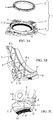
- FIGS 1, 2 and 3A show an angular detection device 1 comprising, on the one hand, a first movable body 2 of generally annular shape, rigidly mounted on a rotating part, for example of the shaft, axle or the like type (not specifically shown), with an axial direction X, and having teeth and / or similar detectable elements 4 distributed in a circumferentially arranged arrangement of said annular body 2 and, secondly, a second fixed body 5 defining a circular opening structure 5 'around and / or opposite the first movable annular body 2.
- This second body 5 carries one or more sensors 5 "capable (s), on the one hand, to individually detect the teeth and / or similar elements 4 of the first movable body 2 during their positioning or passage at a given location and, secondly, to generate a corresponding informative signal.
- the said first and second bodies 2 and 5 delimit between them a passage in form of fent e or circumferential gap (the) 6, possibly with a labyrinthine constitution or baffled (s).
- the first movable body and / or the second fixed body 5 comprises (s) one or more formation (s) 7, 7 ', possibly mutually cooperating, recessed and / or protruding, suitable (s) and intended (s) to generate an air flow FA creating a circumferential dynamic seal at the passage or the gap 6 during the rotation of the rotating part 3, this by cooperation between the two bodies 2 and 5.
- the second fixed body 5 has a wall circular circular extension 8, surrounding the first annular movable body 2, one or formations (s) 7 'in relief or recessed helical configuration, comprising either a single coil 9 extending over the entire inner periphery of said circular wall 8, ie a plurality of portions of successive turns 9 'distributed on the inner periphery of said wall 8.
- the invention proposes a device 1 incorporating means for creating a dynamic seal between the two bodies 2 and 5, without establishing any contact, without requiring separate additional means, without significant constructive modification and without influencing the function of angular detection.
- the air flow FA is ejected on the side of the device 1 opposite the face facing the shaft portion or axis 3 to be sealed.
- This ejection is radially outward with a more or less inclined angle (between 0 ° and 90 °) with respect to the axial direction X, depending on the conformation of the parts 2 and 5 and the passage 6.
- the second fixed body 5 is a directional deflector, concentrator and / or amplifier for the air flow generated by the rotation of the first annular movable body 2 provided with formations 7 providing air entrainment surfaces, such as blades, fins, blades or the like.
- formations 7 providing air entrainment surfaces, such as blades, fins, blades or the like.
- the second fixed body 5 comprises at least a first wall 8 extending axially surrounding the first movable body annular 2 and at least a second wall 8 'extending radially inwardly from the first outer surrounding wall 8, at least partially facing said first annular movable body 2.
- the second fixed body 5 comprises at least one seal material seal 10 intended to cooperate with the first annular movable body 2 to seal the passage-shaped slot or circumferential gap (the) 6 between the two bodies 2 and 5, preferably its opposite end to its ejection opening of the gas flow FA.
- the seal 10 can be very advantageously mounted on the inner contour of the second radially extending wall 8 'in the form of an annular plate, possibly at the free edge of an axial flange 8 "extending said second wall 8 '.
- the two bodies 2 and 5 can be mounted mutually nested (the upper wing of a C extending between the two wings of the other C ), thus constituting a passage 6 with several baffles.
- the second fixed body 5, with circular opening 5 'cooperating with the first annular movable body 2 defines a circumferential annular groove 11 adapted to channel the air flow FA generated by the rotation of said first annular movable body 2.
- the formation (s) 7 'can (wind) be formed (s) in the outer side wall of this groove 11, in which can be circulated the portion of the annular movable body 2 provided with teeth 4 (section C).
- the bodies 2 and 5 each have respective formations 7 and 7 'cooperating functionally with each other to create the dynamic air flow seal during the rotation of the part 3.
- the formations 7 present on the first annular mobile body 2 consist of teeth 4 aerodynamically shaped to generate, when the rotation of said first body 2, and by cooperation with formations 7 'present on the second fixed body 5, the controlled airflow FA forming a dynamic seal.
- teeth 4 may advantageously be identical with the teeth whose detection by the sensor (s) 5 "makes it possible to determine the position and / or the angular displacement of the rotor 2.
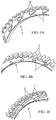
- the first movable annular body 2 is made of sheet metal with at least one radially extending wall, advantageously in the form of an annular plate 8 'and at least one axially extending wall 8, the formations 7 capable of generating an air flow, distributed over its circumference, consisting of vanes, blades or vanes reported on or formed by punctures in at least one of said walls 8, 8 ', in a manner that is not interfering with the teeth or similar detectable elements 4.
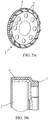
- the first movable annular body 2 comprises an armature with at least one radially extending wall 8 ', advantageously in the form of an annular plate, on which the formations 7 able to generate an air flow, distributed over its circumference, and consisting of blades, vanes or vanes, consist of relief structures obtained by overmolding a synthetic material, possibly simultaneously with the teeth or similar detectable elements 4.
- the invention also relates to a sealed casing (not shown) whose wall is traversed by a rotary shaft, a seal or a seal arrangement being mounted at the passage in the wall.
- This casing is characterized in that a device 1 as described above is installed near the outer opening of said passage so as to provide, in addition to the angular position detection function of the shaft 3, also a function dynamic protection against external contaminants for passage.
- the invention also relates to a bearing for a rotary shaft (not shown), comprising a seal or an arrangement of seals and with which is associated an angular detection device for the position and / or angular movement of the rotary shaft, bearing device characterized in that the angular detection device is a device 1 as mentioned and described herein. -above.
Landscapes
- Engineering & Computer Science (AREA)
- General Engineering & Computer Science (AREA)
- Mechanical Engineering (AREA)
- Physics & Mathematics (AREA)
- General Physics & Mathematics (AREA)
- Indicating Or Recording The Presence, Absence, Or Direction Of Movement (AREA)
- Transmission And Conversion Of Sensor Element Output (AREA)
- Sealing Using Fluids, Sealing Without Contact, And Removal Of Oil (AREA)
Abstract
Description
- La présente invention concerne le domaine des équipements pour installations, machines, véhicules ou analogues comprenant une pièce rotative ou tournante, tel qu'un arbre ou un axe, qu'il y a lieu d'étanchéifier et de repérer en rotation et/ou en position angulaire.
- La présente invention a pour objet un dispositif de détection angulaire pour une telle pièce, avec une protection intégrée contre les contaminants extérieurs, préférentiellement sous la forme d'un joint dynamique, ainsi qu'un carter et un palier comprenant une telle pièce et un tel dispositif associé.
- Dans le contexte des pièces tournantes rotatives, comme par exemple un arbre sortant d'un carter moteur ou d'un arbre porté et guidé dans un palier, l'étanchéité entre le milieu intérieur, dans lequel réside généralement un fluide lubrifiant, et le milieu extérieur est réalisé couramment par un joint statique circulaire dont au moins une lèvre souple est en appui glissant sur l'arbre. De tels joints sont par exemple connus par les documents
FR 2 986 598 EP 2 895 773 ,EP 2 739 885 etFR 3 018 575 - Néanmoins, pour aboutir à une protection satisfaisante, ces dispositifs de joints connus doivent être associés à des éléments d'étanchéité ou des moyens de protection complémentaires en vue de protéger le passage d'arbre et le joint d'étanchéité en place (étanchéité pour les fluides intérieurs) contre les contaminants extérieurs (eau, boue, poussières, ...)
- A titre d'exemples, on peut citer les lèvres pare-poussières (sans contact, mais présence d'un interstice laissant passer les contaminants près de la surface de l'arbre), les joints à lèvres labyrinthe, généralement en fibres non-tissées (en contact avec l'arbre tournant, donc pertes par frottements).
- On connait également des moyens formant ventilateur ou soufflante, sous la forme d'ailettes montées sur l'arbre rotatif, pour repousser les contaminants en créant un flux d'air de refoulement (voir par exemple
GB 2123498 CN 202469005 ). - Dans les différents cas précités, il s'agit de structures supplémentaires spécifiques, entraînant un coût, un encombrement, un poids et une complexité constructive additionnels.
- D'autre part, on connaît des dispositifs de détection de position angulaire destinés à repérer la position et/ou le mouvement en rotation d'un arbre, axe ou pièce rotative analogue.
- Par leur structure et leur présence (voir par exemple
US 6 305 353 ), ces dispositifs de détection, qui comprennent généralement un corps annulaire monté sur l'arbre et une structure ou un logement circulaire circonférentiel portant le(s) capteur(s), forment eux-mêmes un écran de protection contre les contaminants lorsqu'ils sont disposés dans l'ouverture ou à proximité immédiate du joint d'étanchéité déjà présent. Cette fonction de protection peut être renforcée par la mise en place d'un moyen d'étanchéité périphérique entre les deux corps en mouvement rotatif l'un par rapport à l'autre. Toutefois cette solution n'est pas satisfaisante et entraîne des pertes non négligeables liées aux frottements. - La présente invention a pour but de proposer une solution d'étanchéité supplémentaire en relation avec un dispositif de détection angulaire, sans mise en oeuvre d'un moyen additionnel.
- Par le document
US 2014/0374993 , on connaît un dispositif de détection angulaire selon le préambule de la revendication 1, avec notamment des formations destinées à générer un flux d'air. - Toutefois, dans cette construction connue, la totalité des formations générant un flux d'air est présente sur le rotor, ce qui en particulier rend sa construction complexe.
- Le but de l'invention consiste notamment à proposer une solution permettant de surmonter au moins certains des inconvénients exposés précédemment, et plus particulièrement apte à surmonter la limitation précitée.
- Ce but est atteint par les caractéristiques de la partie caractérisante de la revendication 1.
- L'invention sera mieux comprise, grâce à la description ci-après, qui se rapporte à des modes de réalisation préférés, donnés à titre d'exemples non limitatifs, et expliqués avec référence aux dessins schématiques annexés, dans lesquels :
- la
figure 1 est une vue en élévation frontale dans la direction axiale de la pièce rotative (arbre), d'un dispositif de détection angulaire selon l'invention ; - la
figure 2 est une coupe selon A-A, vue partiellement en perspective, du dispositif représentéfigure 1 , l'arbre étant enlevé ; - la
figure 3A est une vue en perspective du dispositif représentéfigure 1 , en accord avec un premier mode de réalisation du second corps fixe, les deux corps constitutifs étant séparés ; - les
figures 3B et 3C sont des vues partielles en perspective de deux portions différentes du second corps fixe représentéfigure 3A ; - les
figures 4A, 4B et 4C sont des vues partielles en perspective de trois variantes d'un premier mode de réalisation du premier corps mobile annulaire faisant partie du dispositif représentéfigures 1 et3A ; - les
figures 5A et 5B sont des vues respectivement en perspective et en coupe (élévation) d'un premier corps annulaire mobile, selon un second mode de réalisation de l'invention, et, - la
figure 6 est une vue en coupe et en perspective d'un second corps fixe selon un second mode de réalisation de l'invention. - Les
figures 1, 2 et3A montrent un dispositif 1 de détection angulaire comprenant, d'une part, un premier corps mobile 2 de forme générale annulaire, monté rigidement sur une pièce rotative, par exemple du type arbre, axe ou analogue (non spécifiquement représentée), avec une direction axiale X, et comportant des dents et/ou des éléments détectables similaires 4 répartie(s) selon un arrangement ordonné sur la circonférence dudit corps annulaire 2 et, d'autre part, un second corps fixe 5 définissant une structure à ouverture circulaire 5' autour et/ou en regard du premier corps annulaire mobile 2. Ce second corps 5 porte un ou des capteur(s) 5" apte (s), d'une part, à détecter individuellement les dents et/ou les éléments similaires 4 du premier corps mobile 2 lors de leur positionnement ou passage au niveau d'un emplacement déterminé et, d'autre part, à générer un signal informatif correspondant. Lesdits premier et second corps 2 et 5 délimitent entre eux un passage en forme de fente ou d'interstice circonférentiel(le) 6, éventuellement avec une constitution labyrinthique ou à chicane(s). - Conformément à l'invention, le premier corps mobile et/ou le second corps fixe 5 comporte(nt) une ou plusieurs formation(s) 7, 7', éventuellement mutuellement coopérantes, en creux et/ou en saillie, apte(s) et destinée(s) à générer un flux d'air FA créant un joint dynamique circonférentiel au niveau du passage ou de l'interstice 6 lors de la rotation de la pièce rotative 3, ce par coopération entre les deux corps 2 et 5.
- Selon l'invention, et comme cela ressort à titre d'exemple des
figures 3 et6 , le second corps fixe 5 présente au niveau d'une paroi circulaire à extension axiale 8, entourant le premier corps mobile annulaire 2, une ou des formation(s) 7' en relief ou en creux à configuration hélicoïdale, comprenant soit une unique spire 9 s'étendant sur tout le pourtour intérieur de ladite paroi circulaire 8, soit une pluralité de portions de spires successives 9' réparties sur le pourtour intérieur de ladite paroi 8. - Ainsi l'invention propose un dispositif 1 intégrant des moyens pour créer un joint dynamique entre les deux corps 2 et 5, ce sans établissement d'un quelconque contact, sans nécessiter de moyens additionnels séparés, sans modification constructive notable et sans influencer la fonction de détection angulaire.
- Le flux d'air FA, généré avantageusement à l'intérieur du passage 6, est éjecté du côté du dispositif 1 opposé à la face tournée vers la portion d'arbre ou d'axe 3 à étanchéifier.
- Cette éjection se fait radialement vers l'extérieur avec un angle plus ou moins incliné (entre 0° et 90°) par rapport à la direction axiale X, en fonction de la conformation des pièces 2 et 5 et du passage 6.
- Préférentiellement, et comme le montrent les
figures 2 ,3B ,3C et6 , le second corps fixe 5 forme déflecteur directionnel, concentrateur et/ou amplificateur pour le flux d'air généré par la rotation du premier corps mobile 2 annulaire pourvu de formations 7 fournissant des surfaces d'entraînement d'air, telles que des pales, des ailettes, des aubes ou analogues. Ainsi, des formations additionnelles spécifiques 7 du premier corps 2 génèrent le flux d'air FA et la configuration du volume entre les deux corps 2 et 5 contribue à sa conformation et à son guidage. Ledit volume interstitiel constitue de ce fait une zone d'obstruction dynamique à tout passage de poussière ou d'agent polluant dans le sens opposé à celui dudit flux d'air FA. - En accord avec une construction avantageuse de l'invention, permettant notamment d'aboutir à un passage 6 à chicanes entre les deux corps 2 et 5, le second corps fixe 5 comporte au moins une première paroi 8 à extension axiale entourant le premier corps mobile annulaire 2 et au moins une seconde paroi 8' s'étendant radialement vers l'intérieur à partir de la première paroi entourante extérieure 8, ce au moins partiellement en regard dudit premier corps mobile annulaire 2.
- Chacune de ces solutions constructives permet de générer des joints dynamiques gazeux avec chacun des caractéristiques spécifiques, en particulier des actions de refoulement par création d'un vortex, d'un tourbillon autour de l'arbre 2.
- Avantageusement, le second corps fixe 5 comporte au moins un joint matériel d'étanchéité 10 destiné à coopérer avec le premier corps mobile annulaire 2 pour étanchéifier le passage en forme de fente ou d'interstice circonférentiel(le) 6 entre les deux corps 2 et 5, préférentiellement son extrémité opposée à son ouverture d'éjection du flux gazeux FA.
- Dans la pratique, le joint d'étanchéité 10 peut être très avantageusement monté sur le contour intérieur de la seconde paroi à extension radiale 8' en forme de plaque annulaire, éventuellement au niveau du bord libre d'une aile axiale 8" prolongeant ladite seconde paroi 8'.
- Dans ce dernier cas, ressortant de la
figure 3C par exemple, les parois 8 et 8' et l'aile 8" forment ensemble, en coupe, une section en C. - Lorsque le premier corps mobile annulaire 2 présente également en coupe une section en C, les deux corps 2 et 5 peuvent être montés de manière mutuellement imbriquée (l'aile supérieure d'un C s'étendant entre les deux ailes de l'autre C), constituant ainsi un passage 6 à plusieurs chicanes.
- Selon une autre caractéristique de l'invention, ressortant des
figures 3C et6 notamment, le second corps fixe 5, à ouverture circulaire 5' coopérante avec le premier corps mobile annulaire 2, définit une rainure annulaire circonférentielle 11 apte à canaliser le flux d'air FA généré par la rotation dudit premier corps mobile annulaire 2. - La ou les formation(s) 7' peut(vent) être formée(s) dans la paroi latérale extérieure de cette rainure 11, dans laquelle peut circuler la partie du corps mobile annulaire 2 pourvue de dents 4 (section en C).
- Comme indiqué précédemment, il est préféré que les corps 2 et 5 présentent chacun des formations 7 et 7' respectives, coopérantes fonctionnellement entre elles pour créer le joint dynamique à flux d'air lors de la rotation de la pièce 3.
- Conformément à un autre aspect de l'invention, et en relation avec un premier mode de réalisation non représenté, il peut être prévu que les formations 7 présentes sur le premier corps mobile annulaire 2 consistent en des dents 4 conformées aérodynamiquement pour générer, lors de la rotation dudit premier corps 2, et par coopération avec des formations 7' présentes sur le second corps fixe 5, le flux d'air contrôlé FA formant joint dynamique.
- Ces dents 4 peuvent avantageusement être identiques avec les dents dont la détection par le(s) capteur(s) 5" permet de déterminer la position et/ou le déplacement angulaire du rotor 2.
- En accord avec un autre mode de réalisation, représenté à titre d'exemple aux
figures 4A à 4C , le premier corps annulaire mobile 2 est réalisé en tôle avec au moins une paroi à extension radiale, avantageusement en forme de plaque annulaire 8' et au moins une paroi à extension axiale 8, les formations 7 aptes à générer un flux d'air, réparties sur sa circonférence, consistant en des pales, aubes ou ailettes rapportées sur ou formées par crevées dans l'une au moins desdites parois 8, 8', de manière non interférentes avec les dents ou éléments détectables analogues 4. - Lorsque les formations 7 sont rapportées, elles peuvent être réalisées par surmoulage ou solidarisation de pièces.
- En accord avec encore un autre mode de réalisation, représenté à titre d'exemple sur les
figures 5A et 5B , le premier corps annulaire mobile 2 comporte une armature avec au moins une paroi à extension radiale 8', avantageusement en forme de plaque annulaire, sur laquelle les formations 7 aptes à générer un flux d'air, réparties sur sa circonférence, et consistant en des pales, des aubes ou des ailettes, sont constituées de structures en relief obtenues par surmoulage d'un matériau synthétique, éventuellement simultanément avec les dents ou les éléments détectables similaires 4. - Bien entendu, les différents types de formations 7, 7' décrits précédemment peuvent être combinés entre eux.
- L'invention concerne également un carter étanche (non représenté) dont la paroi est traversée par un arbre rotatif, un joint d'étanchéité ou un arrangement de joints d'étanchéité étant montés au niveau du passage dans la paroi.
- Ce carter est caractérisé en ce qu'un dispositif 1 tel que décrit précédemment est installé à proximité de l'ouverture extérieure dudit passage de manière à fournir, en plus de la fonction de détection de position angulaire de l'arbre 3, également une fonction de protection dynamique contre les contaminants extérieurs pour le passage.
- Enfin, l'invention porte aussi sur un palier pour arbre rotatif (non représenté), comportant un joint d'étanchéité ou un arrangement de joints d'étanchéité et auquel est associé un dispositif de détection angulaire de la position et/ou du mouvement angulaire de l'arbre rotatif, dispositif de palier caractérisé en ce que le dispositif de détection angulaire est un dispositif 1 tel que mentionné et décrit ci-dessus.
- Bien entendu, l'invention n'est pas limitée aux modes de réalisations décrits et représentés aux dessins annexés. Des modifications restent possibles, notamment du point de vue de la constitution des divers éléments ou par substitution d'équivalents techniques, sans sortir pour autant du domaine de protection de l'invention.
Claims (11)
- Dispositif de détection angulaire comprenant, d'une part, un premier corps mobile (2) de forme générale annulaire, monté rigidement sur une pièce rotative (3), par exemple du type arbre, axe ou analogue, avec une direction axiale, et comportant des dents et/ou des éléments détectables similaires (4) répartie(s) selon un arrangement ordonné sur la circonférence dudit corps annulaire (2) et, d'autre part, un second corps fixe (5) définissant une structure à ouverture circulaire (5') autour et/ou en regard du premier corps annulaire mobile (2), lesdits premier et second corps (2 et 5) délimitant entre eux un passage en forme de fente ou d'interstice circonférentiel(le) (6), éventuellement avec une constitution labyrinthique ou à chicane(s), le premier corps mobile (2) comportant une ou plusieurs formation(s) (7), en creux et/ou en saillie, apte(s) et destinée(s) à générer un flux d'air (FA),
dispositif (1) caractérisé
en ce que le second corps (5) porte avantageusement un ou des capteur(s) (5") apte(s) à détecter individuellement les dents et/ou les éléments similaires (4) du premier corps mobile (2) lors de leur positionnement ou passage au niveau d'un emplacement déterminé et à générer un signal informatif correspondant, et
en ce que le second corps fixe (5) présente au niveau d'une paroi circulaire à extension axiale (8), entourant le premier corps mobile annulaire (2), une ou des formation(s) (7') en relief ou en creux à configuration hélicoïdale, comprenant soit une unique spire (9) s'étendant sur tout le pourtour intérieur de ladite paroi circulaire (8), soit une pluralité de portions de spires successives (9') réparties sur le pourtour intérieur de ladite paroi (8), la ou les formation(s) (7, 7') respectivement du premier corps mobile (2) et du second corps fixe (5) coopérant mutuellement durant la rotation de la pièce rotative (3) de manière à générer un flux d'air (FA)) créant un joint dynamique circonférentiel au niveau du passage ou de l'interstice (6). - Dispositif selon la revendication 1, caractérisé en ce que le second corps fixe (5) forme déflecteur directionnel, concentrateur et/ou amplificateur pour le flux d'air généré par la rotation du premier corps mobile (2) annulaire pourvu de formations (7) fournissant des surfaces d'entraînement d'air, telles que des pales, des ailettes, des aubes ou analogues.
- Dispositif selon la revendication 1 ou 2, caractérisé en ce que le second corps fixe (5) comporte au moins une première paroi (8) à extension axiale entourant le premier corps mobile annulaire (2) et au moins une seconde paroi (8') s'étendant radialement vers l'intérieur à partir de la première paroi entourante extérieure (8), ce au moins partiellement en regard dudit premier corps mobile annulaire (2).
- Dispositif selon l'une quelconque des revendications 1 à 3, caractérisé en ce que le second corps fixe (5) comporte au moins un joint d'étanchéité (10) destiné à coopérer avec le premier corps mobile annulaire (2) pour étanchéifier le passage en forme de fente ou d'interstice circonférentiel(le) (6) entre les deux corps (2 et 5).
- Dispositif selon les revendications 3 et 4, caractérisé en ce que le joint d'étanchéité (10) est monté sur le contour intérieur de la seconde paroi à extension radiale (8') en forme de plaque annulaire, éventuellement au niveau du bord libre d'une aile axiale (8") prolongeant ladite seconde paroi (8').
- Dispositif selon l'une quelconque des revendications 1 à 5, caractérisé en ce que le second corps fixe (5), à ouverture circulaire (5') coopérante avec le premier corps mobile annulaire (2), définit une rainure annulaire circonférentielle (11) apte à canaliser le flux d'air (FA) généré par la rotation dudit premier corps mobile annulaire (2).
- Dispositif selon l'une quelconque des revendications 1 à 6, caractérisé en ce que les formations (7) présentes sur le premier corps mobile annulaire (2) consistent en des dents (4) conformées aérodynamiquement pour générer, lors de la rotation dudit premier corps (2) et par coopération avec des formations (7') présentes sur le second corps fixe (5), le flux d'air contrôlé (FA) formant joint dynamique.
- Dispositif selon l'une quelconque des revendications 1 à 6, caractérisé en ce que le premier corps annulaire mobile (2) est réalisé en tôle avec au moins une paroi à extension radiale, avantageusement en forme de plaque annulaire (8') et au moins une paroi à extension axiale (8), les formations (7) aptes à générer un flux d'air, réparties sur sa circonférence, consistant en des pales, aubes ou ailettes rapportées sur ou formées par crevées dans l'une au moins desdites parois (8, 8'), de manière non interférentes avec les dents ou éléments détectables analogues (4).
- Dispositif selon l'une quelconque des revendications 1 à 6, caractérisé en ce que le premier corps annulaire mobile (2) comporte une armature avec au moins une paroi à extension radiale (8'), avantageusement en forme de plaque annulaire, sur laquelle les formations (7) aptes à générer un flux d'air, réparties sur sa circonférence, et consistant en des pales, des aubes ou des ailettes, sont constituées de structures en relief obtenues par surmoulage d'un matériau synthétique, éventuellement simultanément avec les dents ou les éléments détectables similaires (4).
- Carter étanche dont la paroi est traversée par un arbre rotatif, un joint d'étanchéité ou un arrangement de joints d'étanchéité étant montés au niveau du passage dans la paroi,
carter caractérisé en ce qu'un dispositif (1) selon l'une quelconque des revendications 1 à 9 est installé à proximité de l'ouverture extérieure dudit passage de manière à fournir, en plus de la fonction de détection de position angulaire de l'arbre (3), également une fonction de protection dynamique contre les contaminants extérieurs pour le passage. - Dispositif de palier pour arbre rotatif, comportant un joint d'étanchéité ou un arrangement de joints d'étanchéité et auquel est associé un dispositif de détection angulaire de la position et/ou du mouvement angulaire de l'arbre rotatif, dispositif de palier caractérisé en ce que le dispositif de détection (1) angulaire est un dispositif selon l'une quelconque des revendications 1 à 9.
Applications Claiming Priority (1)
| Application Number | Priority Date | Filing Date | Title |
|---|---|---|---|
| FR1650549A FR3047065A1 (fr) | 2016-01-25 | 2016-01-25 | Dispositif de detection angulaire avec une protection contre les contaminants exterieurs |
Publications (2)
| Publication Number | Publication Date |
|---|---|
| EP3203122A1 true EP3203122A1 (fr) | 2017-08-09 |
| EP3203122B1 EP3203122B1 (fr) | 2018-03-28 |
Family
ID=55486945
Family Applications (1)
| Application Number | Title | Priority Date | Filing Date |
|---|---|---|---|
| EP17305081.6A Active EP3203122B1 (fr) | 2016-01-25 | 2017-01-25 | Dispositif de détection angulaire avec une protection contre les contaminants extérieurs |
Country Status (2)
| Country | Link |
|---|---|
| EP (1) | EP3203122B1 (fr) |
| FR (1) | FR3047065A1 (fr) |
Citations (11)
| Publication number | Priority date | Publication date | Assignee | Title |
|---|---|---|---|---|
| GB1212715A (en) * | 1968-02-14 | 1970-11-18 | Stefa Industri Ab | Shaft sealing ring |
| GB2123498A (en) | 1982-05-28 | 1984-02-01 | Skf Svenska Kullagerfab Ab | Sealing bearing cavities |
| US6305353B1 (en) | 1998-02-27 | 2001-10-23 | Cummins Engine Company | Electronic engine speed and position apparatus for camshaft gear applications |
| US20060091612A1 (en) * | 2003-06-16 | 2006-05-04 | G A Gold Seal Development Ltd | Pressure resistant static and dynamic expeller shaft sealing |
| EP2093574A1 (fr) * | 2008-02-19 | 2009-08-26 | Aktiebolaget SKF | Dispositif combiné de détection de la rotation et de scellement pour paliers |
| CN202469005U (zh) | 2011-12-09 | 2012-10-03 | 贺晓东 | 迷宫式微动力密封装置 |
| FR2986598A1 (fr) | 2012-02-03 | 2013-08-09 | Freudenberg Carl Kg | Joint d'etancheite |
| EP2739885A1 (fr) | 2011-08-03 | 2014-06-11 | Carl Freudenberg KG | Joint d'etancheite |
| US20140374993A1 (en) | 2011-12-19 | 2014-12-25 | Aktiebolaget Skf | Pressure Resistant Static and Dynamic Seal Assembly and Method |
| EP2895773A2 (fr) | 2012-09-14 | 2015-07-22 | Carl Freudenberg KG | Joint d'étanchéité, en particulier pour liquide sous pression |
| FR3018575A1 (fr) | 2014-03-12 | 2015-09-18 | Freudenberg Carl Kg | Dispositif d'etancheite double pour arbre rotatif et pompe comportant un tel dispositif |
-
2016
- 2016-01-25 FR FR1650549A patent/FR3047065A1/fr not_active Ceased
-
2017
- 2017-01-25 EP EP17305081.6A patent/EP3203122B1/fr active Active
Patent Citations (11)
| Publication number | Priority date | Publication date | Assignee | Title |
|---|---|---|---|---|
| GB1212715A (en) * | 1968-02-14 | 1970-11-18 | Stefa Industri Ab | Shaft sealing ring |
| GB2123498A (en) | 1982-05-28 | 1984-02-01 | Skf Svenska Kullagerfab Ab | Sealing bearing cavities |
| US6305353B1 (en) | 1998-02-27 | 2001-10-23 | Cummins Engine Company | Electronic engine speed and position apparatus for camshaft gear applications |
| US20060091612A1 (en) * | 2003-06-16 | 2006-05-04 | G A Gold Seal Development Ltd | Pressure resistant static and dynamic expeller shaft sealing |
| EP2093574A1 (fr) * | 2008-02-19 | 2009-08-26 | Aktiebolaget SKF | Dispositif combiné de détection de la rotation et de scellement pour paliers |
| EP2739885A1 (fr) | 2011-08-03 | 2014-06-11 | Carl Freudenberg KG | Joint d'etancheite |
| CN202469005U (zh) | 2011-12-09 | 2012-10-03 | 贺晓东 | 迷宫式微动力密封装置 |
| US20140374993A1 (en) | 2011-12-19 | 2014-12-25 | Aktiebolaget Skf | Pressure Resistant Static and Dynamic Seal Assembly and Method |
| FR2986598A1 (fr) | 2012-02-03 | 2013-08-09 | Freudenberg Carl Kg | Joint d'etancheite |
| EP2895773A2 (fr) | 2012-09-14 | 2015-07-22 | Carl Freudenberg KG | Joint d'étanchéité, en particulier pour liquide sous pression |
| FR3018575A1 (fr) | 2014-03-12 | 2015-09-18 | Freudenberg Carl Kg | Dispositif d'etancheite double pour arbre rotatif et pompe comportant un tel dispositif |
Also Published As
| Publication number | Publication date |
|---|---|
| EP3203122B1 (fr) | 2018-03-28 |
| FR3047065A1 (fr) | 2017-07-28 |
Similar Documents
| Publication | Publication Date | Title |
|---|---|---|
| EP0631072B1 (fr) | Joint d'étanchéité pour arbre tournant | |
| FR2947217A1 (fr) | Chaine cinematique hybride | |
| EP0872652B1 (fr) | Palier à roulement à capteur d'informations | |
| EP3610176B1 (fr) | Ensemble comprenant un train d'engrenages epicycloïdal | |
| EP2801702A1 (fr) | Virole interne de redresseur de turbomachine avec abradable | |
| FR3062757A1 (fr) | Moteur auto-ventile silencieux, notamment pour un vehicule ferroviaire | |
| FR3037117A1 (fr) | ||
| FR2713293A1 (fr) | Roulement équipé d'un dispositif d'étanchéité pour passage de fluide. | |
| EP3153328A1 (fr) | Insert turbine pour roue de vehicule | |
| EP3414475B1 (fr) | Dispositif d'etancheite ameliore, notamment en regard d'une contamination par des agents exterieurs | |
| CN105299059A (zh) | 具有保护环的车辆轮毂轴承单元 | |
| EP3203122B1 (fr) | Dispositif de détection angulaire avec une protection contre les contaminants extérieurs | |
| CA2606056C (fr) | Systeme d'etancheite entre deux arbres tournants coaxiaux | |
| FR3025580A3 (fr) | "boite de vitesses comportant un deflecteur de lubrifiant fixe a une bague exterieure d'un palier de roulement" | |
| EP2186705B1 (fr) | Assemblage à roulement instrumenté pour essieu ferroviaire, son procédé de montage et essieu associé | |
| FR2909018A1 (fr) | Perfectionnement aux outils d'usinage rotatifs, en particulier de type outils rotatifs coupants. | |
| EP3111116B1 (fr) | Réduction du débit de fuite d'un joint à brosse par obstruction géometrique flexible | |
| FR2927395A3 (fr) | Bague de protection d'un joint d'etancheite dynamique entre une piece fixe et un arbre de transmission d'un groupe motopropulseur d'un vehicule automobile et groupe motopropulseur comportant une telle bague de protection | |
| FR2686032A1 (fr) | Dispositif de pulverisation d'un liquide, notamment d'un combustible liquide dans un bruleur. | |
| EP3529494A1 (fr) | Motopompe a rotor noye, et procede de fabrication d'une telle motopompe | |
| EP2335796B1 (fr) | Dispositif de filtre à huile et véhicule comportant un tel dispositif | |
| FR2976764A1 (fr) | Systeme electronique comprenant une structure fixe comportant une enveloppe de protection d'equipements electroniques et une structure mobile par rapport a la structure fixe, la structure mobile comportant une ouverture d'aspiration de l'air. | |
| FR2804477A1 (fr) | Dispositif d'evacuation des gaz du carter d'un moteur a combustion interne | |
| EP3589844A1 (fr) | Carter de ventilateur axial configuré pour rediriger le flux d'air de fuite recirculant dans le sens de l'écoulement principal | |
| FR3036674A1 (fr) | Groupe motoreducteur comprenant une membrane respirante |
Legal Events
| Date | Code | Title | Description |
|---|---|---|---|
| PUAI | Public reference made under article 153(3) epc to a published international application that has entered the european phase |
Free format text: ORIGINAL CODE: 0009012 |
|
| STAA | Information on the status of an ep patent application or granted ep patent |
Free format text: STATUS: THE APPLICATION HAS BEEN PUBLISHED |
|
| AK | Designated contracting states |
Kind code of ref document: A1 Designated state(s): AL AT BE BG CH CY CZ DE DK EE ES FI FR GB GR HR HU IE IS IT LI LT LU LV MC MK MT NL NO PL PT RO RS SE SI SK SM TR |
|
| AX | Request for extension of the european patent |
Extension state: BA ME |
|
| STAA | Information on the status of an ep patent application or granted ep patent |
Free format text: STATUS: REQUEST FOR EXAMINATION WAS MADE |
|
| REG | Reference to a national code |
Ref country code: DE Ref legal event code: R079 Ref document number: 602017000026 Country of ref document: DE Free format text: PREVIOUS MAIN CLASS: F16J0015420000 Ipc: G01D0011240000 |
|
| 17P | Request for examination filed |
Effective date: 20170817 |
|
| RBV | Designated contracting states (corrected) |
Designated state(s): AL AT BE BG CH CY CZ DE DK EE ES FI FR GB GR HR HU IE IS IT LI LT LU LV MC MK MT NL NO PL PT RO RS SE SI SK SM TR |
|
| RIC1 | Information provided on ipc code assigned before grant |
Ipc: F16J 15/42 20060101ALI20170907BHEP Ipc: G01D 11/24 20060101AFI20170907BHEP |
|
| GRAP | Despatch of communication of intention to grant a patent |
Free format text: ORIGINAL CODE: EPIDOSNIGR1 |
|
| STAA | Information on the status of an ep patent application or granted ep patent |
Free format text: STATUS: GRANT OF PATENT IS INTENDED |
|
| INTG | Intention to grant announced |
Effective date: 20171102 |
|
| GRAS | Grant fee paid |
Free format text: ORIGINAL CODE: EPIDOSNIGR3 |
|
| GRAA | (expected) grant |
Free format text: ORIGINAL CODE: 0009210 |
|
| STAA | Information on the status of an ep patent application or granted ep patent |
Free format text: STATUS: THE PATENT HAS BEEN GRANTED |
|
| AK | Designated contracting states |
Kind code of ref document: B1 Designated state(s): AL AT BE BG CH CY CZ DE DK EE ES FI FR GB GR HR HU IE IS IT LI LT LU LV MC MK MT NL NO PL PT RO RS SE SI SK SM TR |
|
| REG | Reference to a national code |
Ref country code: GB Ref legal event code: FG4D Free format text: NOT ENGLISH |
|
| REG | Reference to a national code |
Ref country code: CH Ref legal event code: EP |
|
| REG | Reference to a national code |
Ref country code: AT Ref legal event code: REF Ref document number: 983850 Country of ref document: AT Kind code of ref document: T Effective date: 20180415 |
|
| REG | Reference to a national code |
Ref country code: IE Ref legal event code: FG4D Free format text: LANGUAGE OF EP DOCUMENT: FRENCH |
|
| REG | Reference to a national code |
Ref country code: DE Ref legal event code: R096 Ref document number: 602017000026 Country of ref document: DE |
|
| PG25 | Lapsed in a contracting state [announced via postgrant information from national office to epo] |
Ref country code: LT Free format text: LAPSE BECAUSE OF FAILURE TO SUBMIT A TRANSLATION OF THE DESCRIPTION OR TO PAY THE FEE WITHIN THE PRESCRIBED TIME-LIMIT Effective date: 20180328 Ref country code: NO Free format text: LAPSE BECAUSE OF FAILURE TO SUBMIT A TRANSLATION OF THE DESCRIPTION OR TO PAY THE FEE WITHIN THE PRESCRIBED TIME-LIMIT Effective date: 20180628 Ref country code: FI Free format text: LAPSE BECAUSE OF FAILURE TO SUBMIT A TRANSLATION OF THE DESCRIPTION OR TO PAY THE FEE WITHIN THE PRESCRIBED TIME-LIMIT Effective date: 20180328 Ref country code: HR Free format text: LAPSE BECAUSE OF FAILURE TO SUBMIT A TRANSLATION OF THE DESCRIPTION OR TO PAY THE FEE WITHIN THE PRESCRIBED TIME-LIMIT Effective date: 20180328 |
|
| REG | Reference to a national code |
Ref country code: NL Ref legal event code: MP Effective date: 20180328 |
|
| REG | Reference to a national code |
Ref country code: LT Ref legal event code: MG4D |
|
| PG25 | Lapsed in a contracting state [announced via postgrant information from national office to epo] |
Ref country code: GR Free format text: LAPSE BECAUSE OF FAILURE TO SUBMIT A TRANSLATION OF THE DESCRIPTION OR TO PAY THE FEE WITHIN THE PRESCRIBED TIME-LIMIT Effective date: 20180629 Ref country code: BG Free format text: LAPSE BECAUSE OF FAILURE TO SUBMIT A TRANSLATION OF THE DESCRIPTION OR TO PAY THE FEE WITHIN THE PRESCRIBED TIME-LIMIT Effective date: 20180628 Ref country code: RS Free format text: LAPSE BECAUSE OF FAILURE TO SUBMIT A TRANSLATION OF THE DESCRIPTION OR TO PAY THE FEE WITHIN THE PRESCRIBED TIME-LIMIT Effective date: 20180328 Ref country code: SE Free format text: LAPSE BECAUSE OF FAILURE TO SUBMIT A TRANSLATION OF THE DESCRIPTION OR TO PAY THE FEE WITHIN THE PRESCRIBED TIME-LIMIT Effective date: 20180328 Ref country code: LV Free format text: LAPSE BECAUSE OF FAILURE TO SUBMIT A TRANSLATION OF THE DESCRIPTION OR TO PAY THE FEE WITHIN THE PRESCRIBED TIME-LIMIT Effective date: 20180328 |
|
| PG25 | Lapsed in a contracting state [announced via postgrant information from national office to epo] |
Ref country code: MT Free format text: LAPSE BECAUSE OF FAILURE TO SUBMIT A TRANSLATION OF THE DESCRIPTION OR TO PAY THE FEE WITHIN THE PRESCRIBED TIME-LIMIT Effective date: 20180328 |
|
| PG25 | Lapsed in a contracting state [announced via postgrant information from national office to epo] |
Ref country code: RO Free format text: LAPSE BECAUSE OF FAILURE TO SUBMIT A TRANSLATION OF THE DESCRIPTION OR TO PAY THE FEE WITHIN THE PRESCRIBED TIME-LIMIT Effective date: 20180328 Ref country code: ES Free format text: LAPSE BECAUSE OF FAILURE TO SUBMIT A TRANSLATION OF THE DESCRIPTION OR TO PAY THE FEE WITHIN THE PRESCRIBED TIME-LIMIT Effective date: 20180328 Ref country code: NL Free format text: LAPSE BECAUSE OF FAILURE TO SUBMIT A TRANSLATION OF THE DESCRIPTION OR TO PAY THE FEE WITHIN THE PRESCRIBED TIME-LIMIT Effective date: 20180328 Ref country code: AL Free format text: LAPSE BECAUSE OF FAILURE TO SUBMIT A TRANSLATION OF THE DESCRIPTION OR TO PAY THE FEE WITHIN THE PRESCRIBED TIME-LIMIT Effective date: 20180328 Ref country code: PL Free format text: LAPSE BECAUSE OF FAILURE TO SUBMIT A TRANSLATION OF THE DESCRIPTION OR TO PAY THE FEE WITHIN THE PRESCRIBED TIME-LIMIT Effective date: 20180328 Ref country code: EE Free format text: LAPSE BECAUSE OF FAILURE TO SUBMIT A TRANSLATION OF THE DESCRIPTION OR TO PAY THE FEE WITHIN THE PRESCRIBED TIME-LIMIT Effective date: 20180328 |
|
| PG25 | Lapsed in a contracting state [announced via postgrant information from national office to epo] |
Ref country code: SK Free format text: LAPSE BECAUSE OF FAILURE TO SUBMIT A TRANSLATION OF THE DESCRIPTION OR TO PAY THE FEE WITHIN THE PRESCRIBED TIME-LIMIT Effective date: 20180328 Ref country code: CZ Free format text: LAPSE BECAUSE OF FAILURE TO SUBMIT A TRANSLATION OF THE DESCRIPTION OR TO PAY THE FEE WITHIN THE PRESCRIBED TIME-LIMIT Effective date: 20180328 Ref country code: SM Free format text: LAPSE BECAUSE OF FAILURE TO SUBMIT A TRANSLATION OF THE DESCRIPTION OR TO PAY THE FEE WITHIN THE PRESCRIBED TIME-LIMIT Effective date: 20180328 |
|
| REG | Reference to a national code |
Ref country code: AT Ref legal event code: MK05 Ref document number: 983850 Country of ref document: AT Kind code of ref document: T Effective date: 20180328 |
|
| PG25 | Lapsed in a contracting state [announced via postgrant information from national office to epo] |
Ref country code: PT Free format text: LAPSE BECAUSE OF FAILURE TO SUBMIT A TRANSLATION OF THE DESCRIPTION OR TO PAY THE FEE WITHIN THE PRESCRIBED TIME-LIMIT Effective date: 20180730 |
|
| REG | Reference to a national code |
Ref country code: DE Ref legal event code: R097 Ref document number: 602017000026 Country of ref document: DE |
|
| PG25 | Lapsed in a contracting state [announced via postgrant information from national office to epo] |
Ref country code: DK Free format text: LAPSE BECAUSE OF FAILURE TO SUBMIT A TRANSLATION OF THE DESCRIPTION OR TO PAY THE FEE WITHIN THE PRESCRIBED TIME-LIMIT Effective date: 20180328 Ref country code: AT Free format text: LAPSE BECAUSE OF FAILURE TO SUBMIT A TRANSLATION OF THE DESCRIPTION OR TO PAY THE FEE WITHIN THE PRESCRIBED TIME-LIMIT Effective date: 20180328 |
|
| PLBE | No opposition filed within time limit |
Free format text: ORIGINAL CODE: 0009261 |
|
| STAA | Information on the status of an ep patent application or granted ep patent |
Free format text: STATUS: NO OPPOSITION FILED WITHIN TIME LIMIT |
|
| PG25 | Lapsed in a contracting state [announced via postgrant information from national office to epo] |
Ref country code: IT Free format text: LAPSE BECAUSE OF FAILURE TO SUBMIT A TRANSLATION OF THE DESCRIPTION OR TO PAY THE FEE WITHIN THE PRESCRIBED TIME-LIMIT Effective date: 20180328 |
|
| 26N | No opposition filed |
Effective date: 20190103 |
|
| PG25 | Lapsed in a contracting state [announced via postgrant information from national office to epo] |
Ref country code: MC Free format text: LAPSE BECAUSE OF FAILURE TO SUBMIT A TRANSLATION OF THE DESCRIPTION OR TO PAY THE FEE WITHIN THE PRESCRIBED TIME-LIMIT Effective date: 20180328 |
|
| PG25 | Lapsed in a contracting state [announced via postgrant information from national office to epo] |
Ref country code: LU Free format text: LAPSE BECAUSE OF NON-PAYMENT OF DUE FEES Effective date: 20190125 |
|
| REG | Reference to a national code |
Ref country code: BE Ref legal event code: MM Effective date: 20190131 |
|
| REG | Reference to a national code |
Ref country code: IE Ref legal event code: MM4A |
|
| PG25 | Lapsed in a contracting state [announced via postgrant information from national office to epo] |
Ref country code: BE Free format text: LAPSE BECAUSE OF NON-PAYMENT OF DUE FEES Effective date: 20190131 |
|
| PG25 | Lapsed in a contracting state [announced via postgrant information from national office to epo] |
Ref country code: IE Free format text: LAPSE BECAUSE OF NON-PAYMENT OF DUE FEES Effective date: 20190125 |
|
| PG25 | Lapsed in a contracting state [announced via postgrant information from national office to epo] |
Ref country code: TR Free format text: LAPSE BECAUSE OF FAILURE TO SUBMIT A TRANSLATION OF THE DESCRIPTION OR TO PAY THE FEE WITHIN THE PRESCRIBED TIME-LIMIT Effective date: 20180328 |
|
| REG | Reference to a national code |
Ref country code: CH Ref legal event code: PL |
|
| PG25 | Lapsed in a contracting state [announced via postgrant information from national office to epo] |
Ref country code: LI Free format text: LAPSE BECAUSE OF NON-PAYMENT OF DUE FEES Effective date: 20200131 Ref country code: CH Free format text: LAPSE BECAUSE OF NON-PAYMENT OF DUE FEES Effective date: 20200131 |
|
| PG25 | Lapsed in a contracting state [announced via postgrant information from national office to epo] |
Ref country code: CY Free format text: LAPSE BECAUSE OF FAILURE TO SUBMIT A TRANSLATION OF THE DESCRIPTION OR TO PAY THE FEE WITHIN THE PRESCRIBED TIME-LIMIT Effective date: 20180328 |
|
| PG25 | Lapsed in a contracting state [announced via postgrant information from national office to epo] |
Ref country code: IS Free format text: LAPSE BECAUSE OF FAILURE TO SUBMIT A TRANSLATION OF THE DESCRIPTION OR TO PAY THE FEE WITHIN THE PRESCRIBED TIME-LIMIT Effective date: 20180728 |
|
| PG25 | Lapsed in a contracting state [announced via postgrant information from national office to epo] |
Ref country code: HU Free format text: LAPSE BECAUSE OF FAILURE TO SUBMIT A TRANSLATION OF THE DESCRIPTION OR TO PAY THE FEE WITHIN THE PRESCRIBED TIME-LIMIT; INVALID AB INITIO Effective date: 20170125 |
|
| GBPC | Gb: european patent ceased through non-payment of renewal fee |
Effective date: 20210125 |
|
| PG25 | Lapsed in a contracting state [announced via postgrant information from national office to epo] |
Ref country code: SI Free format text: LAPSE BECAUSE OF FAILURE TO SUBMIT A TRANSLATION OF THE DESCRIPTION OR TO PAY THE FEE WITHIN THE PRESCRIBED TIME-LIMIT Effective date: 20180328 |
|
| PG25 | Lapsed in a contracting state [announced via postgrant information from national office to epo] |
Ref country code: GB Free format text: LAPSE BECAUSE OF NON-PAYMENT OF DUE FEES Effective date: 20210125 |
|
| PG25 | Lapsed in a contracting state [announced via postgrant information from national office to epo] |
Ref country code: MK Free format text: LAPSE BECAUSE OF FAILURE TO SUBMIT A TRANSLATION OF THE DESCRIPTION OR TO PAY THE FEE WITHIN THE PRESCRIBED TIME-LIMIT Effective date: 20180328 |
|
| PGFP | Annual fee paid to national office [announced via postgrant information from national office to epo] |
Ref country code: DE Payment date: 20260127 Year of fee payment: 10 |
|
| PGFP | Annual fee paid to national office [announced via postgrant information from national office to epo] |
Ref country code: FR Payment date: 20260126 Year of fee payment: 10 |