EP3203099A1 - Ball bearing cage - Google Patents
Ball bearing cage Download PDFInfo
- Publication number
- EP3203099A1 EP3203099A1 EP15847007.0A EP15847007A EP3203099A1 EP 3203099 A1 EP3203099 A1 EP 3203099A1 EP 15847007 A EP15847007 A EP 15847007A EP 3203099 A1 EP3203099 A1 EP 3203099A1
- Authority
- EP
- European Patent Office
- Prior art keywords
- retainer
- ball bearing
- annular
- ball
- parts
- Prior art date
- Legal status (The legal status is an assumption and is not a legal conclusion. Google has not performed a legal analysis and makes no representation as to the accuracy of the status listed.)
- Granted
Links
- 229920005989 resin Polymers 0.000 claims description 10
- 239000011347 resin Substances 0.000 claims description 10
- 238000001746 injection moulding Methods 0.000 claims description 3
- 238000005461 lubrication Methods 0.000 description 18
- 239000004519 grease Substances 0.000 description 12
- 238000005096 rolling process Methods 0.000 description 10
- 230000020169 heat generation Effects 0.000 description 8
- 229920000049 Carbon (fiber) Polymers 0.000 description 3
- 239000004696 Poly ether ether ketone Substances 0.000 description 3
- 239000004917 carbon fiber Substances 0.000 description 3
- 239000003365 glass fiber Substances 0.000 description 3
- 229920002530 polyetherether ketone Polymers 0.000 description 3
- 239000004734 Polyphenylene sulfide Substances 0.000 description 2
- 229920006351 engineering plastic Polymers 0.000 description 2
- 229920000069 polyphenylene sulfide Polymers 0.000 description 2
- 238000004088 simulation Methods 0.000 description 2
- KXGFMDJXCMQABM-UHFFFAOYSA-N 2-methoxy-6-methylphenol Chemical compound [CH]OC1=CC=CC([CH])=C1O KXGFMDJXCMQABM-UHFFFAOYSA-N 0.000 description 1
- 239000004677 Nylon Substances 0.000 description 1
- 239000004952 Polyamide Substances 0.000 description 1
- 229910000831 Steel Inorganic materials 0.000 description 1
- 230000002159 abnormal effect Effects 0.000 description 1
- 239000000919 ceramic Substances 0.000 description 1
- 238000010276 construction Methods 0.000 description 1
- 230000000694 effects Effects 0.000 description 1
- 230000005484 gravity Effects 0.000 description 1
- 238000003754 machining Methods 0.000 description 1
- 238000004519 manufacturing process Methods 0.000 description 1
- 239000000463 material Substances 0.000 description 1
- 230000008018 melting Effects 0.000 description 1
- 238000002844 melting Methods 0.000 description 1
- 238000012986 modification Methods 0.000 description 1
- 230000004048 modification Effects 0.000 description 1
- 230000007935 neutral effect Effects 0.000 description 1
- 229920001778 nylon Polymers 0.000 description 1
- 239000005011 phenolic resin Substances 0.000 description 1
- 229920001568 phenolic resin Polymers 0.000 description 1
- 229920002647 polyamide Polymers 0.000 description 1
- 229920006122 polyamide resin Polymers 0.000 description 1
- 239000010959 steel Substances 0.000 description 1
- 230000003746 surface roughness Effects 0.000 description 1
Images


Classifications
-
- F—MECHANICAL ENGINEERING; LIGHTING; HEATING; WEAPONS; BLASTING
- F16—ENGINEERING ELEMENTS AND UNITS; GENERAL MEASURES FOR PRODUCING AND MAINTAINING EFFECTIVE FUNCTIONING OF MACHINES OR INSTALLATIONS; THERMAL INSULATION IN GENERAL
- F16C—SHAFTS; FLEXIBLE SHAFTS; ELEMENTS OR CRANKSHAFT MECHANISMS; ROTARY BODIES OTHER THAN GEARING ELEMENTS; BEARINGS
- F16C33/00—Parts of bearings; Special methods for making bearings or parts thereof
- F16C33/30—Parts of ball or roller bearings
- F16C33/38—Ball cages
- F16C33/3887—Details of individual pockets, e.g. shape or ball retaining means
-
- F—MECHANICAL ENGINEERING; LIGHTING; HEATING; WEAPONS; BLASTING
- F16—ENGINEERING ELEMENTS AND UNITS; GENERAL MEASURES FOR PRODUCING AND MAINTAINING EFFECTIVE FUNCTIONING OF MACHINES OR INSTALLATIONS; THERMAL INSULATION IN GENERAL
- F16C—SHAFTS; FLEXIBLE SHAFTS; ELEMENTS OR CRANKSHAFT MECHANISMS; ROTARY BODIES OTHER THAN GEARING ELEMENTS; BEARINGS
- F16C19/00—Bearings with rolling contact, for exclusively rotary movement
- F16C19/02—Bearings with rolling contact, for exclusively rotary movement with bearing balls essentially of the same size in one or more circular rows
- F16C19/14—Bearings with rolling contact, for exclusively rotary movement with bearing balls essentially of the same size in one or more circular rows for both radial and axial load
- F16C19/16—Bearings with rolling contact, for exclusively rotary movement with bearing balls essentially of the same size in one or more circular rows for both radial and axial load with a single row of balls
-
- F—MECHANICAL ENGINEERING; LIGHTING; HEATING; WEAPONS; BLASTING
- F16—ENGINEERING ELEMENTS AND UNITS; GENERAL MEASURES FOR PRODUCING AND MAINTAINING EFFECTIVE FUNCTIONING OF MACHINES OR INSTALLATIONS; THERMAL INSULATION IN GENERAL
- F16C—SHAFTS; FLEXIBLE SHAFTS; ELEMENTS OR CRANKSHAFT MECHANISMS; ROTARY BODIES OTHER THAN GEARING ELEMENTS; BEARINGS
- F16C33/00—Parts of bearings; Special methods for making bearings or parts thereof
- F16C33/30—Parts of ball or roller bearings
- F16C33/38—Ball cages
- F16C33/3837—Massive or moulded cages having cage pockets surrounding the balls, e.g. machined window cages
- F16C33/3843—Massive or moulded cages having cage pockets surrounding the balls, e.g. machined window cages formed as one-piece cages, i.e. monoblock cages
- F16C33/3856—Massive or moulded cages having cage pockets surrounding the balls, e.g. machined window cages formed as one-piece cages, i.e. monoblock cages made from plastic, e.g. injection moulded window cages
-
- F—MECHANICAL ENGINEERING; LIGHTING; HEATING; WEAPONS; BLASTING
- F16—ENGINEERING ELEMENTS AND UNITS; GENERAL MEASURES FOR PRODUCING AND MAINTAINING EFFECTIVE FUNCTIONING OF MACHINES OR INSTALLATIONS; THERMAL INSULATION IN GENERAL
- F16C—SHAFTS; FLEXIBLE SHAFTS; ELEMENTS OR CRANKSHAFT MECHANISMS; ROTARY BODIES OTHER THAN GEARING ELEMENTS; BEARINGS
- F16C33/00—Parts of bearings; Special methods for making bearings or parts thereof
- F16C33/30—Parts of ball or roller bearings
- F16C33/38—Ball cages
- F16C33/44—Selection of substances
-
- F—MECHANICAL ENGINEERING; LIGHTING; HEATING; WEAPONS; BLASTING
- F16—ENGINEERING ELEMENTS AND UNITS; GENERAL MEASURES FOR PRODUCING AND MAINTAINING EFFECTIVE FUNCTIONING OF MACHINES OR INSTALLATIONS; THERMAL INSULATION IN GENERAL
- F16C—SHAFTS; FLEXIBLE SHAFTS; ELEMENTS OR CRANKSHAFT MECHANISMS; ROTARY BODIES OTHER THAN GEARING ELEMENTS; BEARINGS
- F16C2208/00—Plastics; Synthetic resins, e.g. rubbers
- F16C2208/02—Plastics; Synthetic resins, e.g. rubbers comprising fillers, fibres
-
- F—MECHANICAL ENGINEERING; LIGHTING; HEATING; WEAPONS; BLASTING
- F16—ENGINEERING ELEMENTS AND UNITS; GENERAL MEASURES FOR PRODUCING AND MAINTAINING EFFECTIVE FUNCTIONING OF MACHINES OR INSTALLATIONS; THERMAL INSULATION IN GENERAL
- F16C—SHAFTS; FLEXIBLE SHAFTS; ELEMENTS OR CRANKSHAFT MECHANISMS; ROTARY BODIES OTHER THAN GEARING ELEMENTS; BEARINGS
- F16C2208/00—Plastics; Synthetic resins, e.g. rubbers
- F16C2208/20—Thermoplastic resins
- F16C2208/36—Polyarylene ether ketones [PAEK], e.g. PEK, PEEK
-
- F—MECHANICAL ENGINEERING; LIGHTING; HEATING; WEAPONS; BLASTING
- F16—ENGINEERING ELEMENTS AND UNITS; GENERAL MEASURES FOR PRODUCING AND MAINTAINING EFFECTIVE FUNCTIONING OF MACHINES OR INSTALLATIONS; THERMAL INSULATION IN GENERAL
- F16C—SHAFTS; FLEXIBLE SHAFTS; ELEMENTS OR CRANKSHAFT MECHANISMS; ROTARY BODIES OTHER THAN GEARING ELEMENTS; BEARINGS
- F16C2208/00—Plastics; Synthetic resins, e.g. rubbers
- F16C2208/20—Thermoplastic resins
- F16C2208/60—Polyamides [PA]
-
- F—MECHANICAL ENGINEERING; LIGHTING; HEATING; WEAPONS; BLASTING
- F16—ENGINEERING ELEMENTS AND UNITS; GENERAL MEASURES FOR PRODUCING AND MAINTAINING EFFECTIVE FUNCTIONING OF MACHINES OR INSTALLATIONS; THERMAL INSULATION IN GENERAL
- F16C—SHAFTS; FLEXIBLE SHAFTS; ELEMENTS OR CRANKSHAFT MECHANISMS; ROTARY BODIES OTHER THAN GEARING ELEMENTS; BEARINGS
- F16C2240/00—Specified values or numerical ranges of parameters; Relations between them
- F16C2240/40—Linear dimensions, e.g. length, radius, thickness, gap
- F16C2240/70—Diameters; Radii
-
- F—MECHANICAL ENGINEERING; LIGHTING; HEATING; WEAPONS; BLASTING
- F16—ENGINEERING ELEMENTS AND UNITS; GENERAL MEASURES FOR PRODUCING AND MAINTAINING EFFECTIVE FUNCTIONING OF MACHINES OR INSTALLATIONS; THERMAL INSULATION IN GENERAL
- F16C—SHAFTS; FLEXIBLE SHAFTS; ELEMENTS OR CRANKSHAFT MECHANISMS; ROTARY BODIES OTHER THAN GEARING ELEMENTS; BEARINGS
- F16C2322/00—Apparatus used in shaping articles
- F16C2322/39—General build up of machine tools, e.g. spindles, slides, actuators
Definitions
- the present invention relates to ball bearing retainers or cages used for, for example, spindles of machine tools.
- a metallic retainer having a high specific gravity is rarely used, and a retainer made of a resin, such as nylon polyamide, PPS (Poly Phenylene Sulfide Resin), PEEK (Poly Ether Ether Ketone), or phenolic resin, which is reinforced by glass fibers, carbon fibers, or the like is used.
- a resin such as nylon polyamide, PPS (Poly Phenylene Sulfide Resin), PEEK (Poly Ether Ether Ketone), or phenolic resin, which is reinforced by glass fibers, carbon fibers, or the like is used.
- Patent Documents 1 to 3 disclose an inner diameter restriction type rolling element guide retainer in intermediate and low speed ranges in many cases.
- Patent Documents 1, 2 disclose an inner diameter restriction type ball guide angular contact ball bearing.
- Patent Document 3 discloses an inner diameter restriction type ball guide retainer.
- an outer diameter restriction type roller guide retainer is also suggested (Patent Document 4).
- the rolling element guide retainer is guided by (in contact with) balls which have been quality-controlled to have fine surface roughness with high accuracy, and the inner diameter surface of an outer ring and the outer diameter surface of an inner ring do not need to be finished by grinding, as distinct from an inner ring guide retainer and an outer ring guide retainer. Therefore, a rolling element guide retainer is excellent in cost as compared to an inner ring guide retainer and an outer ring guide retainer.
- a rolling element guide retainer expands due to action of a centrifugal force, and a ball (rolling element) and a ball receiver portion (inner diameter side portion of the retainer in the case of an inner diameter restriction type) of the retainer come into hard contact with each other during the guiding in the radial direction. Therefore, resistance or heat generation at the ball receiver portion gradually increases, thereby developing into insufficient lubrication, and, in a worst case, into an abnormal wear or melting at the contact surface.
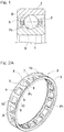
- Fig. 8 is a cross-sectional view of an angular contact ball bearing in which a conventional ball bearing retainer is used.
- Fig. 9 is a perspective view of the ball bearing retainer.
- Fig. 10 is a plan view as viewed from the outer diameter side of the ball bearing retainer.
- a conventional inner diameter restriction type rolling element guide retainer 30 has pockets Pt opened, each of pockets Pt is round as viewed from the radially outer side. That is, each pocket Pt has almost a cylindrical shape.
- Fig. 11 is a cross-sectional view taken along a line XI-XI in Fig. 8 .
- a gap "B" is formed when the retainer is positioned in a neutral position. Therefore, even if the retainer 30 is moved in the radial direction, ball guide is maintained so as to prevent the contact with an inner ring 33 and an outer ring 34.
- the ball 32 and the pocket Pt may come into contact with each other at points Q in the circumferential direction of the ball revolution, due to expansion of the retainer 30 by a centrifugal force, whirling or run-out thereof, or the like, and the ball 32 may strongly engage with the pocket Pt of the retainer 30. As a result, resistance or heat generation due to contact between the ball 32 and the pocket Pt may be increased.
- An object of the present invention is to provide a ball bearing retainer that allows high-speed operation while the ball bearing retainer is guided by balls.
- a ball bearing retainer of the present invention is directed to a ball guide retainer for a ball bearing which bearing includes: an inner ring; an outer ring; and balls interposed between the inner ring and the outer ring.
- the retainer includes an annular body formed with pockets at a plurality of portions thereof in a circumferential direction, the pockets holding the respective balls, in which case: the annular body includes annular parts and pillar parts, the annular parts being disposed on both sides in an axial direction, the pillar parts being disposed at a plurality of portions spaced in the circumferential direction and connecting between the annular parts; and the pockets are formed by the annular parts on both the sides in the axial direction and the pillar parts adjacent to each other in the circumferential direction.
- First contact portions of the pillar portions which contact portions contact with the balls in the circumferential direction, are formed by first planes that extend along the axial direction, and the balls are guided by the first planes.
- a first contact portion of each pillar part, which contact portion contacts with the ball in the circumferential direction, is formed by the first plane that extends along the axial direction.
- a contact area which contacts with the ball can be reduced as compared to a round hole contact portion of a conventional inner diameter restriction type rolling element guide retainer. Therefore, heat generation that occurs partially at the first contact portion can be reduced. Accordingly, in the ball bearing retainer of the present invention, even when a centrifugal force acts in high-speed operation, heat generation at the ball and the first contact portion can be reduced, and high speed operation can be thus performed. Further, since ball guide is performed, the inner diameter surface of the outer ring and the outer diameter surface of the inner ring need not be finished by grinding, whereby the number of steps for processing can be reduced.
- Second contact portions of the annular parts which contact portions contact with the balls in the axial direction, may be formed by second planes that extend along the circumferential direction, and the balls may be guided by the second planes.
- a load due to contact between the ball and the pocket can be separated into a load that acts in the bearing rotation direction and a load that acts in the axial direction. Therefore, a contact area which contacts with the ball can be reduced as compared to a conventional inner diameter restriction type retainer, and heat generation that occurs partially at the contact portion can be reduced.
- Connection regions that connect between the pillar parts and the annular parts may have each a roundly-chamfered R-shape or an arc-shape.
- spaces for lubrication are formed between the ball and the connection regions having the R-shape or the arc-shape.
- air oil lubrication by the "spaces" being formed, oil can be smoothly supplied and discharged, and an appropriate amount of oil is constantly supplied to the contact portion between the ball and the retainer pocket.
- the "spaces" contribute to holding of grease in the vicinity of the contact portion, and the grease held in the "spaces” is supplied to the ball and the retainer pocket. As a result, lubrication reliability in a high speed operation is enhanced, and friction and wear due to contact are reduced.
- Connection regions that connect between the pillar parts and the annular parts may have each an arc-shape, arc-shaped regions of the connection regions may have each an arc-shaped surface obtained by an arc center being offset from a center of a corresponding one of the pockets, and a gap may be formed between the arc-shaped surface and each ball.
- a gap for lubrication is formed between each arc-shaped connection region and the ball.
- air oil lubrication by the "gap" being formed, oil can be smoothly supplied and discharged, and an appropriate amount of oil is constantly supplied to the contact portion between the ball and the retainer pocket.
- the "gap" contributes to holding of grease in the vicinity of the contact portion, and the grease held in the "gap” is supplied to the ball and the retainer pocket. As a result, lubrication reliability in a high speed operation is enhanced, and friction and wear due to contact are reduced.
- a radius of each connection region may be greater than or equal to 15% of a total width, in the axial direction, of each pocket.
- the radius of each connection region is determined, for example, based on a result of a test, simulation or the like. When the radius of the connection region is limited to the above numerical values, lubrication reliability in a high speed operation can be further enhanced.
- the ball bearing retainer of the present invention may be tailored to be used for an angular contact ball bearing or may be made of a resin.
- the ball bearing retainer made of a resin may be an injection molding product. In this case, as compared to production of retainers by machining, excellent mass productivity is obtained and cost can be reduced.
- the annular body may include two annular segments that confront each other in the axial direction of the annular body, and the pockets may be formed by the annular segments being combined so as to confront each other in the axial direction.
- a plurality of balls are inserted between raceway surfaces of the inner ring and the outer ring, and thereafter the two annular segments are combined from both sides in the axial direction, whereby the retainer can be easily assembled.
- the retainer is made of a resin and the two annular segments have the same shape, the two annular segments can be formed by using one kind of forming mold. Accordingly, cost for the mold and cost for the retainer can be thus reduced. Further, the two annular segments to be combined need not be separately handled, and as a result, the annular segments can be easily managed.
- a ball bearing of the present invention may be an angular contact ball bearing, for a spindle of a machine tool, which includes the retainer of the present invention.
- FIG. 1 is a cross-sectional view of an angular contact ball bearing using the ball bearing retainer.
- the angular contact ball bearing includes: an inner ring 1; an outer ring 2; balls 4 interposed between the inner ring 1 and the outer ring 2; and a retainer 3 for retaining the balls 4.
- the retainer 3 is an inner diameter restriction type ball guide retainer.
- the balls 4 are formed as, for example, steel balls or ceramic balls.
- the retainer 3 includes an annular body 5 having therein pockets Pt formed at a plurality of portions along the circumferential direction thereof, and retains the balls 4, which are disposed between the inner ring 1 and the outer ring 2, in the pockets Pt.
- the retainer 3 is made of, for example, a resin, and is produced by injection molding.
- a resin material used for the retainer 3 a super engineering plastic, typified by a highly rigid PEEK resin that is advantageous in high speed rotation, which contains 20 to 40% of carbon fibers or glass fibers, or an engineering plastic, typified by a cost-friendly polyamide resin, which contains 20 to 40% of carbon fibers or glass fibers, can be used.
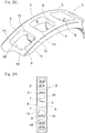
- Fig. 2A is a perspective view of the retainer 3, and Fig. 2B is an enlarged view of a main portion in Fig. 2A .
- Fig. 3A is a plan view of the retainer 3 as viewed from the outer diameter side, and Fig. 3B is an enlarged view of a main portion in Fig. 3A .
- the annular body 5 of the retainer 3 has: annular parts 6, 6 disposed on both sides in the axial direction; and pillar parts 7 disposed at a plurality of portions spaced in the circumferential direction so as to connect between the annular parts 6 and 6.
- Each pocket Pt is formed by the annular parts 6, 6, on both the sides in the axial direction, and the pillar parts 7, 7 adjacent to each other in the circumferential direction.
- each pocket Pt is formed in a substantially rectangular shape in a planar view when the retainer 3 is viewed from the outer diameter side.
- a pair of the pillar parts 7, 7 are disposed so as to confront each other in the circumferential direction.
- First contact portions in the pillar parts 7, which contact with the ball 4 ( Fig. 1 ) are formed by first planes 8 that extend along the axial direction.
- the ball 4 ( Fig. 1 ) is guided by the first planes 8.
- the first plane 8 of each pillar part 7 is referred to as a "rotation direction straight plane 8".
- the two rotation direction straight planes 8, 8 in each pocket Pt extend radially inward from portions adjacent to the mid-positions of the respective pillar parts 7 in the thickness direction, over a predetermined distance, such that the distance between the first planes 8, 8 in the circumferential direction is gradually reduced toward the distal ends thereof.
- Each rotation direction straight plane 8 has a width (dimension in the axial direction) that is reduced from the proximal end thereof toward the distal end thereof.
- the retainer 3 is formed as a ball guide inner diameter restriction type retainer by the rotation direction straight planes 8 in the pillar parts 7.
- Second contact portions of the annular parts 6 in the axial direction are formed by second planes 9 that extend along the circumferential direction.
- the ball 4 ( Fig. 1 ) is guided also by the second planes 9.
- Each second plane 9 of the annular part 6 is referred to as an "axial direction straight plane 9".
- the two axial direction straight planes 9, 9 are formed parallel to each other.
- the ball 4 ( Fig. 1 ) is guided by the rotation direction straight planes 8 and the axial direction straight planes 9. Therefore, a load due to contact between the ball 4 ( Fig. 1 ) and the pocket Pt can be separated into a load that acts in the bearing rotation direction and a load that acts in the axial direction.
- Connection regions 10 that connect between the pillar parts 7 and the annular parts 6 are each formed into a roundly-chamfered R-shape or arc-shape.
- the arc center of the R shape or the arc shape is positioned in the pocket Pt.
- the connection regions 10 are formed at four corners, respectively, of each pocket Pt that is shaped into a substantially rectangular shape.
- the radius of each connection region 10 is greater than or equal to 15% of the total width L1, in the axial direction, of the pocket Pt.
- the radius of each connection region 10 is determined, for example, according to a result of a test, simulation or the like.
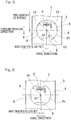
- Fig. 4 illustrates comparison between the retainer 3 (on the right side in Fig. 4 ) of the present embodiment and a conventional retainer 50 (on the left side in Fig. 4 ).
- the ball 4 contacts with a round hole surface 51 of a pocket Pt
- the retainer 3 of the present embodiment contacts with the rotation direction straight planes 8 of the pocket Pt.
- spaces 11 for lubrication are formed between the ball 4 and the connection regions 10 having the R-shape or the arc-shape.
- air oil lubrication by the spaces 11 being formed, oil can be smoothly supplied and discharged, and an appropriate amount of oil is constantly supplied to the contact portion between the ball 4 and the retainer pocket Pt.
- the spaces 11 contribute to holding of grease in the vicinity of the contact portion, and the grease held in the spaces 11 is supplied to the ball 4 and the retainer pocket Pt. As a result, lubrication reliability in a high speed operation is enhanced, and friction and wear due to contact are reduced.
- a first contact portion of each pillar part 7, which contacts with the ball 4 in the circumferential direction is formed by the first plane 8 that extends along the axial direction.
- a contact area which contacts with the ball 4 can be reduced as compared to a round hole contact portion of a conventional inner diameter restriction type rolling element guide retainer.
- heat generation that occurs partially at the contact portion can be reduced. Therefore, in the ball bearing retainer 3 of the present embodiment, even when a centrifugal force acts in high-speed operation, heat generation at the ball 4 and the first contact portion can be reduced, and high speed operation can be performed. Further, since ball guide is performed, the inner diameter surface of the outer ring and the outer diameter surface of the inner ring need not be finished by grinding, whereby the number of steps for processing can be reduced.
- each annular part 6, which contacts with the ball 4 in the axial direction is formed by the second plane 9 that extends along the circumferential direction, and the ball 4 is guided by the second plane 9.
- the ball 4 is guided by the first planes 8 of the pillar parts 7 and the second planes 9 of the annular parts 6, and therefore, a load due to contact between the ball 4 and the pocket Pt can be separated into a load that acts in the bearing rotation direction and a load that acts in the axial direction. Accordingly, a contact area which contacts with the ball can be reduced as compared to a conventional inner diameter restriction type retainer, and heat generation that occurs partially at the contact portion can be reduced.
- connection regions 10 that connect between the pillar parts 7 and the annular parts 6 are each arc-shaped.
- the arc-shaped portion of each connection region 10 is formed by an arc-shaped surface obtained by the arc center being offset from the center O1 of the pocket Pt in the axial direction and the circumferential direction.
- a gap is formed between each arc-shaped surface and the ball.
- arc-shaped portions of connection regions 10 are each formed by an arc-shaped surface obtained by the arc center being offset from the center O1 of the pocket Pt in the axial direction.
- a gap is formed between each arc-shaped surface and the ball.
- gaps for lubrication are formed between the arc-shaped connection regions 10 and the ball.
- air oil lubrication by the "gaps" being formed, oil can be smoothly supplied and discharged, and an appropriate amount of oil is constantly supplied to the contact portion between the ball and the retainer pocket Pt.
- the gaps contribute to holding of grease in the vicinity of the contact portion, and the grease held in the gaps is supplied to the ball and the retainer pocket Pt. As a result, lubrication reliability in a high speed operation is enhanced, and friction and wear due to contact are reduced.
- an annular body 5 of a retainer 3A has two divisional annular segments 12, 12 that can be divided in the axial direction.
- the two annular segments 12, 12 are combined, thereby forming the retainer 3A having a plurality of pockets Pt.
- the two annular segments 12, 12 have the same shape, and are combined with each other while being disposed oppositely in the axial direction.
- each pillar part 7 has an engagement surface 13 at which the two annular segments 12, 12 come into surface contact with each other when combined.
- the engagement surface 13 is formed by a plane that is perpendicular to the axial direction except for a portion adjacent to the center portion, in the circumferential direction, of each pillar part 7.
- the engagement surface 13 is formed at a position that axially deviates from the center, in the axial direction, of the annular body 5.
- the two divisional annular segments 12, 12 that can be divided in the axial direction are combined so as to confront each other in the axial direction, whereby the annular body 5 having a plurality of pockets Pt is formed. Therefore, a plurality of balls 4 ( Fig. 1 ) are inserted between raceway surfaces of the inner ring 1 and the outer ring 2 ( Fig. 1 ), and thereafter the two annular segments 12, 12 are combined from both sides in the axial direction, whereby the retainer 3A can be easily assembled.
- the retainer 3A is made of a resin, and the two annular segments 12, 12 have the same shape. Therefore, the two annular segments 12, 12 can be formed by using one kind of forming mold. Accordingly, cost for the mold and cost for the retainer 3A can be thus reduced. Further, the two annular segments 12, 12 to be combined need not be separately handled and the annular segments 12 can be easily managed.
Abstract
Description
- This application is based on and claims Convention priority to Japanese patent application No.
2014-199923, filed September 30, 2014 2015-012108, filed January 26, 2015 - The present invention relates to ball bearing retainers or cages used for, for example, spindles of machine tools.
- An angular contact ball bearing used for a spindle of a machine tool is rotated at a high speed. Therefore, a metallic retainer having a high specific gravity is rarely used, and a retainer made of a resin, such as nylon polyamide, PPS (Poly Phenylene Sulfide Resin), PEEK (Poly Ether Ether Ketone), or phenolic resin, which is reinforced by glass fibers, carbon fibers, or the like is used.
- In general, an inner diameter restriction type rolling element guide retainer is used in intermediate and low speed ranges in many cases (for example,
Patent Documents 1 to 3 listed below).Patent Documents Patent Document 3 discloses an inner diameter restriction type ball guide retainer. Further, an outer diameter restriction type roller guide retainer is also suggested (Patent Document 4). The rolling element guide retainer is guided by (in contact with) balls which have been quality-controlled to have fine surface roughness with high accuracy, and the inner diameter surface of an outer ring and the outer diameter surface of an inner ring do not need to be finished by grinding, as distinct from an inner ring guide retainer and an outer ring guide retainer. Therefore, a rolling element guide retainer is excellent in cost as compared to an inner ring guide retainer and an outer ring guide retainer. -
- [Patent Document 1]
-
JP Patent No. 3611918 - [Patent Document 2]
-
JP Laid-open Patent Publication No. H09-236127 - [Patent Document 3]
-
JP Patent No. 4192515 - [Patent Document 4]
-
JP Laid-open Patent Publication No. 2006-161882 - However, in a high speed range in which, for example, a dmn value that is a product of the rolling element center diameter dm (mm) and a rotation speed n (min-1) exceeds one million, a rolling element guide retainer expands due to action of a centrifugal force, and a ball (rolling element) and a ball receiver portion (inner diameter side portion of the retainer in the case of an inner diameter restriction type) of the retainer come into hard contact with each other during the guiding in the radial direction. Therefore, resistance or heat generation at the ball receiver portion gradually increases, thereby developing into insufficient lubrication, and, in a worst case, into an abnormal wear or melting at the contact surface.
-
Fig. 8 is a cross-sectional view of an angular contact ball bearing in which a conventional ball bearing retainer is used.Fig. 9 is a perspective view of the ball bearing retainer.Fig. 10 is a plan view as viewed from the outer diameter side of the ball bearing retainer. As shown inFig. 8 to Fig. 10 , a conventional inner diameter restriction type rollingelement guide retainer 30 has pockets Pt opened, each of pockets Pt is round as viewed from the radially outer side. That is, each pocket Pt has almost a cylindrical shape.Fig. 11 is a cross-sectional view taken along a line XI-XI inFig. 8 . Between an inner diameter restriction typeball receiver portion 31 and aball 32, a gap "B" is formed when the retainer is positioned in a neutral position. Therefore, even if theretainer 30 is moved in the radial direction, ball guide is maintained so as to prevent the contact with aninner ring 33 and anouter ring 34. - If a bearing having the inner diameter restriction type rolling
element guide retainer 30 is rotated at a high speed, theball 32 and the pocket Pt may come into contact with each other at points Q in the circumferential direction of the ball revolution, due to expansion of theretainer 30 by a centrifugal force, whirling or run-out thereof, or the like, and theball 32 may strongly engage with the pocket Pt of theretainer 30. As a result, resistance or heat generation due to contact between theball 32 and the pocket Pt may be increased. - An object of the present invention is to provide a ball bearing retainer that allows high-speed operation while the ball bearing retainer is guided by balls.
- A ball bearing retainer of the present invention is directed to a ball guide retainer for a ball bearing which bearing includes: an inner ring; an outer ring; and balls interposed between the inner ring and the outer ring. The retainer includes an annular body formed with pockets at a plurality of portions thereof in a circumferential direction, the pockets holding the respective balls, in which case: the annular body includes annular parts and pillar parts, the annular parts being disposed on both sides in an axial direction, the pillar parts being disposed at a plurality of portions spaced in the circumferential direction and connecting between the annular parts; and the pockets are formed by the annular parts on both the sides in the axial direction and the pillar parts adjacent to each other in the circumferential direction. First contact portions of the pillar portions, which contact portions contact with the balls in the circumferential direction, are formed by first planes that extend along the axial direction, and the balls are guided by the first planes.
- In this configuration, a first contact portion of each pillar part, which contact portion contacts with the ball in the circumferential direction, is formed by the first plane that extends along the axial direction. Thus, a contact area which contacts with the ball can be reduced as compared to a round hole contact portion of a conventional inner diameter restriction type rolling element guide retainer. Therefore, heat generation that occurs partially at the first contact portion can be reduced. Accordingly, in the ball bearing retainer of the present invention, even when a centrifugal force acts in high-speed operation, heat generation at the ball and the first contact portion can be reduced, and high speed operation can be thus performed. Further, since ball guide is performed, the inner diameter surface of the outer ring and the outer diameter surface of the inner ring need not be finished by grinding, whereby the number of steps for processing can be reduced.
- Second contact portions of the annular parts, which contact portions contact with the balls in the axial direction, may be formed by second planes that extend along the circumferential direction, and the balls may be guided by the second planes. In this case, since the ball is guided by the first planes of the pillar parts and the second planes of the annular parts, a load due to contact between the ball and the pocket can be separated into a load that acts in the bearing rotation direction and a load that acts in the axial direction. Therefore, a contact area which contacts with the ball can be reduced as compared to a conventional inner diameter restriction type retainer, and heat generation that occurs partially at the contact portion can be reduced.
- Connection regions that connect between the pillar parts and the annular parts may have each a roundly-chamfered R-shape or an arc-shape. In this case, spaces for lubrication are formed between the ball and the connection regions having the R-shape or the arc-shape. In the case of air oil lubrication, by the "spaces" being formed, oil can be smoothly supplied and discharged, and an appropriate amount of oil is constantly supplied to the contact portion between the ball and the retainer pocket. In the case of grease lubrication, the "spaces" contribute to holding of grease in the vicinity of the contact portion, and the grease held in the "spaces" is supplied to the ball and the retainer pocket. As a result, lubrication reliability in a high speed operation is enhanced, and friction and wear due to contact are reduced.
- Connection regions that connect between the pillar parts and the annular parts may have each an arc-shape, arc-shaped regions of the connection regions may have each an arc-shaped surface obtained by an arc center being offset from a center of a corresponding one of the pockets, and a gap may be formed between the arc-shaped surface and each ball. In this case, a gap for lubrication is formed between each arc-shaped connection region and the ball. In the case of air oil lubrication, by the "gap" being formed, oil can be smoothly supplied and discharged, and an appropriate amount of oil is constantly supplied to the contact portion between the ball and the retainer pocket. In the case of grease lubrication, the "gap" contributes to holding of grease in the vicinity of the contact portion, and the grease held in the "gap" is supplied to the ball and the retainer pocket. As a result, lubrication reliability in a high speed operation is enhanced, and friction and wear due to contact are reduced.
- A radius of each connection region may be greater than or equal to 15% of a total width, in the axial direction, of each pocket. The radius of each connection region is determined, for example, based on a result of a test, simulation or the like. When the radius of the connection region is limited to the above numerical values, lubrication reliability in a high speed operation can be further enhanced.
- The ball bearing retainer of the present invention may be tailored to be used for an angular contact ball bearing or may be made of a resin. The ball bearing retainer made of a resin may be an injection molding product. In this case, as compared to production of retainers by machining, excellent mass productivity is obtained and cost can be reduced.
- The annular body may include two annular segments that confront each other in the axial direction of the annular body, and the pockets may be formed by the annular segments being combined so as to confront each other in the axial direction. In this case, a plurality of balls are inserted between raceway surfaces of the inner ring and the outer ring, and thereafter the two annular segments are combined from both sides in the axial direction, whereby the retainer can be easily assembled. When the retainer is made of a resin and the two annular segments have the same shape, the two annular segments can be formed by using one kind of forming mold. Accordingly, cost for the mold and cost for the retainer can be thus reduced. Further, the two annular segments to be combined need not be separately handled, and as a result, the annular segments can be easily managed.
- A ball bearing of the present invention may be an angular contact ball bearing, for a spindle of a machine tool, which includes the retainer of the present invention.
- Any combination of at least two constructions, disclosed in the appended claims and/or the specification and/or the accompanying drawings should be construed as included within the scope of the present invention. In particular, any combination of two or more of the appended claims should be equally construed as included within the scope of the present invention.
- In any event, the present invention will become more clearly understood from the following description of preferred embodiments thereof, when taken in conjunction with the accompanying drawings. However, the embodiments and the drawings are given only for the purpose of illustration and explanation, and are not to be taken as limiting the scope of the present invention in any way whatsoever, which scope is to be determined by the appended claims. In the accompanying drawings, like reference numerals are used to denote like parts throughout the several views, and:
-
Fig. 1 is a cross-sectional view of an angular contact ball bearing using a ball bearing retainer according to a first embodiment of the present invention; -
Fig. 2A is a perspective view of the ball bearing retainer; -
Fig. 2B is an enlarged view of a main portion inFig. 2A ; -
Fig. 3A is a plan view of the ball bearing retainer as viewed from the outer diameter side; -
Fig. 3B is an enlarged view of a main portion inFig. 3A ; -
Fig. 4 illustrates comparison between the ball bearing retainer and a conventional retainer; -
Fig. 5 is an enlarged plan view of a main portion of a ball bearing retainer, as viewed from the outer diameter side, according to a second embodiment of the present invention; -
Fig. 6 is an enlarged plan view of a main portion of a ball bearing retainer, as viewed from the outer diameter side, according to a third embodiment of the present invention; -
Fig. 7 is a plan view of a main portion of a ball bearing retainer, as viewed from the outer diameter side, according to a fourth embodiment of the present invention; -
Fig. 8 is a cross-sectional view of an angular contact ball bearing using a conventional ball bearing retainer; -
Fig. 9 is a perspective view of the ball bearing retainer; -
Fig. 10 is a plan view of the ball bearing retainer as viewed from the outer diameter side; and -
Fig. 11 is a cross-sectional view taken along a line XI-XI inFig. 8 . - A first embodiment of the present invention will be described with reference to
Fig. 1 to Fig. 4 . A ball bearing retainer or cage according to the present embodiment is applied particularly to a retainer of an angular contact ball bearing for a spindle of a machine tool.Fig. 1 is a cross-sectional view of an angular contact ball bearing using the ball bearing retainer. The angular contact ball bearing includes: aninner ring 1; anouter ring 2;balls 4 interposed between theinner ring 1 and theouter ring 2; and aretainer 3 for retaining theballs 4. Theretainer 3 is an inner diameter restriction type ball guide retainer. Theballs 4 are formed as, for example, steel balls or ceramic balls. - The
retainer 3 includes anannular body 5 having therein pockets Pt formed at a plurality of portions along the circumferential direction thereof, and retains theballs 4, which are disposed between theinner ring 1 and theouter ring 2, in the pockets Pt. Theretainer 3 is made of, for example, a resin, and is produced by injection molding. As a resin material used for theretainer 3, a super engineering plastic, typified by a highly rigid PEEK resin that is advantageous in high speed rotation, which contains 20 to 40% of carbon fibers or glass fibers, or an engineering plastic, typified by a cost-friendly polyamide resin, which contains 20 to 40% of carbon fibers or glass fibers, can be used. -
Fig. 2A is a perspective view of theretainer 3, andFig. 2B is an enlarged view of a main portion inFig. 2A .Fig. 3A is a plan view of theretainer 3 as viewed from the outer diameter side, andFig. 3B is an enlarged view of a main portion inFig. 3A . As shown inFig. 2A to Fig. 3B , theannular body 5 of theretainer 3 has:annular parts pillar parts 7 disposed at a plurality of portions spaced in the circumferential direction so as to connect between theannular parts annular parts pillar parts - As shown in
Fig. 2B andFig. 3B , each pocket Pt is formed in a substantially rectangular shape in a planar view when theretainer 3 is viewed from the outer diameter side. In each pocket Pt, a pair of thepillar parts pillar parts 7, which contact with the ball 4 (Fig. 1 ), are formed byfirst planes 8 that extend along the axial direction. The ball 4 (Fig. 1 ) is guided by thefirst planes 8. Thefirst plane 8 of eachpillar part 7 is referred to as a "rotation directionstraight plane 8". - The two rotation direction
straight planes respective pillar parts 7 in the thickness direction, over a predetermined distance, such that the distance between thefirst planes straight plane 8 has a width (dimension in the axial direction) that is reduced from the proximal end thereof toward the distal end thereof. Theretainer 3 is formed as a ball guide inner diameter restriction type retainer by the rotation directionstraight planes 8 in thepillar parts 7. - Second contact portions of the
annular parts 6 in the axial direction are formed bysecond planes 9 that extend along the circumferential direction. The ball 4 (Fig. 1 ) is guided also by the second planes 9. Eachsecond plane 9 of theannular part 6 is referred to as an "axial directionstraight plane 9". In each pocket Pt, the two axial directionstraight planes Fig. 1 ) is guided by the rotation directionstraight planes 8 and the axial direction straight planes 9. Therefore, a load due to contact between the ball 4 (Fig. 1 ) and the pocket Pt can be separated into a load that acts in the bearing rotation direction and a load that acts in the axial direction. -
Connection regions 10 that connect between thepillar parts 7 and theannular parts 6 are each formed into a roundly-chamfered R-shape or arc-shape. The arc center of the R shape or the arc shape is positioned in the pocket Pt. Theconnection regions 10 are formed at four corners, respectively, of each pocket Pt that is shaped into a substantially rectangular shape. The radius of eachconnection region 10 is greater than or equal to 15% of the total width L1, in the axial direction, of the pocket Pt. The radius of eachconnection region 10 is determined, for example, according to a result of a test, simulation or the like. -
Fig. 4 illustrates comparison between the retainer 3 (on the right side inFig. 4 ) of the present embodiment and a conventional retainer 50 (on the left side inFig. 4 ). In theconventional retainer 50 theball 4 contacts with around hole surface 51 of a pocket Pt, whereas in theretainer 3 of the present embodiment theball 4 contacts with the rotation directionstraight planes 8 of the pocket Pt. - Further, in the
retainer 3 of the present embodiment,spaces 11 for lubrication are formed between theball 4 and theconnection regions 10 having the R-shape or the arc-shape. In the case of air oil lubrication, by thespaces 11 being formed, oil can be smoothly supplied and discharged, and an appropriate amount of oil is constantly supplied to the contact portion between theball 4 and the retainer pocket Pt. In the case of grease lubrication, thespaces 11 contribute to holding of grease in the vicinity of the contact portion, and the grease held in thespaces 11 is supplied to theball 4 and the retainer pocket Pt. As a result, lubrication reliability in a high speed operation is enhanced, and friction and wear due to contact are reduced. - In the
retainer 3 described above, a first contact portion of eachpillar part 7, which contacts with theball 4 in the circumferential direction, is formed by thefirst plane 8 that extends along the axial direction. Thus, a contact area which contacts with theball 4 can be reduced as compared to a round hole contact portion of a conventional inner diameter restriction type rolling element guide retainer. As a result, heat generation that occurs partially at the contact portion can be reduced. Therefore, in theball bearing retainer 3 of the present embodiment, even when a centrifugal force acts in high-speed operation, heat generation at theball 4 and the first contact portion can be reduced, and high speed operation can be performed. Further, since ball guide is performed, the inner diameter surface of the outer ring and the outer diameter surface of the inner ring need not be finished by grinding, whereby the number of steps for processing can be reduced. - The second contact portion of each
annular part 6, which contacts with theball 4 in the axial direction, is formed by thesecond plane 9 that extends along the circumferential direction, and theball 4 is guided by thesecond plane 9. Theball 4 is guided by thefirst planes 8 of thepillar parts 7 and thesecond planes 9 of theannular parts 6, and therefore, a load due to contact between theball 4 and the pocket Pt can be separated into a load that acts in the bearing rotation direction and a load that acts in the axial direction. Accordingly, a contact area which contacts with the ball can be reduced as compared to a conventional inner diameter restriction type retainer, and heat generation that occurs partially at the contact portion can be reduced. - Other embodiments will be described.
- In the following description, components corresponding to the matters described in the embodiment preceding each embodiment are denoted by like reference numerals, and description thereof is not repeated. In a case where only a portion of the configuration is described, the other portions of the configuration are the same as described in the preceding embodiments, unless otherwise specified. The same function and effect can be obtained from the same configuration. Not only portions that are specifically described in the embodiments may be combined, but also the embodiments may be partially combined unless any problem arises in the combination.
- In a second embodiment shown in
Fig. 5 ,connection regions 10 that connect between thepillar parts 7 and theannular parts 6 are each arc-shaped. The arc-shaped portion of eachconnection region 10 is formed by an arc-shaped surface obtained by the arc center being offset from the center O1 of the pocket Pt in the axial direction and the circumferential direction. A gap is formed between each arc-shaped surface and the ball. - In a third embodiment shown in
Fig. 6 , arc-shaped portions ofconnection regions 10 are each formed by an arc-shaped surface obtained by the arc center being offset from the center O1 of the pocket Pt in the axial direction. A gap is formed between each arc-shaped surface and the ball. - In the second and the third embodiments, gaps for lubrication are formed between the arc-shaped
connection regions 10 and the ball. In the case of air oil lubrication, by the "gaps" being formed, oil can be smoothly supplied and discharged, and an appropriate amount of oil is constantly supplied to the contact portion between the ball and the retainer pocket Pt. In the case of grease lubrication, the gaps contribute to holding of grease in the vicinity of the contact portion, and the grease held in the gaps is supplied to the ball and the retainer pocket Pt. As a result, lubrication reliability in a high speed operation is enhanced, and friction and wear due to contact are reduced. - In a fourth embodiment shown in
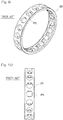
Fig. 7 , anannular body 5 of aretainer 3A has two divisionalannular segments annular segments retainer 3A having a plurality of pockets Pt. In the fourth embodiment, the twoannular segments pillar part 7 has anengagement surface 13 at which the twoannular segments engagement surface 13 is formed by a plane that is perpendicular to the axial direction except for a portion adjacent to the center portion, in the circumferential direction, of eachpillar part 7. Theengagement surface 13 is formed at a position that axially deviates from the center, in the axial direction, of theannular body 5. - In the
retainer 3A of the fourth embodiment, the two divisionalannular segments annular body 5 having a plurality of pockets Pt is formed. Therefore, a plurality of balls 4 (Fig. 1 ) are inserted between raceway surfaces of theinner ring 1 and the outer ring 2 (Fig. 1 ), and thereafter the twoannular segments retainer 3A can be easily assembled. - The
retainer 3A is made of a resin, and the twoannular segments annular segments retainer 3A can be thus reduced. Further, the twoannular segments annular segments 12 can be easily managed. - The present invention has been fully described in connection with the embodiments. However, the embodiments disclosed herein are in all aspects illustrative and not restrictive. The scope of the present invention is to be determined not by the above explanation but by the appended claims, and includes equivalents of the claims and all modifications within the scope of the present invention.
-
- 1 .... inner ring
- 2 .... outer ring
- 3, 3A .... retainer
- 4 .... ball
- 5 .... annular body
- 6 .... annular part
- 7 .... pillar part
- 8 .... rotation direction straight plane (first plane)
- 9 .... axial direction straight plane (second plane)
- 10 .... connection region
- 12 .... annular segment
- Pt .... pocket
Claims (10)
- A ball guide retainer for a ball bearing which bearing includes: an inner ring; and an outer ring; and balls interposed between the inner ring and the outer ring, the retainer comprising
an annular body formed with pockets at a plurality of portions thereof in a circumferential direction, the pockets holding the respective balls, wherein
the annular body includes annular parts and pillar parts, the annular parts being disposed on both sides in an axial direction, the pillar parts being disposed at a plurality of portions spaced in the circumferential direction and connecting between the annular parts,
the pockets are formed by the annular parts on both the sides in the axial direction and the pillar parts adjacent to each other in the circumferential direction, and
first contact portions of the pillar portions, which contact portions contact with the balls in the circumferential direction, are formed by first planes that extend along the axial direction, and the balls are guided by the first planes. - The retainer for the ball bearing as claimed in claim 1, wherein, second contact portions of the annular parts, which contact portions contact with the balls in the axial direction, are formed by second planes that extend along the circumferential direction, and the balls are guided by the second planes.
- The retainer for the ball bearing as claimed in claim 2, wherein connection regions that connect between the pillar parts and the annular parts have each a roundly-chamfered R-shape or an arc-shape.
- The retainer for the ball bearing as claimed in claim 2, wherein
connection regions that connect between the pillar parts and the annular parts have each an arc-shape,
arc-shaped regions of the connection regions have each an arc-shaped surface obtained by an arc center being offset from a center of a corresponding one of the pockets, and
a gap is formed between the arc-shaped surface and each ball. - The retainer for the ball bearing as claimed in claim 3 or 4, wherein a radius of each connection region is greater than or equal to 15% of a total width, in the axial direction, of each pocket.
- The retainer for the ball bearing as claimed in any one of claims 1 to 5, which retainer is tailored to be used for an angular contact ball bearing.
- The retainer for the ball bearing as claimed in any one of claims 1 to 6, which retainer is made of a resin.
- The retainer for the ball bearing as claimed in claim 7, which retainer is an injection molding product.
- The retainer for the ball bearing as claimed in any one of claims 1 to 8, wherein
the annular body includes two annular segments that confront each other in the axial direction of the annular body, and
the pockets are formed by the annular segments being combined so as to confront each other in the axial direction. - An angular contact ball bearing for a spindle of a machine tool, which ball bearing comprises the retainer as claimed in any one of claims 1 to 9.
Applications Claiming Priority (3)
| Application Number | Priority Date | Filing Date | Title |
|---|---|---|---|
| JP2014199923 | 2014-09-30 | ||
| JP2015012108A JP6556454B2 (en) | 2014-09-30 | 2015-01-26 | Ball bearing cage |
| PCT/JP2015/076505 WO2016052232A1 (en) | 2014-09-30 | 2015-09-17 | Ball bearing cage |
Publications (3)
| Publication Number | Publication Date |
|---|---|
| EP3203099A1 true EP3203099A1 (en) | 2017-08-09 |
| EP3203099A4 EP3203099A4 (en) | 2018-06-20 |
| EP3203099B1 EP3203099B1 (en) | 2019-10-23 |
Family
ID=55864359
Family Applications (1)
| Application Number | Title | Priority Date | Filing Date |
|---|---|---|---|
| EP15847007.0A Active EP3203099B1 (en) | 2014-09-30 | 2015-09-17 | Ball bearing cage |
Country Status (6)
| Country | Link |
|---|---|
| US (1) | US10663001B2 (en) |
| EP (1) | EP3203099B1 (en) |
| JP (1) | JP6556454B2 (en) |
| KR (1) | KR102445802B1 (en) |
| CN (1) | CN107076206B (en) |
| TW (1) | TWI678478B (en) |
Families Citing this family (3)
| Publication number | Priority date | Publication date | Assignee | Title |
|---|---|---|---|---|
| DE102015224859A1 (en) * | 2015-12-10 | 2017-06-14 | Schaeffler Technologies AG & Co. KG | A ball bearing retainer |
| WO2019146768A1 (en) * | 2018-01-26 | 2019-08-01 | 日本精工株式会社 | Angular ball bearing |
| CN112013030B (en) * | 2020-08-20 | 2022-02-08 | 杭州康丰机械设备有限公司 | Industrial anti-skid bearing |
Family Cites Families (35)
| Publication number | Priority date | Publication date | Assignee | Title |
|---|---|---|---|---|
| US2327237A (en) * | 1940-01-20 | 1943-08-17 | Norma Hoffman Bearings Corp | Method for making retainers for antifriction bearings |
| US3588207A (en) * | 1970-01-15 | 1971-06-28 | Ind Tectonics Inc | Rolling element retainer having element retaining tabs |
| US3707753A (en) * | 1971-09-08 | 1973-01-02 | Trw Inc | Method of making cages |
| US3839531A (en) * | 1972-12-29 | 1974-10-01 | Textron Inc | Method for making a retaining ring for an antifriction bearing |
| JPS53135595A (en) | 1977-04-30 | 1978-11-27 | Toshiba Corp | Discharge unit |
| US4653938A (en) * | 1981-04-23 | 1987-03-31 | Rockwell International Corporation | Self-adjusting ball bearing cage |
| JPS5839817A (en) * | 1981-09-03 | 1983-03-08 | Nippon Seiko Kk | Manufacture of retainer for solid roller bearing |
| DE3247948C2 (en) | 1982-12-24 | 1985-10-17 | SKF GmbH, 8720 Schweinfurt | Cage for ball bearings, especially for angular contact ball bearings |
| JPS611918A (en) | 1984-06-13 | 1986-01-07 | Matsushita Electric Ind Co Ltd | Control device of combustion tool |
| JPS626532U (en) * | 1985-06-28 | 1987-01-16 | ||
| JP3611918B2 (en) | 1996-02-29 | 2005-01-19 | Ntn株式会社 | Resin cage for angular contact ball bearings |
| IT1293628B1 (en) * | 1997-07-18 | 1999-03-08 | Skf Ind Spa | ROLLING BODY CONTAINMENT CONTROL STRUCTURE OF A ROLLING BEARING, IN PARTICULAR OF A ROLLER BEARING |
| JP2001012477A (en) * | 1999-04-28 | 2001-01-16 | Nsk Ltd | Cage for rolling bearing |
| JP2002357226A (en) * | 2001-03-28 | 2002-12-13 | Nsk Ltd | Ball bearing |
| JP4192515B2 (en) | 2002-07-16 | 2008-12-10 | 株式会社ジェイテクト | Resin cage for angular contact ball bearings |
| JP2004316757A (en) * | 2003-04-15 | 2004-11-11 | Ntn Corp | Cylindrical roller bearing and retainer for cylindrical roller bearing |
| JP4383766B2 (en) * | 2003-04-18 | 2009-12-16 | Ntn株式会社 | Synthetic resin cages and angular contact ball bearings for angular contact ball bearings |
| JP2004324699A (en) * | 2003-04-22 | 2004-11-18 | Nsk Ltd | Roller bearing |
| US7931410B2 (en) * | 2004-10-22 | 2011-04-26 | Ntn Corporation | Machined cage for cylindrical roller bearing and method of manufacturing the same |
| JP2006161882A (en) | 2004-12-03 | 2006-06-22 | Ntn Corp | Rolling bearing cage |
| JP2007147010A (en) * | 2005-11-29 | 2007-06-14 | Ntn Corp | Ball bearing cage, ball bearing and machine tool |
| JP2008133894A (en) * | 2006-11-28 | 2008-06-12 | Ntn Corp | Ball bearing retainer |
| JP2009058039A (en) | 2007-08-31 | 2009-03-19 | Jtekt Corp | Cage for rolling bearing |
| TWM331056U (en) * | 2007-11-14 | 2008-04-21 | Tungpei Ind Co Ltd | Structure of retainer of ball bearing |
| DE102007057550A1 (en) * | 2007-11-29 | 2009-06-04 | Schaeffler Kg | Cage for a roller bearing and method for its production |
| WO2009150935A1 (en) * | 2008-06-13 | 2009-12-17 | Ntn株式会社 | Retainer, deep groove ball bearing, and bearing with seal |
| JP2011085153A (en) * | 2009-10-13 | 2011-04-28 | Toyota Motor Corp | Rolling bearing |
| DE102010038592B3 (en) * | 2010-07-29 | 2012-02-09 | Aktiebolaget Skf | Rolling bearing cage |
| JP5500014B2 (en) * | 2010-09-09 | 2014-05-21 | 株式会社ジェイテクト | Ball bearing cage and ball bearing |
| JP6370026B2 (en) * | 2011-11-29 | 2018-08-08 | 日本精工株式会社 | Cage and rolling bearing |
| JP5507640B2 (en) * | 2012-09-18 | 2014-05-28 | 凸版印刷株式会社 | Odor adsorbent, odor detection kit, and usage |
| JP2015048874A (en) * | 2013-08-30 | 2015-03-16 | Ntn株式会社 | Retainer for ball bearing |
| DE112016001671T5 (en) * | 2015-04-10 | 2018-01-04 | Ntn Corporation | Tapered roller bearings |
| JP2017057982A (en) * | 2015-09-18 | 2017-03-23 | Ntn株式会社 | Rolling ball bearing |
| DE102015224859A1 (en) * | 2015-12-10 | 2017-06-14 | Schaeffler Technologies AG & Co. KG | A ball bearing retainer |
-
2015
- 2015-01-26 JP JP2015012108A patent/JP6556454B2/en active Active
- 2015-09-17 KR KR1020177007617A patent/KR102445802B1/en active IP Right Grant
- 2015-09-17 CN CN201580052373.6A patent/CN107076206B/en active Active
- 2015-09-17 EP EP15847007.0A patent/EP3203099B1/en active Active
- 2015-09-25 TW TW104131689A patent/TWI678478B/en active
-
2017
- 2017-03-20 US US15/463,541 patent/US10663001B2/en active Active
Also Published As
| Publication number | Publication date |
|---|---|
| CN107076206A (en) | 2017-08-18 |
| TWI678478B (en) | 2019-12-01 |
| EP3203099A4 (en) | 2018-06-20 |
| KR102445802B1 (en) | 2022-09-20 |
| US20170191528A1 (en) | 2017-07-06 |
| JP6556454B2 (en) | 2019-08-07 |
| EP3203099B1 (en) | 2019-10-23 |
| JP2016070485A (en) | 2016-05-09 |
| CN107076206B (en) | 2021-01-15 |
| US10663001B2 (en) | 2020-05-26 |
| TW201632748A (en) | 2016-09-16 |
| KR20170063587A (en) | 2017-06-08 |
Similar Documents
| Publication | Publication Date | Title |
|---|---|---|
| US9995341B2 (en) | Resin cage for tapered roller bearing and tapered roller bearing including the resin cage | |
| US20160178007A1 (en) | Ball bearing retainer | |
| US20190368540A1 (en) | Rolling bearing cage and rolling bearing | |
| KR102018966B1 (en) | Rolling bearing retainer, rolling bearing, and method for manufacturing rolling bearing retainer | |
| US10663001B2 (en) | Ball bearing cage | |
| KR101960144B1 (en) | Angular ball bearing | |
| JP2019074214A (en) | Angular ball bearing and its manufacturing method | |
| JP4537920B2 (en) | Resin retainer, resin retainer mold and resin retainer manufacturing method | |
| JP2005201457A (en) | Cylindrical roller bearing | |
| KR101988706B1 (en) | Angular ball bearing | |
| JP6529209B2 (en) | Angular contact ball bearings | |
| KR20170015372A (en) | Crown cage and angular contact ball bearing | |
| JP6493580B2 (en) | Angular contact ball bearings | |
| WO2016052232A1 (en) | Ball bearing cage | |
| JP2007100909A (en) | Roller bearing | |
| CN106917824B (en) | Rolling bearing | |
| JP2009275722A (en) | Rolling bearing | |
| EP3540250A1 (en) | Resin holder for cylindrical roller bearings and cylindrical roller bearing | |
| JP2004019723A (en) | Method of manufacturing cylindrical roller bearing, and cylindrical roller bearing | |
| CN117321313A (en) | Rolling bearing cage | |
| JP2008008370A (en) | Cylindrical roller bearing cage | |
| JP2016161118A (en) | Conical roller bearing and holder used in the same | |
| JP2008019936A (en) | Ball bearing and retainer for ball bearing |
Legal Events
| Date | Code | Title | Description |
|---|---|---|---|
| STAA | Information on the status of an ep patent application or granted ep patent |
Free format text: STATUS: THE INTERNATIONAL PUBLICATION HAS BEEN MADE |
|
| PUAI | Public reference made under article 153(3) epc to a published international application that has entered the european phase |
Free format text: ORIGINAL CODE: 0009012 |
|
| STAA | Information on the status of an ep patent application or granted ep patent |
Free format text: STATUS: REQUEST FOR EXAMINATION WAS MADE |
|
| 17P | Request for examination filed |
Effective date: 20170413 |
|
| AK | Designated contracting states |
Kind code of ref document: A1 Designated state(s): AL AT BE BG CH CY CZ DE DK EE ES FI FR GB GR HR HU IE IS IT LI LT LU LV MC MK MT NL NO PL PT RO RS SE SI SK SM TR |
|
| AX | Request for extension of the european patent |
Extension state: BA ME |
|
| DAV | Request for validation of the european patent (deleted) | ||
| DAX | Request for extension of the european patent (deleted) | ||
| A4 | Supplementary search report drawn up and despatched |
Effective date: 20180524 |
|
| RIC1 | Information provided on ipc code assigned before grant |
Ipc: F16C 19/16 20060101ALI20180517BHEP Ipc: F16C 33/38 20060101AFI20180517BHEP Ipc: F16C 33/44 20060101ALI20180517BHEP |
|
| GRAP | Despatch of communication of intention to grant a patent |
Free format text: ORIGINAL CODE: EPIDOSNIGR1 |
|
| STAA | Information on the status of an ep patent application or granted ep patent |
Free format text: STATUS: GRANT OF PATENT IS INTENDED |
|
| INTG | Intention to grant announced |
Effective date: 20190507 |
|
| GRAS | Grant fee paid |
Free format text: ORIGINAL CODE: EPIDOSNIGR3 |
|
| GRAJ | Information related to disapproval of communication of intention to grant by the applicant or resumption of examination proceedings by the epo deleted |
Free format text: ORIGINAL CODE: EPIDOSDIGR1 |
|
| GRAL | Information related to payment of fee for publishing/printing deleted |
Free format text: ORIGINAL CODE: EPIDOSDIGR3 |
|
| STAA | Information on the status of an ep patent application or granted ep patent |
Free format text: STATUS: REQUEST FOR EXAMINATION WAS MADE |
|
| GRAR | Information related to intention to grant a patent recorded |
Free format text: ORIGINAL CODE: EPIDOSNIGR71 |
|
| STAA | Information on the status of an ep patent application or granted ep patent |
Free format text: STATUS: GRANT OF PATENT IS INTENDED |
|
| GRAA | (expected) grant |
Free format text: ORIGINAL CODE: 0009210 |
|
| STAA | Information on the status of an ep patent application or granted ep patent |
Free format text: STATUS: THE PATENT HAS BEEN GRANTED |
|
| INTC | Intention to grant announced (deleted) | ||
| INTG | Intention to grant announced |
Effective date: 20190911 |
|
| AK | Designated contracting states |
Kind code of ref document: B1 Designated state(s): AL AT BE BG CH CY CZ DE DK EE ES FI FR GB GR HR HU IE IS IT LI LT LU LV MC MK MT NL NO PL PT RO RS SE SI SK SM TR |
|
| REG | Reference to a national code |
Ref country code: GB Ref legal event code: FG4D |
|
| REG | Reference to a national code |
Ref country code: CH Ref legal event code: EP |
|
| REG | Reference to a national code |
Ref country code: IE Ref legal event code: FG4D |
|
| REG | Reference to a national code |
Ref country code: DE Ref legal event code: R096 Ref document number: 602015040482 Country of ref document: DE |
|
| REG | Reference to a national code |
Ref country code: AT Ref legal event code: REF Ref document number: 1193975 Country of ref document: AT Kind code of ref document: T Effective date: 20191115 |
|
| REG | Reference to a national code |
Ref country code: NL Ref legal event code: MP Effective date: 20191023 |
|
| REG | Reference to a national code |
Ref country code: LT Ref legal event code: MG4D |
|
| PG25 | Lapsed in a contracting state [announced via postgrant information from national office to epo] |
Ref country code: PL Free format text: LAPSE BECAUSE OF FAILURE TO SUBMIT A TRANSLATION OF THE DESCRIPTION OR TO PAY THE FEE WITHIN THE PRESCRIBED TIME-LIMIT Effective date: 20191023 Ref country code: LT Free format text: LAPSE BECAUSE OF FAILURE TO SUBMIT A TRANSLATION OF THE DESCRIPTION OR TO PAY THE FEE WITHIN THE PRESCRIBED TIME-LIMIT Effective date: 20191023 Ref country code: SE Free format text: LAPSE BECAUSE OF FAILURE TO SUBMIT A TRANSLATION OF THE DESCRIPTION OR TO PAY THE FEE WITHIN THE PRESCRIBED TIME-LIMIT Effective date: 20191023 Ref country code: BG Free format text: LAPSE BECAUSE OF FAILURE TO SUBMIT A TRANSLATION OF THE DESCRIPTION OR TO PAY THE FEE WITHIN THE PRESCRIBED TIME-LIMIT Effective date: 20200123 Ref country code: NL Free format text: LAPSE BECAUSE OF FAILURE TO SUBMIT A TRANSLATION OF THE DESCRIPTION OR TO PAY THE FEE WITHIN THE PRESCRIBED TIME-LIMIT Effective date: 20191023 Ref country code: LV Free format text: LAPSE BECAUSE OF FAILURE TO SUBMIT A TRANSLATION OF THE DESCRIPTION OR TO PAY THE FEE WITHIN THE PRESCRIBED TIME-LIMIT Effective date: 20191023 Ref country code: NO Free format text: LAPSE BECAUSE OF FAILURE TO SUBMIT A TRANSLATION OF THE DESCRIPTION OR TO PAY THE FEE WITHIN THE PRESCRIBED TIME-LIMIT Effective date: 20200123 Ref country code: GR Free format text: LAPSE BECAUSE OF FAILURE TO SUBMIT A TRANSLATION OF THE DESCRIPTION OR TO PAY THE FEE WITHIN THE PRESCRIBED TIME-LIMIT Effective date: 20200124 Ref country code: FI Free format text: LAPSE BECAUSE OF FAILURE TO SUBMIT A TRANSLATION OF THE DESCRIPTION OR TO PAY THE FEE WITHIN THE PRESCRIBED TIME-LIMIT Effective date: 20191023 Ref country code: PT Free format text: LAPSE BECAUSE OF FAILURE TO SUBMIT A TRANSLATION OF THE DESCRIPTION OR TO PAY THE FEE WITHIN THE PRESCRIBED TIME-LIMIT Effective date: 20200224 |
|
| PG25 | Lapsed in a contracting state [announced via postgrant information from national office to epo] |
Ref country code: IS Free format text: LAPSE BECAUSE OF FAILURE TO SUBMIT A TRANSLATION OF THE DESCRIPTION OR TO PAY THE FEE WITHIN THE PRESCRIBED TIME-LIMIT Effective date: 20200224 Ref country code: RS Free format text: LAPSE BECAUSE OF FAILURE TO SUBMIT A TRANSLATION OF THE DESCRIPTION OR TO PAY THE FEE WITHIN THE PRESCRIBED TIME-LIMIT Effective date: 20191023 Ref country code: HR Free format text: LAPSE BECAUSE OF FAILURE TO SUBMIT A TRANSLATION OF THE DESCRIPTION OR TO PAY THE FEE WITHIN THE PRESCRIBED TIME-LIMIT Effective date: 20191023 |
|
| PG25 | Lapsed in a contracting state [announced via postgrant information from national office to epo] |
Ref country code: AL Free format text: LAPSE BECAUSE OF FAILURE TO SUBMIT A TRANSLATION OF THE DESCRIPTION OR TO PAY THE FEE WITHIN THE PRESCRIBED TIME-LIMIT Effective date: 20191023 |
|
| REG | Reference to a national code |
Ref country code: DE Ref legal event code: R097 Ref document number: 602015040482 Country of ref document: DE |
|
| PG2D | Information on lapse in contracting state deleted |
Ref country code: IS |
|
| PG25 | Lapsed in a contracting state [announced via postgrant information from national office to epo] |
Ref country code: DK Free format text: LAPSE BECAUSE OF FAILURE TO SUBMIT A TRANSLATION OF THE DESCRIPTION OR TO PAY THE FEE WITHIN THE PRESCRIBED TIME-LIMIT Effective date: 20191023 Ref country code: EE Free format text: LAPSE BECAUSE OF FAILURE TO SUBMIT A TRANSLATION OF THE DESCRIPTION OR TO PAY THE FEE WITHIN THE PRESCRIBED TIME-LIMIT Effective date: 20191023 Ref country code: RO Free format text: LAPSE BECAUSE OF FAILURE TO SUBMIT A TRANSLATION OF THE DESCRIPTION OR TO PAY THE FEE WITHIN THE PRESCRIBED TIME-LIMIT Effective date: 20191023 Ref country code: CZ Free format text: LAPSE BECAUSE OF FAILURE TO SUBMIT A TRANSLATION OF THE DESCRIPTION OR TO PAY THE FEE WITHIN THE PRESCRIBED TIME-LIMIT Effective date: 20191023 Ref country code: ES Free format text: LAPSE BECAUSE OF FAILURE TO SUBMIT A TRANSLATION OF THE DESCRIPTION OR TO PAY THE FEE WITHIN THE PRESCRIBED TIME-LIMIT Effective date: 20191023 Ref country code: IS Free format text: LAPSE BECAUSE OF FAILURE TO SUBMIT A TRANSLATION OF THE DESCRIPTION OR TO PAY THE FEE WITHIN THE PRESCRIBED TIME-LIMIT Effective date: 20200223 |
|
| REG | Reference to a national code |
Ref country code: AT Ref legal event code: MK05 Ref document number: 1193975 Country of ref document: AT Kind code of ref document: T Effective date: 20191023 |
|
| PLBE | No opposition filed within time limit |
Free format text: ORIGINAL CODE: 0009261 |
|
| STAA | Information on the status of an ep patent application or granted ep patent |
Free format text: STATUS: NO OPPOSITION FILED WITHIN TIME LIMIT |
|
| PG25 | Lapsed in a contracting state [announced via postgrant information from national office to epo] |
Ref country code: SK Free format text: LAPSE BECAUSE OF FAILURE TO SUBMIT A TRANSLATION OF THE DESCRIPTION OR TO PAY THE FEE WITHIN THE PRESCRIBED TIME-LIMIT Effective date: 20191023 Ref country code: SM Free format text: LAPSE BECAUSE OF FAILURE TO SUBMIT A TRANSLATION OF THE DESCRIPTION OR TO PAY THE FEE WITHIN THE PRESCRIBED TIME-LIMIT Effective date: 20191023 Ref country code: IT Free format text: LAPSE BECAUSE OF FAILURE TO SUBMIT A TRANSLATION OF THE DESCRIPTION OR TO PAY THE FEE WITHIN THE PRESCRIBED TIME-LIMIT Effective date: 20191023 |
|
| 26N | No opposition filed |
Effective date: 20200724 |
|
| PG25 | Lapsed in a contracting state [announced via postgrant information from national office to epo] |
Ref country code: AT Free format text: LAPSE BECAUSE OF FAILURE TO SUBMIT A TRANSLATION OF THE DESCRIPTION OR TO PAY THE FEE WITHIN THE PRESCRIBED TIME-LIMIT Effective date: 20191023 Ref country code: SI Free format text: LAPSE BECAUSE OF FAILURE TO SUBMIT A TRANSLATION OF THE DESCRIPTION OR TO PAY THE FEE WITHIN THE PRESCRIBED TIME-LIMIT Effective date: 20191023 |
|
| REG | Reference to a national code |
Ref country code: CH Ref legal event code: PL |
|
| GBPC | Gb: european patent ceased through non-payment of renewal fee |
Effective date: 20200917 |
|
| REG | Reference to a national code |
Ref country code: BE Ref legal event code: MM Effective date: 20200930 |
|
| PG25 | Lapsed in a contracting state [announced via postgrant information from national office to epo] |
Ref country code: LU Free format text: LAPSE BECAUSE OF NON-PAYMENT OF DUE FEES Effective date: 20200917 |
|
| PG25 | Lapsed in a contracting state [announced via postgrant information from national office to epo] |
Ref country code: FR Free format text: LAPSE BECAUSE OF NON-PAYMENT OF DUE FEES Effective date: 20200930 |
|
| PG25 | Lapsed in a contracting state [announced via postgrant information from national office to epo] |
Ref country code: LI Free format text: LAPSE BECAUSE OF NON-PAYMENT OF DUE FEES Effective date: 20200930 Ref country code: IE Free format text: LAPSE BECAUSE OF NON-PAYMENT OF DUE FEES Effective date: 20200917 Ref country code: GB Free format text: LAPSE BECAUSE OF NON-PAYMENT OF DUE FEES Effective date: 20200917 Ref country code: BE Free format text: LAPSE BECAUSE OF NON-PAYMENT OF DUE FEES Effective date: 20200930 Ref country code: CH Free format text: LAPSE BECAUSE OF NON-PAYMENT OF DUE FEES Effective date: 20200930 |
|
| PG25 | Lapsed in a contracting state [announced via postgrant information from national office to epo] |
Ref country code: TR Free format text: LAPSE BECAUSE OF FAILURE TO SUBMIT A TRANSLATION OF THE DESCRIPTION OR TO PAY THE FEE WITHIN THE PRESCRIBED TIME-LIMIT Effective date: 20191023 Ref country code: MT Free format text: LAPSE BECAUSE OF FAILURE TO SUBMIT A TRANSLATION OF THE DESCRIPTION OR TO PAY THE FEE WITHIN THE PRESCRIBED TIME-LIMIT Effective date: 20191023 Ref country code: CY Free format text: LAPSE BECAUSE OF FAILURE TO SUBMIT A TRANSLATION OF THE DESCRIPTION OR TO PAY THE FEE WITHIN THE PRESCRIBED TIME-LIMIT Effective date: 20191023 |
|
| PG25 | Lapsed in a contracting state [announced via postgrant information from national office to epo] |
Ref country code: MK Free format text: LAPSE BECAUSE OF FAILURE TO SUBMIT A TRANSLATION OF THE DESCRIPTION OR TO PAY THE FEE WITHIN THE PRESCRIBED TIME-LIMIT Effective date: 20191023 Ref country code: MC Free format text: LAPSE BECAUSE OF FAILURE TO SUBMIT A TRANSLATION OF THE DESCRIPTION OR TO PAY THE FEE WITHIN THE PRESCRIBED TIME-LIMIT Effective date: 20191023 |
|
| PGFP | Annual fee paid to national office [announced via postgrant information from national office to epo] |
Ref country code: DE Payment date: 20230802 Year of fee payment: 9 |