EP3203029A1 - Aube de turbomachine dotée d'une isolation d'emplanture d'aube - Google Patents
Aube de turbomachine dotée d'une isolation d'emplanture d'aube Download PDFInfo
- Publication number
- EP3203029A1 EP3203029A1 EP17153140.3A EP17153140A EP3203029A1 EP 3203029 A1 EP3203029 A1 EP 3203029A1 EP 17153140 A EP17153140 A EP 17153140A EP 3203029 A1 EP3203029 A1 EP 3203029A1
- Authority
- EP
- European Patent Office
- Prior art keywords
- blade
- blade root
- barrier coating
- thermal barrier
- turbomachine
- Prior art date
- Legal status (The legal status is an assumption and is not a legal conclusion. Google has not performed a legal analysis and makes no representation as to the accuracy of the status listed.)
- Withdrawn
Links
Images
Classifications
-
- F—MECHANICAL ENGINEERING; LIGHTING; HEATING; WEAPONS; BLASTING
- F01—MACHINES OR ENGINES IN GENERAL; ENGINE PLANTS IN GENERAL; STEAM ENGINES
- F01D—NON-POSITIVE DISPLACEMENT MACHINES OR ENGINES, e.g. STEAM TURBINES
- F01D5/00—Blades; Blade-carrying members; Heating, heat-insulating, cooling or antivibration means on the blades or the members
- F01D5/02—Blade-carrying members, e.g. rotors
- F01D5/08—Heating, heat-insulating or cooling means
-
- F—MECHANICAL ENGINEERING; LIGHTING; HEATING; WEAPONS; BLASTING
- F01—MACHINES OR ENGINES IN GENERAL; ENGINE PLANTS IN GENERAL; STEAM ENGINES
- F01D—NON-POSITIVE DISPLACEMENT MACHINES OR ENGINES, e.g. STEAM TURBINES
- F01D5/00—Blades; Blade-carrying members; Heating, heat-insulating, cooling or antivibration means on the blades or the members
- F01D5/12—Blades
- F01D5/28—Selecting particular materials; Particular measures relating thereto; Measures against erosion or corrosion
- F01D5/284—Selection of ceramic materials
-
- F—MECHANICAL ENGINEERING; LIGHTING; HEATING; WEAPONS; BLASTING
- F01—MACHINES OR ENGINES IN GENERAL; ENGINE PLANTS IN GENERAL; STEAM ENGINES
- F01D—NON-POSITIVE DISPLACEMENT MACHINES OR ENGINES, e.g. STEAM TURBINES
- F01D5/00—Blades; Blade-carrying members; Heating, heat-insulating, cooling or antivibration means on the blades or the members
- F01D5/30—Fixing blades to rotors; Blade roots ; Blade spacers
- F01D5/3007—Fixing blades to rotors; Blade roots ; Blade spacers of axial insertion type
-
- F—MECHANICAL ENGINEERING; LIGHTING; HEATING; WEAPONS; BLASTING
- F01—MACHINES OR ENGINES IN GENERAL; ENGINE PLANTS IN GENERAL; STEAM ENGINES
- F01D—NON-POSITIVE DISPLACEMENT MACHINES OR ENGINES, e.g. STEAM TURBINES
- F01D5/00—Blades; Blade-carrying members; Heating, heat-insulating, cooling or antivibration means on the blades or the members
- F01D5/30—Fixing blades to rotors; Blade roots ; Blade spacers
- F01D5/3092—Protective layers between blade root and rotor disc surfaces, e.g. anti-friction layers
-
- F—MECHANICAL ENGINEERING; LIGHTING; HEATING; WEAPONS; BLASTING
- F05—INDEXING SCHEMES RELATING TO ENGINES OR PUMPS IN VARIOUS SUBCLASSES OF CLASSES F01-F04
- F05D—INDEXING SCHEME FOR ASPECTS RELATING TO NON-POSITIVE-DISPLACEMENT MACHINES OR ENGINES, GAS-TURBINES OR JET-PROPULSION PLANTS
- F05D2220/00—Application
- F05D2220/30—Application in turbines
- F05D2220/32—Application in turbines in gas turbines
-
- F—MECHANICAL ENGINEERING; LIGHTING; HEATING; WEAPONS; BLASTING
- F05—INDEXING SCHEMES RELATING TO ENGINES OR PUMPS IN VARIOUS SUBCLASSES OF CLASSES F01-F04
- F05D—INDEXING SCHEME FOR ASPECTS RELATING TO NON-POSITIVE-DISPLACEMENT MACHINES OR ENGINES, GAS-TURBINES OR JET-PROPULSION PLANTS
- F05D2260/00—Function
- F05D2260/20—Heat transfer, e.g. cooling
- F05D2260/231—Preventing heat transfer
-
- F—MECHANICAL ENGINEERING; LIGHTING; HEATING; WEAPONS; BLASTING
- F05—INDEXING SCHEMES RELATING TO ENGINES OR PUMPS IN VARIOUS SUBCLASSES OF CLASSES F01-F04
- F05D—INDEXING SCHEME FOR ASPECTS RELATING TO NON-POSITIVE-DISPLACEMENT MACHINES OR ENGINES, GAS-TURBINES OR JET-PROPULSION PLANTS
- F05D2300/00—Materials; Properties thereof
- F05D2300/60—Properties or characteristics given to material by treatment or manufacturing
- F05D2300/611—Coating
-
- Y—GENERAL TAGGING OF NEW TECHNOLOGICAL DEVELOPMENTS; GENERAL TAGGING OF CROSS-SECTIONAL TECHNOLOGIES SPANNING OVER SEVERAL SECTIONS OF THE IPC; TECHNICAL SUBJECTS COVERED BY FORMER USPC CROSS-REFERENCE ART COLLECTIONS [XRACs] AND DIGESTS
- Y02—TECHNOLOGIES OR APPLICATIONS FOR MITIGATION OR ADAPTATION AGAINST CLIMATE CHANGE
- Y02T—CLIMATE CHANGE MITIGATION TECHNOLOGIES RELATED TO TRANSPORTATION
- Y02T50/00—Aeronautics or air transport
- Y02T50/60—Efficient propulsion technologies, e.g. for aircraft
Definitions
- the present invention relates to an arrangement for fastening a blade root of a blade of a turbomachine in a Schaufelfuß technique and a blade for a turbomachine and a method for operating a turbomachine.
- turbomachines such as stationary gas turbines or aircraft engines
- a plurality of blades is provided, which are attached as blades to a rotating rotor or are arranged as stationary vanes in the turbomachine.
- the fluid of the turbomachine such as air
- the turbomachine passed through the turbomachine, so that after compression of the fluid in the compressor and ignition of a suitable fuel - fluid mixture in the combustion chamber, the effluent combustion gas can drive a rotor, which in turn can drive the compressor.
- both blades and vanes in the flow channel of the turbomachine must meet high demands, since they can be exposed to high temperatures, high mechanical loads and aggressive media.
- the material of the blades may be different than the material of the turbomachine components adjacent to the blades, such as the material of the discs of a rotor or other blade receptacles in which the blades are received.
- the use of different materials for the blades and adjacent components, such as rotor disks, housings, etc. arises due to the special and complex requirements for the blades and the associated high cost of the corresponding material for the blades and / or due to a different requirement profile of the blades adjacent components of the turbomachine, so that the same material as for the blades for such Components can not or should not be used.
- the EP 2 719 865 A1 describes an insert for a blade-disk connection of a turbomachine, wherein the insert is formed from a fiber material and / or foam material, in which a lubricant may be incorporated in order to reduce the wear during a relative movement of the blade with respect to the blade receptacle.
- the WO 96/41068 A1 is also proposed an insert between the blade and blade receptacle, which is arranged by adhesive on one of the contact surfaces.
- the US Pat. No. 8,545,183 B2 suggests sealing a gap between a blade root and a blade root receiver by a corresponding coating.
- the US 2007/0048142 A1 In turn, to improve resistance to contact pressures in a paddle disc compound, the provision of a non-metallic layer with polyamide is disclosed, while the US Pat EP 2 423 442 A2 proposes a rub strip, wherein additionally an electrically insulating material is provided to prevent damage due to the electromotive forces.
- the WO 2013/169271 A1 suggests for the blade root of a blade of a fan, the provision of a plastic fabric in order to avoid wear of the blade root in a Schaufelfuß technique.
- the present invention is based on the fact that blades and blade receptacles in a turbomachine are preferably to be operated at different operating temperatures in order to be able to use appropriately optimized materials for the different desired operating temperatures. Accordingly, it is proposed to set a temperature gradient in the area of the blade-blade receiving connection, for example between a blade root of a blade and a blade root receiver in a rotor disk, so that the blade root can be operated at a higher operating temperature than the material forming the blade root receiver. As a result, cooling of the blade root area can be dispensed with or at least reduced, and the blade root can be manufactured from a material which is optimized for higher operating temperatures.
- the blade root temperature during operation of the turbomachine according to the invention can be set so that a limit of the ductility of the material from which the blade root is formed is exceeded, ie the blade root has a minimum ductility, so that no brittle material behavior of the material of the blade root during operation the turbomachine occurs.
- the blade root receiving temperature ie the temperature experienced by the material of the blade root during operation of the turbomachine
- the blade root receiving temperature can be selected such that a limit value of the strength of the material is exceeded, ie a sufficient strength is maintained even at the operating temperature of the turbomachine and / or that a limit of the creep rate and / or the oxidation or corrosion rate of the material is exceeded, that is, the oxidation or the creep or creep can be kept below critical values.
- Operating temperature of the turbomachine is understood to be the temperature of the corresponding components or components which are maximally achieved in normal continuous operation or at maximum power of the turbomachine.
- a thermal barrier coating be provided which enables the setting of a corresponding temperature gradient between the blade root and the blade root receiver.
- the thermal barrier coating may accordingly be formed of a material which has a low thermal conductivity and, in particular, has a lower thermal conductivity than the material of the blade root and the material of the blade root receiver.
- the thermal barrier coating may preferably be formed from a ceramic material such as alumina and / or zirconia or comprise such a ceramic material.
- the thermal barrier coating can be chosen so that the thermal conductivity of the thermal barrier coating is less than or equal to 50 W / mK and in particular less than or equal to 50 W / mK, preferably less than or equal to 1 W / mK.
- the thermal barrier coating may be applied as a coating either on the blade root or on the boundary wall of the Schaufelfuß technique in an arrangement of a blade root of a blade in a Schaufelfußability the turbomachine or be arranged as a separate insert between the corresponding components.
- the thermal barrier coating may be provided at least in the area of strong heat transfer between the blade root and the blade root receiver, preferably in the entire contact area between the blade root and the blade root receiver.
- the blade and the blade root receiver can be any suitable components of a turbomachine, in particular rotor blades, which are arranged in a rotor, in particular a rotor disk.
- a ductile layer can be deposited on the thermal barrier coating, the ductility of which is in particular greater than the ductility of the thermal barrier coating. Through such a ductile layer mechanical stress peaks can be avoided or reduced by appropriate deformation of the ductile layer.
- the ductile layer may accordingly be formed from a metallic material.
- the ductile layer may in particular have an elongation at break of more than 5%, preferably more than 10%.
- blade or blade root portions of TiAl alloys or molybdenum base alloys while the associated rotor disc is made of a Ni-based alloy, particularly nickel-base superalloy, such as titanium oxide.
- INCONEL alloy 718 (trade name of Special Metals Corp.) may be formed.
- alloys With base alloys or alloy designations with alloy information with the name of chemical elements in the first places alloys are called, which have the said chemical elements as components with the largest proportion.
- Superalloys refer to alloys that still have sufficient structural strengths at high temperatures of over half the melting temperature.
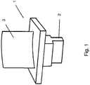
- the Fig. 1 shows a schematic example of a blade 1 of a turbomachine, such as a gas turbine or an aircraft engine.
- Shovel 1 shown can be arranged, for example as a blade on a rotor of a turbomachine, wherein the foot 2 of the blade 1 is received in a corresponding Schaufelfuß technique (not shown) of a rotor disk or the like.
- Schaufelfuß a Schaufelfuß technique
- the invention is also applicable to other types of blades having other blade shapes, with or without inner and outer shrouds, as well as other blade root shapes.
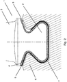
- FIG. 2 a section through a comparable blade with a differently shaped blade root 2 is shown, wherein in addition the Schaufelfußing 7 a rotor disk 6 is shown in the sectional view.
- a ductile layer 5 is applied to the thermal barrier coating 4.
- the ductile layer 5 can, as in the right part of the blade root 2 of the Fig. 2 is shown to be applied only over portions of the thermal barrier coating 4, so that in the other areas in which no ductile layer 5 is provided, a gap 8 between the boundary wall of Schaufelfußfact 7 and the thermal barrier coating 4 of the blade root 2 may be formed.
- the ductile layer 5 but also, as in the left part of the blade root 2 of the Fig. 2 shown is substantially applied over the entire area of the thermal barrier coating 4.
- the left and the right part of the Fig. 2 Thus, show two different embodiments with respect to the ductile layer. 5
- the thermal barrier coating 4 which is arranged in the embodiment shown on the blade root 2, but could also be arranged in other embodiments on the boundary wall of Schaufelfuß technique 7, used to a temperature gradient from the blade root 2 to the boundary wall of the Schaufelfußfact 7 and the discs - or rotor material in which the Schaufelfußfact 7 is formed to adjust. Due to the thermal barrier coating 4, it is possible to set a higher temperature in the blade root 2 during operation of the turbomachine than in the rotor disk 6 or the rotor. This makes it possible for the blade root 2 to provide a material optimized for higher operating temperatures, while for the rotor disk 6 a material optimized for a lower operating temperature can be used. Accordingly, the cooling of the blade root can be reduced without having to fear that the material of the rotor disk 6 is overheated.
- the rotor disk 6 could be formed of a nickel base material, while the blade or the blade root 2 could be formed from a nickel base superalloy with a higher service temperature or from another material with a higher service temperature, so that a temperature difference between the operating temperature of the thermal barrier coating 4 Shovel foot 2 and the operating temperature of the rotor disk 6 can be set in the order of 50 ° C to 100 ° C or above in order to be able to use the potential of the different materials of rotor disk 6 and blade 1 accordingly.
- thermal barrier coating suitable materials with low thermal conductivity come into consideration, such as ceramic thermal barrier coatings or thermal barrier coatings containing ceramic components.
- materials of or with aluminum oxide and / or zirconium oxide could be used.
- the ductile layer 5 which can be formed of a suitable ductile material, such as a metallic material with a sufficiently high elongation at break, is used in the Essentially, the protection of the thermal barrier coating by avoiding voltage spikes, which could result in particular in point or line contact of the blade root 2 or the heat insulating layer 4 disposed thereon with the Schaufelfußing 7.
- a ductile layer 5 possible manufacturing inaccuracies that could lead to such voltage spikes can be compensated in a simple manner and the thermal barrier coating can be protected against mechanical overloads.
- the ductile layer 5 may continue to perform additional functions, such as with regard to the prevention of fretting or the like.
Landscapes
- Engineering & Computer Science (AREA)
- Mechanical Engineering (AREA)
- General Engineering & Computer Science (AREA)
- Chemical & Material Sciences (AREA)
- Ceramic Engineering (AREA)
- Materials Engineering (AREA)
- Turbine Rotor Nozzle Sealing (AREA)
Applications Claiming Priority (1)
| Application Number | Priority Date | Filing Date | Title |
|---|---|---|---|
| DE102016201523.0A DE102016201523A1 (de) | 2016-02-02 | 2016-02-02 | Schaufel einer Strömungsmaschine mit Schaufelfusswärmedämmung |
Publications (1)
| Publication Number | Publication Date |
|---|---|
| EP3203029A1 true EP3203029A1 (fr) | 2017-08-09 |
Family
ID=57906508
Family Applications (1)
| Application Number | Title | Priority Date | Filing Date |
|---|---|---|---|
| EP17153140.3A Withdrawn EP3203029A1 (fr) | 2016-02-02 | 2017-01-25 | Aube de turbomachine dotée d'une isolation d'emplanture d'aube |
Country Status (3)
| Country | Link |
|---|---|
| US (1) | US20170218768A1 (fr) |
| EP (1) | EP3203029A1 (fr) |
| DE (1) | DE102016201523A1 (fr) |
Cited By (1)
| Publication number | Priority date | Publication date | Assignee | Title |
|---|---|---|---|---|
| EP3425166A1 (fr) * | 2017-07-07 | 2019-01-09 | MTU Aero Engines GmbH | Dispositif d'aube disque pour une turbomachine |
Families Citing this family (5)
| Publication number | Priority date | Publication date | Assignee | Title |
|---|---|---|---|---|
| US10309232B2 (en) * | 2012-02-29 | 2019-06-04 | United Technologies Corporation | Gas turbine engine with stage dependent material selection for blades and disk |
| US10047614B2 (en) * | 2014-10-09 | 2018-08-14 | Rolls-Royce Corporation | Coating system including alternating layers of amorphous silica and amorphous silicon nitride |
| EP3228819B1 (fr) * | 2016-04-08 | 2021-06-09 | Ansaldo Energia Switzerland AG | Aube comprenant des couches à cmc |
| US20210156267A1 (en) * | 2019-11-21 | 2021-05-27 | Applied Materials, Inc. | Methods for depositing protective coatings on turbine blades and other aerospace components |
| US12012870B1 (en) * | 2022-11-29 | 2024-06-18 | Rtx Corporation | Machinable coating for CMC and metal interface in a turbine section |
Citations (8)
| Publication number | Priority date | Publication date | Assignee | Title |
|---|---|---|---|---|
| US4417854A (en) * | 1980-03-21 | 1983-11-29 | Rockwell International Corporation | Compliant interface for ceramic turbine blades |
| WO1996041068A1 (fr) | 1995-06-07 | 1996-12-19 | National Research Council Of Canada | Barriere anti-usure par contact |
| US20070048142A1 (en) | 2005-08-26 | 2007-03-01 | Snecma | Assembly and method for the mounting of the foot of a blade of a turbine, blower, compressor, and turbine comprising such an assembly |
| EP2423442A2 (fr) | 2010-08-30 | 2012-02-29 | United Technologies Corporation | Bande de friction conforme électroformée |
| US8545183B2 (en) | 2007-09-06 | 2013-10-01 | Siemens Aktiengesellschaft | Seal coating between rotor blade and rotor disk slot in gas turbine engine |
| WO2013169271A1 (fr) | 2012-05-11 | 2013-11-14 | E. I. Du Pont De Nemours And Company | Aube de soufflante de turbine résistant à l'usure |
| EP2719865A1 (fr) | 2012-10-12 | 2014-04-16 | MTU Aero Engines GmbH | Insert pour connexions aube-disque de turbomachines |
| WO2014143364A2 (fr) * | 2013-03-14 | 2014-09-18 | United Technologies Corporation | Elément formé conjointement avec couche à faible conductivité |
-
2016
- 2016-02-02 DE DE102016201523.0A patent/DE102016201523A1/de not_active Withdrawn
-
2017
- 2017-01-25 EP EP17153140.3A patent/EP3203029A1/fr not_active Withdrawn
- 2017-01-31 US US15/420,197 patent/US20170218768A1/en not_active Abandoned
Patent Citations (8)
| Publication number | Priority date | Publication date | Assignee | Title |
|---|---|---|---|---|
| US4417854A (en) * | 1980-03-21 | 1983-11-29 | Rockwell International Corporation | Compliant interface for ceramic turbine blades |
| WO1996041068A1 (fr) | 1995-06-07 | 1996-12-19 | National Research Council Of Canada | Barriere anti-usure par contact |
| US20070048142A1 (en) | 2005-08-26 | 2007-03-01 | Snecma | Assembly and method for the mounting of the foot of a blade of a turbine, blower, compressor, and turbine comprising such an assembly |
| US8545183B2 (en) | 2007-09-06 | 2013-10-01 | Siemens Aktiengesellschaft | Seal coating between rotor blade and rotor disk slot in gas turbine engine |
| EP2423442A2 (fr) | 2010-08-30 | 2012-02-29 | United Technologies Corporation | Bande de friction conforme électroformée |
| WO2013169271A1 (fr) | 2012-05-11 | 2013-11-14 | E. I. Du Pont De Nemours And Company | Aube de soufflante de turbine résistant à l'usure |
| EP2719865A1 (fr) | 2012-10-12 | 2014-04-16 | MTU Aero Engines GmbH | Insert pour connexions aube-disque de turbomachines |
| WO2014143364A2 (fr) * | 2013-03-14 | 2014-09-18 | United Technologies Corporation | Elément formé conjointement avec couche à faible conductivité |
Cited By (1)
| Publication number | Priority date | Publication date | Assignee | Title |
|---|---|---|---|---|
| EP3425166A1 (fr) * | 2017-07-07 | 2019-01-09 | MTU Aero Engines GmbH | Dispositif d'aube disque pour une turbomachine |
Also Published As
| Publication number | Publication date |
|---|---|
| DE102016201523A1 (de) | 2017-08-03 |
| US20170218768A1 (en) | 2017-08-03 |
Similar Documents
| Publication | Publication Date | Title |
|---|---|---|
| EP3203029A1 (fr) | Aube de turbomachine dotée d'une isolation d'emplanture d'aube | |
| DE3401742C2 (de) | Rotor für einen Axialverdichter | |
| DE69838081T2 (de) | Turbinenschaufel | |
| DE69509893T2 (de) | Turbinengehäusesegment mit hinterschnittenen befestigungshaken | |
| DE102008023424B4 (de) | Verfahren für die mittige Anordnung von Zähnen auf Turbinenschaufeln mit Deckband | |
| EP2647795B1 (fr) | Système d'étanchéité pour turbomachine | |
| CH702553B1 (de) | Turbinenleitapparatbaugruppe. | |
| DE3431014A1 (de) | Reibtolerante ummantelung und dichtvorrichtung | |
| WO2006111427A1 (fr) | Aube de turbine presentant une plaque de recouvrement et une couche de protection appliquee sur cette plaque de recouvrement | |
| CH711981A2 (de) | Kühlsystem für eine mehrwandige Schaufel. | |
| DE102011056905A1 (de) | Kühlkanalsysteme für mit Beschichtungen überzogene Hochtemperaturkomponenten und zugehörige Verfahren | |
| EP2302174A2 (fr) | Turbine à gaz avec un joint à labyrinthe de la virole | |
| EP1500790A2 (fr) | Segment de virole pour une turbomachine | |
| EP3093372B1 (fr) | Procede de recouvrement destine a produire une combinaison de blindage d'extremite d'aubes et couche de protection contre l'erosion | |
| DE3345263A1 (de) | Keramische turbinenschaufel | |
| EP2921714A1 (fr) | Groupe de série d'aubes | |
| EP2084368A1 (fr) | Aube de turbine | |
| EP2719865A1 (fr) | Insert pour connexions aube-disque de turbomachines | |
| DE10202810A1 (de) | Turbinenlaufschaufel für den Läufer eines Gasturbinentriebwerks | |
| EP3412875A2 (fr) | Structure de rodage pour une turbomachine et procédé de fabrication d'une structure de rodage | |
| DE102016222720A1 (de) | Dichtungssystem für eine axiale Strömungsmaschine und axiale Strömungsmaschine | |
| DE3509192A1 (de) | Stroemungsmaschine mit mitteln zur kontrolle des radialspaltes | |
| DE102009026057A1 (de) | Dichtungsmechanismus mit Schwenkplatte und Seildichtung | |
| EP2581468A1 (fr) | Procédé d'application d'une couche de protection contre l'usure sur un composant de turbomachine | |
| DE102016211337A1 (de) | Verdickter radial äußerer Ringbereich eines Dichtfins |
Legal Events
| Date | Code | Title | Description |
|---|---|---|---|
| PUAI | Public reference made under article 153(3) epc to a published international application that has entered the european phase |
Free format text: ORIGINAL CODE: 0009012 |
|
| AK | Designated contracting states |
Kind code of ref document: A1 Designated state(s): AL AT BE BG CH CY CZ DE DK EE ES FI FR GB GR HR HU IE IS IT LI LT LU LV MC MK MT NL NO PL PT RO RS SE SI SK SM TR |
|
| AX | Request for extension of the european patent |
Extension state: BA ME |
|
| 17P | Request for examination filed |
Effective date: 20180205 |
|
| RBV | Designated contracting states (corrected) |
Designated state(s): AL AT BE BG CH CY CZ DE DK EE ES FI FR GB GR HR HU IE IS IT LI LT LU LV MC MK MT NL NO PL PT RO RS SE SI SK SM TR |
|
| GRAP | Despatch of communication of intention to grant a patent |
Free format text: ORIGINAL CODE: EPIDOSNIGR1 |
|
| INTG | Intention to grant announced |
Effective date: 20190319 |
|
| STAA | Information on the status of an ep patent application or granted ep patent |
Free format text: STATUS: THE APPLICATION IS DEEMED TO BE WITHDRAWN |
|
| 18D | Application deemed to be withdrawn |
Effective date: 20190730 |