EP3203029A1 - Blade of a turbomachine, having blade foot heat insulation - Google Patents
Blade of a turbomachine, having blade foot heat insulation Download PDFInfo
- Publication number
- EP3203029A1 EP3203029A1 EP17153140.3A EP17153140A EP3203029A1 EP 3203029 A1 EP3203029 A1 EP 3203029A1 EP 17153140 A EP17153140 A EP 17153140A EP 3203029 A1 EP3203029 A1 EP 3203029A1
- Authority
- EP
- European Patent Office
- Prior art keywords
- blade
- blade root
- barrier coating
- thermal barrier
- turbomachine
- Prior art date
- Legal status (The legal status is an assumption and is not a legal conclusion. Google has not performed a legal analysis and makes no representation as to the accuracy of the status listed.)
- Withdrawn
Links
Images
Classifications
-
- F—MECHANICAL ENGINEERING; LIGHTING; HEATING; WEAPONS; BLASTING
- F01—MACHINES OR ENGINES IN GENERAL; ENGINE PLANTS IN GENERAL; STEAM ENGINES
- F01D—NON-POSITIVE DISPLACEMENT MACHINES OR ENGINES, e.g. STEAM TURBINES
- F01D5/00—Blades; Blade-carrying members; Heating, heat-insulating, cooling or antivibration means on the blades or the members
- F01D5/02—Blade-carrying members, e.g. rotors
- F01D5/08—Heating, heat-insulating or cooling means
-
- F—MECHANICAL ENGINEERING; LIGHTING; HEATING; WEAPONS; BLASTING
- F01—MACHINES OR ENGINES IN GENERAL; ENGINE PLANTS IN GENERAL; STEAM ENGINES
- F01D—NON-POSITIVE DISPLACEMENT MACHINES OR ENGINES, e.g. STEAM TURBINES
- F01D5/00—Blades; Blade-carrying members; Heating, heat-insulating, cooling or antivibration means on the blades or the members
- F01D5/12—Blades
- F01D5/28—Selecting particular materials; Particular measures relating thereto; Measures against erosion or corrosion
- F01D5/284—Selection of ceramic materials
-
- F—MECHANICAL ENGINEERING; LIGHTING; HEATING; WEAPONS; BLASTING
- F01—MACHINES OR ENGINES IN GENERAL; ENGINE PLANTS IN GENERAL; STEAM ENGINES
- F01D—NON-POSITIVE DISPLACEMENT MACHINES OR ENGINES, e.g. STEAM TURBINES
- F01D5/00—Blades; Blade-carrying members; Heating, heat-insulating, cooling or antivibration means on the blades or the members
- F01D5/30—Fixing blades to rotors; Blade roots ; Blade spacers
- F01D5/3007—Fixing blades to rotors; Blade roots ; Blade spacers of axial insertion type
-
- F—MECHANICAL ENGINEERING; LIGHTING; HEATING; WEAPONS; BLASTING
- F01—MACHINES OR ENGINES IN GENERAL; ENGINE PLANTS IN GENERAL; STEAM ENGINES
- F01D—NON-POSITIVE DISPLACEMENT MACHINES OR ENGINES, e.g. STEAM TURBINES
- F01D5/00—Blades; Blade-carrying members; Heating, heat-insulating, cooling or antivibration means on the blades or the members
- F01D5/30—Fixing blades to rotors; Blade roots ; Blade spacers
- F01D5/3092—Protective layers between blade root and rotor disc surfaces, e.g. anti-friction layers
-
- F—MECHANICAL ENGINEERING; LIGHTING; HEATING; WEAPONS; BLASTING
- F05—INDEXING SCHEMES RELATING TO ENGINES OR PUMPS IN VARIOUS SUBCLASSES OF CLASSES F01-F04
- F05D—INDEXING SCHEME FOR ASPECTS RELATING TO NON-POSITIVE-DISPLACEMENT MACHINES OR ENGINES, GAS-TURBINES OR JET-PROPULSION PLANTS
- F05D2220/00—Application
- F05D2220/30—Application in turbines
- F05D2220/32—Application in turbines in gas turbines
-
- F—MECHANICAL ENGINEERING; LIGHTING; HEATING; WEAPONS; BLASTING
- F05—INDEXING SCHEMES RELATING TO ENGINES OR PUMPS IN VARIOUS SUBCLASSES OF CLASSES F01-F04
- F05D—INDEXING SCHEME FOR ASPECTS RELATING TO NON-POSITIVE-DISPLACEMENT MACHINES OR ENGINES, GAS-TURBINES OR JET-PROPULSION PLANTS
- F05D2260/00—Function
- F05D2260/20—Heat transfer, e.g. cooling
- F05D2260/231—Preventing heat transfer
-
- F—MECHANICAL ENGINEERING; LIGHTING; HEATING; WEAPONS; BLASTING
- F05—INDEXING SCHEMES RELATING TO ENGINES OR PUMPS IN VARIOUS SUBCLASSES OF CLASSES F01-F04
- F05D—INDEXING SCHEME FOR ASPECTS RELATING TO NON-POSITIVE-DISPLACEMENT MACHINES OR ENGINES, GAS-TURBINES OR JET-PROPULSION PLANTS
- F05D2300/00—Materials; Properties thereof
- F05D2300/60—Properties or characteristics given to material by treatment or manufacturing
- F05D2300/611—Coating
-
- Y—GENERAL TAGGING OF NEW TECHNOLOGICAL DEVELOPMENTS; GENERAL TAGGING OF CROSS-SECTIONAL TECHNOLOGIES SPANNING OVER SEVERAL SECTIONS OF THE IPC; TECHNICAL SUBJECTS COVERED BY FORMER USPC CROSS-REFERENCE ART COLLECTIONS [XRACs] AND DIGESTS
- Y02—TECHNOLOGIES OR APPLICATIONS FOR MITIGATION OR ADAPTATION AGAINST CLIMATE CHANGE
- Y02T—CLIMATE CHANGE MITIGATION TECHNOLOGIES RELATED TO TRANSPORTATION
- Y02T50/00—Aeronautics or air transport
- Y02T50/60—Efficient propulsion technologies, e.g. for aircraft
Definitions
- the present invention relates to an arrangement for fastening a blade root of a blade of a turbomachine in a Schaufelfuß technique and a blade for a turbomachine and a method for operating a turbomachine.
- turbomachines such as stationary gas turbines or aircraft engines
- a plurality of blades is provided, which are attached as blades to a rotating rotor or are arranged as stationary vanes in the turbomachine.
- the fluid of the turbomachine such as air
- the turbomachine passed through the turbomachine, so that after compression of the fluid in the compressor and ignition of a suitable fuel - fluid mixture in the combustion chamber, the effluent combustion gas can drive a rotor, which in turn can drive the compressor.
- both blades and vanes in the flow channel of the turbomachine must meet high demands, since they can be exposed to high temperatures, high mechanical loads and aggressive media.
- the material of the blades may be different than the material of the turbomachine components adjacent to the blades, such as the material of the discs of a rotor or other blade receptacles in which the blades are received.
- the use of different materials for the blades and adjacent components, such as rotor disks, housings, etc. arises due to the special and complex requirements for the blades and the associated high cost of the corresponding material for the blades and / or due to a different requirement profile of the blades adjacent components of the turbomachine, so that the same material as for the blades for such Components can not or should not be used.
- the EP 2 719 865 A1 describes an insert for a blade-disk connection of a turbomachine, wherein the insert is formed from a fiber material and / or foam material, in which a lubricant may be incorporated in order to reduce the wear during a relative movement of the blade with respect to the blade receptacle.
- the WO 96/41068 A1 is also proposed an insert between the blade and blade receptacle, which is arranged by adhesive on one of the contact surfaces.
- the US Pat. No. 8,545,183 B2 suggests sealing a gap between a blade root and a blade root receiver by a corresponding coating.
- the US 2007/0048142 A1 In turn, to improve resistance to contact pressures in a paddle disc compound, the provision of a non-metallic layer with polyamide is disclosed, while the US Pat EP 2 423 442 A2 proposes a rub strip, wherein additionally an electrically insulating material is provided to prevent damage due to the electromotive forces.
- the WO 2013/169271 A1 suggests for the blade root of a blade of a fan, the provision of a plastic fabric in order to avoid wear of the blade root in a Schaufelfuß technique.
- the present invention is based on the fact that blades and blade receptacles in a turbomachine are preferably to be operated at different operating temperatures in order to be able to use appropriately optimized materials for the different desired operating temperatures. Accordingly, it is proposed to set a temperature gradient in the area of the blade-blade receiving connection, for example between a blade root of a blade and a blade root receiver in a rotor disk, so that the blade root can be operated at a higher operating temperature than the material forming the blade root receiver. As a result, cooling of the blade root area can be dispensed with or at least reduced, and the blade root can be manufactured from a material which is optimized for higher operating temperatures.
- the blade root temperature during operation of the turbomachine according to the invention can be set so that a limit of the ductility of the material from which the blade root is formed is exceeded, ie the blade root has a minimum ductility, so that no brittle material behavior of the material of the blade root during operation the turbomachine occurs.
- the blade root receiving temperature ie the temperature experienced by the material of the blade root during operation of the turbomachine
- the blade root receiving temperature can be selected such that a limit value of the strength of the material is exceeded, ie a sufficient strength is maintained even at the operating temperature of the turbomachine and / or that a limit of the creep rate and / or the oxidation or corrosion rate of the material is exceeded, that is, the oxidation or the creep or creep can be kept below critical values.
- Operating temperature of the turbomachine is understood to be the temperature of the corresponding components or components which are maximally achieved in normal continuous operation or at maximum power of the turbomachine.
- a thermal barrier coating be provided which enables the setting of a corresponding temperature gradient between the blade root and the blade root receiver.
- the thermal barrier coating may accordingly be formed of a material which has a low thermal conductivity and, in particular, has a lower thermal conductivity than the material of the blade root and the material of the blade root receiver.
- the thermal barrier coating may preferably be formed from a ceramic material such as alumina and / or zirconia or comprise such a ceramic material.
- the thermal barrier coating can be chosen so that the thermal conductivity of the thermal barrier coating is less than or equal to 50 W / mK and in particular less than or equal to 50 W / mK, preferably less than or equal to 1 W / mK.
- the thermal barrier coating may be applied as a coating either on the blade root or on the boundary wall of the Schaufelfuß technique in an arrangement of a blade root of a blade in a Schaufelfußability the turbomachine or be arranged as a separate insert between the corresponding components.
- the thermal barrier coating may be provided at least in the area of strong heat transfer between the blade root and the blade root receiver, preferably in the entire contact area between the blade root and the blade root receiver.
- the blade and the blade root receiver can be any suitable components of a turbomachine, in particular rotor blades, which are arranged in a rotor, in particular a rotor disk.
- a ductile layer can be deposited on the thermal barrier coating, the ductility of which is in particular greater than the ductility of the thermal barrier coating. Through such a ductile layer mechanical stress peaks can be avoided or reduced by appropriate deformation of the ductile layer.
- the ductile layer may accordingly be formed from a metallic material.
- the ductile layer may in particular have an elongation at break of more than 5%, preferably more than 10%.
- blade or blade root portions of TiAl alloys or molybdenum base alloys while the associated rotor disc is made of a Ni-based alloy, particularly nickel-base superalloy, such as titanium oxide.
- INCONEL alloy 718 (trade name of Special Metals Corp.) may be formed.
- alloys With base alloys or alloy designations with alloy information with the name of chemical elements in the first places alloys are called, which have the said chemical elements as components with the largest proportion.
- Superalloys refer to alloys that still have sufficient structural strengths at high temperatures of over half the melting temperature.
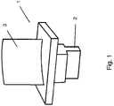
- the Fig. 1 shows a schematic example of a blade 1 of a turbomachine, such as a gas turbine or an aircraft engine.
- Shovel 1 shown can be arranged, for example as a blade on a rotor of a turbomachine, wherein the foot 2 of the blade 1 is received in a corresponding Schaufelfuß technique (not shown) of a rotor disk or the like.
- Schaufelfuß a Schaufelfuß technique
- the invention is also applicable to other types of blades having other blade shapes, with or without inner and outer shrouds, as well as other blade root shapes.
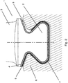
- FIG. 2 a section through a comparable blade with a differently shaped blade root 2 is shown, wherein in addition the Schaufelfußing 7 a rotor disk 6 is shown in the sectional view.
- a ductile layer 5 is applied to the thermal barrier coating 4.
- the ductile layer 5 can, as in the right part of the blade root 2 of the Fig. 2 is shown to be applied only over portions of the thermal barrier coating 4, so that in the other areas in which no ductile layer 5 is provided, a gap 8 between the boundary wall of Schaufelfußfact 7 and the thermal barrier coating 4 of the blade root 2 may be formed.
- the ductile layer 5 but also, as in the left part of the blade root 2 of the Fig. 2 shown is substantially applied over the entire area of the thermal barrier coating 4.
- the left and the right part of the Fig. 2 Thus, show two different embodiments with respect to the ductile layer. 5
- the thermal barrier coating 4 which is arranged in the embodiment shown on the blade root 2, but could also be arranged in other embodiments on the boundary wall of Schaufelfuß technique 7, used to a temperature gradient from the blade root 2 to the boundary wall of the Schaufelfußfact 7 and the discs - or rotor material in which the Schaufelfußfact 7 is formed to adjust. Due to the thermal barrier coating 4, it is possible to set a higher temperature in the blade root 2 during operation of the turbomachine than in the rotor disk 6 or the rotor. This makes it possible for the blade root 2 to provide a material optimized for higher operating temperatures, while for the rotor disk 6 a material optimized for a lower operating temperature can be used. Accordingly, the cooling of the blade root can be reduced without having to fear that the material of the rotor disk 6 is overheated.
- the rotor disk 6 could be formed of a nickel base material, while the blade or the blade root 2 could be formed from a nickel base superalloy with a higher service temperature or from another material with a higher service temperature, so that a temperature difference between the operating temperature of the thermal barrier coating 4 Shovel foot 2 and the operating temperature of the rotor disk 6 can be set in the order of 50 ° C to 100 ° C or above in order to be able to use the potential of the different materials of rotor disk 6 and blade 1 accordingly.
- thermal barrier coating suitable materials with low thermal conductivity come into consideration, such as ceramic thermal barrier coatings or thermal barrier coatings containing ceramic components.
- materials of or with aluminum oxide and / or zirconium oxide could be used.
- the ductile layer 5 which can be formed of a suitable ductile material, such as a metallic material with a sufficiently high elongation at break, is used in the Essentially, the protection of the thermal barrier coating by avoiding voltage spikes, which could result in particular in point or line contact of the blade root 2 or the heat insulating layer 4 disposed thereon with the Schaufelfußing 7.
- a ductile layer 5 possible manufacturing inaccuracies that could lead to such voltage spikes can be compensated in a simple manner and the thermal barrier coating can be protected against mechanical overloads.
- the ductile layer 5 may continue to perform additional functions, such as with regard to the prevention of fretting or the like.
Abstract
Die vorliegende Erfindung betrifft eine Anordnung zur Befestigung eines Schaufelfußes (2) einer Schaufel (1) einer Strömungsmaschine in einer Schaufelfußaufnahme (7) mit einer Schaufel mit einem Schaufelfuß aus einem ersten Material und einer Schaufelfußaufnahme aus einem zweiten Material, wobei zwischen dem Schaufelfuß und der Schaufelfußaufnahme eine Wärmedämmschicht (4) angeordnet ist. Außerdem betrifft die Erfindung eine Schaufel mit einem Schaufelfuß mit einer Wärmedämmschicht sowie ein Verfahren zum Betrieb einer Strömungsmaschine, bei welchem eine Schaufel mit einem Schaufelfuß (2) in einer Schaufelfußaufnahme (7) aufgenommen ist und bei dem eine Schaufelfußtemperatur eingestellt wird, die über der Schaufelfußaufnahmetemperatur ist.The present invention relates to an arrangement for fastening a blade root (2) of a blade (1) of a turbomachine in a Schaufelfußaufnahme (7) with a blade having a blade root of a first material and a Schaufelfußaufnahme of a second material, wherein between the blade root and the Schaufelfußaufnahme a thermal barrier coating (4) is arranged. Moreover, the invention relates to a blade with a blade root with a thermal barrier coating and a method for operating a turbomachine, in which a blade with a blade root (2) is received in a Schaufelfußaufnahme (7) and in which a Schaufelfußtemperatur is set, which is above the Schaufelfußaufnahmetemperatur is.
Description
Die vorliegende Erfindung betrifft eine Anordnung zur Befestigung eines Schaufelfußes einer Schaufel einer Strömungsmaschine in einer Schaufelfußaufnahme sowie eine Schaufel für eine Strömungsmaschine und ein Verfahren zum Betrieb einer Strömungsmaschine.The present invention relates to an arrangement for fastening a blade root of a blade of a turbomachine in a Schaufelfußaufnahme and a blade for a turbomachine and a method for operating a turbomachine.
Bei Strömungsmaschinen, wie stationären Gasturbinen oder Flugtriebwerken, ist eine Vielzahl von Schaufeln vorgesehen, die als Laufschaufeln an einem sich drehenden Rotor befestigt sind oder als Leitschaufeln ortsfest in der Strömungsmaschine angeordnet sind. Im Bereich der Schaufelblätter der Leitschaufeln und der Laufschaufeln wird das Fluid der Strömungsmaschine, wie beispielsweise Luft, durch die Strömungsmaschine geleitet, sodass nach einer Verdichtung des Fluids im Verdichter bzw. Kompressor und Zündung eines geeigneten Brennstoff - Fluid - Gemischs in der Brennkammer das ausströmende Verbrennungsgas einen Rotor antreiben kann, der wiederum den Verdichter antreiben kann. Entsprechend müssen sowohl Laufschaufeln als auch Leitschaufeln im Strömungskanal der Strömungsmaschine hohen Anforderungen gerecht werden, da sie hohen Temperaturen, hohen mechanischen Belastungen sowie aggressiven Medien ausgesetzt sein können. Folglich ist es häufig vorteilhaft und/oder notwendig die Schaufeln aus einem bestimmten Material zu fertigen, welches die speziellen Anforderungen erfüllt. Insbesondere kann das Material der Schaufeln unterschiedlich zu dem Material der zu den Schaufeln benachbarten Komponenten der Strömungsanlage sein, wie beispielsweise das Material der Scheiben eines Rotors oder sonstiger Schaufelaufnahmen, in denen die Schaufeln aufgenommen sind. Die Verwendung unterschiedlicher Materialien für die Schaufeln und benachbarte Komponenten, wie Rotorscheiben, Gehäuse usw. ergibt sich aufgrund der speziellen und aufwändigen Anforderungen für die Schaufeln und die damit verbundenen hohen Kosten für das entsprechende Material für die Schaufeln und/oder aufgrund eines unterschiedlichen Anforderungsprofils der zu den Schaufeln benachbarten Komponenten der Strömungsmaschine, sodass das gleiche Material wie für die Schaufeln für derartige Komponenten nicht eingesetzt werden kann oder soll.In turbomachines, such as stationary gas turbines or aircraft engines, a plurality of blades is provided, which are attached as blades to a rotating rotor or are arranged as stationary vanes in the turbomachine. In the area of the blades of the guide vanes and the blades, the fluid of the turbomachine, such as air, passed through the turbomachine, so that after compression of the fluid in the compressor and ignition of a suitable fuel - fluid mixture in the combustion chamber, the effluent combustion gas can drive a rotor, which in turn can drive the compressor. Accordingly, both blades and vanes in the flow channel of the turbomachine must meet high demands, since they can be exposed to high temperatures, high mechanical loads and aggressive media. Consequently, it is often advantageous and / or necessary to manufacture the blades from a particular material that meets the specific requirements. In particular, the material of the blades may be different than the material of the turbomachine components adjacent to the blades, such as the material of the discs of a rotor or other blade receptacles in which the blades are received. The use of different materials for the blades and adjacent components, such as rotor disks, housings, etc. arises due to the special and complex requirements for the blades and the associated high cost of the corresponding material for the blades and / or due to a different requirement profile of the blades adjacent components of the turbomachine, so that the same material as for the blades for such Components can not or should not be used.
Damit sind jedoch Verbindungen der Schaufel zu benachbarten Komponenten aus unterschiedlichen Materialien notwendig, die entsprechende Probleme mit sich bringen können.This, however, connections of the blade to adjacent components made of different materials are necessary, which can bring corresponding problems.
An den Verbindungsstellen zwischen den einzelnen Komponenten, wie den Schaufeln und insbesondere den Laufschaufeln einerseits und Rotorscheiben, in denen sie aufgenommen sind, andererseits, kann es durch Relativbewegung beispielsweise zu Verschleiß kommen, aber auch andere Probleme durch Korrosion, insbesondere Fretting, oder durch mechanische Belastungen durch Spannungsspitzen aufgrund von Linien - oder Punktkontakten zwischen Schaufel und Scheibe können auftreten.At the junctions between the individual components, such as the blades and in particular the blades on the one hand and rotor disks in which they are accommodated, on the other hand, it may be due to relative movement, for example wear, but also other problems due to corrosion, especially fretting, or by mechanical loads Voltage spikes due to line or point contacts between blade and disc can occur.
Um diese Probleme zu lösen, wird beispielsweise in der
Die
Obwohl mit den verschiedenen Schaufelfuß - Schaufelfußaufnahme - Verbindungen aus dem Stand der Technik bereits die Möglichkeit geschaffen wurde, für die Schaufel und die Schaufelfußaufnahme unterschiedliche Werkstoffe einzusetzen und diese Komponenten wirkungsvoll zu verbinden, besteht weiterhin ein Bedarf dafür, für die verschiedenen Komponenten Schaufel und Schaufelaufnahme speziell angepasste Werkstoffe einzusetzen, wobei jedoch der Verbindungsbereich der Komponenten so ausgebildet sein soll, dass bei einer maximalen Ausnutzung des Potentials der Werkstoffe eine hohe Lebensdauer der Verbindung der Komponenten und ein optimaler Einsatz der einzelnen Komponenten gegeben ist. Gleichzeitig soll eine entsprechende Lösung einfach und zuverlässig herstellbar und einsetzbar sein.Although the various blade-foot-blade-foot-joint connections from the prior art have already made it possible to use different materials for the blade and the blade root receiver and to connect these components effectively, there is still a need for a special blade and blade pick-up for the various components use adapted materials, but the connection area of the components should be designed so that with a maximum utilization of the potential of the materials a long service life of the compound of the components and an optimal use of the individual components is given. At the same time a corresponding solution should be easy and reliable to manufacture and use.
Diese Aufgabe wird gelöst durch eine Anordnung mit den Merkmalen des Anspruchs 1 sowie eine Schaufel mit den Merkmalen des Anspruchs 8 und ein Verfahren mit den Merkmalen des Anspruchs 14. Vorteilhafte Ausgestaltungen sind Gegenstand der abhängigen Ansprüche.This object is achieved by an arrangement having the features of
Bei der vorliegenden Erfindung wird darauf abgestellt, dass Schaufeln und Schaufelaufnahmen in einer Strömungsmaschine bevorzugt bei unterschiedlichen Betriebstemperaturen betrieben werden sollen, um für die unterschiedlichen angestrebten Betriebstemperaturen entsprechend gezielt, optimierte Werkstoffe einsetzen zu können. Entsprechend wird vorgeschlagen, im Bereich der Schaufel - Schaufelaufnahme - Verbindung, beispielsweise zwischen einem Schaufelfuß einer Laufschaufel und einer Schaufelfußaufnahme in einer Rotorscheibe, einen Temperaturgradienten einzustellen, sodass der Schaufelfuß bei einer höheren Betriebstemperatur betrieben werden kann als das Material, das die Schaufelfußaufnahme bildet. Dadurch kann auf eine Kühlung des Schaufelfußbereichs verzichtet werden oder diese zumindest verringert werden und der Schaufelfuß kann aus einem Material gefertigt werden, welches für höhere Einsatztemperaturen optimiert ist. Dadurch stellt sich auch nicht mehr das Problem, dass an der Verbindungsstelle der Schaufel zur Schaufelaufnahme der Schaufelfuß aufgrund der an die Schaufelfußaufnahme angepassten Temperatur eigentlich bei zu niedrigen Temperaturen betrieben werden muss, da der Werkstoff der Schaufel auf höhere Temperaturen im Strömungskanal ausgerichtet ist, sodass der Werkstoff in dem Temperaturbereich an der Schaufelfußaufnahme bereits spröde Eigenschaften zeigt, während die Temperatur für den Werkstoff der Schaufelaufnahme eigentlich zu hoch ist und dieser durch Überhitzung beschädigt werden kann, wenn die Temperatur im Bereich der Schaufel - Schaufelaufnahme - Verbindung aufgrund der hohen Schaufeltemperaturen in der Schaufelfußaufnahme erhöht ist.The present invention is based on the fact that blades and blade receptacles in a turbomachine are preferably to be operated at different operating temperatures in order to be able to use appropriately optimized materials for the different desired operating temperatures. Accordingly, it is proposed to set a temperature gradient in the area of the blade-blade receiving connection, for example between a blade root of a blade and a blade root receiver in a rotor disk, so that the blade root can be operated at a higher operating temperature than the material forming the blade root receiver. As a result, cooling of the blade root area can be dispensed with or at least reduced, and the blade root can be manufactured from a material which is optimized for higher operating temperatures. As a result, this is no longer the Problem that at the junction of the blade to the blade receiving the blade root due to the adapted to the Schaufelfußaufnahme temperature actually has to be operated at too low temperatures, since the material of the blade is aligned to higher temperatures in the flow channel, so that the material in the temperature range at the Schaufelfußaufnahme already shows brittle properties, while the temperature for the material of the blade receptacle is actually too high and this can be damaged by overheating, when the temperature in the area of the blade-blade receiving connection is increased due to the high blade temperatures in the Schaufelfußaufnahme.
Entsprechend kann die Schaufelfußtemperatur beim Betrieb der Strömungsmaschine gemäß der Erfindung so eingestellt werden, dass ein Grenzwert der Duktilität des Materials, aus dem der Schaufelfuß gebildet ist, überschritten wird, also der Schaufelfuß eine Mindestduktilität aufweist, sodass kein sprödes Werkstoffverhalten des Werkstoffs des Schaufelfußes beim Betrieb der Strömungsmaschine auftritt. Gleichzeitig oder alternativ kann die Schaufelfußaufnahmetemperatur, also die Temperatur, die der Werkstoff des Schaufelfußaufnahme beim Betrieb der Strömungsmaschine erfährt, so gewählt werden, dass ein Grenzwert der Festigkeit des Materials überschritten wird, das heißt dass eine ausreichende Festigkeit auch bei Betriebstemperatur der Strömungsmaschine erhalten bleibt und/oder dass ein Grenzwert der Kriechrate und/oder der Oxidation- oder Korrosionsrate des Materials unterschritten wird, das heißt, dass die Oxidation bzw. Korrosion oder das Kriechen unter kritischen Werten gehalten werden können. Unter Betriebstemperatur der Strömungsmaschine wird die Temperatur der entsprechenden Bauteile oder Komponenten verstanden, die maximal im normalen Dauerbetrieb oder bei maximaler Leistung der Strömungsmaschine erreicht werden.Accordingly, the blade root temperature during operation of the turbomachine according to the invention can be set so that a limit of the ductility of the material from which the blade root is formed is exceeded, ie the blade root has a minimum ductility, so that no brittle material behavior of the material of the blade root during operation the turbomachine occurs. At the same time or as an alternative, the blade root receiving temperature, ie the temperature experienced by the material of the blade root during operation of the turbomachine, can be selected such that a limit value of the strength of the material is exceeded, ie a sufficient strength is maintained even at the operating temperature of the turbomachine and / or that a limit of the creep rate and / or the oxidation or corrosion rate of the material is exceeded, that is, the oxidation or the creep or creep can be kept below critical values. Operating temperature of the turbomachine is understood to be the temperature of the corresponding components or components which are maximally achieved in normal continuous operation or at maximum power of the turbomachine.
Um einen derartigen Betrieb einer Strömungsmaschine zu ermöglichen, wird vorgeschlagen, dass zwischen dem Schaufelfuß und der Schaufelfußaufnahme bei einer Anordnung einer Schaufel in einer Schaufelfußaufnahme eine Wärmedämmschicht vorgesehen wird, die die Einstellung eines entsprechenden Temperaturgradienten zwischen dem Schaufelfuß und der Schaufelfußaufnahme ermöglicht. Die Wärmedämmschicht kann entsprechend aus einem Material gebildet sein, welches eine geringe Wärmeleitfähigkeit aufweist und insbesondere eine geringere Wärmeleitfähigkeit aufweist als das Material des Schaufelfußes und das Material der Schaufelfußaufnahme.In order to enable such an operation of a turbomachine, it is proposed that between the blade root and the blade root receiving means, when a blade is arranged in a blade root receiving means, a thermal barrier coating be provided which enables the setting of a corresponding temperature gradient between the blade root and the blade root receiver. The thermal barrier coating may accordingly be formed of a material which has a low thermal conductivity and, in particular, has a lower thermal conductivity than the material of the blade root and the material of the blade root receiver.
Die Wärmedämmschicht kann vorzugsweise aus einem keramischen Material, wie Aluminiumoxid und/oder Zirkonoxid gebildet sein oder ein derartiges keramisches Material umfassen.The thermal barrier coating may preferably be formed from a ceramic material such as alumina and / or zirconia or comprise such a ceramic material.
Vorzugsweise kann die Wärmedämmschicht so gewählt werden, dass die Wärmeleitfähigkeit der Wärmedämmschicht kleiner oder gleich 50 W/mK und insbesondere kleiner oder gleich 50 W/mK, vorzugsweise kleiner oder gleich 1 W/mK beträgt.Preferably, the thermal barrier coating can be chosen so that the thermal conductivity of the thermal barrier coating is less than or equal to 50 W / mK and in particular less than or equal to 50 W / mK, preferably less than or equal to 1 W / mK.
Die Wärmedämmschicht kann bei einer Anordnung eines Schaufelfußes einer Schaufel in einer Schaufelfußaufnahme der Strömungsmaschine entweder auf dem Schaufelfuß oder an der Begrenzungswand der Schaufelfußaufnahme als Beschichtung aufgebracht sein oder als separate Einlage zwischen den entsprechenden Bauteilen angeordnet sein. Die Wärmedämmschicht kann hierbei zumindest im Bereich starker Wärmeübertragung zwischen Schaufelfuß und Schaufelfußaufnahme, vorzugsweise im gesamten Kontaktbereich zwischen Schaufelfuß und Schaufelfußaufnahme vorgesehen sein. Bei der Schaufel und der Schaufelfußaufnahme kann es sich um beliebige, geeignete Komponenten einer Strömungsmaschine handeln, insbesondere um Laufschaufeln, die in einem Rotor insbesondere einer Rotorscheibe angeordnet sind.The thermal barrier coating may be applied as a coating either on the blade root or on the boundary wall of the Schaufelfußaufnahme in an arrangement of a blade root of a blade in a Schaufelfußaufnahme the turbomachine or be arranged as a separate insert between the corresponding components. The thermal barrier coating may be provided at least in the area of strong heat transfer between the blade root and the blade root receiver, preferably in the entire contact area between the blade root and the blade root receiver. The blade and the blade root receiver can be any suitable components of a turbomachine, in particular rotor blades, which are arranged in a rotor, in particular a rotor disk.
Um die mechanischen Belastungen der Wärmedämmschicht klein zu halten, kann auf der Wärmedämmschicht eine duktile Schicht abgeschieden sein, deren Duktilität insbesondere größer ist als die Duktilität der Wärmedämmschicht. Durch eine derartige duktile Schicht können mechanische Spannungsspitzen durch entsprechende Verformung der duktilen Schicht vermieden bzw. abgebaut werden.In order to keep the mechanical loads of the thermal barrier coating small, a ductile layer can be deposited on the thermal barrier coating, the ductility of which is in particular greater than the ductility of the thermal barrier coating. Through such a ductile layer mechanical stress peaks can be avoided or reduced by appropriate deformation of the ductile layer.
Die duktile Schicht kann entsprechend aus einem metallischen Material gebildet sein. Die duktile Schicht kann insbesondere eine Bruchdehnung von mehr als 5%, vorzugsweise mehr als 10% aufweisen.The ductile layer may accordingly be formed from a metallic material. The ductile layer may in particular have an elongation at break of more than 5%, preferably more than 10%.
Entsprechend wird nach einen weiteren Aspekt der vorliegenden Erfindung, für den selbstständig und unabhängig von anderen Aspekten der vorliegenden Erfindung eine Schaufel für eine Strömungsmaschine beansprucht, bei der der Schaufelfuß eine entsprechende Wärmedämmschicht aufweist, wie sie bereits oben bezüglich der Anordnung einer Schaufel in einer Schaufelaufnahme beschrieben worden ist.Accordingly, according to a further aspect of the present invention, independently and independently of other aspects of the present invention claims a blade for a turbomachine in which the blade root has a corresponding thermal barrier coating, as described above with respect to the arrangement of a blade in a blade receptacle has been.
Entsprechend ist es möglich den Schaufelfuß einer Laufschaufel und eine Schaufelfußaufnahme in einer Rotorscheibe bei unterschiedlichen Temperaturen zu betreiben, sodass auch der Einsatz unterschiedlicher Werkstoffe für Schaufeln bzw. Schaufelfußbereiche und die Schaufelaufnahme enthaltenden Bauteile, wie Rotorscheiben, erleichtert wird. Dies ist insbesondere bei den neuen Generationen von Strömungsmaschinen bzw. Flugtriebwerken vorteilhaft, die mit einem Getriebefan ausgestattet sind. In derartigen Strömungsmaschinen sind die Anforderungen insbesondere an Laufschaufeln besonders hoch, da zur Steigerung des Wirkungsgrades beispielsweise die Niederdruckturbine bei höheren Umdrehungszahlen und mit höheren Gaseintrittstemperaturen betrieben wird als bei Flugtriebwerken früherer Generationen.Accordingly, it is possible to operate the blade root of a blade and a Schaufelfußaufnahme in a rotor disk at different temperatures, so that the use of different materials for blades or Schaufelfußbereiche and the blade receiving components, such as rotor disks is facilitated. This is particularly advantageous in the new generations of turbomachines or aircraft engines, which are equipped with a Getriebefan. In such turbomachines, the requirements are particularly high on blades in particular, since to increase the efficiency, for example, the low-pressure turbine is operated at higher speeds and higher gas inlet temperatures than in aircraft engines of earlier generations.
Mit der vorliegenden Erfindung ist es beispielsweise möglich Schaufel oder Schaufelfußbereiche aus TiAl - Legierungen oder Molybdän - Basislegierungen einzusetzen, während die zugehörige Rotorscheibe aus einer Ni - Basislegierung, insbesondere Nickelbasis - Superlegierung, wie z.B. INCONEL alloy 718 (Handelsname der Special Metals Corp.) gebildet sein kann.For example, with the present invention, it is possible to use blade or blade root portions of TiAl alloys or molybdenum base alloys, while the associated rotor disc is made of a Ni-based alloy, particularly nickel-base superalloy, such as titanium oxide. INCONEL alloy 718 (trade name of Special Metals Corp.) may be formed.
Mit Basislegierungen bzw. Legierungsbezeichnungen mit Legierungsangaben mit Nennung von chemischen Elementen an den ersten Stellen werden Legierungen bezeichnet, die die genannten chemischen Elemente als Komponenten mit den größten Anteil aufweisen. Superlegierungen bezeichnen Legierungen, die bei hohen Temperaturen von über der Hälfte der Schmelztemperatur noch ausreichende strukturelle Festigkeiten aufweisen.With base alloys or alloy designations with alloy information with the name of chemical elements in the first places alloys are called, which have the said chemical elements as components with the largest proportion. Superalloys refer to alloys that still have sufficient structural strengths at high temperatures of over half the melting temperature.
Die beigefügten Zeichnungen zeigen in rein schematischer Weise in
- Fig. 1
- eine perspektivische Darstellung einer Schaufel einer Strömungsmaschine und in
- Fig. 2
- eine Schnittansicht durch einen Fußbereich einer weiteren Schaufel einer Strömungsmaschine.
- Fig. 1
- a perspective view of a blade of a turbomachine and in
- Fig. 2
- a sectional view through a foot portion of another blade of a turbomachine.
Weitere Vorteile, Kennzeichen und Merkmale der vorliegenden Erfindung werden bei der nachfolgenden detaillierten Beschreibung der Ausführungsbeispiele deutlich. Allerdings ist die Erfindung nicht auf diese Ausführungsbeispiele beschränkt.Further advantages, characteristics and features of the present invention will become apparent in the following detailed description of the embodiments. However, the invention is not limited to these embodiments.
Die
In
Aus der Schnittdarstellung der
Zusätzlich zur Wärmedämmschicht 4 ist bei dem Ausführungsbeispiel der
Erfindungsgemäß wird die Wärmedämmschicht 4, die bei dem gezeigten Ausführungsbeispiel am Schaufelfuß 2 angeordnet ist, aber bei anderen Ausführungsbeispielen auch an der Begrenzungswand der Schaufelfußaufnahme 7 angeordnet sein könnte, dazu verwendet, einen Temperaturgradienten vom Schaufelfuß 2 zur Begrenzungswand der Schaufelfußaufnahme 7 bzw. dem Scheiben - bzw. Rotorwerkstoff, in dem die Schaufelfußaufnahme 7 ausgebildet ist, einzustellen. Durch die Wärmedämmschicht 4 ist es möglich im Schaufelfuß 2 beim Betrieb der Strömungsmaschine eine höhere Temperatur einzustellen, als in der Rotorscheibe 6 bzw. dem Rotor. Dadurch ist es möglich für den Schaufelfuß 2 einen für höhere Betriebstemperaturen optimierten Werkstoff vorzusehen, während für die Rotorscheibe 6 ein für eine niedrigere Betriebstemperatur optimierter Werkstoff eingesetzt werden kann. Entsprechend kann auch die Kühlung des Schaufelfußes reduziert werden, ohne befürchten zu müssen, dass das Material der Rotorscheibe 6 überhitzt wird.According to the invention, the
Beispielswiese könnte die Rotorscheibe 6 aus einem Nickelbasiswerkstoff gebildet sein, während die Schaufel bzw. der Schaufelfuß 2 aus einer Nickelbasissuperlegierung mit einer höheren Einsatztemperatur oder aus einem anderen Material mit höherer Einsatztemperatur gebildet sein könnte, sodass sich über der Wärmedämmschicht 4 ein Temperaturunterschied zwischen der Betriebstemperatur des Schaufelfußes 2 und der Betriebstemperatur der Rotorscheibe 6 in der Größenordnung von 50°C bis 100°C oder darüber eingestellt werden kann, um das Potential der verschiedenen Werkstoffe von Rotorscheibe 6 und Schaufel 1 entsprechend ausreizen zu können.For example, the
Als Wärmedämmschicht kommen entsprechende Materialien mit geringer Wärmeleitfähigkeit in Betracht, wie beispielsweise keramische Wärmedämmschichten bzw. Wärmedämmschichten, die keramische Anteile enthalten. Beispielhaft könnten Materialien aus oder mit Aluminiumoxid und/oder Zirkonoxid zum Einsatz kommen.As a thermal barrier coating suitable materials with low thermal conductivity come into consideration, such as ceramic thermal barrier coatings or thermal barrier coatings containing ceramic components. By way of example, materials of or with aluminum oxide and / or zirconium oxide could be used.
Die duktile Schicht 5, die aus einem geeigneten duktilen Werkstoff, wie beispielswiese einem metallischen Material mit ausreichend hoher Bruchdehnung gebildet werden kann, dient im Wesentlichen dem Schutz der Wärmedämmschicht durch Vermeidung von Spannungsspitzen, die sich insbesondere bei punkt - oder linienförmigem Kontakt des Schaufelfußes 2 bzw. der darauf angeordneten Wärmedämmschicht 4 mit der Schaufelfußaufnahme 7 ergeben könnten. Durch eine duktile Schicht 5 können mögliche Fertigungsungenauigkeiten, die zu derartigen Spannungsspitzen führen könnten, in einfacher Weise ausgeglichen werden und die Wärmedämmschicht kann vor mechanischen Überlastungen geschützt werden. Darüber hinaus kann die duktile Schicht 5 weiterhin zusätzliche Funktionen, wie beispielsweise hinsichtlich der Vermeidung von Reibverschleiß oder dergleichen übernehmen.The
Obwohl die vorliegende Erfindung anhand der Ausführungsbeispiele detailliert beschrieben worden ist, ist für den Fachmann selbstverständlich, dass die Erfindung nicht auf diese Ausführungsbeispiele beschränkt ist, sondern dass vielmehr Abwandlungen in der Weise möglich sind, dass einzelne Merkmale weggelassen oder andersartige Kombinationen von Merkmalen verwirklicht werden können, solange der Schutzumfang der beigefügten Ansprüche nicht verlassen wird. Die Offenbarung der vorliegenden Erfindung schließt sämtliche Kombinationen der vorgestellten Einzelmerkmale mit ein.Although the present invention has been described in detail with reference to the embodiments, it will be understood by those skilled in the art that the invention is not limited to these embodiments, but rather modifications are possible in the manner that individual features omitted or other combinations of features can be realized as long as the scope of protection of the appended claims is not abandoned. The disclosure of the present invention includes all combinations of the featured individual features.
- 11
- Schaufelshovel
- 22
- Schaufelfußblade
- 33
- Schaufelblattairfoil
- 44
- Wärmedämmschichtthermal barrier
- 55
- duktile Schichtductile layer
- 66
- Rotorscheiberotor disc
- 77
- SchaufelfußaufnahmeSchaufelfußaufnahme
- 88th
- Spaltgap
Claims (16)
dadurch gekennzeichnet, dass
zwischen dem Schaufelfuß und der Schaufelfußaufnahme eine Wärmedämmschicht (4) angeordnet ist.Arrangement for fastening a blade root (2) of a blade (1) of a turbomachine in a blade root receiver (7) with a blade having a blade root made of a first material and a blade root receiver made of a second material,
characterized in that
between the blade root and Schaufelfußaufnahme a thermal barrier coating (4) is arranged.
dadurch gekennzeichnet, dass
die Wärmedämmschicht (4) eine geringere Wärmeleitfähigkeit aufweist als das erste Material des Schaufelfußes (2) und das zweite Material der Schaufelfußaufnahme (7).Arrangement according to claim 1,
characterized in that
the thermal barrier coating (4) has a lower thermal conductivity than the first material of the blade root (2) and the second material of the Schaufelfußaufnahme (7).
dadurch gekennzeichnet, dass
die Wärmedämmschicht (4) aus einem keramischen Material gebildet ist oder keramisches Material umfasst.Arrangement according to one of the preceding claims,
characterized in that
the thermal barrier coating (4) is formed from a ceramic material or comprises ceramic material.
dadurch gekennzeichnet, dass
die Wärmeleitfähigkeit der Wärmedämmschicht (4) kleiner oder gleich 50 W/mK, insbesondere kleiner oder gleich 25 W/mK, vorzugsweise kleiner oder gleich 1 W/mK beträgt.Arrangement according to one of the preceding claims,
characterized in that
the thermal conductivity of the thermal barrier coating (4) is less than or equal to 50 W / mK, in particular less than or equal to 25 W / mK, preferably less than or equal to 1 W / mK.
dadurch gekennzeichnet, dass
die Wärmedämmschicht (4) auf den Schaufelfuß (2) und/oder die Begrenzungswand der Schaufelfußaufnahme (7) beschichtet ist.Arrangement according to one of the preceding claims,
characterized in that
the thermal barrier coating (4) is coated on the blade root (2) and / or the boundary wall of the blade root receiver (7).
dadurch gekennzeichnet, dass
auf der Wärmedämmschicht (4) eine duktile Schicht (5) abgeschieden ist, deren Duktilität größer ist als die Duktilität der Wärmedämmschicht.Arrangement according to claim 5,
characterized in that
on the thermal barrier coating (4) a ductile layer (5) is deposited whose ductility is greater than the ductility of the thermal barrier coating.
dadurch gekennzeichnet, dass
die duktile Schicht (5) aus einem metallischen Material gebildet ist und/oder das Material der duktilen Schicht eine Bruchdehnung von mehr als 5%, vorzugsweise mehr als 10% aufweist.Arrangement according to claim 6,
characterized in that
the ductile layer (5) is formed from a metallic material and / or the material of the ductile layer has an elongation at break of more than 5%, preferably more than 10%.
dadurch gekennzeichnet, dass
der Schaufelfuß eine Wärmedämmschicht (4) aufweist.Blade for a turbomachine with a blade root (2) for accommodating in a blade root receiver (7),
characterized in that
the blade root has a thermal barrier coating (4).
dadurch gekennzeichnet, dass
die Wärmedämmschicht (4) eine geringere Wärmeleitfähigkeit aufweist als das Material des Schaufelfußes.Shovel according to claim 8,
characterized in that
the thermal barrier coating (4) has a lower thermal conductivity than the material of the blade root.
dadurch gekennzeichnet, dass
die Wärmedämmschicht (4) aus einem keramischen Material gebildet ist oder keramisches Material umfasst.A blade according to one of claims 8 or 9,
characterized in that
the thermal barrier coating (4) is formed from a ceramic material or comprises ceramic material.
dadurch gekennzeichnet, dass
die Wärmeleitfähigkeit der Wärmedämmschicht (4) kleiner oder gleich 50 W/mK, insbesondere kleiner oder gleich 25 W/mK, vorzugsweise kleiner oder gleich 1 W/mK beträgt.A blade according to any one of claims 8 to 10,
characterized in that
the thermal conductivity of the thermal barrier coating (4) is less than or equal to 50 W / mK, in particular less than or equal to 25 W / mK, preferably less than or equal to 1 W / mK.
dadurch gekennzeichnet, dass
auf der Wärmedämmschicht (4) eine duktile Schicht (5) abgeschieden ist, deren Duktilität größer ist als die Duktilität der Wärmedämmschicht.A blade according to any one of claims 8 to 11,
characterized in that
on the thermal barrier coating (4) a ductile layer (5) is deposited whose ductility is greater than the ductility of the thermal barrier coating.
dadurch gekennzeichnet, dass
die duktile Schicht (5) aus einem metallischen Material gebildet ist und/oder das Material der duktilen Schicht eine Bruchdehnung von mehr als 5%, vorzugsweise mehr als 10% aufweist.A blade according to claim 12,
characterized in that
the ductile layer (5) is formed from a metallic material and / or the material of the ductile layer has an elongation at break of more than 5%, preferably more than 10%.
dadurch gekennzeichnet, dass
zwischen dem Schaufelfuß (2) und der Schaufelfußaufnahme (7) eine Wärmedämmschicht (4) angeordnet ist und ein Temperaturunterschied beim Betrieb der Strömungsmaschine zwischen der Seite der Wärmedämmschicht am Schaufelfuß und der Seite der Wärmedämmschicht an der Schaufelfußaufnahme größer oder gleich 25°C, insbesondere größer oder gleich 50°C, vorzugsweise größer oder gleich 100°C beträgt.Method according to claim 14 or 15,
characterized in that
between the blade root (2) and the Schaufelfußaufnahme (7) a thermal barrier coating (4) is arranged and a temperature difference during operation of the turbomachine between the side of the thermal barrier coating on the blade root and the side of the thermal barrier coating on the Schaufelfußaufnahme greater than or equal to 25 ° C, in particular greater or equal to 50 ° C, preferably greater than or equal to 100 ° C.
dadurch gekennzeichnet, dass
die Schaufelfußtemperatur beim Betrieb der Strömungsmaschine so gewählt ist, dass ein Grenzwert der Duktilität des Materials, aus dem der Schaufelfuß (2) gebildet ist, überschritten wird und/oder dass die Schaufelfußaufnahmetemperatur so gewählt ist, dass ein Grenzwert der Festigkeit des Materials der Schaufelfußaufnahme (7) überschritten und/oder ein Grenzwert der Kriechrate und/oder der Oxidations - oder Korrosionsrate des Materials der Schaufelfußaufnahme unterschritten wird.Method according to claim 14 or 15,
characterized in that
the blade root temperature during operation of the turbomachine is selected such that a limit value of the ductility of the material from which the blade root (2) is formed is exceeded and / or that the blade root temperature is selected such that a limit value of the strength of the material of the blade root receiver ( 7) is exceeded and / or a limit value of the creep rate and / or the oxidation or corrosion rate of the material of the blade root receiver is exceeded.
Applications Claiming Priority (1)
| Application Number | Priority Date | Filing Date | Title |
|---|---|---|---|
| DE102016201523.0A DE102016201523A1 (en) | 2016-02-02 | 2016-02-02 | Blade of a turbomachine with blade root insulation |
Publications (1)
| Publication Number | Publication Date |
|---|---|
| EP3203029A1 true EP3203029A1 (en) | 2017-08-09 |
Family
ID=57906508
Family Applications (1)
| Application Number | Title | Priority Date | Filing Date |
|---|---|---|---|
| EP17153140.3A Withdrawn EP3203029A1 (en) | 2016-02-02 | 2017-01-25 | Blade of a turbomachine, having blade foot heat insulation |
Country Status (3)
| Country | Link |
|---|---|
| US (1) | US20170218768A1 (en) |
| EP (1) | EP3203029A1 (en) |
| DE (1) | DE102016201523A1 (en) |
Cited By (1)
| Publication number | Priority date | Publication date | Assignee | Title |
|---|---|---|---|---|
| EP3425166A1 (en) * | 2017-07-07 | 2019-01-09 | MTU Aero Engines GmbH | Blade - discs - assembly for a turbomachine |
Families Citing this family (4)
| Publication number | Priority date | Publication date | Assignee | Title |
|---|---|---|---|---|
| US10309232B2 (en) * | 2012-02-29 | 2019-06-04 | United Technologies Corporation | Gas turbine engine with stage dependent material selection for blades and disk |
| US10047614B2 (en) * | 2014-10-09 | 2018-08-14 | Rolls-Royce Corporation | Coating system including alternating layers of amorphous silica and amorphous silicon nitride |
| EP3228819B1 (en) * | 2016-04-08 | 2021-06-09 | Ansaldo Energia Switzerland AG | Blade comprising cmc layers |
| US20210156267A1 (en) * | 2019-11-21 | 2021-05-27 | Applied Materials, Inc. | Methods for depositing protective coatings on turbine blades and other aerospace components |
Citations (8)
| Publication number | Priority date | Publication date | Assignee | Title |
|---|---|---|---|---|
| US4417854A (en) * | 1980-03-21 | 1983-11-29 | Rockwell International Corporation | Compliant interface for ceramic turbine blades |
| WO1996041068A1 (en) | 1995-06-07 | 1996-12-19 | National Research Council Of Canada | Anti-fretting barrier |
| US20070048142A1 (en) | 2005-08-26 | 2007-03-01 | Snecma | Assembly and method for the mounting of the foot of a blade of a turbine, blower, compressor, and turbine comprising such an assembly |
| EP2423442A2 (en) | 2010-08-30 | 2012-02-29 | United Technologies Corporation | Electroformed conforming rubstrip |
| US8545183B2 (en) | 2007-09-06 | 2013-10-01 | Siemens Aktiengesellschaft | Seal coating between rotor blade and rotor disk slot in gas turbine engine |
| WO2013169271A1 (en) | 2012-05-11 | 2013-11-14 | E. I. Du Pont De Nemours And Company | Wear resistant turbine fan blade |
| EP2719865A1 (en) | 2012-10-12 | 2014-04-16 | MTU Aero Engines GmbH | Insert for disc-blade connections of fluid flow engines |
| WO2014143364A2 (en) * | 2013-03-14 | 2014-09-18 | United Technologies Corporation | Co-formed element with low conductivity layer |
-
2016
- 2016-02-02 DE DE102016201523.0A patent/DE102016201523A1/en not_active Withdrawn
-
2017
- 2017-01-25 EP EP17153140.3A patent/EP3203029A1/en not_active Withdrawn
- 2017-01-31 US US15/420,197 patent/US20170218768A1/en not_active Abandoned
Patent Citations (8)
| Publication number | Priority date | Publication date | Assignee | Title |
|---|---|---|---|---|
| US4417854A (en) * | 1980-03-21 | 1983-11-29 | Rockwell International Corporation | Compliant interface for ceramic turbine blades |
| WO1996041068A1 (en) | 1995-06-07 | 1996-12-19 | National Research Council Of Canada | Anti-fretting barrier |
| US20070048142A1 (en) | 2005-08-26 | 2007-03-01 | Snecma | Assembly and method for the mounting of the foot of a blade of a turbine, blower, compressor, and turbine comprising such an assembly |
| US8545183B2 (en) | 2007-09-06 | 2013-10-01 | Siemens Aktiengesellschaft | Seal coating between rotor blade and rotor disk slot in gas turbine engine |
| EP2423442A2 (en) | 2010-08-30 | 2012-02-29 | United Technologies Corporation | Electroformed conforming rubstrip |
| WO2013169271A1 (en) | 2012-05-11 | 2013-11-14 | E. I. Du Pont De Nemours And Company | Wear resistant turbine fan blade |
| EP2719865A1 (en) | 2012-10-12 | 2014-04-16 | MTU Aero Engines GmbH | Insert for disc-blade connections of fluid flow engines |
| WO2014143364A2 (en) * | 2013-03-14 | 2014-09-18 | United Technologies Corporation | Co-formed element with low conductivity layer |
Cited By (1)
| Publication number | Priority date | Publication date | Assignee | Title |
|---|---|---|---|---|
| EP3425166A1 (en) * | 2017-07-07 | 2019-01-09 | MTU Aero Engines GmbH | Blade - discs - assembly for a turbomachine |
Also Published As
| Publication number | Publication date |
|---|---|
| DE102016201523A1 (en) | 2017-08-03 |
| US20170218768A1 (en) | 2017-08-03 |
Similar Documents
| Publication | Publication Date | Title |
|---|---|---|
| EP3203029A1 (en) | Blade of a turbomachine, having blade foot heat insulation | |
| DE3401742C2 (en) | Rotor for an axial compressor | |
| DE69838081T2 (en) | turbine blade | |
| DE102008023424B4 (en) | Method for centering teeth on shrouded turbine blades | |
| EP2647795B1 (en) | Seal system for a turbo engine | |
| CH699621B1 (en) | Sealing arrangement for the stator of a multi-stage gas turbine and processes for their preparation. | |
| CH702553B1 (en) | Turbine nozzle. | |
| DE3431014A1 (en) | FRICTION TOLERANT SHEATHING AND SEALING DEVICE | |
| WO2006111427A1 (en) | Turbine blade with a cover plate and a protective layer applied to the cover plate | |
| CH711981A2 (en) | Cooling system for a multi-walled bucket. | |
| EP2302174A2 (en) | Gas turbine shroud labyrinth seal | |
| EP1500790A2 (en) | Shroud segment for a turbomachine | |
| DE3345263A1 (en) | CERAMIC TURBINE SHOVEL | |
| EP3093372B1 (en) | Coating method for producing a combination of armor plating for a blade tip and erosion resistant coating | |
| EP2921714A1 (en) | Stator blade group | |
| EP2719865A1 (en) | Insert for disc-blade connections of fluid flow engines | |
| EP3412875A2 (en) | Running-in structure for a turbomachine and method for producing a running-in structure | |
| EP2084368A1 (en) | Turbine blade | |
| DE3509192A1 (en) | FLOWING MACHINE WITH MEANS FOR CONTROLLING THE RADIAL GAP | |
| DE102009026057A1 (en) | Sealing mechanism with swivel plate and rope seal | |
| DE102016222720A1 (en) | Sealing system for an axial flow machine and axial flow machine | |
| EP2737103B1 (en) | Method for applying an anti-wear protective coating to a flow engine component | |
| EP3260664A1 (en) | Thickened radial outer ring area of a sealing fin | |
| EP3274561B1 (en) | Rotor blade for a gas turbine, manufacturing process and post production process | |
| EP3623576B1 (en) | Gas turbine rotor blade |
Legal Events
| Date | Code | Title | Description |
|---|---|---|---|
| PUAI | Public reference made under article 153(3) epc to a published international application that has entered the european phase |
Free format text: ORIGINAL CODE: 0009012 |
|
| AK | Designated contracting states |
Kind code of ref document: A1 Designated state(s): AL AT BE BG CH CY CZ DE DK EE ES FI FR GB GR HR HU IE IS IT LI LT LU LV MC MK MT NL NO PL PT RO RS SE SI SK SM TR |
|
| AX | Request for extension of the european patent |
Extension state: BA ME |
|
| 17P | Request for examination filed |
Effective date: 20180205 |
|
| RBV | Designated contracting states (corrected) |
Designated state(s): AL AT BE BG CH CY CZ DE DK EE ES FI FR GB GR HR HU IE IS IT LI LT LU LV MC MK MT NL NO PL PT RO RS SE SI SK SM TR |
|
| GRAP | Despatch of communication of intention to grant a patent |
Free format text: ORIGINAL CODE: EPIDOSNIGR1 |
|
| INTG | Intention to grant announced |
Effective date: 20190319 |
|
| STAA | Information on the status of an ep patent application or granted ep patent |
Free format text: STATUS: THE APPLICATION IS DEEMED TO BE WITHDRAWN |
|
| 18D | Application deemed to be withdrawn |
Effective date: 20190730 |