EP3202966A1 - Washing machine - Google Patents
Washing machine Download PDFInfo
- Publication number
- EP3202966A1 EP3202966A1 EP15846496.6A EP15846496A EP3202966A1 EP 3202966 A1 EP3202966 A1 EP 3202966A1 EP 15846496 A EP15846496 A EP 15846496A EP 3202966 A1 EP3202966 A1 EP 3202966A1
- Authority
- EP
- European Patent Office
- Prior art keywords
- washing tank
- water
- washings
- outlets
- outlet
- Prior art date
- Legal status (The legal status is an assumption and is not a legal conclusion. Google has not performed a legal analysis and makes no representation as to the accuracy of the status listed.)
- Withdrawn
Links
Images





Classifications
-
- D—TEXTILES; PAPER
- D06—TREATMENT OF TEXTILES OR THE LIKE; LAUNDERING; FLEXIBLE MATERIALS NOT OTHERWISE PROVIDED FOR
- D06F—LAUNDERING, DRYING, IRONING, PRESSING OR FOLDING TEXTILE ARTICLES
- D06F17/00—Washing machines having receptacles, stationary for washing purposes, wherein the washing action is effected solely by circulation or agitation of the washing liquid
- D06F17/06—Washing machines having receptacles, stationary for washing purposes, wherein the washing action is effected solely by circulation or agitation of the washing liquid by rotary impellers
-
- D—TEXTILES; PAPER
- D06—TREATMENT OF TEXTILES OR THE LIKE; LAUNDERING; FLEXIBLE MATERIALS NOT OTHERWISE PROVIDED FOR
- D06F—LAUNDERING, DRYING, IRONING, PRESSING OR FOLDING TEXTILE ARTICLES
- D06F23/00—Washing machines with receptacles, e.g. perforated, having a rotary movement, e.g. oscillatory movement, the receptacle serving both for washing and for centrifugally separating water from the laundry
- D06F23/04—Washing machines with receptacles, e.g. perforated, having a rotary movement, e.g. oscillatory movement, the receptacle serving both for washing and for centrifugally separating water from the laundry and rotating or oscillating about a vertical axis
-
- D—TEXTILES; PAPER
- D06—TREATMENT OF TEXTILES OR THE LIKE; LAUNDERING; FLEXIBLE MATERIALS NOT OTHERWISE PROVIDED FOR
- D06F—LAUNDERING, DRYING, IRONING, PRESSING OR FOLDING TEXTILE ARTICLES
- D06F37/00—Details specific to washing machines covered by groups D06F21/00 - D06F25/00
- D06F37/02—Rotary receptacles, e.g. drums
- D06F37/12—Rotary receptacles, e.g. drums adapted for rotation or oscillation about a vertical axis
-
- D—TEXTILES; PAPER
- D06—TREATMENT OF TEXTILES OR THE LIKE; LAUNDERING; FLEXIBLE MATERIALS NOT OTHERWISE PROVIDED FOR
- D06F—LAUNDERING, DRYING, IRONING, PRESSING OR FOLDING TEXTILE ARTICLES
- D06F37/00—Details specific to washing machines covered by groups D06F21/00 - D06F25/00
- D06F37/30—Driving arrangements
- D06F37/40—Driving arrangements for driving the receptacle and an agitator or impeller, e.g. alternatively
-
- D—TEXTILES; PAPER
- D06—TREATMENT OF TEXTILES OR THE LIKE; LAUNDERING; FLEXIBLE MATERIALS NOT OTHERWISE PROVIDED FOR
- D06F—LAUNDERING, DRYING, IRONING, PRESSING OR FOLDING TEXTILE ARTICLES
- D06F39/00—Details of washing machines not specific to a single type of machines covered by groups D06F9/00 - D06F27/00
- D06F39/08—Liquid supply or discharge arrangements
- D06F39/083—Liquid discharge or recirculation arrangements
-
- D—TEXTILES; PAPER
- D06—TREATMENT OF TEXTILES OR THE LIKE; LAUNDERING; FLEXIBLE MATERIALS NOT OTHERWISE PROVIDED FOR
- D06F—LAUNDERING, DRYING, IRONING, PRESSING OR FOLDING TEXTILE ARTICLES
- D06F39/00—Details of washing machines not specific to a single type of machines covered by groups D06F9/00 - D06F27/00
- D06F39/08—Liquid supply or discharge arrangements
- D06F39/088—Liquid supply arrangements
Definitions
- the present invention relates to a washing machine.
- washing blades are arranged at a bottom of an inner tank for receiving washings in a freely rotating manner, and an inner tank shell and a passage shell are arranged inside the inner tank.
- washing water is drawn through a water passage of the inner tank shell and a water passage of the passage shell and then sprayed onto the washings inside the inner tank.
- the washings are washed.
- an impeller is arranged at an inner bottom of a washing and dehydrating tank, and a net for storing the washings is arranged in a position higher than the middle of the height direction in the washing and dehydrating tank.
- the washing machine of the patent literature 1 may have the problem that the washings are damaged due to the friction of the rotating washing blades on the washings. Furthermore, the structure for only sprinkling the drawn washing water onto the washings has a limitation on improving the cleaning force of the washings.
- the washing machine of the patent literature 2 separates the washings from the impeller by placing the washings on the net for storing the washings.
- the problem that the washings are damaged due to the friction of the rotating impeller on the washings can be eliminated.
- the capacity of the washing and dehydrating tank is reduced. In this case, since the washings cannot be sufficiently stirred in the washing and dehydrating tank, there is a limitation on improving the cleaning force of the washings.
- the present invention is accomplished based on this background, and an objective of the present invention is to provide a washing machine which can prevent the damage to the washings and also can improve the cleaning force.
- the present invention relates to a washing machine, which is characterized by including: a washing tank for receiving washings and storing water; a water pumping path having an inlet disposed at a bottom of the washing tank, a lengthwise slit-shaped outlet disposed at a position higher than the inlet, and a flow path extending upwards from the inlet to the outlet, for pumping water stored in the washing tank from the inlet and spraying the water drawn through the flow path into the washing tank from the outlets; blocking members arranged at the water pumping path, for blocking an upper end of the flow path; and an impeller, arranged at the bottom of the washing tank in a way of being separated from washings, for delivering the water stored in the washing tank into the inlet through rotation.
- the present invention is characterized by including a separating member, which is arranged at the bottom of the washing tank, for dividing an internal space of the washing tank into a first space for configuring washings and a second space for configuring the impeller.
- the present invention is characterized in that the blocking member is disposed at an upper end of the outlet.
- the present invention is characterized in that the washing tank is a cylindrical washing tank having an axis extending longitudinally, and at each water pumping path, the outlets are biased towards a circumferential direction relative to a center of the inlet in the circumferential direction of the washing tank.
- the present invention is characterized in that the outlets are arranged in a manner of facing the circumferential direction.
- the present invention is characterized in that the outlets are arranged at two sides in the circumferential direction in the water pumping path.
- the present invention is characterized in that the outlets are arranged at a single side in the circumferential direction in the water pumping path, and the present invention includes an inclined member, which is inclined in a manner of approaching the outlets, so that the flow path is gradually narrowed from the inlet to the outlets
- the impeller for delivering the water stored in the washing tank into the inlet of the water pumping path is arranged at the bottom of the washing tank in a manner of being separated from the washings. Therefore, even when the impeller rotates for delivering the water, the washings may not be abraded by the impeller, and the damage to the washings can be prevented.
- the upper end of the flow path extending upwards from the inlet to the outlet is blocked by the blocking member, and the outlet is in the lengthwise slit shape. Therefore, after the direction of the water which is pumped from the inlet and drawn through the flow path is changed by the blocking member, and after the flow rate of the water is increased through the lengthwise slender outlet, the water is injected.
- the water injected from the outlets is injected in various directions to form a band shape scattered in the longitudinal direction and is strongly sprinkled onto the washings in the washing tank, so that the washings are cleaned while being stirred in various directions. Therefore, the cleaning force is increased.
- an internal space of the washing tank is divided by the separating member into a first space for configuring the washings and a second space for configuring the impeller, so that the impeller can be reliably separated from the washings.
- the blocking member is disposed at the upper end of the outlet, the flowing direction of the water drawn through the flow path can be changed before reaching the outlet.
- the water sprinkled from the outlets can be injected in various directions.
- the outlet is arranged in a manner of biasing towards the circumferential direction relative to the center of the inlet in the circumferential direction of the washing tank.
- the outlets are arranged in a manner of facing the circumferential direction, the water drawn through the flow path can be injected in the circumferential direction from the outlets.
- the water injected in the circumferential direction can be used for cleaning the washings while the washings in the washing tank are stirred in a manner of rotating towards the circumferential direction.
- the outlets are arranged at two sides in the circumferential direction of the water pumping path, the orientation of the water injected from the outlets can be changed from the outlets at one side and the outlets at the other side in the outlets at two sides relative to the rotating direction of the washing tank.
- the water injected from each outlet can be sprinkled towards the washings in the washing tank in various directions, the washings can be effectively cleaned through the sufficient stirring in various directions.
- the outlets are arranged at a single side in the circumferential direction in the water pumping path, in the case of arranging multiple water pumping paths side by side in the circumferential direction, the power loss of the water injected from the outlets of the adjacent water pumping paths due to the mutual collision can be prevented.
- the flow path of the water pumping path is gradually narrowed from the inlet to the outlet through the inclined member.
- the flow rate of the water pumped from the inlet and drawn through the flow path can be increased along the direction towards the outlets. Therefore, the drawn water can be more strongly injected into the washing tank from the outlets.
- the washings sprinkled with the water can be effectively cleaned through the sufficient stirring.
- Fig. 1 is a longitudinal sectional view illustrating an internal structure of a washing machine 1 according to an embodiment of the present invention.
- an outline of the washing machine 1 is described with an up-down direction X of Fig. 1 as a reference.
- an upper side is called an upper side X1
- a lower side is called a lower side X2.
- the washing machine 1 also includes a washing and drying machine with a function of drying washings S.
- the washing machine 1 includes a housing 2, an outer tank 3, a washing tank 4 and a motor 5.
- the housing 2 is in a box shape.
- the outer tank 3, the washing tank 4 and the motor 5 are arranged in the housing 2.
- the outer tank 3 is made of, for example, resin and formed in a cylindrical shape with a bottom.
- the outer tank 3 has a circumferential wall 3B which is in a generally-cylindrical shape with an opening portion 3A at the upper end, and a disc-shaped bottom wall 3C blocking a hollow portion of the circumferential wall 3B from the lower side X2.
- the opening portion 3A is opened and closed through a cover 6 connected with the circumferential wall 3B.
- Water such as tap water, bath water, a liquid dissolved with detergents and the like can be stored in the outer tank 3.
- the washing tank 4 is formed in a cylindrical shape with a bottom, is one circle smaller than the outer tank and receives the washings S.
- the washing tank 4 has a circumferential wall 4B which is in a generally-cylindrical shape with an access opening 4A at the upper end, and a disc-shaped bottom wall 4C blocking a hollow portion of the circumferential wall 4B from the lower side X2.
- the circumferential wall 4B is made of metal
- a center portion of the bottom wall 4C is made of metal
- a peripheral portion of the bottom wall is made of resin.
- the bottom wall 4C and the lower end portion of the circumferential wall 4B which is connected with the bottom wall 4C form a bottom 4D of the washing tank 4.
- the washing tank 4 is coaxially received in the outer tank 3.
- the washing tank 4 at a state of being received in the outer tank 3 can rotate around a central shaft 7 which is used as an axis of the washing tank and extends to the up-down direction X.
- This washing machine 1 is a longitudinal-type washing machine with the washing tank 4 arranged in the longitudinal direction.
- the access opening 4A is communicated with the opening portion 3A from the lower side X2, and the opening portion 3A and the access opening 4A are collectively opened and closed through the cover 6.
- a user of the washing machine 1 can take the washings S into and out of the washing tank 4 through the opened access opening 4A.
- the circumferential wall 4B and the bottom wall 4C are respectively provided with a through hole 4E, and the water in the outer tank 3 can be circulated between the outer tank 3 and the washing tank 4 via the through holes 4E.
- the washing tank 4 stores the water at a water level equal to a water level of the outer tank 3.
- An annular shock absorber 8 is installed at the upper end portion of an inner circumferential surface 4F of the circumferential wall 4B.
- the shock absorber 8 is a member reducing the vibration of the rotating washing tank 4, and the liquid for facilitating the shock absorption is received in a hole 8A inside the shock absorber 8.
- a concave portion 4G which is sunken downwards is formed at the upper surface of the bottom wall 4C.
- the concave portion 4G is a cylindrical space with a flat top and a flat bottom in a coaxial state with the bottom wall 4C.
- the washing tank 4 includes a separating member 9 arranged at the bottom 4D.
- the separating member 9 is a disc-shaped cover blocking the concave portion 4G from the top, and a plurality of through holes 9A are intensively formed at a center side of the cover.
- An internal space 10 of the washing tank 4 is divided by the separating member 9 into a first space 11 communicated with the access opening 4A and configured with the washings S and a second space 12 equivalent to the concave portion 4G.
- the motor 5 is arranged at the lower side X2 of the bottom wall 3C of the outer tank 3 in the housing 2.
- An output shaft of the motor 5 is divided into a tubular first output shaft 5A extending towards the upper side X1 and a second output shaft 5B which is sufficiently inserted into the first output shaft 5A.
- the motor 5 selects one of the first output shaft 5A and the second output shaft 5B to output a driving force through a speed changing mechanism 15.
- the first output shaft 5A extends towards the upper side X1 and successively penetrates through the circle center of the bottom wall 3C and the circle center of the bottom wall 4C of the washing tank 4.
- the first output shaft 5A has a flange portion 5C which is protruded between the bottom wall 3C and the bottom wall 4C in a brim manner, and is fixed to the bottom wall 4C through the flange portion 5C so as to realize connection with the washing tank 4.
- An impeller 13 is installed at the upper end, which is more protruded to the upper side X1 than the flange portion 5C, of the second output shaft 5B.
- Fig. 2 is a three-dimensional view illustrating the impeller 13 viewed from the upper side X1
- Fig. 3 is a three-dimensional view illustrating the impeller 13 viewed from the lower side X2.
- the impeller 13 integrally includes a pair of discs 13A which are coaxially arranged in parallel in the vertical direction and a plurality of blades 13B which are erected between the pair of discs 13A and extend in a radiating manner by adopting the circle center of the disc 13A as a reference.
- a circular through hole 13C (referring to Fig. 2 ) penetrating through the center portion of the disc 13A at the upper side X2 is formed thereon, and a plurality of circular through holes 13D (referring to Fig. 3 ) surrounding the circle center portion are formed at the circular plate 13A at the lower side X2.
- Each blade 13B linearly extends towards the peripheral edge of the disc 13A from the edge of the through hole 13C.
- the impeller 13 is configured at the second space (the aforementioned concave portion 4G of the bottom wall 4C) of the bottom wall 4D of the washing tank 4. Since the second space 12 is at a state of being separated from the first space 11 of the upper side X1 for configuring the washings S through the separating member 9, the impeller 13 is arranged at the bottom 4D in a manner of being separated from the washings S.
- the water stored in the washing tank 4 also exists between the pair of discs 13A via the through hole 9A of the separating member 9 and the through holes 13C and 13D of the pair of discs 13A of the impeller 13.
- the upper end portion of the second output shaft 5B of the motor 5 is installed at the circle center portion of the disc 13A at the lower side X2.
- the impeller 13 rotates.
- the washing tank 4 is at a stopped state.
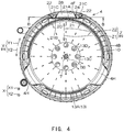
- Fig. 4 is a sectional view in an A-A direction of Fig. 1 .
- the graphic representation of the aforementioned separating member 9 is omitted.
- the circumferential direction of the inner circumferential surface 4F of the washing tank 4 is hereinafter called circumferential direction Y
- a radial direction of the inner circumferential surface 4F is called the radial direction Z.
- Both the circumferential direction Y and the radial direction Z are directions along the horizontal direction H.
- the clockwise direction at the top view is called clockwise Y1
- the counterclockwise direction at the top view is called counterclockwise Y2.
- the radial direction Z one side facing the central shaft 7 is called a radial inner side Z1, and one side away from the central shaft 7 is called a radial outer side Z2.
- Water pumping paths 20 are installed on the inner circumferential surface 4F of the washing tank 4.
- the number of the water pumping paths 20 may be set randomly and may be single or multiple.
- three water pumping paths 20 of the same shape and the same size are installed at the inner circumferential surface 4F at a state of being distributed in the circumferential direction Y. It should be noted that in Fig. 4 , for convenience in description, only one water pumping path 20 is shown. A distance between every two adjacent water pumping paths 20 in the circumferential direction Y may be constant among all the water pumping paths 20 and may also be different according to different water pumping paths 20.
- the water pumping paths 20 are described below in detail by referring to the state of being installed at the washing tank 4.
- Each water pumping path 20 includes a main body part 21 made of resin.
- the main body part 21 is of a long-edge cover shape in the up-down direction X and is erected at the inner circumferential surface 4F (also referring to Fig. 1 ) of the washing tank 4 from the radial inner side Z1 at a vertical posture between the shock absorber 8 and the bottom wall 4C of the washing tank 4. Therefore, the main body part 21 has a back surface 21A opposed to the inner circumferential surface 4F of the washing tank 4 and a surface 21B disposed at an opposite side of the back surface 21A and facing the side of the central shaft 7.
- Fig. 5 and Fig. 6 are three-dimensional views illustrating the bottom 4D and the water pumping paths 20 of the washing tank 4 viewed from the upper side X1 at other viewpoints.
- two end portions of the main body part 21 in the circumferential direction Y respectively form bending portions 21C covering almost a whole area in the up-down direction X and bent towards the radial outer side Z2.
- Each bending portion 21C is formed in a manner of inclining relative to the circumferential direction Y and the radial direction Z, and the surface 21B of each bending portion 21C is at a state of facing the circumferential direction Y.
- the upper end portion 21D of the main body part 21 is bent towards the radial outer side Z2 and erected between the bending portions 21C at two sides.
- a lengthwise slit-shaped outlet 22 is formed at each bending portion 21C.
- the outlets 22 are arranged at two sides in the circumferential direction Y in the water pumping path 20.
- the outlets 22, for example, are arranged at each bending portion 21C side by side in the up-down direction X, and penetrate through the bending portions 21C in a manner of being exposed out of the back surface 21A and the surface 21B of the main body part 21.
- Each outlet 22 is arranged at the surface 21B of the bending portion 21C in a manner of facing the circumferential direction Y (also referring to Fig. 4 ).
- Each bending portion 21c is respectively integrally provided with a projection 23 extending towards the radial inner side Z1 and disposed between the upper and the lower adjacent outlets 22, at upper side X1 of the outlet 22 disposed at the upper side X1 and at the lower side X2 of the outlet 22 disposed at the lower side X2.
- the projections 23 are protruded towards the radial inner side Z1 from the surface 21B of the main body part 21.
- a threaded hole 23A is formed at the end surface of the radial outer side Z2 of each projection 23.
- the threaded hole 23A is also formed at the upper end portion 21D of the main body part 21.
- the threaded hole 23A is provided with a bolt (not shown) inserted from the radial outer side Z2 of the washing tank 4 in order to fix the water pumping path 20 at the washing tank 4.
- the threaded hole 23A is configured at the outer side closer to the circumferential direction Y than the outlet 22.
- ribs 21E protruding towards the radial outer side Z2 and linearly extending along the up-down direction X are respectively arranged one by one at two sides in the circumferential direction Y.
- the ribs 21E are of a plate shape which is relatively thin in the circumferential direction Y and extend towards the lower side X2 from the upper end portion 21D between the threaded hole 23A and the outlet 22 in the circumferential direction Y at each bending portion 21C.
- the ribs 21E are configured adjacent to the outlets 22 in a manner of banding the outer sides of the outlets 22 in the circumferential direction Y.
- Fig. 7 is a sectional view in a B-B direction of Fig. 4 .
- the lower end portion of the back surface 21A of the main body part 21 is integrally provided with an inlet member 24.
- the inlet member 24 is formed into a generally U-shaped plate shape (referring to Fig. 4 ) bent to be bulged towards the radial outer side Z2 when in top view.
- the width of the inlet member 24 in the circumferential direction Y is gradually narrowed towards the upper side X1.
- a lower portion 24A of the inlet member 24 is configured in a manner of more protruding downwards than the lower end of the main body part 21.
- An area entrapped by the generally-U-shaped lower portion 24A is an inlet 25 of the water pumping path 20.
- the inlet 25 is disposed at a position lower than the outlet 22 in the water pumping path 20.
- all outlets 22 are configured in a manner of biasing towards the circumferential direction Y relative to the center 25A of the inlet 25 in the circumferential direction Y.
- Depressions 4H (also referring to Fig. 5 ) having the number same with that of the water pumping paths 20 and recessed towards the radial outer side Z2 from the second space 12 with the impeller 13 are formed at the bottom wall 4C of the washing tank 4, and the depressions 4H can receive the inlet member 24 of any water pumping path 20. Therefore, at the state where the water pumping path 20 is already installed at the washing tank 4, the inlet 25 is disposed at the bottom 4D of the washing tank 4 and is at a state of being communicated with the second space 12 from the radial outer side Z2 (referring to Fig. 5 ).
- the back surface 21A of the main body part 21 is provided with a flow path 26.
- the flow path 26 is a space (also referring to Fig. 6 ) with an upper long edge and a lower long edge entrapped by the ribs 21E at two sides of the back surface 21A in the circumferential direction Y and is blocked by the inner circumferential surface 4F of the washing tank 4 from the radial outer side Z2.
- the lower end portion of the flow path 26 is entrapped by the back surface 21A of the main body part 21 and the inlet member 25 from the radial direction Z.
- the flow path 26 extends towards the upper side X1 to the outlet 22 from the inlet 25 in a manner of being communicated with the inlet 25 at the lower end and being communicated with the outlet 22 at the upper end.
- the upper portion of the back surface 21A of the main body part 21 is integrally provided with a blocking member 27 (also referring to Fig. 6 ).
- the blocking member 27 is formed into a plate shape which is relatively thin in the up-down direction X, extends towards the horizontal direction H and is erected between the ribs 21E at two sides of the main body part 21.
- the blocking member 27 is disposed at the upper end of the uppermost outlet 22 of each bending portion 21C.
- a lower surface 27A of the blocking member 27 is flat in the horizontal direction H, and the upper end of the flow path 26 is at a state of being blocked by the lower surface 27A from the upper side X1. Therefore, the upper end of the flow path 26 is a tail end.
- the upper end of the flow path 26 extending towards the upper side X1 to the outlet 22 from the inlet 25 is blocked by the blocking member 27 as shown in Fig. 7 , and the outlet 22 is of a lengthwise slit shape. Therefore, the water is sprinkled after the direction of the water which is pumped from the inlet 25 and drawn through the flow path 26 is changed by the blocking member 27, and after the flow rate of the water is increased through the lengthwise slender outlet 22.
- the water running into the blocking member 27 arrives at the upstream side outlet 22B after being downward obliquely bounced towards the counterclockwise direction Y2 by the blocking member 27.
- the blocking member 27 is disposed at the upper end of the outlet 22, so that the flowing direction of the water drawn through the flow path 26 can be changed before arriving at the upstream side outlet 22B.
- the water arriving at the upstream side outlet 22B is downward obliquely injected strongly towards the counterclockwise direction Y2 from the upstream side outlet 22B at a state where the flow rate is increased by the upstream side outlet 22B.
- the phenomenon completely opposite to that in the case where the impeller 13 rotates towards the clockwise direction Y1 may occur.
- the positions of the downstream side outlet 22A and the upstream side outlet 22B in the circumferential direction Y are interchanged, and the water drawn from the flow path 26 is upward obliquely injected strongly towards the counterclockwise direction Y2 from the downstream side outlet 22A, and is downward obliquely injected strongly towards the clockwise direction Y1 from the upstream side outlet 22B (not shown).
- the water pumping paths 20 with the outlets 22 arranged at two sides in the circumferential direction Y can change the orientation of the water injected from the outlet 22 through the outlets 22 at one side and the outlets 22 at the other side in the outlets at two sides corresponding to the rotating direction of the washing tank 4. Therefore, the water sprinkled from various outlets 22 is injected in various directions to form a band shape scattered in the longitudinal direction, and strongly sprinkled onto the washings S in the washing tank 4, so that the washings S are cleaned while being stirred in various directions through the complexly varied strong water flow. Therefore, the cleaning force can be increased. Furthermore, compared with a cross outlet, the lengthwise outlet 22 can make the flow of water injected from the outlet 22 complex.
- the outlet 22 is arranged in a manner of biasing towards the circumferential direction Y relative to the center 25A of the inlet 25.
- the water flow pumped from the inlet 25 and drawn through the flow path 26 is changed, and the drawn water is strongly injected into the washing tank 4 from the outlet 22.
- the washings S sprinkled with the water can be effectively cleaned through the sufficient stirring.
- the water drawn through the flow path 26 can be injected towards the circumferential direction Y from the outlets 22.
- the washings S in the washing tank 4 can be cleaned while being stirred in a way of rotating towards the circumferential direction Y through the water injected towards the circumferential direction Y.
- the impeller 13 is arranged at the bottom 4D of the washing tank 4 in a manner of being separated from the washings S.
- the internal space 10 of the washing tank 4 is divided by the separating member 9 into the first space 11 for configuring the washings S and the second space 120 for configuring the impeller 13, the impeller 13 can be reliably separated from the washings S. Therefore, even when the impeller 13 rotates for delivering the water, the washings S may not be abraded by the impeller 13, and the damage to the washings S can be prevented.
- the impeller 13 can rotate at a high speed, so that the power of the water drawn from the flow path 26 of the water pumping path 20 can be increased, so that the water is more strongly injected into the washing tank 4 from the outlets 22 so as to sufficiently stir the washings S.
- the second space 12 is a concave portion 4G with a narrow top and bottom formed at the bottom 4C of the washing tank 4, the first space 11 (the capacity of the washing S) at the upper side X1 can be maximized as far as possible.
- the washing machine 1 enables the washings to move violently so as to be cleaned through the strong and complex flow of the water injected from the water pumping path 20 of a simple structure rather than the existing impeller in the case where the washings S are not damaged.
- the washings S can be effectively cleaned while the damage to the washings S is prevented.
- the water in the washing tank 4 can be repeatedly used for washing after being circulated through the flow path 26 of the water pumping path 26, less water can be used for washing.
- Fig. 8 is a longitudinal sectional view illustrating an internal structure of a washing machine according to a first variation embodiment of the present invention. As shown in Fig. 8 , for convenience in description, the graphic representation of the aforementioned separating member 9 is omitted.
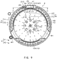
- Fig. 9 is a sectional view in a C-C direction of Fig. 8 .
- Fig. 10 is a sectional view in a D-D direction of Fig. 9 .
- each water pumping path 20 is provided with the outlets 22 at two sides in the circumferential direction Y
- the outlets 22 may also be arranged at a single side of the circumferential direction Y as shown in the first variation embodiment shown in Fig. 8 to Fig. 10 .
- the bending portion 21C at one side where the outlet 22 is omitted forms the inclined member 40 inclined relative to the up-down direction X in a manner of approaching the outlet 22 when viewed from the radial inner side Z1.
- outlets 22 are arranged at a single side in the circumferential direction Y in various water pumping paths 20, in the case of arranging multiple water pumping paths 20 side by side in the circumferential direction Y, the power loss of the water injected from the outlets 22 of the adjacent water pumping paths 20 due to the mutual collision can be prevented.
- the outlets 22 are required to be arranged at the same side.
- the flow path 26 of the water pumping path 26 is gradually narrowed from the inlet 25 to the outlet 22 through the inclined member 40.
- the flow rate of the water pumped from the inlet 25 and drawn through the flow path 26 may be higher when being closer to the outlet 22. Therefore, the drawn water can be more strongly injected into the washing tank 4 from the outlet 22.
- the washings S sprinkled with the water can be effectively cleaned through the sufficient stirring.
- the impeller 13 rotates towards the counterclockwise direction Y2.
- the outlet 22 is the aforementioned downstream side outlet 22A
- the water is upward obliquely injected strongly towards the counterclockwise direction Y2 from the downstream side outlet 22A (referring to the bold solid line arrow).
- the outlet 22 shown in Fig. 10 is the aforementioned upstream side outlet 22B
- the water drawn through the flow path 26 is downward obliquely injected strongly towards the counterclockwise direction Y2 from the upstream side outlet 22B when running into the blocking member 27 (referring to the bold dotted line arrow).
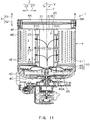
- Fig. 11 is a longitudinal sectional view illustrating an internal structure of a washing machine according to a second variation embodiment of the present invention.
- the partition member 9 may also be omitted, and a conventional pulsator 45 is configured to replace the impeller 13.
- a back blade 45A equivalent to the blades 13B of the impeller 13 is arranged below the pulsator 45, and when the pulsator 45 rotates, the back blade 45A delivers the water stored in the washing tank 4 into the inlet 25 of the water pumping path 20.
- the pulsator 45 Since the pulsator 45 contacts the washings S in the washing tank 4, in order to avoid the damage to the washings S, the pulsator 45 rotates preferably at a lower speed than the impeller 13. In this case, besides the soft stirring by the pulsator 45 rotating at a low speed, the washings S are also stirred through the power of the water (referring to the bold solid line) injected from the water pumping path 20. Thus, the washings S can be effectively cleaned while the damage to the washings S caused by the pulsator 45 is prevented.
- the outlets 22 may also be arranged at two sides of the water pumping path 20.
- the main body part 21 of the water pumping path 20 is of a cover shape, and the flow path 26 is a space divided into the back surface 21A of the main body part 21, a pair of ribs 21E of the back surface 21A, and the inner circumferential surface 4F of the washing tank 4.
- the flow path 26 is collectively formed by the water pumping path 20 and the inner circumferential surface 4F of the washing tank 4.
- the main body part 21 may also be a hollow body, and the hollow portion forms the flow path 26, so that the structure of the flow path 26 is formed independently by the water pumping path 20.
Landscapes
- Engineering & Computer Science (AREA)
- Textile Engineering (AREA)
- Detail Structures Of Washing Machines And Dryers (AREA)
- Cleaning By Liquid Or Steam (AREA)
- Main Body Construction Of Washing Machines And Laundry Dryers (AREA)
- Accessory Of Washing/Drying Machine, Commercial Washing/Drying Machine, Other Washing/Drying Machine (AREA)
Abstract
Description
- The present invention relates to a washing machine.
- In a washing machine described in the following
patent literature 1, washing blades are arranged at a bottom of an inner tank for receiving washings in a freely rotating manner, and an inner tank shell and a passage shell are arranged inside the inner tank. When the washing blades rotate, washing water is drawn through a water passage of the inner tank shell and a water passage of the passage shell and then sprayed onto the washings inside the inner tank. Thus, the washings are washed. - In a washing machine described in the following
patent literature 1, an impeller is arranged at an inner bottom of a washing and dehydrating tank, and a net for storing the washings is arranged in a position higher than the middle of the height direction in the washing and dehydrating tank. -
- Patent literature 1: Japanese Laid-Open Patent Publication No.
8-309090 - Patent literature 2: Japanese Laid-Open Patent Publication No.
10-235076 - The washing machine of the
patent literature 1 may have the problem that the washings are damaged due to the friction of the rotating washing blades on the washings. Furthermore, the structure for only sprinkling the drawn washing water onto the washings has a limitation on improving the cleaning force of the washings. - The washing machine of the
patent literature 2 separates the washings from the impeller by placing the washings on the net for storing the washings. Thus, the problem that the washings are damaged due to the friction of the rotating impeller on the washings can be eliminated. However, since only a region above the net for storing the washings in the washing and dehydrating tank can receive the washings, the capacity of the washing and dehydrating tank is reduced. In this case, since the washings cannot be sufficiently stirred in the washing and dehydrating tank, there is a limitation on improving the cleaning force of the washings. - The present invention is accomplished based on this background, and an objective of the present invention is to provide a washing machine which can prevent the damage to the washings and also can improve the cleaning force.
- The present invention relates to a washing machine, which is characterized by including: a washing tank for receiving washings and storing water; a water pumping path having an inlet disposed at a bottom of the washing tank, a lengthwise slit-shaped outlet disposed at a position higher than the inlet, and a flow path extending upwards from the inlet to the outlet, for pumping water stored in the washing tank from the inlet and spraying the water drawn through the flow path into the washing tank from the outlets; blocking members arranged at the water pumping path, for blocking an upper end of the flow path; and an impeller, arranged at the bottom of the washing tank in a way of being separated from washings, for delivering the water stored in the washing tank into the inlet through rotation.
- Furthermore, the present invention is characterized by including a separating member, which is arranged at the bottom of the washing tank, for dividing an internal space of the washing tank into a first space for configuring washings and a second space for configuring the impeller.
- Furthermore, the present invention is characterized in that the blocking member is disposed at an upper end of the outlet.
- Furthermore, the present invention is characterized in that the washing tank is a cylindrical washing tank having an axis extending longitudinally, and at each water pumping path, the outlets are biased towards a circumferential direction relative to a center of the inlet in the circumferential direction of the washing tank.
- Furthermore, the present invention is characterized in that the outlets are arranged in a manner of facing the circumferential direction.
- Furthermore, the present invention is characterized in that the outlets are arranged at two sides in the circumferential direction in the water pumping path.
- Furthermore, the present invention is characterized in that the outlets are arranged at a single side in the circumferential direction in the water pumping path, and the present invention includes an inclined member, which is inclined in a manner of approaching the outlets, so that the flow path is gradually narrowed from the inlet to the outlets
- According to the present invention, the impeller for delivering the water stored in the washing tank into the inlet of the water pumping path is arranged at the bottom of the washing tank in a manner of being separated from the washings. Therefore, even when the impeller rotates for delivering the water, the washings may not be abraded by the impeller, and the damage to the washings can be prevented.
- At the water pumping path, the upper end of the flow path extending upwards from the inlet to the outlet is blocked by the blocking member, and the outlet is in the lengthwise slit shape. Therefore, after the direction of the water which is pumped from the inlet and drawn through the flow path is changed by the blocking member, and after the flow rate of the water is increased through the lengthwise slender outlet, the water is injected. Thus, the water injected from the outlets is injected in various directions to form a band shape scattered in the longitudinal direction and is strongly sprinkled onto the washings in the washing tank, so that the washings are cleaned while being stirred in various directions. Therefore, the cleaning force is increased.
- Furthermore, according to the present invention, an internal space of the washing tank is divided by the separating member into a first space for configuring the washings and a second space for configuring the impeller, so that the impeller can be reliably separated from the washings.
- Furthermore, according to the present invention, since the blocking member is disposed at the upper end of the outlet, the flowing direction of the water drawn through the flow path can be changed before reaching the outlet. Thus, the water sprinkled from the outlets can be injected in various directions.
- Furthermore, according to the present invention, at the water pumping path, the outlet is arranged in a manner of biasing towards the circumferential direction relative to the center of the inlet in the circumferential direction of the washing tank. Thus, the water flow pumped from the inlet and drawn through the flow path can be changed, and the drawn water can be strongly injected into the washing tank from the outlets. Therefore, the washings sprinkled with water can be effectively cleaned through sufficient stirring.
- Furthermore, according to the present invention, since the outlets are arranged in a manner of facing the circumferential direction, the water drawn through the flow path can be injected in the circumferential direction from the outlets. Thus, the water injected in the circumferential direction can be used for cleaning the washings while the washings in the washing tank are stirred in a manner of rotating towards the circumferential direction.
- Furthermore, according to the present invention, since the outlets are arranged at two sides in the circumferential direction of the water pumping path, the orientation of the water injected from the outlets can be changed from the outlets at one side and the outlets at the other side in the outlets at two sides relative to the rotating direction of the washing tank. Thus, at the water pumping path, since the water injected from each outlet can be sprinkled towards the washings in the washing tank in various directions, the washings can be effectively cleaned through the sufficient stirring in various directions.
- Furthermore, according to the present invention, since the outlets are arranged at a single side in the circumferential direction in the water pumping path, in the case of arranging multiple water pumping paths side by side in the circumferential direction, the power loss of the water injected from the outlets of the adjacent water pumping paths due to the mutual collision can be prevented.
- The flow path of the water pumping path is gradually narrowed from the inlet to the outlet through the inclined member. Thus, the flow rate of the water pumped from the inlet and drawn through the flow path can be increased along the direction towards the outlets. Therefore, the drawn water can be more strongly injected into the washing tank from the outlets. Thus, the washings sprinkled with the water can be effectively cleaned through the sufficient stirring.
-
-
Fig. 1 is a longitudinal sectional view illustrating an internal structure of a washing machine according to an embodiment of the present invention. -
Fig. 2 is a three-dimensional top view illustrating an impeller included in a washing machine. -
Fig. 3 is a three-dimensional bottom view illustrating an impeller. -
Fig. 4 is a sectional view in an A-A direction ofFig. 1 . -
Fig. 5 is a three-dimensional top view illustrating a bottom and a water pumping path of a washing tank of a washing machine. -
Fig. 6 is a three-dimensional top view illustrating a bottom and a water pumping path of a washing tank from a viewpoint different fromFig. 5 . -
Fig. 7 is a sectional view in a B-B direction ofFig. 4 . -
Fig. 8 is a longitudinal sectional view illustrating an internal structure of a washing machine according to a first variation embodiment of the present invention. -
Fig. 9 is a sectional view in a C-C direction ofFig. 8 . -
Fig. 10 is a sectional view in a D-D direction ofFig. 9 . -
Fig. 11 is a longitudinal sectional view illustrating an internal structure of a washing machine according to a second variation embodiment of the present invention. - Embodiments of the present invention are described below with reference to the drawings.
-
Fig. 1 is a longitudinal sectional view illustrating an internal structure of awashing machine 1 according to an embodiment of the present invention. - Firstly, an outline of the
washing machine 1 is described with an up-down direction X ofFig. 1 as a reference. In the up-down direction X as a vertical direction, an upper side is called an upper side X1, and a lower side is called a lower side X2. Furthermore, thewashing machine 1 also includes a washing and drying machine with a function of drying washings S. - The
washing machine 1 includes ahousing 2, anouter tank 3, awashing tank 4 and amotor 5. - The
housing 2 is in a box shape. Theouter tank 3, thewashing tank 4 and themotor 5 are arranged in thehousing 2. - The
outer tank 3 is made of, for example, resin and formed in a cylindrical shape with a bottom. Theouter tank 3 has acircumferential wall 3B which is in a generally-cylindrical shape with anopening portion 3A at the upper end, and a disc-shapedbottom wall 3C blocking a hollow portion of thecircumferential wall 3B from the lower side X2. Theopening portion 3A is opened and closed through acover 6 connected with thecircumferential wall 3B. Water such as tap water, bath water, a liquid dissolved with detergents and the like can be stored in theouter tank 3. - The
washing tank 4 is formed in a cylindrical shape with a bottom, is one circle smaller than the outer tank and receives the washings S. Thewashing tank 4 has acircumferential wall 4B which is in a generally-cylindrical shape with anaccess opening 4A at the upper end, and a disc-shapedbottom wall 4C blocking a hollow portion of thecircumferential wall 4B from the lower side X2. For example, thecircumferential wall 4B is made of metal, a center portion of thebottom wall 4C is made of metal, and a peripheral portion of the bottom wall is made of resin. Thebottom wall 4C and the lower end portion of thecircumferential wall 4B which is connected with thebottom wall 4C form a bottom 4D of thewashing tank 4. Thewashing tank 4 is coaxially received in theouter tank 3. Thewashing tank 4 at a state of being received in theouter tank 3 can rotate around acentral shaft 7 which is used as an axis of the washing tank and extends to the up-down direction X. Thiswashing machine 1 is a longitudinal-type washing machine with thewashing tank 4 arranged in the longitudinal direction. - The
access opening 4A is communicated with theopening portion 3A from the lower side X2, and theopening portion 3A and theaccess opening 4A are collectively opened and closed through thecover 6. A user of thewashing machine 1 can take the washings S into and out of thewashing tank 4 through the openedaccess opening 4A. Thecircumferential wall 4B and thebottom wall 4C are respectively provided with a throughhole 4E, and the water in theouter tank 3 can be circulated between theouter tank 3 and thewashing tank 4 via the throughholes 4E. Thus, thewashing tank 4 stores the water at a water level equal to a water level of theouter tank 3. - An
annular shock absorber 8 is installed at the upper end portion of an innercircumferential surface 4F of thecircumferential wall 4B. Theshock absorber 8 is a member reducing the vibration of therotating washing tank 4, and the liquid for facilitating the shock absorption is received in ahole 8A inside theshock absorber 8. - A
concave portion 4G which is sunken downwards is formed at the upper surface of thebottom wall 4C. Theconcave portion 4G is a cylindrical space with a flat top and a flat bottom in a coaxial state with thebottom wall 4C. Thewashing tank 4 includes a separatingmember 9 arranged at the bottom 4D. The separatingmember 9 is a disc-shaped cover blocking theconcave portion 4G from the top, and a plurality of throughholes 9A are intensively formed at a center side of the cover. Aninternal space 10 of thewashing tank 4 is divided by the separatingmember 9 into afirst space 11 communicated with theaccess opening 4A and configured with the washings S and asecond space 12 equivalent to theconcave portion 4G. - The
motor 5 is arranged at the lower side X2 of thebottom wall 3C of theouter tank 3 in thehousing 2. An output shaft of themotor 5 is divided into a tubularfirst output shaft 5A extending towards the upper side X1 and asecond output shaft 5B which is sufficiently inserted into thefirst output shaft 5A. Themotor 5 selects one of thefirst output shaft 5A and thesecond output shaft 5B to output a driving force through aspeed changing mechanism 15. - The
first output shaft 5A extends towards the upper side X1 and successively penetrates through the circle center of thebottom wall 3C and the circle center of thebottom wall 4C of thewashing tank 4. Thefirst output shaft 5A has aflange portion 5C which is protruded between thebottom wall 3C and thebottom wall 4C in a brim manner, and is fixed to thebottom wall 4C through theflange portion 5C so as to realize connection with thewashing tank 4. When themotor 5 is driven and transfers the driving force to thefirst output shaft 5A, thewashing tank 4 rotates. - An
impeller 13 is installed at the upper end, which is more protruded to the upper side X1 than theflange portion 5C, of thesecond output shaft 5B. -
Fig. 2 is a three-dimensional view illustrating theimpeller 13 viewed from the upper side X1, andFig. 3 is a three-dimensional view illustrating theimpeller 13 viewed from the lower side X2. - Referring to
Fig. 2 and Fig. 3 , theimpeller 13 integrally includes a pair ofdiscs 13A which are coaxially arranged in parallel in the vertical direction and a plurality ofblades 13B which are erected between the pair ofdiscs 13A and extend in a radiating manner by adopting the circle center of thedisc 13A as a reference. In the pair ofdiscs 13A, a circular throughhole 13C (referring toFig. 2 ) penetrating through the center portion of thedisc 13A at the upper side X2 is formed thereon, and a plurality of circular throughholes 13D (referring toFig. 3 ) surrounding the circle center portion are formed at thecircular plate 13A at the lower side X2. Eachblade 13B linearly extends towards the peripheral edge of thedisc 13A from the edge of the throughhole 13C. - Referring to
Fig. 1 , theimpeller 13 is configured at the second space (the aforementionedconcave portion 4G of thebottom wall 4C) of thebottom wall 4D of thewashing tank 4. Since thesecond space 12 is at a state of being separated from thefirst space 11 of the upper side X1 for configuring the washings S through the separatingmember 9, theimpeller 13 is arranged at the bottom 4D in a manner of being separated from the washings S. The water stored in thewashing tank 4 also exists between the pair ofdiscs 13A via the throughhole 9A of the separatingmember 9 and the throughholes discs 13A of theimpeller 13. - The upper end portion of the
second output shaft 5B of themotor 5 is installed at the circle center portion of thedisc 13A at the lower side X2. When themotor 5 is driven and transfers the driving force to thesecond output shaft 5B, theimpeller 13 rotates. When theimpeller 13 rotates, thewashing tank 4 is at a stopped state. -
Fig. 4 is a sectional view in an A-A direction ofFig. 1 . As shown inFig. 4 , for convenience in description, the graphic representation of theaforementioned separating member 9 is omitted. Referring toFig. 4 , the circumferential direction of the innercircumferential surface 4F of thewashing tank 4 is hereinafter called circumferential direction Y, and a radial direction of the innercircumferential surface 4F is called the radial direction Z. Both the circumferential direction Y and the radial direction Z are directions along the horizontal direction H. In the circumferential direction Y, the clockwise direction at the top view is called clockwise Y1, and the counterclockwise direction at the top view is called counterclockwise Y2. In the radial direction Z, one side facing thecentral shaft 7 is called a radial inner side Z1, and one side away from thecentral shaft 7 is called a radial outer side Z2. -
Water pumping paths 20 are installed on the innercircumferential surface 4F of thewashing tank 4. The number of thewater pumping paths 20 may be set randomly and may be single or multiple. In the present embodiment, threewater pumping paths 20 of the same shape and the same size are installed at the innercircumferential surface 4F at a state of being distributed in the circumferential direction Y. It should be noted that inFig. 4 , for convenience in description, only onewater pumping path 20 is shown. A distance between every two adjacentwater pumping paths 20 in the circumferential direction Y may be constant among all thewater pumping paths 20 and may also be different according to differentwater pumping paths 20. Thewater pumping paths 20 are described below in detail by referring to the state of being installed at thewashing tank 4. - Each
water pumping path 20 includes amain body part 21 made of resin. Themain body part 21 is of a long-edge cover shape in the up-down direction X and is erected at the innercircumferential surface 4F (also referring toFig. 1 ) of thewashing tank 4 from the radial inner side Z1 at a vertical posture between theshock absorber 8 and thebottom wall 4C of thewashing tank 4. Therefore, themain body part 21 has aback surface 21A opposed to the innercircumferential surface 4F of thewashing tank 4 and asurface 21B disposed at an opposite side of theback surface 21A and facing the side of thecentral shaft 7. -
Fig. 5 andFig. 6 are three-dimensional views illustrating the bottom 4D and thewater pumping paths 20 of thewashing tank 4 viewed from the upper side X1 at other viewpoints. Referring toFig. 5 andFig. 6 , two end portions of themain body part 21 in the circumferential direction Y respectively form bendingportions 21C covering almost a whole area in the up-down direction X and bent towards the radial outer side Z2. Each bendingportion 21C is formed in a manner of inclining relative to the circumferential direction Y and the radial direction Z, and thesurface 21B of each bendingportion 21C is at a state of facing the circumferential direction Y. Furthermore, theupper end portion 21D of themain body part 21 is bent towards the radial outer side Z2 and erected between the bendingportions 21C at two sides. - A lengthwise slit-shaped
outlet 22 is formed at each bendingportion 21C. In other words, theoutlets 22 are arranged at two sides in the circumferential direction Y in thewater pumping path 20. Theoutlets 22, for example, are arranged at each bendingportion 21C side by side in the up-down direction X, and penetrate through the bendingportions 21C in a manner of being exposed out of theback surface 21A and thesurface 21B of themain body part 21. Eachoutlet 22 is arranged at thesurface 21B of the bendingportion 21C in a manner of facing the circumferential direction Y (also referring toFig. 4 ). - Each bending portion 21c is respectively integrally provided with a
projection 23 extending towards the radial inner side Z1 and disposed between the upper and the loweradjacent outlets 22, at upper side X1 of theoutlet 22 disposed at the upper side X1 and at the lower side X2 of theoutlet 22 disposed at the lower side X2. Theprojections 23 are protruded towards the radial inner side Z1 from thesurface 21B of themain body part 21. As shown inFig. 6 , a threadedhole 23A is formed at the end surface of the radial outer side Z2 of eachprojection 23. The threadedhole 23A is also formed at theupper end portion 21D of themain body part 21. The threadedhole 23A is provided with a bolt (not shown) inserted from the radial outer side Z2 of thewashing tank 4 in order to fix thewater pumping path 20 at thewashing tank 4. - At the
back surface 21A of each bendingportion 21C, the threadedhole 23A is configured at the outer side closer to the circumferential direction Y than theoutlet 22. At theback surface 21A of themain body part 21,ribs 21E protruding towards the radial outer side Z2 and linearly extending along the up-down direction X are respectively arranged one by one at two sides in the circumferential direction Y. Theribs 21E are of a plate shape which is relatively thin in the circumferential direction Y and extend towards the lower side X2 from theupper end portion 21D between the threadedhole 23A and theoutlet 22 in the circumferential direction Y at each bendingportion 21C. Theribs 21E are configured adjacent to theoutlets 22 in a manner of banding the outer sides of theoutlets 22 in the circumferential direction Y. -
Fig. 7 is a sectional view in a B-B direction ofFig. 4 . Referring toFig. 7 , the lower end portion of theback surface 21A of themain body part 21 is integrally provided with aninlet member 24. Theinlet member 24 is formed into a generally U-shaped plate shape (referring toFig. 4 ) bent to be bulged towards the radial outer side Z2 when in top view. The width of theinlet member 24 in the circumferential direction Y is gradually narrowed towards the upper side X1. Alower portion 24A of theinlet member 24 is configured in a manner of more protruding downwards than the lower end of themain body part 21. An area entrapped by the generally-U-shapedlower portion 24A is aninlet 25 of thewater pumping path 20. Theinlet 25 is disposed at a position lower than theoutlet 22 in thewater pumping path 20. Furthermore, at eachwater pumping path 20, alloutlets 22 are configured in a manner of biasing towards the circumferential direction Y relative to thecenter 25A of theinlet 25 in the circumferential direction Y. -
Depressions 4H (also referring toFig. 5 ) having the number same with that of thewater pumping paths 20 and recessed towards the radial outer side Z2 from thesecond space 12 with theimpeller 13 are formed at thebottom wall 4C of thewashing tank 4, and thedepressions 4H can receive theinlet member 24 of anywater pumping path 20. Therefore, at the state where thewater pumping path 20 is already installed at thewashing tank 4, theinlet 25 is disposed at the bottom 4D of thewashing tank 4 and is at a state of being communicated with thesecond space 12 from the radial outer side Z2 (referring toFig. 5 ). - The
back surface 21A of themain body part 21 is provided with aflow path 26. Theflow path 26 is a space (also referring toFig. 6 ) with an upper long edge and a lower long edge entrapped by theribs 21E at two sides of theback surface 21A in the circumferential direction Y and is blocked by the innercircumferential surface 4F of thewashing tank 4 from the radial outer side Z2. The lower end portion of theflow path 26 is entrapped by theback surface 21A of themain body part 21 and theinlet member 25 from the radial direction Z. Theflow path 26 extends towards the upper side X1 to theoutlet 22 from theinlet 25 in a manner of being communicated with theinlet 25 at the lower end and being communicated with theoutlet 22 at the upper end. - The upper portion of the
back surface 21A of themain body part 21 is integrally provided with a blocking member 27 (also referring toFig. 6 ). The blockingmember 27 is formed into a plate shape which is relatively thin in the up-down direction X, extends towards the horizontal direction H and is erected between theribs 21E at two sides of themain body part 21. The blockingmember 27 is disposed at the upper end of theuppermost outlet 22 of each bendingportion 21C. Alower surface 27A of the blockingmember 27 is flat in the horizontal direction H, and the upper end of theflow path 26 is at a state of being blocked by thelower surface 27A from the upper side X1. Therefore, the upper end of theflow path 26 is a tail end. - Referring to
Fig. 1 , when theimpeller 13 rotates, the water stored at the bottom 4D of thewashing tank 4 is delivered into theinlet 25 of eachwater pumping path 20 through theblades 13B of theimpeller 13 and pumped into theflow path 26 from theinlet 25. As shown by a bold line arrow, the water pumped into theflow path 26 is drawn to theoutlet 22 of the upper side X1 through theflow path 26 and then injected into thewashing tank 4 from eachoutlet 22. - As described above, in the
water pumping path 20, the upper end of theflow path 26 extending towards the upper side X1 to theoutlet 22 from theinlet 25 is blocked by the blockingmember 27 as shown inFig. 7 , and theoutlet 22 is of a lengthwise slit shape. Therefore, the water is sprinkled after the direction of the water which is pumped from theinlet 25 and drawn through theflow path 26 is changed by the blockingmember 27, and after the flow rate of the water is increased through the lengthwiseslender outlet 22. - From the view of the rotating direction of the
impeller 13, for theoutlets 22 at two sides of thewater pumping path 20 in the circumferential direction Y, on the basis that theoutlet 22 at the downstream side is called adownstream side outlet 22A and theoutlet 22 at the upstream side is called an upstream side outlet 22B, the water injection phenomenon from theoutlet 22 is specifically described below. InFig. 7 , theoutlet 22 at the right side is used as thedownstream side outlet 22A, and theoutlet 22 at the left side is served as the upstream side outlet 22B. - In the case where the
impeller 13 rotates towards the clockwise direction Y1, the water drawn from theflow path 26 of thewater pumping path 20 rises while flowing towards the clockwise direction Y1. The water already reaching thedownstream side outlet 22A before arriving at the blockingmember 27 is strongly upward obliquely injected towards the clockwise direction Y1 from thedownstream side outlet 22A at the state where the flow rate is increased through thedownstream side outlet 22A (referring to the bold solid line arrow). - On the other hand, the water running into the blocking
member 27 arrives at the upstream side outlet 22B after being downward obliquely bounced towards the counterclockwise direction Y2 by the blockingmember 27. As described above, the blockingmember 27 is disposed at the upper end of theoutlet 22, so that the flowing direction of the water drawn through theflow path 26 can be changed before arriving at the upstream side outlet 22B. The water arriving at the upstream side outlet 22B is downward obliquely injected strongly towards the counterclockwise direction Y2 from the upstream side outlet 22B at a state where the flow rate is increased by the upstream side outlet 22B. - Furthermore, in the case where the
impeller 13 rotates towards the counterclockwise direction Y2, the phenomenon completely opposite to that in the case where theimpeller 13 rotates towards the clockwise direction Y1 may occur. In other words, the positions of thedownstream side outlet 22A and the upstream side outlet 22B in the circumferential direction Y are interchanged, and the water drawn from theflow path 26 is upward obliquely injected strongly towards the counterclockwise direction Y2 from thedownstream side outlet 22A, and is downward obliquely injected strongly towards the clockwise direction Y1 from the upstream side outlet 22B (not shown). - As described above, the
water pumping paths 20 with theoutlets 22 arranged at two sides in the circumferential direction Y can change the orientation of the water injected from theoutlet 22 through theoutlets 22 at one side and theoutlets 22 at the other side in the outlets at two sides corresponding to the rotating direction of thewashing tank 4. Therefore, the water sprinkled fromvarious outlets 22 is injected in various directions to form a band shape scattered in the longitudinal direction, and strongly sprinkled onto the washings S in thewashing tank 4, so that the washings S are cleaned while being stirred in various directions through the complexly varied strong water flow. Therefore, the cleaning force can be increased. Furthermore, compared with a cross outlet, thelengthwise outlet 22 can make the flow of water injected from theoutlet 22 complex. - As described above, at each
water pumping path 20, theoutlet 22 is arranged in a manner of biasing towards the circumferential direction Y relative to thecenter 25A of theinlet 25. Thus, the water flow pumped from theinlet 25 and drawn through theflow path 26 is changed, and the drawn water is strongly injected into thewashing tank 4 from theoutlet 22. Thus, the washings S sprinkled with the water can be effectively cleaned through the sufficient stirring. - Since all the
outlets 22 are configured towards the circumferential direction Y, the water drawn through theflow path 26 can be injected towards the circumferential direction Y from theoutlets 22. Thus, the washings S in thewashing tank 4 can be cleaned while being stirred in a way of rotating towards the circumferential direction Y through the water injected towards the circumferential direction Y. - As described above, in the
washing machine 1, as shown inFig. 1 , theimpeller 13 is arranged at the bottom 4D of thewashing tank 4 in a manner of being separated from the washings S. Particularly, since theinternal space 10 of thewashing tank 4 is divided by the separatingmember 9 into thefirst space 11 for configuring the washings S and the second space 120 for configuring theimpeller 13, theimpeller 13 can be reliably separated from the washings S. Therefore, even when theimpeller 13 rotates for delivering the water, the washings S may not be abraded by theimpeller 13, and the damage to the washings S can be prevented. - Furthermore, in the structure of separating the
impeller 13 from the washings S through the separatingmember 9, since theimpeller 13 can rotate at a high speed, the power of the water drawn from theflow path 26 of thewater pumping path 20 can be increased, so that the water is more strongly injected into thewashing tank 4 from theoutlets 22 so as to sufficiently stir the washings S. Further, since thesecond space 12 is aconcave portion 4G with a narrow top and bottom formed at the bottom 4C of thewashing tank 4, the first space 11 (the capacity of the washing S) at the upper side X1 can be maximized as far as possible. - As described above, the
washing machine 1 enables the washings to move violently so as to be cleaned through the strong and complex flow of the water injected from thewater pumping path 20 of a simple structure rather than the existing impeller in the case where the washings S are not damaged. Thus, the washings S can be effectively cleaned while the damage to the washings S is prevented. Furthermore, since the water in thewashing tank 4 can be repeatedly used for washing after being circulated through theflow path 26 of thewater pumping path 26, less water can be used for washing. - The present invention is not limited to the embodiments described above, and various changes can be made to the present invention within the described scope of claims.
-
Fig. 8 is a longitudinal sectional view illustrating an internal structure of a washing machine according to a first variation embodiment of the present invention. As shown inFig. 8 , for convenience in description, the graphic representation of theaforementioned separating member 9 is omitted.Fig. 9 is a sectional view in a C-C direction ofFig. 8 .Fig. 10 is a sectional view in a D-D direction ofFig. 9 . - For example, in the aforementioned embodiments, although each
water pumping path 20 is provided with theoutlets 22 at two sides in the circumferential direction Y, theoutlets 22 may also be arranged at a single side of the circumferential direction Y as shown in the first variation embodiment shown inFig. 8 to Fig. 10 . In this case, at themain body part 21 of thewater pumping path 20, the bendingportion 21C at one side where theoutlet 22 is omitted forms theinclined member 40 inclined relative to the up-down direction X in a manner of approaching theoutlet 22 when viewed from the radial inner side Z1. - Since the
outlets 22 are arranged at a single side in the circumferential direction Y in variouswater pumping paths 20, in the case of arranging multiplewater pumping paths 20 side by side in the circumferential direction Y, the power loss of the water injected from theoutlets 22 of the adjacentwater pumping paths 20 due to the mutual collision can be prevented. Of course, at this time, at eachwater pumping path 20, theoutlets 22 are required to be arranged at the same side. - As shown in
Fig. 10 , theflow path 26 of thewater pumping path 26 is gradually narrowed from theinlet 25 to theoutlet 22 through theinclined member 40. Thus, the flow rate of the water pumped from theinlet 25 and drawn through theflow path 26 may be higher when being closer to theoutlet 22. Therefore, the drawn water can be more strongly injected into thewashing tank 4 from theoutlet 22. Thus, the washings S sprinkled with the water can be effectively cleaned through the sufficient stirring. - Specifically, in
Fig. 10 , theimpeller 13 rotates towards the counterclockwise direction Y2. In the case where theoutlet 22 is the aforementioneddownstream side outlet 22A, before the water drawn through theflow path 26 runs into the blockingmember 27, the water is upward obliquely injected strongly towards the counterclockwise direction Y2 from thedownstream side outlet 22A (referring to the bold solid line arrow). On the other hand, in the case where theoutlet 22 shown inFig. 10 is the aforementioned upstream side outlet 22B, the water drawn through theflow path 26 is downward obliquely injected strongly towards the counterclockwise direction Y2 from the upstream side outlet 22B when running into the blocking member 27 (referring to the bold dotted line arrow). -
Fig. 11 is a longitudinal sectional view illustrating an internal structure of a washing machine according to a second variation embodiment of the present invention. As shown in the first variation embodiment, in the case where theoutlets 22 are arranged at the single side of thewater pumping path 20, as shown inFig. 11 , thepartition member 9 may also be omitted, and aconventional pulsator 45 is configured to replace theimpeller 13. In this case, aback blade 45A equivalent to theblades 13B of theimpeller 13 is arranged below thepulsator 45, and when thepulsator 45 rotates, theback blade 45A delivers the water stored in thewashing tank 4 into theinlet 25 of thewater pumping path 20. - Since the pulsator 45 contacts the washings S in the
washing tank 4, in order to avoid the damage to the washings S, thepulsator 45 rotates preferably at a lower speed than theimpeller 13. In this case, besides the soft stirring by thepulsator 45 rotating at a low speed, the washings S are also stirred through the power of the water (referring to the bold solid line) injected from thewater pumping path 20. Thus, the washings S can be effectively cleaned while the damage to the washings S caused by thepulsator 45 is prevented. Of course, as shown inFig. 11 , theoutlets 22 may also be arranged at two sides of thewater pumping path 20. - Furthermore, the
main body part 21 of thewater pumping path 20 is of a cover shape, and theflow path 26 is a space divided into theback surface 21A of themain body part 21, a pair ofribs 21E of theback surface 21A, and the innercircumferential surface 4F of thewashing tank 4. In other words, strictly speaking, theflow path 26 is collectively formed by thewater pumping path 20 and the innercircumferential surface 4F of thewashing tank 4. Alternatively, themain body part 21 may also be a hollow body, and the hollow portion forms theflow path 26, so that the structure of theflow path 26 is formed independently by thewater pumping path 20. - 1: Washing machine; 4: Washing tank; 4D: Bottom; 7: Central shaft; 9: Separating member; 10: Internal space; 11: First space; 12: Second space; 13: Impeller; 20: Water pumping path; 22: Outlet; 25: Inlet; 25A: Center, 26: Flow path; 27: Blocking member; 40: Inclined member; S: Washings; X1: Upper side; Y: Circumferential direction.
Claims (7)
- A washing machine, comprising:a washing tank, for receiving washings and storing water;a water pumping path, having an inlet disposed at a bottom of the washing tank, a lengthwise slit-shaped outlet disposed at a position higher than the inlet, and a flow path extending upwards from the inlet to the outlet, for pumping water stored in the washing tank from the inlet and spraying the water drawn through the flow path into the washing tank from the outlets;blocking member, arranged at the water pumping path, for blocking an upper end of the flow path; andan impeller, arranged at the bottom of the washing tank in a manner of being separated from washings, for delivering the water stored in the washing tank into the inlet through rotation.
- The washing machine according to claim 1, wherein
the washing machine comprises a separating member, which is arranged at the bottom of the washing tank, for dividing an internal space of the washing tank into a first space for configuring washings and a second space for configuring the impeller. - The washing machine according to claim 1 or 2, wherein
the blocking member is disposed at an upper end of the outlet. - The washing machine according to any one of claims 1-3, wherein
the washing tank is a cylindrical washing tank with an axis extending longitudinally, and
at the water pumping path, the outlets are arranged in a manner of biasing towards a circumferential direction relative to a center of the inlet in the circumferential direction of the washing tank. - The washing machine according to claim 4, wherein
the outlets are configured in a manner of facing the circumferential direction. - The washing machine according to claim 4 or 5, wherein
the outlets are arranged at two sides in the circumferential direction in the water pumping path. - The washing machine according to claim 4 or 5, wherein
the outlets are arranged at a single side in the circumferential direction in the water pumping path, and
the washing machine comprises an inclined member, which is inclined in a manner of approaching the outlets, so that the flow path is gradually narrowed from the inlet to the outlet.
Applications Claiming Priority (2)
| Application Number | Priority Date | Filing Date | Title |
|---|---|---|---|
| JP2014201555A JP2016067694A (en) | 2014-09-30 | 2014-09-30 | Washing machine |
| PCT/CN2015/090349 WO2016050157A1 (en) | 2014-09-30 | 2015-09-23 | Washing machine |
Publications (2)
| Publication Number | Publication Date |
|---|---|
| EP3202966A1 true EP3202966A1 (en) | 2017-08-09 |
| EP3202966A4 EP3202966A4 (en) | 2018-06-13 |
Family
ID=55629429
Family Applications (1)
| Application Number | Title | Priority Date | Filing Date |
|---|---|---|---|
| EP15846496.6A Withdrawn EP3202966A4 (en) | 2014-09-30 | 2015-09-23 | Washing machine |
Country Status (6)
| Country | Link |
|---|---|
| US (1) | US20170298550A1 (en) |
| EP (1) | EP3202966A4 (en) |
| JP (1) | JP2016067694A (en) |
| KR (1) | KR20170060151A (en) |
| CN (1) | CN106795677B (en) |
| WO (1) | WO2016050157A1 (en) |
Families Citing this family (4)
| Publication number | Priority date | Publication date | Assignee | Title |
|---|---|---|---|---|
| CN105887405A (en) * | 2016-06-03 | 2016-08-24 | 无锡小天鹅股份有限公司 | Impeller type washing machine |
| BR102017008941B1 (en) * | 2017-04-27 | 2022-12-27 | Electrolux Do Brasil S.A | WASHING MACHINE INCLUDING AN IMPELLER |
| CN109137360A (en) * | 2017-06-15 | 2019-01-04 | 无锡小天鹅股份有限公司 | The clothes washing method of washing machine |
| JP7454811B2 (en) * | 2019-12-26 | 2024-03-25 | 青島海爾洗衣机有限公司 | washing machine |
Family Cites Families (11)
| Publication number | Priority date | Publication date | Assignee | Title |
|---|---|---|---|---|
| US5509283A (en) * | 1993-12-14 | 1996-04-23 | Samsung Electronics Co., Ltd. | Clothes washer having water recirculation system |
| JPH0884887A (en) * | 1994-09-19 | 1996-04-02 | Matsushita Electric Ind Co Ltd | Washing machine |
| KR0125924Y1 (en) * | 1995-05-16 | 1999-04-15 | 구자홍 | washer |
| JP3823421B2 (en) * | 1997-03-03 | 2006-09-20 | 松下電器産業株式会社 | Washing machine |
| TW405001B (en) * | 1998-01-31 | 2000-09-11 | Samsung Electronics Co Ltd | Washing maching having a water guide for forming vertical and horizontal currents of wash water |
| KR100437791B1 (en) * | 2001-12-17 | 2004-06-30 | 엘지전자 주식회사 | Washing machine |
| CN2555274Y (en) * | 2002-06-27 | 2003-06-11 | 金羚电器有限公司 | Washing machine |
| CN2844179Y (en) * | 2005-07-27 | 2006-12-06 | Tcl家用电器(惠州)有限公司 | Automatic triple-dynamic corrugated washer |
| CN1916265A (en) * | 2006-08-30 | 2007-02-21 | 石宝华 | Versatile washing machine |
| TWI548793B (en) * | 2013-06-21 | 2016-09-11 | Toshiba Lifestyle Products & Services Corp | Washing machine |
| CN203700801U (en) * | 2013-12-06 | 2014-07-09 | 无锡小天鹅股份有限公司 | Barrel body component for washing machine and washing machine provided with same |
-
2014
- 2014-09-30 JP JP2014201555A patent/JP2016067694A/en active Pending
-
2015
- 2015-09-23 CN CN201580045540.4A patent/CN106795677B/en active Active
- 2015-09-23 WO PCT/CN2015/090349 patent/WO2016050157A1/en not_active Ceased
- 2015-09-23 EP EP15846496.6A patent/EP3202966A4/en not_active Withdrawn
- 2015-09-23 US US15/516,000 patent/US20170298550A1/en not_active Abandoned
- 2015-09-23 KR KR1020177011749A patent/KR20170060151A/en not_active Ceased
Also Published As
| Publication number | Publication date |
|---|---|
| JP2016067694A (en) | 2016-05-09 |
| CN106795677B (en) | 2019-08-09 |
| US20170298550A1 (en) | 2017-10-19 |
| WO2016050157A1 (en) | 2016-04-07 |
| CN106795677A (en) | 2017-05-31 |
| EP3202966A4 (en) | 2018-06-13 |
| KR20170060151A (en) | 2017-05-31 |
Similar Documents
| Publication | Publication Date | Title |
|---|---|---|
| US20170298550A1 (en) | Washing machine | |
| US11060229B2 (en) | Cloth-treating apparatus | |
| CA2934991C (en) | Open water pump | |
| EP3103912B1 (en) | Device and washing machine | |
| EP3122228B1 (en) | Dishwasher comprising at least one dishwasher spray arm | |
| KR101300919B1 (en) | Dish washer | |
| CN103827382A (en) | Washing machine | |
| JP5423585B2 (en) | Drum washing machine | |
| JP5671687B2 (en) | Drum washing machine | |
| KR20170098864A (en) | Washing machine | |
| JP3744724B2 (en) | Stirring blade and washing machine equipped with the same | |
| US5946949A (en) | Clothes washing machine having a water-ejecting pulsator | |
| JP2011250922A (en) | Drum type washing machine | |
| CN108474163A (en) | Cleaning machine | |
| JP2017196030A (en) | Washing machine | |
| JP6799220B2 (en) | washing machine | |
| CN203700801U (en) | Barrel body component for washing machine and washing machine provided with same | |
| CN105369513A (en) | Pulsator washing machine with tubular washing powder dissolver | |
| KR200246077Y1 (en) | Binary tub type washing machine increased side bubble water currents | |
| KR100218964B1 (en) | washer | |
| JP3604802B2 (en) | Washing machine | |
| CN118727349A (en) | Stirring device for cleaning equipment and cleaning equipment | |
| CN105369542A (en) | Anti-winding pulsator washing machine with box type washing powder dissolver | |
| CN105369533A (en) | Anti-winding washing machine with tubular washing powder dissolver | |
| CN105369539A (en) | Pulsator washing machine with tubular washing powder dissolver |
Legal Events
| Date | Code | Title | Description |
|---|---|---|---|
| PUAI | Public reference made under article 153(3) epc to a published international application that has entered the european phase |
Free format text: ORIGINAL CODE: 0009012 |
|
| 17P | Request for examination filed |
Effective date: 20170329 |
|
| AK | Designated contracting states |
Kind code of ref document: A1 Designated state(s): AL AT BE BG CH CY CZ DE DK EE ES FI FR GB GR HR HU IE IS IT LI LT LU LV MC MK MT NL NO PL PT RO RS SE SI SK SM TR |
|
| AX | Request for extension of the european patent |
Extension state: BA ME |
|
| DAV | Request for validation of the european patent (deleted) | ||
| DAX | Request for extension of the european patent (deleted) | ||
| RIC1 | Information provided on ipc code assigned before grant |
Ipc: D06F 17/06 20060101ALN20180430BHEP Ipc: D06F 39/08 20060101AFI20180430BHEP Ipc: D06F 37/16 20060101ALN20180430BHEP Ipc: D06F 37/12 20060101ALN20180430BHEP |
|
| A4 | Supplementary search report drawn up and despatched |
Effective date: 20180515 |
|
| STAA | Information on the status of an ep patent application or granted ep patent |
Free format text: STATUS: THE APPLICATION HAS BEEN WITHDRAWN |
|
| 18W | Application withdrawn |
Effective date: 20190704 |