EP3202887A1 - Cell imaging device and cell imaging method - Google Patents
Cell imaging device and cell imaging method Download PDFInfo
- Publication number
- EP3202887A1 EP3202887A1 EP15846168.1A EP15846168A EP3202887A1 EP 3202887 A1 EP3202887 A1 EP 3202887A1 EP 15846168 A EP15846168 A EP 15846168A EP 3202887 A1 EP3202887 A1 EP 3202887A1
- Authority
- EP
- European Patent Office
- Prior art keywords
- imaging
- timing
- images
- same phase
- unit
- Prior art date
- Legal status (The legal status is an assumption and is not a legal conclusion. Google has not performed a legal analysis and makes no representation as to the accuracy of the status listed.)
- Granted
Links
Images




Classifications
-
- C—CHEMISTRY; METALLURGY
- C12—BIOCHEMISTRY; BEER; SPIRITS; WINE; VINEGAR; MICROBIOLOGY; ENZYMOLOGY; MUTATION OR GENETIC ENGINEERING
- C12Q—MEASURING OR TESTING PROCESSES INVOLVING ENZYMES, NUCLEIC ACIDS OR MICROORGANISMS; COMPOSITIONS OR TEST PAPERS THEREFOR; PROCESSES OF PREPARING SUCH COMPOSITIONS; CONDITION-RESPONSIVE CONTROL IN MICROBIOLOGICAL OR ENZYMOLOGICAL PROCESSES
- C12Q1/00—Measuring or testing processes involving enzymes, nucleic acids or microorganisms; Compositions therefor; Processes of preparing such compositions
- C12Q1/02—Measuring or testing processes involving enzymes, nucleic acids or microorganisms; Compositions therefor; Processes of preparing such compositions involving viable microorganisms
-
- G—PHYSICS
- G01—MEASURING; TESTING
- G01N—INVESTIGATING OR ANALYSING MATERIALS BY DETERMINING THEIR CHEMICAL OR PHYSICAL PROPERTIES
- G01N15/00—Investigating characteristics of particles; Investigating permeability, pore-volume or surface-area of porous materials
- G01N15/10—Investigating individual particles
- G01N15/14—Optical investigation techniques, e.g. flow cytometry
- G01N15/1456—Optical investigation techniques, e.g. flow cytometry without spatial resolution of the texture or inner structure of the particle, e.g. processing of pulse signals
-
- G—PHYSICS
- G01—MEASURING; TESTING
- G01N—INVESTIGATING OR ANALYSING MATERIALS BY DETERMINING THEIR CHEMICAL OR PHYSICAL PROPERTIES
- G01N15/00—Investigating characteristics of particles; Investigating permeability, pore-volume or surface-area of porous materials
- G01N15/10—Investigating individual particles
- G01N15/14—Optical investigation techniques, e.g. flow cytometry
- G01N15/1429—Signal processing
-
- G—PHYSICS
- G01—MEASURING; TESTING
- G01N—INVESTIGATING OR ANALYSING MATERIALS BY DETERMINING THEIR CHEMICAL OR PHYSICAL PROPERTIES
- G01N15/00—Investigating characteristics of particles; Investigating permeability, pore-volume or surface-area of porous materials
- G01N15/10—Investigating individual particles
- G01N15/14—Optical investigation techniques, e.g. flow cytometry
- G01N15/1434—Optical arrangements
-
- G—PHYSICS
- G01—MEASURING; TESTING
- G01N—INVESTIGATING OR ANALYSING MATERIALS BY DETERMINING THEIR CHEMICAL OR PHYSICAL PROPERTIES
- G01N15/00—Investigating characteristics of particles; Investigating permeability, pore-volume or surface-area of porous materials
- G01N15/10—Investigating individual particles
- G01N15/14—Optical investigation techniques, e.g. flow cytometry
- G01N15/1468—Optical investigation techniques, e.g. flow cytometry with spatial resolution of the texture or inner structure of the particle
-
- G—PHYSICS
- G01—MEASURING; TESTING
- G01N—INVESTIGATING OR ANALYSING MATERIALS BY DETERMINING THEIR CHEMICAL OR PHYSICAL PROPERTIES
- G01N33/00—Investigating or analysing materials by specific methods not covered by groups G01N1/00 - G01N31/00
- G01N33/48—Biological material, e.g. blood, urine; Haemocytometers
- G01N33/483—Physical analysis of biological material
- G01N33/4833—Physical analysis of biological material of solid biological material, e.g. tissue samples, cell cultures
-
- G—PHYSICS
- G02—OPTICS
- G02B—OPTICAL ELEMENTS, SYSTEMS OR APPARATUS
- G02B21/00—Microscopes
- G02B21/36—Microscopes arranged for photographic purposes or projection purposes or digital imaging or video purposes including associated control and data processing arrangements
- G02B21/365—Control or image processing arrangements for digital or video microscopes
- G02B21/367—Control or image processing arrangements for digital or video microscopes providing an output produced by processing a plurality of individual source images, e.g. image tiling, montage, composite images, depth sectioning, image comparison
-
- G—PHYSICS
- G06—COMPUTING OR CALCULATING; COUNTING
- G06V—IMAGE OR VIDEO RECOGNITION OR UNDERSTANDING
- G06V20/00—Scenes; Scene-specific elements
- G06V20/60—Type of objects
- G06V20/69—Microscopic objects, e.g. biological cells or cellular parts
- G06V20/693—Acquisition
-
- G—PHYSICS
- G06—COMPUTING OR CALCULATING; COUNTING
- G06V—IMAGE OR VIDEO RECOGNITION OR UNDERSTANDING
- G06V20/00—Scenes; Scene-specific elements
- G06V20/60—Type of objects
- G06V20/69—Microscopic objects, e.g. biological cells or cellular parts
- G06V20/698—Matching; Classification
-
- H—ELECTRICITY
- H04—ELECTRIC COMMUNICATION TECHNIQUE
- H04N—PICTORIAL COMMUNICATION, e.g. TELEVISION
- H04N5/00—Details of television systems
- H04N5/44—Receiver circuitry for the reception of television signals according to analogue transmission standards
- H04N5/445—Receiver circuitry for the reception of television signals according to analogue transmission standards for displaying additional information
- H04N5/44504—Circuit details of the additional information generator, e.g. details of the character or graphics signal generator, overlay mixing circuits
-
- G—PHYSICS
- G01—MEASURING; TESTING
- G01N—INVESTIGATING OR ANALYSING MATERIALS BY DETERMINING THEIR CHEMICAL OR PHYSICAL PROPERTIES
- G01N15/00—Investigating characteristics of particles; Investigating permeability, pore-volume or surface-area of porous materials
- G01N15/01—Investigating characteristics of particles; Investigating permeability, pore-volume or surface-area of porous materials specially adapted for biological cells, e.g. blood cells
-
- G—PHYSICS
- G01—MEASURING; TESTING
- G01N—INVESTIGATING OR ANALYSING MATERIALS BY DETERMINING THEIR CHEMICAL OR PHYSICAL PROPERTIES
- G01N15/00—Investigating characteristics of particles; Investigating permeability, pore-volume or surface-area of porous materials
- G01N15/10—Investigating individual particles
- G01N2015/1006—Investigating individual particles for cytology
-
- G—PHYSICS
- G01—MEASURING; TESTING
- G01N—INVESTIGATING OR ANALYSING MATERIALS BY DETERMINING THEIR CHEMICAL OR PHYSICAL PROPERTIES
- G01N15/00—Investigating characteristics of particles; Investigating permeability, pore-volume or surface-area of porous materials
- G01N15/10—Investigating individual particles
- G01N15/14—Optical investigation techniques, e.g. flow cytometry
- G01N15/1434—Optical arrangements
- G01N2015/144—Imaging characterised by its optical setup
-
- G—PHYSICS
- G06—COMPUTING OR CALCULATING; COUNTING
- G06F—ELECTRIC DIGITAL DATA PROCESSING
- G06F2218/00—Aspects of pattern recognition specially adapted for signal processing
- G06F2218/12—Classification; Matching
-
- H—ELECTRICITY
- H04—ELECTRIC COMMUNICATION TECHNIQUE
- H04N—PICTORIAL COMMUNICATION, e.g. TELEVISION
- H04N23/00—Cameras or camera modules comprising electronic image sensors; Control thereof
Definitions
- the present invention relates to a cell imaging apparatus and method for imaging a cell group including a plurality of periodically moving cells.
- a cell sheet such as myocardium
- a small amount of cells are collected from the living body, the collected cells are induced to undifferentiated cells, such as iPS cells, and the obtained undifferentiated cells are cultured. Then, the obtained cells are induced to differentiate into myocardial cells, and the differentiated myocardial cells are arranged in a sheet form and are cultured. In this manner, a cell sheet is produced.
- a method for automatically evaluating the quality, abnormalities, or the like of a cell sheet for example, a method of capturing an image of a cell sheet using a microscope and acquiring and evaluating the feature quantity of the image can be considered.
- the cells can be contained within the imaging range of one field of view.
- the cells cannot be contained within the imaging range of one field of view. Accordingly, imaging is performed a plurality of times in multiple fields of view. Then, captured images obtained by performing imaging of a plurality of times as described above are arranged side by side to generate one composite image.
- the phase of the periodic movement may differ at the time of imaging each imaging range.
- myocardial cells differ in shape depending on the phase of pulsation.
- the upper diagram of Fig. 15 schematically shows a state when myocardial cells contract, and the lower diagram of Fig. 15 shows a state when myocardial cells are relaxed.
- JP2008-76088A proposes performing matching between adjacent captured images when arranging a plurality of captured images side by side.
- the periodic movement of cells described above has not been taken into consideration.
- WO2011/12220 discloses a method for evaluating the pulsation of myocardial cells, but there is no description about so-called tiling for arranging a plurality of images side by side that has been described above.
- a cell imaging apparatus of the present invention comprises: an imaging unit that images a cell group including a plurality of periodically moving cells while changing an imaging range; a phase information acquisition unit that acquires information based on a timing of the same phase in each period of the periodic movement; and a composite image generation unit that generates a composite image by arranging images of the respective imaging ranges.
- the imaging unit captures images with the same phase for the respective imaging ranges on the basis of the information based on the timing of the same phase, and the composite image generation unit generates the composite image by arranging the images with the same phase.
- an in-phase timing receiving unit that receives a setting input of a timing of the same phase.
- a pulsation detection unit that detects a pulsation, which is periodic movement of the myocardial cell group, can be provided, and the phase information acquisition unit can acquire the information, which is based on the timing of the same phase, based on information of the pulsation.
- the imaging unit can perform imaging of a plurality of times for each imaging range before capturing the images with the same phase, and the phase information acquisition unit can acquire the information, which is based on the timing of the same phase, based on images acquired by the plurality of imaging operations.
- the phase information acquisition unit can acquire a contraction timing or a relaxation timing in pulsation of the myocardial cell group.
- the phase information acquisition unit can acquire both the contraction timing and the relaxation timing
- the imaging unit can capture an image at both the contraction timing and the relaxation timing for each imaging range
- the composite image generation unit can generate a first composite image by arranging images at the contraction timing of each imaging range and generate a second composite image by arranging images at the relaxation timing of each imaging range.
- the imaging unit can determine an imaging timing of the image based on information regarding a predetermined movement time for movement between the imaging ranges adjacent to each other and the information regarding the timing of the same phase.
- a cell imaging apparatus of the present invention comprises: an imaging unit that images a cell group, which includes a plurality of periodically moving cells, a plurality of times for each imaging range while changing an imaging range; an image selection unit that selects images with the same phase in each period of the periodic movement from a plurality of images acquired by a plurality of imaging operations in each imaging range; and a composite image generation unit that generates a composite image by arranging the images with the same phase selected by the image selection unit.
- an in-phase information receiving unit that receives designation of the same phase in each period of the periodic movement.
- the cell group is a myocardial cell group
- the image selection unit can select the images with the same phase based on images acquired by the plurality of imaging operations.
- the image selection unit can select an image captured at a contraction timing or an image captured at a relaxation timing in pulsation of the myocardial cell group.
- the image selection unit can select both an image captured at the contraction timing and an image captured at the relaxation timing for each imaging range, and the composite image generation unit can generate a first composite image by arranging images at the contraction timing of each imaging range, and can generate a second composite image by arranging images at the relaxation timing of each imaging range.
- a cell imaging method of the present invention is a cell imaging method for imaging a cell group including a plurality of periodically moving cells while changing an imaging range.
- the cell imaging method includes: acquiring information based on a timing of the same phase in each period of the periodic movement; capturing images with the same phase for the respective imaging ranges on the basis of the information based on the timing of the same phase, and generating a composite image by arranging the images with the same phase of the respective imaging ranges.
- the cell imaging method of the present invention can include: imaging a cell group, which includes a plurality of periodically moving cells, a plurality of times for each imaging range while changing an imaging range; selecting images with the same phase in each period of the periodic movement from a plurality of images acquired by a plurality of imaging operations in each imaging range; and generating a composite image by arranging the selected images with the same phase.
- the cell imaging apparatus and method of the present invention when imaging a cell group including a plurality of periodically moving cells while changing the imaging range, information based on the timing of the same phase in each period of the periodic movement is acquired, images with the same phase are captured for the respective imaging ranges on the basis of the information based on the timing of the same phase, and a composite image is generated by arranging the images with the same phase of the respective imaging ranges. Therefore, since it is possible to match the shapes of cells at the joint of adjacent images, it is possible to generate a high-quality composite image as an image to be evaluated.
- a cell group including a plurality of periodically moving cells is imaged a plurality of times for each imaging range while changing the imaging range, images with the same phase in each period of the periodic movement are selected from a plurality of images acquired by a plurality of imaging operations in each imaging range; and a composite image is generated by arranging the selected images with the same phase. Therefore, since it is possible to match the shapes of cells at the joint of adjacent images, it is possible to generate a high-quality composite image as an image to be evaluated.
- Fig. 1 is a block diagram showing the schematic configuration of the cell imaging display system using the cell imaging apparatus of the present embodiment.
- the cell imaging display system of the present embodiment includes a cell imaging apparatus 1, an input device 2, and a display device 3.
- the cell imaging apparatus 1 includes an imaging unit 10 that images a cell group including a plurality of periodically moving cells while sequentially changing the imaging range and a cell image display control unit 20 that generates a composite image by combining captured images of respective imaging ranges, which are captured by the imaging unit 10, and displays the composite image.
- a cell group of periodically moving cells there is a myocardial cell group including myocardial cells that periodically move by pulsation, a large intestine cell group including large intestine cells, or the like.
- the imaging unit 10 includes an optical system 11 and a control unit 12.
- the optical system 11 includes a microscope for capturing a phase difference image, a bright field image, a differential interference image, or a fluorescence image of a cell group.
- the optical system 11 includes an imaging element, such as a complementary metal-oxide semiconductor (CMOS) sensor or a charge-coupled device (CCD) sensor, and a captured image that is captured by the imaging element is output to the cell image display control unit 20.
- CMOS complementary metal-oxide semiconductor
- CCD charge-coupled device
- the control unit 12 controls the entire imaging unit 10. Specifically, the control unit 12 of the present embodiment controls the operation, optical magnification, and the like of the imaging element of the optical system 11. In particular, the control unit 12 of the present embodiment controls the imaging timing of the imaging element, and the imaging timing is controlled based on the timing acquired by a phase information acquisition unit 21 to be described later. A specific method of controlling the imaging timing of an imaging element will be described in detail later.
- Fig. 2 is a perspective view showing the schematic configuration of the imaging unit 10.
- the optical system 11 and the control unit 12 described above are housed in a casing of an imaging unit main body 13, and the imaging unit 10 includes an X direction transport unit 14 and a Y direction transport unit 15 to move the imaging unit main body 13.
- the X direction transport unit 14 transports the imaging unit main body 13 in an X direction
- the Y direction transport unit 15 transports the X direction transport unit 14 in a Y direction perpendicular to the X direction.
- Each of the X direction transport unit 14 and the Y direction transport unit 15 is configured to include a transport mechanism, a driving motor for driving the transport mechanism, and the like. As a specific configuration, it is possible to use a known configuration.
- the control unit 12 also controls the operations of the X direction transport unit 14 and the Y direction transport unit 15.
- the imaging unit 10 images a cell group S placed on a stage T provided on a side below the X direction transport unit 14 and the Y direction transport unit 15.
- the imaging unit 10 captures an image while sequentially changing the imaging range on the cell group S by moving the imaging unit main body 13 in the X and Y directions using the X direction transport unit 14 and the Y direction transport unit 15 so that the field of view of the imaging unit main body 13 is sequentially changed.
- Fig. 2 schematically shows an imaging range (range indicated by a thick solid line) imaged in one field of view of the imaging unit main body 13.
- Fig. 2 shows an example of a captured image in one imaging range.
- the number of imaging ranges is determined, in practice, from the size of the cell group S to be imaged and the size of the imaging range of one field of view.
- the size of the cell group S to be imaged is, for example, several square centimeter to tens of square centimeter in a case where the cell group S is a myocardial sheet including a myocardial cell group.
- the size of the imaging range of one field of view is, for example, several hundreds of square micrometer in a case where the optical magnification is 10 to 20 times.
- a microscope is used as the optical system 11 in the imaging unit 10.
- capturing an image of a group of cells is not limited to the microscope, and an image of each imaging range may be captured by scanning using a line sensor, for example.
- the cell image display control unit 20 includes the phase information acquisition unit 21, a composite image generation unit 22, and a display control unit 23.
- the phase information acquisition unit 21 acquires information based on the timing at which the same phase is obtained in each period of the periodic movement of a myocardial cell group or the like.
- the timing at which the same phase is obtained in each period will be described using an example of the pulsation of a myocardial cell group.
- Fig. 3 shows an example of the relationship between an electrocardiogram, which is obtained by electrically detecting the pulsation of a myocardial cell group, and a timing at which the same phase is obtained in each period.
- the electrocardiogram of the myocardial cell group forms a periodic pattern according to the pulsation of the myocardial cell group, but the timing at which the same phase is obtained in each period P of the pattern is, for example, the timing of T1 to T5 shown in Fig. 3 .
- the phase information acquisition unit 21 of the present embodiment acquires the interval of the timing at which the same phase is obtained.
- the interval of the timing at which the same phase is obtained is the interval of the timing T1 to T2, timing T2 to T3, timing T3 to T4, or timing T4 to T5 shown in Fig. 3 . That is, in the case of the present embodiment, information based on the timing at which the same phase is obtained is the same as the period P of the periodic movement.
- the interval acquired by the phase information acquisition unit 21 is set and input by the user using the input device 2.
- the interval acquired by the phase information acquisition unit 21 is output to the control unit 12 of the imaging unit 10, and the control unit 12 determines the imaging timing of the imaging element based on the input interval and controls the imaging element so that each imaging range of the cell group S is imaged at the imaging timing.
- the control unit 12 of the present embodiment also considers a movement time required for the imaging unit main body 13 to move between adjacent imaging ranges.
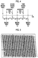
- Fig. 4 is a diagram illustrating the method of determining the imaging timing.
- the control unit 12 of the present embodiment determines the timing of an integral multiple of an interval PP of the timing, at which the same phase is obtained, as an imaging timing. At this time, a point in time that is an integral multiple of the interval PP immediately after the movement of the imaging range may be set as the imaging timing. In the present embodiment, the control unit 12 determines the imaging timing with a slight marginal time.
- the control unit 12 determines a point in time when only a time corresponding to the interval PP has passed from a point in time, at which the imaging unit main body 13 is installed in a first imaging range, as the imaging timing TI1 of the first imaging range. Then, a movement time TM for movement from the first imaging range to the second imaging range is added to the imaging timing TI1, and a point in time t2 at which the imaging unit main body 13 is installed in the second imaging range is calculated.
- the movement time TM of the imaging range is assumed to be set in advance.
- the movement time TM of the imaging range may be calculated from the distance between adjacent imaging ranges and the moving speed of the imaging unit main body 13.
- the point in time t2 is compared with the timing that is an integral multiple of the interval PP, and the timing of an integral multiple of the interval PP after the point in time t2 is determined as an imaging timing.
- a subsequent timing of an integral multiple of the interval PP is determined as the imaging timing.
- a timing of an integral multiple after the timing of an integral multiple of the interval PP immediately after the point in time t2 is determined as the imaging timing TI2.
- a point in time obtained by addition of an integral multiple of the interval PP may be set as the imaging timing TI2.
- a point in time obtained by addition of 2 to 5 times the interval PP may be set as the imaging timing TI2.
- the imaging timing TI3 of the next third imaging range is determined similarly to the imaging timing TI2 of the second imaging range.
- the captured image of each imaging range that has been captured at the imaging timing described above is output to the cell image display control unit 20 so as to be input to the composite image generation unit 22 shown in Fig. 1 .
- the composite image generation unit 22 generates a composite image by tiling the input captured image of each imaging range.
- Tiling means arranging the captured images of respective imaging ranges so as to be arranged at positions corresponding to the imaging ranges without gaps.
- the captured images with the same phase are captured and tilted as described above, it is possible to generate a composite image in which the phase of the periodic movement of the myocardial cell group and the like is the same.
- Fig. 5 shows an example of a composite image.
- Each rectangular range in Fig. 5 corresponds to each imaging range.
- the composite image generated by the composite image generation unit 22 is output to the display control unit 23 shown in Fig. 1 .
- the display control unit 23 displays the input composite image on the display device 3.
- the display device 3 is formed by a display device, such as a liquid crystal display.
- the input device 2 is formed by an input device, such as a keyboard or a mouse.
- the display device 3 may be a touch panel, so that the setting input is received by pressing the touch panel screen by the user.
- the user sets and inputs information based on the timing of the same phase described above using the input device 2 (S10). Specifically, the interval PP of the timing of the same phase is set and input.
- the interval PP of the timing of the same phase is acquired by the phase information acquisition unit 21, and the phase information acquisition unit 21 outputs the interval PP to the control unit 12 of the imaging unit 10. Based on the input interval PP, the control unit 12 determines the imaging timing of the captured image of each imaging range (S12).
- the imaging unit main body 13 moves to the position of a predetermined imaging range (S14). At the imaging timing of the imaging range (S16, YES), the imaging unit main body 13 captures the imaging range (S18).
- the imaging unit main body 13 is transported in the X and Y directions by the X direction transport unit 14 and the Y direction transport unit 15, so that the imaging range is sequentially changed. Accordingly, for each imaging range, imaging is performed at the determined imaging timing (S20, NO). The captured image that has been captured in each imaging range is sequentially output to the composite image generation unit 22 from the imaging unit 10.
- the composite image generation unit 22 when the imaging of all imaging ranges ends (S20, YES), the composite image generation unit 22 generates a composite image by tiling the captured image of each imaging range (S22). The composite image generated by the composite image generation unit 22 is output to the display control unit 23, and the display control unit 23 displays the input composite image on the display device 3 (S24).
- the user sets and inputs the information based on the timing of the same phase using the input device 2.
- a pulsation detection unit 4 that detects the information of the pulsation of a myocardial cell group may be further provided as shown in Fig. 7 , and the phase information acquisition unit 21 may acquire the information of the pulsation detected by the pulsation detection unit 4 and acquire the timing of the same phase from the information of the pulsation.
- the information of the pulsation detected by the pulsation detection unit 4 is, for example, an electrocardiogram as shown in Fig. 3 .
- electrodes may be provided for the stage T on which the myocardial cell group S to be imaged is placed (refer to Fig. 2 ), and the electric potential of the myocardial cell group S may be measured by the electrodes.
- information based on the timing of the same phase is acquired based on the setting input from the user or the input from the pulsation detection unit 4.
- imaging may be performed a plurality of times for each imaging range before capturing images with the same phase as described above, and the timing of the same phase may be acquired based on the captured images acquired by the plurality of imaging operations.
- a specific example thereof will be described with reference to the flowchart shown in Fig. 8 .
- the schematic configuration of the system is the same as that of the cell imaging display system of the first embodiment shown in Fig. 1 .
- the imaging unit main body 13 moves to the position of a predetermined imaging range (S30). Then, the imaging unit main body 13 performs imaging of a plurality of times for a predetermined period in the imaging range to acquire a plurality of captured images for acquiring the timing of the same phase (S32).
- the plurality of captured images for acquiring the timing of the same phase which have been acquired by the imaging unit main body 13, are acquired by the phase information acquisition unit 21, and the phase information acquisition unit 21 acquires the timing of the same phase based on the plurality of input captured images (S34).
- the phase information acquisition unit 21 sequentially calculates a difference between the average brightness of the reference image and the average brightness of the second and subsequent captured images.
- Fig. 9 is a diagram schematically showing the difference between the average brightness of the reference image and the average brightness of the second and subsequent captured images.
- the difference in average brightness also changes periodically according to the periodic movement of the myocardial cell group S to be imaged.
- the difference in average brightness at the contraction timing is the largest.
- the phase information acquisition unit 21 acquires the contraction timing, at which the difference in average brightness is the largest, as the timing of the same phase.
- the method of determining the contraction timing is not limited to the method of acquiring the difference in average brightness as described above.
- the contraction timing may be determined by performing binary classification of the average brightness of the captured image for each time using a clustering method, such as K-means.
- the contraction timing may also be determined by simply determining the average brightness of the captured image for each time using a threshold value.
- the information of the timing of the same phase acquired by the phase information acquisition unit 21 is output to the control unit 12 of the imaging unit 10, and the control unit 12 determines any of the input timing of the same phase as an imaging timing (S36, YES), and performs imaging at the imaging timing to acquire a captured image (S38).
- the imaging unit main body 13 moves to the next imaging range (S30), and the imaging unit main body 13 performs imaging again a plurality of times for a predetermined period in the next imaging range to acquire a plurality of captured images for acquiring the timing of the same phase (S32). Then, the plurality of captured images for acquiring the timing of the same phase, which have been acquired by the imaging unit main body 13, are acquired by the phase information acquisition unit 21. In the same manner as in the case of the previous imaging range, the phase information acquisition unit 21 determines a contraction timing based on the difference in average brightness between a plurality of input captured images, and acquires the contraction timing as information of the timing of the same phase (S34).
- the information of the timing of the same phase acquired by the phase information acquisition unit 21 is output to the control unit 12 of the imaging unit 10, and the control unit 12 determines any of the input timing of the same phase as an imaging timing (S36, YES), and performs imaging at the next imaging timing to acquire a captured image of the next imaging timing (S38).
- the composite image generation unit 22 generates a composite image by tiling the captured image of each imaging range (S42).
- the composite image generated by the composite image generation unit 22 is output to the display control unit 23, and the display control unit 23 displays the input composite image on the display device 3 (S44).
- the contraction timing of the myocardial cell group S is acquired as the timing of the same phase.
- the contraction timing may not be necessarily used, and a timing shifted from the contraction timing by a phase set in advance may be acquired as the timing of the same phase.
- the user may set and input the timing of the same phase arbitrarily using the input device 2.
- the input device 2 corresponds to an in-phase timing receiving unit.
- the timing of the same phase is acquired based on a plurality of captured images captured for the respective imaging ranges.
- the method of acquiring the timing of the same phase is not limited thereto.
- an edge portion of the myocardial cell group S may be imaged for a predetermined period by a camera 16 for imaging timing acquisition that is separately provided, and the timing of the same phase may be acquired based on the amount of movement of the edge portion.
- the camera 16 images the edge portion of the myocardial cell group S for a predetermined period to acquire a plurality of edge images.
- the plurality of edge images are sequentially input to the phase information acquisition unit 21, and the phase information acquisition unit 21 detects each edge portion from the plurality of input edge images. Then, with the position of the edge portion of the edge image captured first as a reference position, the phase information acquisition unit 21 calculates a distance of the edge portion, which is detected from each image, from the reference position.
- Fig. 11 is a diagram schematically showing the distance of an edge portion, which is detected from each image, from the reference position.
- the distance of the edge portion from the reference position also changes periodically according to the periodic movement of the myocardial cell group S to be imaged.
- the edge portion of the myocardial cell group S moves the largest at the time of contraction. For this reason, the distance at the contraction timing becomes the largest. Accordingly, the phase information acquisition unit 21 acquires the contraction timing, at which the distance from the reference position becomes the largest, as the timing of the same phase.
- the contraction timing may be determined by classifying the distance of the edge portion of each captured image from the reference position according to the K-means method.
- the contraction timing may also be determined by simply determining the distance from the reference position using a threshold value.
- the information of the timing of the same phase acquired by the phase information acquisition unit 21 is output to the control unit 12 of the imaging unit 10, and the control unit 12 determines any of the input timing of the same phase as an imaging timing, and performs imaging at the imaging timing.
- Fig. 12 is a block diagram showing the schematic configuration of the cell imaging display system using the cell imaging apparatus of the present embodiment.
- the phase information acquisition unit 21 acquires information based on the timing of the same phase as described above, and determines the imaging timing based on the information to acquire captured images with the same phase.
- captured images with the same phase are acquired by selecting a captured image of the specific phase among a plurality of captured images that are obtained by performing imaging for a predetermined period for each imaging range.
- a cell imaging apparatus 5 of the cell imaging display system of the second embodiment includes an imaging unit 30 and a cell image display control unit 40.
- the imaging unit 30 in the cell imaging display system of the second embodiment is different from the imaging unit 10 of the first embodiment in terms of a method of controlling the imaging element and a method of moving the imaging unit main body.
- the optical system 31, the X direction transport unit 14, and the Y direction transport unit 15 in the imaging unit 30 are the same as those in the first embodiment.
- a control unit 32 of the present embodiment acquires a plurality of captured images by performing imaging for a predetermined period for each imaging range of the cell group S, and outputs the plurality of captured images to an image selection unit 41 of the cell image display control unit 40.
- the cell image display control unit 40 includes the image selection unit 41, a composite image generation unit 42, and a display control unit 43.
- the image selection unit 41 acquires the plurality of captured images, which have been captured for each imaging range by the imaging unit 30, and selects captured images with the same phase from the acquired captured images.
- the image selection unit 41 calculates a difference between the average brightness of the reference image and the average brightness of second and subsequent captured images. Then, the image selection unit 41 selects, for example, captured images between which the difference in average brightness is the largest, as captured images with the same phase. In this case, captured images that are captured at the contraction timing of the myocardial cell group as described above are selected.
- the phase of each captured image to be selected is not limited to the contraction timing, and the user can arbitrarily set the phase of each captured image to be selected using the input device 2 as described above.
- the input device 2 corresponds to an in-phase information receiving unit.
- the composite image generation unit 42 acquires the captured images with the same phase that have been selected for the respective imaging ranges by the image selection unit 41, and generates a composite image by tiling the captured images with the same phase.
- the display control unit 43 displays the input composite image on the display device 3.
- the input device 2 and the display device 3 are the same as those in the first embodiment described above.
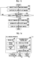
- the imaging unit main body 13 moves to the position of the first imaging range under the control of the control unit 32 (S50), and performs imaging for a predetermined period for each imaging range to acquire a plurality of captured images (S52).
- the imaging unit main body 13 is transported in the X and Y directions by the X direction transport unit 14 and the Y direction transport unit 15, so that the imaging range is sequentially changed. Accordingly, for each imaging range, a plurality of captured images are acquired (S54, NO).
- the image selection unit 41 selects captured images with the same phase among the plurality of captured images that have been captured for each imaging range (S56).
- the captured images with the same phase selected for each imaging range by the image selection unit 41 are output to the composite image generation unit 42, and the composite image generation unit 22 generates a composite image by tiling the captured images with the same phase of each imaging range (S58).
- the composite image generated by the composite image generation unit 22 is output to the display control unit 43, and the display control unit 43 displays the input composite image on the display device 3 (S60).
- captured images with the same phase are selected based on the difference in average brightness between the plurality of captured images.
- the method of selecting captured images with the same phase is not limited thereto.
- an edge portion of a cell group may be imaged by the camera 16 separately provided, and captured images with the same phase may be selected based on the amount of movement of the edge portion.
- the imaging period of a plurality of captured images in each imaging range and the distance of the edge portion from the reference position shown in Fig. 11 may be associated with each other, and captured images that are captured at the contraction timing shown in Fig. 11 may be selected as images with the same phase.
- a pulsation detection unit 4 may be provided as shown in Fig. 14 , and captured images with the same phase may be selected based on the electrocardiogram acquired by the pulsation detection unit 4. Specifically, for example, the imaging period of a plurality of captured images in each imaging range and the electrocardiogram shown in Fig. 3 may be associated with each other, and captured images that are captured at the timing of the peak shown in Fig. 3 , that is, the contraction timing of myocardial cell group, may be selected as images with the same phase.
- the phase of a captured image to be combined can be set arbitrarily as described above.
- the phase of the captured image to be combined is the contraction timing and the relaxation timing of the pulsating movement.
- the phase information acquisition unit 21 acquires both the contraction timing and the relaxation timing
- the imaging unit 10 captures an image at both the contraction timing and the relaxation timing for each imaging range.
- the timing at the start of imaging may be set to the contraction timing and the relaxation timing.
- the composite image generation unit 22 generates a first composite image by arranging the captured image at the contraction timing of each imaging range and generates a second composite image by arranging the image at the relaxation timing of each imaging range and that the display control unit 23 displays the first and second composite images side by side on the display device 3.
- the first and second composite images may be translucently processed, and the translucently processed first and second composite images may be displayed on the display device 3 so as to overlap each other.
- the image selection unit 41 selects both the captured image at the contraction timing and the captured image at the relaxation timing for each imaging range.
- the composite image generation unit 22 generates a first composite image by arranging the captured image at the contraction timing of each imaging range and generates a second composite image by arranging the image at the relaxation timing of each imaging range and that the display control unit 23 displays the first and second composite images on the display device 3.
- a motion picture may be captured by performing imaging at a predetermined frame rate for each imaging range, and a composite image of one frame may be generated by selecting and tilting images of the same phase frame from the motion picture captured for each imaging range.
- a motion picture of a composite image may be generated and displayed by generating a composite image for each phase.
Landscapes
- Engineering & Computer Science (AREA)
- Chemical & Material Sciences (AREA)
- Health & Medical Sciences (AREA)
- Life Sciences & Earth Sciences (AREA)
- Physics & Mathematics (AREA)
- General Physics & Mathematics (AREA)
- General Health & Medical Sciences (AREA)
- Analytical Chemistry (AREA)
- Immunology (AREA)
- Biochemistry (AREA)
- Pathology (AREA)
- Biomedical Technology (AREA)
- Multimedia (AREA)
- Dispersion Chemistry (AREA)
- Molecular Biology (AREA)
- Organic Chemistry (AREA)
- Optics & Photonics (AREA)
- Biophysics (AREA)
- Zoology (AREA)
- Proteomics, Peptides & Aminoacids (AREA)
- Wood Science & Technology (AREA)
- Signal Processing (AREA)
- Theoretical Computer Science (AREA)
- Urology & Nephrology (AREA)
- Hematology (AREA)
- Medicinal Chemistry (AREA)
- Food Science & Technology (AREA)
- Biotechnology (AREA)
- Microbiology (AREA)
- Bioinformatics & Cheminformatics (AREA)
- Computer Vision & Pattern Recognition (AREA)
- General Engineering & Computer Science (AREA)
- Genetics & Genomics (AREA)
- Computer Graphics (AREA)
- Apparatus Associated With Microorganisms And Enzymes (AREA)
- Studio Devices (AREA)
- Measuring Or Testing Involving Enzymes Or Micro-Organisms (AREA)
- Image Analysis (AREA)
- Investigating Or Analysing Materials By Optical Means (AREA)
Abstract
Description
- The present invention relates to a cell imaging apparatus and method for imaging a cell group including a plurality of periodically moving cells.
- In recent years, regenerative medicine for performing treatment by culturing specific cells, such as myocardium, skin, or large intestine, in a sheet form and transplanting these into a patient has been drawing attention.
- When producing a cell sheet, such as myocardium, first, a small amount of cells are collected from the living body, the collected cells are induced to undifferentiated cells, such as iPS cells, and the obtained undifferentiated cells are cultured. Then, the obtained cells are induced to differentiate into myocardial cells, and the differentiated myocardial cells are arranged in a sheet form and are cultured. In this manner, a cell sheet is produced.
- In the process of culturing the cells arranged in a sheet form as described above, visual observation using a microscope and evaluation are performed to check abnormalities. In the future, however, it is conceivable that such evaluation is automatically performed with the spread of regenerative medicine.
- As a method for automatically evaluating the quality, abnormalities, or the like of a cell sheet, for example, a method of capturing an image of a cell sheet using a microscope and acquiring and evaluating the feature quantity of the image can be considered.
- In the case of performing evaluation based on an image obtained by imaging cells, for example, in the case of a small amount of cells, the cells can be contained within the imaging range of one field of view. However, in the case of cells arranged in a sheet form as described above, the cells cannot be contained within the imaging range of one field of view. Accordingly, imaging is performed a plurality of times in multiple fields of view. Then, captured images obtained by performing imaging of a plurality of times as described above are arranged side by side to generate one composite image.
- Here, when generating one composite image from a plurality of captured images as described above, for example, in a case where cells to be imaged are periodically moving cells, such as myocardial cells or large intestine cells, the phase of the periodic movement may differ at the time of imaging each imaging range. For example, myocardial cells differ in shape depending on the phase of pulsation. The upper diagram of
Fig. 15 schematically shows a state when myocardial cells contract, and the lower diagram ofFig. 15 shows a state when myocardial cells are relaxed. - Therefore, in a case where captured images of imaging ranges having different phases are arranged side by side, as shown in
Fig. 16 , it is not possible to match the shapes of cells at the joint, and even an image to be evaluated becomes a poor-quality composite image. -
JP2008-76088A -
WO2011/12220 - In view of the aforementioned problem, it is an object of the present invention to provide a cell imaging apparatus and method capable of generating a high-quality composite image as an image to be evaluated by matching the shapes of cells at the joint when generating one composite image by imaging a group of periodically moving cells in a plurality of imaging ranges and arranging the plurality of captured images side by side.
- A cell imaging apparatus of the present invention comprises: an imaging unit that images a cell group including a plurality of periodically moving cells while changing an imaging range; a phase information acquisition unit that acquires information based on a timing of the same phase in each period of the periodic movement; and a composite image generation unit that generates a composite image by arranging images of the respective imaging ranges. The imaging unit captures images with the same phase for the respective imaging ranges on the basis of the information based on the timing of the same phase, and the composite image generation unit generates the composite image by arranging the images with the same phase.
- In the cell imaging apparatus of the present invention, it is possible to comprise an in-phase timing receiving unit that receives a setting input of a timing of the same phase.
- In a case where the cell group is a myocardial cell group, a pulsation detection unit that detects a pulsation, which is periodic movement of the myocardial cell group, can be provided, and the phase information acquisition unit can acquire the information, which is based on the timing of the same phase, based on information of the pulsation.
- The imaging unit can perform imaging of a plurality of times for each imaging range before capturing the images with the same phase, and the phase information acquisition unit can acquire the information, which is based on the timing of the same phase, based on images acquired by the plurality of imaging operations.
- In a case where the cell group is a myocardial cell group, the phase information acquisition unit can acquire a contraction timing or a relaxation timing in pulsation of the myocardial cell group.
- The phase information acquisition unit can acquire both the contraction timing and the relaxation timing, the imaging unit can capture an image at both the contraction timing and the relaxation timing for each imaging range, and the composite image generation unit can generate a first composite image by arranging images at the contraction timing of each imaging range and generate a second composite image by arranging images at the relaxation timing of each imaging range.
- The imaging unit can determine an imaging timing of the image based on information regarding a predetermined movement time for movement between the imaging ranges adjacent to each other and the information regarding the timing of the same phase.
- A cell imaging apparatus of the present invention comprises: an imaging unit that images a cell group, which includes a plurality of periodically moving cells, a plurality of times for each imaging range while changing an imaging range; an image selection unit that selects images with the same phase in each period of the periodic movement from a plurality of images acquired by a plurality of imaging operations in each imaging range; and a composite image generation unit that generates a composite image by arranging the images with the same phase selected by the image selection unit.
- In the cell imaging apparatus of the present invention described above, it is possible to comprise an in-phase information receiving unit that receives designation of the same phase in each period of the periodic movement.
- In a case where the cell group is a myocardial cell group, it is possible to comprise a pulsation detection unit that detects a pulsation that is periodic movement of the myocardial cell group, and the image selection unit can select the images with the same phase based on information of the pulsation.
- The image selection unit can select the images with the same phase based on images acquired by the plurality of imaging operations.
- In a case where the cell group is a myocardial cell group, the image selection unit can select an image captured at a contraction timing or an image captured at a relaxation timing in pulsation of the myocardial cell group.
- The image selection unit can select both an image captured at the contraction timing and an image captured at the relaxation timing for each imaging range, and the composite image generation unit can generate a first composite image by arranging images at the contraction timing of each imaging range, and can generate a second composite image by arranging images at the relaxation timing of each imaging range.
- A cell imaging method of the present invention is a cell imaging method for imaging a cell group including a plurality of periodically moving cells while changing an imaging range. The cell imaging method includes: acquiring information based on a timing of the same phase in each period of the periodic movement; capturing images with the same phase for the respective imaging ranges on the basis of the information based on the timing of the same phase, and generating a composite image by arranging the images with the same phase of the respective imaging ranges.
- The cell imaging method of the present invention can include: imaging a cell group, which includes a plurality of periodically moving cells, a plurality of times for each imaging range while changing an imaging range; selecting images with the same phase in each period of the periodic movement from a plurality of images acquired by a plurality of imaging operations in each imaging range; and generating a composite image by arranging the selected images with the same phase.
- According to the cell imaging apparatus and method of the present invention, when imaging a cell group including a plurality of periodically moving cells while changing the imaging range, information based on the timing of the same phase in each period of the periodic movement is acquired, images with the same phase are captured for the respective imaging ranges on the basis of the information based on the timing of the same phase, and a composite image is generated by arranging the images with the same phase of the respective imaging ranges. Therefore, since it is possible to match the shapes of cells at the joint of adjacent images, it is possible to generate a high-quality composite image as an image to be evaluated.
- According to the cell imaging apparatus and method of the present invention, a cell group including a plurality of periodically moving cells is imaged a plurality of times for each imaging range while changing the imaging range, images with the same phase in each period of the periodic movement are selected from a plurality of images acquired by a plurality of imaging operations in each imaging range; and a composite image is generated by arranging the selected images with the same phase. Therefore, since it is possible to match the shapes of cells at the joint of adjacent images, it is possible to generate a high-quality composite image as an image to be evaluated.
-
-
Fig. 1 is a block diagram showing the schematic configuration of a cell imaging display system using a first embodiment of a cell imaging apparatus of the present invention. -
Fig. 2 is a perspective view showing the schematic configuration of an imaging unit. -
Fig. 3 is a diagram showing an example of the relationship between an electrocardiogram, which is obtained by electrically detecting the pulsation of a myocardial cell group, and a timing at which the same phase is obtained in each period. -
Fig. 4 is a diagram illustrating a method of determining the imaging timing. -
Fig. 5 is a diagram showing an example of a composite image obtained by tiling a plurality of captured images with the same phase. -
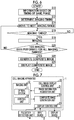
Fig. 6 is a flowchart illustrating the operation of the cell imaging display system using the first embodiment of the cell imaging apparatus of the present invention. -
Fig. 7 is a block diagram showing the schematic configuration of a modification example of the cell imaging display system of the first embodiment. -
Fig. 8 is a flowchart illustrating the operation of the modification example of the cell imaging display system of the first embodiment. -
Fig. 9 is a diagram schematically showing a difference in average brightness between respective captured images. -
Fig. 10 is a diagram showing an example of the configuration of imaging an edge portion of a cell group. -
Fig. 11 is a diagram schematically showing a distance of an edge portion of a cell group from the reference position in each captured image. -
Fig. 12 is a block diagram showing the schematic configuration of a cell imaging display system using a second embodiment of the cell imaging apparatus of the present invention. -
Fig. 13 is a flowchart illustrating the operation of the cell imaging display system using the second embodiment of the cell imaging apparatus of the present invention. -
Fig. 14 is a block diagram showing the schematic configuration of a modification example of the cell imaging display system of the second embodiment. -
Fig. 15 is a diagram schematically showing a state when myocardial cells contract and a state when myocardial cells are relaxed. -
Fig. 16 is a diagram showing an example of a composite image obtained by tiling a plurality of captured images with different phases. - Hereinafter, a cell imaging display system using a first embodiment of a cell imaging apparatus and method of the present invention will be described in detail with reference to the diagrams.
Fig. 1 is a block diagram showing the schematic configuration of the cell imaging display system using the cell imaging apparatus of the present embodiment. - As shown in
Fig. 1 , the cell imaging display system of the present embodiment includes acell imaging apparatus 1, aninput device 2, and a display device 3. - The
cell imaging apparatus 1 includes animaging unit 10 that images a cell group including a plurality of periodically moving cells while sequentially changing the imaging range and a cell imagedisplay control unit 20 that generates a composite image by combining captured images of respective imaging ranges, which are captured by theimaging unit 10, and displays the composite image. As a cell group of periodically moving cells, there is a myocardial cell group including myocardial cells that periodically move by pulsation, a large intestine cell group including large intestine cells, or the like. - The
imaging unit 10 includes anoptical system 11 and acontrol unit 12. Theoptical system 11 includes a microscope for capturing a phase difference image, a bright field image, a differential interference image, or a fluorescence image of a cell group. Theoptical system 11 includes an imaging element, such as a complementary metal-oxide semiconductor (CMOS) sensor or a charge-coupled device (CCD) sensor, and a captured image that is captured by the imaging element is output to the cell imagedisplay control unit 20. As a configuration for capturing the phase difference image, the bright field image, the differential interference image, or the fluorescence image, it is possible to use a known configuration. - The
control unit 12 controls theentire imaging unit 10. Specifically, thecontrol unit 12 of the present embodiment controls the operation, optical magnification, and the like of the imaging element of theoptical system 11. In particular, thecontrol unit 12 of the present embodiment controls the imaging timing of the imaging element, and the imaging timing is controlled based on the timing acquired by a phaseinformation acquisition unit 21 to be described later. A specific method of controlling the imaging timing of an imaging element will be described in detail later. -
Fig. 2 is a perspective view showing the schematic configuration of theimaging unit 10. As shown inFig. 2 , theoptical system 11 and thecontrol unit 12 described above are housed in a casing of an imaging unitmain body 13, and theimaging unit 10 includes an Xdirection transport unit 14 and a Ydirection transport unit 15 to move the imaging unitmain body 13. The Xdirection transport unit 14 transports the imaging unitmain body 13 in an X direction, and the Ydirection transport unit 15 transports the Xdirection transport unit 14 in a Y direction perpendicular to the X direction. Each of the Xdirection transport unit 14 and the Ydirection transport unit 15 is configured to include a transport mechanism, a driving motor for driving the transport mechanism, and the like. As a specific configuration, it is possible to use a known configuration. Thecontrol unit 12 also controls the operations of the Xdirection transport unit 14 and the Ydirection transport unit 15. - As shown in
Fig. 2 , theimaging unit 10 images a cell group S placed on a stage T provided on a side below the Xdirection transport unit 14 and the Ydirection transport unit 15. Theimaging unit 10 captures an image while sequentially changing the imaging range on the cell group S by moving the imaging unitmain body 13 in the X and Y directions using the Xdirection transport unit 14 and the Ydirection transport unit 15 so that the field of view of the imaging unitmain body 13 is sequentially changed. In addition,Fig. 2 schematically shows an imaging range (range indicated by a thick solid line) imaged in one field of view of the imaging unitmain body 13. In addition,Fig. 2 shows an example of a captured image in one imaging range. - Although only the imaging range of three rows by three columns is shown in
Fig. 2 , the number of imaging ranges is determined, in practice, from the size of the cell group S to be imaged and the size of the imaging range of one field of view. The size of the cell group S to be imaged is, for example, several square centimeter to tens of square centimeter in a case where the cell group S is a myocardial sheet including a myocardial cell group. The size of the imaging range of one field of view is, for example, several hundreds of square micrometer in a case where the optical magnification is 10 to 20 times. - In the present embodiment, a microscope is used as the
optical system 11 in theimaging unit 10. However, capturing an image of a group of cells is not limited to the microscope, and an image of each imaging range may be captured by scanning using a line sensor, for example. - Referring back to
Fig. 1 , the cell imagedisplay control unit 20 includes the phaseinformation acquisition unit 21, a compositeimage generation unit 22, and adisplay control unit 23. - The phase
information acquisition unit 21 acquires information based on the timing at which the same phase is obtained in each period of the periodic movement of a myocardial cell group or the like. Here, the timing at which the same phase is obtained in each period will be described using an example of the pulsation of a myocardial cell group.Fig. 3 shows an example of the relationship between an electrocardiogram, which is obtained by electrically detecting the pulsation of a myocardial cell group, and a timing at which the same phase is obtained in each period. - As shown in
Fig. 3 , the electrocardiogram of the myocardial cell group forms a periodic pattern according to the pulsation of the myocardial cell group, but the timing at which the same phase is obtained in each period P of the pattern is, for example, the timing of T1 to T5 shown inFig. 3 . - Then, the phase
information acquisition unit 21 of the present embodiment acquires the interval of the timing at which the same phase is obtained. Specifically, the interval of the timing at which the same phase is obtained is the interval of the timing T1 to T2, timing T2 to T3, timing T3 to T4, or timing T4 to T5 shown inFig. 3 . That is, in the case of the present embodiment, information based on the timing at which the same phase is obtained is the same as the period P of the periodic movement. - In the present embodiment, the interval acquired by the phase
information acquisition unit 21 is set and input by the user using theinput device 2. - Then, the interval acquired by the phase
information acquisition unit 21 is output to thecontrol unit 12 of theimaging unit 10, and thecontrol unit 12 determines the imaging timing of the imaging element based on the input interval and controls the imaging element so that each imaging range of the cell group S is imaged at the imaging timing. When determining the imaging timing of the imaging element, thecontrol unit 12 of the present embodiment also considers a movement time required for the imaging unitmain body 13 to move between adjacent imaging ranges. - Hereinafter, a method of determining the imaging timing in the
control unit 12 will be specifically described.Fig. 4 is a diagram illustrating the method of determining the imaging timing. Thecontrol unit 12 of the present embodiment determines the timing of an integral multiple of an interval PP of the timing, at which the same phase is obtained, as an imaging timing. At this time, a point in time that is an integral multiple of the interval PP immediately after the movement of the imaging range may be set as the imaging timing. In the present embodiment, thecontrol unit 12 determines the imaging timing with a slight marginal time. - Specifically, first, the
control unit 12 determines a point in time when only a time corresponding to the interval PP has passed from a point in time, at which the imaging unitmain body 13 is installed in a first imaging range, as the imaging timing TI1 of the first imaging range. Then, a movement time TM for movement from the first imaging range to the second imaging range is added to the imaging timing TI1, and a point in time t2 at which the imaging unitmain body 13 is installed in the second imaging range is calculated. - The movement time TM of the imaging range is assumed to be set in advance. Alternatively, the movement time TM of the imaging range may be calculated from the distance between adjacent imaging ranges and the moving speed of the imaging unit
main body 13. - Then, the point in time t2 is compared with the timing that is an integral multiple of the interval PP, and the timing of an integral multiple of the interval PP after the point in time t2 is determined as an imaging timing. At this time, in a case where a time between the point in time t2 and the timing, which is an integral multiple of the interval PP immediately after the point in time t2, is short, a subsequent timing of an integral multiple of the interval PP is determined as the imaging timing.
- That is, in the case of the example shown in
Fig. 4 , a timing of an integral multiple after the timing of an integral multiple of the interval PP immediately after the point in time t2 is determined as the imaging timing TI2. Without being limited to the next timing of an integral multiple described above, a point in time obtained by addition of an integral multiple of the interval PP may be set as the imaging timing TI2. For example, a point in time obtained by addition of 2 to 5 times the interval PP may be set as the imaging timing TI2. The imaging timing TI3 of the next third imaging range is determined similarly to the imaging timing TI2 of the second imaging range. By performing imaging at the imaging timing determined in this manner, images with the same phase can be captured for the first to third imaging ranges. - Then, the captured image of each imaging range that has been captured at the imaging timing described above is output to the cell image
display control unit 20 so as to be input to the compositeimage generation unit 22 shown inFig. 1 . - The composite
image generation unit 22 generates a composite image by tiling the input captured image of each imaging range. Tiling means arranging the captured images of respective imaging ranges so as to be arranged at positions corresponding to the imaging ranges without gaps. In the present embodiment, since the captured images with the same phase are captured and tilted as described above, it is possible to generate a composite image in which the phase of the periodic movement of the myocardial cell group and the like is the same. -
Fig. 5 shows an example of a composite image. Each rectangular range inFig. 5 corresponds to each imaging range. By generating a composite image having the same phase in this manner, it is possible to match the shapes of cells at the joint of adjacent captured images. Therefore, it is possible to generate a high-quality composite image as an image to be evaluated. - The composite image generated by the composite
image generation unit 22 is output to thedisplay control unit 23 shown inFig. 1 . Thedisplay control unit 23 displays the input composite image on the display device 3. - The display device 3 is formed by a display device, such as a liquid crystal display. The
input device 2 is formed by an input device, such as a keyboard or a mouse. The display device 3 may be a touch panel, so that the setting input is received by pressing the touch panel screen by the user. - Next, the operation of the cell imaging display system of the present embodiment will be described with reference to the flowchart shown in
Fig. 6 . - First, the user sets and inputs information based on the timing of the same phase described above using the input device 2 (S10). Specifically, the interval PP of the timing of the same phase is set and input.
- The interval PP of the timing of the same phase is acquired by the phase
information acquisition unit 21, and the phaseinformation acquisition unit 21 outputs the interval PP to thecontrol unit 12 of theimaging unit 10. Based on the input interval PP, thecontrol unit 12 determines the imaging timing of the captured image of each imaging range (S12). - Then, the imaging unit
main body 13 moves to the position of a predetermined imaging range (S14). At the imaging timing of the imaging range (S16, YES), the imaging unitmain body 13 captures the imaging range (S18). - Then, the imaging unit
main body 13 is transported in the X and Y directions by the Xdirection transport unit 14 and the Ydirection transport unit 15, so that the imaging range is sequentially changed. Accordingly, for each imaging range, imaging is performed at the determined imaging timing (S20, NO). The captured image that has been captured in each imaging range is sequentially output to the compositeimage generation unit 22 from theimaging unit 10. - Then, when the imaging of all imaging ranges ends (S20, YES), the composite
image generation unit 22 generates a composite image by tiling the captured image of each imaging range (S22). The composite image generated by the compositeimage generation unit 22 is output to thedisplay control unit 23, and thedisplay control unit 23 displays the input composite image on the display device 3 (S24). - In the cell imaging display system of the embodiment described above, the user sets and inputs the information based on the timing of the same phase using the
input device 2. However, without being limited to this, for example, apulsation detection unit 4 that detects the information of the pulsation of a myocardial cell group may be further provided as shown inFig. 7 , and the phaseinformation acquisition unit 21 may acquire the information of the pulsation detected by thepulsation detection unit 4 and acquire the timing of the same phase from the information of the pulsation. The information of the pulsation detected by thepulsation detection unit 4 is, for example, an electrocardiogram as shown inFig. 3 . As the configuration of thepulsation detection unit 4, for example, electrodes may be provided for the stage T on which the myocardial cell group S to be imaged is placed (refer toFig. 2 ), and the electric potential of the myocardial cell group S may be measured by the electrodes. - In the cell imaging display system of the embodiment described above, information based on the timing of the same phase is acquired based on the setting input from the user or the input from the
pulsation detection unit 4. However, without being limited to this, for example, imaging may be performed a plurality of times for each imaging range before capturing images with the same phase as described above, and the timing of the same phase may be acquired based on the captured images acquired by the plurality of imaging operations. Hereinafter, a specific example thereof will be described with reference to the flowchart shown inFig. 8 . Also in this case, the schematic configuration of the system is the same as that of the cell imaging display system of the first embodiment shown inFig. 1 . - First, the imaging unit
main body 13 moves to the position of a predetermined imaging range (S30). Then, the imaging unitmain body 13 performs imaging of a plurality of times for a predetermined period in the imaging range to acquire a plurality of captured images for acquiring the timing of the same phase (S32). - Then, the plurality of captured images for acquiring the timing of the same phase, which have been acquired by the imaging unit
main body 13, are acquired by the phaseinformation acquisition unit 21, and the phaseinformation acquisition unit 21 acquires the timing of the same phase based on the plurality of input captured images (S34). Specifically, with a captured image captured first as a reference image, the phaseinformation acquisition unit 21 sequentially calculates a difference between the average brightness of the reference image and the average brightness of the second and subsequent captured images.Fig. 9 is a diagram schematically showing the difference between the average brightness of the reference image and the average brightness of the second and subsequent captured images. - As shown in
Fig. 9 , the difference in average brightness also changes periodically according to the periodic movement of the myocardial cell group S to be imaged. In particular, in the case of a myocardial cell group, the difference in average brightness at the contraction timing is the largest. Accordingly, the phaseinformation acquisition unit 21 acquires the contraction timing, at which the difference in average brightness is the largest, as the timing of the same phase. The method of determining the contraction timing is not limited to the method of acquiring the difference in average brightness as described above. For example, the contraction timing may be determined by performing binary classification of the average brightness of the captured image for each time using a clustering method, such as K-means. The contraction timing may also be determined by simply determining the average brightness of the captured image for each time using a threshold value. - The information of the timing of the same phase acquired by the phase
information acquisition unit 21 is output to thecontrol unit 12 of theimaging unit 10, and thecontrol unit 12 determines any of the input timing of the same phase as an imaging timing (S36, YES), and performs imaging at the imaging timing to acquire a captured image (S38). - Then, the imaging unit
main body 13 moves to the next imaging range (S30), and the imaging unitmain body 13 performs imaging again a plurality of times for a predetermined period in the next imaging range to acquire a plurality of captured images for acquiring the timing of the same phase (S32). Then, the plurality of captured images for acquiring the timing of the same phase, which have been acquired by the imaging unitmain body 13, are acquired by the phaseinformation acquisition unit 21. In the same manner as in the case of the previous imaging range, the phaseinformation acquisition unit 21 determines a contraction timing based on the difference in average brightness between a plurality of input captured images, and acquires the contraction timing as information of the timing of the same phase (S34). - The information of the timing of the same phase acquired by the phase
information acquisition unit 21 is output to thecontrol unit 12 of theimaging unit 10, and thecontrol unit 12 determines any of the input timing of the same phase as an imaging timing (S36, YES), and performs imaging at the next imaging timing to acquire a captured image of the next imaging timing (S38). - Then, acquisition of the timing of the same phase based on the plurality of captured images and capturing of images based on the timing are repeatedly performed while moving the imaging range as described above, and the captured images with the same phase are sequentially output to the composite
image generation unit 22. Then, when the imaging of all imaging ranges ends (S40, YES), the compositeimage generation unit 22 generates a composite image by tiling the captured image of each imaging range (S42). The composite image generated by the compositeimage generation unit 22 is output to thedisplay control unit 23, and thedisplay control unit 23 displays the input composite image on the display device 3 (S44). - In the above explanation, the contraction timing of the myocardial cell group S is acquired as the timing of the same phase. However, the contraction timing may not be necessarily used, and a timing shifted from the contraction timing by a phase set in advance may be acquired as the timing of the same phase. The user may set and input the timing of the same phase arbitrarily using the
input device 2. In the present embodiment, theinput device 2 corresponds to an in-phase timing receiving unit. - In the above explanation, the timing of the same phase is acquired based on a plurality of captured images captured for the respective imaging ranges. However, the method of acquiring the timing of the same phase is not limited thereto. For example, as shown in
Fig. 10 , an edge portion of the myocardial cell group S may be imaged for a predetermined period by acamera 16 for imaging timing acquisition that is separately provided, and the timing of the same phase may be acquired based on the amount of movement of the edge portion. - Specifically, after the imaging unit
main body 13 is installed at the position of a predetermined imaging range, thecamera 16 images the edge portion of the myocardial cell group S for a predetermined period to acquire a plurality of edge images. The plurality of edge images are sequentially input to the phaseinformation acquisition unit 21, and the phaseinformation acquisition unit 21 detects each edge portion from the plurality of input edge images. Then, with the position of the edge portion of the edge image captured first as a reference position, the phaseinformation acquisition unit 21 calculates a distance of the edge portion, which is detected from each image, from the reference position. -
Fig. 11 is a diagram schematically showing the distance of an edge portion, which is detected from each image, from the reference position. As shown inFig. 11 , the distance of the edge portion from the reference position also changes periodically according to the periodic movement of the myocardial cell group S to be imaged. In the case of the myocardial cell group S, the edge portion of the myocardial cell group S moves the largest at the time of contraction. For this reason, the distance at the contraction timing becomes the largest. Accordingly, the phaseinformation acquisition unit 21 acquires the contraction timing, at which the distance from the reference position becomes the largest, as the timing of the same phase. As a method of determining the contraction timing, for example, the contraction timing may be determined by classifying the distance of the edge portion of each captured image from the reference position according to the K-means method. The contraction timing may also be determined by simply determining the distance from the reference position using a threshold value. - In the same manner as in the above explanation, the information of the timing of the same phase acquired by the phase
information acquisition unit 21 is output to thecontrol unit 12 of theimaging unit 10, and thecontrol unit 12 determines any of the input timing of the same phase as an imaging timing, and performs imaging at the imaging timing. - Next, a cell imaging display system using a second embodiment of the cell imaging apparatus and method of the present invention will be described.
Fig. 12 is a block diagram showing the schematic configuration of the cell imaging display system using the cell imaging apparatus of the present embodiment. - In the cell imaging display system of the first embodiment, the phase
information acquisition unit 21 acquires information based on the timing of the same phase as described above, and determines the imaging timing based on the information to acquire captured images with the same phase. In the cell imaging display system of the present embodiment, however, captured images with the same phase are acquired by selecting a captured image of the specific phase among a plurality of captured images that are obtained by performing imaging for a predetermined period for each imaging range. - A cell imaging apparatus 5 of the cell imaging display system of the second embodiment includes an
imaging unit 30 and a cell imagedisplay control unit 40. - The
imaging unit 30 in the cell imaging display system of the second embodiment is different from theimaging unit 10 of the first embodiment in terms of a method of controlling the imaging element and a method of moving the imaging unit main body. Theoptical system 31, the Xdirection transport unit 14, and the Ydirection transport unit 15 in theimaging unit 30 are the same as those in the first embodiment. - Specifically, a
control unit 32 of the present embodiment acquires a plurality of captured images by performing imaging for a predetermined period for each imaging range of the cell group S, and outputs the plurality of captured images to animage selection unit 41 of the cell imagedisplay control unit 40. - The cell image
display control unit 40 includes theimage selection unit 41, a compositeimage generation unit 42, and adisplay control unit 43. Theimage selection unit 41 acquires the plurality of captured images, which have been captured for each imaging range by theimaging unit 30, and selects captured images with the same phase from the acquired captured images. - As a method of selecting images with the same phase in the
image selection unit 41, it is preferable to use the same method as the above-described method of acquiring the timing of the same phase based on a plurality of captured images. - That is, with a captured image, which is captured first among a plurality of captured images that are captured for a predetermined imaging range, as a reference image, the
image selection unit 41 calculates a difference between the average brightness of the reference image and the average brightness of second and subsequent captured images. Then, theimage selection unit 41 selects, for example, captured images between which the difference in average brightness is the largest, as captured images with the same phase. In this case, captured images that are captured at the contraction timing of the myocardial cell group as described above are selected. However, the phase of each captured image to be selected is not limited to the contraction timing, and the user can arbitrarily set the phase of each captured image to be selected using theinput device 2 as described above. In the present embodiment, theinput device 2 corresponds to an in-phase information receiving unit. - The composite
image generation unit 42 acquires the captured images with the same phase that have been selected for the respective imaging ranges by theimage selection unit 41, and generates a composite image by tiling the captured images with the same phase. Thedisplay control unit 43 displays the input composite image on the display device 3. Theinput device 2 and the display device 3 are the same as those in the first embodiment described above. - Next, the operation of the cell imaging display system of the present embodiment will be described with reference to the flowchart shown in
Fig. 13 . - First, the imaging unit
main body 13 moves to the position of the first imaging range under the control of the control unit 32 (S50), and performs imaging for a predetermined period for each imaging range to acquire a plurality of captured images (S52). - Then, the imaging unit
main body 13 is transported in the X and Y directions by the Xdirection transport unit 14 and the Ydirection transport unit 15, so that the imaging range is sequentially changed. Accordingly, for each imaging range, a plurality of captured images are acquired (S54, NO). - Then, after the capturing of a plurality of images for all imaging ranges ends (S54, YES), the
image selection unit 41 selects captured images with the same phase among the plurality of captured images that have been captured for each imaging range (S56). - The captured images with the same phase selected for each imaging range by the
image selection unit 41 are output to the compositeimage generation unit 42, and the compositeimage generation unit 22 generates a composite image by tiling the captured images with the same phase of each imaging range (S58). The composite image generated by the compositeimage generation unit 22 is output to thedisplay control unit 43, and thedisplay control unit 43 displays the input composite image on the display device 3 (S60). - In the cell imaging display system of the second embodiment described above, captured images with the same phase are selected based on the difference in average brightness between the plurality of captured images. However, the method of selecting captured images with the same phase is not limited thereto. For example, as described in the first embodiment, an edge portion of a cell group may be imaged by the
camera 16 separately provided, and captured images with the same phase may be selected based on the amount of movement of the edge portion. Specifically, the imaging period of a plurality of captured images in each imaging range and the distance of the edge portion from the reference position shown inFig. 11 may be associated with each other, and captured images that are captured at the contraction timing shown inFig. 11 may be selected as images with the same phase. - As in the first embodiment, a
pulsation detection unit 4 may be provided as shown inFig. 14 , and captured images with the same phase may be selected based on the electrocardiogram acquired by thepulsation detection unit 4. Specifically, for example, the imaging period of a plurality of captured images in each imaging range and the electrocardiogram shown inFig. 3 may be associated with each other, and captured images that are captured at the timing of the peak shown inFig. 3 , that is, the contraction timing of myocardial cell group, may be selected as images with the same phase. - In the cell imaging display systems of the first and second embodiments, the phase of a captured image to be combined can be set arbitrarily as described above. However, in a case where the object to be imaged is a myocardial cell group, it is desirable that the phase of the captured image to be combined is the contraction timing and the relaxation timing of the pulsating movement.
- For example, in the case of the cell imaging display system of the first embodiment, the phase
information acquisition unit 21 acquires both the contraction timing and the relaxation timing, and theimaging unit 10 captures an image at both the contraction timing and the relaxation timing for each imaging range. In the cell imaging display system of the first embodiment described above, in a case where the timing of an integral multiple of the interval PP is set as an imaging timing, the timing at the start of imaging may be set to the contraction timing and the relaxation timing. - Then, it is preferable that the composite
image generation unit 22 generates a first composite image by arranging the captured image at the contraction timing of each imaging range and generates a second composite image by arranging the image at the relaxation timing of each imaging range and that thedisplay control unit 23 displays the first and second composite images side by side on the display device 3. - The first and second composite images may be translucently processed, and the translucently processed first and second composite images may be displayed on the display device 3 so as to overlap each other.
- In the case of the cell imaging display system of the second embodiment, the
image selection unit 41 selects both the captured image at the contraction timing and the captured image at the relaxation timing for each imaging range. - Then, it is preferable that the composite
image generation unit 22 generates a first composite image by arranging the captured image at the contraction timing of each imaging range and generates a second composite image by arranging the image at the relaxation timing of each imaging range and that thedisplay control unit 23 displays the first and second composite images on the display device 3. - By comparing the first composite image at the contraction timing with the second composite image at the relaxation timing as described above, it is possible to evaluate the function or quality of the myocardial cell group.
- In the cell imaging display system of the second embodiment described above, a motion picture may be captured by performing imaging at a predetermined frame rate for each imaging range, and a composite image of one frame may be generated by selecting and tilting images of the same phase frame from the motion picture captured for each imaging range. Similarly, a motion picture of a composite image may be generated and displayed by generating a composite image for each phase.
-
- 1, 5:
- cell imaging apparatus
- 2:
- input device
- 3:
- display device
- 4:
- pulsation detection unit
- 10, 30:
- imaging unit
- 11, 31:
- optical system
- 12, 32:
- control unit
- 13:
- imaging unit main body
- 14:
- X direction transport unit
- 15:
- Y direction transport unit
- 16:
- camera
- 20, 40:
- cell image display control unit
- 21:
- phase information acquisition unit
- 22, 42:
- composite image generation unit
- 23, 43:
- display control unit
- 41:
- image selection unit
Claims (15)
- A cell imaging apparatus, comprising:an imaging unit that images a cell group including a plurality of periodically moving cells while changing an imaging range;a phase information acquisition unit that acquires information based on a timing of the same phase in each period of the periodic movement; anda composite image generation unit that generates a composite image by arranging images of the respective imaging ranges,wherein the imaging unit captures images with the same phase for the respective imaging ranges on the basis of the information based on the timing of the same phase, andthe composite image generation unit generates the composite image by arranging the images with the same phase.
- The cell imaging apparatus according to claim 1, further comprising:an in-phase timing receiving unit that receives a setting input of a timing of the same phase.
- The cell imaging apparatus according to claim 1 or 2,wherein the cell group is a myocardial cell group,a pulsation detection unit that detects a pulsation, which is periodic movement of the myocardial cell group, is provided, andthe phase information acquisition unit acquires the information, which is based on the timing of the same phase, based on information of the pulsation.
- The cell imaging apparatus according to claim 1 or 2,wherein the imaging unit performs imaging of a plurality of times for each imaging range before capturing the images with the same phase, andthe phase information acquisition unit acquires the information, which is based on the timing of the same phase, based on images acquired by the plurality of imaging operations.
- The cell imaging apparatus according to any one of claims 1 to 4,wherein the cell group is a myocardial cell group, andthe phase information acquisition unit acquires a contraction timing or a relaxation timing in pulsation of the myocardial cell group.
- The cell imaging apparatus according to claim 5,wherein the phase information acquisition unit acquires both the contraction timing and the relaxation timing,the imaging unit captures an image at both the contraction timing and the relaxation timing for each imaging range, andthe composite image generation unit generates a first composite image by arranging images at the contraction timing of each imaging range, and generates a second composite image by arranging images at the relaxation timing of each imaging range.
- The cell imaging apparatus according to any one of claims 1 to 6,wherein the imaging unit determines an imaging timing of the image based on information regarding a predetermined movement time for movement between the imaging ranges adjacent to each other and the information regarding the timing of the same phase.
- A cell imaging apparatus, comprising:an imaging unit that images a cell group, which includes a plurality of periodically moving cells, a plurality of times for each imaging range while changing an imaging range;an image selection unit that selects images with the same phase in each period of the periodic movement from a plurality of images acquired by a plurality of imaging operations in each imaging range; anda composite image generation unit that generates a composite image by arranging the images with the same phase selected by the image selection unit.
- The cell imaging apparatus according to claim 8, further comprising:an in-phase information receiving unit that receives designation of the same phase in each period of the periodic movement.
- The cell imaging apparatus according to claim 8 or 9,wherein the cell group is a myocardial cell group,a pulsation detection unit that detects a pulsation, which is periodic movement of the myocardial cell group, is provided, andthe image selection unit selects the images with the same phase based on information of the pulsation.
- The cell imaging apparatus according to claim 8 or 9,wherein the image selection unit selects the images with the same phase based on images acquired by the plurality of imaging operations.
- The cell imaging apparatus according to any one of claims 8 to 11,wherein the cell group is a myocardial cell group, andthe image selection unit selects an image captured at a contraction timing or an image captured at a relaxation timing in pulsation of the myocardial cell group.
- The cell imaging apparatus according to claim 12,wherein the image selection unit selects both an image captured at the contraction timing and an image captured at the relaxation timing for each imaging range, andthe composite image generation unit generates a first composite image by arranging images at the contraction timing of each imaging range, and generates a second composite image by arranging images at the relaxation timing of each imaging range.
- A cell imaging method for imaging a cell group including a plurality of periodically moving cells while changing an imaging range, comprising:acquiring information based on a timing of the same phase in each period of the periodic movement;capturing images with the same phase for the respective imaging ranges on the basis of the information based on the timing of the same phase, andgenerating a composite image by arranging the images with the same phase of the respective imaging ranges.
- A cell imaging method, comprising:imaging a cell group, which includes a plurality of periodically moving cells, a plurality of times for each imaging range while changing an imaging range;selecting images with the same phase in each period of the periodic movement from a plurality of images acquired by a plurality of imaging operations in each imaging range; andgenerating a composite image by arranging the selected images with the same phase.
Applications Claiming Priority (2)
| Application Number | Priority Date | Filing Date | Title |
|---|---|---|---|
| JP2014200739A JP6276158B2 (en) | 2014-09-30 | 2014-09-30 | Cell imaging apparatus and method |
| PCT/JP2015/076206 WO2016052179A1 (en) | 2014-09-30 | 2015-09-16 | Cell imaging device and cell imaging method |
Publications (3)
| Publication Number | Publication Date |
|---|---|
| EP3202887A1 true EP3202887A1 (en) | 2017-08-09 |
| EP3202887A4 EP3202887A4 (en) | 2017-12-06 |
| EP3202887B1 EP3202887B1 (en) | 2020-11-04 |
Family
ID=55630221
Family Applications (1)
| Application Number | Title | Priority Date | Filing Date |
|---|---|---|---|
| EP15846168.1A Active EP3202887B1 (en) | 2014-09-30 | 2015-09-16 | Cell imaging device and cell imaging method |
Country Status (4)
| Country | Link |
|---|---|
| US (1) | US10330583B2 (en) |
| EP (1) | EP3202887B1 (en) |
| JP (1) | JP6276158B2 (en) |
| WO (1) | WO2016052179A1 (en) |
Families Citing this family (10)
| Publication number | Priority date | Publication date | Assignee | Title |
|---|---|---|---|---|
| CN105928847B (en) * | 2016-04-19 | 2018-06-26 | 中国科学院过程工程研究所 | A kind of On-line Measuring Method of heterogeneous system middle particle concentration and grain size |
| KR102903119B1 (en) | 2016-07-07 | 2025-12-22 | 코어포토닉스 리미티드 | Linear ball guided voice coil motor for folded optic |
| WO2018122650A1 (en) | 2016-12-28 | 2018-07-05 | Corephotonics Ltd. | Folded camera structure with an extended light-folding-element scanning range |
| US10884321B2 (en) | 2017-01-12 | 2021-01-05 | Corephotonics Ltd. | Compact folded camera |
| CN114137791A (en) | 2017-03-15 | 2022-03-04 | 核心光电有限公司 | Camera device and mobile device with panoramic scanning range |
| JP2019086310A (en) * | 2017-11-02 | 2019-06-06 | 株式会社日立製作所 | Range image camera, range image camera system, and control method thereof |
| US11640047B2 (en) | 2018-02-12 | 2023-05-02 | Corephotonics Ltd. | Folded camera with optical image stabilization |
| KR102795759B1 (en) | 2018-04-23 | 2025-04-11 | 코어포토닉스 리미티드 | An optical-path folding-element with an extended two degree of freedom rotation range |
| JP7181001B2 (en) | 2018-05-24 | 2022-11-30 | 日本電子株式会社 | BIOLOGICAL TISSUE IMAGE PROCESSING SYSTEM AND MACHINE LEARNING METHOD |
| JP7197316B2 (en) * | 2018-09-21 | 2022-12-27 | 株式会社Screenホールディングス | Image processing method, computer program and recording medium |
Family Cites Families (7)
| Publication number | Priority date | Publication date | Assignee | Title |
|---|---|---|---|---|
| CN100569186C (en) * | 2002-03-15 | 2009-12-16 | 比约恩·A·J·安杰尔森 | Ultrasonic imaging method and system, ultrasonic transducer array and probe |
| US7466303B2 (en) * | 2004-02-10 | 2008-12-16 | Sunnybrook Health Sciences Center | Device and process for manipulating real and virtual objects in three-dimensional space |
| JP2007121106A (en) * | 2005-10-27 | 2007-05-17 | Foundation For Biomedical Research & Innovation | Cardiomyocyte monitoring method and monitoring apparatus |
| JP2008076088A (en) * | 2006-09-19 | 2008-04-03 | Foundation For Biomedical Research & Innovation | Cell monitoring method and monitoring apparatus |
| CN102906789B (en) * | 2010-03-29 | 2017-05-17 | 索尼公司 | Data processing device, data processing method, image processing device, image processing method, and program |
| CN104603668B (en) * | 2012-06-07 | 2017-03-15 | 索尼公司 | Image processing apparatus, image processing program and image processing method |
| US10535137B2 (en) | 2014-01-07 | 2020-01-14 | Sony Corporation | Analysis system and analysis method |
-
2014
- 2014-09-30 JP JP2014200739A patent/JP6276158B2/en active Active
-
2015
- 2015-09-16 EP EP15846168.1A patent/EP3202887B1/en active Active
- 2015-09-16 WO PCT/JP2015/076206 patent/WO2016052179A1/en not_active Ceased
-
2017
- 2017-02-21 US US15/437,806 patent/US10330583B2/en active Active
Also Published As
| Publication number | Publication date |
|---|---|
| WO2016052179A1 (en) | 2016-04-07 |
| EP3202887A4 (en) | 2017-12-06 |
| JP2016067287A (en) | 2016-05-09 |
| US10330583B2 (en) | 2019-06-25 |
| US20170167965A1 (en) | 2017-06-15 |
| JP6276158B2 (en) | 2018-02-07 |
| EP3202887B1 (en) | 2020-11-04 |
Similar Documents
| Publication | Publication Date | Title |
|---|---|---|
| EP3202887B1 (en) | Cell imaging device and cell imaging method | |
| CN101048492B (en) | Cell cultivating device, image processing device and cell detecting system | |
| JP6328494B2 (en) | Cell determination apparatus and method, and program | |
| JP5920464B2 (en) | Image processing apparatus, image processing program, and image processing method | |
| EP2262225A1 (en) | Photographing apparatus and microscope system | |
| JP6143365B2 (en) | Cell image evaluation apparatus and method, and program | |
| TWI548742B (en) | Automated cell growth/migration detection system and associated methods | |
| WO2015025506A1 (en) | Stem cell differentiation assessment device, method and program | |
| EP3121264B1 (en) | Cell region display control device and method | |
| JP6563486B2 (en) | Microscope observation system, microscope observation method, and microscope observation program | |
| EP2207137A1 (en) | Motionlessness deciding method and device for photograph object | |
| JP5438315B2 (en) | Cell detection system for cell culture equipment | |
| WO2015116648A1 (en) | Method and system for characterizing cell motion | |
| US11030751B2 (en) | Cell image evaluation device, method, and program | |
| US20190370967A1 (en) | Cell image evaluation device, method, and program | |
| JP6595157B2 (en) | Cell imaging control apparatus and method, and program | |
| EP3521750B1 (en) | Captured image evaluation device, method, and program | |
| JPWO2017098587A1 (en) | Microscope observation system, microscope observation method, and microscope observation program | |
| JP6496814B2 (en) | Cell tracking correction method, cell tracking correction device, and cell tracking correction program | |
| JP2008046305A (en) | Automatic focusing device, microscope, and automatic focusing method | |
| JP6702932B2 (en) | Cell imaging control device, method and program | |
| EP2819397B1 (en) | High dynamic range imaging | |
| EP4177333A1 (en) | Information processing device, information processing method, and program | |
| JP7432319B2 (en) | Floating suspension culture condition monitoring device, floating suspension culture condition monitoring system, computer program, and floating suspension culture condition monitoring method | |
| EP3726273A1 (en) | Observation device, observation method, and observation program |
Legal Events
| Date | Code | Title | Description |
|---|---|---|---|
| STAA | Information on the status of an ep patent application or granted ep patent |
Free format text: STATUS: THE INTERNATIONAL PUBLICATION HAS BEEN MADE |
|
| PUAI | Public reference made under article 153(3) epc to a published international application that has entered the european phase |
Free format text: ORIGINAL CODE: 0009012 |
|
| STAA | Information on the status of an ep patent application or granted ep patent |
Free format text: STATUS: REQUEST FOR EXAMINATION WAS MADE |
|
| 17P | Request for examination filed |
Effective date: 20170221 |
|
| AK | Designated contracting states |
Kind code of ref document: A1 Designated state(s): AL AT BE BG CH CY CZ DE DK EE ES FI FR GB GR HR HU IE IS IT LI LT LU LV MC MK MT NL NO PL PT RO RS SE SI SK SM TR |
|
| AX | Request for extension of the european patent |
Extension state: BA ME |
|
| A4 | Supplementary search report drawn up and despatched |
Effective date: 20171107 |
|
| RIC1 | Information provided on ipc code assigned before grant |
Ipc: G02B 21/36 20060101ALI20171030BHEP Ipc: C12M 3/00 20060101ALI20171030BHEP Ipc: C12Q 1/02 20060101ALI20171030BHEP Ipc: C12M 1/34 20060101AFI20171030BHEP |
|
| DAV | Request for validation of the european patent (deleted) | ||
| DAX | Request for extension of the european patent (deleted) | ||
| STAA | Information on the status of an ep patent application or granted ep patent |
Free format text: STATUS: EXAMINATION IS IN PROGRESS |
|
| 17Q | First examination report despatched |
Effective date: 20190305 |
|
| GRAP | Despatch of communication of intention to grant a patent |
Free format text: ORIGINAL CODE: EPIDOSNIGR1 |
|
| STAA | Information on the status of an ep patent application or granted ep patent |
Free format text: STATUS: GRANT OF PATENT IS INTENDED |
|
| INTG | Intention to grant announced |
Effective date: 20200803 |
|
| GRAS | Grant fee paid |
Free format text: ORIGINAL CODE: EPIDOSNIGR3 |
|
| GRAA | (expected) grant |
Free format text: ORIGINAL CODE: 0009210 |
|
| STAA | Information on the status of an ep patent application or granted ep patent |
Free format text: STATUS: THE PATENT HAS BEEN GRANTED |
|
| AK | Designated contracting states |
Kind code of ref document: B1 Designated state(s): AL AT BE BG CH CY CZ DE DK EE ES FI FR GB GR HR HU IE IS IT LI LT LU LV MC MK MT NL NO PL PT RO RS SE SI SK SM TR |
|
| REG | Reference to a national code |
Ref country code: GB Ref legal event code: FG4D |
|
| REG | Reference to a national code |
Ref country code: CH Ref legal event code: EP |
|
| REG | Reference to a national code |
Ref country code: AT Ref legal event code: REF Ref document number: 1330855 Country of ref document: AT Kind code of ref document: T Effective date: 20201115 |
|
| REG | Reference to a national code |
Ref country code: IE Ref legal event code: FG4D |
|
| REG | Reference to a national code |
Ref country code: DE Ref legal event code: R096 Ref document number: 602015061653 Country of ref document: DE |
|
| REG | Reference to a national code |
Ref country code: NL Ref legal event code: MP Effective date: 20201104 |
|
| RAP4 | Party data changed (patent owner data changed or rights of a patent transferred) |
Owner name: FUJIFILM CORPORATION |
|
| REG | Reference to a national code |
Ref country code: AT Ref legal event code: MK05 Ref document number: 1330855 Country of ref document: AT Kind code of ref document: T Effective date: 20201104 |
|
| PG25 | Lapsed in a contracting state [announced via postgrant information from national office to epo] |
Ref country code: NO Free format text: LAPSE BECAUSE OF FAILURE TO SUBMIT A TRANSLATION OF THE DESCRIPTION OR TO PAY THE FEE WITHIN THE PRESCRIBED TIME-LIMIT Effective date: 20210204 Ref country code: FI Free format text: LAPSE BECAUSE OF FAILURE TO SUBMIT A TRANSLATION OF THE DESCRIPTION OR TO PAY THE FEE WITHIN THE PRESCRIBED TIME-LIMIT Effective date: 20201104 Ref country code: RS Free format text: LAPSE BECAUSE OF FAILURE TO SUBMIT A TRANSLATION OF THE DESCRIPTION OR TO PAY THE FEE WITHIN THE PRESCRIBED TIME-LIMIT Effective date: 20201104 Ref country code: PT Free format text: LAPSE BECAUSE OF FAILURE TO SUBMIT A TRANSLATION OF THE DESCRIPTION OR TO PAY THE FEE WITHIN THE PRESCRIBED TIME-LIMIT Effective date: 20210304 Ref country code: GR Free format text: LAPSE BECAUSE OF FAILURE TO SUBMIT A TRANSLATION OF THE DESCRIPTION OR TO PAY THE FEE WITHIN THE PRESCRIBED TIME-LIMIT Effective date: 20210205 |
|
| PG25 | Lapsed in a contracting state [announced via postgrant information from national office to epo] |
Ref country code: LV Free format text: LAPSE BECAUSE OF FAILURE TO SUBMIT A TRANSLATION OF THE DESCRIPTION OR TO PAY THE FEE WITHIN THE PRESCRIBED TIME-LIMIT Effective date: 20201104 Ref country code: PL Free format text: LAPSE BECAUSE OF FAILURE TO SUBMIT A TRANSLATION OF THE DESCRIPTION OR TO PAY THE FEE WITHIN THE PRESCRIBED TIME-LIMIT Effective date: 20201104 Ref country code: SE Free format text: LAPSE BECAUSE OF FAILURE TO SUBMIT A TRANSLATION OF THE DESCRIPTION OR TO PAY THE FEE WITHIN THE PRESCRIBED TIME-LIMIT Effective date: 20201104 Ref country code: IS Free format text: LAPSE BECAUSE OF FAILURE TO SUBMIT A TRANSLATION OF THE DESCRIPTION OR TO PAY THE FEE WITHIN THE PRESCRIBED TIME-LIMIT Effective date: 20210304 Ref country code: BG Free format text: LAPSE BECAUSE OF FAILURE TO SUBMIT A TRANSLATION OF THE DESCRIPTION OR TO PAY THE FEE WITHIN THE PRESCRIBED TIME-LIMIT Effective date: 20210204 Ref country code: AT Free format text: LAPSE BECAUSE OF FAILURE TO SUBMIT A TRANSLATION OF THE DESCRIPTION OR TO PAY THE FEE WITHIN THE PRESCRIBED TIME-LIMIT Effective date: 20201104 Ref country code: ES Free format text: LAPSE BECAUSE OF FAILURE TO SUBMIT A TRANSLATION OF THE DESCRIPTION OR TO PAY THE FEE WITHIN THE PRESCRIBED TIME-LIMIT Effective date: 20201104 |
|
| REG | Reference to a national code |
Ref country code: LT Ref legal event code: MG9D |
|
| PG25 | Lapsed in a contracting state [announced via postgrant information from national office to epo] |
Ref country code: HR Free format text: LAPSE BECAUSE OF FAILURE TO SUBMIT A TRANSLATION OF THE DESCRIPTION OR TO PAY THE FEE WITHIN THE PRESCRIBED TIME-LIMIT Effective date: 20201104 |
|
| PG25 | Lapsed in a contracting state [announced via postgrant information from national office to epo] |
Ref country code: RO Free format text: LAPSE BECAUSE OF FAILURE TO SUBMIT A TRANSLATION OF THE DESCRIPTION OR TO PAY THE FEE WITHIN THE PRESCRIBED TIME-LIMIT Effective date: 20201104 Ref country code: SK Free format text: LAPSE BECAUSE OF FAILURE TO SUBMIT A TRANSLATION OF THE DESCRIPTION OR TO PAY THE FEE WITHIN THE PRESCRIBED TIME-LIMIT Effective date: 20201104 Ref country code: LT Free format text: LAPSE BECAUSE OF FAILURE TO SUBMIT A TRANSLATION OF THE DESCRIPTION OR TO PAY THE FEE WITHIN THE PRESCRIBED TIME-LIMIT Effective date: 20201104 Ref country code: SM Free format text: LAPSE BECAUSE OF FAILURE TO SUBMIT A TRANSLATION OF THE DESCRIPTION OR TO PAY THE FEE WITHIN THE PRESCRIBED TIME-LIMIT Effective date: 20201104 Ref country code: CZ Free format text: LAPSE BECAUSE OF FAILURE TO SUBMIT A TRANSLATION OF THE DESCRIPTION OR TO PAY THE FEE WITHIN THE PRESCRIBED TIME-LIMIT Effective date: 20201104 Ref country code: EE Free format text: LAPSE BECAUSE OF FAILURE TO SUBMIT A TRANSLATION OF THE DESCRIPTION OR TO PAY THE FEE WITHIN THE PRESCRIBED TIME-LIMIT Effective date: 20201104 |
|
| REG | Reference to a national code |
Ref country code: DE Ref legal event code: R097 Ref document number: 602015061653 Country of ref document: DE |
|
| PG25 | Lapsed in a contracting state [announced via postgrant information from national office to epo] |
Ref country code: DK Free format text: LAPSE BECAUSE OF FAILURE TO SUBMIT A TRANSLATION OF THE DESCRIPTION OR TO PAY THE FEE WITHIN THE PRESCRIBED TIME-LIMIT Effective date: 20201104 |
|
| PLBE | No opposition filed within time limit |
Free format text: ORIGINAL CODE: 0009261 |
|
| STAA | Information on the status of an ep patent application or granted ep patent |
Free format text: STATUS: NO OPPOSITION FILED WITHIN TIME LIMIT |
|
| 26N | No opposition filed |
Effective date: 20210805 |
|
| PG25 | Lapsed in a contracting state [announced via postgrant information from national office to epo] |
Ref country code: NL Free format text: LAPSE BECAUSE OF FAILURE TO SUBMIT A TRANSLATION OF THE DESCRIPTION OR TO PAY THE FEE WITHIN THE PRESCRIBED TIME-LIMIT Effective date: 20201104 Ref country code: AL Free format text: LAPSE BECAUSE OF FAILURE TO SUBMIT A TRANSLATION OF THE DESCRIPTION OR TO PAY THE FEE WITHIN THE PRESCRIBED TIME-LIMIT Effective date: 20201104 Ref country code: IT Free format text: LAPSE BECAUSE OF FAILURE TO SUBMIT A TRANSLATION OF THE DESCRIPTION OR TO PAY THE FEE WITHIN THE PRESCRIBED TIME-LIMIT Effective date: 20201104 |
|
| PG25 | Lapsed in a contracting state [announced via postgrant information from national office to epo] |
Ref country code: SI Free format text: LAPSE BECAUSE OF FAILURE TO SUBMIT A TRANSLATION OF THE DESCRIPTION OR TO PAY THE FEE WITHIN THE PRESCRIBED TIME-LIMIT Effective date: 20201104 |
|
| REG | Reference to a national code |
Ref country code: CH Ref legal event code: PL |
|
| REG | Reference to a national code |
Ref country code: BE Ref legal event code: MM Effective date: 20210930 |
|
| PG25 | Lapsed in a contracting state [announced via postgrant information from national office to epo] |
Ref country code: IS Free format text: LAPSE BECAUSE OF FAILURE TO SUBMIT A TRANSLATION OF THE DESCRIPTION OR TO PAY THE FEE WITHIN THE PRESCRIBED TIME-LIMIT Effective date: 20210304 Ref country code: MC Free format text: LAPSE BECAUSE OF FAILURE TO SUBMIT A TRANSLATION OF THE DESCRIPTION OR TO PAY THE FEE WITHIN THE PRESCRIBED TIME-LIMIT Effective date: 20201104 |
|
| PG25 | Lapsed in a contracting state [announced via postgrant information from national office to epo] |
Ref country code: LU Free format text: LAPSE BECAUSE OF NON-PAYMENT OF DUE FEES Effective date: 20210916 Ref country code: IE Free format text: LAPSE BECAUSE OF NON-PAYMENT OF DUE FEES Effective date: 20210916 Ref country code: BE Free format text: LAPSE BECAUSE OF NON-PAYMENT OF DUE FEES Effective date: 20210930 |
|
| PG25 | Lapsed in a contracting state [announced via postgrant information from national office to epo] |
Ref country code: LI Free format text: LAPSE BECAUSE OF NON-PAYMENT OF DUE FEES Effective date: 20210930 Ref country code: CH Free format text: LAPSE BECAUSE OF NON-PAYMENT OF DUE FEES Effective date: 20210930 |
|
| PG25 | Lapsed in a contracting state [announced via postgrant information from national office to epo] |
Ref country code: HU Free format text: LAPSE BECAUSE OF FAILURE TO SUBMIT A TRANSLATION OF THE DESCRIPTION OR TO PAY THE FEE WITHIN THE PRESCRIBED TIME-LIMIT; INVALID AB INITIO Effective date: 20150916 |
|
| P01 | Opt-out of the competence of the unified patent court (upc) registered |
Effective date: 20230515 |
|
| PG25 | Lapsed in a contracting state [announced via postgrant information from national office to epo] |
Ref country code: CY Free format text: LAPSE BECAUSE OF FAILURE TO SUBMIT A TRANSLATION OF THE DESCRIPTION OR TO PAY THE FEE WITHIN THE PRESCRIBED TIME-LIMIT Effective date: 20201104 |
|
| PG25 | Lapsed in a contracting state [announced via postgrant information from national office to epo] |
Ref country code: MK Free format text: LAPSE BECAUSE OF FAILURE TO SUBMIT A TRANSLATION OF THE DESCRIPTION OR TO PAY THE FEE WITHIN THE PRESCRIBED TIME-LIMIT Effective date: 20201104 |
|
| PG25 | Lapsed in a contracting state [announced via postgrant information from national office to epo] |
Ref country code: TR Free format text: LAPSE BECAUSE OF FAILURE TO SUBMIT A TRANSLATION OF THE DESCRIPTION OR TO PAY THE FEE WITHIN THE PRESCRIBED TIME-LIMIT Effective date: 20201104 |
|
| PG25 | Lapsed in a contracting state [announced via postgrant information from national office to epo] |
Ref country code: MT Free format text: LAPSE BECAUSE OF FAILURE TO SUBMIT A TRANSLATION OF THE DESCRIPTION OR TO PAY THE FEE WITHIN THE PRESCRIBED TIME-LIMIT Effective date: 20201104 |
|
| PGFP | Annual fee paid to national office [announced via postgrant information from national office to epo] |
Ref country code: DE Payment date: 20250730 Year of fee payment: 11 |
|
| PGFP | Annual fee paid to national office [announced via postgrant information from national office to epo] |
Ref country code: GB Payment date: 20250731 Year of fee payment: 11 |
|
| PGFP | Annual fee paid to national office [announced via postgrant information from national office to epo] |
Ref country code: FR Payment date: 20250808 Year of fee payment: 11 |