EP3202616A1 - Climate control by in-seat humidity sensor module - Google Patents
Climate control by in-seat humidity sensor module Download PDFInfo
- Publication number
- EP3202616A1 EP3202616A1 EP16154134.7A EP16154134A EP3202616A1 EP 3202616 A1 EP3202616 A1 EP 3202616A1 EP 16154134 A EP16154134 A EP 16154134A EP 3202616 A1 EP3202616 A1 EP 3202616A1
- Authority
- EP
- European Patent Office
- Prior art keywords
- sensor module
- sensor
- seat
- automotive seat
- wall
- Prior art date
- Legal status (The legal status is an assumption and is not a legal conclusion. Google has not performed a legal analysis and makes no representation as to the accuracy of the status listed.)
- Granted
Links
Images






Classifications
-
- B—PERFORMING OPERATIONS; TRANSPORTING
- B60—VEHICLES IN GENERAL
- B60N—SEATS SPECIALLY ADAPTED FOR VEHICLES; VEHICLE PASSENGER ACCOMMODATION NOT OTHERWISE PROVIDED FOR
- B60N2/00—Seats specially adapted for vehicles; Arrangement or mounting of seats in vehicles
- B60N2/56—Heating or ventilating devices
- B60N2/5607—Heating or ventilating devices characterised by convection
- B60N2/5621—Heating or ventilating devices characterised by convection by air
- B60N2/565—Heating or ventilating devices characterised by convection by air sucked from the seat surface
-
- A—HUMAN NECESSITIES
- A47—FURNITURE; DOMESTIC ARTICLES OR APPLIANCES; COFFEE MILLS; SPICE MILLS; SUCTION CLEANERS IN GENERAL
- A47C—CHAIRS; SOFAS; BEDS
- A47C7/00—Parts, details, or accessories of chairs or stools
- A47C7/62—Accessories for chairs
- A47C7/72—Adaptations for incorporating lamps, radio sets, bars, telephones, ventilation, heating or cooling arrangements or the like
- A47C7/74—Adaptations for incorporating lamps, radio sets, bars, telephones, ventilation, heating or cooling arrangements or the like for ventilation, heating or cooling
- A47C7/742—Adaptations for incorporating lamps, radio sets, bars, telephones, ventilation, heating or cooling arrangements or the like for ventilation, heating or cooling for ventilating or cooling
- A47C7/744—Adaptations for incorporating lamps, radio sets, bars, telephones, ventilation, heating or cooling arrangements or the like for ventilation, heating or cooling for ventilating or cooling with active means, e.g. by using air blowers or liquid pumps
-
- B—PERFORMING OPERATIONS; TRANSPORTING
- B60—VEHICLES IN GENERAL
- B60H—ARRANGEMENTS OF HEATING, COOLING, VENTILATING OR OTHER AIR-TREATING DEVICES SPECIALLY ADAPTED FOR PASSENGER OR GOODS SPACES OF VEHICLES
- B60H1/00—Heating, cooling or ventilating devices
- B60H1/00642—Control systems or circuits; Control members or indication devices for heating, cooling or ventilating devices
- B60H1/00735—Control systems or circuits characterised by their input, i.e. by the detection, measurement or calculation of particular conditions, e.g. signal treatment, dynamic models
- B60H1/00785—Control systems or circuits characterised by their input, i.e. by the detection, measurement or calculation of particular conditions, e.g. signal treatment, dynamic models by the detection of humidity or frost
-
- B—PERFORMING OPERATIONS; TRANSPORTING
- B60—VEHICLES IN GENERAL
- B60H—ARRANGEMENTS OF HEATING, COOLING, VENTILATING OR OTHER AIR-TREATING DEVICES SPECIALLY ADAPTED FOR PASSENGER OR GOODS SPACES OF VEHICLES
- B60H1/00—Heating, cooling or ventilating devices
- B60H1/00642—Control systems or circuits; Control members or indication devices for heating, cooling or ventilating devices
- B60H1/00735—Control systems or circuits characterised by their input, i.e. by the detection, measurement or calculation of particular conditions, e.g. signal treatment, dynamic models
- B60H1/00792—Arrangement of detectors
-
- B—PERFORMING OPERATIONS; TRANSPORTING
- B60—VEHICLES IN GENERAL
- B60H—ARRANGEMENTS OF HEATING, COOLING, VENTILATING OR OTHER AIR-TREATING DEVICES SPECIALLY ADAPTED FOR PASSENGER OR GOODS SPACES OF VEHICLES
- B60H1/00—Heating, cooling or ventilating devices
- B60H1/00642—Control systems or circuits; Control members or indication devices for heating, cooling or ventilating devices
- B60H1/00735—Control systems or circuits characterised by their input, i.e. by the detection, measurement or calculation of particular conditions, e.g. signal treatment, dynamic models
- B60H1/00807—Control systems or circuits characterised by their input, i.e. by the detection, measurement or calculation of particular conditions, e.g. signal treatment, dynamic models the input being a specific way of measuring or calculating an air or coolant temperature
-
- B—PERFORMING OPERATIONS; TRANSPORTING
- B60—VEHICLES IN GENERAL
- B60N—SEATS SPECIALLY ADAPTED FOR VEHICLES; VEHICLE PASSENGER ACCOMMODATION NOT OTHERWISE PROVIDED FOR
- B60N2/00—Seats specially adapted for vehicles; Arrangement or mounting of seats in vehicles
- B60N2/56—Heating or ventilating devices
- B60N2/5607—Heating or ventilating devices characterised by convection
- B60N2/5621—Heating or ventilating devices characterised by convection by air
- B60N2/5628—Heating or ventilating devices characterised by convection by air coming from the vehicle ventilation system, e.g. air-conditioning system
-
- B—PERFORMING OPERATIONS; TRANSPORTING
- B60—VEHICLES IN GENERAL
- B60N—SEATS SPECIALLY ADAPTED FOR VEHICLES; VEHICLE PASSENGER ACCOMMODATION NOT OTHERWISE PROVIDED FOR
- B60N2/00—Seats specially adapted for vehicles; Arrangement or mounting of seats in vehicles
- B60N2/56—Heating or ventilating devices
- B60N2/5607—Heating or ventilating devices characterised by convection
- B60N2/5621—Heating or ventilating devices characterised by convection by air
- B60N2/5657—Heating or ventilating devices characterised by convection by air blown towards the seat surface
-
- B—PERFORMING OPERATIONS; TRANSPORTING
- B60—VEHICLES IN GENERAL
- B60N—SEATS SPECIALLY ADAPTED FOR VEHICLES; VEHICLE PASSENGER ACCOMMODATION NOT OTHERWISE PROVIDED FOR
- B60N2/00—Seats specially adapted for vehicles; Arrangement or mounting of seats in vehicles
- B60N2/56—Heating or ventilating devices
- B60N2/5678—Heating or ventilating devices characterised by electrical systems
- B60N2/5685—Resistance
-
- B—PERFORMING OPERATIONS; TRANSPORTING
- B60—VEHICLES IN GENERAL
- B60N—SEATS SPECIALLY ADAPTED FOR VEHICLES; VEHICLE PASSENGER ACCOMMODATION NOT OTHERWISE PROVIDED FOR
- B60N2/00—Seats specially adapted for vehicles; Arrangement or mounting of seats in vehicles
- B60N2/56—Heating or ventilating devices
- B60N2/5678—Heating or ventilating devices characterised by electrical systems
- B60N2/5692—Refrigerating means
Definitions
- the invention relates to a sensor module as well as to an automotive seat having such a sensor module.
- a sensor module of the afore-mentioned kind is for instance disclosed in EP 2 910 413 A1 .
- a main challenge for integrating modules for measurement of temperature and/or relative humidity in an automotive seat is the goal that such a sensor module shall not decrease the seating comfort of the passenger occupying the respective seat. Seating comfort is immediately decreased when stiff objects are in contact with the passenger. This poses a significant problem for sensor modules that are configured for measuring temperature and/or relative humidity: The closer the sensor module is located to the surface of a seat the higher the likelihood that it causes seating discomfort for the passenger.
- the problem underlying the present invention is to provide a sensor module as well as an automotive seat comprising such a sensor module, which sensor module and seat allow to overcome the above-stated difficulties.
- the sensor module comprises at least a first sensor that is designed to measure relative humidity and/or temperature, wherein the sensor module is configured to be mounted in an automotive seat, which automotive seat comprises a seat cover region forming an outer surface of the seat, which outer surface faces (e.g. contacts) a passenger sitting on the automotive seat, wherein the sensor module is configured to be mounted such in said automotive seat that it is spaced apart from said seat cover region (as well as from said outer surface), particularly such that it is not sensible by the passenger that is sitting on the seat and/or rests against a backrest of the seat.
- said outer surface is a visible surface of the seat (e.g. of a seat bottom or of backrest of the seat), wherein the person using the seat contacts said outer surface while sitting on the automotive seat.
- the comfort of the passenger can be significantly increased by moving the sensor module further away from the outer seat surface as proposed herein. This also improves reliability of the sensor module due to the fact that the sensor is less subject to forces induced by the passenger.
- the sensor module comprises a circumferential wall that surrounds a channel (particularly for guiding air) of the sensor module, wherein said first sensor is arranged in said channel.
- said circumferential wall comprises a tubular shape, particularly a hollow (e.g. circular) cylindrical shape.
- the first sensor is attached to an inside of said wall, wherein particularly the first sensor is arranged in a recess formed in said inside.
- the first sensor is attached to a holding element that protrudes from said inside of said wall into said channel so that the first sensor is arranged closer or even in the center of said channel.
- the holding element can be integrally formed with the wall.
- the sensor module comprises at least one semi-conductor chip configured to measure said relative humidity and/or temperature, particularly a CMOS chip, which chip is particularly mounted on a carrier, e.g. a flat substrate (such as a printed circuit board abbreviated as PCB), that may extend along an extension plane.
- a carrier e.g. a flat substrate (such as a printed circuit board abbreviated as PCB)
- PCB printed circuit board
- the carrier or substrate or first sensor may be embedded into said inside of the wall.
- the first sensor may be arranged in a form-fitting manner in a recess formed in said inside of the wall, such that said back side faces and/or contacts said wall and such that said front side faces the channel.
- the first sensor may however also be attached to the wall by means of glueing, by means of a molding process, or by another suitable fastening means (the same holds for the second sensor described below)
- the extension plane of the carrier or substrate may extend in the axial direction as well as in the radial direction of said wall, e.g., the extension plane or carrier (e.g. substrate or PCB) extends perpendicular to a peripheral direction of said wall.
- the first sensor may be embedded into said holding element protruding from the inside of said wall and may be particularly arranged in a form-fitting manner in a recess formed in said holding element.
- the at least one chip is preferably mounted (e.g. soldered) to the front side of the carrier or substrate, but may also be mounted (e.g. soldered) to the back side of said carrier or substrate.
- said carrier or substrate may be a printed circuit board according to an embodiment of the present invention.
- the sensor module comprises a second sensor that is designed to measure relative humidity and/or temperature, wherein said second sensor is arranged in said channel, wherein the first sensor is attached to the inside of said wall (which inside faces said channel), and wherein the second sensor is attached to a holding element that protrudes from said inside of said wall into said channel.
- the sensor module comprises at least one fastening element which protrudes from an outside of said wall, wherein said at least one fastening element is configured to engage in a form-fitting manner with a recess in a filling material, particularly a foam or fiber layer, of the automotive seat which filling material may surround said wall of the sensor module.
- the sensor module may comprises a circumferential fixture, particularly in the form of a flange, that protrudes in a radial direction from an end of said circumferential (first) wall of the sensor module and is designed to butt against a surface of a material surrounding an opening to an air duct of the seat into which the wall is to be inserted.
- the fixture acts as a stop that prevents further insertion of the wall into said air duct.
- the sensor module may comprise a second circumferential wall having a circumferential fixture at an end of the second wall, too.
- this second wall is preferably designed to slide back and forth on the first wall.
- the second fixture is designed to butt against a second surface of said material of the seat that surrounds a second opening to said air duct of the seat.
- the second wall is designed to be inserted into said air duct from a side facing away from said first surface described above until the second fixture butts against said second surface. In this way, the second fixture also forms a stop that prevents further insertion of the second wall into the air duct.
- the sensor module is designed to compensate a deformation/compression of said material of the seat in which the air duct is formed when a passenger takes place on the seat.
- the circumferential wall may also be tapered in the insertion direction so that the wall can be inserted into an air duct with the tapered head ahead.
- the fastening means described above that protrude from an outside of the wall may be formed as barbed hooks, so as to anchor the wall in the respective air duct or recess.
- the circumferential wall may comprise a plurality of lateral openings (e.g. in the form of slits).
- the sensor module may also comprise a rigid or a flexible carrier for carrying the temperature/relative humidity sensor (e.g. its chip. particularly CMOS chip) that is configured to be attached to the seat by means of sewing and/or gluing.
- a rigid or a flexible carrier for carrying the temperature/relative humidity sensor (e.g. its chip. particularly CMOS chip) that is configured to be attached to the seat by means of sewing and/or gluing.
- the sensor module comprises a fastening means being configured to fasten the first sensor to a ventilator, which ventilator comprises an opening or defines a region, wherein the ventilator is configured to eject air out of the opening or region or to suck air into the opening or region, which opening extends along an opening plane, wherein said axis of the ventilator runs perpendicular to said opening plane or region, and wherein said fastening means is configured to fasten the first sensor to the ventilator such that the first sensor is arranged on said axis of the ventilator in front of said opening or region.
- the fastening means comprises a plurality of arms designed to extend from the first sensor to the ventilator, which arms are configured to engage, particularly engage behind, the ventilator for fasting the first sensor to the ventilator.
- the fastening means is designed such that the first sensor is spaced apart from the ventilator (i.e. from said opening of the ventilator) when the first sensor is fastened to the ventilator by means of the fastening means.
- the fastening means may be designed such that the extension plane of the carrier or substrate is arranged perpendicular to the axis of the ventilator or parallel to said axis when the first sensor is fastened to the ventilator by means of the fastening means.
- an automotive seat also denoted as climate seat, is disclosed according to claim 9.
- the automotive seat comprises a sensor module according to the invention as well as a seat cover region (see also above) forming an outer surface of the seat that faces a passenger sitting on the automotive seat, wherein the sensor module is mounted such in said automotive seat that it is spaced apart from said seat cover region as well as said outer surface, particularly such that it cannot be sensed by the passenger and is particularly not subject to deformations due to the passenger taking place or sitting on the automotive seat.
- the automotive seat comprises a filling material, particularly in the form of a foam or a fiber layer (or some other suitable material), arranged below said seat cover region, which filling material comprises a recess forming an air duct.
- the automotive seat comprises a spacer material, particularly in the form of an air distribution layer, arranged below the filling material and in flow connection to said air duct.
- the automotive seat comprises a further air duct being in flow connection to said air duct in the filling material, particularly via the spacer material (e.g. said air distribution layer), wherein the automotive seat comprises a ventilator configured to force air through said further air duct towards and/or away from said seat cover region.
- a ventilator configured to force air through said further air duct towards and/or away from said seat cover region.
- said ventilator may be configured as described above.
- the ventilator is configured to transport air from the passenger to the sensor module where said air is measured.
- the sensor module is arranged in said air duct of the filling material.
- the sensor module is formed according to one of the above-described embodiments where the sensor module comprises said circumferential wall.
- the outer side of the wall may contact the inside of the air duct in a form-fitting manner (see also above).
- the sensor module is arranged in said spacer material (e.g. in said air distribution layer).
- the sensor module is arranged in said further air duct.
- the sensor module is formed according to one of the above-described embodiments where the sensor module comprises said fastening means for fastening the first sensor to the ventilator.
- the present invention relates to a sensor module 1 comprising at least a first sensor 10 that is designed to measure relative humidity and/or temperature.
- a sensor may be a sensor of the SHT series available from Sensirion AG, Stäfa, Switzerland.
- the sensor module 1 is configured to be mounted in an automotive seat 2 as exemplary shown in Fig. 1 , which automotive seat 2 comprises a seat cover region 200 (e.g. comprising an air permeable layer, for instance a thin sheet of a perforated leather) forming an outer surface 200a of the seat 2 that faces a passenger P sitting on the automotive seat 2, wherein the sensor module 1 is configured to be mounted such in said automotive seat 2 that it is spaced apart from said seat cover region 200.
- said seat cover region 200 belongs to a seat cushion 2a (also denoted as seat bottom), but may also be part of a backrest 2b of the vehicle seat 2.
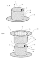
- Figs. 2 to 9b show different embodiments of the sensor module 1 according to the invention.
- the sensor module 1 may comprise a circumferential wall 3, e.g. of a tubular shape, which wall 3 serves for housing a first and a second sensor 10, 20 each being configured to measure relative humidity and/or temperature.
- the first sensor 10 is attached with its carrier (e.g. a PCB or another suitable substrate) 11 carrying an (e.g. CMOS) chip 110 of the first sensor 10 to an inside 3b of the wall 3, particularly by insertion into a recess formed in said inside 3b of the wall 3 or by means of another suitable fastening means.
- the second sensor 20 is attached to a holding element 5 which may be formed integrally with the wall 3 and protrudes from said inside 3b in a radial direction towards a center of the channel 4 formed by the circumferential wall 3.
- a carrier (e.g. a PCB or another suitable substrate) 21 of an (e.g. CMOS) chip 120 of the second sensor 20 may be inserted into a recess formed in the holding element 5 in order to fasten the second sensor 20 to the holding element 5 / wall 3.
- alternative fastening means are conceivable.
- Figs. 3 and 4 show modifications of the embodiment according to Fig. 2 , wherein in Fig. 3 merely a single (first) sensor 10 is present that is fastened to the wall via said holding element 5, while in Fig. 4 merely a single (first) sensor 10 is present that is attached to the inside 3b of the wall as shown in Fig. 2 .
- positioning the first or second sensor 10, 20 closer to the center of the channel 4 using e.g. said holding element 5 has the advantage that the first or second sensor 10, 20 are closer to the main flow of air through channel 4 and comprise a smaller thermal coupling to the wall 3 /seat 2.
- placing the first or second sensor 10, 20 closer to the wall 3 has the advantage of reducing noise since the sensors 10, 20 are then arranged away from the central main flow and cause less turbulence in the channel 4.
- Figure 4b shows a further embodiment of a sensor module 1 according to the present invention, wherein the sensor module 1 comprises a circumferential, particularly tubular, wall 3 that encloses a channel 4 of the sensor module 1, wherein a first sensor 10 for measuring temperature and/or relative humidity is attached to an inside 3b of said wall 3 facing said channel 4.
- the first sensor 10 can be attached to said inside 3b as described above.
- the sensor module 1 comprises a circumferential fixture 30, particularly in the form of a flange, that protrudes in a radial direction from an end of said wall 3 and is designed to butt against a surface of a material (e.g. filling material 203) surrounding an opening to an air duct D or D' of the seat 2 (see also below).
- a material e.g. filling material 203 surrounding an opening to an air duct D or D' of the seat 2 (see also below).
- the fixture 30 acts as a stop that prevents further movement of the wall 3 into said recess/air duct D or D'.
- this embodiment allows for a reproducible positioning of the sensor module 1 with respect to the seat 2.
- Fig. 4c shows a modification of the embodiment shown in Fig. 4b .
- the sensor module 1 comprises, as particularly described with reference to Fig. 4b , also a circumferential, particularly tubular, first wall 3 that encloses a first channel 4, wherein a (first) sensor 10 for measuring temperature and/or relative humidity is attached to an inside 3b of said first wall 3 facing said channel 4.
- the sensor 10 can be attached to said inside 3b as described above.
- the sensor module 1 comprises a circumferential first fixture 30, particularly in the form of a first flange, that protrudes in a radial direction from an end of said first wall 3 and is designed to butt against a first surface of a material (e.g. filling material 203) of the seat 2 surrounding a first opening to an air duct D of the seat 2 (see also below), wherein the first wall 3 is again designed to be inserted into said air duct D until the first fixture 30 butts against said surface.
- a material e.g. filling material 203
- the sensor module 1 now comprises a second circumferential wall 31 in addition, which comprises an outside 31 a and an inside 31 b and encloses a second channel 40, wherein a second circumferential fixture 32, particularly in the form of a second flange, protrudes in a radial direction from an end of said second wall 31.
- the second wall 31 is designed to slide back and forth on the first wall 3 (i.e. the first wall 3 moves/slides inside the second channel 40), wherein guiding means 33 preferably protrude from the outside 3a of the first wall 3 in a radial direction in order to position the second wall 31 with respect to the first wall 3 in a direction perpendicular to said sliding movement.
- guiding means 33 preferably protrude from the outside 3a of the first wall 3 in a radial direction in order to position the second wall 31 with respect to the first wall 3 in a direction perpendicular to said sliding movement.
- the second fixture 32 is designed to butt against a second surface of said material (e.g. filling material 203) of the seat 2 surrounding a second opening to said air duct D of the seat 2 (see also below), which second opening faces the first opening.
- the second wall 31 is designed to be inserted into said air duct D from a side facing away from said first surface until the second fixture 32 butts against said second surface. In this way, the second fixture 32 also forms a stop that prevents further insertion of the second wall 32 into the air duct D.
- the sensor module 1 is designed to compensate a deformation/compression of said material (e.g. filling material 203) in which the air duct D is formed due to a passenger sitting on the seat 2.
- said material e.g. filling material 203
- Figss 4d and 4e show a further embodiment of a sensor module 1 comprising a circumferential (e.g. tubular) wall 3 enclosing a channel 4, wherein again a sensor 10 for measuring temperature and/or humidity is attached to an inside 3b facing said channel 4.
- a circumferential wall 3 enclosing a channel 4
- a sensor 10 for measuring temperature and/or humidity is attached to an inside 3b facing said channel 4.
- the circumferential walls 3 are configured to be inserted into a recess in a material of the seat 2 (i.e. into the filling material 203 and/or into an air duct D) wherein the walls 3 are tapered in the axial direction that corresponds to the insertion direction and are configured to be inserted into the associated recess with the tapered end ahead.
- the sensor modules 1 further comprise fastening means 6 protruding in a radial direction from an outside 3a of the respective wall 3, wherein these fastening means 6 are preferabl ⁇ configured as barbed hooks 6 that anchor the walls 3 in the respective recess/air duct D.
- the sensor module 1 comprises a circumferential wall 3 (e.g. Figs. 2 to 4e )
- the latter does not have to be a solid wall but may also comprise one are several lateral openings 33, particularly elongated axially oriented slits, or may have a mesh form. These openings may be distributed along the periphery of the wall 3.
- Figs. 4g and 4h show cross sectional views of the sensor 10 attached to inside 3b in Figs 2 to 4f .
- the sensor 10 may comprise a flow element 34 being arranged upstream of the chip 110, which flow element 34 comprises a rounded edge facing the air flow and is preferably arranged flush with the chip 110 in a direction normal to said flow or to the carrier 11 of the chip 110.
- flow element 34 can also be absent.
- the sensor module 1 may comprise fastening elements 6 protruding from an outside 3a of wall 3 (which outside 3a faces away from the channel 4), which fastening elements 6 may be integrally formed with the wall 3 and are configured to engage with corresponding recesses of a surrounding material (e.g. a foam) of the seat 2.
- a surrounding material e.g. a foam
- the sensor module 1 which here particularly merely comprises a single (first) sensor 10 configured for measuring relative humidity and/or temperature, comprises a fastening means, wherein said sensor 10 is connected to the ventilator 8 by means of this fastening means 7.
- the ventilator 8 comprises an opening/region 80 for ejecting air or for sucking in air in an axial direction A (also denoted as axis A of the ventilator 8), wherein said axis A runs normal to an opening plane of said opening 80 or normal to said region.
- the fastening means 7 comprises a plurality of arms 70 which extend from the sensor 10 and engage behind the ventilator 8 on a side facing away from the sensor 10.
- the sensor 10 is arranged an said (central) axis A of the ventilator 8 in front of the opening/region 80, wherein the extension plane of the carrier or substrate of the sensor 10 extends parallel to the opening plane (i.e. perpendicular to said axis A).
- Fig. 6 shows a modification of the embodiment shown in Fig. 5 , wherein here the sensor 10 is oriented as in Fig. 5 but is arranged along the axis A at a distance to the ventilator 8 / opening 80 of the ventilator 8. For this, the arms 70 extending from the sensor 10 are inclined with respect to the opening plane of the opening 80 of the ventilator 8.
- Fig. 7 shows a modification of the sensor module 1 of Fig. 6 , wherein now, the extension plane of the carrier or substrate 11 of the sensor 10 extends along the axis A, i.e. perpendicular to the opening plane of opening 80.
- Figs. 5 to 7 are particularly advantageous because they allow a precise and reproducible positioning of the sensor 10 with respect to the ventilator 8 due to the fastening means 7 / arms 70.
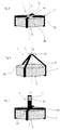
- Figs. 8a to 8c show further embodiments of the sensor module 1 according to the invention wherein here the sensor module 1 comprises a sensor 10 having a rigid carrier 11 onto which a chip 110 (e.g. CMOS) is integrated that is configured to measure temperature and/or relative humidity.
- CMOS complementary metal-oxide-semiconductor
- the chip 110 is arranged in a recess formed on a surface 11 a of the carrier 11, which surface preferably comprises a convex curvature.
- the carrier 11 is designed to attached to a surface/material of the seat 2 (e.g. the air distribution layer 204) with a backside facing away from said surface 11 a which forms a front side of the sensor 10.
- the carrier 11 may comprise a through hole 11 b (formed e.g. in an end section of the carrier 11), which is configured for sewing the carrier 11 to a seat material of the seat 2, in order to attach the carrier 11 to the seat 2.
- the carrier 11 may further comprise indentations 11c on an edge of the carrier 11 which may serve for fastening the carrier 11 to the seat 2, too (e.g. by wrapping an elongated flexible means around the carrier 11 such as a suture).
- Fig. 9a shows yet another embodiment of the sensor module 1 according to the invention, wherein the sensor 10 comprising said chip 110 is attached to a carrier 11 which is a flexible carrier, e.g. out of a fabric.
- this flexible fabric 11 is adapted to be sewn to the seat 2 (e.g. to the air distribution layer 204).
- Fig. 9b shows a view of a modification of the embodiment shown in Fig. 9a .
- the sensor module 1 comprises a rigid carrier 11 a for carrying a chip (e.g. CMOS) 110 of the sensor 10, which is configured to measure temperature and/or relative humidity.
- the rigid carrier 11a is attached to a flexible support (e.g. a fabric) such that the chip 110 is not covered by the flexible support 11.
- the rigid carrier 11 d and the chip 110 arranged thereon extend beyond an edge 11e of the fabric.
- the flexible support 11 can be used to fasten the sensor module 1 to a material of the seat 2, particularly by means of sewing and/or glueing.
- the flexible support 11/edge 11e ends at an edge of the chip 110, wherein said edge 11e of the flexible support 11 may extend parallel to said edge of the chip 110.
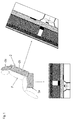
- Figs. 1 and 1b show different (e.g. alternative) positions of a sensor module 1 according to the invention (as e.g. shown in Figs. 2 to 7 ) within an automotive seat 2 according to the invention.
- the automotive seat 2 comprises, according to an embodiment, a seat cushion 2a on which a passenger P can take place, as well as a backrest 2b extending from the seat cushion 2a. Further, the automotive seat 2 may comprise a headrest 2c connected to the backrest 2b. Further, Fig. 1 shows detailed possible cross sections of the seat cushion 2a and backrest 2b which are in described in detail below with reference to Fig. 1 b.
- the seat cushion 2a and/or the backrest 2b may be structured as follows.
- the automotive seat 2 e.g. the seat cushion and/or the backrest 2b
- the automotive seat 2 comprise from top to bottom - wherein the top is configured to be in contact with the passenger taking place on the seat 2 - a seat cover region 200 forming an outer surface 200a of the seat 2 that faces a passenger P and on which the passenger takes place or against which the passenger P rests while sitting on the automotive seat 2.
- the sensor module 1 is mounted such in said automotive seat 2 that it is spaced apart from said seat cover region 200 and thus does not affect or disturb the passenger P, i.e., due to the position of the sensor module 1, the risk that the passenger P may perceive the sensor module 1 is virtually zero.
- the seat cover 200 (also denoted as top layer) may be or comprise an air permeable layer, for instance a (thin) sheet of perforated leather or fabric, or another air permeable flexible planar formation or textile area-measured material.
- an air permeable foam backing 201 can be arranged (or alternatively any other suitable layer) which may have the color of the top layer (e.g. leather/top fabric) such that the material below the top layer 200 is not visible to the passenger P.
- the top layer e.g. leather/top fabric
- an air permeable heating mat 202 for heating the seat 2 can be installed below the top layer 200, particularly below the form backing 201. Further, below said top layer 200, particularly below said heating mat 202 a filling material such as a foam or a fiber layer 203 can be arranged. In this filling material 203 an air duct D is preferably formed as shown in Fig.1b .
- the filling material layer (e.g. foam or fabric) 203 may also be replaced by several separate (e.g. layered) components forming said air duct D. Further, below the filling material 203 an air distribution layer 204 is preferably arranged.
- the air distribution layer 204 is adapted to guide air, particularly between the ducts D, D' (see below) and may also be used as a spacer.
- the air distribution layer 204 can have an opening or flow connection to a further air duct D' in which a ventilator 8 is located.
- the ventilator 8 can blow or most importantly suck air such that air flows from the passenger P through the air duct D, the air distribution layer 204, and the further air duct D' and leaves the seat 2 below the ventilator 8. In this way humidity coming from the passenger P is transported through and out of the seat 2.
- the at least one temperature and/or humidity sensor 10, 20 of the sensor module 1 according to the invention is configured to record temperature and humidity data that are measures of the comfort of the seat's occupant P.
- control unit 13 runs an algorithm to automatically control the amount of air transported through ventilator 8 per time unit, as well as particularly the heating power of the heating mat 202, based on the signals from the sensor module 1. This enables continuous, stepless control of the seat-specific climate. Control can be fully automatic, leading to increased safety since the driver does not need to be concerned with manually adjusting the settings of the heating or ventilator 8. Further, the automatic climate control of the seat 2 can be coupled to a climate system of a vehicle in which the seat 2 may be arranged.
- the sensor module 1 can be arranged in the air duct D of the seat 2 (e.g. an air duct D of the seat cushion 2a or backrest 2b) and may be formed as shown in one of the Figs. 2 to 4j . Further, as indicated in Fig. 1 b , the sensor module 1 may be arranged in the further air duct D' adjacent the ventilator 8 and may be formed as shown in one of the Figs. 5 to 7 . Further, the sensor module 1 may also be arranged in the air distribution layer 204 between the two ducts D and D' and may be formed as shown in one of the Figs. 8a to 9 .
- the seat structure as show in Fig. 1 may vary.
- the air duct D does not necessarily need to be formed in said material/foam 203.
- Other material may also be used.
- the sensor module 1 in tube form can also be fixed to material/foam 203 using glue or glue and the fixture 6 or other fastening means described herein.
- the fastening elements 6 may comprise a different form or can also be absent.
- the module 1 does not necessarily need to have a tube form, it can also be flat and fixed to side wall of an air duct D, 204, or D'.
- the number of the arms 70 according to Figs. 5 to 7 might vary. Furthermore, the module 1 might be directly integrated into the ventilator 8.
- the senor 10 does not have to be placed on the axis A of ventilator 8, but may also be positioned away (offset) from said axis A.
Landscapes
- Engineering & Computer Science (AREA)
- Mechanical Engineering (AREA)
- Aviation & Aerospace Engineering (AREA)
- Transportation (AREA)
- Physics & Mathematics (AREA)
- Thermal Sciences (AREA)
- Air-Conditioning For Vehicles (AREA)
- Seats For Vehicles (AREA)
- Chair Legs, Seat Parts, And Backrests (AREA)
Abstract
Description
- The invention relates to a sensor module as well as to an automotive seat having such a sensor module.
- A sensor module of the afore-mentioned kind is for instance disclosed in
EP 2 910 413 A1 . - A main challenge for integrating modules for measurement of temperature and/or relative humidity in an automotive seat is the goal that such a sensor module shall not decrease the seating comfort of the passenger occupying the respective seat. Seating comfort is immediately decreased when stiff objects are in contact with the passenger. This poses a significant problem for sensor modules that are configured for measuring temperature and/or relative humidity: The closer the sensor module is located to the surface of a seat the higher the likelihood that it causes seating discomfort for the passenger.
- Based on the above, the problem underlying the present invention is to provide a sensor module as well as an automotive seat comprising such a sensor module, which sensor module and seat allow to overcome the above-stated difficulties.
- This problem is solved by a sensor module comprising the features of
claim 1 as well as by an automotive seat having the features of claim 9. Preferred embodiments of these aspects of the present invention are stated in the corresponding sub claims and are described below. - According to
claim 1, the sensor module comprises at least a first sensor that is designed to measure relative humidity and/or temperature, wherein the sensor module is configured to be mounted in an automotive seat, which automotive seat comprises a seat cover region forming an outer surface of the seat, which outer surface faces (e.g. contacts) a passenger sitting on the automotive seat, wherein the sensor module is configured to be mounted such in said automotive seat that it is spaced apart from said seat cover region (as well as from said outer surface), particularly such that it is not sensible by the passenger that is sitting on the seat and/or rests against a backrest of the seat. - Particularly, said outer surface is a visible surface of the seat (e.g. of a seat bottom or of backrest of the seat), wherein the person using the seat contacts said outer surface while sitting on the automotive seat.
- Due to the invention, the comfort of the passenger can be significantly increased by moving the sensor module further away from the outer seat surface as proposed herein. This also improves reliability of the sensor module due to the fact that the sensor is less subject to forces induced by the passenger.
- According to an embodiment of the sensor module according to the invention, the sensor module comprises a circumferential wall that surrounds a channel (particularly for guiding air) of the sensor module, wherein said first sensor is arranged in said channel.
- Particularly, said circumferential wall comprises a tubular shape, particularly a hollow (e.g. circular) cylindrical shape.
- Further, according to an embodiment of the sensor module according to the invention, the first sensor is attached to an inside of said wall, wherein particularly the first sensor is arranged in a recess formed in said inside. Alternatively, the first sensor is attached to a holding element that protrudes from said inside of said wall into said channel so that the first sensor is arranged closer or even in the center of said channel. The holding element can be integrally formed with the wall.
- Further, according to an embodiment of the sensor module according to the invention, the sensor module comprises at least one semi-conductor chip configured to measure said relative humidity and/or temperature, particularly a CMOS chip, which chip is particularly mounted on a carrier, e.g. a flat substrate (such as a printed circuit board abbreviated as PCB), that may extend along an extension plane. Particularly, when the first sensor is attached to said inside of said wall, a front side of said carrier (e.g. flat substrate) faces said channel while the back side of the carrier faces outwards away from the channel, e.g., the extension plane of the carrier essentially extends tangentially or parallel to the inside of the circumferential wall.
- Further, particularly, the carrier or substrate or first sensor may be embedded into said inside of the wall. Particularly, the first sensor may be arranged in a form-fitting manner in a recess formed in said inside of the wall, such that said back side faces and/or contacts said wall and such that said front side faces the channel. The first sensor may however also be attached to the wall by means of glueing, by means of a molding process, or by another suitable fastening means (the same holds for the second sensor described below)
- Further, particularly, when the first sensor is attached to said holding element, the extension plane of the carrier or substrate may extend in the axial direction as well as in the radial direction of said wall, e.g., the extension plane or carrier (e.g. substrate or PCB) extends perpendicular to a peripheral direction of said wall. Also here, the first sensor may be embedded into said holding element protruding from the inside of said wall and may be particularly arranged in a form-fitting manner in a recess formed in said holding element.
- Further, the at least one chip is preferably mounted (e.g. soldered) to the front side of the carrier or substrate, but may also be mounted (e.g. soldered) to the back side of said carrier or substrate. Further, said carrier or substrate may be a printed circuit board according to an embodiment of the present invention.
- Further, according to an embodiment of the sensor module according to the invention, the sensor module comprises a second sensor that is designed to measure relative humidity and/or temperature, wherein said second sensor is arranged in said channel, wherein the first sensor is attached to the inside of said wall (which inside faces said channel), and wherein the second sensor is attached to a holding element that protrudes from said inside of said wall into said channel.
- Further, according to an embodiment of the sensor module according to the invention, the sensor module comprises at least one fastening element which protrudes from an outside of said wall, wherein said at least one fastening element is configured to engage in a form-fitting manner with a recess in a filling material, particularly a foam or fiber layer, of the automotive seat which filling material may surround said wall of the sensor module.
- Furthermore, in an embodiment, the sensor module may comprises a circumferential fixture, particularly in the form of a flange, that protrudes in a radial direction from an end of said circumferential (first) wall of the sensor module and is designed to butt against a surface of a material surrounding an opening to an air duct of the seat into which the wall is to be inserted. Here, the fixture acts as a stop that prevents further insertion of the wall into said air duct. Advantageously, this embodiment allows for a reproducible positioning of the sensor module with respect to the surrounding seat material.
- Furthermore, according to an embodiment, the sensor module may comprise a second circumferential wall having a circumferential fixture at an end of the second wall, too. Here, this second wall is preferably designed to slide back and forth on the first wall. Here, the second fixture is designed to butt against a second surface of said material of the seat that surrounds a second opening to said air duct of the seat. Particularly, the second wall is designed to be inserted into said air duct from a side facing away from said first surface described above until the second fixture butts against said second surface. In this way, the second fixture also forms a stop that prevents further insertion of the second wall into the air duct.
- Due to the fact that the second wall is designed to slide over the first wall, the sensor module is designed to compensate a deformation/compression of said material of the seat in which the air duct is formed when a passenger takes place on the seat.
- Further, according to an embodiment of the present invention, the circumferential wall may also be tapered in the insertion direction so that the wall can be inserted into an air duct with the tapered head ahead. Here, the fastening means described above that protrude from an outside of the wall may be formed as barbed hooks, so as to anchor the wall in the respective air duct or recess.
- Furthermore, in an embodiment of the sensor module according to the invention, the circumferential wall may comprise a plurality of lateral openings (e.g. in the form of slits).
- Furthermore, in certain embodiments, the sensor module may also comprise a rigid or a flexible carrier for carrying the temperature/relative humidity sensor (e.g. its chip. particularly CMOS chip) that is configured to be attached to the seat by means of sewing and/or gluing.
- Further, according to an embodiment of the sensor module according to the invention, the sensor module comprises a fastening means being configured to fasten the first sensor to a ventilator, which ventilator comprises an opening or defines a region, wherein the ventilator is configured to eject air out of the opening or region or to suck air into the opening or region, which opening extends along an opening plane, wherein said axis of the ventilator runs perpendicular to said opening plane or region, and wherein said fastening means is configured to fasten the first sensor to the ventilator such that the first sensor is arranged on said axis of the ventilator in front of said opening or region.
- Further, according to an embodiment of the sensor module according to the invention, the fastening means comprises a plurality of arms designed to extend from the first sensor to the ventilator, which arms are configured to engage, particularly engage behind, the ventilator for fasting the first sensor to the ventilator.
- Further, according to an embodiment of the sensor module according to the invention, the fastening means is designed such that the first sensor is spaced apart from the ventilator (i.e. from said opening of the ventilator) when the first sensor is fastened to the ventilator by means of the fastening means.
- Particularly, according to an embodiment, the fastening means may be designed such that the extension plane of the carrier or substrate is arranged perpendicular to the axis of the ventilator or parallel to said axis when the first sensor is fastened to the ventilator by means of the fastening means.
- According to a further aspect of the present invention, an automotive seat, also denoted as climate seat, is disclosed according to claim 9.
- According thereto, the automotive seat, comprises a sensor module according to the invention as well as a seat cover region (see also above) forming an outer surface of the seat that faces a passenger sitting on the automotive seat, wherein the sensor module is mounted such in said automotive seat that it is spaced apart from said seat cover region as well as said outer surface, particularly such that it cannot be sensed by the passenger and is particularly not subject to deformations due to the passenger taking place or sitting on the automotive seat.
- According to an embodiment of the automotive seat according to the invention, the automotive seat comprises a filling material, particularly in the form of a foam or a fiber layer (or some other suitable material), arranged below said seat cover region, which filling material comprises a recess forming an air duct.
- Further, according to an embodiment of the automotive seat according to the invention, the automotive seat comprises a spacer material, particularly in the form of an air distribution layer, arranged below the filling material and in flow connection to said air duct.
- Further, according to an embodiment of the automotive seat according to the invention, the automotive seat comprises a further air duct being in flow connection to said air duct in the filling material, particularly via the spacer material (e.g. said air distribution layer), wherein the automotive seat comprises a ventilator configured to force air through said further air duct towards and/or away from said seat cover region. Particularly said ventilator may be configured as described above. Particularly, the ventilator is configured to transport air from the passenger to the sensor module where said air is measured.
- Further, according to an embodiment of the automotive seat according to the invention, the sensor module is arranged in said air duct of the filling material. Here, preferably, the sensor module is formed according to one of the above-described embodiments where the sensor module comprises said circumferential wall. Here, the outer side of the wall may contact the inside of the air duct in a form-fitting manner (see also above).
- Further, according to an embodiment of the automotive seat according to the invention, the sensor module is arranged in said spacer material (e.g. in said air distribution layer).
- Further, according to an embodiment of the automotive seat according to the invention, the sensor module is arranged in said further air duct. Here, preferably, the sensor module is formed according to one of the above-described embodiments where the sensor module comprises said fastening means for fastening the first sensor to the ventilator.
- Further embodiments, features and advantages of the present invention will be described below with reference to the Figures, wherein
- Fig. 1
- shows a schematical cross-sectional view of an automotive seat according to the invention, particularly a part of a seat bottom or of a backrest of the seat, wherein the seat comprises a sensor module according to the invention;
- Fig. 2
- shows a perspective view of an embodiment of a sensor module according to the invention comprising a first and a second sensor for measuring relative humidity and/or temperature, respectively;
- Fig. 3
- shows a perspective view of a further embodiment of a sensor module according to the invention, comprising a single (first) sensor for measuring relative humidity and/or temperature;
- Fig. 4
- shows a perspective view of another embodiment of a sensor module according to the invention, comprising a single (first) sensor for measuring relative humidity and/or temperature;
- Fig. 4b
- shows a perspective view of another embodiment of a sensor module having a surrounding wall;
- Fig. 4c
- shows a perspective view of a modification of the embodiment shown in
Fig. 4b ; - Fig. 4d
- shows a perspective view of a further embodiment of a sensor module comprising a surrounding wall and fastening means attached thereto;
- Fig. 4e
- shows a perspective view of a further embodiment of a sensor module comprising a surrounding wall and fastening means attached thereto;
- Fig. 4f
- shows a perspective view of a further embodiment of a sensor module comprising a surrounding wall having a plurality of recesses;
- Fig. 4g and 4h
- show possible details of the first sensor of the sensor module shown in
Figs. 2 to 4f ; - Fig. 4i and 4j
- show possible details of the first sensor of the sensor module shown in
Fig. 3 ; - Fig. 5
- shows a perspective schematical view of a further embodiment of a sensor module according to the invention, comprising a single (first) sensor for measuring relative humidity and/or temperature, which sensor is fastened to a ventilator of the automotive seat by means of a fastening means;
- Fig. 6
- shows a modification of the embodiment shown in
Fig. 5 ; - Fig. 7
- shows a modification of the embodiment shown in
Fig. 6 ; - Figs. 8a - 8c
- show perspective views of three further embodiments of the sensor module according to the invention;
- Fig. 9a
- shows a schematic view of a further embodiment of a sensor module according to the invention; and
- Fig. 9b
- shows a modification of the embodiment shown in
Fig. 9a . - The present invention relates to a
sensor module 1 comprising at least afirst sensor 10 that is designed to measure relative humidity and/or temperature. Such a sensor may be a sensor of the SHT series available from Sensirion AG, Stäfa, Switzerland. - Furthermore, the
sensor module 1 is configured to be mounted in an automotive seat 2 as exemplary shown inFig. 1 , which automotive seat 2 comprises a seat cover region 200 (e.g. comprising an air permeable layer, for instance a thin sheet of a perforated leather) forming anouter surface 200a of the seat 2 that faces a passenger P sitting on the automotive seat 2, wherein thesensor module 1 is configured to be mounted such in said automotive seat 2 that it is spaced apart from saidseat cover region 200. Here, saidseat cover region 200 belongs to aseat cushion 2a (also denoted as seat bottom), but may also be part of abackrest 2b of the vehicle seat 2. -
Figs. 2 to 9b show different embodiments of thesensor module 1 according to the invention. - According to
Fig. 2 , thesensor module 1 may comprise acircumferential wall 3, e.g. of a tubular shape, whichwall 3 serves for housing a first and asecond sensor - As can be seen from
Fig. 3 , thefirst sensor 10 is attached with its carrier (e.g. a PCB or another suitable substrate) 11 carrying an (e.g. CMOS)chip 110 of thefirst sensor 10 to an inside 3b of thewall 3, particularly by insertion into a recess formed in said inside 3b of thewall 3 or by means of another suitable fastening means. In contrast thereto, thesecond sensor 20 is attached to a holdingelement 5 which may be formed integrally with thewall 3 and protrudes from said inside 3b in a radial direction towards a center of thechannel 4 formed by thecircumferential wall 3. Also here, a carrier (e.g. a PCB or another suitable substrate) 21 of an (e.g. CMOS)chip 120 of thesecond sensor 20 may be inserted into a recess formed in the holdingelement 5 in order to fasten thesecond sensor 20 to the holdingelement 5 /wall 3. Also here, alternative fastening means are conceivable. -
Figs. 3 and 4 show modifications of the embodiment according toFig. 2 , wherein inFig. 3 merely a single (first)sensor 10 is present that is fastened to the wall via said holdingelement 5, while inFig. 4 merely a single (first)sensor 10 is present that is attached to the inside 3b of the wall as shown inFig. 2 . - Particularly, regarding
Figs. 2 to 4 , positioning the first orsecond sensor channel 4 using e.g. said holdingelement 5 has the advantage that the first orsecond sensor channel 4 and comprise a smaller thermal coupling to thewall 3 /seat 2. On the other hand, placing the first orsecond sensor wall 3 has the advantage of reducing noise since thesensors channel 4. -
Figure 4b shows a further embodiment of asensor module 1 according to the present invention, wherein thesensor module 1 comprises a circumferential, particularly tubular,wall 3 that encloses achannel 4 of thesensor module 1, wherein afirst sensor 10 for measuring temperature and/or relative humidity is attached to an inside 3b of saidwall 3 facing saidchannel 4. Thefirst sensor 10 can be attached to said inside 3b as described above. - Furthermore, the
sensor module 1 according toFigure 4b comprises acircumferential fixture 30, particularly in the form of a flange, that protrudes in a radial direction from an end of saidwall 3 and is designed to butt against a surface of a material (e.g. filling material 203) surrounding an opening to an air duct D or D' of the seat 2 (see also below). Thus, when thewall 3 is inserted into a recess (e.g. an air duct D or D', see also below), thefixture 30 acts as a stop that prevents further movement of thewall 3 into said recess/air duct D or D'. Thus, advantageously, this embodiment allows for a reproducible positioning of thesensor module 1 with respect to the seat 2. -
Fig. 4c shows a modification of the embodiment shown inFig. 4b . Here thesensor module 1 comprises, as particularly described with reference toFig. 4b , also a circumferential, particularly tubular,first wall 3 that encloses afirst channel 4, wherein a (first)sensor 10 for measuring temperature and/or relative humidity is attached to an inside 3b of saidfirst wall 3 facing saidchannel 4. Thesensor 10 can be attached to said inside 3b as described above. - Furthermore, the
sensor module 1 according toFigure 4c comprises a circumferentialfirst fixture 30, particularly in the form of a first flange, that protrudes in a radial direction from an end of saidfirst wall 3 and is designed to butt against a first surface of a material (e.g. filling material 203) of the seat 2 surrounding a first opening to an air duct D of the seat 2 (see also below), wherein thefirst wall 3 is again designed to be inserted into said air duct D until thefirst fixture 30 butts against said surface. - In contrast to
Fig. 4b , thesensor module 1 now comprises a secondcircumferential wall 31 in addition, which comprises an outside 31 a and an inside 31 b and encloses asecond channel 40, wherein a secondcircumferential fixture 32, particularly in the form of a second flange, protrudes in a radial direction from an end of saidsecond wall 31. - Here, the
second wall 31 is designed to slide back and forth on the first wall 3 (i.e. thefirst wall 3 moves/slides inside the second channel 40), wherein guiding means 33 preferably protrude from the outside 3a of thefirst wall 3 in a radial direction in order to position thesecond wall 31 with respect to thefirst wall 3 in a direction perpendicular to said sliding movement. When thesecond wall 31 is arranged on thefirst wall 3, the inside 31 b of thesecond wall 31 faces the outside 3a of thefirst wall 3. - Similar to the
first fixture 30, thesecond fixture 32 is designed to butt against a second surface of said material (e.g. filling material 203) of the seat 2 surrounding a second opening to said air duct D of the seat 2 (see also below), which second opening faces the first opening. Particularly, thesecond wall 31 is designed to be inserted into said air duct D from a side facing away from said first surface until thesecond fixture 32 butts against said second surface. In this way, thesecond fixture 32 also forms a stop that prevents further insertion of thesecond wall 32 into the air duct D. - Due to the fact that the
second wall 31 is designed to slide over thefirst wall 3, thesensor module 1 is designed to compensate a deformation/compression of said material (e.g. filling material 203) in which the air duct D is formed due to a passenger sitting on the seat 2. - Figss 4d and 4e show a further embodiment of a
sensor module 1 comprising a circumferential (e.g. tubular)wall 3 enclosing achannel 4, wherein again asensor 10 for measuring temperature and/or humidity is attached to an inside 3b facing saidchannel 4. - The
circumferential walls 3 are configured to be inserted into a recess in a material of the seat 2 (i.e. into the fillingmaterial 203 and/or into an air duct D) wherein thewalls 3 are tapered in the axial direction that corresponds to the insertion direction and are configured to be inserted into the associated recess with the tapered end ahead. To prevent thewalls 3 from moving out of the respective recess/air duct D, thesensor modules 1 further comprise fastening means 6 protruding in a radial direction from an outside 3a of therespective wall 3, wherein these fastening means 6 are preferabl< configured asbarbed hooks 6 that anchor thewalls 3 in the respective recess/air duct D. - Further, according to
Fig. 4f , in all embodiments, where thesensor module 1 comprises a circumferential wall 3 (e.g.Figs. 2 to 4e ), the latter does not have to be a solid wall but may also comprise one are severallateral openings 33, particularly elongated axially oriented slits, or may have a mesh form. These openings may be distributed along the periphery of thewall 3. - Furthermore,
Figs. 4g and 4h show cross sectional views of thesensor 10 attached to inside 3b inFigs 2 to 4f . According thereto, thesensor 10 may comprise aflow element 34 being arranged upstream of thechip 110, which flowelement 34 comprises a rounded edge facing the air flow and is preferably arranged flush with thechip 110 in a direction normal to said flow or to thecarrier 11 of thechip 110. However, as shown inFig. 4h , such anelement 34 can also be absent. - Further,
Fig. 4i shows the protruding holdingelement 5 ofFigs. 2 and3 for holding thesensors 10, 20 (comprising thecarriers chips 110, 120) in a plan view. Alternatively, the holdingelement 5 may actually extend across thechannel 4 and may be fixed on both sides to the inside 3b of thewall 3 as shown inFig. 4j . - In all embodiments shown in
Fig. 2 to 4 and 4d to 4f thesensor module 1 may comprisefastening elements 6 protruding from an outside 3a of wall 3 (which outside 3a faces away from the channel 4), whichfastening elements 6 may be integrally formed with thewall 3 and are configured to engage with corresponding recesses of a surrounding material (e.g. a foam) of the seat 2. - Further, according to the embodiments shown in
Fig. 5 to 7 , thesensor module 1, which here particularly merely comprises a single (first)sensor 10 configured for measuring relative humidity and/or temperature, comprises a fastening means, wherein saidsensor 10 is connected to theventilator 8 by means of this fastening means 7. Here, theventilator 8 comprises an opening/region 80 for ejecting air or for sucking in air in an axial direction A (also denoted as axis A of the ventilator 8), wherein said axis A runs normal to an opening plane of saidopening 80 or normal to said region. - According to
Fig. 5 , the fastening means 7 comprises a plurality ofarms 70 which extend from thesensor 10 and engage behind theventilator 8 on a side facing away from thesensor 10. InFig. 5 , thesensor 10 is arranged an said (central) axis A of theventilator 8 in front of the opening/region 80, wherein the extension plane of the carrier or substrate of thesensor 10 extends parallel to the opening plane (i.e. perpendicular to said axis A). -
Fig. 6 shows a modification of the embodiment shown inFig. 5 , wherein here thesensor 10 is oriented as inFig. 5 but is arranged along the axis A at a distance to theventilator 8 /opening 80 of theventilator 8. For this, thearms 70 extending from thesensor 10 are inclined with respect to the opening plane of theopening 80 of theventilator 8. - Finally,
Fig. 7 shows a modification of thesensor module 1 ofFig. 6 , wherein now, the extension plane of the carrier orsubstrate 11 of thesensor 10 extends along the axis A, i.e. perpendicular to the opening plane ofopening 80. - The embodiments according to
Figs. 5 to 7 are particularly advantageous because they allow a precise and reproducible positioning of thesensor 10 with respect to theventilator 8 due to the fastening means 7 /arms 70. -
Figs. 8a to 8c show further embodiments of thesensor module 1 according to the invention wherein here thesensor module 1 comprises asensor 10 having arigid carrier 11 onto which a chip 110 (e.g. CMOS) is integrated that is configured to measure temperature and/or relative humidity. - Particularly, the
chip 110 is arranged in a recess formed on asurface 11 a of thecarrier 11, which surface preferably comprises a convex curvature. - Particularly, the
carrier 11 is designed to attached to a surface/material of the seat 2 (e.g. the air distribution layer 204) with a backside facing away from saidsurface 11 a which forms a front side of thesensor 10. - As shown in
Figs. 8a and 8c , thecarrier 11 may comprise a throughhole 11 b (formed e.g. in an end section of the carrier 11), which is configured for sewing thecarrier 11 to a seat material of the seat 2, in order to attach thecarrier 11 to the seat 2. Thecarrier 11 may further compriseindentations 11c on an edge of thecarrier 11 which may serve for fastening thecarrier 11 to the seat 2, too (e.g. by wrapping an elongated flexible means around thecarrier 11 such as a suture). - In contrast to the embodiments shown in
Figs. 8a to 8c, Fig. 9a shows yet another embodiment of thesensor module 1 according to the invention, wherein thesensor 10 comprising saidchip 110 is attached to acarrier 11 which is a flexible carrier, e.g. out of a fabric. Here, thisflexible fabric 11 is adapted to be sewn to the seat 2 (e.g. to the air distribution layer 204). - Furthermore,
Fig. 9b shows a view of a modification of the embodiment shown inFig. 9a . Here, thesensor module 1 comprises arigid carrier 11 a for carrying a chip (e.g. CMOS) 110 of thesensor 10, which is configured to measure temperature and/or relative humidity. Therigid carrier 11a is attached to a flexible support (e.g. a fabric) such that thechip 110 is not covered by theflexible support 11. Particularly, therigid carrier 11 d and thechip 110 arranged thereon extend beyond anedge 11e of the fabric. Also here, theflexible support 11 can be used to fasten thesensor module 1 to a material of the seat 2, particularly by means of sewing and/or glueing. Further, particularly, theflexible support 11/edge 11e ends at an edge of thechip 110, wherein saidedge 11e of theflexible support 11 may extend parallel to said edge of thechip 110. -
Figs. 1 and1b show different (e.g. alternative) positions of asensor module 1 according to the invention (as e.g. shown inFigs. 2 to 7 ) within an automotive seat 2 according to the invention. - According to
Fig. 1 the automotive seat 2 comprises, according to an embodiment, aseat cushion 2a on which a passenger P can take place, as well as abackrest 2b extending from theseat cushion 2a. Further, the automotive seat 2 may comprise aheadrest 2c connected to thebackrest 2b. Further,Fig. 1 shows detailed possible cross sections of theseat cushion 2a andbackrest 2b which are in described in detail below with reference toFig. 1 b. - According to
Fig. 1 b theseat cushion 2a and/or thebackrest 2b may be structured as follows. The automotive seat 2 (e.g. the seat cushion and/or thebackrest 2b) comprise from top to bottom - wherein the top is configured to be in contact with the passenger taking place on the seat 2 - aseat cover region 200 forming anouter surface 200a of the seat 2 that faces a passenger P and on which the passenger takes place or against which the passenger P rests while sitting on the automotive seat 2. According to the invention, thesensor module 1 is mounted such in said automotive seat 2 that it is spaced apart from saidseat cover region 200 and thus does not affect or disturb the passenger P, i.e., due to the position of thesensor module 1, the risk that the passenger P may perceive thesensor module 1 is virtually zero. - In detail, according to an embodiment of the present invention, the seat cover 200 (also denoted as top layer) may be or comprise an air permeable layer, for instance a (thin) sheet of perforated leather or fabric, or another air permeable flexible planar formation or textile area-measured material.
- Below said
top layer 200 an airpermeable foam backing 201 can be arranged (or alternatively any other suitable layer) which may have the color of the top layer (e.g. leather/top fabric) such that the material below thetop layer 200 is not visible to the passenger P. - Further, an air
permeable heating mat 202 for heating the seat 2 can be installed below thetop layer 200, particularly below theform backing 201. Further, below saidtop layer 200, particularly below said heating mat 202 a filling material such as a foam or afiber layer 203 can be arranged. In this fillingmaterial 203 an air duct D is preferably formed as shown inFig.1b . - The filling material layer (e.g. foam or fabric) 203 may also be replaced by several separate (e.g. layered) components forming said air duct D. Further, below the filling
material 203 anair distribution layer 204 is preferably arranged. Theair distribution layer 204 is adapted to guide air, particularly between the ducts D, D' (see below) and may also be used as a spacer. - Further, the
air distribution layer 204 can have an opening or flow connection to a further air duct D' in which aventilator 8 is located. Theventilator 8 can blow or most importantly suck air such that air flows from the passenger P through the air duct D, theair distribution layer 204, and the further air duct D' and leaves the seat 2 below theventilator 8. In this way humidity coming from the passenger P is transported through and out of the seat 2. - The at least one temperature and/or
humidity sensor sensor module 1 according to the invention is configured to record temperature and humidity data that are measures of the comfort of the seat's occupant P. - Particularly, data from the
sensor module 1 is fed to acontrol unit 13. Thecontrol unit 13 runs an algorithm to automatically control the amount of air transported throughventilator 8 per time unit, as well as particularly the heating power of theheating mat 202, based on the signals from thesensor module 1. This enables continuous, stepless control of the seat-specific climate. Control can be fully automatic, leading to increased safety since the driver does not need to be concerned with manually adjusting the settings of the heating orventilator 8. Further, the automatic climate control of the seat 2 can be coupled to a climate system of a vehicle in which the seat 2 may be arranged. - According to a first embodiment shown in
Fig. 1b , thesensor module 1 can be arranged in the air duct D of the seat 2 (e.g. an air duct D of theseat cushion 2a orbackrest 2b) and may be formed as shown in one of theFigs. 2 to 4j . Further, as indicated inFig. 1 b , thesensor module 1 may be arranged in the further air duct D' adjacent theventilator 8 and may be formed as shown in one of theFigs. 5 to 7 . Further, thesensor module 1 may also be arranged in theair distribution layer 204 between the two ducts D and D' and may be formed as shown in one of theFigs. 8a to 9 . - Of course, other modifications or alternatives are also feasible.
- For instance, the seat structure as show in
Fig. 1 may vary. The air duct D does not necessarily need to be formed in said material/foam 203. Other material may also be used. Further, apart from thefastening elements 6, thesensor module 1 in tube form can also be fixed to material/foam 203 using glue or glue and thefixture 6 or other fastening means described herein. - Further, the
fastening elements 6 may comprise a different form or can also be absent. Further, themodule 1 does not necessarily need to have a tube form, it can also be flat and fixed to side wall of an air duct D, 204, or D'. - Furthermore, the number of the
arms 70 according toFigs. 5 to 7 might vary. Furthermore, themodule 1 might be directly integrated into theventilator 8. - Finally, the
sensor 10 does not have to be placed on the axis A ofventilator 8, but may also be positioned away (offset) from said axis A.
Claims (15)
- Sensor module (1), comprising:- at least a first sensor (10) that is designed to measure relative humidity and/or temperature,characterized in that
the sensor module (1) is configured to be mounted in an automotive seat (2), which automotive seat (2) comprises a seat cover region (200) forming an outer surface (200a) of the seat (2) that faces a passenger (P) sitting on the automotive seat (2), wherein the sensor module (1) is configured to be mounted such in said automotive seat (2) that it is spaced apart from said seat cover region (200). - Sensor module according to claim 1, characterized in that the sensor module (1) comprises a circumferential wall (3) that surrounds a channel (4) of the sensor module (1), wherein said first sensor (10) is arranged in said channel (4).
- Sensor module according to claim 2, characterized in that the first sensor (10) is attached to an inside (3b) of said wall (3) or that the first sensor (10) is attached to a holding element (5) that protrudes from an inside (3b) of said wall (3) into said channel (4).
- Sensor module according to claim 2, characterized in that the sensor module (1) comprises a second sensor (20) that is designed to measure relative humidity and/or temperature, wherein said second sensor (20) is arranged in said channel (4), and wherein the first sensor (10) is attached to an inside (3b) of said wall (3), and wherein the second sensor (20) is attached to a holding element (5) that protrudes from said inside (3b) of said wall (3) into said channel (4).
- Sensor module according to claims 1 to 4, characterized in that the sensor module (1) comprises at least one fastening element (6) which protrudes from an outside (3a) of said wall (3), wherein said at least one fastening element (6) is configured to engage in a form-fitting manner into a recess in a filling material (203) of the automotive seat (2) which material (203) surrounds said wall (3) of the sensor module (1).
- Sensor module according claim 1, characterized in that the sensor module (1) comprises a fastening means (7) being configured to fasten the first sensor (10) to a ventilator (8), which ventilator (8) comprises an opening (80) for ejecting air out of the opening (80) or for sucking air into the opening (80), which opening (80) extends along an opening plane, wherein said axis (A) of the ventilator (8) runs perpendicular to said opening plane, and wherein said fastening means (7) is configured to fasten the first sensor (10) to the ventilator (8) such that the first sensor (10) is arranged on said axis (A) of the ventilator (8) in front of said opening (80).
- Sensor module according to claim 6, characterized in that the fastening means (7) comprises a plurality of arms (70), which arms (70) are configured to engage the ventilator (8) for fasting the first sensor (10) to the ventilator (8).
- Sensor module according to claim 7, characterized in that the fastening means (7) is designed such that the first sensor (10) is spaced apart from the ventilator (8) when the first sensor (10) is fastened to the ventilator (8) by means of the fastening means (7).
- Automotive seat (2), comprising a sensor module (1) according to one of the preceding claims as well as a seat cover region (200) forming an outer surface (200a) of the seat (2) that faces a passenger (P) sitting on the automotive seat (2), wherein the sensor module (1) is mounted such in said automotive seat (2) that it is spaced apart from said seat cover region (200).
- Automotive seat according to claim 9, characterized in that the automotive seat (2) comprises a filling material (203), particularly in the form of a foam or a fiber layer, arranged below said seat cover region (200), which filling material (203) comprises a recess forming an air duct (D).
- Automotive seat according to claim 10, characterized in that the automotive seat (2) comprises an air distribution layer (204) arranged below the filling material (204) and in flow connection to said air duct (D).
- Automotive seat according to claim 10 or 11, characterized in that the automotive seat (2) comprises a further air duct (D') being in flow connection to said air duct (D) of the filling material (203), particularly via the air distribution layer (204), wherein the automotive seat (2) comprises a ventilator (8) configured to force air through said further air duct (D') towards said seat cover region (200) and/or away from said seat cover region (200).
- Automotive seat according to one of the claims 10 to 12, characterized in that the sensor module (1) is arranged in said air duct (D) of the filling material (203).
- Automotive seat according to claim 11, characterized in that the sensor module (1) is arranged in said air distribution layer (204).
- Automotive seat according to claim 12, characterized in that the sensor module (1) is arranged in said further air duct (D').
Priority Applications (5)
| Application Number | Priority Date | Filing Date | Title |
|---|---|---|---|
| EP16154134.7A EP3202616B1 (en) | 2016-02-03 | 2016-02-03 | Climate control by in-seat humidity sensor module |
| KR1020187023613A KR20180102652A (en) | 2016-02-03 | 2017-02-03 | Air conditioning by the humidity sensor module in the seat |
| EP17702407.2A EP3411266B1 (en) | 2016-02-03 | 2017-02-03 | Climate control by in-seat humidity sensor module |
| PCT/EP2017/052441 WO2017134255A1 (en) | 2016-02-03 | 2017-02-03 | Climate control by in-seat humidity sensor module |
| US16/075,142 US10875429B2 (en) | 2016-02-03 | 2017-02-03 | Climate control by in-seat humidity sensor module |
Applications Claiming Priority (1)
| Application Number | Priority Date | Filing Date | Title |
|---|---|---|---|
| EP16154134.7A EP3202616B1 (en) | 2016-02-03 | 2016-02-03 | Climate control by in-seat humidity sensor module |
Publications (2)
| Publication Number | Publication Date |
|---|---|
| EP3202616A1 true EP3202616A1 (en) | 2017-08-09 |
| EP3202616B1 EP3202616B1 (en) | 2020-09-02 |
Family
ID=55310702
Family Applications (2)
| Application Number | Title | Priority Date | Filing Date |
|---|---|---|---|
| EP16154134.7A Active EP3202616B1 (en) | 2016-02-03 | 2016-02-03 | Climate control by in-seat humidity sensor module |
| EP17702407.2A Active EP3411266B1 (en) | 2016-02-03 | 2017-02-03 | Climate control by in-seat humidity sensor module |
Family Applications After (1)
| Application Number | Title | Priority Date | Filing Date |
|---|---|---|---|
| EP17702407.2A Active EP3411266B1 (en) | 2016-02-03 | 2017-02-03 | Climate control by in-seat humidity sensor module |
Country Status (4)
| Country | Link |
|---|---|
| US (1) | US10875429B2 (en) |
| EP (2) | EP3202616B1 (en) |
| KR (1) | KR20180102652A (en) |
| WO (1) | WO2017134255A1 (en) |
Cited By (2)
| Publication number | Priority date | Publication date | Assignee | Title |
|---|---|---|---|---|
| WO2019170622A1 (en) * | 2018-03-06 | 2019-09-12 | Volkswagen Aktiengesellschaft | Integrating sensors into vehicle seats |
| WO2023126032A1 (en) * | 2021-12-31 | 2023-07-06 | Gentherm Gmbh | Ventilation device for a vehicle seat comprising at least one sensor |
Families Citing this family (5)
| Publication number | Priority date | Publication date | Assignee | Title |
|---|---|---|---|---|
| DE102018204103B4 (en) * | 2017-11-06 | 2025-04-17 | Bayerische Motoren Werke Aktiengesellschaft | Method and device for operating an assistance system in a motor vehicle |
| KR102703467B1 (en) * | 2019-10-30 | 2024-09-04 | 현대자동차주식회사 | Humidity responsive system for seat of vehicle |
| EP4102568B1 (en) * | 2020-02-03 | 2025-10-22 | Sony Semiconductor Solutions Corporation | Solid-state imaging element and imaging device |
| JP7552031B2 (en) * | 2020-02-20 | 2024-09-18 | スズキ株式会社 | Vehicle air conditioning system |
| CN116968506A (en) * | 2023-08-30 | 2023-10-31 | 中国第一汽车股份有限公司 | Seat components for vehicles and vehicles |
Citations (7)
| Publication number | Priority date | Publication date | Assignee | Title |
|---|---|---|---|---|
| DE10026656A1 (en) * | 2000-05-29 | 2001-12-13 | Siemens Ag | Climate conditioner for a motor vehicle seat has built in sensors and control unit for seat temperature elements |
| DE10206114C1 (en) * | 2002-02-13 | 2003-05-15 | Wet Automotive Systems Ag | Air conditioning device with controller has electrical resistance devices associated with heater and ventilation device whose resistances can be changed simultaneously by control element |
| US20050200166A1 (en) * | 2004-03-09 | 2005-09-15 | Ki-Yeong Noh | Vehicle seat with cooling/heating device |
| WO2009097572A1 (en) * | 2008-02-01 | 2009-08-06 | Amerigon Incorporated | Condensation and humidity sensors for thermoelectric devices |
| US20130127210A1 (en) * | 2011-11-22 | 2013-05-23 | Kbautotech Co., Ltd. | Ventilation apparatus for seat |
| EP2805869A1 (en) * | 2013-04-26 | 2014-11-26 | I.G. Bauerhin GmbH | Heating device for motor vehicles, seat heater and steering wheel heater with such a heating device and method for controlling the temperature of a heating device for motor vehicles |
| EP2910413A1 (en) | 2014-02-25 | 2015-08-26 | Sensirion AG | Seat assembly with temperature or humidity sensor |
Family Cites Families (12)
| Publication number | Priority date | Publication date | Assignee | Title |
|---|---|---|---|---|
| AU2003221045A1 (en) * | 2002-03-19 | 2003-09-29 | Matsushita Electric Industrial Co., Ltd. | Air conditioning seat device |
| SE526854C2 (en) * | 2003-11-17 | 2005-11-08 | Kongsberg Automotive Ab | Arrangement for ventilation of a vehicle seat |
| US7827805B2 (en) * | 2005-03-23 | 2010-11-09 | Amerigon Incorporated | Seat climate control system |
| JP2007150231A (en) * | 2005-10-27 | 2007-06-14 | Denso Corp | Thermoelectric converter |
| JP2007283932A (en) * | 2006-04-18 | 2007-11-01 | Toyota Motor Corp | Vehicle occupant heating system |
| US20080087316A1 (en) * | 2006-10-12 | 2008-04-17 | Masa Inaba | Thermoelectric device with internal sensor |
| US9989267B2 (en) * | 2012-02-10 | 2018-06-05 | Gentherm Incorporated | Moisture abatement in heating operation of climate controlled systems |
| US10259360B2 (en) * | 2015-09-08 | 2019-04-16 | Ts Tech Co., Ltd. | Seat |
| GB2547881B (en) * | 2016-01-12 | 2019-12-18 | Jaguar Land Rover Ltd | System, method and computer program for thermal control in dependence upon determined heat flux |
| JP2017170983A (en) * | 2016-03-22 | 2017-09-28 | トヨタ紡織株式会社 | Vehicle seat |
| US10814751B2 (en) * | 2017-12-04 | 2020-10-27 | Continental Automotive Gmbh | Method for adjusting a temperature of a seat |
| US10773615B2 (en) * | 2018-05-03 | 2020-09-15 | Ford Global Technologies, Llc | Vehicle seating assembly with ventilated cooling |
-
2016
- 2016-02-03 EP EP16154134.7A patent/EP3202616B1/en active Active
-
2017
- 2017-02-03 WO PCT/EP2017/052441 patent/WO2017134255A1/en not_active Ceased
- 2017-02-03 KR KR1020187023613A patent/KR20180102652A/en active Pending
- 2017-02-03 US US16/075,142 patent/US10875429B2/en not_active Expired - Fee Related
- 2017-02-03 EP EP17702407.2A patent/EP3411266B1/en active Active
Patent Citations (7)
| Publication number | Priority date | Publication date | Assignee | Title |
|---|---|---|---|---|
| DE10026656A1 (en) * | 2000-05-29 | 2001-12-13 | Siemens Ag | Climate conditioner for a motor vehicle seat has built in sensors and control unit for seat temperature elements |
| DE10206114C1 (en) * | 2002-02-13 | 2003-05-15 | Wet Automotive Systems Ag | Air conditioning device with controller has electrical resistance devices associated with heater and ventilation device whose resistances can be changed simultaneously by control element |
| US20050200166A1 (en) * | 2004-03-09 | 2005-09-15 | Ki-Yeong Noh | Vehicle seat with cooling/heating device |
| WO2009097572A1 (en) * | 2008-02-01 | 2009-08-06 | Amerigon Incorporated | Condensation and humidity sensors for thermoelectric devices |
| US20130127210A1 (en) * | 2011-11-22 | 2013-05-23 | Kbautotech Co., Ltd. | Ventilation apparatus for seat |
| EP2805869A1 (en) * | 2013-04-26 | 2014-11-26 | I.G. Bauerhin GmbH | Heating device for motor vehicles, seat heater and steering wheel heater with such a heating device and method for controlling the temperature of a heating device for motor vehicles |
| EP2910413A1 (en) | 2014-02-25 | 2015-08-26 | Sensirion AG | Seat assembly with temperature or humidity sensor |
Cited By (2)
| Publication number | Priority date | Publication date | Assignee | Title |
|---|---|---|---|---|
| WO2019170622A1 (en) * | 2018-03-06 | 2019-09-12 | Volkswagen Aktiengesellschaft | Integrating sensors into vehicle seats |
| WO2023126032A1 (en) * | 2021-12-31 | 2023-07-06 | Gentherm Gmbh | Ventilation device for a vehicle seat comprising at least one sensor |
Also Published As
| Publication number | Publication date |
|---|---|
| US10875429B2 (en) | 2020-12-29 |
| US20180370400A1 (en) | 2018-12-27 |
| WO2017134255A1 (en) | 2017-08-10 |
| EP3411266A1 (en) | 2018-12-12 |
| EP3411266B1 (en) | 2021-08-25 |
| EP3202616B1 (en) | 2020-09-02 |
| KR20180102652A (en) | 2018-09-17 |
Similar Documents
| Publication | Publication Date | Title |
|---|---|---|
| EP3202616B1 (en) | Climate control by in-seat humidity sensor module | |
| JP6177653B2 (en) | Vehicle seat | |
| EP3632268B1 (en) | Ventilation mat | |
| CN100480095C (en) | Vehicle seat | |
| US8220869B2 (en) | Temperature-and-humidity-controlled head restraint | |
| KR20110051692A (en) | Car seat for cooling and heating | |
| JP5635192B2 (en) | Vehicle seat | |
| KR101054489B1 (en) | Ventilated seat with front breathable material | |
| US20070063551A1 (en) | Arrangement for ventilation of a vehicle seat | |
| US20130088064A1 (en) | Seat frame for a vehicle seat | |
| JP2000325186A (en) | Pressure sensor unit for seat | |
| US20090134675A1 (en) | Motor Vehicle Seat Provided With a Ventilation Device | |
| US9139118B2 (en) | Ventilating device | |
| US20100045079A1 (en) | Alignment system for a spacer layer in a ventilated seat | |
| CN1543407A (en) | Motor Vehicle Seat Cushion | |
| WO2014091705A1 (en) | Vehicle-mounted heater device | |
| JP2015504020A (en) | Seat belt guide device in seat with built-in seat belt | |
| US20110221242A1 (en) | Air conditioning device for seats | |
| JP6500704B2 (en) | Sensor member | |
| CN209257940U (en) | Pneumatic massage airbag apparatus suitable for automotive seat | |
| JP2008037326A (en) | Seat belt device | |
| CN101058301A (en) | Device for adjusting air, detecting and seating | |
| JP2016147608A (en) | Sheet | |
| CN111655535A (en) | Foam member for motor vehicle seat with seat occupancy recognition function and method of making the same | |
| KR101372515B1 (en) | Apparatus for ventilating seat of vehicle |
Legal Events
| Date | Code | Title | Description |
|---|---|---|---|
| PUAI | Public reference made under article 153(3) epc to a published international application that has entered the european phase |
Free format text: ORIGINAL CODE: 0009012 |
|
| STAA | Information on the status of an ep patent application or granted ep patent |
Free format text: STATUS: THE APPLICATION HAS BEEN PUBLISHED |
|
| AK | Designated contracting states |
Kind code of ref document: A1 Designated state(s): AL AT BE BG CH CY CZ DE DK EE ES FI FR GB GR HR HU IE IS IT LI LT LU LV MC MK MT NL NO PL PT RO RS SE SI SK SM TR |
|
| AX | Request for extension of the european patent |
Extension state: BA ME |
|
| RIN1 | Information on inventor provided before grant (corrected) |
Inventor name: GRAF, MARKUS Inventor name: GOETZE, MICHAEL Inventor name: HOPPENAU, LUKAS |
|
| STAA | Information on the status of an ep patent application or granted ep patent |
Free format text: STATUS: REQUEST FOR EXAMINATION WAS MADE |
|
| 17P | Request for examination filed |
Effective date: 20171005 |
|
| RAP1 | Party data changed (applicant data changed or rights of an application transferred) |
Owner name: SENSIRION AG |
|
| RBV | Designated contracting states (corrected) |
Designated state(s): AL AT BE BG CH CY CZ DE DK EE ES FI FR GB GR HR HU IE IS IT LI LT LU LV MC MK MT NL NO PL PT RO RS SE SI SK SM TR |
|
| RAP1 | Party data changed (applicant data changed or rights of an application transferred) |
Owner name: SENSIRION AUTOMOTIVE SOLUTIONS AG |
|
| GRAP | Despatch of communication of intention to grant a patent |
Free format text: ORIGINAL CODE: EPIDOSNIGR1 |
|
| STAA | Information on the status of an ep patent application or granted ep patent |
Free format text: STATUS: GRANT OF PATENT IS INTENDED |
|
| INTG | Intention to grant announced |
Effective date: 20200129 |
|
| GRAJ | Information related to disapproval of communication of intention to grant by the applicant or resumption of examination proceedings by the epo deleted |
Free format text: ORIGINAL CODE: EPIDOSDIGR1 |
|
| STAA | Information on the status of an ep patent application or granted ep patent |
Free format text: STATUS: REQUEST FOR EXAMINATION WAS MADE |
|
| INTC | Intention to grant announced (deleted) | ||
| GRAR | Information related to intention to grant a patent recorded |
Free format text: ORIGINAL CODE: EPIDOSNIGR71 |
|
| GRAS | Grant fee paid |
Free format text: ORIGINAL CODE: EPIDOSNIGR3 |
|
| STAA | Information on the status of an ep patent application or granted ep patent |
Free format text: STATUS: GRANT OF PATENT IS INTENDED |
|
| GRAA | (expected) grant |
Free format text: ORIGINAL CODE: 0009210 |
|
| STAA | Information on the status of an ep patent application or granted ep patent |
Free format text: STATUS: THE PATENT HAS BEEN GRANTED |
|
| AK | Designated contracting states |
Kind code of ref document: B1 Designated state(s): AL AT BE BG CH CY CZ DE DK EE ES FI FR GB GR HR HU IE IS IT LI LT LU LV MC MK MT NL NO PL PT RO RS SE SI SK SM TR |
|
| INTG | Intention to grant announced |
Effective date: 20200724 |
|
| REG | Reference to a national code |
Ref country code: GB Ref legal event code: FG4D |
|
| REG | Reference to a national code |
Ref country code: AT Ref legal event code: REF Ref document number: 1308460 Country of ref document: AT Kind code of ref document: T Effective date: 20200915 Ref country code: CH Ref legal event code: EP |
|
| REG | Reference to a national code |
Ref country code: DE Ref legal event code: R096 Ref document number: 602016043034 Country of ref document: DE |
|
| REG | Reference to a national code |
Ref country code: IE Ref legal event code: FG4D |
|
| REG | Reference to a national code |
Ref country code: LT Ref legal event code: MG4D |
|
| PG25 | Lapsed in a contracting state [announced via postgrant information from national office to epo] |
Ref country code: GR Free format text: LAPSE BECAUSE OF FAILURE TO SUBMIT A TRANSLATION OF THE DESCRIPTION OR TO PAY THE FEE WITHIN THE PRESCRIBED TIME-LIMIT Effective date: 20201203 Ref country code: SE Free format text: LAPSE BECAUSE OF FAILURE TO SUBMIT A TRANSLATION OF THE DESCRIPTION OR TO PAY THE FEE WITHIN THE PRESCRIBED TIME-LIMIT Effective date: 20200902 Ref country code: BG Free format text: LAPSE BECAUSE OF FAILURE TO SUBMIT A TRANSLATION OF THE DESCRIPTION OR TO PAY THE FEE WITHIN THE PRESCRIBED TIME-LIMIT Effective date: 20201202 Ref country code: NO Free format text: LAPSE BECAUSE OF FAILURE TO SUBMIT A TRANSLATION OF THE DESCRIPTION OR TO PAY THE FEE WITHIN THE PRESCRIBED TIME-LIMIT Effective date: 20201202 Ref country code: HR Free format text: LAPSE BECAUSE OF FAILURE TO SUBMIT A TRANSLATION OF THE DESCRIPTION OR TO PAY THE FEE WITHIN THE PRESCRIBED TIME-LIMIT Effective date: 20200902 Ref country code: LT Free format text: LAPSE BECAUSE OF FAILURE TO SUBMIT A TRANSLATION OF THE DESCRIPTION OR TO PAY THE FEE WITHIN THE PRESCRIBED TIME-LIMIT Effective date: 20200902 Ref country code: FI Free format text: LAPSE BECAUSE OF FAILURE TO SUBMIT A TRANSLATION OF THE DESCRIPTION OR TO PAY THE FEE WITHIN THE PRESCRIBED TIME-LIMIT Effective date: 20200902 |
|
| REG | Reference to a national code |
Ref country code: NL Ref legal event code: MP Effective date: 20200902 |
|
| REG | Reference to a national code |
Ref country code: AT Ref legal event code: MK05 Ref document number: 1308460 Country of ref document: AT Kind code of ref document: T Effective date: 20200902 |
|
| PG25 | Lapsed in a contracting state [announced via postgrant information from national office to epo] |
Ref country code: LV Free format text: LAPSE BECAUSE OF FAILURE TO SUBMIT A TRANSLATION OF THE DESCRIPTION OR TO PAY THE FEE WITHIN THE PRESCRIBED TIME-LIMIT Effective date: 20200902 Ref country code: PL Free format text: LAPSE BECAUSE OF FAILURE TO SUBMIT A TRANSLATION OF THE DESCRIPTION OR TO PAY THE FEE WITHIN THE PRESCRIBED TIME-LIMIT Effective date: 20200902 Ref country code: RS Free format text: LAPSE BECAUSE OF FAILURE TO SUBMIT A TRANSLATION OF THE DESCRIPTION OR TO PAY THE FEE WITHIN THE PRESCRIBED TIME-LIMIT Effective date: 20200902 |
|
| PG25 | Lapsed in a contracting state [announced via postgrant information from national office to epo] |
Ref country code: EE Free format text: LAPSE BECAUSE OF FAILURE TO SUBMIT A TRANSLATION OF THE DESCRIPTION OR TO PAY THE FEE WITHIN THE PRESCRIBED TIME-LIMIT Effective date: 20200902 Ref country code: RO Free format text: LAPSE BECAUSE OF FAILURE TO SUBMIT A TRANSLATION OF THE DESCRIPTION OR TO PAY THE FEE WITHIN THE PRESCRIBED TIME-LIMIT Effective date: 20200902 Ref country code: PT Free format text: LAPSE BECAUSE OF FAILURE TO SUBMIT A TRANSLATION OF THE DESCRIPTION OR TO PAY THE FEE WITHIN THE PRESCRIBED TIME-LIMIT Effective date: 20210104 Ref country code: SM Free format text: LAPSE BECAUSE OF FAILURE TO SUBMIT A TRANSLATION OF THE DESCRIPTION OR TO PAY THE FEE WITHIN THE PRESCRIBED TIME-LIMIT Effective date: 20200902 Ref country code: CZ Free format text: LAPSE BECAUSE OF FAILURE TO SUBMIT A TRANSLATION OF THE DESCRIPTION OR TO PAY THE FEE WITHIN THE PRESCRIBED TIME-LIMIT Effective date: 20200902 |
|
| PG25 | Lapsed in a contracting state [announced via postgrant information from national office to epo] |
Ref country code: AL Free format text: LAPSE BECAUSE OF FAILURE TO SUBMIT A TRANSLATION OF THE DESCRIPTION OR TO PAY THE FEE WITHIN THE PRESCRIBED TIME-LIMIT Effective date: 20200902 Ref country code: AT Free format text: LAPSE BECAUSE OF FAILURE TO SUBMIT A TRANSLATION OF THE DESCRIPTION OR TO PAY THE FEE WITHIN THE PRESCRIBED TIME-LIMIT Effective date: 20200902 Ref country code: ES Free format text: LAPSE BECAUSE OF FAILURE TO SUBMIT A TRANSLATION OF THE DESCRIPTION OR TO PAY THE FEE WITHIN THE PRESCRIBED TIME-LIMIT Effective date: 20200902 Ref country code: IS Free format text: LAPSE BECAUSE OF FAILURE TO SUBMIT A TRANSLATION OF THE DESCRIPTION OR TO PAY THE FEE WITHIN THE PRESCRIBED TIME-LIMIT Effective date: 20210102 |
|
| REG | Reference to a national code |
Ref country code: DE Ref legal event code: R097 Ref document number: 602016043034 Country of ref document: DE |
|
| PG25 | Lapsed in a contracting state [announced via postgrant information from national office to epo] |
Ref country code: SK Free format text: LAPSE BECAUSE OF FAILURE TO SUBMIT A TRANSLATION OF THE DESCRIPTION OR TO PAY THE FEE WITHIN THE PRESCRIBED TIME-LIMIT Effective date: 20200902 |
|
| PLBE | No opposition filed within time limit |
Free format text: ORIGINAL CODE: 0009261 |
|
| STAA | Information on the status of an ep patent application or granted ep patent |
Free format text: STATUS: NO OPPOSITION FILED WITHIN TIME LIMIT |
|
| 26N | No opposition filed |
Effective date: 20210603 |
|
| PG25 | Lapsed in a contracting state [announced via postgrant information from national office to epo] |
Ref country code: DK Free format text: LAPSE BECAUSE OF FAILURE TO SUBMIT A TRANSLATION OF THE DESCRIPTION OR TO PAY THE FEE WITHIN THE PRESCRIBED TIME-LIMIT Effective date: 20200902 Ref country code: SI Free format text: LAPSE BECAUSE OF FAILURE TO SUBMIT A TRANSLATION OF THE DESCRIPTION OR TO PAY THE FEE WITHIN THE PRESCRIBED TIME-LIMIT Effective date: 20200902 |
|
| PG25 | Lapsed in a contracting state [announced via postgrant information from national office to epo] |
Ref country code: MC Free format text: LAPSE BECAUSE OF FAILURE TO SUBMIT A TRANSLATION OF THE DESCRIPTION OR TO PAY THE FEE WITHIN THE PRESCRIBED TIME-LIMIT Effective date: 20200902 |
|
| REG | Reference to a national code |
Ref country code: BE Ref legal event code: MM Effective date: 20210228 |
|
| PG25 | Lapsed in a contracting state [announced via postgrant information from national office to epo] |
Ref country code: LU Free format text: LAPSE BECAUSE OF NON-PAYMENT OF DUE FEES Effective date: 20210203 Ref country code: IT Free format text: LAPSE BECAUSE OF FAILURE TO SUBMIT A TRANSLATION OF THE DESCRIPTION OR TO PAY THE FEE WITHIN THE PRESCRIBED TIME-LIMIT Effective date: 20200902 |
|
| PG25 | Lapsed in a contracting state [announced via postgrant information from national office to epo] |
Ref country code: IE Free format text: LAPSE BECAUSE OF NON-PAYMENT OF DUE FEES Effective date: 20210203 |
|
| PG25 | Lapsed in a contracting state [announced via postgrant information from national office to epo] |
Ref country code: BE Free format text: LAPSE BECAUSE OF NON-PAYMENT OF DUE FEES Effective date: 20210228 |
|
| PG25 | Lapsed in a contracting state [announced via postgrant information from national office to epo] |
Ref country code: HU Free format text: LAPSE BECAUSE OF FAILURE TO SUBMIT A TRANSLATION OF THE DESCRIPTION OR TO PAY THE FEE WITHIN THE PRESCRIBED TIME-LIMIT; INVALID AB INITIO Effective date: 20160203 |
|
| PG25 | Lapsed in a contracting state [announced via postgrant information from national office to epo] |
Ref country code: NL Free format text: LAPSE BECAUSE OF NON-PAYMENT OF DUE FEES Effective date: 20200923 Ref country code: CY Free format text: LAPSE BECAUSE OF FAILURE TO SUBMIT A TRANSLATION OF THE DESCRIPTION OR TO PAY THE FEE WITHIN THE PRESCRIBED TIME-LIMIT Effective date: 20200902 |
|
| P01 | Opt-out of the competence of the unified patent court (upc) registered |
Effective date: 20230602 |
|
| PG25 | Lapsed in a contracting state [announced via postgrant information from national office to epo] |
Ref country code: MK Free format text: LAPSE BECAUSE OF FAILURE TO SUBMIT A TRANSLATION OF THE DESCRIPTION OR TO PAY THE FEE WITHIN THE PRESCRIBED TIME-LIMIT Effective date: 20200902 |
|
| PG25 | Lapsed in a contracting state [announced via postgrant information from national office to epo] |
Ref country code: MT Free format text: LAPSE BECAUSE OF FAILURE TO SUBMIT A TRANSLATION OF THE DESCRIPTION OR TO PAY THE FEE WITHIN THE PRESCRIBED TIME-LIMIT Effective date: 20200902 |
|
| REG | Reference to a national code |
Ref country code: DE Ref legal event code: R081 Ref document number: 602016043034 Country of ref document: DE Owner name: SENSIRION AG, CH Free format text: FORMER OWNER: SENSIRION AUTOMOTIVE SOLUTIONS AG, STAEFA, CH |
|
| REG | Reference to a national code |
Ref country code: GB Ref legal event code: 732E Free format text: REGISTERED BETWEEN 20250911 AND 20250917 |
|
| PG25 | Lapsed in a contracting state [announced via postgrant information from national office to epo] |
Ref country code: TR Free format text: LAPSE BECAUSE OF FAILURE TO SUBMIT A TRANSLATION OF THE DESCRIPTION OR TO PAY THE FEE WITHIN THE PRESCRIBED TIME-LIMIT Effective date: 20200902 |
|
| REG | Reference to a national code |
Ref country code: CH Ref legal event code: U11 Free format text: ST27 STATUS EVENT CODE: U-0-0-U10-U11 (AS PROVIDED BY THE NATIONAL OFFICE) Effective date: 20260301 |
|
| PGFP | Annual fee paid to national office [announced via postgrant information from national office to epo] |
Ref country code: GB Payment date: 20260219 Year of fee payment: 11 |
|
| PGFP | Annual fee paid to national office [announced via postgrant information from national office to epo] |
Ref country code: DE Payment date: 20260217 Year of fee payment: 11 |
|
| PGFP | Annual fee paid to national office [announced via postgrant information from national office to epo] |
Ref country code: FR Payment date: 20260219 Year of fee payment: 11 |
|
| PGFP | Annual fee paid to national office [announced via postgrant information from national office to epo] |
Ref country code: CH Payment date: 20260301 Year of fee payment: 11 |