EP3202609A1 - Behälterverschluss mit ratschenfunktion - Google Patents
Behälterverschluss mit ratschenfunktion Download PDFInfo
- Publication number
- EP3202609A1 EP3202609A1 EP17152092.7A EP17152092A EP3202609A1 EP 3202609 A1 EP3202609 A1 EP 3202609A1 EP 17152092 A EP17152092 A EP 17152092A EP 3202609 A1 EP3202609 A1 EP 3202609A1
- Authority
- EP
- European Patent Office
- Prior art keywords
- neck
- container
- container closure
- handle part
- closure according
- Prior art date
- Legal status (The legal status is an assumption and is not a legal conclusion. Google has not performed a legal analysis and makes no representation as to the accuracy of the status listed.)
- Granted
Links
Images

Classifications
-
- B—PERFORMING OPERATIONS; TRANSPORTING
- B60—VEHICLES IN GENERAL
- B60K—ARRANGEMENT OR MOUNTING OF PROPULSION UNITS OR OF TRANSMISSIONS IN VEHICLES; ARRANGEMENT OR MOUNTING OF PLURAL DIVERSE PRIME-MOVERS IN VEHICLES; AUXILIARY DRIVES FOR VEHICLES; INSTRUMENTATION OR DASHBOARDS FOR VEHICLES; ARRANGEMENTS IN CONNECTION WITH COOLING, AIR INTAKE, GAS EXHAUST OR FUEL SUPPLY OF PROPULSION UNITS IN VEHICLES
- B60K15/00—Arrangement in connection with fuel supply of combustion engines or other fuel consuming energy converters, e.g. fuel cells; Mounting or construction of fuel tanks
- B60K15/03—Fuel tanks
- B60K15/04—Tank inlets
- B60K15/0406—Filler caps for fuel tanks
-
- B—PERFORMING OPERATIONS; TRANSPORTING
- B60—VEHICLES IN GENERAL
- B60K—ARRANGEMENT OR MOUNTING OF PROPULSION UNITS OR OF TRANSMISSIONS IN VEHICLES; ARRANGEMENT OR MOUNTING OF PLURAL DIVERSE PRIME-MOVERS IN VEHICLES; AUXILIARY DRIVES FOR VEHICLES; INSTRUMENTATION OR DASHBOARDS FOR VEHICLES; ARRANGEMENTS IN CONNECTION WITH COOLING, AIR INTAKE, GAS EXHAUST OR FUEL SUPPLY OF PROPULSION UNITS IN VEHICLES
- B60K15/00—Arrangement in connection with fuel supply of combustion engines or other fuel consuming energy converters, e.g. fuel cells; Mounting or construction of fuel tanks
- B60K15/03—Fuel tanks
- B60K15/04—Tank inlets
- B60K15/0406—Filler caps for fuel tanks
- B60K2015/0432—Filler caps for fuel tanks having a specific connection between the cap and the vehicle or tank opening
- B60K2015/0438—Filler caps for fuel tanks having a specific connection between the cap and the vehicle or tank opening using screw or bayonet
- B60K2015/0441—Filler caps for fuel tanks having a specific connection between the cap and the vehicle or tank opening using screw or bayonet with torque control
Definitions
- the invention relates to a container closure with ratchet function with a lid for closing a filler neck of a tank for a liquid reducing agent, for use in a motor vehicle in an apparatus in which nitrogen oxides, which are caused by the combustion of fuel in an internal combustion engine, in the presence of liquid reducing agent are reduced to nitrogen and water, according to the preamble of the first claim.
- a screwable closure lid known, which consists of an inner threaded cover part and a cross over this outer rotary cap part, wherein between the two parts acting by means of a compression spring coupling member for limiting the tightening torque for the inner threaded cover part relative to the outer relative to this rotatably mounted rotary cap part is stored ,
- This is achieved using a spring system between the two lid parts in cooperation with the coupling part to limit the torque that the inner lid or outer rotary cap part are only rotatably connected to each other and at the same time the axial clamping bearing of both parts as well as the coupling part is ensured in between.
- closure caps of containers for a urea solution for controlling the exhaust gas of diesel engines are usually arranged behind hinged flaps in the bodywork surface, also in order to achieve a high-quality appearance of the motor vehicle.
- the corresponding filler neck of the container are then fixed in the body shell and the opening of the filler neck should be as close as possible to the body shell behind the flap.
- Closure lid, as described above, with ratchet function have a compression spring and are therefore elaborately designed and therefore require a lot of installation space.
- the invention has the object to provide a container closure with ratchet device with a lid for closing a filler neck of a urea container for a motor vehicle, wherein the lid requires little space and should be inexpensive to produce.
- a container closure for a tank for a liquid reducing agent for use in a motor vehicle in an apparatus in which nitrogen oxides formed by the combustion of fuel in an internal combustion engine are reduced to nitrogen and water in the presence of the liquid reducing agent.
- a container neck which can be closed by a lid, wherein the lid has a handle part for screwing in and out of the container neck and is provided with a nozzle part, and with a ratchet device on the handle part and nozzle part by means of abutting teeth so coupled with the inclusion of at least one spring element, that the handle part in blocking the neck part in the screwing, after overcoming a first ratchet resistance due to the force of the spring element, relative to the nozzle part in the screwing direction is further rotatable characterized in that the spring element is formed integrally with the handle part or the neck part.
- the spring elements allow a space savings.
- the life and the torque of the ratchet can be adjusted specifically.
- a metallic clacking of the ratchet can be avoided by such spring elements.
- the spring element is designed as an elastic extension of the neck part directed towards the handle part or the handle part directed towards the nozzle part.
- the elastic extension is a tongue or a ring
- the ratchet device is particularly simple and reliable.
- An insert of three or four tongues or rings over the circumference of the neck portion or the handle portion has been found to be particularly advantageous proved.
- Another very simple training results when the handle part is rotatably fixed to the neck part and in addition, an opening edge of the container neck from the neck part or the handle part are overlapped. This represents a simple connection of the handle part and the neck part and guarantees a reliable function of the lid, which can be advantageous advantageous shapely.
- the spring element or the ratchet device can be completely inside or partially outside the container neck when the container closure is screwed in.
- a gas-permeable and liquid-tight membrane which is attached to the nozzle part or the handle part and separates the interior of the container from the environment, ensures that the liquid content of the container can not flow out through the container closure to the outside. In this case, then the membrane can be completely within or at least partially outside of the container neck.
- the container closure for a motor vehicle illustrated in the figures here relates, for example, to a container, not shown, for a urea-based liquid which is used in the exhaust aftertreatment for diesel engines for the reduction of nitrogen oxides in a so-called SCR catalyst.
- the brand name for this fluid is AdBlue.
- the container has a container neck 1 with an external thread 11, by means of which this can be closed either by a cover 7 or filled with a not shown filling device with AdBlue.
- the container neck 1 is usually located in passenger cars behind a not shown pivotable flap in the body surface. The container neck 1 is then fixed in the body shell and the opening of the filler neck 1 is as close as possible to the hinged flap, covered by this, behind it, closed with the lid. 7
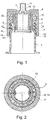
- the lid 7 is constructed in several parts and consists in the embodiment according to FIG. 1 with radially directed ratchet function of a handle part 8 for screwing in and out of the container neck 1 and a nozzle part 2 for engaging the lid 7 in the container neck 1, and a ratchet device 3, on the handle part 8 and nozzle part 2 by means of each other
- Adjacent and interlocking ratchet elements are coupled with the involvement of a spring element such that the Handle part 8 when blocking the neck part 2 in the screwing, after overcoming a first ratchet resistance, due to the elasticity of the material of the neck part 2 and handle part 8, which together makes up the spring element, relative to the neck part 2 in turn, overcoming further ratchet resistance in the screwing is further rotatable.
- the nozzle part 2 surrounds the opening of the container neck 1 and has an inner thread 4 for screwing the lid 7 onto the external thread 11 of the container neck at its inner circumference directed towards the container neck 1. Above the internal thread 4, in the direction of the opening of the container neck 1, this carries Spigot part 2 a seal 5 for sealing between the container neck 1 and cover 7 to prevent the escape of AdBlue.
- the neck part 2 has on its inner circumference a radially encircling groove 12 in which the handle part 8 is non-displaceable in the axial direction and can not be displaced in the circumferential direction, with a spring 13 which completely revolves on its outer circumference or consists of subsections is guided.
- a freewheel with ratchet function between the handle part 8 and neck part 2 is created in the direction of rotation of the lid 7 after its screwing, while in the opening direction of the neck part 2 and handle part 8 by means of the spline 15 positively engage each other and so the thread 4, 11 on the neck part 2 of Cover 7 by turning the handle part 8 in Unscrews opening direction whereby the lid 7 can unscrew from the container neck 1.
- the container is vented.
- the container neck inside end of the neck part 2 is covered with a gas-permeable but liquid-impermeable membrane 10, which is embedded in a further groove 16 in the neck part 2.
- a handle 17 there is an opening 18 with vent connection to the membrane 10th
- FIG. 3 is an embodiment of the lid 7 is shown in cross-section, in which the ratchet device 3 from handle part 8 and nozzle part 2, formed by the latter integrally formed tongues 6, characterized by these surrounding points, as spring elements.
- the material elasticity of the material of the neck part 2 causes the tongues 6 in the radial direction on the handle part 8 fitting, as elastically displaceable extensions, together with the spline on the outer periphery of the handle portion 8, the abutting teeth 14, 15 form, which cooperate so that a Freewheel with ratchet function between handle part 8 and nozzle part 2 in the closing direction of rotation of the lid 7 (arrow 21) is created after its screwing, while in the opening direction of the neck part 2 and handle part 8, due to the stages of the spline and the position of the tongues 6 to form fit interlock and so screwed on the thread on the lid 7 by turning the handle part 8 in the opening direction, causing the lid 7 can unscrew from the container neck 1.
- FIG. 4 a further embodiment of the lid 7 is shown in cross-section, in which the ratchet device 3 is formed from neck part 2 and handle part 8, by integrally formed with the latter elastic rings 6 'as spring elements, one characterized by these surrounding points.
- the material elasticity of the material of the handle part 8 causes the rings 6 'in the radial direction on the neck part 2 fitting, as elastically displaceable extensions, together with the spline on the inner circumference of the neck part 2 form the abutting teeth 14, 15, which cooperate so that a freewheel with ratchet function between handle part 8 and nozzle part 2 in the closing direction of rotation of the lid 7 (arrow 21) is created after its screwing, while in the opening direction of the neck part 2 and handle part 8 due to the stages of the spline 15 and the position of the rings 6 'to form fit interlock and so screwed on the thread on the lid 7 by turning the handle part 8 in the opening direction, causing the lid 7 can unscrew from the container neck 1.
- FIG. 5 is an additional embodiment of the lid 7 is shown in cross section, in which the ratchet device 3 is formed from neck part 2 and handle part 8, by integrally formed with the latter elastic arms 6 "as spring elements, one characterized by this surrounding points 8 causes the arms 6 "in the radial direction on the neck part 2 fitting, as elastically displaceable extensions together with the spline on the inner circumference of the neck part 2, the abutting teeth 14, 15 form, which cooperate so that a Freewheel with ratchet function between handle part 8 and nozzle part 2 in the closing direction of rotation of the lid 7 (arrow 21) is created after its screwing, while in its opening direction spigot part 2 and handle part 8, due to the stages of the spline 15 and the position of the arms 6 "to form fit interlock and so screwed on the thread on the lid 7 by turning the handle part 8 in the opening direction, causing the lid 7 can unscrew from the container neck 1.
Landscapes
- Engineering & Computer Science (AREA)
- Life Sciences & Earth Sciences (AREA)
- Sustainable Development (AREA)
- Sustainable Energy (AREA)
- Chemical & Material Sciences (AREA)
- Combustion & Propulsion (AREA)
- Transportation (AREA)
- Mechanical Engineering (AREA)
- Closures For Containers (AREA)
Abstract
Description
- Die Erfindung bezieht sich auf einen Behälterverschluss mit Ratschenfunktion mit einem Deckel zum Verschließen eines Einfüllstutzens eines Tanks für ein flüssiges Reduktionsmittel, zur Verwendung in einem Kraftfahrzeug in einer Vorrichtung in welcher Stickoxide, die durch die Verbrennung von Kraftstoff in einer Verbrennungskraftmaschine entstanden sind, in Gegenwart des flüssigen Reduktionsmittels zu Stickstoff und Wasser reduziert werden, nach dem Oberbegriff des ersten Anspruchs.
- Aus der
DE 25 54 818 A1 ist ein schraubbarer Verschlussdeckel bekannt, welcher aus einem inneren mit Gewinde versehenen Deckelteil und einem dieses übergreifende äußeren Drehkappenteil besteht, wobei zwischen beiden Teilen ein mittels Druckfeder wirkendes Kupplungsteil zur Begrenzung des Anzugsmomentes für das innere Gewindedeckelteil gegenüber dem äußeren relativ zu diesem drehbeweglich gelagerten Drehkappenteil eingelagert ist. Hierbei wird unter Verwenden eines Federsystems zwischen beiden Deckelteilen im Zusammenwirken mit dem Kupplungsteil zur Drehmomentbegrenzung erreicht, dass das innere Deckel- bzw. äußere Drehkappenteil lediglich drehbeweglich miteinander verbunden sind und gleichzeitig die axiale Spannlagerung beider Teile wie auch des Kupplungsteiles dazwischen gewährleistet ist. Neben Ausführungsformen für die Drehmomentkupplung mit vom inneren Gewindedeckelteil her in ein hohles Drehkappenteil unter Wirkung einer Druckfeder eingreifenden Nockenteilen, bei gleichseitig axialer Spannlagerung beider relativ zueinander verdrehbar gelagerten Teilen, ist auch schon bekannt, zwischen beiden Deckelteilen eine Kupplungsscheibe mittels auf ihrem Randumfang verteilt angeordneten Nocken in entsprechend liegende Aussparungen des äußeren Drehkappenteiles in Axialrichtung nach oben gerichtet eingreifen zu lassen, wobei diese Kupplungsscheibe nach unten gerichtet zwecks Spannlagerung federnd gegen den Boden des inneren Gewindedeckelteiles abgestützt ist. Beim Erreichen eines in Abhängigkeit zur jeweils verwendeten Druckfederkraft vorab bestimmbaren Anzugsmomentes des Schraubverschlussdeckels, entsteht dann ein ratschenartiges Ausklinken der Schrägflächen der Kupplungsteile mit überrasten bei weiter frei drehbar äußerem Kappenteil, so dass der Schraubverschluss niemals zu fest angezogen werden kann, aber jederzeit in umgekehrter Drehrichtung zum Öffnen wiederum leicht zu lösen ist, indem die Nockenansätze mit zur anderen Seite angeordnet senkrechten Flanken vom Boden des Gewindedeckelteiles her sofort wieder in die Kupplungsscheibe axial nach oben zu einklinken als Verbindung zum äußeren Drehkappenteil. - Bei Kraftfahrzeugen werden Verschlussdeckel von Behältern für eine Harnstofflösung zur Abgasbeeinflussung von Dieselmotoren meistens verkleidet hinter schwenkbaren Klappen in der Karosserieoberfläche angeordnet, auch um ein wertiges Erscheinungsbild des Kraftfahrzeugs zu erreichen. Die entsprechenden Einfüllstutzen der Behälter sind dann in der Karosserieaußenhaut festgelegt und die Öffnung der Einfüllstutzen soll sich möglichst nahe der Karosserieaußenhaut hinter der Klappe befinden.
- Verschlussdeckel, wie oben beschrieben, mit Ratschenfunktion besitzen eine Druckfeder und sind deshalb aufwändig gestaltet und beanspruchen deshalb auch viel Einbauraum.
- Der Erfindung hat die Aufgabe, einen Behälterverschluss mit Ratscheneinrichtung mit einem Deckel zum Verschließen eines Einfüllstutzens eines Harnstoffbehälters für ein Kraftfahrzeug bereitzustellen, wobei der Deckel wenig Bauraum beanspruchen und preiswert herstellbar sein soll.
- Die Aufgabe wird erfindungsgemäß durch die kennzeichnenden Merkmale des Anspruchs 1 gelöst. Vorteilhafte Weiterbildungen der Erfindung beschreiben die abhängigen Ansprüche.
- Nach der Erfindung ist ein Behälterverschluss für einen Tank für ein flüssiges Reduktionsmittel, zur Verwendung in einem Kraftfahrzeug in einer Vorrichtung in welcher Stickoxide, die durch die Verbrennung von Kraftstoff in einer Verbrennungskraftmaschine entstanden sind, in Gegenwart des flüssigen Reduktionsmittels zu Stickstoff und Wasser reduziert werden, mit einem Behälterstutzen, der durch einen Deckel verschließbar ist, wobei der Deckel ein Handgriffteil zum Ein- und Ausschrauben in bzw. aus dem Behälterstutzen besitzt und mit einem Stutzenteil, sowie mit einer Ratscheneinrichtung versehen ist, über die Handgriffteil und Stutzenteil mittels aneinander anliegender Verzahnungen derart unter Einbeziehung wenigstens eines Federelements gekoppelt sind, dass das Handgriffteil bei Blockierung des Stutzenteils in Eindrehrichtung, nach Überwindung eines ersten Ratschenwiderstandes aufgrund der Kraft des Federelements, relativ zum Stutzenteil in Eindrehrichtung weiter drehbar ist, dadurch gekennzeichnet, dass das Federelement einstückig mit dem Handgriffteil oder dem Stutzenteil ausgebildet ist.
- Das hat den Vorteil, dass Kosten reduziert werden, im Vergleich mit einem Deckel mit Druckfeder aus Edelstahl. Des Weiteren ermöglichen die Federelemente eine Bauraumersparnis. Zusätzlich können durch entsprechende Federelemente die Lebensdauer und das Drehmoment der Ratsche spezifischer eingestellt werden. Auch kann durch solche Federelemente ein metallisches Klacken der Ratsche vermieden werden.
- Vorteilhafte Ausführungen der Erfindung zeichnen sich dadurch aus, dass das Federelement als elastischer Fortsatz des Stutzenteils zum Handgriffteil hin gerichtet oder des Handgriffteils zum Stutzenteil hin gerichtet ausgebildet ist. Wenn dann der elastische Fortsatz eine Zunge oder ein Ring ist, ist die Ratscheneinrichtung besonders einfach aufgebaut und funktionssicher. Ein Einsatz von drei oder vier Zungen oder Ringen über den Umfang des Stutzenteils oder des Handgriffteils hat sich als besonders vorteilhaft erwiesen. Eine weitere sehr einfache Ausbildung ergibt sich, wenn das Handgriffteil am Stutzenteil verdrehbar festgelegt ist und zusätzlich kann ein Öffnungsrand des Behälterstutzens vom Stutzenteil oder vom Handgriffteil übergriffen werden. Dies stellt eine einfache Verbindung von Handgriffteil und Stutzenteil dar und garantiert eine zuverlässige Funktion des Deckels, der gleichzeitig vorteilhaft formschön ausgebildet werden kann. Dabei kann sich das Federelement oder die Ratscheneinrichtung bei eingeschraubtem Behälterverschluss je nach Bauraumangebot vollständig innerhalb oder teilweise außerhalb des Behälterstutzens befinden.
- Eine gasdurchlässige und flüssigkeitsdichte Membrane, die am Stutzenteil oder am Handgriffteil angebracht ist und den Innenraum des Behälters von der Umgebung abtrennt, stellt sicher, dass der flüssige Inhalt des Behälters nicht durch den Behälterverschluss nach außen ausfließen kann. Dabei kann sich dann die Membrane vollständig innerhalb oder wenigstens teilweise außerhalb des Behälterstutzens befinden.
- Vier Ausführungsbeispiele der Erfindung sind anhand der beigefügten Zeichnung weiter beschrieben. Dabei zeigen:
- Fig. 1:
- einen erfindungsgemäßen Behälterverschluss mit einem Deckel im Längsschnitt in einer ersten Ausführung mit einer Ratscheneinrichtung,
- Fig. 2:
- den erfindungsgemäßen Behälterverschluss aus
Figur 1 im Querschnitt A-A, - Fig. 3:
- einen erfindungsgemäßen Behälterverschluss in schematischer Darstellung mit einem Deckel im Querschnitt in einer zweiten Ausführung mit einer Ratscheneinrichtung mit Federzungen,
- Fig. 4:
- einen erfindungsgemäßen Behälterverschluss in schematischer Darstellung mit einem Deckel im Querschnitt in einer dritten Ausführung mit einer Ratscheneinrichtung mit Federringen und
- Fig. 5:
- einen erfindungsgemäßen Behälterverschluss in schematischer Darstellung mit einem Deckel im Querschnitt in einer vierten Ausführung mit einer Ratscheneinrichtung mit Federarmen.
- Der in den Figuren dargestellte Behälterverschluss für ein Kraftfahrzeug betrifft hier beispielsweise einen nicht gezeichneten Behälter für eine auf Harnstoff basierende Flüssigkeit, die bei der Abgasnachbehandlung für Dieselmotoren zur Reduktion der Stickoxide in einem so genannten SCR-Katalysator verwendet wird. Der Markenname für diese Flüssigkeit ist AdBlue. Der Behälter besitzt einen Behälterstutzen 1 mit einem Außengewinde 11, mittels dessen dieser entweder durch einen Deckel 7 verschließbar oder mit einer nicht gezeichneten Befülleinrichtung mit AdBlue befüllbar ist.
- Der Behälterstutzen 1 befindet sich bei Personenkraftwagen meist hinter einer nicht gezeichneten schwenkbaren Klappe in der Karosserieoberfläche. Der Behälterstutzen 1 ist dann in der Karosserieaußenhaut festgelegt und die Öffnung des Einfüllstutzens 1 liegt möglichst nahe der schwenkbaren Klappe, durch diese verdeckt, dahinter, verschlossen mit dem Deckel 7.
- Der Deckel 7 ist mehrteilig aufgebaut und besteht in der Ausführungsform nach
Figur 1 mit radial gerichteter Ratschenfunktion aus einem Handgriffteil 8 zum Ein- und Ausschrauben in bzw. aus dem Behälterstutzen 1 und einem Stutzenteil 2 für den Eingriff des Deckels 7 in den Behälterstutzen 1, sowie aus einer Ratscheneinrichtung 3, über die Handgriffteil 8 und Stutzenteil 2 mittels aneinander anliegender und ineinandergreifender Ratschenelemente derart unter Einbeziehung eines Federelements gekoppelt sind, dass das Handgriffteil 8 bei Blockierung des Stutzenteils 2 in Eindrehrichtung, nach Überwindung eines ersten Ratschenwiderstandes, aufgrund der Elastizität des Werkstoffs von Stutzenteil 2 und Handgriffteil 8, was zusammen das Federelement ausmacht, relativ zum Stutzenteil 2 in Folge unter Überwindung weiterer Ratschenwiderstände in Eindrehrichtung weiter drehbar ist. - Das Stutzenteil 2 umgreift die Öffnung des Behälterstutzens 1 und besitzt an seinem zum Behälterstutzen 1 hin gerichteten Innenumfang ein Innengewinde 4 zum Aufschrauben des Deckels 7 auf das Außengewinde 11 des Behälterstutzens 1. Oberhalb des Innengewindes 4, in Richtung der Öffnung des Behälterstutzens 1, trägt das Stutzenteil 2 eine Dichtung 5 zur Abdichtung zwischen Behälterstutzen 1 und Deckel 7, um den Austritt von AdBlue zu verhindern. Innerhalb des Behälterstutzens 1 besitzt das Stutzenteil 2 an seinem Innenumfang eine radial umlaufende Nut 12 in der das Handgriffteil 8 mit einer an dessen Außenumfang vollständig umlaufenden oder aus Teilabschnitten bestehenden Feder 13 in der Art einer Nut-Federverbindung in axialer Richtung nicht verschiebbar und in Umfangsrichtung verdrehbar geführt ist.
- Noch weiter innerhalb und vollständig im Behälterstutzen 1 befindet sich die Ratscheneinrichtung 3, durch die zwei keilverzahnte, in radialer Richtung, aufgrund der Werkstoffelastizität der Werkstoffe von Handgriffteil 8 und Stutzenteil 2 elastisch verschiebliche Fortsätze 14 des Handgriffteils 8 in Richtung einer komplementären Keilverzahnung 15 am Innenumfang des Stutzenteils 2 gepresst werden. Dadurch wird ein Freilauf mit Ratschenfunktion zwischen Handgriffteil 8 und Stutzenteil 2 in Schließdrehrichtung des Deckels 7 nach dessen Aufschrauben geschaffen, während in dessen Öffnungsdrehrichtung Stutzenteil 2 und Handgriffteil 8 mittels der Keilverzahnung 15 formschlüssig ineinander greifen und sich so das Gewinde 4, 11 am Stutzenteil 2 des Deckels 7 durch Drehen dessen Handgriffsteils 8 in Öffnungsrichtung aufschraubt wodurch sich der Deckel 7 vom Behälterstutzen 1 abschrauben lässt.
- Über den Deckel 7 im Behälterstutzen 1 wird der Behälter entlüftet. Dazu ist das behälterstutzeninnere Ende des Stutzenteils 2 mit einer gasdurchlässigen aber flüssigkeitsundurchlässigen Membrane 10 abgedeckt, die in eine weitere Nut 16 im Stutzenteil 2 eingelassen ist. Im Handgriffteil 8, verdeckt von einem Handgriff 17, befindet sich eine Öffnung 18 mit Entlüftungsverbindung zur Membrane 10.
- Es entsteht beim Zudrehen des Deckels 7 durch die Ratscheneinrichtung 3 nach Anliegen des Stutzenteils 2 am Öffnungsrand 20 des Behälterstutzens 1 ein Geräusch aufgrund der Relativbewegung der beiden Keilprofile gegeneinander, das sich beim Weiterdrehen wiederholt und der Bedienungsperson durch den schnellen Wechsel von hohem und niedrigem Drehwiderstand auch haptisch anzeigt, dass die Endstellung beim Zuschrauben des Deckels 7 erreicht ist.
- In
Figur 3 ist im Querschnitt eine Ausführungsform des Deckels 7 dargestellt, bei der die Ratscheneinrichtung 3 aus Handgriffteil 8 und Stutzenteil 2, durch mit letzterem einstückig ausgebildete Zungen 6, eine gekennzeichnet durch diese umgebende Punkte, als Federelemente gebildet ist. Die Werkstoffelastizität des Werkstoffs des Stutzenteils 2 bewirkt, dass die Zungen 6 in radialer Richtung am Handgriffteil 8 anliegend, als elastisch verschiebliche Fortsätze, zusammen mit der Keilverzahnung am Außenumfang des Handgriffteils 8 die aneinander anliegenden Verzahnungen 14, 15 bilden, die so zusammenwirken, dass ein Freilauf mit Ratschenfunktion zwischen Handgriffteil 8 und Stutzenteil 2 in Schließdrehrichtung des Deckels 7 (Pfeil 21) nach dessen Aufschrauben geschaffen wird, während in dessen Öffnungsdrehrichtung Stutzenteil 2 und Handgriffteil 8, aufgrund der Stufen der Keilverzahnung und der Stellung der Zungen 6 dazu, formschlüssig ineinander greifen und sich so das Gewinde am Deckel 7 durch Drehen dessen Handgriffsteils 8 in Öffnungsrichtung aufschraubt, wodurch sich der Deckel 7 vom Behälterstutzen 1 abschrauben lässt. - In
Figur 4 ist im Querschnitt eine weitere Ausführungsform des Deckels 7 dargestellt, bei der die Ratscheneinrichtung 3 aus Stutzenteil 2 und Handgriffteil 8 gebildet ist, durch mit letzterem einstückig ausgebildete elastische Ringe 6' als Federelemente, einer gekennzeichnet durch diesen umgebende Punkte. Die Werkstoffelastizität des Werkstoffs des Handgriffteils 8 bewirkt, dass die Ringe 6' in radialer Richtung am Stutzenteil 2 anliegend, als elastisch verschiebliche Fortsätze, zusammen mit der Keilverzahnung am Innenumfang des Stutzenteils 2 die aneinander anliegenden Verzahnungen 14, 15 bilden, die so zusammenwirken, dass ein Freilauf mit Ratschenfunktion zwischen Handgriffteil 8 und Stutzenteil 2 in Schließdrehrichtung des Deckels 7 (Pfeil 21) nach dessen Aufschrauben geschaffen wird, während in dessen Öffnungsdrehrichtung Stutzenteil 2 und Handgriffteil 8 aufgrund der Stufen der Keilverzahnung 15 und der Stellung der Ringe 6' dazu, formschlüssig ineinander greifen und sich so das Gewinde am Deckel 7 durch Drehen dessen Handgriffsteils 8 in Öffnungsrichtung aufschraubt, wodurch sich der Deckel 7 vom Behälterstutzen 1 abschrauben lässt. - In
Figur 5 ist im Querschnitt eine zusätzliche Ausführungsform des Deckels 7 dargestellt, bei der die Ratscheneinrichtung 3 aus Stutzenteil 2 und Handgriffteil 8 gebildet ist, durch mit letzterem einstückig ausgebildete elastische Arme 6" als Federelemente, eines gekennzeichnet durch dieses umgebende Punkte. Die Werkstoffelastizität des Werkstoffs des Handgriffteils 8 bewirkt, dass die Arme 6" in radialer Richtung am Stutzenteil 2 anliegend, als elastisch verschiebliche Fortsätze zusammen mit der Keilverzahnung am Innenumfang des Stutzenteils 2 die aneinander anliegenden Verzahnungen 14, 15 bilden, die so zusammenwirken, dass ein Freilauf mit Ratschenfunktion zwischen Handgriffteil 8 und Stutzenteil 2 in Schließdrehrichtung des Deckels 7 (Pfeil 21) nach dessen Aufschrauben geschaffen wird, während in dessen Öffnungsdrehrichtung Stutzenteil 2 und Handgriffteil 8,aufgrund der Stufen der Keilverzahnung 15 und der Stellung der Arme 6" dazu, formschlüssig ineinander greifen und sich so das Gewinde am Deckel 7 durch Drehen dessen Handgriffsteils 8 in Öffnungsrichtung aufschraubt, wodurch sich der Deckel 7 vom Behälterstutzen 1 abschrauben lässt. - Allen Ausführungsformen ist gemeinsam, dass bei der Relativbewegung zwischen einem stehenden Teil und einem bewegten Teil die Ratsche zum Einsatz kommt. Dabei wird ein Außenteil zu einem Innenteil bewegt oder umgekehrt. Welches der beiden Teile bewegt und welches stehend ist spielt dabei keine Rolle. Die Bewegung wird durch eine elastische Verformung von Federelementen aus z.B. Kunststoff umgesetzt. Die Zahl und Form der Federelemente hat Einfluss auf die Langlebigkeit und das Drehmoment der Ratsche. In
Figur 3 sind die Federelemente Zungen 6, die als Kunststoffstege am Außenteil ausgebildet sind. In denFiguren 4 und 5 sind die Federelemente als Ringe 6' bzw. Arme 6" am Innenteil ausgebildet.
Claims (13)
- Behälterverschluss für einen Tank für ein flüssiges Reduktionsmittel, zur Verwendung in einem Kraftfahrzeug in einer Vorrichtung in welcher Stickoxide, die durch die Verbrennung von Kraftstoff in einer Verbrennungskraftmaschine entstanden sind, in Gegenwart des flüssigen Reduktionsmittels zu Stickstoff und Wasser reduziert werden, mit einem Behälterstutzen (1), der durch einen Deckel (7) verschließbar ist, wobei der Deckel (7) ein Handgriffteil (8) zum Ein- und Ausschrauben in bzw. aus dem Behälterstutzen (1) besitzt und mit einem Stutzenteil (2), sowie mit einer Ratscheneinrichtung (3) versehen ist, über die Handgriffteil (8) und Stutzenteil (2) mittels aneinander anliegender Verzahnungen (14, 15) derart unter Einbeziehung wenigstens eines Federelements gekoppelt sind, dass das Handgriffteil (8) bei Blockierung des Stutzenteils (2) in Eindrehrichtung, nach Überwindung eines ersten Ratschenwiderstandes aufgrund der Kraft des Federelements, relativ zum Stutzenteil (2) in Eindrehrichtung weiter drehbar ist, dadurch gekennzeichnet, dass das Federelement einstückig mit dem Handgriffteil (8) oder dem Stutzenteil (2) ausgebildet ist.
- Behälterverschluss nach Anspruch 1, dadurch gekennzeichnet, dass das Federelement als elastischer Fortsatz des Stutzenteils (2) zum Handgriffteil (8) hin gerichtet oder des Handgriffteils (8) zum Stutzenteil (2) hin gerichtet ausgebildet ist.
- Behälterverschluss nach Anspruch 2, dadurch gekennzeichnet, dass der elastische Fortsatz eine Zunge (6) ist.
- Behälterverschluss nach Anspruch 2, dadurch gekennzeichnet, dass der elastische Fortsatz ein Ring (6') ist.
- Behälterverschluss nach Anspruch 2, dadurch gekennzeichnet, dass der elastische Fortsatz ein Arm (6") ist
- Behälterverschluss nach einem der Ansprüche 1 bis 5, dadurch gekennzeichnet, dass sich das Federelement bei eingeschraubtem Behälterverschluss vollständig innerhalb des Behälterstutzens (1) befindet.
- Behälterverschluss nach einem der Ansprüche 1 bis 5, dadurch gekennzeichnet, dass sich das Federelement bei eingeschraubtem Behälterverschluss wenigstens teilweise außerhalb des Behälterstutzens (1) befindet.
- Behälterverschluss nach einem der Ansprüche 1 bis 5, dadurch gekennzeichnet, dass sich die Ratscheneinrichtung (3) vollständig innerhalb des Behälterstutzens (1) befindet.
- Behälterverschluss nach einem der Ansprüche 1 bis 5, dadurch gekennzeichnet, dass sich die Ratscheneinrichtung (3) wenigstens teilweise außerhalb des Behälterstutzens (1) befindet.
- Behälterverschluss nach einem der Ansprüche 1 bis 9, dadurch gekennzeichnet, dass ein Öffnungsrand (20) des Behälterstutzens (1) vom Stutzenteil (2) oder vom Handgriffteil (8) übergriffen wird und dass das Handgriffteil (8) am Stutzenteil (2) verdrehbar festgelegt ist.
- Behälterverschluss nach einem der Ansprüche 1 bis 10, dadurch gekennzeichnet, dass am Stutzenteil (2) oder am Handgriffteil (8) eine gasdurchlässige und flüssigkeitsdichte Membrane (10) angebracht ist, die den Innenraum des Behälters von der Umgebung abtrennt.
- Behälterverschluss nach Anspruch 11, dadurch gekennzeichnet, dass sich die Membrane (10) vollständig innerhalb des Behälterstutzens (1) befindet.
- Behälterverschluss nach Anspruch 11, dadurch gekennzeichnet, dass sich die Membrane (10) wenigstens teilweise außerhalb des Behälterstutzens (1) befindet.
Applications Claiming Priority (1)
| Application Number | Priority Date | Filing Date | Title |
|---|---|---|---|
| DE102016201799.3A DE102016201799A1 (de) | 2016-02-05 | 2016-02-05 | Behälterverschluss mit Ratschenfunktion |
Publications (2)
| Publication Number | Publication Date |
|---|---|
| EP3202609A1 true EP3202609A1 (de) | 2017-08-09 |
| EP3202609B1 EP3202609B1 (de) | 2021-03-31 |
Family
ID=57868064
Family Applications (1)
| Application Number | Title | Priority Date | Filing Date |
|---|---|---|---|
| EP17152092.7A Active EP3202609B1 (de) | 2016-02-05 | 2017-01-19 | Behälterverschluss mit ratschenfunktion |
Country Status (2)
| Country | Link |
|---|---|
| EP (1) | EP3202609B1 (de) |
| DE (1) | DE102016201799A1 (de) |
Citations (4)
| Publication number | Priority date | Publication date | Assignee | Title |
|---|---|---|---|---|
| DE2554818A1 (de) | 1969-12-03 | 1977-06-23 | Blau Kg Kraftfahrzeugtech | Schraub-verschlussdeckel mit begrenzung seines anzug-drehmomentes auf einem behaelter- oder rohr-stutzen |
| US20090223959A1 (en) * | 2008-03-07 | 2009-09-10 | Schulz William J | Cap for a fluid container |
| EP2492128A1 (de) * | 2011-02-22 | 2012-08-29 | Inergy Automotive Systems Research (Société Anonyme) | Ammoniak-Vorläufer-Aufbewahrungssystem mit semipermeabler Membran |
| US20130001229A1 (en) * | 2011-06-02 | 2013-01-03 | Chongqing Zongshen General Power Machine Co., Ltd. | Universal gasoline engine fuel tank cover |
Family Cites Families (4)
| Publication number | Priority date | Publication date | Assignee | Title |
|---|---|---|---|---|
| US516032A (en) * | 1894-03-06 | Submarine-drilling apparatus | ||
| BE759689A (fr) * | 1969-12-03 | 1971-05-17 | Blau Werner | Couvercle filete a couple de serrage limite pour recipients ou tubulures |
| FR2954428B1 (fr) * | 2009-12-21 | 2012-04-20 | Itw De France | Dispositif limiteur de couple et bouchon pour tete de tubulure comportant un tel dispositif |
| DE102015105675B3 (de) * | 2015-04-14 | 2016-09-15 | Reutter Gmbh | Tankdeckel, insbesondere SCR-Verschluss |
-
2016
- 2016-02-05 DE DE102016201799.3A patent/DE102016201799A1/de not_active Withdrawn
-
2017
- 2017-01-19 EP EP17152092.7A patent/EP3202609B1/de active Active
Patent Citations (4)
| Publication number | Priority date | Publication date | Assignee | Title |
|---|---|---|---|---|
| DE2554818A1 (de) | 1969-12-03 | 1977-06-23 | Blau Kg Kraftfahrzeugtech | Schraub-verschlussdeckel mit begrenzung seines anzug-drehmomentes auf einem behaelter- oder rohr-stutzen |
| US20090223959A1 (en) * | 2008-03-07 | 2009-09-10 | Schulz William J | Cap for a fluid container |
| EP2492128A1 (de) * | 2011-02-22 | 2012-08-29 | Inergy Automotive Systems Research (Société Anonyme) | Ammoniak-Vorläufer-Aufbewahrungssystem mit semipermeabler Membran |
| US20130001229A1 (en) * | 2011-06-02 | 2013-01-03 | Chongqing Zongshen General Power Machine Co., Ltd. | Universal gasoline engine fuel tank cover |
Also Published As
| Publication number | Publication date |
|---|---|
| DE102016201799A1 (de) | 2017-08-10 |
| EP3202609B1 (de) | 2021-03-31 |
Similar Documents
| Publication | Publication Date | Title |
|---|---|---|
| DE2357789C3 (de) | Verschlußkappe für das Verschließen von einen Füllstutzen mit Innengewinde aufweisenden Behältern | |
| EP0080624B1 (de) | Verschlussdeckel, insbesondere für einen Kraftstofftank | |
| EP1979265B1 (de) | Verbindungsbaugruppe zur verbindung eines ausgangsbehälters und eines zielbehälters | |
| EP2444604B1 (de) | Aufnahmebehältnis für ein Fluid, insbesondere Motorölwanne oder Getriebeölwanne für ein KFZ | |
| DE2500852C2 (de) | Verschlußkappe für den Füllstutzen eines Tanks | |
| DE10125037B4 (de) | Tankverschluß | |
| EP2910289A1 (de) | Filtereinrichtung | |
| EP2445605A1 (de) | Filtereinrichtung | |
| DE2553881C2 (de) | ||
| WO2012139631A1 (de) | Einfüllstutzen für einen flüssigkeitstank, insbesondere harnstofftank an kraftfahrzeugen | |
| DE102014207652A1 (de) | Behälterverschluss | |
| DE102012008418B4 (de) | Adapter für einen Öleinfüllstutzen und Montageverfahren des Adapters | |
| DE202010008751U1 (de) | Automatische Verschlussvorrichtung für Kraftstofftanks | |
| WO2006066294A1 (de) | Deckelloser einfüllstutzen für den tank eines kraftfahrzeuges | |
| DE102014224905A1 (de) | Behälterverschluss mit Ratscheneinrichtung | |
| EP0943477B1 (de) | Kraftstoffbehälterverschluss | |
| EP3202609B1 (de) | Behälterverschluss mit ratschenfunktion | |
| DE3838450A1 (de) | Verschlussdeckel fuer einen kraftstofftank | |
| EP0102083B1 (de) | Selbstschliessender Kraftstoffbehälterverschluss | |
| DE102014106047A1 (de) | Tank- oder Lademulde für ein Kraftfahrzeug | |
| DE102008038052A1 (de) | Dichtungsanordnung | |
| DE1962187C3 (de) | Aufschraubbarer Verschlußdeckel | |
| DE102018208468A1 (de) | Verschlussstopfen, Fluidbehälter und Fluidbehälterbaugruppe | |
| DE102007043991A1 (de) | Tankdeckel | |
| EP1138540A2 (de) | Einfüllstutzen |
Legal Events
| Date | Code | Title | Description |
|---|---|---|---|
| PUAI | Public reference made under article 153(3) epc to a published international application that has entered the european phase |
Free format text: ORIGINAL CODE: 0009012 |
|
| STAA | Information on the status of an ep patent application or granted ep patent |
Free format text: STATUS: THE APPLICATION HAS BEEN PUBLISHED |
|
| AK | Designated contracting states |
Kind code of ref document: A1 Designated state(s): AL AT BE BG CH CY CZ DE DK EE ES FI FR GB GR HR HU IE IS IT LI LT LU LV MC MK MT NL NO PL PT RO RS SE SI SK SM TR |
|
| AX | Request for extension of the european patent |
Extension state: BA ME |
|
| STAA | Information on the status of an ep patent application or granted ep patent |
Free format text: STATUS: REQUEST FOR EXAMINATION WAS MADE |
|
| 17P | Request for examination filed |
Effective date: 20180131 |
|
| RBV | Designated contracting states (corrected) |
Designated state(s): AL AT BE BG CH CY CZ DE DK EE ES FI FR GB GR HR HU IE IS IT LI LT LU LV MC MK MT NL NO PL PT RO RS SE SI SK SM TR |
|
| STAA | Information on the status of an ep patent application or granted ep patent |
Free format text: STATUS: EXAMINATION IS IN PROGRESS |
|
| 17Q | First examination report despatched |
Effective date: 20200219 |
|
| GRAP | Despatch of communication of intention to grant a patent |
Free format text: ORIGINAL CODE: EPIDOSNIGR1 |
|
| STAA | Information on the status of an ep patent application or granted ep patent |
Free format text: STATUS: GRANT OF PATENT IS INTENDED |
|
| INTG | Intention to grant announced |
Effective date: 20201106 |
|
| GRAS | Grant fee paid |
Free format text: ORIGINAL CODE: EPIDOSNIGR3 |
|
| GRAA | (expected) grant |
Free format text: ORIGINAL CODE: 0009210 |
|
| STAA | Information on the status of an ep patent application or granted ep patent |
Free format text: STATUS: THE PATENT HAS BEEN GRANTED |
|
| AK | Designated contracting states |
Kind code of ref document: B1 Designated state(s): AL AT BE BG CH CY CZ DE DK EE ES FI FR GB GR HR HU IE IS IT LI LT LU LV MC MK MT NL NO PL PT RO RS SE SI SK SM TR |
|
| REG | Reference to a national code |
Ref country code: GB Ref legal event code: FG4D Free format text: NOT ENGLISH Ref country code: CH Ref legal event code: EP |
|
| REG | Reference to a national code |
Ref country code: DE Ref legal event code: R096 Ref document number: 502017009854 Country of ref document: DE Ref country code: AT Ref legal event code: REF Ref document number: 1376554 Country of ref document: AT Kind code of ref document: T Effective date: 20210415 |
|
| REG | Reference to a national code |
Ref country code: IE Ref legal event code: FG4D Free format text: LANGUAGE OF EP DOCUMENT: GERMAN |
|
| REG | Reference to a national code |
Ref country code: LT Ref legal event code: MG9D |
|
| PG25 | Lapsed in a contracting state [announced via postgrant information from national office to epo] |
Ref country code: FI Free format text: LAPSE BECAUSE OF FAILURE TO SUBMIT A TRANSLATION OF THE DESCRIPTION OR TO PAY THE FEE WITHIN THE PRESCRIBED TIME-LIMIT Effective date: 20210331 Ref country code: HR Free format text: LAPSE BECAUSE OF FAILURE TO SUBMIT A TRANSLATION OF THE DESCRIPTION OR TO PAY THE FEE WITHIN THE PRESCRIBED TIME-LIMIT Effective date: 20210331 Ref country code: NO Free format text: LAPSE BECAUSE OF FAILURE TO SUBMIT A TRANSLATION OF THE DESCRIPTION OR TO PAY THE FEE WITHIN THE PRESCRIBED TIME-LIMIT Effective date: 20210630 Ref country code: BG Free format text: LAPSE BECAUSE OF FAILURE TO SUBMIT A TRANSLATION OF THE DESCRIPTION OR TO PAY THE FEE WITHIN THE PRESCRIBED TIME-LIMIT Effective date: 20210630 |
|
| PG25 | Lapsed in a contracting state [announced via postgrant information from national office to epo] |
Ref country code: SE Free format text: LAPSE BECAUSE OF FAILURE TO SUBMIT A TRANSLATION OF THE DESCRIPTION OR TO PAY THE FEE WITHIN THE PRESCRIBED TIME-LIMIT Effective date: 20210331 Ref country code: LV Free format text: LAPSE BECAUSE OF FAILURE TO SUBMIT A TRANSLATION OF THE DESCRIPTION OR TO PAY THE FEE WITHIN THE PRESCRIBED TIME-LIMIT Effective date: 20210331 Ref country code: RS Free format text: LAPSE BECAUSE OF FAILURE TO SUBMIT A TRANSLATION OF THE DESCRIPTION OR TO PAY THE FEE WITHIN THE PRESCRIBED TIME-LIMIT Effective date: 20210331 |
|
| REG | Reference to a national code |
Ref country code: NL Ref legal event code: MP Effective date: 20210331 |
|
| PG25 | Lapsed in a contracting state [announced via postgrant information from national office to epo] |
Ref country code: SM Free format text: LAPSE BECAUSE OF FAILURE TO SUBMIT A TRANSLATION OF THE DESCRIPTION OR TO PAY THE FEE WITHIN THE PRESCRIBED TIME-LIMIT Effective date: 20210331 Ref country code: NL Free format text: LAPSE BECAUSE OF FAILURE TO SUBMIT A TRANSLATION OF THE DESCRIPTION OR TO PAY THE FEE WITHIN THE PRESCRIBED TIME-LIMIT Effective date: 20210331 Ref country code: LT Free format text: LAPSE BECAUSE OF FAILURE TO SUBMIT A TRANSLATION OF THE DESCRIPTION OR TO PAY THE FEE WITHIN THE PRESCRIBED TIME-LIMIT Effective date: 20210331 Ref country code: EE Free format text: LAPSE BECAUSE OF FAILURE TO SUBMIT A TRANSLATION OF THE DESCRIPTION OR TO PAY THE FEE WITHIN THE PRESCRIBED TIME-LIMIT Effective date: 20210331 Ref country code: CZ Free format text: LAPSE BECAUSE OF FAILURE TO SUBMIT A TRANSLATION OF THE DESCRIPTION OR TO PAY THE FEE WITHIN THE PRESCRIBED TIME-LIMIT Effective date: 20210331 |
|
| PG25 | Lapsed in a contracting state [announced via postgrant information from national office to epo] |
Ref country code: IS Free format text: LAPSE BECAUSE OF FAILURE TO SUBMIT A TRANSLATION OF THE DESCRIPTION OR TO PAY THE FEE WITHIN THE PRESCRIBED TIME-LIMIT Effective date: 20210731 Ref country code: PL Free format text: LAPSE BECAUSE OF FAILURE TO SUBMIT A TRANSLATION OF THE DESCRIPTION OR TO PAY THE FEE WITHIN THE PRESCRIBED TIME-LIMIT Effective date: 20210331 Ref country code: PT Free format text: LAPSE BECAUSE OF FAILURE TO SUBMIT A TRANSLATION OF THE DESCRIPTION OR TO PAY THE FEE WITHIN THE PRESCRIBED TIME-LIMIT Effective date: 20210802 Ref country code: SK Free format text: LAPSE BECAUSE OF FAILURE TO SUBMIT A TRANSLATION OF THE DESCRIPTION OR TO PAY THE FEE WITHIN THE PRESCRIBED TIME-LIMIT Effective date: 20210331 Ref country code: RO Free format text: LAPSE BECAUSE OF FAILURE TO SUBMIT A TRANSLATION OF THE DESCRIPTION OR TO PAY THE FEE WITHIN THE PRESCRIBED TIME-LIMIT Effective date: 20210331 |
|
| REG | Reference to a national code |
Ref country code: DE Ref legal event code: R097 Ref document number: 502017009854 Country of ref document: DE |
|
| PG25 | Lapsed in a contracting state [announced via postgrant information from national office to epo] |
Ref country code: ES Free format text: LAPSE BECAUSE OF FAILURE TO SUBMIT A TRANSLATION OF THE DESCRIPTION OR TO PAY THE FEE WITHIN THE PRESCRIBED TIME-LIMIT Effective date: 20210331 Ref country code: DK Free format text: LAPSE BECAUSE OF FAILURE TO SUBMIT A TRANSLATION OF THE DESCRIPTION OR TO PAY THE FEE WITHIN THE PRESCRIBED TIME-LIMIT Effective date: 20210331 Ref country code: AL Free format text: LAPSE BECAUSE OF FAILURE TO SUBMIT A TRANSLATION OF THE DESCRIPTION OR TO PAY THE FEE WITHIN THE PRESCRIBED TIME-LIMIT Effective date: 20210331 |
|
| PLBE | No opposition filed within time limit |
Free format text: ORIGINAL CODE: 0009261 |
|
| STAA | Information on the status of an ep patent application or granted ep patent |
Free format text: STATUS: NO OPPOSITION FILED WITHIN TIME LIMIT |
|
| 26N | No opposition filed |
Effective date: 20220104 |
|
| PG25 | Lapsed in a contracting state [announced via postgrant information from national office to epo] |
Ref country code: IS Free format text: LAPSE BECAUSE OF FAILURE TO SUBMIT A TRANSLATION OF THE DESCRIPTION OR TO PAY THE FEE WITHIN THE PRESCRIBED TIME-LIMIT Effective date: 20210731 |
|
| PG25 | Lapsed in a contracting state [announced via postgrant information from national office to epo] |
Ref country code: MC Free format text: LAPSE BECAUSE OF FAILURE TO SUBMIT A TRANSLATION OF THE DESCRIPTION OR TO PAY THE FEE WITHIN THE PRESCRIBED TIME-LIMIT Effective date: 20210331 |
|
| REG | Reference to a national code |
Ref country code: CH Ref legal event code: PL |
|
| REG | Reference to a national code |
Ref country code: BE Ref legal event code: MM Effective date: 20220131 |
|
| PG25 | Lapsed in a contracting state [announced via postgrant information from national office to epo] |
Ref country code: LU Free format text: LAPSE BECAUSE OF NON-PAYMENT OF DUE FEES Effective date: 20220119 |
|
| PG25 | Lapsed in a contracting state [announced via postgrant information from national office to epo] |
Ref country code: BE Free format text: LAPSE BECAUSE OF NON-PAYMENT OF DUE FEES Effective date: 20220131 |
|
| PG25 | Lapsed in a contracting state [announced via postgrant information from national office to epo] |
Ref country code: LI Free format text: LAPSE BECAUSE OF NON-PAYMENT OF DUE FEES Effective date: 20220131 Ref country code: CH Free format text: LAPSE BECAUSE OF NON-PAYMENT OF DUE FEES Effective date: 20220131 |
|
| PG25 | Lapsed in a contracting state [announced via postgrant information from national office to epo] |
Ref country code: IE Free format text: LAPSE BECAUSE OF NON-PAYMENT OF DUE FEES Effective date: 20220119 |
|
| REG | Reference to a national code |
Ref country code: AT Ref legal event code: MM01 Ref document number: 1376554 Country of ref document: AT Kind code of ref document: T Effective date: 20220119 |
|
| PG25 | Lapsed in a contracting state [announced via postgrant information from national office to epo] |
Ref country code: AT Free format text: LAPSE BECAUSE OF NON-PAYMENT OF DUE FEES Effective date: 20220119 |
|
| P01 | Opt-out of the competence of the unified patent court (upc) registered |
Effective date: 20230503 |
|
| PG25 | Lapsed in a contracting state [announced via postgrant information from national office to epo] |
Ref country code: HU Free format text: LAPSE BECAUSE OF FAILURE TO SUBMIT A TRANSLATION OF THE DESCRIPTION OR TO PAY THE FEE WITHIN THE PRESCRIBED TIME-LIMIT; INVALID AB INITIO Effective date: 20170119 |
|
| PG25 | Lapsed in a contracting state [announced via postgrant information from national office to epo] |
Ref country code: MK Free format text: LAPSE BECAUSE OF FAILURE TO SUBMIT A TRANSLATION OF THE DESCRIPTION OR TO PAY THE FEE WITHIN THE PRESCRIBED TIME-LIMIT Effective date: 20210331 Ref country code: CY Free format text: LAPSE BECAUSE OF FAILURE TO SUBMIT A TRANSLATION OF THE DESCRIPTION OR TO PAY THE FEE WITHIN THE PRESCRIBED TIME-LIMIT Effective date: 20210331 |
|
| PG25 | Lapsed in a contracting state [announced via postgrant information from national office to epo] |
Ref country code: MT Free format text: LAPSE BECAUSE OF FAILURE TO SUBMIT A TRANSLATION OF THE DESCRIPTION OR TO PAY THE FEE WITHIN THE PRESCRIBED TIME-LIMIT Effective date: 20210331 |
|
| PG25 | Lapsed in a contracting state [announced via postgrant information from national office to epo] |
Ref country code: GR Free format text: LAPSE BECAUSE OF NON-PAYMENT OF DUE FEES Effective date: 20210331 |
|
| PG25 | Lapsed in a contracting state [announced via postgrant information from national office to epo] |
Ref country code: GR Free format text: LAPSE BECAUSE OF NON-PAYMENT OF DUE FEES Effective date: 20210331 |
|
| PG25 | Lapsed in a contracting state [announced via postgrant information from national office to epo] |
Ref country code: TR Free format text: LAPSE BECAUSE OF FAILURE TO SUBMIT A TRANSLATION OF THE DESCRIPTION OR TO PAY THE FEE WITHIN THE PRESCRIBED TIME-LIMIT Effective date: 20210331 |
|
| PGFP | Annual fee paid to national office [announced via postgrant information from national office to epo] |
Ref country code: GB Payment date: 20260122 Year of fee payment: 10 |
|
| PGFP | Annual fee paid to national office [announced via postgrant information from national office to epo] |
Ref country code: DE Payment date: 20260121 Year of fee payment: 10 |
|
| PGFP | Annual fee paid to national office [announced via postgrant information from national office to epo] |
Ref country code: IT Payment date: 20260130 Year of fee payment: 10 |
|
| PGFP | Annual fee paid to national office [announced via postgrant information from national office to epo] |
Ref country code: FR Payment date: 20260121 Year of fee payment: 10 |