EP3202559A1 - Three-dimensional shaping apparatus, method for controlling a three-dimensional shaping apparatus, and program - Google Patents
Three-dimensional shaping apparatus, method for controlling a three-dimensional shaping apparatus, and program Download PDFInfo
- Publication number
- EP3202559A1 EP3202559A1 EP16204062.0A EP16204062A EP3202559A1 EP 3202559 A1 EP3202559 A1 EP 3202559A1 EP 16204062 A EP16204062 A EP 16204062A EP 3202559 A1 EP3202559 A1 EP 3202559A1
- Authority
- EP
- European Patent Office
- Prior art keywords
- layer
- shaping
- powder
- thickness
- liquid
- Prior art date
- Legal status (The legal status is an assumption and is not a legal conclusion. Google has not performed a legal analysis and makes no representation as to the accuracy of the status listed.)
- Granted
Links
Images


Classifications
-
- B—PERFORMING OPERATIONS; TRANSPORTING
- B29—WORKING OF PLASTICS; WORKING OF SUBSTANCES IN A PLASTIC STATE IN GENERAL
- B29C—SHAPING OR JOINING OF PLASTICS; SHAPING OF MATERIAL IN A PLASTIC STATE, NOT OTHERWISE PROVIDED FOR; AFTER-TREATMENT OF THE SHAPED PRODUCTS, e.g. REPAIRING
- B29C64/00—Additive manufacturing, i.e. manufacturing of three-dimensional [3D] objects by additive deposition, additive agglomeration or additive layering, e.g. by 3D printing, stereolithography or selective laser sintering
- B29C64/10—Processes of additive manufacturing
- B29C64/165—Processes of additive manufacturing using a combination of solid and fluid materials, e.g. a powder selectively bound by a liquid binder, catalyst, inhibitor or energy absorber
-
- B—PERFORMING OPERATIONS; TRANSPORTING
- B33—ADDITIVE MANUFACTURING TECHNOLOGY
- B33Y—ADDITIVE MANUFACTURING, i.e. MANUFACTURING OF THREE-DIMENSIONAL [3-D] OBJECTS BY ADDITIVE DEPOSITION, ADDITIVE AGGLOMERATION OR ADDITIVE LAYERING, e.g. BY 3-D PRINTING, STEREOLITHOGRAPHY OR SELECTIVE LASER SINTERING
- B33Y50/00—Data acquisition or data processing for additive manufacturing
- B33Y50/02—Data acquisition or data processing for additive manufacturing for controlling or regulating additive manufacturing processes
-
- B—PERFORMING OPERATIONS; TRANSPORTING
- B29—WORKING OF PLASTICS; WORKING OF SUBSTANCES IN A PLASTIC STATE IN GENERAL
- B29C—SHAPING OR JOINING OF PLASTICS; SHAPING OF MATERIAL IN A PLASTIC STATE, NOT OTHERWISE PROVIDED FOR; AFTER-TREATMENT OF THE SHAPED PRODUCTS, e.g. REPAIRING
- B29C64/00—Additive manufacturing, i.e. manufacturing of three-dimensional [3D] objects by additive deposition, additive agglomeration or additive layering, e.g. by 3D printing, stereolithography or selective laser sintering
- B29C64/30—Auxiliary operations or equipment
- B29C64/386—Data acquisition or data processing for additive manufacturing
- B29C64/393—Data acquisition or data processing for additive manufacturing for controlling or regulating additive manufacturing processes
-
- B—PERFORMING OPERATIONS; TRANSPORTING
- B33—ADDITIVE MANUFACTURING TECHNOLOGY
- B33Y—ADDITIVE MANUFACTURING, i.e. MANUFACTURING OF THREE-DIMENSIONAL [3-D] OBJECTS BY ADDITIVE DEPOSITION, ADDITIVE AGGLOMERATION OR ADDITIVE LAYERING, e.g. BY 3-D PRINTING, STEREOLITHOGRAPHY OR SELECTIVE LASER SINTERING
- B33Y30/00—Apparatus for additive manufacturing; Details thereof or accessories therefor
-
- B—PERFORMING OPERATIONS; TRANSPORTING
- B29—WORKING OF PLASTICS; WORKING OF SUBSTANCES IN A PLASTIC STATE IN GENERAL
- B29K—INDEXING SCHEME ASSOCIATED WITH SUBCLASSES B29B, B29C OR B29D, RELATING TO MOULDING MATERIALS OR TO MATERIALS FOR MOULDS, REINFORCEMENTS, FILLERS OR PREFORMED PARTS, e.g. INSERTS
- B29K2105/00—Condition, form or state of moulded material or of the material to be shaped
- B29K2105/0058—Liquid or visquous
-
- B—PERFORMING OPERATIONS; TRANSPORTING
- B29—WORKING OF PLASTICS; WORKING OF SUBSTANCES IN A PLASTIC STATE IN GENERAL
- B29K—INDEXING SCHEME ASSOCIATED WITH SUBCLASSES B29B, B29C OR B29D, RELATING TO MOULDING MATERIALS OR TO MATERIALS FOR MOULDS, REINFORCEMENTS, FILLERS OR PREFORMED PARTS, e.g. INSERTS
- B29K2105/00—Condition, form or state of moulded material or of the material to be shaped
- B29K2105/25—Solid
- B29K2105/251—Particles, powder or granules
-
- B—PERFORMING OPERATIONS; TRANSPORTING
- B33—ADDITIVE MANUFACTURING TECHNOLOGY
- B33Y—ADDITIVE MANUFACTURING, i.e. MANUFACTURING OF THREE-DIMENSIONAL [3-D] OBJECTS BY ADDITIVE DEPOSITION, ADDITIVE AGGLOMERATION OR ADDITIVE LAYERING, e.g. BY 3-D PRINTING, STEREOLITHOGRAPHY OR SELECTIVE LASER SINTERING
- B33Y10/00—Processes of additive manufacturing
-
- B—PERFORMING OPERATIONS; TRANSPORTING
- B33—ADDITIVE MANUFACTURING TECHNOLOGY
- B33Y—ADDITIVE MANUFACTURING, i.e. MANUFACTURING OF THREE-DIMENSIONAL [3-D] OBJECTS BY ADDITIVE DEPOSITION, ADDITIVE AGGLOMERATION OR ADDITIVE LAYERING, e.g. BY 3-D PRINTING, STEREOLITHOGRAPHY OR SELECTIVE LASER SINTERING
- B33Y50/00—Data acquisition or data processing for additive manufacturing
Definitions
- the present invention relates to a three-dimensional shaping apparatus, a method for controlling a three-dimensional shaping apparatus, and a program.
- a powder lamination shaping method of a binder-jet type As a method for manufacturing a three-dimensional shaped object, a powder lamination shaping method of a binder-jet type is known. According to this shaping method, a step of supplying material powder to the inside of a container in a predetermined amount at a time so as to form a powder layer and a step of discharging shaping liquid that solidifies the powder onto the powder so as to solidify a predetermined part thereof are repeatedly performed to manufacture the intended three-dimensional shaped object in the container.
- a disclosed apparatus is configured to form a base layer of a overhung part in a (k+1)th layer during a bonding step of a k-th layer, for the purpose of preventing bonding liquid (shaping liquid) from permeating into a lower layer when the overhung part is formed (Japanese Patent No. 5,471,939 ).
- the density of the powder is increased by the liquid bridge force of the shaping liquid, so that the thickness of the powder layer is reduced.
- an error may occur in the length or the shape of the intended three-dimensional shaped object, also in locations other than the overhung part such as, for example, the bottom face of the shaped object.
- a three-dimensional shaping apparatus includes a storage unit, a supplying unit, a discharging unit, and a controlling unit.
- the storage unit is configured to store powder.
- the supplying unit is configured to supply the powder to the storage unit to form a layer of the powder.
- the discharging unit is configured to discharge shaping liquid to solidify the powder onto the powder.
- the controlling unit is configured to generate a control signal for controlling the supplying unit and the discharging unit based on shaping data indicating a shape of a three-dimensional shaped object.
- the controlling unit is configured to generate the control signal for laminating at least one sacrificial layer separable from at least one shaping layer corresponding to the three-dimensional shaped object in such a position that the at least one sacrificial layer is under the at least one shaping layer, prior to laminating the at least one shaping layer, based on the shaping data and powder information stored in advance and indicating change in thickness of a layer of the powder caused by permeation of the shaping liquid.
- FIG. 1 is a diagram for explaining an overview of an exemplary hardware configuration of a three-dimensional shaping system according to an embodiment.
- a three-dimensional shaping system 1 includes a three-dimensional shaping apparatus (hereinafter, simply “shaping apparatus") 11, an information processing terminal 12, and a network 13.
- the shaping apparatus 11 is an apparatus configured to form a three-dimensional shaped object having an arbitrary shape by a powder lamination shaping method of a binder-jet type to.
- a powder lamination shaping method of the binder-jet type a step of supplying material powder to the inside of a container in a predetermined amount at a time so as to form a powder layer and a step of discharging shaping liquid that solidifies the powder onto the powder so as to solidify a predetermined part thereof are repeatedly performed to manufacture the intended three-dimensional shaped object in the container.
- the information processing terminal 12 is an apparatus configured to generate a control signal for controlling the shaping apparatus 11.
- the information processing terminal 12 may be, for example, a general-purpose computer, a tablet, a smartphone, or the like provided with a Micro Processing Unit (MPU), a Read-Only Memory (ROM), a Random Access Memory (RAM), and an external storage device configured with a semiconductor memory device or the like.
- MPU Micro Processing Unit
- ROM Read-Only Memory
- RAM Random Access Memory
- possible embodiments of the information processing terminal 12 are not limited to these examples.
- the network 13 is a computer network that is either well-known or novel and makes it possible for the shaping apparatus 11 and the information processing terminal 12 to transmit and receive signals to and from each other, while ensuring a communication speed required for controlling processes.
- FIG. 1 illustrates the example in which the single shaping apparatus 11 and the single information processing terminal 12 are connected to each other via the network 13, two or more shaping apparatuses 11 and/or two or more information processing terminals 12 may be provided.
- FIG. 2 is a top view of an exemplary hardware configuration of a shaping apparatus according to a first aspect.
- FIG. 3 is an exemplary lateral view of a part of the hardware configuration of the shaping apparatus according to the first aspect.
- FIG. 4 is an exemplary perspective view of a part of the hardware configuration of the shaping apparatus according to the first aspect.
- FIG. 5 is a view for explaining an exemplary operational state of the shaping apparatus according to the first aspect.
- the shaping apparatus 11 includes a storage unit 21, a supplying unit 22, a shaping liquid reservoir unit 23, a discharging unit 24, and a maintenance unit 25.
- the storage unit 21 is a unit configured to store therein powder 27 for forming the three-dimensional shaped object.
- the storage unit 21 includes a shaping chamber 31, a shaping stage 32, and a roller 33.
- the shaping chamber 31 is a member configured to store therein the powder 27 supplied thereto from the supplying unit 22 (explained later) and to have the three-dimensional shaped object formed in the inside thereof.
- the shaping stage 32 is a member positioned at the bottom of the shaping chamber 31 and is configured to move in the Z-direction.
- the volume of the shaping chamber 31 changes as a result of raising and lowering the shaping stage 32.
- the shaping stage 32 is lowered as the number of layers of the powder 27 increases.
- the roller 33 is a member configured to flatten the surface of the powder 27 supplied from the supplying unit 22 to the inside of the shaping chamber 31.
- the roller 33 is configured to move in the X-direction and also to rotate.
- the supplying unit 22 is a unit configured to supply the powder 27 to the storage unit 21 (the shaping chamber 31) and includes a storing container 47 and a shutter 42.
- the storing container 41 is a container configured to store the powder 27 therein.
- An opening 43 is formed in a lower end part of the storing container 41.
- the storing container 41 is fixed to a carriage 61 of the discharging unit 24 (explained later) and is configured to move together with the carriage 61.
- the shutter 42 is a member configured to open and close the opening 43 of the storing container 41.
- the amount of the powder 27 supplied to the shaping chamber 31 is adjusted according to the time period during which the shutter 42 is open.
- the shaping liquid reservoir unit 23 is a unit configured to store therein shaping liquid 55 that solidifies the powder 27.
- the shaping liquid reservoir unit 23 includes a tank attaching member 51 and tanks 52.
- the tank attaching member 51 is a member configured to detachably fix the tanks 52.
- the tanks 52 are each a member configured to store the shaping liquid 55 on the inside thereof.
- the plurality of tanks 52 are installed, and mutually-different types of shaping liquid 55 may be stored in the tanks 52.
- the shaping liquid include a liquid the main component of which is water and that contains any of the following: an aqueous medium containing alcohol, ether, ketone, and/or the like; aliphatic hydrocarbons; an ether-based solvent such as glycol ether; an ester-based solvent such as ethyl acetate; a ketone-based solvent such as methyl ethyl ketone; and a higher alcohol; however, possible embodiments are not limited to these examples.
- the inside of each of the tanks 52 is in communication with discharging heads 62 of the discharging unit 24 (explained later) via passages (not illustrated).
- the discharging unit 24 is a unit configured to discharge the shaping liquid 55 onto the powder 27 provided in the storage unit 21 (the shaping chamber 31).
- the discharging unit 24 includes the carriage 61 and the discharging heads 62.
- the carriage 61 is a member configured to fix the supplying unit 22 and the discharging heads 62.
- the carriage 61 is linked to first rails 71 installed in parallel to the X-direction and is configured to move (to change the position thereof) along the first rails 71 (in the X-direction).
- the two ends of each of the first rails 71 are fixed to lateral plates 72.
- the lateral plates 72 are fixed to sliders 73.
- the sliders 73 are linked to second rails 74 installed in parallel to the Y-direction and are configured to move (to change the position thereof) along the second rails 74 (in the Y-direction).
- the second rails 74 are configured to move in the Z-direction.
- the carriage 61 is capable of moving in a three-dimensional manner. As the carriage 61 moves, the supplying unit 22 and the discharging heads 62 fixed to the carriage 61 also move.
- the discharging heads 62 are each a member configured to discharge the shaping liquid 55 stored in the tanks 52 toward the powder 27 provided in the shaping chamber 31.
- the discharging heads 62 each including a plurality of nozzles 64 directed downward.
- the discharging heads 62 and the tanks 52 are in communication with each other via passages (not illustrated). In the present example, two discharging heads 62 are provided.
- the discharging heads 62 may discharge mutually-different types of shaping liquid 55.
- the maintenance unit 25 is a unit configured to perform maintenance on the discharging unit 24 and includes caps 81 and a wiper 82.
- the caps 81 are configured to adhere closely to the surfaces of the discharging heads 62 where the nozzles 64 are formed and to suck the shaping liquid 55 out of the nozzles 64. As a result, it is possible to remove the powder 27 clogging the nozzles 64 and the shaping liquid 55 that has become highly concentrated. Further, by covering the nozzles 64 with the caps 81 when the shaping liquid 55 is not being discharged, it is possible to prevent the powder 27 from erroneously entering the nozzles 64 and to prevent the shaping liquid 55 from getting dry.
- the wiper 82 is a member configured to wipe the surfaces of the discharging heads 62 where the nozzles 64 are formed.
- the storage unit 21, the supplying unit 22, the shaping liquid reservoir unit 23, the discharging unit 24, and the maintenance unit 25 are controlled on the basis of the control signal provided from the information processing terminal 12.
- the supplying of the powder 27 to the shaping chamber 31, the moving of the carriage 61, the discharging of the shaping liquid 55, the selection of the type of the shaping liquid 55 to be discharged, the execution of the maintenance, and the like are controlled on the basis of the control signal.
- a layer 35 or the powder 27 is formed in an upper layer part of the shaping chamber 31.
- a shaping layer 36 obtained by solidifying the powder 27 is formed.
- the intended three-dimensional shaped object is formed.
- FIG. 6 is a diagram for explaining an exemplary internal hardware configuration of the shaping apparatus according to the first aspect.
- a controlling unit 100 of the shaping apparatus 11 includes a main controlling unit 100A.
- the main controlling unit 100A includes: a Central Processing Unit (CPU) 101 configured to exercise overall control of the shaping apparatus 11; a Read-Only Memory (ROM) 102 configured to store therein a program that controls the CPU 101 and other fixed data; and a Random Access Memory (RAM) 103 configured to temporarily store therein the control signal and the like.
- CPU Central Processing Unit
- ROM Read-Only Memory
- RAM Random Access Memory
- the controlling unit 100 includes a non-volatile memory (Non-Volatile RAM [NVRAM]) 104, an Application Specific Integrated Circuit (ASIC) 105, an external interface (I/F) 106, and an Input/Output (I/O) unit 107.
- NVRAM Non-Volatile RAM
- ASIC Application Specific Integrated Circuit
- I/F external interface
- I/O Input/Output
- the NVRAM 104 is a memory for holding data even while the power source of the apparatus is shut down.
- the ASIC 105 is configured to perform an image processing process on three-dimensional shaping data and other processing processes such as a processing process on input/output signals for controlling the entirety of the apparatus.
- the external I/F 106 is configured to receive the control signal output from the information processing terminal 12.
- the I/O unit 107 is configured to obtain an input of a detection signal from any of various types of sensors including a temperature/humidity sensor 122.
- the controlling unit 100 includes a head drive controlling unit 108 configured to control driving of the discharging heads 62.
- the controlling unit 100 includes a motor driving unit 110 configured to drive an X-direction scanning mechanism 131 that causes the carriage 61 to move in the X-direction, a motor driving unit 111 configured to drive a Y-direction scanning mechanism 132 that causes the carriage 61 to move in the Y-direction, and a motor driving unit 112 configured to drive a Z-direction scanning mechanism 133 that causes the carriage 61 to move in the Z-direction.
- controlling unit 100 includes a motor driving unit 114 configured to drive a motor 134 that raises and lowers the shaping stage 32, a motor driving unit 115 configured to drive a motor 135 that causes the roller 33 to reciprocate along the X-direction, and a motor driving unit 116 configured to drive a motor 136 that causes the roller 33 to rotate.
- controlling unit 100 includes a maintenance driving unit 117 configured to drive the maintenance unit 25 and a supply driving unit 118 configured to drive the supplying unit 22 (the shutter 42).
- the I/O unit 107 is configured to receive an input of a detection signal from the temperature/humidity sensor 122 or the like, the temperature/humidity sensor 122 being configured to detect temperature and humidity levels representing environment conditions.
- the controlling unit 100 has connected thereto an operation panel 121 for inputting necessary information to the shaping apparatus 11 and displaying information is connected to the controlling unit 100.
- FIGS. 7 to 10 illustrate a procedure for forming the three-dimensional shaped object.
- FIG. 7 is a view for explaining a manner in which shaping liquid is being discharged onto a powder layer by the shaping apparatus according to the first aspect.
- FIG. 8 is a view for explaining a state in which a shaping layer has been formed by the shaping apparatus according to the first aspect.
- FIG. 8 illustrates the state in which the shaping layer 36 has been formed as a result of solidifying the part onto which the shaping liquid 55 was discharged.
- FIG. 9 is a view for explaining a manner in which a new batch of powder is being supplied onto a layer containing a shaping layer, by the shaping apparatus according to the first aspect.
- FIG. 9 illustrates the manner in which the powder 27 stored in the supplying unit 22 is being supplied to the inside of the shaping chamber 31.
- the shaping stage 32 is lowered in the direction indicated by the arrow Z1, so that the length from the top face of the layer 35 containing the shaping layer 36 to the upper end of the shaping chamber 31 becomes equal to t.
- t denotes the thickness of the single layer 35.
- the supplying unit 22 moves toward the right side of the drawing while dropping the powder 27.
- the roller 33 moves across the top face of the shaping chamber 31 toward the right side of the drawing, while rotating to flatten the top surface of the powder 27 provided within the area of the shaping stage 32, while being in contact with the upper end of the shaping stage 32.
- a state is achieved where the powder 27 is supplied up to the upper end of the shaping stage 32.
- FIG. 10 is a view for explaining a state in which the previous layer has been recoated with a new powder layer by the shaping apparatus according to the first aspect.
- FIG. 10 illustrates the state in which the layers containing the shaping layer 36 are recoated with a new layer 35, as a result of the roller 33 moving across the top face of the shaping chamber 31 up to the right end of the drawing.
- FIG. 11 is a view for explaining an example of a state of the powder on which the shaping liquid has been discharged by the shaping apparatus according to the first aspect.
- FIG. 11 illustrates a permeation state when generating two-dimensional image data with a pitch of 300 x 300 dpi (corresponding to approximately 85 ⁇ m) and discharging a droplet 29 of the shaping liquid 55 so that the droplet 29 lands on the powder 27 on the basis of the generated data.
- the amount of liquid in the single droplet 29 is exactly as much as necessary to permeate the thickness t (e.g., 100 ⁇ m) of the single layer 35. It is possible to empirically learn the amount of liquid in the droplet 29.
- the droplet 29 may be dropped onto the powder 27 spread to fill the area of a glass substrate with a thickness of 100 ⁇ m.
- FIG. 12 is a perspective view for explaining a part of a hardware configuration of a shaping apparatus according to a second aspect.
- the second aspect illustrated in FIG. 12 is different from the first aspect illustrated in FIGS. 2 to 5 for the mechanism in supplying the powder 27 to a shaping chamber 93.
- the configuration according to the second aspect includes a storing/supplying unit 91.
- the storing/supplying unit 91 includes a supplying chamber 92, the shaping chamber 93, a surplus receiving chamber 94, a supplying stage 95, a shaping stage 96, and a roller 97.
- the supplying chamber 92 is a member configured to store therein the powder 27 to be transported to the shaping chamber 93.
- the shaping chamber 93 is a member configured to store therein the powder 27 transported thereto from the supplying chamber 92 and to have a three-dimensional shaped object formed in the inside thereof.
- the surplus receiving chamber 94 is a member configured to receive surplus powder 27 spilling from the supplying chamber 92 and the shaping chamber 93.
- the supplying stage 95 is installed at the bottom of the supplying chamber 92 and is configured to move in parallel to the Z-direction.
- the supplying stage 95 is raised when the powder 27 is supplied, so as to push up the powder 27 above the upper end of the supplying chamber 92.
- the shaping stage 96 is installed at the bottom of the shaping chamber 93 and is configured to move in parallel to the Z-direction.
- the shaping stage 96 is lowered when the powder 27 is supplied, so as to ensure that the powder 27 transported thereto from the supplying chamber 92 is received into the shaping chamber 93.
- the roller 97 is a member configured to reciprocate along the Y-direction and also to rotate.
- the roller 97 is configured to move along the Y-direction when the powder 27 is supplied and to transport the powder 27 raised above the supplying chamber 92 to the shaping chamber 93. In that situation, as a result of the roller 97 rotating, the surface of the powder 27 provided in the shaping chamber 93 is flattened.
- FIG. 13 is an overview diagram of hardware of an information processing terminal according to an embodiment.
- the information processing terminal 12 includes a CPU 201, a ROM 202, a RAM 203, an input device 204, an output device 205, a communication interface (I/F) 206, and a bus 207.
- the CPU 201 is configured to perform a predetermined arithmetic process according to a control program stored in the ROM 202 while using the RAM 203 as a working area.
- the input device 204 is a device for receiving an input of information from the outside thereof and may be configured with, for example, a keyboard, a mouse, a touch panel and/or the like.
- the output device 205 is a device for outputting information generated on the inside to the outside and may be configured with a display device, for example.
- the communication I/F 206 is a device that makes it possible to transmit and receive signals to and from the shaping apparatus 11 or the like via the network 13.
- FIG. 14 is a functional configuration block diagram of a three-dimensional shaping system according to an embodiment.
- the shaping apparatus 11 includes a storage unit 501, a supplying unit 502, and a discharging unit 503.
- the information processing terminal 12 includes a generating unit 511, a correcting unit 512, and a memory unit 513.
- the storage unit 501 is configured to store therein the supplied powder 27 and to have a three-dimensional shaped object formed in the inside thereof.
- the storage unit 501 may be realized using, for example, the shaping chamber 31 according to the first aspect illustrated in FIGS. 2 to 5 or the shaping chamber 93 according to the second aspect illustrated in FIG. 12 ; however, possible embodiments are not limited to these examples.
- the supplying unit 502 is configured to supply the powder 27 to the storage unit 501 in accordance with the control signal from the information processing terminal 12.
- the supplying unit 502 may be realized using, for example, the supplying unit 22 according to the first aspect or the supplying chamber 92, the supplying stage 95, and the roller 97 according to the second aspect, or the like; however, possible embodiments are not limited to these examples.
- the discharging unit 503 is configured to discharge the shaping liquid 55 onto the powder 27 provided in the storage unit 501 in accordance with the control signal output from the information processing terminal 12.
- the discharging unit 503 may be realized using, for example, the shaping liquid reservoir unit 23 and the discharging unit 24 according to the first aspect, or the like; however, possible embodiments are not limited to these examples.
- the generating unit 511 is configured to generate the control signal for controlling the supplying unit 502 and the discharging unit 503.
- the control signal is generated on the basis of shaping data 510 stored in the memory unit 513.
- the shaping data 510 is information indicating the shape of the intended three-dimensional shaped object and includes a designed thickness (the length of the mass of the powder 27 in the lamination direction) of the three-dimensional shaped object.
- the shaping data 510 may be data for a three-dimensional Computer-Aided Design system (3D-CAD) or the like in, for example, a Standard Triangulated Language (STL) format or a Virtual Reality Modeling Language (VRML) format.
- 3D-CAD Three-dimensional Computer-Aided Design system
- the shaping data 510 may be generated from, for example, a two-dimensional design diagram or three-dimensional scan data of the three-dimensional shaped object.
- the method for obtaining the shaping data 510 shall not particularly be limited.
- the shaping data 510 may be obtained, for example, through an input operation performed by a user, an input from another device, or information read from a storage medium or the like.
- the generating unit 511 may be realized by a collaboration or the like of the CPU 201, the control program stored in the ROM 202, the RAM 203 functioning as a working area, an appropriate logic Integrated Circuit (IC), and the like; however, possible embodiments are not limited to these examples.
- the correcting unit 512 is configured to correct the shaping data 510 on the basis of powder information 521 stored in the memory unit 513.
- the powder information 521 is information indicating changes in the thickness of the layer 35 of the powder 27 caused by permeation of the shaping liquid 55. It is desirable to generate a plurality of pieces of powder information 521 in correspondence with different types of powder 27.
- the correcting unit 512 is configured to correct the shaping data 510 so as to supplement a reduction amount in the thickness of the layer 35 after the shaping liquid 55 is discharged. For example, the correcting unit 512 corrects the shaping data 510 so as to increase the designed thickness of the intended three-dimensional shaped object.
- the correcting unit 512 may be realized by a collaboration or the like of the CPU 201, the control program stored in the ROM 202, the RAM 203 functioning as a working area, an appropriate logic Integrated Circuit (IC), and the like; however, possible embodiments are not limited to these examples.
- IC Integrated Circuit
- the memory unit 513 is configured to store therein the shaping data 510, the powder information 521, and other appropriate pieces of information.
- the memory unit 513 may be realized using the ROM 202, the RAM 203 functioning as a temporary storage area, and the like; however, possible embodiments are not limited to these examples.
- FIG. 14 illustrates an example in which the powder information 521 is held inside the information processing terminal 12, the powder information 521 may be held in a storage device provided on the outside of the information processing terminal 12.
- the control program configured to realize functions of the generating unit 511 and the correcting unit 512 (including the function of either obtaining or generating the shaping data 510) may be provided as being recorded on a computer-readable recording medium such as a Compact Disk Read-Only Memory (CD-ROM), a Flexible Disk (FD), a Compact Disk Recordable (CD-R), or a Digital Versatile Disk (DVD), in a file in an installable format or an executable format.
- a computer-readable recording medium such as a Compact Disk Read-Only Memory (CD-ROM), a Flexible Disk (FD), a Compact Disk Recordable (CD-R), or a Digital Versatile Disk (DVD), in a file in an installable format or an executable format.
- CD-ROM Compact Disk Read-Only Memory
- FD Flexible Disk
- CD-R Compact Disk Recordable
- DVD Digital Versatile Disk
- the control program may be configured so as to be provided as being stored in a computer (a server) connected to the network 13 such as the Internet and being downloaded via the network 13.
- the control program may be configured so as to be provided or distributed via the network 13.
- the control program may be configured so as to be provided as being incorporated in the ROM 202 or the like in advance.
- the control program may be configured as a module including the functional units (the generating unit 511 and the correcting unit 512) described above. In that situation, as a result of the CPU 201 reading and executing the control program from the ROM 202, the functional units are generated in the RAM 203.
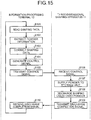
- FIG. 15 is a flowchart of an exemplary process performed by the three-dimensional shaping system according to an embodiment.
- the information processing terminal 12 reads the shaping data 510 of an intended three-dimensional shaped object (step S101) and extracts the powder information 521 corresponding to the powder 27 to be used (step S102). On the basis of the powder information 521, the information processing terminal 12 corrects the shaping data 510 so as to supplement the reduction amount of the layer 35 after the shaping liquid 55 is discharged (step S103).
- the information processing terminal 12 generates a control signal for controlling the supplying unit 502 and the discharging unit 503 on the basis of the shaping data 510 corrected at step S103 (step S104) and transmits the control signal to the shaping apparatus 11 (step S105).
- the shaping apparatus 11 When having received the control signal (step S106), the shaping apparatus 11 supplies the powder to the storage unit 501 on the basis of the control signal (step S107) and discharges the shaping liquid 55 onto the powder 27 provided in the storage unit 501 (step S108). Thereafter, the shaping apparatus 11 transmits a discharge completion signal indicating that the discharging of the shaping liquid 55 has been completed (step S109).
- the information processing terminal 12 Having received the discharge completion signal (step S110), the information processing terminal 12 reads the shaping data 510 again (step S101) and repeatedly performs the processes in the same manner to performs the shaping.
- FIG. 16 is a view for explaining how shaping is performed in actuality.
- the thickness of a first layer 35A of the powder 27 with which the previous layer was recoated is equal to 100 ⁇ m.
- the designed value t for the thickness of a layer of the powder 27 that is laminated in the recoating process at each time is assumed to be 100 ⁇ m.
- a second state 602 illustrates the situation after the shaping liquid 55 is discharged onto the first layer 35A of the powder 27.
- the thickness of a first permeation part 651A where the shaping liquid 55 has permeated in the first layer 35A is reduced (decreased). In the present example, the thickness is reduced from 100 ⁇ m to 66.7 ⁇ m. The reason is that the powder 27 sank due to a liquid bridge force of the shaping liquid 55 discharged onto the powder 27 and the gravity.
- the powder 27 aggregates also in the horizontal direction due to the liquid bridge force, so that a gap is formed as illustrated in FIG. 16 .
- FIG. 17 is a planar schematic view illustrating the situation where the gap is formed.
- FIG. 16 schematically illustrates the situation where the gap is formed in the left-and-right direction.
- the situation illustrated in FIG. 16 is rendered in a planar view, it is observed that the gap is formed randomly in the direction perpendicular to the Z-axis so that, as illustrated in FIG. 17 , the powder 27 aggregates in a reticulate formation (or with a patchy pattern).
- the first layer in this state is recoated with a second layer.
- a third state 603 illustrates the situation where the layer 35A in the second state 602 is recoated with a second layer 35B of the powder 27.
- the thickness reduction amount 33.3 ⁇ m in the first permeation part 651 A is also supplemented with the powder 27, so that the total thickness of the first layer 35A and the second layer 35B is equal to 200 ⁇ m.
- a fourth state 604 illustrates the situation after the shaping liquid 55 is discharged on the second layer 35B of the powder 27.
- the thickness of a second permeation part 651B where the shaping liquid 55 has permeated in the second layer 35B is reduced.
- the thickness is reduced from 133.3 ⁇ m to 88.9 ⁇ m.
- a fifth state 605 illustrates the situation where the layer 35B in the fourth state 604 is recoated with a third layer 35C of the powder 27.
- a reduction amount of 44.5 ⁇ m that is a total of the thickness reduction amount in the first permeation part 651A and the thickness reduction amount in the second permeation part 651B is supplemented, so that the total thickness of the first layer 35A, the second layer 35B, and the third layer 35C is equal to 300 ⁇ m.
- a sixth state 606 illustrates the situation after the shaping liquid 55 is discharged on the third layer 35C of the powder 27.
- the thickness of a third permeation part 651C where the shaping liquid 55 has permeated in the third layer 35C is reduced.
- the thickness is reduced from 144.5 ⁇ m to 96.3 ⁇ m.
- a seventh state 607 illustrates the situation where the previous layer is recoated with an n-th layer 35N of the powder 27.
- the reduction amount of 50 ⁇ m that is a total of the reduction amounts in the first to the (n-1)th permeation parts (651A, 651B, and so on) is supplemented, so that the total thickness of the first layer 35A to the n-th layer 35N is equal to (100 ⁇ n) ⁇ m.
- An eighth state 608 illustrates the situation after the shaping liquid 55 is discharged on the n-th layer 35N of the powder 27.
- the thickness of an n-th permeation part 651N where the shaping liquid 55 has permeated in the n-th layer 35N is reduced.
- the thickness is reduced from 150 ⁇ m to 100 ⁇ m.
- the thicknesses (66.7 ⁇ m, 88.9 ⁇ m, 96.3 ⁇ m,..., and 100 ⁇ m) of the plurality of permeation parts 651A to 651N that are in the laminated relationship increase as the number of laminated layers increases, so as to gradually become close to the designed value 100 ⁇ m for the thickness of the layer increased in the recoating processes.
- FIG. 18 is a chart illustrating a relationship between the thickness of a permeation part and the thickness increasing in actuality with respect to the number of laminated layers.
- FIG. 18 illustrates an example in which stainless steel powder is used as the powder 27.
- Used as the powder 27 was powder obtained by coating stainless steel powder (Gas-atomized powder PSS 316L, 20- ⁇ m grade, manufactured by Sanyo Special Steel Co., Ltd.) with a binder made of organic materials (acetoacetyl-group-modified polyvinyl alcohol: GOHSENX Z-100 manufactured by Nippon Synthetic Chemical Industry Co., Ltd.).
- stainless steel powder Gas-atomized powder PSS 316L, 20- ⁇ m grade, manufactured by Sanyo Special Steel Co., Ltd.
- a binder made of organic materials acetoacetyl-group-modified polyvinyl alcohol: GOHSENX Z-100 manufactured by Nippon Synthetic Chemical Industry Co., Ltd.
- binder made of organic materials
- the binder made of organic materials
- the shaping liquid 55 a liquid the main component of which is water and that contains any of the following that accounts for approximately 30% was used: an aqueous medium containing an alcohol such as ethanol, ether, ketone, and/or the like; aliphatic hydrocarbons; an ether-based solvent such as glycol ether; an ester-based solvent such as ethyl acetate; a ketone-based solvent such as methyl ethyl ketone; and a higher alcohol.
- an aqueous medium containing an alcohol such as ethanol, ether, ketone, and/or the like
- aliphatic hydrocarbons such as glycol ether
- an ester-based solvent such as ethyl acetate
- a ketone-based solvent such as methyl ethyl ketone
- FIG. 18 illustrates a relationship between the number of laminated layers and the thicknesses of the permeation parts 651A to 651N and a relationship between the number of laminated layers and the thicknesses of the layers 35A to 35N increasing in actuality in the recoating processes.
- the first asymptote 701 illustrates the relationship between the number of laminated layers and the thicknesses of the permeation parts 651A to 651N.
- the second asymptote 702 illustrates the relationship between the number of laminated layers and the thicknesses of the layers 35A to 35N increasing in actuality in the recoating processes.
- the thicknesses of the permeation parts 651A to 651N gradually become close to the designed value 100 ⁇ m for the thickness of the layer increasing in the recoating processes.
- the thicknesses of the permeation parts 651A to 651N become equal to approximately 100 ⁇ m when the number of laminated layers reaches five and hardly change thereafter.
- the thicknesses of the layers 35A to 35N increased in actuality in the recoating processes become equal to approximately 150 ⁇ m when the number of laminated layers reaches five and hardly change thereafter. Consequently, it is understood that, in the fifth layer and the layers thereafter, the shrinking effect of the layers caused by the sinking of the powder 27 due to the impacts of the liquid bridge force of the shaping liquid 55 discharged onto the powder 27 and the gravity becomes constant.
- t n denoting the thickness of each of the layers 35A to 35N (the permeation parts 651A to 651N) (the actual thickness of each single layer) after the shaping liquid is discharged on the n-th layer, using Expression (1) below.
- n is an integer selected from among 1, 2, 3,..., and m
- m denotes the total number of lamination levels (laminated layers).
- the reduction amount (the total reduction amount) of the thickness of the entire three-dimensional shaped object formed by the lamination is equal to the difference between mxt and t r .
- the method for adding the total reduction amount is not particularly limited.
- the total reduction amount may equally be divided (by the total number of laminated layers) and added to the designed value for the thickness of the three-dimensional shaped object in each of the layers.
- the total reduction amount may be distributed and added to the designed value for the thickness of the three-dimensional shaped object in each of the layers, so as to supplement reduction amounts that are different among the layers.
- FIG. 19 is a diagram for explaining an example of the powder information corresponding to the situation where stainless steel powder is used as the powder.
- the letter “m” denotes the total number of laminated layers and is equal to 10 in the present example.
- the letter “t” denotes the designed value for the thickness of the single layer (the thickness of each single layer) increased in the recoating processes and is equal to 100 ⁇ m in the present example.
- the letters “t i " denote the thickness (the actual thickness) after discharging the shaping liquid 55 on a layer having the thickness t and is equal to 66.6 ⁇ m in the present example.
- the letter “n” denotes the number of laminated layers.
- the letters “t n” denote an approximate value of the thickness of each of the permeation parts 651A to 651N in the laminated layers.
- the letters “t r " denotes the actual thickness of the entire three-dimensional shaped object and is the value calculated using Expression (2).
- the second term of t r denotes the value in the second term of Expression (2) for each of the layers.
- the first term of t r denotes the value in the first term of Expression (2) and is equal to 5,500 in the present example.
- the sum of the second terms of t r denotes the value of the sum of the second terms of Expression (2) and is equal to 4,074 in the present example.
- FIG. 20 is a first view for explaining a situation in which powder is provided prior to shaping the first layer.
- FIG. 21 is a second view for explaining the situation in which powder is provided prior to shaping the first layer.
- a first state 801 illustrates the situation in which the first layer 35A sufficiently thicker than the thickness tn of each single layer in the shaped object is laminated before dropping the shaping liquid 55 corresponding to the first layer.
- the first layer 35A is approximately 300 ⁇ m thick.
- the designed value t for the thickness of a layer of the powder 27 that is laminated in the recoating process at each time is assumed to be 100 ⁇ m.
- the quality of the shaped object is not stable because the powder particles easily move due to the liquid bridge force.
- a second state 802 illustrates the situation after the shaping liquid 55 is discharged on the first layer 35A of the powder 27 recoating the previous layer.
- the thickness of the first permeation part 651A where the shaping liquid 55 has permeated in the first layer 35A becomes slightly smaller than the original thickness of the first layer 35A due to the effect of the gravity, and also, the powder 27 aggregates also in the horizontal direction due to the liquid bridge force, so that a gap is formed as illustrated in FIG. 20 .
- a non-permeation part 651AA where the shaping liquid 55 has not permeated (the shaping liquid 55 has not spread).
- the movement of the powder particles in the lamination direction (the vertical direction) affected by the gravity is dominant.
- the first layer 35A of the shaped object in that state is subsequently recoated with the second layer 35B.
- the third state 803 indicates that the thickness of the second layer 35B of the powder 27 recoating the previous layer is equal to 100 ⁇ m.
- a fourth state 804 illustrates the situation after the shaping liquid 55 is discharged on the second layer 35B of the powder 27.
- the thickness of a second permeation part 651B where the shaping liquid 55 has permeated in the second layer 35B is reduced.
- the thickness is reduced from 100 ⁇ m to 66.7 ⁇ m.
- the second layer 35B of the shaped object in this state is subsequently recoated with a third layer 35C.
- the fifth state 805 also indicates that the thickness of the third layer 35C of the powder 27 recoating the previous layer is equal to 100 ⁇ m. With the recoating process at this time, the thickness reduction amount 33.3 ⁇ m in the second permeation part 651B is also supplemented with the powder 27, so that the total thickness of the second layer 35B and the third layer 35C is equal to 200 ⁇ m.
- a sixth state 806 illustrates the situation after the shaping liquid 55 is discharged on the third layer 35C of the powder 27.
- the thickness of a third permeation part 651C where the shaping liquid 55 has permeated in the third layer 35C is reduced.
- the thickness is reduced from 100 ⁇ m to 88.9 ⁇ m.
- the third layer 35C of the shaped object in this state is subsequently recoated with a fourth layer 35D.
- the seventh state 807 also indicates that the thickness of the fourth layer 35D of the powder 27 recoating the previous layer is equal to 100 ⁇ m. With the recoating process at this time, the thickness reduction amount 44.5 ⁇ m in the third permeation part 651C is also supplemented with the powder 27, so that the total thickness of the second layer 35B to the fourth layer 35D is equal to 300 ⁇ m.
- An eighth state 808 illustrates the situation after the shaping liquid 55 is discharged on the fourth layer 35D of the powder 27.
- the thickness of a fourth permeation part 651D where the shaping liquid 55 has permeated in the fourth layer 35D is reduced.
- the thickness is reduced from 100 ⁇ m to 96.3 ⁇ m.
- the fourth layer 35D of the shaped object in this state is subsequently recoated with a fifth layer 35E.
- the ninth state 809 also indicates that the thickness of the fifth layer 35E of the powder 27 recoating the previous layer is equal to 100 ⁇ m. With the recoating process at this time, the thickness reduction amount 48.1 ⁇ m in the fourth permeation part 651D is also supplemented with the powder 27, so that the total thickness of the second layer 35B to the fifth layer 35E is equal to 400 ⁇ m.
- a tenth state 810 illustrates the situation after the shaping liquid 55 is discharged on the fifth layer 35E of the powder 27.
- the thickness of a fifth permeation part 651E where the shaping liquid 55 has permeated in the fifth layer 35E is reduced.
- the thickness is reduced from 100 ⁇ m to 98.8 ⁇ m.
- the fifth layer 35E of the shaped object in this state is subsequently recoated with a sixth layer 35F.
- the eleventh state 811 also indicates that the thickness of the sixth layer 35F of the powder 27 recoating the previous layer is equal to 100 ⁇ m. With the recoating process at this time, the thickness reduction amount 49.8 ⁇ m in the fifth permeation part 651E is also supplemented with the powder 27, so that the total thickness of the second layer 35B to the sixth layer 35F is equal to 500 ⁇ m.
- a twelfth state 812 illustrates the situation after the shaping liquid 55 is discharged on the sixth layer 35F of the powder 27.
- the thickness of a sixth permeation part 651F where the shaping liquid 55 has permeated in the sixth layer 35F is reduced.
- the thickness is reduced from 100 ⁇ m to 99.6 ⁇ m.
- the sixth layer 35F of the shaped object in this state is subsequently recoated with a seventh layer 35G.
- the seventh layer 35G is a layer having a special role in the present embodiment.
- the seventh layer which exhibits that the thicknesses t n of the single layers in the shaped object have certainly become close to the designed value gradually, is provided as a separation layer onto which purposefully no shaping liquid 55 is dropped, as illustrated in FIG. 21 . Further, the shaped object up to the seventh layer is removed after the shaping, as a sacrificial layer serving as a sacrifice for obtaining a shaped object with desired precision.
- the thickness corresponding to the sacrificial layer is reflected into the data as a correction value for the design data, before the shaping is started.
- the thirteenth state 813 also indicates that the thickness of the seventh layer 35G of the powder 27 recoating the previous layer is equal to 100 ⁇ m.
- the thickness reduction amount 49.8 ⁇ m in the sixth permeation part 651F is also supplemented with the powder 27, so that the total thickness of the second layer 35B to the seventh layer 35G is equal to 600 ⁇ m.
- the seventh layer 35G of the shaped object in this state is subsequently recoated with an eighth layer 35H.
- the fourteenth state 814 also indicates that the thickness of the eighth layer 35H of the powder 27 recoating the previous layer is equal to 100 ⁇ m. With the recoating process at this time, the total thickness of the second layer 35B to the eighth layer 35H is equal to 700 ⁇ m.
- a fifteenth state 815 illustrates the situation after the shaping liquid 55 is discharged on the eighth layer 35H of the powder 27.
- the desired thickness of 100 ⁇ m is achieved.
- the shaping liquid 55 is discharged onto the eighth layer 35H, although no shaping liquid 55 has been dropped on the seventh layer 35G, because the moisture on the inside of the powder 27 has increased due to the shaping liquid 55 applied to the layer positioned underneath thereof (i.e., the sixth layer 35F), the movement of the particles in the horizontal direction is not as significant as in the first layer 3 5 A, and the sinking in the lamination direction is dominant.
- the thickness of the permeation part 651 G formed in the eighth layer 35H is substantially equal to the designed thickness t.
- FIG. 22 is a view for explaining a completed three-dimensional shaped object.
- a laminated member TD is formed in such a manner that a sacrifice member SA formed as a sacrificial layer and a three-dimensional shaped object MD are laminated together.
- the laminated member TD is separated into the sacrifice member SA and the three-dimensional shaped object MD by the seventh layer 35G formed as the separation layer, at the boundary between the sixth layer and the seventh layer.
- the design data should be corrected, in advance, with the amount corresponding to the thickness of the sacrificial layer to perform the shaping, and also, the shaping should be performed with a thickness set to be smaller by the amount corresponding to the single layer (100 ⁇ m in the present embodiment).
- the laminated member may be separated at the boundary between the seventh layer 35G and the permeation part 651G corresponding to the eighth layer 35H. In that situation, a correction should be made with the amount corresponding to the thickness of the sacrifice member SA serving as a sacrificial layer perform the shaping.
- FIG. 23 is a graph for explaining the situation in which zirconia powder is used as the powder.
- FIG. 23 illustrates a relationship between the number of laminated layers and the thicknesses of the permeation parts 651A to 651N and a relationship between the number of laminated layers and the thicknesses of the layers 35A to 35N increasing in actuality in the recoating processes.
- FIG. 24 is a diagram for explaining an example of the powder information corresponding to the situation where zirconia powder is used as the powder.
- the thicknesses of the permeation parts 651A to 651N gradually become close to the designed value 100 ⁇ m for the thickness of the layer increasing in the recoating processes, as the number of laminated layers increases.
- the thicknesses of the permeation parts 651A to 651N become substantially equal to 100 ⁇ m when the number of laminated layers has reached 12. Consequently, it is understood that, when the zirconia powder is used, the impact of the shrinkage of the powder 27 is constant in the twelfth layer and the layers thereafter.
- the pieces of powder information 521A and 521B illustrated in FIGS. 19 and 24 are merely examples, and possible embodiments of the powder information 521 are not limited to these examples.
- the powder information 521 may be generated for each combination of the powder 27 (including various conditions such as the type of powder, the method for generating particles, the diameter of the powder particles, the diameter of the generated particles, and the like) and the shaping liquid 55. This arrangement is effective when a plurality of types of shaping liquid 55 is used with one type of powder 27.
- the powder information 521 may be generated in association with environment information such as temperature, humidity, and the like. This arrangement is effective when the fluctuation of the shrinking ratio k (the density) of the powder 27 significantly changes depending on the environment.
- the sacrificial layer having the intended thickness by finding out, in advance, the shrinking ratio of the powder particles structuring the powder and incorporating the shrinking ratio into a program or the like.
- the present embodiment it is possible to prevent harmful effects such as degradation of precision in shaping (planarity or flatness being degraded) caused by the shrinkage of the layers 35 caused by the permeation of the shaping liquid 55, and it is also possible to obtain a shaped object with high precision in shaping while keeping minimum shaping materials to be wasted and shaping time periods to be wasted.
- the thickness of the sacrificial layer is arranged to be equal to the thickness of the layers of the three-dimensional shaped object; however, it is possible to achieve the same advantageous effects by arranging the thickness of each of the layers laminated in the sacrificial layer to be thinner and performing the laminating processes until the thickness per layer becomes equal to a predetermined thickness. Further, with this arrangement, it is possible to suppress the amounts of powder and shaping liquid to be consumed for forming the sacrificial layer.
- any of the above-described apparatus, devices or units can be implemented as a hardware apparatus, such as a special-purpose circuit or device, or as a hardware/software combination, such as a processor executing a software program.
- any one of the above-described and other methods of the present invention may be embodied in the form of a computer program stored in any kind of storage medium.
- storage mediums include, but are not limited to, flexible disk, hard disk, optical discs, magneto-optical discs, magnetic tapes, nonvolatile memory, semiconductor memory, read-only-memory (ROM), etc.
- any one of the above-described and other methods of the present invention may be implemented by an application specific integrated circuit (ASIC), a digital signal processor (DSP) or a field programmable gate array (FPGA), prepared by interconnecting an appropriate network of conventional component circuits or by a combination thereof with one or more conventional general purpose microprocessors or signal processors programmed accordingly.
- ASIC application specific integrated circuit
- DSP digital signal processor
- FPGA field programmable gate array
- Processing circuitry includes a programmed processor, as a processor includes circuitry.
- a processing circuit also includes devices such as an application specific integrated circuit (ASIC), digital signal processor (DSP), field programmable gate array (FPGA) and conventional circuit components arranged to perform the recited functions.
- ASIC application specific integrated circuit
- DSP digital signal processor
- FPGA field programmable gate array
Landscapes
- Chemical & Material Sciences (AREA)
- Engineering & Computer Science (AREA)
- Materials Engineering (AREA)
- Manufacturing & Machinery (AREA)
- Physics & Mathematics (AREA)
- Mechanical Engineering (AREA)
- Optics & Photonics (AREA)
- Producing Shaped Articles From Materials (AREA)
- Powder Metallurgy (AREA)
Abstract
Description
- The present invention relates to a three-dimensional shaping apparatus, a method for controlling a three-dimensional shaping apparatus, and a program.
- As a method for manufacturing a three-dimensional shaped object, a powder lamination shaping method of a binder-jet type is known. According to this shaping method, a step of supplying material powder to the inside of a container in a predetermined amount at a time so as to form a powder layer and a step of discharging shaping liquid that solidifies the powder onto the powder so as to solidify a predetermined part thereof are repeatedly performed to manufacture the intended three-dimensional shaped object in the container.
- For example, a disclosed apparatus is configured to form a base layer of a overhung part in a (k+1)th layer during a bonding step of a k-th layer, for the purpose of preventing bonding liquid (shaping liquid) from permeating into a lower layer when the overhung part is formed (Japanese Patent No.
5,471,939 - According to the powder lamination shaping method of the binder-jet type, when the shaping liquid permeates into the powder, the density of the powder is increased by the liquid bridge force of the shaping liquid, so that the thickness of the powder layer is reduced. However, because the shrinking direction is random, an error may occur in the length or the shape of the intended three-dimensional shaped object, also in locations other than the overhung part such as, for example, the bottom face of the shaped object.
- In view of the circumstances described above, it is an object of the present invention to improve the precision in shaping the three-dimensional shaped object.
- According to one aspect of the present invention, a three-dimensional shaping apparatus includes a storage unit, a supplying unit, a discharging unit, and a controlling unit. The storage unit is configured to store powder. The supplying unit is configured to supply the powder to the storage unit to form a layer of the powder. The discharging unit is configured to discharge shaping liquid to solidify the powder onto the powder. The controlling unit is configured to generate a control signal for controlling the supplying unit and the discharging unit based on shaping data indicating a shape of a three-dimensional shaped object. The controlling unit is configured to generate the control signal for laminating at least one sacrificial layer separable from at least one shaping layer corresponding to the three-dimensional shaped object in such a position that the at least one sacrificial layer is under the at least one shaping layer, prior to laminating the at least one shaping layer, based on the shaping data and powder information stored in advance and indicating change in thickness of a layer of the powder caused by permeation of the shaping liquid.
- According to one aspect of the present invention, it is possible to improve the precision in shaping the three-dimensional shaped object.
-
-
FIG. 1 is a diagram for explaining an overview of an exemplary hardware configuration of a three-dimensional shaping system according to an embodiment; -
FIG. 2 is a top view of an exemplary hardware configuration of a shaping apparatus according to a first aspect; -
FIG. 3 is an exemplary lateral view of a part of the hardware configuration of the shaping apparatus according to the first aspect; -
FIG. 4 is an exemplary perspective view of a part of the hardware configuration of the shaping apparatus according to the first aspect; -
FIG. 5 is a view for explaining an exemplary operational state of the shaping apparatus according to the first aspect; -
FIG. 6 is a diagram for explaining an exemplary internal hardware configuration of the shaping apparatus according to the first aspect; -
FIG. 7 is a view for explaining a manner in which shaping liquid is being discharged onto a powder layer by the shaping apparatus according to the first aspect; -
FIG. 8 is a view for explaining a state in which a shaping layer has been formed by the shaping apparatus according to the first aspect; -
FIG. 9 is a view for explaining a manner in which a new batch of powder is being supplied onto a layer containing a shaping layer, by the shaping apparatus according to the first aspect; -
FIG. 10 is a view for explaining a state in which a previous layer has been recoated with a new powder layer by the shaping apparatus according to the first aspect; -
FIG. 11 is a view for explaining an example of a state of powder on which shaping liquid has been discharged by the shaping apparatus according to the first aspect; -
FIG. 12 is a perspective view for explaining a part of a hardware configuration of a shaping apparatus according to a second aspect; -
FIG. 13 is an overview diagram of hardware of an information processing terminal according to an embodiment; -
FIG. 14 is a functional configuration block diagram of a three-dimensional shaping system according to an embodiment; -
FIG. 15 is a flowchart of an exemplary process performed by the three-dimensional shaping system according to an embodiment; -
FIG. 16 is a view for explaining how shaping is performed in actuality; -
FIG. 17 is a planar schematic view illustrating a situation where a gap is formed; -
FIG. 18 is a chart illustrating a relationship between the thickness of a permeation part and the thickness increasing in actuality with respect to the number of laminated layers; -
FIG. 19 is a diagram for explaining an example of powder information corresponding to a situation where stainless steel powder is used as the powder; -
FIG. 20 is a first view for explaining a situation in which powder is provided prior to shaping the first layer; -
FIG. 21 is a second view for explaining the situation in which powder is provided prior to shaping the first layer; -
FIG. 22 is a view for explaining a completed three-dimensional shaped object; -
FIG. 23 is a graph for explaining a situation in which zirconia powder is used as the powder; and -
FIG. 24 is a diagram for explaining an example of the powder information corresponding to a situation where zirconia powder is used as the powder. - The accompanying drawings are intended to depict exemplary embodiments of the present invention and should not be interpreted to limit the scope thereof. Identical or similar reference numerals designate identical or similar components throughout the various drawings.
- The terminology used herein is for the purpose of describing particular embodiments only and is not intended to be limiting of the present invention.
- As used herein, the singular forms "a", "an" and "the" are intended to include the plural forms as well, unless the context clearly indicates otherwise.
- In describing preferred embodiments illustrated in the drawings, specific terminology may be employed for the sake of clarity. However, the disclosure of this patent specification is not intended to be limited to the specific terminology so selected, and it is to be understood that each specific element includes all technical equivalents that have the same function, operate in a similar manner, and achieve a similar result.
- An embodiment of the present invention will be described in detail below with reference to the drawings.
-
FIG. 1 is a diagram for explaining an overview of an exemplary hardware configuration of a three-dimensional shaping system according to an embodiment. - A three-
dimensional shaping system 1 includes a three-dimensional shaping apparatus (hereinafter, simply "shaping apparatus") 11, aninformation processing terminal 12, and anetwork 13. - The
shaping apparatus 11 is an apparatus configured to form a three-dimensional shaped object having an arbitrary shape by a powder lamination shaping method of a binder-jet type to. In the powder lamination shaping method of the binder-jet type, a step of supplying material powder to the inside of a container in a predetermined amount at a time so as to form a powder layer and a step of discharging shaping liquid that solidifies the powder onto the powder so as to solidify a predetermined part thereof are repeatedly performed to manufacture the intended three-dimensional shaped object in the container. - The
information processing terminal 12 is an apparatus configured to generate a control signal for controlling theshaping apparatus 11. Theinformation processing terminal 12 may be, for example, a general-purpose computer, a tablet, a smartphone, or the like provided with a Micro Processing Unit (MPU), a Read-Only Memory (ROM), a Random Access Memory (RAM), and an external storage device configured with a semiconductor memory device or the like. However, possible embodiments of theinformation processing terminal 12 are not limited to these examples. - The
network 13 is a computer network that is either well-known or novel and makes it possible for theshaping apparatus 11 and theinformation processing terminal 12 to transmit and receive signals to and from each other, while ensuring a communication speed required for controlling processes. - Although
FIG. 1 illustrates the example in which thesingle shaping apparatus 11 and the singleinformation processing terminal 12 are connected to each other via thenetwork 13, two or moreshaping apparatuses 11 and/or two or moreinformation processing terminals 12 may be provided. -
FIG. 2 is a top view of an exemplary hardware configuration of a shaping apparatus according to a first aspect. -
FIG. 3 is an exemplary lateral view of a part of the hardware configuration of the shaping apparatus according to the first aspect. -
FIG. 4 is an exemplary perspective view of a part of the hardware configuration of the shaping apparatus according to the first aspect. -
FIG. 5 is a view for explaining an exemplary operational state of the shaping apparatus according to the first aspect. - The shaping
apparatus 11 includes astorage unit 21, a supplyingunit 22, a shapingliquid reservoir unit 23, a dischargingunit 24, and amaintenance unit 25. - The
storage unit 21 is a unit configured to store thereinpowder 27 for forming the three-dimensional shaped object. Thestorage unit 21 includes a shapingchamber 31, a shapingstage 32, and aroller 33. - The shaping
chamber 31 is a member configured to store therein thepowder 27 supplied thereto from the supplying unit 22 (explained later) and to have the three-dimensional shaped object formed in the inside thereof. - The shaping
stage 32 is a member positioned at the bottom of the shapingchamber 31 and is configured to move in the Z-direction. The volume of the shapingchamber 31 changes as a result of raising and lowering the shapingstage 32. The shapingstage 32 is lowered as the number of layers of thepowder 27 increases. - The
roller 33 is a member configured to flatten the surface of thepowder 27 supplied from the supplyingunit 22 to the inside of the shapingchamber 31. Theroller 33 is configured to move in the X-direction and also to rotate. - The supplying
unit 22 is a unit configured to supply thepowder 27 to the storage unit 21 (the shaping chamber 31) and includes a storing container 47 and ashutter 42. - The storing
container 41 is a container configured to store thepowder 27 therein. Anopening 43 is formed in a lower end part of the storingcontainer 41. The storingcontainer 41 is fixed to acarriage 61 of the discharging unit 24 (explained later) and is configured to move together with thecarriage 61. - The
shutter 42 is a member configured to open and close theopening 43 of the storingcontainer 41. The amount of thepowder 27 supplied to the shapingchamber 31 is adjusted according to the time period during which theshutter 42 is open. - The shaping
liquid reservoir unit 23 is a unit configured to store therein shapingliquid 55 that solidifies thepowder 27. The shapingliquid reservoir unit 23 includes atank attaching member 51 andtanks 52. - The
tank attaching member 51 is a member configured to detachably fix thetanks 52. - The
tanks 52 are each a member configured to store the shapingliquid 55 on the inside thereof. In the present example, the plurality oftanks 52 are installed, and mutually-different types of shapingliquid 55 may be stored in thetanks 52. Examples of the shaping liquid include a liquid the main component of which is water and that contains any of the following: an aqueous medium containing alcohol, ether, ketone, and/or the like; aliphatic hydrocarbons; an ether-based solvent such as glycol ether; an ester-based solvent such as ethyl acetate; a ketone-based solvent such as methyl ethyl ketone; and a higher alcohol; however, possible embodiments are not limited to these examples. The inside of each of thetanks 52 is in communication with dischargingheads 62 of the discharging unit 24 (explained later) via passages (not illustrated). - The discharging
unit 24 is a unit configured to discharge the shapingliquid 55 onto thepowder 27 provided in the storage unit 21 (the shaping chamber 31). The dischargingunit 24 includes thecarriage 61 and the dischargingheads 62. - The
carriage 61 is a member configured to fix the supplyingunit 22 and the dischargingheads 62. Thecarriage 61 is linked tofirst rails 71 installed in parallel to the X-direction and is configured to move (to change the position thereof) along the first rails 71 (in the X-direction). The two ends of each of thefirst rails 71 are fixed tolateral plates 72. Thelateral plates 72 are fixed tosliders 73. Thesliders 73 are linked tosecond rails 74 installed in parallel to the Y-direction and are configured to move (to change the position thereof) along the second rails 74 (in the Y-direction). The second rails 74 are configured to move in the Z-direction. In this structure, thecarriage 61 is capable of moving in a three-dimensional manner. As thecarriage 61 moves, the supplyingunit 22 and the dischargingheads 62 fixed to thecarriage 61 also move. - The discharging heads 62 are each a member configured to discharge the shaping
liquid 55 stored in thetanks 52 toward thepowder 27 provided in the shapingchamber 31. The discharging heads 62 each including a plurality ofnozzles 64 directed downward. The discharging heads 62 and thetanks 52 are in communication with each other via passages (not illustrated). In the present example, two dischargingheads 62 are provided. The discharging heads 62 may discharge mutually-different types of shapingliquid 55. - The
maintenance unit 25 is a unit configured to perform maintenance on the dischargingunit 24 and includescaps 81 and awiper 82. - The
caps 81 are configured to adhere closely to the surfaces of the dischargingheads 62 where thenozzles 64 are formed and to suck the shapingliquid 55 out of thenozzles 64. As a result, it is possible to remove thepowder 27 clogging thenozzles 64 and the shapingliquid 55 that has become highly concentrated. Further, by covering thenozzles 64 with thecaps 81 when the shapingliquid 55 is not being discharged, it is possible to prevent thepowder 27 from erroneously entering thenozzles 64 and to prevent the shapingliquid 55 from getting dry. - The
wiper 82 is a member configured to wipe the surfaces of the dischargingheads 62 where thenozzles 64 are formed. - The
storage unit 21, the supplyingunit 22, the shapingliquid reservoir unit 23, the dischargingunit 24, and themaintenance unit 25 are controlled on the basis of the control signal provided from theinformation processing terminal 12. For example, the supplying of thepowder 27 to the shapingchamber 31, the moving of thecarriage 61, the discharging of the shapingliquid 55, the selection of the type of the shapingliquid 55 to be discharged, the execution of the maintenance, and the like are controlled on the basis of the control signal. As a result of an operation of the shapingapparatus 11, as illustrated inFIG. 5 , alayer 35 or thepowder 27 is formed in an upper layer part of the shapingchamber 31. As a result of discharging the shapingliquid 55 onto thelayer 35, ashaping layer 36 obtained by solidifying thepowder 27 is formed. As a result of laminating together shapinglayers 36 ofmultiple layers 35, the intended three-dimensional shaped object is formed. -
FIG. 6 is a diagram for explaining an exemplary internal hardware configuration of the shaping apparatus according to the first aspect. - A controlling
unit 100 of the shapingapparatus 11 includes amain controlling unit 100A. Themain controlling unit 100A includes: a Central Processing Unit (CPU) 101 configured to exercise overall control of the shapingapparatus 11; a Read-Only Memory (ROM) 102 configured to store therein a program that controls theCPU 101 and other fixed data; and a Random Access Memory (RAM) 103 configured to temporarily store therein the control signal and the like. - The controlling
unit 100 includes a non-volatile memory (Non-Volatile RAM [NVRAM]) 104, an Application Specific Integrated Circuit (ASIC) 105, an external interface (I/F) 106, and an Input/Output (I/O)unit 107. - The
NVRAM 104 is a memory for holding data even while the power source of the apparatus is shut down. TheASIC 105 is configured to perform an image processing process on three-dimensional shaping data and other processing processes such as a processing process on input/output signals for controlling the entirety of the apparatus. The external I/F 106 is configured to receive the control signal output from theinformation processing terminal 12. The I/O unit 107 is configured to obtain an input of a detection signal from any of various types of sensors including a temperature/humidity sensor 122. - The controlling
unit 100 includes a headdrive controlling unit 108 configured to control driving of the dischargingheads 62. - The controlling
unit 100 includes amotor driving unit 110 configured to drive anX-direction scanning mechanism 131 that causes thecarriage 61 to move in the X-direction, amotor driving unit 111 configured to drive a Y-direction scanning mechanism 132 that causes thecarriage 61 to move in the Y-direction, and amotor driving unit 112 configured to drive a Z-direction scanning mechanism 133 that causes thecarriage 61 to move in the Z-direction. - Further, the controlling
unit 100 includes amotor driving unit 114 configured to drive amotor 134 that raises and lowers the shapingstage 32, amotor driving unit 115 configured to drive amotor 135 that causes theroller 33 to reciprocate along the X-direction, and amotor driving unit 116 configured to drive amotor 136 that causes theroller 33 to rotate. - Further, the controlling
unit 100 includes a maintenance driving unit 117 configured to drive themaintenance unit 25 and asupply driving unit 118 configured to drive the supplying unit 22 (the shutter 42). - The I/
O unit 107 is configured to receive an input of a detection signal from the temperature/humidity sensor 122 or the like, the temperature/humidity sensor 122 being configured to detect temperature and humidity levels representing environment conditions. The controllingunit 100 has connected thereto anoperation panel 121 for inputting necessary information to theshaping apparatus 11 and displaying information is connected to the controllingunit 100. -
FIGS. 7 to 10 illustrate a procedure for forming the three-dimensional shaped object. -
FIG. 7 is a view for explaining a manner in which shaping liquid is being discharged onto a powder layer by the shaping apparatus according to the first aspect. -
FIG. 8 is a view for explaining a state in which a shaping layer has been formed by the shaping apparatus according to the first aspect. -
FIG. 8 illustrates the state in which theshaping layer 36 has been formed as a result of solidifying the part onto which the shapingliquid 55 was discharged. -
FIG. 9 is a view for explaining a manner in which a new batch of powder is being supplied onto a layer containing a shaping layer, by the shaping apparatus according to the first aspect. -
FIG. 9 illustrates the manner in which thepowder 27 stored in the supplyingunit 22 is being supplied to the inside of the shapingchamber 31. In this situation, the shapingstage 32 is lowered in the direction indicated by the arrow Z1, so that the length from the top face of thelayer 35 containing theshaping layer 36 to the upper end of the shapingchamber 31 becomes equal to t. In this situation t denotes the thickness of thesingle layer 35. Thereafter, the supplyingunit 22 moves toward the right side of the drawing while dropping thepowder 27. Theroller 33 moves across the top face of the shapingchamber 31 toward the right side of the drawing, while rotating to flatten the top surface of thepowder 27 provided within the area of the shapingstage 32, while being in contact with the upper end of the shapingstage 32. As a result, a state is achieved where thepowder 27 is supplied up to the upper end of the shapingstage 32. -
FIG. 10 is a view for explaining a state in which the previous layer has been recoated with a new powder layer by the shaping apparatus according to the first aspect. -
FIG. 10 illustrates the state in which the layers containing theshaping layer 36 are recoated with anew layer 35, as a result of theroller 33 moving across the top face of the shapingchamber 31 up to the right end of the drawing. -
FIG. 11 is a view for explaining an example of a state of the powder on which the shaping liquid has been discharged by the shaping apparatus according to the first aspect. - The example in
FIG. 11 illustrates a permeation state when generating two-dimensional image data with a pitch of 300 x 300 dpi (corresponding to approximately 85 µm) and discharging adroplet 29 of the shapingliquid 55 so that thedroplet 29 lands on thepowder 27 on the basis of the generated data. It is desirable that the amount of liquid in thesingle droplet 29 is exactly as much as necessary to permeate the thickness t (e.g., 100 µm) of thesingle layer 35. It is possible to empirically learn the amount of liquid in thedroplet 29. For example, thedroplet 29 may be dropped onto thepowder 27 spread to fill the area of a glass substrate with a thickness of 100 µm. In that situation, using a camera to observe the surface opposite from the surface on which the droplet was dropped, it is possible to judge whether or not the shapingliquid 55 corresponding to thedroplet 29 has permeated the thickness of 100 µm. By repeatedly performing such an experiment while varying the amount of liquid in thedroplet 29, it is possible to find out the amount of liquid in thedroplet 29 required to exactly permeate the thickness of 100 µm. -
FIG. 12 is a perspective view for explaining a part of a hardware configuration of a shaping apparatus according to a second aspect. - The second aspect illustrated in
FIG. 12 is different from the first aspect illustrated inFIGS. 2 to 5 for the mechanism in supplying thepowder 27 to a shapingchamber 93. The configuration according to the second aspect includes a storing/supplyingunit 91. - The storing/supplying
unit 91 includes a supplyingchamber 92, the shapingchamber 93, asurplus receiving chamber 94, a supplyingstage 95, a shapingstage 96, and aroller 97. - The supplying
chamber 92 is a member configured to store therein thepowder 27 to be transported to the shapingchamber 93. - The shaping
chamber 93 is a member configured to store therein thepowder 27 transported thereto from the supplyingchamber 92 and to have a three-dimensional shaped object formed in the inside thereof. - The
surplus receiving chamber 94 is a member configured to receivesurplus powder 27 spilling from the supplyingchamber 92 and the shapingchamber 93. - The supplying
stage 95 is installed at the bottom of the supplyingchamber 92 and is configured to move in parallel to the Z-direction. The supplyingstage 95 is raised when thepowder 27 is supplied, so as to push up thepowder 27 above the upper end of the supplyingchamber 92. - The shaping
stage 96 is installed at the bottom of the shapingchamber 93 and is configured to move in parallel to the Z-direction. The shapingstage 96 is lowered when thepowder 27 is supplied, so as to ensure that thepowder 27 transported thereto from the supplyingchamber 92 is received into the shapingchamber 93. - The
roller 97 is a member configured to reciprocate along the Y-direction and also to rotate. Theroller 97 is configured to move along the Y-direction when thepowder 27 is supplied and to transport thepowder 27 raised above the supplyingchamber 92 to the shapingchamber 93. In that situation, as a result of theroller 97 rotating, the surface of thepowder 27 provided in the shapingchamber 93 is flattened. - It is possible to adjust the amount of the
powder 27 supplied to the shapingchamber 93 by adjusting, for example, how much the supplyingstage 95 is raised and how much the shapingstage 96 is lowered. - By using the configuration according to the second aspect, it is also possible to form a three-dimensional shaped object in the same manner as in the first aspect illustrated in
FIGS. 2 to 5 . -
FIG. 13 is an overview diagram of hardware of an information processing terminal according to an embodiment. - The
information processing terminal 12 includes aCPU 201, aROM 202, aRAM 203, aninput device 204, anoutput device 205, a communication interface (I/F) 206, and abus 207. TheCPU 201 is configured to perform a predetermined arithmetic process according to a control program stored in theROM 202 while using theRAM 203 as a working area. Theinput device 204 is a device for receiving an input of information from the outside thereof and may be configured with, for example, a keyboard, a mouse, a touch panel and/or the like. Theoutput device 205 is a device for outputting information generated on the inside to the outside and may be configured with a display device, for example. The communication I/F 206 is a device that makes it possible to transmit and receive signals to and from the shapingapparatus 11 or the like via thenetwork 13. -
FIG. 14 is a functional configuration block diagram of a three-dimensional shaping system according to an embodiment. - The shaping
apparatus 11 includes astorage unit 501, a supplyingunit 502, and a dischargingunit 503. Theinformation processing terminal 12 includes agenerating unit 511, a correctingunit 512, and amemory unit 513. - The
storage unit 501 is configured to store therein the suppliedpowder 27 and to have a three-dimensional shaped object formed in the inside thereof. Thestorage unit 501 may be realized using, for example, the shapingchamber 31 according to the first aspect illustrated inFIGS. 2 to 5 or the shapingchamber 93 according to the second aspect illustrated inFIG. 12 ; however, possible embodiments are not limited to these examples. - The supplying
unit 502 is configured to supply thepowder 27 to thestorage unit 501 in accordance with the control signal from theinformation processing terminal 12. The supplyingunit 502 may be realized using, for example, the supplyingunit 22 according to the first aspect or the supplyingchamber 92, the supplyingstage 95, and theroller 97 according to the second aspect, or the like; however, possible embodiments are not limited to these examples. - The discharging
unit 503 is configured to discharge the shapingliquid 55 onto thepowder 27 provided in thestorage unit 501 in accordance with the control signal output from theinformation processing terminal 12. The dischargingunit 503 may be realized using, for example, the shapingliquid reservoir unit 23 and the dischargingunit 24 according to the first aspect, or the like; however, possible embodiments are not limited to these examples. - The generating
unit 511 is configured to generate the control signal for controlling the supplyingunit 502 and the dischargingunit 503. The control signal is generated on the basis of shapingdata 510 stored in thememory unit 513. The shapingdata 510 is information indicating the shape of the intended three-dimensional shaped object and includes a designed thickness (the length of the mass of thepowder 27 in the lamination direction) of the three-dimensional shaped object. The shapingdata 510 may be data for a three-dimensional Computer-Aided Design system (3D-CAD) or the like in, for example, a Standard Triangulated Language (STL) format or a Virtual Reality Modeling Language (VRML) format. The shapingdata 510 may be generated from, for example, a two-dimensional design diagram or three-dimensional scan data of the three-dimensional shaped object. The method for obtaining the shapingdata 510 shall not particularly be limited. The shapingdata 510 may be obtained, for example, through an input operation performed by a user, an input from another device, or information read from a storage medium or the like. The generatingunit 511 may be realized by a collaboration or the like of theCPU 201, the control program stored in theROM 202, theRAM 203 functioning as a working area, an appropriate logic Integrated Circuit (IC), and the like; however, possible embodiments are not limited to these examples. - The correcting
unit 512 is configured to correct the shapingdata 510 on the basis ofpowder information 521 stored in thememory unit 513. Thepowder information 521 is information indicating changes in the thickness of thelayer 35 of thepowder 27 caused by permeation of the shapingliquid 55. It is desirable to generate a plurality of pieces ofpowder information 521 in correspondence with different types ofpowder 27. On the basis of thepowder information 521, the correctingunit 512 is configured to correct the shapingdata 510 so as to supplement a reduction amount in the thickness of thelayer 35 after the shapingliquid 55 is discharged. For example, the correctingunit 512 corrects the shapingdata 510 so as to increase the designed thickness of the intended three-dimensional shaped object. The correctingunit 512 may be realized by a collaboration or the like of theCPU 201, the control program stored in theROM 202, theRAM 203 functioning as a working area, an appropriate logic Integrated Circuit (IC), and the like; however, possible embodiments are not limited to these examples. - The
memory unit 513 is configured to store therein the shapingdata 510, thepowder information 521, and other appropriate pieces of information. Thememory unit 513 may be realized using theROM 202, theRAM 203 functioning as a temporary storage area, and the like; however, possible embodiments are not limited to these examples. AlthoughFIG. 14 illustrates an example in which thepowder information 521 is held inside theinformation processing terminal 12, thepowder information 521 may be held in a storage device provided on the outside of theinformation processing terminal 12. - The control program configured to realize functions of the
generating unit 511 and the correcting unit 512 (including the function of either obtaining or generating the shaping data 510) may be provided as being recorded on a computer-readable recording medium such as a Compact Disk Read-Only Memory (CD-ROM), a Flexible Disk (FD), a Compact Disk Recordable (CD-R), or a Digital Versatile Disk (DVD), in a file in an installable format or an executable format. - The control program may be configured so as to be provided as being stored in a computer (a server) connected to the
network 13 such as the Internet and being downloaded via thenetwork 13. The control program may be configured so as to be provided or distributed via thenetwork 13. Alternatively, the control program may be configured so as to be provided as being incorporated in theROM 202 or the like in advance. - The control program may be configured as a module including the functional units (the generating
unit 511 and the correcting unit 512) described above. In that situation, as a result of theCPU 201 reading and executing the control program from theROM 202, the functional units are generated in theRAM 203. -
FIG. 15 is a flowchart of an exemplary process performed by the three-dimensional shaping system according to an embodiment. - The
information processing terminal 12 reads the shapingdata 510 of an intended three-dimensional shaped object (step S101) and extracts thepowder information 521 corresponding to thepowder 27 to be used (step S102). On the basis of thepowder information 521, theinformation processing terminal 12 corrects the shapingdata 510 so as to supplement the reduction amount of thelayer 35 after the shapingliquid 55 is discharged (step S103). - The
information processing terminal 12 generates a control signal for controlling the supplyingunit 502 and the dischargingunit 503 on the basis of the shapingdata 510 corrected at step S103 (step S104) and transmits the control signal to the shaping apparatus 11 (step S105). - When having received the control signal (step S106), the shaping
apparatus 11 supplies the powder to thestorage unit 501 on the basis of the control signal (step S107) and discharges the shapingliquid 55 onto thepowder 27 provided in the storage unit 501 (step S108). Thereafter, the shapingapparatus 11 transmits a discharge completion signal indicating that the discharging of the shapingliquid 55 has been completed (step S109). - Having received the discharge completion signal (step S110), the
information processing terminal 12 reads the shapingdata 510 again (step S101) and repeatedly performs the processes in the same manner to performs the shaping. - Next, a principle of the exemplary embodiments will be explained before providing a detailed description of the embodiments.
- It would be ideal if the thickness of the shaped object was equal to the predetermined thickness (t=100 µm) as a result of the shaping
liquid 55 being dropped onto thepowder 27 provided in thestorage unit 501. Further, by repeatedly performing such shaping is repeatedly performed ten times to form a shaped object having a thickness of 1000 µm, for example However, the shaping in actuality does not work in this manner generally. - In the following sections, how shaping is performed in actuality will be explained.
-
FIG. 16 is a view for explaining how shaping is performed in actuality. - In a
first state 601, the thickness of afirst layer 35A of thepowder 27 with which the previous layer was recoated is equal to 100 µm. Similarly, in the example inFIG. 16 , the designed value t for the thickness of a layer of thepowder 27 that is laminated in the recoating process at each time is assumed to be 100 µm. - A
second state 602 illustrates the situation after the shapingliquid 55 is discharged onto thefirst layer 35A of thepowder 27. The thickness of afirst permeation part 651A where the shapingliquid 55 has permeated in thefirst layer 35A is reduced (decreased). In the present example, the thickness is reduced from 100 µm to 66.7 µm. The reason is that thepowder 27 sank due to a liquid bridge force of the shapingliquid 55 discharged onto thepowder 27 and the gravity. - In that situation, because no shaping
liquid 55 at all is applied to thepowder 27 in the first layer, the friction among the powder particles is relatively small, and thepowder 27 is therefore in a free state. - Accordingly, when the shaping
liquid 55 is dropped onto thepowder 27 in the free state, thepowder 27 aggregates also in the horizontal direction due to the liquid bridge force, so that a gap is formed as illustrated inFIG. 16 . -
FIG. 17 is a planar schematic view illustrating the situation where the gap is formed. -
FIG. 16 schematically illustrates the situation where the gap is formed in the left-and-right direction. In contrast, when the situation illustrated inFIG. 16 is rendered in a planar view, it is observed that the gap is formed randomly in the direction perpendicular to the Z-axis so that, as illustrated inFIG. 17 , thepowder 27 aggregates in a reticulate formation (or with a patchy pattern). - Subsequently, the first layer in this state is recoated with a second layer.
- In other words, a
third state 603 illustrates the situation where thelayer 35A in thesecond state 602 is recoated with asecond layer 35B of thepowder 27. With the recoating process at this time, the thickness reduction amount 33.3 µm in thefirst permeation part 651 A is also supplemented with thepowder 27, so that the total thickness of thefirst layer 35A and thesecond layer 35B is equal to 200 µm. - In this situation, as for the
powder 27 in the second layer and the layers thereafter, because the friction against the movement of the powder particles in the horizontal direction increases due to an impact from the shapingliquid 55 in the layer positioned underneath (e.g., the first layer for the second layer), the movement of the powder particles in the lamination direction (the vertical direction) affected by the gravity is dominant. - A
fourth state 604 illustrates the situation after the shapingliquid 55 is discharged on thesecond layer 35B of thepowder 27. The thickness of asecond permeation part 651B where the shapingliquid 55 has permeated in thesecond layer 35B is reduced. In the present example, the thickness is reduced from 133.3 µm to 88.9 µm. - A
fifth state 605 illustrates the situation where thelayer 35B in thefourth state 604 is recoated with athird layer 35C of thepowder 27. With the recoating process at this time, a reduction amount of 44.5 µm that is a total of the thickness reduction amount in thefirst permeation part 651A and the thickness reduction amount in thesecond permeation part 651B is supplemented, so that the total thickness of thefirst layer 35A, thesecond layer 35B, and thethird layer 35C is equal to 300 µm. - A
sixth state 606 illustrates the situation after the shapingliquid 55 is discharged on thethird layer 35C of thepowder 27. The thickness of athird permeation part 651C where the shapingliquid 55 has permeated in thethird layer 35C is reduced. In the present example, the thickness is reduced from 144.5 µm to 96.3 µm. - A
seventh state 607 illustrates the situation where the previous layer is recoated with an n-th layer 35N of thepowder 27. With the recoating process at this time, the reduction amount of 50 µm that is a total of the reduction amounts in the first to the (n-1)th permeation parts (651A, 651B, and so on) is supplemented, so that the total thickness of thefirst layer 35A to the n-th layer 35N is equal to (100×n) µm. - An
eighth state 608 illustrates the situation after the shapingliquid 55 is discharged on the n-th layer 35N of thepowder 27. The thickness of an n-th permeation part 651N where the shapingliquid 55 has permeated in the n-th layer 35N is reduced. In the present example, the thickness is reduced from 150 µm to 100 µm. - As explained above, the thicknesses (66.7 µm, 88.9 µm, 96.3 µm,..., and 100 µm) of the plurality of
permeation parts 651A to 651N that are in the laminated relationship increase as the number of laminated layers increases, so as to gradually become close to the designedvalue 100 µm for the thickness of the layer increased in the recoating processes. -
FIG. 18 is a chart illustrating a relationship between the thickness of a permeation part and the thickness increasing in actuality with respect to the number of laminated layers. -
FIG. 18 illustrates an example in which stainless steel powder is used as thepowder 27. - Used as the
powder 27 was powder obtained by coating stainless steel powder (Gas-atomized powder PSS 316L, 20-µm grade, manufactured by Sanyo Special Steel Co., Ltd.) with a binder made of organic materials (acetoacetyl-group-modified polyvinyl alcohol: GOHSENX Z-100 manufactured by Nippon Synthetic Chemical Industry Co., Ltd.). - In this situation, possible embodiments of the binder (the resin material) made of organic materials are not limited to the example above. For instance, it is possible to use any of the following: polyvinyl alcohol (PVA-205C, PVA-220C manufactured by Kuraray Co., Ltd.); polyacrylic acid (JURYMER AC-10 manufactured by TOAGOSEI CO., LTD.); polyacrylic acid sodium (JURYMER AC-103P manufactured by TOAGOSEI CO., LTD.); acetoacetyl group-modified polyvinyl alcohol (GOHSENX Z-300, GOHSENX Z-100, GOHSENX Z-200, GOHSENX Z-205, GOHSENX Z-210, or GOHSENX Z-220 manufactured by Nippon Synthetic Chemical Industry Co., Ltd.); carboxy group-modified polyvinyl alcohol (GOHSENX T-330, GOHSENX T-350, or GOHSENX T-330T manufactured by Nippon Synthetic Chemical Industry Co., Ltd.); butanediol vinyl alcohol copolymer (Nichigo G-polymer OKS-8041 manufactured by Nippon Synthetic Chemical Industry Co., Ltd.); carboxymethyl cellulose (CELLOGEN 5A manufactured by DKS Co., Ltd.); starch (HISTARD PSS-5 manufactured by Sanwa Starch Co., Ltd.); and gelatin (beMatrix Gelatin manufactured by Nitta Gelatin Inc.).
- Further, as the shaping
liquid 55, a liquid the main component of which is water and that contains any of the following that accounts for approximately 30% was used: an aqueous medium containing an alcohol such as ethanol, ether, ketone, and/or the like; aliphatic hydrocarbons; an ether-based solvent such as glycol ether; an ester-based solvent such as ethyl acetate; a ketone-based solvent such as methyl ethyl ketone; and a higher alcohol. - In this situation,
FIG. 18 illustrates a relationship between the number of laminated layers and the thicknesses of thepermeation parts 651A to 651N and a relationship between the number of laminated layers and the thicknesses of thelayers 35A to 35N increasing in actuality in the recoating processes. - Further, in
FIG. 18 , thefirst asymptote 701 illustrates the relationship between the number of laminated layers and the thicknesses of thepermeation parts 651A to 651N. Thesecond asymptote 702 illustrates the relationship between the number of laminated layers and the thicknesses of thelayers 35A to 35N increasing in actuality in the recoating processes. - In
FIG. 18 , as indicated by thefirst asymptote 701, as the number of laminated layers increases, the thicknesses of thepermeation parts 651A to 651N gradually become close to the designedvalue 100 µm for the thickness of the layer increasing in the recoating processes. In the present example, the thicknesses of thepermeation parts 651A to 651N become equal to approximately 100 µm when the number of laminated layers reaches five and hardly change thereafter. Accordingly, as indicated by thesecond asymptote 702, the thicknesses of thelayers 35A to 35N increased in actuality in the recoating processes become equal to approximately 150 µm when the number of laminated layers reaches five and hardly change thereafter. Consequently, it is understood that, in the fifth layer and the layers thereafter, the shrinking effect of the layers caused by the sinking of thepowder 27 due to the impacts of the liquid bridge force of the shapingliquid 55 discharged onto thepowder 27 and the gravity becomes constant. - The degree by which each of the
permeation parts 651A to 651N shrinks can be defined by the powder density pr (the space factor εr=1-ρr) observed at the time of the recoating process and the powder density pi (the space factor εi=1-ρi) after the shaping liquid is discharged. When stainless steel is used as thepowder 27, ρr=40% (εr=60%) and ρi=60% (εi=40%) are satisfied. When such an increase in the density of thepowder 27 caused by the permeation of the shapingliquid 55 is exhibited in accordance with the changes of thelayers 35A to 35N in the thickness direction (In actuality, the changes in the thickness direction are dominant due to the effect of the gravity), the thickness changes from 100 µm to approximately 66.7 µm, as illustrated in thesecond state 602, for example. Similarly, the thickness changes from 133.3 µm to approximately 88.9 µm, as illustrated in thefourth state 604. Further, when the number of laminated layers has reached the predetermined value (five in the present example), the thickness of thepermeation part 651N is substantially equal to the designedvalue 100 µm for the thickness increased in the recoating processes. - When t (100 µm) denotes the designed thickness of each of the
layers 35A to 35N (the designed thickness of each single layer), while ti denotes the thickness of each of thelayers 35A to 35N (thepermeation parts 651A to 651N) (the actual thickness of each single layer) after the shaping liquid is discharged, it is possible to define the shrinking ratio k of thelayers 35A to 35N as k=ti/t. To satisfy ti=t, the thickness after the recoating process (before the shaping liquid discharge) needs to be t/k=t2/ti (k(t2/ti)=t). - It is possible to express tn denoting the thickness of each of the
layers 35A to 35N (thepermeation parts 651A to 651N) (the actual thickness of each single layer) after the shaping liquid is discharged on the n-th layer, using Expression (1) below.
- It is possible to express tr denoting the thickness of all the layers (the actual thickness of the entire three-dimensional shaped object) formed by discharging the shaping
liquid 55 on each of the plurality oflayers 35A to 35N, using Expression (2) below.
- Accordingly, the reduction amount (the total reduction amount) of the thickness of the entire three-dimensional shaped object formed by the lamination is equal to the difference between mxt and tr. By adding the total reduction amount to the designed thickness of the entire three-dimensional shaped object, it is possible to supplement the shrinking of the
powder 27 caused by the permeation of the shapingliquid 55. The method for adding the total reduction amount is not particularly limited. For example, the total reduction amount may equally be divided (by the total number of laminated layers) and added to the designed value for the thickness of the three-dimensional shaped object in each of the layers. Alternatively, the total reduction amount may be distributed and added to the designed value for the thickness of the three-dimensional shaped object in each of the layers, so as to supplement reduction amounts that are different among the layers. -
FIG. 19 is a diagram for explaining an example of the powder information corresponding to the situation where stainless steel powder is used as the powder. - In
FIG. 19 , the letter "m" denotes the total number of laminated layers and is equal to 10 in the present example. The letter "t" denotes the designed value for the thickness of the single layer (the thickness of each single layer) increased in the recoating processes and is equal to 100 µm in the present example. The designed thickness mt denotes the designed thickness of the entirety of the intended three-dimensional shaped object and is equal to 10 × 100=1,000 µm in the present example. The letters "ti" denote the thickness (the actual thickness) after discharging the shapingliquid 55 on a layer having the thickness t and is equal to 66.6 µm in the present example. The letter "k" denotes the shrinking ratio of the layer caused by the permeation of the shapingliquid 55, and ti/t=0.666 is satisfied in the present example. The letter "n" denotes the number of laminated layers. The letters "tn" denote an approximate value of the thickness of each of thepermeation parts 651A to 651N in the laminated layers. The letters "tr" denotes the actual thickness of the entire three-dimensional shaped object and is the value calculated using Expression (2). The second term of tr denotes the value in the second term of Expression (2) for each of the layers. The first term of tr denotes the value in the first term of Expression (2) and is equal to 5,500 in the present example. The sum of the second terms of tr denotes the value of the sum of the second terms of Expression (2) and is equal to 4,074 in the present example. - In
FIG. 19 , the difference from the designed thickness is the difference between the designed thickness (the designed thickness of the entire three-dimensional shaped object) mt (=1,000 µm) and the actual thickness of the entire three-dimensional shaped object tr (=950 µm) and is equal to 50 µm in the present example. It is desirable to add thedifference 50 µm to the designed thickness 1,000 µm to correct the shapingdata 510. With this arrangement, the thickness of the entire three-dimensional shaped object eventually obtained becomes equal to the designed thickness mt (=1,000 µm). - Incidentally, although no
powder 27 is present underneath the first layer in the example ofFIG. 16 explained above,extra powder 27 is typically provided in advance underneath the first layer of thepowder 27 in actual shaping. -
FIG. 20 is a first view for explaining a situation in which powder is provided prior to shaping the first layer. -
FIG. 21 is a second view for explaining the situation in which powder is provided prior to shaping the first layer. - As illustrated in
FIG. 20 , afirst state 801 illustrates the situation in which thefirst layer 35A sufficiently thicker than the thickness tn of each single layer in the shaped object is laminated before dropping the shapingliquid 55 corresponding to the first layer. For example, in the present embodiment, thefirst layer 35A is approximately 300 µm thick. - In the following explanation, the designed value t for the thickness of a layer of the
powder 27 that is laminated in the recoating process at each time is assumed to be 100 µm. - As explained above, in the initial layers of the shaped object (the first to the fourth layers in the example illustrated in
FIG. 20 ), especially in the first layer, because the friction among the powder particles structuring thepowder 27 is small since the shapingliquid 55 has not permeated, the quality of the shaped object is not stable because the powder particles easily move due to the liquid bridge force. - A
second state 802 illustrates the situation after the shapingliquid 55 is discharged on thefirst layer 35A of thepowder 27 recoating the previous layer. - In that situation, because no shaping
liquid 55 at all is applied to thepowder 27 structuring thefirst layer 35A, the friction among the powder particles is relatively small, and thepowder 27 is therefore in a free state. - Accordingly, when the shaping
liquid 55 is dropped onto thepowder 27 in the free state, the thickness of thefirst permeation part 651A where the shapingliquid 55 has permeated in thefirst layer 35A becomes slightly smaller than the original thickness of thefirst layer 35A due to the effect of the gravity, and also, thepowder 27 aggregates also in the horizontal direction due to the liquid bridge force, so that a gap is formed as illustrated inFIG. 20 . - Further, positioned underneath the
first permeation part 651A is a non-permeation part 651AA where the shapingliquid 55 has not permeated (the shapingliquid 55 has not spread). - Further, as for the
powder 27 in the second layer and the layers thereafter, because the friction against the movement of the powder particles in the horizontal direction increases due to the impact from the shapingliquid 55 in the layer positioned underneath (e.g., the first layer for the second layer), the movement of the powder particles in the lamination direction (the vertical direction) affected by the gravity is dominant. - Further, as illustrated in a
third state 803, thefirst layer 35A of the shaped object in that state is subsequently recoated with thesecond layer 35B. - The
third state 803 indicates that the thickness of thesecond layer 35B of thepowder 27 recoating the previous layer is equal to 100 µm. - A
fourth state 804 illustrates the situation after the shapingliquid 55 is discharged on thesecond layer 35B of thepowder 27. The thickness of asecond permeation part 651B where the shapingliquid 55 has permeated in thesecond layer 35B is reduced. In the present example, the thickness is reduced from 100 µm to 66.7 µm. - Thereafter, as illustrated as a
fifth state 805, thesecond layer 35B of the shaped object in this state is subsequently recoated with athird layer 35C. - The
fifth state 805 also indicates that the thickness of thethird layer 35C of thepowder 27 recoating the previous layer is equal to 100 µm. With the recoating process at this time, the thickness reduction amount 33.3 µm in thesecond permeation part 651B is also supplemented with thepowder 27, so that the total thickness of thesecond layer 35B and thethird layer 35C is equal to 200 µm. - A
sixth state 806 illustrates the situation after the shapingliquid 55 is discharged on thethird layer 35C of thepowder 27. The thickness of athird permeation part 651C where the shapingliquid 55 has permeated in thethird layer 35C is reduced. In the present example, the thickness is reduced from 100 µm to 88.9 µm. - Further, as illustrated as a
seventh state 807, thethird layer 35C of the shaped object in this state is subsequently recoated with afourth layer 35D. - The
seventh state 807 also indicates that the thickness of thefourth layer 35D of thepowder 27 recoating the previous layer is equal to 100 µm. With the recoating process at this time, the thickness reduction amount 44.5 µm in thethird permeation part 651C is also supplemented with thepowder 27, so that the total thickness of thesecond layer 35B to thefourth layer 35D is equal to 300 µm. - An
eighth state 808 illustrates the situation after the shapingliquid 55 is discharged on thefourth layer 35D of thepowder 27. The thickness of afourth permeation part 651D where the shapingliquid 55 has permeated in thefourth layer 35D is reduced. In the present example, the thickness is reduced from 100 µm to 96.3 µm. - Further, as illustrated as a
ninth state 809, thefourth layer 35D of the shaped object in this state is subsequently recoated with afifth layer 35E. - The
ninth state 809 also indicates that the thickness of thefifth layer 35E of thepowder 27 recoating the previous layer is equal to 100 µm. With the recoating process at this time, the thickness reduction amount 48.1 µm in thefourth permeation part 651D is also supplemented with thepowder 27, so that the total thickness of thesecond layer 35B to thefifth layer 35E is equal to 400 µm. - A
tenth state 810 illustrates the situation after the shapingliquid 55 is discharged on thefifth layer 35E of thepowder 27. The thickness of afifth permeation part 651E where the shapingliquid 55 has permeated in thefifth layer 35E is reduced. In the present example, the thickness is reduced from 100 µm to 98.8 µm. - Further, as illustrated as an
eleventh state 811, thefifth layer 35E of the shaped object in this state is subsequently recoated with asixth layer 35F. - The
eleventh state 811 also indicates that the thickness of thesixth layer 35F of thepowder 27 recoating the previous layer is equal to 100 µm. With the recoating process at this time, the thickness reduction amount 49.8 µm in thefifth permeation part 651E is also supplemented with thepowder 27, so that the total thickness of thesecond layer 35B to thesixth layer 35F is equal to 500 µm. - A
twelfth state 812 illustrates the situation after the shapingliquid 55 is discharged on thesixth layer 35F of thepowder 27. The thickness of asixth permeation part 651F where the shapingliquid 55 has permeated in thesixth layer 35F is reduced. In the present example, the thickness is reduced from 100 µm to 99.6 µm. - Further, as illustrated as a
thirteenth state 813, thesixth layer 35F of the shaped object in this state is subsequently recoated with aseventh layer 35G. - The
seventh layer 35G is a layer having a special role in the present embodiment. - In this situation, until the thicknesses tn of the single layers in the shaped object gradually become close to the designed value, the amount of the
powder 27 is small relative to the set amount of shaping liquid, and the shapingliquid 55 is dropped in surplus. Accordingly, as a result of the shapingliquid 55 permeating into unexpected sections in an anisotropic manner, degradation of the precision is caused. - To cope with this situation, according to the present embodiment, the seventh layer, which exhibits that the thicknesses tn of the single layers in the shaped object have certainly become close to the designed value gradually, is provided as a separation layer onto which purposefully no shaping
liquid 55 is dropped, as illustrated inFIG. 21 . Further, the shaped object up to the seventh layer is removed after the shaping, as a sacrificial layer serving as a sacrifice for obtaining a shaped object with desired precision. - Consequently, the thickness corresponding to the sacrificial layer is reflected into the data as a correction value for the design data, before the shaping is started.
- The
thirteenth state 813 also indicates that the thickness of theseventh layer 35G of thepowder 27 recoating the previous layer is equal to 100 µm. During the recoating process, the thickness reduction amount 49.8 µm in thesixth permeation part 651F is also supplemented with thepowder 27, so that the total thickness of thesecond layer 35B to theseventh layer 35G is equal to 600 µm. - Further, as illustrated as a
fourteenth state 814, theseventh layer 35G of the shaped object in this state is subsequently recoated with aneighth layer 35H. - The
fourteenth state 814 also indicates that the thickness of theeighth layer 35H of thepowder 27 recoating the previous layer is equal to 100 µm. With the recoating process at this time, the total thickness of thesecond layer 35B to theeighth layer 35H is equal to 700 µm. - A
fifteenth state 815 illustrates the situation after the shapingliquid 55 is discharged on theeighth layer 35H of thepowder 27. As a result of the thickness of aseventh permeation part 651G where the shapingliquid 55 has permeated in theeighth layer 35H being reduced, the desired thickness of 100 µm is achieved. - Further, when the shaping
liquid 55 is discharged onto theeighth layer 35H, although no shapingliquid 55 has been dropped on theseventh layer 35G, because the moisture on the inside of thepowder 27 has increased due to the shapingliquid 55 applied to the layer positioned underneath thereof (i.e., thesixth layer 35F), the movement of the particles in the horizontal direction is not as significant as in thefirst layer 3 5 A, and the sinking in the lamination direction is dominant. - As a result, the thickness of the
permeation part 651 G formed in theeighth layer 35H is substantially equal to the designed thickness t. The same is true with the ninth layer and the layers thereafter. -
FIG. 22 is a view for explaining a completed three-dimensional shaped object. - As illustrated at (A) in
FIG. 22 , a laminated member TD is formed in such a manner that a sacrifice member SA formed as a sacrificial layer and a three-dimensional shaped object MD are laminated together. - Further, for example, as illustrated at (B) in
FIG. 22 , the laminated member TD is separated into the sacrifice member SA and the three-dimensional shaped object MD by theseventh layer 35G formed as the separation layer, at the boundary between the sixth layer and the seventh layer. - As explained above, although no shaping
liquid 55 is dropped on theseventh layer 35G, because the shapingliquid 55 dropped to the sections above seeps out little by little, it is considered that thepowder 27 structuring theseventh layer 35G is bound together. - In the example illustrated at (B) in
FIG. 22 , because the shaped object is thicker by the thickness corresponding to a single layer (100 µm in the present embodiment), the design data should be corrected, in advance, with the amount corresponding to the thickness of the sacrificial layer to perform the shaping, and also, the shaping should be performed with a thickness set to be smaller by the amount corresponding to the single layer (100 µm in the present embodiment). - As illustrated at (C) in
FIG. 22 , depending on the physical properties of the materials and the processing conditions being used, the laminated member may be separated at the boundary between theseventh layer 35G and thepermeation part 651G corresponding to theeighth layer 35H. In that situation, a correction should be made with the amount corresponding to the thickness of the sacrifice member SA serving as a sacrificial layer perform the shaping. - In that situation, as explained above, the number of layers required before the thicknesses tn of the single layers gradually become close to the designed value t is dependent on the shrinking ratio k. Accordingly, it is also possible to calculate how many layers should be provided as the sacrificial layer, using Expression (1).
- The explanation above is based on the situation where stainless steel powder is used as the
powder 27. Next, a situation in which zirconia powder is used as thepowder 27 will be explained. -
FIG. 23 is a graph for explaining the situation in which zirconia powder is used as the powder. -
FIG. 23 illustrates a relationship between the number of laminated layers and the thicknesses of thepermeation parts 651A to 651N and a relationship between the number of laminated layers and the thicknesses of thelayers 35A to 35N increasing in actuality in the recoating processes. - Further,
FIG. 24 is a diagram for explaining an example of the powder information corresponding to the situation where zirconia powder is used as the powder. - In the example illustrated in
FIG. 24 , the shapingdata 510 is corrected so as to add thedifference 180 µm to the designed thickness mt (= 1,500 µm). - More specifically, when secondary particles (having an average particle diameter of 20 µm) obtained by spray-drying fine particles of zirconia (e.g., Yttria Stabilized Zirconia (YSZ) powder manufactured by Inframat Advanced Material, where the diameters of the primary particles are in the range of 20 nm to 30 nm) are used as a powder material, the powder density at the recoating stages is expressed as ρr=17% (εr=83%), whereas the density after the shaping liquid is dropped is expressed as ρi=47% (εi=53%). In this situation, on the assumption that the increase in the density is caused by changes in the thickness direction, the powder sinks by approximately 63.4 µm, so that the thickness is 35.7 µm in contrast to the designed value of 100 µm.
- In other words, the shrinking ratio is calculated as k=0.357.
- Similarly to the example with the stainless steel powder illustrated in
FIG. 18 , also in the present example with the zirconia powder, the thicknesses of thepermeation parts 651A to 651N gradually become close to the designedvalue 100 µm for the thickness of the layer increasing in the recoating processes, as the number of laminated layers increases. - Incidentally, in the present example with zirconia, as illustrated in
FIGS. 23 and24 , the thicknesses of thepermeation parts 651A to 651N become substantially equal to 100 µm when the number of laminated layers has reached 12. Consequently, it is understood that, when the zirconia powder is used, the impact of the shrinkage of thepowder 27 is constant in the twelfth layer and the layers thereafter. - As explained above, depending on the type of the
powder 27, the characteristics of the asymptotes vary, and the impact of the shrinkage of thepowder 27 also varies. Accordingly, by preparing a plurality of pieces ofpowder information 521 in correspondence with different types ofpowder 27 and by using an appropriate one of the pieces ofpowder information 521 in accordance with thepowder 27 being used, it is possible to perform the correcting process appropriately. - The pieces of
powder information FIGS. 19 and24 are merely examples, and possible embodiments of thepowder information 521 are not limited to these examples. For instance, thepowder information 521 may be generated for each combination of the powder 27 (including various conditions such as the type of powder, the method for generating particles, the diameter of the powder particles, the diameter of the generated particles, and the like) and the shapingliquid 55. This arrangement is effective when a plurality of types of shapingliquid 55 is used with one type ofpowder 27. Further, thepowder information 521 may be generated in association with environment information such as temperature, humidity, and the like. This arrangement is effective when the fluctuation of the shrinking ratio k (the density) of thepowder 27 significantly changes depending on the environment. - As explained above, according to at least one aspect of the present embodiment, it is possible to obtain the sacrificial layer having the intended thickness by finding out, in advance, the shrinking ratio of the powder particles structuring the powder and incorporating the shrinking ratio into a program or the like.
- In other words, according to at least one aspect of the present embodiment, it is possible to prevent harmful effects such as degradation of precision in shaping (planarity or flatness being degraded) caused by the shrinkage of the
layers 35 caused by the permeation of the shapingliquid 55, and it is also possible to obtain a shaped object with high precision in shaping while keeping minimum shaping materials to be wasted and shaping time periods to be wasted. - As explained above, according to at least one aspect of the present embodiment, it is possible to improve the yield and the precision in shaping the three-dimensional shaped object, by preventing harmful effects caused by the shrinkage of the
layers 35 caused by the permeation of the shapingliquid 55. - In the description above, to facilitate understanding, the thickness of the sacrificial layer is arranged to be equal to the thickness of the layers of the three-dimensional shaped object; however, it is possible to achieve the same advantageous effects by arranging the thickness of each of the layers laminated in the sacrificial layer to be thinner and performing the laminating processes until the thickness per layer becomes equal to a predetermined thickness. Further, with this arrangement, it is possible to suppress the amounts of powder and shaping liquid to be consumed for forming the sacrificial layer.
- The above-described embodiments are illustrative and do not limit the present invention. Thus, numerous additional modifications and variations are possible in light of the above teachings. For example, at least one element of different illustrative and exemplary embodiments herein may be combined with each other or substituted for each other within the scope of this disclosure and appended claims. Further, features of components of the embodiments, such as the number, the position, and the shape are not limited the embodiments and thus may be preferably set. It is therefore to be understood that within the scope of the appended claims, the disclosure of the present invention may be practiced otherwise than as specifically described herein.
- The method steps, processes, or operations described herein are not to be construed as necessarily requiring their performance in the particular order discussed or illustrated, unless specifically identified as an order of performance or clearly identified through the context. It is also to be understood that additional or alternative steps may be employed.
- Further, any of the above-described apparatus, devices or units can be implemented as a hardware apparatus, such as a special-purpose circuit or device, or as a hardware/software combination, such as a processor executing a software program.
- Further, as described above, any one of the above-described and other methods of the present invention may be embodied in the form of a computer program stored in any kind of storage medium. Examples of storage mediums include, but are not limited to, flexible disk, hard disk, optical discs, magneto-optical discs, magnetic tapes, nonvolatile memory, semiconductor memory, read-only-memory (ROM), etc.
- Alternatively, any one of the above-described and other methods of the present invention may be implemented by an application specific integrated circuit (ASIC), a digital signal processor (DSP) or a field programmable gate array (FPGA), prepared by interconnecting an appropriate network of conventional component circuits or by a combination thereof with one or more conventional general purpose microprocessors or signal processors programmed accordingly.
- Each of the functions of the described embodiments may be implemented by one or more processing circuits or circuitry. Processing circuitry includes a programmed processor, as a processor includes circuitry. A processing circuit also includes devices such as an application specific integrated circuit (ASIC), digital signal processor (DSP), field programmable gate array (FPGA) and conventional circuit components arranged to perform the recited functions.
Claims (9)
- A three-dimensional shaping apparatus comprising:a storage unit configured to store powder;a supplying unit configured to supply the powder to the storage unit to form a layer of the powder;a discharging unit configured to discharge shaping liquid to solidify the powder onto the powder; anda controlling unit configured to generate a control signal for controlling the supplying unit and the discharging unit based on shaping data indicating a shape of a three-dimensional shaped object,the controlling unit being configured to generate the control signal for laminating at least one sacrificial layer separable from at least one shaping layer corresponding to the three-dimensional shaped object in such a position that the at least one sacrificial layer is under the at least one shaping layer, prior to laminating the at least one shaping layer, based on the shaping data and powder information stored in advance and indicating change in thickness of a layer of the powder caused by permeation of the shaping liquid.
- The three-dimensional shaping apparatus according to claim 1, wherein the controlling unit is configured to generate the control signal for laminating the at least one sacrificial layer in such a position that the at least one sacrificial layer is under the at least one shaping layer, until an amount by which the thicknesses of a layer of the powder are reduced after discharging the shaping liquid becomes negligible.
- The three-dimensional shaping apparatus according to claim 1 or 2, wherein the controlling unit is configured to generate the control signal for laminating, between the at least one sacrificial layer and the at least one shaping layer, one of a separation layer to be separated from the at least one shaping layer while being integrated with the at least one sacrificial layer, and a separation layer to be separated from the at least one sacrificial layer while being integrated with the at least one shaping layer.
- The three-dimensional shaping apparatus according to claim 3, wherein the controlling unit is configured to prohibit the discharging unit from discharging the shaping liquid during when the at least one separation layer is laminated.
- The three-dimensional shaping apparatus according to claim 3 or 4, wherein the controlling unit is configured to generate the control signal for causing the supplying unit to supply the storage unit with the powder with a thickness sufficiently larger than a thickness corresponding to a single layer of the separation layer, prior to laminating the at least one sacrificial layer.
- The three-dimensional shaping apparatus according to any one of claims 1 to 4, wherein
the shaping data includes a designed thickness of the three-dimensional shaped object, and
the controlling unit is configured to calculate an actual thickness of the three-dimensional shaped object reduced by the permeation of the shaping liquid based on the powder information, and add a difference between the designed thickness and the actual thickness to the designed thickness. - The three-dimensional shaping apparatus according to any one of claims 1 to 6, wherein the controlling unit is configured to calculate an actual thickness tn of an n-th layer of the at least one sacrificial layer using Expression (1):

- A controlling method for controlling a three-dimensional shaping apparatus including a storage unit configured to store powder, a supplying unit configured to supply the powder to the storage unit to form a layer of the powder, and a discharging unit configured to discharge shaping liquid to solidify the powder onto the powder, the controlling method comprising:laminating at least one sacrificial layer separable from at least one shaping layer corresponding to a three-dimensional shaped object in such a position that the at least one sacrificial layer is under the at least one shaping layer, based on shaping data indicating a shape of the three-dimensional shaped object and powder information stored in advance and indicating change in thickness of a layer of the powder caused by permeation of the shaping liquid;laminating, on the at least one sacrificial layer, one of a separation layer to be separated from the at least one shaping layer while being integrated with the at least one sacrificial layer, and a separation layer to be separated from the at least one sacrificial layer while being integrated with the at least one shaping layer; andforming the at least one shaping layer on the separation layer.
- A program to cause a computer to control a three-dimensional shaping apparatus including a storage unit configured to store powder, a supplying unit configured to supply the powder to the storage unit to form a layer of the powder, and a discharging unit configured to discharge shaping liquid to solidify the powder onto the powder, the program causing the computer to function as:a means for laminating at least one sacrificial layer separable from at least one shaping layer corresponding to a three-dimensional shaped object in such a position that the at least one sacrificial layer is under the at least one shaping layer, based on shaping data indicating a shape of the three-dimensional shaped object and powder information stored in advance and indicating change in thickness of a layer of the powder caused by permeation of the shaping liquid;a means for laminating, on the at least one sacrificial layer, one of a separation layer to be separated from the at least one shaping layer while being integrated with the at least one sacrificial layer; and a separation layer to be separated from the at least one sacrificial layer while being integrated with the at least one shaping layer; anda means for forming the at least one shaping layer on the separation layer.
Applications Claiming Priority (1)
| Application Number | Priority Date | Filing Date | Title |
|---|---|---|---|
| JP2015247794A JP6699161B2 (en) | 2015-12-18 | 2015-12-18 | Stereoscopic modeling apparatus, control method of stereoscopic modeling apparatus, and program |
Publications (2)
| Publication Number | Publication Date |
|---|---|
| EP3202559A1 true EP3202559A1 (en) | 2017-08-09 |
| EP3202559B1 EP3202559B1 (en) | 2019-11-13 |
Family
ID=57758408
Family Applications (1)
| Application Number | Title | Priority Date | Filing Date |
|---|---|---|---|
| EP16204062.0A Not-in-force EP3202559B1 (en) | 2015-12-18 | 2016-12-14 | Three-dimensional shaping apparatus, method for controlling a three-dimensional shaping apparatus, and program |
Country Status (3)
| Country | Link |
|---|---|
| US (1) | US11084274B2 (en) |
| EP (1) | EP3202559B1 (en) |
| JP (1) | JP6699161B2 (en) |
Families Citing this family (13)
| Publication number | Priority date | Publication date | Assignee | Title |
|---|---|---|---|---|
| WO2013138204A1 (en) | 2012-03-13 | 2013-09-19 | Mikulak James | Materials for powder-based additive manufacturing processes |
| US10105901B2 (en) * | 2013-09-13 | 2018-10-23 | Microjet Technology Co., Ltd. | Rapid prototyping apparatus with page-width array printing module |
| JP2018526527A (en) * | 2015-06-19 | 2018-09-13 | アプライド マテリアルズ インコーポレイテッドApplied Materials,Incorporated | Material distribution and compression in additive manufacturing |
| WO2017112723A1 (en) | 2015-12-22 | 2017-06-29 | Structured Polymers, Inc. | Systems and methods for producing consumable powder |
| US10974449B2 (en) * | 2016-10-21 | 2021-04-13 | Adira—Metal Forming Solutions, S.A. | Three-dimensional printing system |
| GB201713143D0 (en) * | 2017-08-16 | 2017-09-27 | Lpw Technology Ltd | Powder transport container |
| JP7087482B2 (en) | 2018-03-13 | 2022-06-21 | 株式会社リコー | Three-dimensional modeling device and three-dimensional modeling method |
| CN111989210B (en) | 2018-07-26 | 2022-08-02 | 惠普发展公司,有限责任合伙企业 | Device for layering of three-dimensional objects |
| JP2020059227A (en) | 2018-10-11 | 2020-04-16 | 株式会社リコー | Manufacturing method and apparatus for three-dimensional modeling object |
| US20210016508A1 (en) * | 2019-07-19 | 2021-01-21 | Southwest Research Institute | Powder Fluidization for Use in Additive Manufacturing for Object Removal and Removal of Powder from Object |
| DE102020131825A1 (en) * | 2019-12-02 | 2021-06-02 | Mark Lamoncha | Moisture compensating activator control for additive manufacturing |
| US11813672B2 (en) | 2020-05-08 | 2023-11-14 | Grid Logic Incorporated | System and method for manufacturing a part |
| CN113263187B (en) * | 2021-07-21 | 2021-10-15 | 西安赛隆金属材料有限责任公司 | Additive manufacturing method and additive manufacturing device for metal material |
Citations (7)
| Publication number | Priority date | Publication date | Assignee | Title |
|---|---|---|---|---|
| US20020062909A1 (en) * | 2000-11-29 | 2002-05-30 | Jang Bor Z. | Layer-additive method and apparatus for freeform fabrication of 3-D objects |
| US20020093115A1 (en) * | 2001-01-12 | 2002-07-18 | Jang B. Z. | Layer manufacturing method and apparatus using a programmable planar light source |
| US20090025638A1 (en) * | 2005-07-27 | 2009-01-29 | Shofu Inc | Apparatus for Forming Layered Object |
| JP5471939B2 (en) | 2010-07-28 | 2014-04-16 | セイコーエプソン株式会社 | Modeling method |
| WO2015108554A1 (en) * | 2014-01-16 | 2015-07-23 | Hewlett-Packard Development Company, L.P. | Penetration barrier for additive manufacturing |
| US20150224709A1 (en) * | 2002-12-03 | 2015-08-13 | Stratasys Ltd. | Method for printing of three-dimensional objects |
| WO2015152875A1 (en) * | 2014-03-31 | 2015-10-08 | Hewlett-Packard Development Company, L.P. | Generating three-dimensional objects |
Family Cites Families (4)
| Publication number | Priority date | Publication date | Assignee | Title |
|---|---|---|---|---|
| JP4792504B2 (en) * | 2006-10-10 | 2011-10-12 | 株式会社松風 | Modeling data creation system, manufacturing method and modeling data creation program |
| TWI482699B (en) * | 2012-05-21 | 2015-05-01 | Univ Nat Taipei Technology | A method for preparing inorganic green bodies with three - dimensional contours |
| JP6565489B2 (en) | 2015-02-19 | 2019-08-28 | 株式会社リコー | 3D modeling method, program, and apparatus |
| US10029440B2 (en) * | 2015-02-19 | 2018-07-24 | Ricoh Company, Ltd. | Method and apparatus for fabricating three-dimensional object and recording medium |
-
2015
- 2015-12-18 JP JP2015247794A patent/JP6699161B2/en not_active Expired - Fee Related
-
2016
- 2016-12-12 US US15/375,738 patent/US11084274B2/en active Active
- 2016-12-14 EP EP16204062.0A patent/EP3202559B1/en not_active Not-in-force
Patent Citations (7)
| Publication number | Priority date | Publication date | Assignee | Title |
|---|---|---|---|---|
| US20020062909A1 (en) * | 2000-11-29 | 2002-05-30 | Jang Bor Z. | Layer-additive method and apparatus for freeform fabrication of 3-D objects |
| US20020093115A1 (en) * | 2001-01-12 | 2002-07-18 | Jang B. Z. | Layer manufacturing method and apparatus using a programmable planar light source |
| US20150224709A1 (en) * | 2002-12-03 | 2015-08-13 | Stratasys Ltd. | Method for printing of three-dimensional objects |
| US20090025638A1 (en) * | 2005-07-27 | 2009-01-29 | Shofu Inc | Apparatus for Forming Layered Object |
| JP5471939B2 (en) | 2010-07-28 | 2014-04-16 | セイコーエプソン株式会社 | Modeling method |
| WO2015108554A1 (en) * | 2014-01-16 | 2015-07-23 | Hewlett-Packard Development Company, L.P. | Penetration barrier for additive manufacturing |
| WO2015152875A1 (en) * | 2014-03-31 | 2015-10-08 | Hewlett-Packard Development Company, L.P. | Generating three-dimensional objects |
Also Published As
| Publication number | Publication date |
|---|---|
| US20170173887A1 (en) | 2017-06-22 |
| JP6699161B2 (en) | 2020-05-27 |
| EP3202559B1 (en) | 2019-11-13 |
| JP2017109453A (en) | 2017-06-22 |
| US11084274B2 (en) | 2021-08-10 |
Similar Documents
| Publication | Publication Date | Title |
|---|---|---|
| EP3202559B1 (en) | Three-dimensional shaping apparatus, method for controlling a three-dimensional shaping apparatus, and program | |
| US10336053B2 (en) | Control apparatus for three dimensional object fabrication apparatus, control method for three-dimensional object fabrication apparatus, and three-dimensional object fabrication system | |
| EP3050697B1 (en) | Stereoscopic modeling apparatus, method of manufacturing stereoscopic modeled product, and carrier means | |
| CN106696292B (en) | Three-dimensional printing device | |
| US10442141B2 (en) | Stereoscopic modeling apparatus and stereoscopic modeling method | |
| KR20220108787A (en) | Resin adhesion failure detection | |
| US20130122261A1 (en) | Spacer Wafer For Wafer-Level Camera And Method Of Manufacturing Same | |
| US10800152B2 (en) | Device to fabricate solid freeform fabrication object, non-transitory recording medium, and method of fabricating solid freeform fabrication object | |
| JP6384826B2 (en) | Three-dimensional additive manufacturing apparatus, three-dimensional additive manufacturing method, and three-dimensional additive manufacturing program | |
| EP3291968A1 (en) | Additive manufacturing yield improvement | |
| US20160129633A1 (en) | Three dimensional printing apparatus and three dimensional printing method | |
| DE102016202773A1 (en) | System and method for correcting object defects caused by a three-dimensional object printing system | |
| WO2016194357A1 (en) | Information processing apparatus and information processing method | |
| US20170173870A1 (en) | System and method for compensating for dissimilar shrinkage rates in different materials used to form a three-dimensional printed object during additive manufacturing | |
| US20170259456A1 (en) | Apparatus for producing three-dimensional objects, method for producing three-dimensional objects, and non-transitory recording medium | |
| CN104210109A (en) | 3D printing auxiliary method and device and 3D printing equipment | |
| US20220024116A1 (en) | Three-dimensional printer with a supporting element insertion apparatus | |
| CN106794690B (en) | Generating three-dimensional objects | |
| US20160129639A1 (en) | Three dimensional printing apparatus and three dimensional printing method | |
| CN103832104A (en) | Method and system for printing coating on 3D (3-Dimensional) surface | |
| JPH08294742A (en) | Method and device for making prototype containing part and support | |
| EP3184286B1 (en) | Control apparatus and method for a three-dimensional object fabrication apparatus | |
| US10532577B1 (en) | Unitary ink tank for printer system | |
| EP3238864B1 (en) | Apparatus and method for fabricating three-dimensional objects | |
| JP2020006679A (en) | Inkjet width adjustment method and 3D printing equipment |
Legal Events
| Date | Code | Title | Description |
|---|---|---|---|
| PUAI | Public reference made under article 153(3) epc to a published international application that has entered the european phase |
Free format text: ORIGINAL CODE: 0009012 |
|
| STAA | Information on the status of an ep patent application or granted ep patent |
Free format text: STATUS: REQUEST FOR EXAMINATION WAS MADE |
|
| 17P | Request for examination filed |
Effective date: 20161214 |
|
| AK | Designated contracting states |
Kind code of ref document: A1 Designated state(s): AL AT BE BG CH CY CZ DE DK EE ES FI FR GB GR HR HU IE IS IT LI LT LU LV MC MK MT NL NO PL PT RO RS SE SI SK SM TR |
|
| AX | Request for extension of the european patent |
Extension state: BA ME |
|
| REG | Reference to a national code |
Ref country code: DE Ref legal event code: R079 Ref document number: 602016024200 Country of ref document: DE Free format text: PREVIOUS MAIN CLASS: B29C0067000000 Ipc: B29C0064165000 |
|
| GRAP | Despatch of communication of intention to grant a patent |
Free format text: ORIGINAL CODE: EPIDOSNIGR1 |
|
| STAA | Information on the status of an ep patent application or granted ep patent |
Free format text: STATUS: GRANT OF PATENT IS INTENDED |
|
| RIC1 | Information provided on ipc code assigned before grant |
Ipc: B29C 64/165 20170101AFI20190702BHEP Ipc: B29C 64/386 20170101ALI20190702BHEP |
|
| INTG | Intention to grant announced |
Effective date: 20190723 |
|
| GRAS | Grant fee paid |
Free format text: ORIGINAL CODE: EPIDOSNIGR3 |
|
| GRAA | (expected) grant |
Free format text: ORIGINAL CODE: 0009210 |
|
| STAA | Information on the status of an ep patent application or granted ep patent |
Free format text: STATUS: THE PATENT HAS BEEN GRANTED |
|
| AK | Designated contracting states |
Kind code of ref document: B1 Designated state(s): AL AT BE BG CH CY CZ DE DK EE ES FI FR GB GR HR HU IE IS IT LI LT LU LV MC MK MT NL NO PL PT RO RS SE SI SK SM TR |
|
| REG | Reference to a national code |
Ref country code: CH Ref legal event code: EP Ref country code: AT Ref legal event code: REF Ref document number: 1201210 Country of ref document: AT Kind code of ref document: T Effective date: 20191115 |
|
| REG | Reference to a national code |
Ref country code: DE Ref legal event code: R096 Ref document number: 602016024200 Country of ref document: DE |
|
| REG | Reference to a national code |
Ref country code: IE Ref legal event code: FG4D |
|
| REG | Reference to a national code |
Ref country code: NL Ref legal event code: MP Effective date: 20191113 |
|
| REG | Reference to a national code |
Ref country code: LT Ref legal event code: MG4D |
|
| PG25 | Lapsed in a contracting state [announced via postgrant information from national office to epo] |
Ref country code: FI Free format text: LAPSE BECAUSE OF FAILURE TO SUBMIT A TRANSLATION OF THE DESCRIPTION OR TO PAY THE FEE WITHIN THE PRESCRIBED TIME-LIMIT Effective date: 20191113 Ref country code: GR Free format text: LAPSE BECAUSE OF FAILURE TO SUBMIT A TRANSLATION OF THE DESCRIPTION OR TO PAY THE FEE WITHIN THE PRESCRIBED TIME-LIMIT Effective date: 20200214 Ref country code: NO Free format text: LAPSE BECAUSE OF FAILURE TO SUBMIT A TRANSLATION OF THE DESCRIPTION OR TO PAY THE FEE WITHIN THE PRESCRIBED TIME-LIMIT Effective date: 20200213 Ref country code: LT Free format text: LAPSE BECAUSE OF FAILURE TO SUBMIT A TRANSLATION OF THE DESCRIPTION OR TO PAY THE FEE WITHIN THE PRESCRIBED TIME-LIMIT Effective date: 20191113 Ref country code: PL Free format text: LAPSE BECAUSE OF FAILURE TO SUBMIT A TRANSLATION OF THE DESCRIPTION OR TO PAY THE FEE WITHIN THE PRESCRIBED TIME-LIMIT Effective date: 20191113 Ref country code: NL Free format text: LAPSE BECAUSE OF FAILURE TO SUBMIT A TRANSLATION OF THE DESCRIPTION OR TO PAY THE FEE WITHIN THE PRESCRIBED TIME-LIMIT Effective date: 20191113 Ref country code: LV Free format text: LAPSE BECAUSE OF FAILURE TO SUBMIT A TRANSLATION OF THE DESCRIPTION OR TO PAY THE FEE WITHIN THE PRESCRIBED TIME-LIMIT Effective date: 20191113 Ref country code: PT Free format text: LAPSE BECAUSE OF FAILURE TO SUBMIT A TRANSLATION OF THE DESCRIPTION OR TO PAY THE FEE WITHIN THE PRESCRIBED TIME-LIMIT Effective date: 20200313 Ref country code: SE Free format text: LAPSE BECAUSE OF FAILURE TO SUBMIT A TRANSLATION OF THE DESCRIPTION OR TO PAY THE FEE WITHIN THE PRESCRIBED TIME-LIMIT Effective date: 20191113 Ref country code: BG Free format text: LAPSE BECAUSE OF FAILURE TO SUBMIT A TRANSLATION OF THE DESCRIPTION OR TO PAY THE FEE WITHIN THE PRESCRIBED TIME-LIMIT Effective date: 20200213 |
|
| PG25 | Lapsed in a contracting state [announced via postgrant information from national office to epo] |
Ref country code: IS Free format text: LAPSE BECAUSE OF FAILURE TO SUBMIT A TRANSLATION OF THE DESCRIPTION OR TO PAY THE FEE WITHIN THE PRESCRIBED TIME-LIMIT Effective date: 20200313 Ref country code: RS Free format text: LAPSE BECAUSE OF FAILURE TO SUBMIT A TRANSLATION OF THE DESCRIPTION OR TO PAY THE FEE WITHIN THE PRESCRIBED TIME-LIMIT Effective date: 20191113 Ref country code: HR Free format text: LAPSE BECAUSE OF FAILURE TO SUBMIT A TRANSLATION OF THE DESCRIPTION OR TO PAY THE FEE WITHIN THE PRESCRIBED TIME-LIMIT Effective date: 20191113 |
|
| PG25 | Lapsed in a contracting state [announced via postgrant information from national office to epo] |
Ref country code: AL Free format text: LAPSE BECAUSE OF FAILURE TO SUBMIT A TRANSLATION OF THE DESCRIPTION OR TO PAY THE FEE WITHIN THE PRESCRIBED TIME-LIMIT Effective date: 20191113 |
|
| PG25 | Lapsed in a contracting state [announced via postgrant information from national office to epo] |
Ref country code: ES Free format text: LAPSE BECAUSE OF FAILURE TO SUBMIT A TRANSLATION OF THE DESCRIPTION OR TO PAY THE FEE WITHIN THE PRESCRIBED TIME-LIMIT Effective date: 20191113 Ref country code: DK Free format text: LAPSE BECAUSE OF FAILURE TO SUBMIT A TRANSLATION OF THE DESCRIPTION OR TO PAY THE FEE WITHIN THE PRESCRIBED TIME-LIMIT Effective date: 20191113 Ref country code: RO Free format text: LAPSE BECAUSE OF FAILURE TO SUBMIT A TRANSLATION OF THE DESCRIPTION OR TO PAY THE FEE WITHIN THE PRESCRIBED TIME-LIMIT Effective date: 20191113 Ref country code: CZ Free format text: LAPSE BECAUSE OF FAILURE TO SUBMIT A TRANSLATION OF THE DESCRIPTION OR TO PAY THE FEE WITHIN THE PRESCRIBED TIME-LIMIT Effective date: 20191113 Ref country code: EE Free format text: LAPSE BECAUSE OF FAILURE TO SUBMIT A TRANSLATION OF THE DESCRIPTION OR TO PAY THE FEE WITHIN THE PRESCRIBED TIME-LIMIT Effective date: 20191113 |
|
| REG | Reference to a national code |
Ref country code: CH Ref legal event code: PL |
|
| REG | Reference to a national code |
Ref country code: DE Ref legal event code: R097 Ref document number: 602016024200 Country of ref document: DE |
|
| REG | Reference to a national code |
Ref country code: AT Ref legal event code: MK05 Ref document number: 1201210 Country of ref document: AT Kind code of ref document: T Effective date: 20191113 |
|
| REG | Reference to a national code |
Ref country code: BE Ref legal event code: MM Effective date: 20191231 |
|
| PG25 | Lapsed in a contracting state [announced via postgrant information from national office to epo] |
Ref country code: SK Free format text: LAPSE BECAUSE OF FAILURE TO SUBMIT A TRANSLATION OF THE DESCRIPTION OR TO PAY THE FEE WITHIN THE PRESCRIBED TIME-LIMIT Effective date: 20191113 Ref country code: MC Free format text: LAPSE BECAUSE OF FAILURE TO SUBMIT A TRANSLATION OF THE DESCRIPTION OR TO PAY THE FEE WITHIN THE PRESCRIBED TIME-LIMIT Effective date: 20191113 Ref country code: SM Free format text: LAPSE BECAUSE OF FAILURE TO SUBMIT A TRANSLATION OF THE DESCRIPTION OR TO PAY THE FEE WITHIN THE PRESCRIBED TIME-LIMIT Effective date: 20191113 |
|
| PLBE | No opposition filed within time limit |
Free format text: ORIGINAL CODE: 0009261 |
|
| STAA | Information on the status of an ep patent application or granted ep patent |
Free format text: STATUS: NO OPPOSITION FILED WITHIN TIME LIMIT |
|
| 26N | No opposition filed |
Effective date: 20200814 |
|
| PG25 | Lapsed in a contracting state [announced via postgrant information from national office to epo] |
Ref country code: IE Free format text: LAPSE BECAUSE OF NON-PAYMENT OF DUE FEES Effective date: 20191214 Ref country code: LU Free format text: LAPSE BECAUSE OF NON-PAYMENT OF DUE FEES Effective date: 20191214 |
|
| PG25 | Lapsed in a contracting state [announced via postgrant information from national office to epo] |
Ref country code: CH Free format text: LAPSE BECAUSE OF NON-PAYMENT OF DUE FEES Effective date: 20191231 Ref country code: SI Free format text: LAPSE BECAUSE OF FAILURE TO SUBMIT A TRANSLATION OF THE DESCRIPTION OR TO PAY THE FEE WITHIN THE PRESCRIBED TIME-LIMIT Effective date: 20191113 Ref country code: LI Free format text: LAPSE BECAUSE OF NON-PAYMENT OF DUE FEES Effective date: 20191231 Ref country code: BE Free format text: LAPSE BECAUSE OF NON-PAYMENT OF DUE FEES Effective date: 20191231 Ref country code: AT Free format text: LAPSE BECAUSE OF FAILURE TO SUBMIT A TRANSLATION OF THE DESCRIPTION OR TO PAY THE FEE WITHIN THE PRESCRIBED TIME-LIMIT Effective date: 20191113 |
|
| PG25 | Lapsed in a contracting state [announced via postgrant information from national office to epo] |
Ref country code: IT Free format text: LAPSE BECAUSE OF FAILURE TO SUBMIT A TRANSLATION OF THE DESCRIPTION OR TO PAY THE FEE WITHIN THE PRESCRIBED TIME-LIMIT Effective date: 20191113 |
|
| PGFP | Annual fee paid to national office [announced via postgrant information from national office to epo] |
Ref country code: GB Payment date: 20201223 Year of fee payment: 5 Ref country code: DE Payment date: 20201211 Year of fee payment: 5 Ref country code: FR Payment date: 20201223 Year of fee payment: 5 |
|
| PG25 | Lapsed in a contracting state [announced via postgrant information from national office to epo] |
Ref country code: CY Free format text: LAPSE BECAUSE OF FAILURE TO SUBMIT A TRANSLATION OF THE DESCRIPTION OR TO PAY THE FEE WITHIN THE PRESCRIBED TIME-LIMIT Effective date: 20191113 |
|
| PG25 | Lapsed in a contracting state [announced via postgrant information from national office to epo] |
Ref country code: HU Free format text: LAPSE BECAUSE OF FAILURE TO SUBMIT A TRANSLATION OF THE DESCRIPTION OR TO PAY THE FEE WITHIN THE PRESCRIBED TIME-LIMIT; INVALID AB INITIO Effective date: 20161214 Ref country code: MT Free format text: LAPSE BECAUSE OF FAILURE TO SUBMIT A TRANSLATION OF THE DESCRIPTION OR TO PAY THE FEE WITHIN THE PRESCRIBED TIME-LIMIT Effective date: 20191113 |
|
| PG25 | Lapsed in a contracting state [announced via postgrant information from national office to epo] |
Ref country code: TR Free format text: LAPSE BECAUSE OF FAILURE TO SUBMIT A TRANSLATION OF THE DESCRIPTION OR TO PAY THE FEE WITHIN THE PRESCRIBED TIME-LIMIT Effective date: 20191113 |
|
| PG25 | Lapsed in a contracting state [announced via postgrant information from national office to epo] |
Ref country code: MK Free format text: LAPSE BECAUSE OF FAILURE TO SUBMIT A TRANSLATION OF THE DESCRIPTION OR TO PAY THE FEE WITHIN THE PRESCRIBED TIME-LIMIT Effective date: 20191113 |
|
| REG | Reference to a national code |
Ref country code: DE Ref legal event code: R119 Ref document number: 602016024200 Country of ref document: DE |
|
| GBPC | Gb: european patent ceased through non-payment of renewal fee |
Effective date: 20211214 |
|
| PG25 | Lapsed in a contracting state [announced via postgrant information from national office to epo] |
Ref country code: GB Free format text: LAPSE BECAUSE OF NON-PAYMENT OF DUE FEES Effective date: 20211214 Ref country code: DE Free format text: LAPSE BECAUSE OF NON-PAYMENT OF DUE FEES Effective date: 20220701 |
|
| PG25 | Lapsed in a contracting state [announced via postgrant information from national office to epo] |
Ref country code: FR Free format text: LAPSE BECAUSE OF NON-PAYMENT OF DUE FEES Effective date: 20211231 |