EP3202500A1 - Dust collection assembly, air purification device and air conditioner - Google Patents
Dust collection assembly, air purification device and air conditioner Download PDFInfo
- Publication number
- EP3202500A1 EP3202500A1 EP15847015.3A EP15847015A EP3202500A1 EP 3202500 A1 EP3202500 A1 EP 3202500A1 EP 15847015 A EP15847015 A EP 15847015A EP 3202500 A1 EP3202500 A1 EP 3202500A1
- Authority
- EP
- European Patent Office
- Prior art keywords
- blade
- annular ring
- dust collection
- collection assembly
- ring
- Prior art date
- Legal status (The legal status is an assumption and is not a legal conclusion. Google has not performed a legal analysis and makes no representation as to the accuracy of the status listed.)
- Granted
Links
- 239000000428 dust Substances 0.000 title claims abstract description 173
- 238000004887 air purification Methods 0.000 title claims abstract description 15
- 238000009413 insulation Methods 0.000 claims description 60
- 230000003014 reinforcing effect Effects 0.000 claims description 18
- 230000000149 penetrating effect Effects 0.000 claims description 5
- 125000006850 spacer group Chemical group 0.000 abstract 2
- 150000002500 ions Chemical class 0.000 description 13
- 230000036961 partial effect Effects 0.000 description 10
- 238000000034 method Methods 0.000 description 8
- 230000008569 process Effects 0.000 description 8
- 230000000694 effects Effects 0.000 description 7
- 239000000463 material Substances 0.000 description 7
- 230000003247 decreasing effect Effects 0.000 description 6
- 239000002245 particle Substances 0.000 description 4
- 238000000746 purification Methods 0.000 description 4
- 241000894006 Bacteria Species 0.000 description 3
- 230000005684 electric field Effects 0.000 description 3
- 238000004140 cleaning Methods 0.000 description 2
- 230000005611 electricity Effects 0.000 description 2
- 230000036541 health Effects 0.000 description 2
- 238000004519 manufacturing process Methods 0.000 description 2
- 230000007935 neutral effect Effects 0.000 description 2
- 230000002829 reductive effect Effects 0.000 description 2
- RYGMFSIKBFXOCR-UHFFFAOYSA-N Copper Chemical compound [Cu] RYGMFSIKBFXOCR-UHFFFAOYSA-N 0.000 description 1
- 238000009825 accumulation Methods 0.000 description 1
- 238000003915 air pollution Methods 0.000 description 1
- XAGFODPZIPBFFR-UHFFFAOYSA-N aluminium Chemical compound [Al] XAGFODPZIPBFFR-UHFFFAOYSA-N 0.000 description 1
- 229910052782 aluminium Inorganic materials 0.000 description 1
- 210000002421 cell wall Anatomy 0.000 description 1
- 238000006243 chemical reaction Methods 0.000 description 1
- 239000004020 conductor Substances 0.000 description 1
- 238000010276 construction Methods 0.000 description 1
- 230000008094 contradictory effect Effects 0.000 description 1
- 229910052802 copper Inorganic materials 0.000 description 1
- 239000010949 copper Substances 0.000 description 1
- 238000005034 decoration Methods 0.000 description 1
- 230000007423 decrease Effects 0.000 description 1
- 238000006073 displacement reaction Methods 0.000 description 1
- 238000010410 dusting Methods 0.000 description 1
- 230000006872 improvement Effects 0.000 description 1
- 230000002147 killing effect Effects 0.000 description 1
- 238000012986 modification Methods 0.000 description 1
- 230000004048 modification Effects 0.000 description 1
- 239000013618 particulate matter Substances 0.000 description 1
- 102000004169 proteins and genes Human genes 0.000 description 1
- 108090000623 proteins and genes Proteins 0.000 description 1
- 230000000391 smoking effect Effects 0.000 description 1
Images


Classifications
-
- B—PERFORMING OPERATIONS; TRANSPORTING
- B03—SEPARATION OF SOLID MATERIALS USING LIQUIDS OR USING PNEUMATIC TABLES OR JIGS; MAGNETIC OR ELECTROSTATIC SEPARATION OF SOLID MATERIALS FROM SOLID MATERIALS OR FLUIDS; SEPARATION BY HIGH-VOLTAGE ELECTRIC FIELDS
- B03C—MAGNETIC OR ELECTROSTATIC SEPARATION OF SOLID MATERIALS FROM SOLID MATERIALS OR FLUIDS; SEPARATION BY HIGH-VOLTAGE ELECTRIC FIELDS
- B03C3/00—Separating dispersed particles from gases or vapour, e.g. air, by electrostatic effect
- B03C3/34—Constructional details or accessories or operation thereof
- B03C3/40—Electrode constructions
- B03C3/45—Collecting-electrodes
- B03C3/47—Collecting-electrodes flat, e.g. plates, discs, gratings
-
- B—PERFORMING OPERATIONS; TRANSPORTING
- B01—PHYSICAL OR CHEMICAL PROCESSES OR APPARATUS IN GENERAL
- B01D—SEPARATION
- B01D53/00—Separation of gases or vapours; Recovering vapours of volatile solvents from gases; Chemical or biological purification of waste gases, e.g. engine exhaust gases, smoke, fumes, flue gases, aerosols
- B01D53/32—Separation of gases or vapours; Recovering vapours of volatile solvents from gases; Chemical or biological purification of waste gases, e.g. engine exhaust gases, smoke, fumes, flue gases, aerosols by electrical effects other than those provided for in group B01D61/00
- B01D53/323—Separation of gases or vapours; Recovering vapours of volatile solvents from gases; Chemical or biological purification of waste gases, e.g. engine exhaust gases, smoke, fumes, flue gases, aerosols by electrical effects other than those provided for in group B01D61/00 by electrostatic effects or by high-voltage electric fields
-
- B—PERFORMING OPERATIONS; TRANSPORTING
- B03—SEPARATION OF SOLID MATERIALS USING LIQUIDS OR USING PNEUMATIC TABLES OR JIGS; MAGNETIC OR ELECTROSTATIC SEPARATION OF SOLID MATERIALS FROM SOLID MATERIALS OR FLUIDS; SEPARATION BY HIGH-VOLTAGE ELECTRIC FIELDS
- B03C—MAGNETIC OR ELECTROSTATIC SEPARATION OF SOLID MATERIALS FROM SOLID MATERIALS OR FLUIDS; SEPARATION BY HIGH-VOLTAGE ELECTRIC FIELDS
- B03C3/00—Separating dispersed particles from gases or vapour, e.g. air, by electrostatic effect
- B03C3/02—Plant or installations having external electricity supply
- B03C3/04—Plant or installations having external electricity supply dry type
- B03C3/06—Plant or installations having external electricity supply dry type characterised by presence of stationary tube electrodes
-
- B—PERFORMING OPERATIONS; TRANSPORTING
- B03—SEPARATION OF SOLID MATERIALS USING LIQUIDS OR USING PNEUMATIC TABLES OR JIGS; MAGNETIC OR ELECTROSTATIC SEPARATION OF SOLID MATERIALS FROM SOLID MATERIALS OR FLUIDS; SEPARATION BY HIGH-VOLTAGE ELECTRIC FIELDS
- B03C—MAGNETIC OR ELECTROSTATIC SEPARATION OF SOLID MATERIALS FROM SOLID MATERIALS OR FLUIDS; SEPARATION BY HIGH-VOLTAGE ELECTRIC FIELDS
- B03C3/00—Separating dispersed particles from gases or vapour, e.g. air, by electrostatic effect
- B03C3/02—Plant or installations having external electricity supply
- B03C3/04—Plant or installations having external electricity supply dry type
- B03C3/08—Plant or installations having external electricity supply dry type characterised by presence of stationary flat electrodes arranged with their flat surfaces parallel to the gas stream
-
- B—PERFORMING OPERATIONS; TRANSPORTING
- B03—SEPARATION OF SOLID MATERIALS USING LIQUIDS OR USING PNEUMATIC TABLES OR JIGS; MAGNETIC OR ELECTROSTATIC SEPARATION OF SOLID MATERIALS FROM SOLID MATERIALS OR FLUIDS; SEPARATION BY HIGH-VOLTAGE ELECTRIC FIELDS
- B03C—MAGNETIC OR ELECTROSTATIC SEPARATION OF SOLID MATERIALS FROM SOLID MATERIALS OR FLUIDS; SEPARATION BY HIGH-VOLTAGE ELECTRIC FIELDS
- B03C3/00—Separating dispersed particles from gases or vapour, e.g. air, by electrostatic effect
- B03C3/34—Constructional details or accessories or operation thereof
- B03C3/36—Controlling flow of gases or vapour
- B03C3/361—Controlling flow of gases or vapour by static mechanical means, e.g. deflector
- B03C3/366—Controlling flow of gases or vapour by static mechanical means, e.g. deflector located in the filter, e.g. special shape of the electrodes
-
- B—PERFORMING OPERATIONS; TRANSPORTING
- B03—SEPARATION OF SOLID MATERIALS USING LIQUIDS OR USING PNEUMATIC TABLES OR JIGS; MAGNETIC OR ELECTROSTATIC SEPARATION OF SOLID MATERIALS FROM SOLID MATERIALS OR FLUIDS; SEPARATION BY HIGH-VOLTAGE ELECTRIC FIELDS
- B03C—MAGNETIC OR ELECTROSTATIC SEPARATION OF SOLID MATERIALS FROM SOLID MATERIALS OR FLUIDS; SEPARATION BY HIGH-VOLTAGE ELECTRIC FIELDS
- B03C3/00—Separating dispersed particles from gases or vapour, e.g. air, by electrostatic effect
- B03C3/34—Constructional details or accessories or operation thereof
- B03C3/40—Electrode constructions
- B03C3/45—Collecting-electrodes
- B03C3/49—Collecting-electrodes tubular
-
- B—PERFORMING OPERATIONS; TRANSPORTING
- B03—SEPARATION OF SOLID MATERIALS USING LIQUIDS OR USING PNEUMATIC TABLES OR JIGS; MAGNETIC OR ELECTROSTATIC SEPARATION OF SOLID MATERIALS FROM SOLID MATERIALS OR FLUIDS; SEPARATION BY HIGH-VOLTAGE ELECTRIC FIELDS
- B03C—MAGNETIC OR ELECTROSTATIC SEPARATION OF SOLID MATERIALS FROM SOLID MATERIALS OR FLUIDS; SEPARATION BY HIGH-VOLTAGE ELECTRIC FIELDS
- B03C3/00—Separating dispersed particles from gases or vapour, e.g. air, by electrostatic effect
- B03C3/34—Constructional details or accessories or operation thereof
- B03C3/66—Applications of electricity supply techniques
- B03C3/70—Applications of electricity supply techniques insulating in electric separators
-
- F—MECHANICAL ENGINEERING; LIGHTING; HEATING; WEAPONS; BLASTING
- F24—HEATING; RANGES; VENTILATING
- F24F—AIR-CONDITIONING; AIR-HUMIDIFICATION; VENTILATION; USE OF AIR CURRENTS FOR SCREENING
- F24F8/00—Treatment, e.g. purification, of air supplied to human living or working spaces otherwise than by heating, cooling, humidifying or drying
- F24F8/10—Treatment, e.g. purification, of air supplied to human living or working spaces otherwise than by heating, cooling, humidifying or drying by separation, e.g. by filtering
- F24F8/192—Treatment, e.g. purification, of air supplied to human living or working spaces otherwise than by heating, cooling, humidifying or drying by separation, e.g. by filtering by electrical means, e.g. by applying electrostatic fields or high voltages
Definitions
- the present disclosure relates to a technical field of home appliance, and specifically, to a dust collection assembly, an air purification device, and an air conditioner.
- a traditional air purification device mainly adopts a dense HEPA (High efficiency particulate air) filter net, and particles in the air are blocked to be absorbed by the net when flowing through the dense net.
- HEPA High efficiency particulate air
- the shortcomings of this dense net are that it needs to be changed frequently as the meshes are easy to plug, and the electric motor of the purification product dedicated to support the use of the HEPA filter net has a large load because of the large loss of resistance, resulting in an increasing electricity consumption, and a loud noise.
- the present disclosure seeks to solve at least one of the technical problems existing in the related art to at least some extent.
- a dust collection assembly is provided in the present disclosure which has advantages of a lower noise and high dust removal efficiency.
- An air purification device is also provided in the present disclosure which has the dust collection assembly mentioned above.
- An air conditioner is further provided in the present disclosure which has the dust collection assembly mentioned above.
- a dust collection assembly is provided according to embodiments of a first aspect of the present disclosure, which includes: a first annular ring having a first outer ring and a plurality of first blades disposed in an inner surface of the first outer ring along a circumferential direction, in which the first annular ring has a first electrically connecting piece configured to be connected with one of a positive pole and a negative pole of a power source; a second annular ring having a second outer ring and a plurality of second blades disposed in an inner surface of the second outer ring along a circumferential direction, in which the second annular ring is disposed below the first annular ring, the plurality of second blades and the plurality of first blades are arranged to be staggered, and the second annular ring has a second electrically connecting piece configured to be connected with the other one of the positive pole and the negative pole of the power source; an insulation spacing assembly disposed between the first annular ring and the second annular ring and spacing the first annular ring
- the air guide by disposing the air guide out of the first annular ring and/or the second annular ring, the airflow can be guided to a place where the first annular ring and the second annular ring are located, as which the dust removal efficiency of the dust collection assembly is improved. Meanwhile, through the air guide being snap-fitted with the first annular ring and/or the second annular ring, the assembly process is simplified and the assembly efficiency is improved.
- the air guide and the second outer ring are connected with a snap.
- the air guide has an air guide hook, an outer ring connecting terminal extends out of the second outer ring, and outer ring connecting terminal has a step face fitted with the air guide hook.
- the outer ring connecting terminal has an opening potion penetrating through the outer ring connecting terminal along an up-down direction, an inner wall of the opening portion is provided with a bent plate extending downward firstly and then being bent upward, and the step face is disposed to an outside surface of the bent plate.
- the air guide further includes a first extending plate extending upward, and the first extending plate is fitted within the opening potion and spaced apart from the bent plate.
- the air guide further includes a second extending plate extending upward, and the second extending plate and the first extending plate define an accommodating groove accommodating an outer end of the outer ring connecting terminal together.
- the air guide includes: a first wind guiding ring extending upward, archwise and gradually from inside to outside along a radial direction; and a second wind guiding ring connected at an upper end of the first wind guiding ring, in which an upper surface of the second wind guiding ring is in one plane.
- a shortest distance between the first annular ring and the second annular ring is larger than or equal to 2mm.
- a distance between a t first blade and an adjacent second blade is 2-40mm.
- a thickness of the first blade along the circumferential direction of the first annular ring is larger than 0.5mm, and a width of the first blade along an axial direction of the first annular ring is larger than 5mm; and a thickness of the second blade along the circumferential direction of the second annular ring is larger than 0.5mm, and a width of the second blade along an axial direction of the second annular ring is larger than 5mm.
- both of the thicknesses of the first blade and the second blade are 1.5mm, and both of the widths of the first blade and the second blade are 36mm.
- the first outer ring is connected to an upper end of the plurality of first blades.
- the first outer ring is connected to an upper end of the plurality of first blades at a radially outer side of the plurality of first blades, and an upper surface of the plurality of first blades at the radially outer side is higher than an upper surface of the plurality of first blades at a radially inner side.
- the first annular ring further includes a first inner ring connected to the radially inner side of the plurality of first blades.
- the first annular ring further includes a first reinforcing ring connected to an inner surface of the first inner ring by means of a plurality of first reinforcing ribs arranged along a circumferential direction.
- a lower surface of the plurality of second blades at a radially outer side is higher than a lower surface of the plurality of second blades at a radially inner side.
- the second annular ring further includes a second inner ring connected to a lower end of the plurality of second blades at the radially inner side.
- the second annular ring further includes a second reinforcing ring connected to an inner surface of the second inner ring by means of a plurality of second reinforcing ribs arranged along a circumferential direction.
- the insulation spacing assembly includes at least one first insulation snap, and the first insulation snap is mounted to the first outer ring and the second outer ring so as to connect the first outer ring and the second outer ring in a spaced manner.
- a circumferential wall of the second outer ring is provided with a location column
- the first insulation snap includes: a first body having a thickness larger than or equal to 3mm; at least two first snap-joint feet, and the at least two first snap-joint feet extend downward from a lower end of the first body and are fitted over the location column so as to connect the first body with the second outer ring; a first hook extending upward from an upper end of the first body and being snap-fitted with an edge of the first outer ring so as to connect the first body with the first outer ring.
- the location column is disposed at an intersection of the second outer ring and one of the plurality of second blades.
- an outside surface of the first body away from a center of the first outer ring is configured to be an arcuate face
- three first snap-joint feet are provided, and one of the three first snap-joint feet is snapped-fitted with an outside of the second outer ring and an outer surface of the one first snap-joint foot is flush with the arcuate face.
- the first annular ring further includes a first connecting terminal disposed to a radially outer side of the first outer ring, and the first electrically connecting piece is disposed on the first connecting terminal.
- the second annular ring further includes a second connecting terminal disposed to a radially outer side of the second outer ring and corresponding with the first connecting terminal in the up-down direction, and the second electrically connecting piece is disposed on the second connecting terminal.
- the insulation spacing assembly further includes a second insulation snap disposed between the first connecting terminal and the second connecting terminal.
- the first connecting terminal is provided with a first snap-joint hole, and an resilient snap extends downward from a lower surface of the first connecting terminal;
- the second connecting terminal is provided with a second snap-joint hole;
- the second insulation snap includes: a second body having a hollow interior, a thickness larger than or equal to 3mm, and an opening in a top thereof as well as an opened bottom, wherein the resilient snap goes through the opening, stretches into and is snap-fitted within the second body, second snap-joint feet extend outwards from two opposite sides of an outer surface of the second body, and the second snap-joint feet abut against an upper surface of the second connecting terminal; a second hook extending downward from a side wall of the second body between two snap-joint feet so as to go through the second snap-joint hole and be snap-fitted to a bottom surface of the second connecting terminal, the second hook abuts against a lower surface of the second connecting terminal; and a projection extending upwards from
- an external diameter of the first outer ring is smaller than or equal to an external diameter of the second outer ring.
- At least one of the first annular ring and the second annular ring is a high-internal-resistance annular ring, and a surface resistivity of the high-internal-resistance annular ring is 10 6 ⁇ 10 12 .
- the first blade includes a first blade body and a raised portion of the first blade protruding from one side edge of the first blade body, a side face of the raised portion of the first blade is flush with a side face of the first blade body, and the raised portion of the first blade is connected with the first outer ring
- the second blade includes a second blade body and a raised portion of the second blade protruding from one side edge of the second blade body, a side face of the raised portion of the second blade is flush with a side face of the second blade body, and the raised portion of the second blade is connected with the second outer ring.
- the thickness of the first blade increases gradually from the radially inner side to the radially outer side
- thickness of the second blade increases gradually from the radially inner side to the radially outer side
- the raised portion of the first blade is disposed at a place adjacent to an intersection point of two adjacent side edges of the first blade body; the raised portion of the second blade is disposed adjacent to an intersection point of two adjacent side edges of the second blade body.
- both the first blade and the second blade are configured to be flat plate, and both the first blade and the second blade are polygonal, oval or circular.
- both the first blade and the second blade are rectangular.
- both the first blade and the second blade are configured to be bent plate, and a shape of a cross-section of the first blade corresponds to a shape of a cross-section of the second blade in a direction perpendicular to the axial direction of the first annular ring.
- the shape of the cross-section of the first blade and the shape of the cross-section of the second blade are both formed to be curve shapes in the direction perpendicular to the axial direction of the first annular ring, and the first blade and the corresponding second blade have the same curvature radius.
- the cross-section of the first blade and the cross-section of the second blade are both arc.
- the plurality of first blades extend along a radial direction of the first annular ring and the plurality of second blades extend along a radial direction of the second annular ring.
- the plurality of first blades extend along a direction tilting relative to the radial direction of the first annular ring and the plurality of second blades extend along a direction tilted relative to the radial direction of the second annular ring.
- any two adjacent faces of the first annular ring are transited smoothly and any two adjacent faces of the second annular ring are transited smoothly.
- An air purification device is provided according to embodiments of the second aspect of the present disclosure, which includes the dust collection assembly mentioned above.
- the dust removal efficiency of air purification device can be improved, thus the product quality is promoted.
- An air conditioner is provided according to embodiments of the third aspect of the present disclosure, which includes a casing having an air channel, in which the air channel has an air inlet and an air outlet; and the dust collection assembly mentioned above, in which the dust collection assembly is disposed in the air channel and located in a position adjacent to the air inlet or the air outlet.
- the dust removal efficiency of air purification device can be improved, thus the product quality is promoted.
- the air conditioner further includes a negative ion emission and ionization device disposed in the air channel.
- first and second are used herein for purposes of description and are not intended to indicate or imply relative importance or significance or to imply the number of indicated technical features.
- the feature defined with “first” and “second” may comprise one or more of this feature.
- a plurality of means two or more than two, unless specified otherwise.
- the terms “mounted,” “connected,” “coupled,” should be understood broadly, and may be, for example, fixed connections, detachable connections, or integral connections; may also be mechanical or electrical connections; may also be direct connections or indirect connections via intervening structures; may also be inner communications of two elements, which can be understood by those skilled in the art according to specific situations.
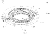
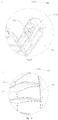
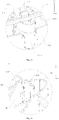
- a dust collection assembly 100 according to embodiments of the present disclosure will be described in detail with reference to Fig. 1 to Fig. 39 .
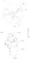
- the dust collection assembly 100 includes: a first annular ring 110, a second annular ring 120, an insulation spacing assembly 130 and an air guide 220.
- a power source for example a high voltage power source 500
- a high potential terminal of the high voltage power source 500 is electrically connected with one of the first annular ring 110 and the second annular ring 120
- a low potential terminal of the high voltage power source 500 is electrically connected with the other one.
- the high potential terminal is electrically connected with the first annular ring 110 by means of the first electrically connecting piece 113
- the low potential terminal is electrically connected with the second annular ring 120 by means of the second electrically connecting piece 123.
- a gas molecule in the air is ionized in the high voltage direct current field, a large amount of electrons and ions are produced and move toward two poles under the function of the electric filed force.
- the electrons and ions come up against the dust particles and bacteria in the airflow and make them charged in the movement.
- the charged particles move to a polar plate in a direction opposite to a component of direction of the airflow under the function of the electric field.
- free ions in the air move towards the two poles.
- current forms between the poles. At first, the free ions in the air are few, and the current is small.
- the ions nearby the discharge pole gains higher energy and speed, and when these ions strike neutral atoms in the air, the neutral atoms are divided into positive and negative ions, which is called air ionization.
- air ionization When the air is ionized, a chain reaction occurs, which makes the number of the ions moving between the poles increases, achieving a sharply increasing current between the poles (which is called corona current).
- corona current which is called corona current.
- the air becomes a conductor, the accompanied bacteria particles are captured by the high and intense voltage, a cell wall made of protein is broken down by the instantaneously conductive phenomenon, as which the purposes of killing bacteria and absorbing and removing dust are realized.
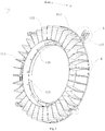
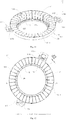
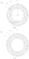
- the first annular ring 110 has a first outer ring 111 and a plurality of first blades 112 disposed on an inner surface of the first outer ring 111 along a circumferential direction of the first annular ring 110.
- the first blade 112 is formed to be a sheet and extends along a radial direction of the first outer ring 111.
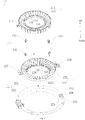
- the second annular ring 120 has a second outer ring 121 and a plurality of second blades 122 disposed on an inner surface of the second outer ring 121 along a circumferential direction of the second annular ring 120. As shown in Fig. 1 - Fig.
- the second annular ring 120 is disposed below the first annular ring 110, and the plurality of second blades 122 and the plurality of first blades 112 are arranged to be staggered in the circumferential direction.
- a plurality of high voltage direct current fields can be formed between the first annular ring 110 and the second annular ring 120, improving the dust removal efficiency of the dust collection assembly 100.
- an air flow channel is formed between the first blade 112 and the adjacent second blade 122, and the first blade 112 and the second blade 122 arranged to be staggered in the circumferential direction has a function to rectify the airflow passing through the dust collection assembly 100, which enhances the uniformity of the airflow, and further reduces the inlet pressure and flow resistance of the airflow, so the noise produced by flowing air is decreased.
- the first annular ring 110 has a first electrically connecting piece 113 configured to be connected with one of a positive pole and a negative pole of a power source
- the second annular ring 120 has a second electrically connecting piece 123 configured to be connected with the other one of the positive pole and the negative pole of the power source.
- the dust and particulate matters in the airflow flowing through the first annular ring 110 and the second annular ring 120 will be captured by the high voltage direct current field, and absorbed to the surface of the first annular ring 110 or the surface of the second annular ring 120, thus the purpose of de-dusting is realized.
- the insulation spacing assembly 130 is disposed between the first annular ring 110 and the second annular ring 120 and spaces the first annular ring 110 and the second annular ring 120 apart.
- the insulation spacing assembly 130 is supported between the first annular ring 110 and the second annular ring 120 so as to make any point of the first annular ring 110 not in direct contact with the second annular ring 120.
- a high voltage electric field can be formed between a face of the first annular ring 110 and an adjacent face of the second annular ring 120 during the use of the dust collection assembly 100, so that the dust collection assembly 100 can collect dust and sterilize air.
- the insulation spacing assembly 130 is detachably connected with the first annular ring 110 as well as the second annular ring 120, as which it is convenient for the users to swept and clean the dust collection assembly 100 when the dust collection assembly 100 needs cleaning.
- the plurality of high voltage direct current fields can be formed between the first annular ring 110 and the second annular ring 120 to improve the dust removal efficiency of the dust collection assembly 100.
- the plurality of first blades 112 and the plurality of second blades 122 have a function to rectify the airflow passing through the dust collection assembly 100, which enhances the uniformity of the airflow, further reduces the inlet pressure and flow resistance of the airflow, so the noise produced by flowing air is decreased.
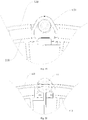
- the air guide 220 is configured to have an annular shape and be fitted over the first annular ring 110 and/or the second annular ring 120, in which an external diameter of an upper end of the air guide 220 is larger than an external diameter of a lower end of the air guide 220.
- the airflow can be guided to places where the first annular ring 110 and the second annular ring 120 are located, as which the dust removal efficiency of the dust collection assembly 100 is improved.
- the air guide 220 is connected with the first annular ring 110 and/or the second annular ring 120 by means of a snap, as which the assembly process of the dust collection assembly 100 is simplified and the assembly efficiency is improved.
- the air guide 220 By disposing the air guide 220 out of the first annular ring 110 and/or the second annular ring 120, the airflow can be guided to the places where the first annular ring 110 and the second annular ring 120 are located, as which the dust removal efficiency of the dust collection assembly 100 is improved. Meanwhile, the air guide 220 is made snap-fitted with the first annular ring 110 and/or the second annular ring 120, the assembly process is simplified and the assembly efficiency is improved.
- the plurality of second blades 122 staggered from the plurality of first blades 112 in the circumferential direction, not only the plurality of high voltage direct current fields are formed between the first annular ring 110 and the second annular ring 120, the effective area of the high voltage direct current fields is also enlarged, as which the dust removal efficiency of the dust collection assembly 100 is improved.
- the plurality of first blades 112 and the plurality of second blades 122 have a function to rectify the airflow passing through the dust collection assembly 100, which enhances the uniformity of the airflow, further reduces the inlet pressure and flow resistance of the airflow, so the noise produced by flowing air is decreased.
- the air guide 220 is connected with the second outer ring 121.
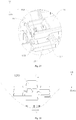
- the air guide 220 is provided with an air guide hook 223, an outer ring connecting terminal 128 extends out of the second outer ring 121, and the outer ring connecting terminal 128 has a step face 1281 fitted with the air guide hook 223.
- the displacement of the outer ring connecting terminal 128 along the up-down direction is limited.
- the outer ring connecting terminal 128 has an opening potion 1282 penetrating through the outer ring connecting terminal 128 along an up-down direction (an up-down direction shown in Fig. 11 ), an inner wall of the opening portion 1282 is provided with a bent plate 1283 which extends downward firstly and then is bent upward, and the step face 1281 is disposed to an outside surface of the bent plate 1283.
- the bent plate 1283 is resilient, and the air guide hook 223 includes a plate body 2231 extending upwards along the axial direction of the air guide 220 and a hook protrusion 2232 above the plate body 2231 and protruding towards the bent plate 1283.
- the outer ring connecting terminal 128 is mounted from up to down, a lower portion of the step face 1281 abuts against the hook protrusion 2232 of the air guide hook 223 firstly, and the bent plate 1283 deforms inwards along the radial direction of the second outer ring 121.
- the bent plate 1283 recovers outwards along the radial direction of the second outer ring 121. At this time, the hook protrusion 2232 is snap-fitted with the bent plate 1283.
- the assembly process of the air guide 220 and the second annular ring 120 is simplified and the connection reliability of the air guide 220 and the second annular ring 120 is improved.
- the air guide 220 is further provided with a first extending plate 224 extending upward and the first extending plate 224 is fitted within the opening potion 1282 and spaced apart from the bent plate 1283 so as to limit a movement of the outer ring connecting terminal 128 along a circumferential direction of the air guide 220.
- the air guide 220 is further provided with a second extending plate 225 extending upward and the second extending plate 225 and the first extending plate 224 define an accommodating groove 226 accommodating an outer end of the outer ring connecting terminal 128 together.
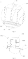
- the air guide 220 may include: a first wind guiding ring 221 and a second wind guiding ring 222.
- the first wind guiding ring 221 extends upward, archwise and gradually from inside to outside along a radial direction.
- the internal diameter of the first wind guiding ring 221 increases gradually from down to up (an up-down direction shown in Fig. 4 ).
- the second wind guiding ring 222 is connected at a lower end of the first wind guiding ring 221, in which an upper surface of the second wind guiding ring 222 is in the same plane.
- At least a portion of the second annular ring 120 is located within the first wind guiding ring 221, and the second annular ring 120 is snap-fitted with the second wind guiding ring 222. Thus, more airflow is guided into the dust collection assembly 100, and the operation efficiency of the dust collection assembly 100 is further improved.
- a shortest distance between the first annular ring 110 and the second annular ring 120 is larger than or equal to 2 mm.
- any point on the first annular ring 110 is away from the second annular ring 120 by larger than or equal to 2mm.
- a distance between the first blade 112 and the adjacent second blade 122 is 2-40mm.
- a thickness of the first blade 112 along the circumferential direction of the first annular ring 110 is larger than 0.5mm, i.e. d1>0.5mm.
- a width of the first blade 112 along an axial direction of the first annular ring 110 is larger than 5mm, i.e. h1>5mm.
- a thickness of the second blade 122 along the circumferential direction of the second annular ring 120 is larger than 0.5mm, i.e. d2>0.5mm.
- a width of the second blade 122 along an axial direction of the second annular ring 120 is larger than 5mm, i.e. h2>5mm.
- the first annular ring 110 is located above the second annular ring 120, in order to guarantee that the first outer ring 111 is spaced apart from the second annular ring 120, in an example shown in Fig. 5 , the first outer ring 111 is connected to an upper end (an up-down direction shown in Fig. 5 ) of the first blade 112, thus making the dust collection assembly 100 have a more compact and reasonable structure.
- the first outer ring 111 is connected to an upper end of the plurality of first blades 112 at a radially outer side of the plurality of first blade s112, and an upper surface of the first blade 112 at the radially outer side is higher than an upper surface of the first blade 112 at a radially inner side.
- the width of the first blade 112 at the radially outer side is larger than the width of the first blade 112 at the radially inner side.
- the lower surfaces of the plurality of first blades 112 are flush with each other and located in a same plane.
- the first annular ring 110 may further include a first inner ring 114.
- the first inner ring 114 is connected to the radially inner side of the plurality of first blades 112.
- the first annular ring 110 further includes a first reinforcing ring 115.
- the first reinforcing ring 115 is connected to an inner surface of the first inner ring 114 by means of a plurality of first reinforcing ribs 116 arranged along a circumferential direction.
- a structural strength of the first annular ring 110 can be enhanced further.
- a lower surface of the second blade 122 at a radially outer side is higher than a lower surface of the second blade 122 at a radially inner side.
- the width of the second blade 122 at the radially outer side is larger than the width of the second blade 122 at the radially inner side.
- the second outer ring 121 is connected to the radially outer side of the plurality of second blades 122.
- the corresponding area of the first blade 112 and the adjacent second blade 122 increases further, as which the area of the high voltage direct current field formed between the first blade 112 and adjacent second blade 122 increases, thus the dust removal efficiency of the dust collection assembly 100 is improved. Meanwhile, the compactness of the dust collection assembly 100 can be improved further. Furthermore, as shown in Fig. 5 and Fig. 7 , the upper surfaces of the plurality of second blades 122 are flush with each other and located in a same plane.
- the second annular ring 120 may further include a second inner ring 124.
- the second inner ring 124 is connected to a lower end of the plurality of second blades 122 at the radially inner side.
- the structure of the second annular ring 120 is more stable.
- the second annular ring 120 may further include a second reinforcing ring 125.
- the second reinforcing ring 125 is connected to an inner surface of the second inner ring 124 by means of a plurality of second reinforcing ribs 126 arranged along a circumferential direction.
- a structural strength of the second annular ring 120 can be enhanced further.
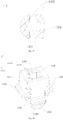
- the insulation spacing assembly 130 includes at least one first insulation snap 131.
- the first insulation snap 131 is mounted to the first outer ring 111 and the second outer ring 121 so as to connect the first outer ring 111 and the second outer ring 121 in a spaced manner.
- any point on the first annular ring 110 can be kept away from the second annular ring 120 by a certain distance so as to prevent air between the first annular ring 110 and the second annular ring 120 from being broken down and prevent discharge in the operation state of the dust collection assembly 100, as a result the stability and security of the dust collection assembly 100 are guaranteed.
- the first insulation snap 131 connect the first outer ring 111 and the second outer ring 121 in a spaced manner, the assembly process of the dust collection assembly 100 is simplified, the assembly efficiency is improved, and the production cost is reduced.
- a circumferential wall of the second outer ring 121 is provided with a location column 1211 to facilitate connection between the first insulation snap 131 and the second outer ring 121.
- the first insulation snap 131 includes a first body 1311, at least two first snap-joint feet 1312 and a first hook 1313.
- the first body 1311 has a height larger than or equal to 2mm in the up-down direction, thus, it is guaranteed that the distance between the first outer ring 111 and the second outer ring 121 is larger than or equal to 2mm so that the air can be prevent from being broken down and the air discharges are prevented between the first outer ring 111 and the second outer ring 121.
- the at least two first snap-joint feet 1312 extend downward from a lower end of the first body 1311 and are fitted over the location column 1211 so as to connect the first body 1311 with the second outer ring 121. As shown in Fig. 26 , each first snap-joint feet 1312 abuts against the lower end face of the location column 1211 so as to limit the location column 1211 between the at least two first snap-joint feet 1312.
- the first hook 1313 extends upward form an upper end of the first body 1311 and is snap-fitted with an edge of the first outer ring 111 so as to connect the first body 1311 and the first outer ring 111.
- the first body 1311 is provided with a through hole 1315 penetrating through the first body 1311 along an up-down direction.
- the first body 1311 may have a tubular shape.
- an upper end face of the first body 1311 includes: a first segment 1316, a second segment 1317 and a connecting segment 1318.
- the first segment 1316 is located at a side away from the first hook 1313 and the first segment 1316 is in a horizontal plane.
- the second segment 1317 is disposed at a side adjacent to the first hook 1313 and the second segment 1317 is located in another horizontal plane lower than the horizontal plane where the first segment 1316 is.
- the connecting segment 1318 is connected between the first segment 1316 and the second segment 1317. In other words, a distance between the connecting segment 1318 and the first hook 1313 increases gradually from down to up.
- the connecting segment 1318 may play a role in guiding to facilitate connection between the first insulation snap 131 and other components, and as a result the assembly efficiency of the first insulation snap 131 is improved.
- the first insulation snap 131 may be made of material having an insulation characteristic, as which two components connected by the first insulation snap 131 are non-conducting between each other, thus the use demand for different components is satisfied.
- a stiffening rib 1314 is connected between the first body 1311 and the first snap-joint foot 1312.
- a plurality of stiffening ribs 1314 may be provided and the stiffening ribs 1314 are distributed on the outer circumferential wall of the first body 1311 at intervals.
- the stiffening rib 1314 is configured to be a triangular stiffening rib, a first side edge of the triangular stiffening rib is connected with the first body 1311, a second side edge of the triangular stiffening rib is connected with the first snap-joint foot 1312.
- the location column 1211 is disposed at an intersection of the second outer ring 121 and one of the second blades 122.
- an outside surface of the first body 1311 away from a center of the first outer ring 111 is configured to be an arcuate face, three first snap-joint feet 1312 are provided, and one of the three first snap-joint feet 1312 is snapped-fitted with an outside of the second outer ring 121 and an outer surface of the one first snap-joint foot is flush with the arcuate face.
- a structural strength of the first insulation snap 131 can be enhanced further, which makes the structure of the first insulation snap 131 more reasonable.
- the first annular ring 110 further includes a first connecting terminal 117, and the first connecting terminal 117 is disposed to a radially outer side of the first outer ring 111.
- the second annular ring 120 further includes second connecting terminal 127, the second connecting terminal 127 is disposed to a radially outer side of the second outer ring 121 and corresponding with the first connecting terminal 117 in the up-down direction.
- the insulation spacing assembly 130 further includes a second insulation snap 132 disposed between the first connecting terminal 117 and the second connecting terminal 127.
- the first connecting terminal 117 is provided with a first snap-joint hole 1171
- an resilient snap 1172 extends downward from a lower surface of the first connecting terminal 11
- the second connecting terminal 127 is provided with a second snap-joint hole 1271.
- the second insulation snap 132 includes a second body 1321, a second hook 1323 and a projection 1324.
- the second body 1321 has a height larger than or equal to 2mm, so that the distance between the first connecting terminal 117 and the second connecting terminal 127 is larger than or equal to 2mm so that air is prevented from being broken down and discharges are prevented between the first connecting terminal 117 and the second connecting terminal 127.
- the second body 1321 is hollow inside, has an opening in a top thereof as well as an opened bottom.
- the resilient snap 1172 goes through the opening, stretches into and is snap-fitted within the second body 1312.
- the projection 1324 extends upwards from the top of the second body 1321 and goes through the first snap-joint hole 1171.
- a cross-section of the projection 1324 in the up-down direction is a rectangular, and the cross-section area of the projection 1324 in the up-down direction increases from up to down.
- second snap-joint feet 1322 extend outwards from two opposite sides of an outer surface of the second body 1321, and the second snap-joint feet 1322 abut against an upper surface of the second connecting terminal 127.
- a second hook 1323a extends downward from a side wall of the second body 1321 between two second snap-joint feet 1322 so as to go through the second snap-joint hole 1271 and be snap-fitted to a bottom surface of the second connecting terminal 127, the second hook 1323 abuts against a lower surface of the second connecting terminal 127.
- the movement of the second insulation snap 132 along the circumferential direction of the second snap-joint hole 1271 is limited.
- the second snap-joint feet 1322 abutting against the upper surface of the second connecting terminal 127 and the second hook 1323 abutting against the lower surface of the second connecting terminal 127 the movement of the second insulation snap 132 along the axial direction of the second snap-joint hole 1271 is limited.
- a cross-section of the second body 1321 in the up-down direction is square.
- a structural strength of the second insulation snap 132 can be enhanced further, which makes the structure of the second insulation snap 132 more compact and reasonable.
- a guiding arcuate face 1326 is formed between a side wall of an opening 1325 and an upper end face of the second body 1321.
- the guiding arcuate face 1326 plays a role in guiding to facilitate fitting and connection between other components and the second insulation snap 132.
- the shape of the opening 1325 is not particularly limited, for example, in an example of the present disclosure, as shown in Fig. 28 , the opening 1325 is configured to be a square hole.
- each second snap-joint foot 1322 is disposed at a place adjacent to a lower end of the side wall of the second body 1321, and the side wall of the second body 1321 below each second snap-joint foot 1322 is configured to be a guiding portion 1327.
- the cross-section area of the guiding portion 1327 decreases gradually in the up-down direction from up to down.
- the guiding portion 1327 can be used to guide the second snap-joint feet 1322 to be fitted with the other components, so that the efficiency of assembling the second insulation snap 132 and the other components can be improved further.
- a guiding slope 1328 is formed between the lower end face of the second hook 1323 and the side wall of the second hook 1323.
- an external diameter of the first outer ring 111 is smaller than or equal to an external diameter of the second outer ring 121.
- At least one of the first annular ring 110 and the second annular ring 120 is configured to be a high-internal-resistance annular ring, and a surface resistivity of the high-internal-resistance annular ring is 10 6 ⁇ 10 12 , that is the surface resistivity of the high-internal-resistance annular ring is 10 6 -10 12 ⁇ •m.
- the second annular ring 120 may be made of low-internal-resistance material such as aluminum or copper.
- the second annular ring 120 is connected with the low potential terminal. Person's health will not be influenced even touching the dust collection assembly 100 as the second annular ring made of the low-internal-resistance material is connected with the low potential terminal and current flows through the human body is limited in a safe range.
- the high-internal-resistance material can limit the current in the first annular ring 110 and the second annular ring 120 within the safe range, and the human safety will not be in a risk when a person touches the dust collection assembly 100, thus the safety performance of the dust collection assembly 100 is improved.
- the high voltage direct current field at least above 2000V it is convenient for the high voltage direct current field at least above 2000V to be formed between the first blade 112 and the adjacent second blade 122, and further, the dust removal efficiency and dust effect of the dust collection assembly 100 can be guaranteed.
- the first annular ring 110 has the first outer ring 111 and the plurality of first blades 112 disposed in the inner surface of the first outer ring 111 along a circumferential direction of the first annular ring 110.
- the first blade 112 includes a first blade body 1121 and a raised portion 1122 of the first blade 112 protruding from one side edge of the first blade body 1121, a side face of the raised portion 1122 of the first blade is flush with a side face of the first blade body 1121.
- the first blade body 1121 and the raised portion 1122 of the first blade extend in the same plane.
- the raised portion 1122 of the first blade is connected with the first outer ring 111.
- the second annular ring 120 has the second outer ring 121 and the plurality of second blades 122 disposed in an inner surface of the second outer ring 121 along a circumferential direction of the second annular ring 120.
- the second blade 122 includes a second blade body 1221 and a raised portion 1222 of the second blade protruding from one side edge of the second blade body 1221, a side face of the raised portion 1222 of the second blade is flush with a side face of the second blade body 1221.
- the second blade body 1221 and the raised portion 1222 of the second blade extend in the same plane.
- the raised portion 1222 of the second blade is connected with the second outer ring 121. As shown in Fig. 1 - Fig.
- the second annular ring 120 is disposed below the first annular ring 110 and the plurality of second blades 122 and the plurality of first blades 112 are arranged to be staggered in the circumferential direction.
- a plurality of high voltage direct current fields can be formed between the first annular ring 110 and the second annular ring 120, and as a result the dust removal efficiency of the dust collection assembly 100 is improved.
- the effective area of the high voltage direct current fields is enlarged, as which the dust removal efficiency of the dust collection assembly 100 is improved.
- a width of the first blade body 1121 along the axial direction of the first annular ring 110 is larger than 5mm. According to an embodiment of the present disclosure, the width of the first blade body 1121 along the axial direction of the first annular ring 110 is 36mm. As shown in Fig.
- the structure of the dust collection assembly 100 is simplified, which makes the structure of the dust collection assembly 100 more compact and reasonable. Meanwhile, hurts can be prevented if someone stretches his finger in to a gap between the first blade 112 and the second blade 122 by mistake.
- the first annular ring 110 is located above the second annular ring 120, in order to guarantee that the first outer ring 111 is spaced apart from the second annular ring 120, in an example shown in Fig. 5 , the first outer ring 111 is connected to the upper end (an up-down direction shown in Fig. 5 ) of the first blade 112, thus, the structure of the dust collection assembly 100 is more compact and reasonable.
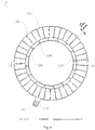
- the thickness of the first blade 112 increases gradually from the radially inner side to the radially outer side and the thickness of the second blade 121 increases gradually from the radially inner side to the radially outer side, in the circumferential direction of the first annular ring 110.
- the corresponding area of the first blade 112 and the second blade 122 can be increased further, an effective high voltage direct current field forms between the first blade 112 and the adjacent second blade 122, so that the dust removal effect of the dust collection assembly 100 is improved and the dust removal efficiency of the dust collection assembly 100 is increased.
- the raised portion 1122 of the first blade is disposed at a place adjacent to an intersection point of two adjacent side edges of the first blade body 1121; the raised portion 1222 of the second blade is disposed at a place adjacent to an intersection point of two adjacent side edges of the second blade body 1221.
- the corresponding area of the first blade 112 and the second blade 122 can be increased further, an effective high voltage direct current field forms between the first blade 112 and the adjacent second blade 122, so that the dust removal effect of the dust collection assembly 100 is improved and the dust removal efficiency of the dust collection assembly 100 is increased.
- both the first blade 112 and the second blade 122 may be configured to be a flat plate, and both the first blade 112 and the second blade 122 may be polygonal, oval or circular. According to an embodiment of the present disclosure, both the first blade 112 and the second blade 122 are rectangular. Thus, the structure of the dust collection assembly 100 is more compact and reasonable. Further, two adjacent side edges of the first blade in the rectangular plate shape are transited smoothly so as to avoid a point discharge, thus the safety performance of the dust collection assembly 100 is improved.
- the shapes of the first blade 112 and the second blade 122 are not limited to this, for example, in an example shown in Fig. 26 , both the first blade 112 and the second blade 122 are configured to be a bent plate and the shape of the cross-section of the first blade 112 corresponds to the shape of the cross-section of the second blade 122 in a direction perpendicular to the axial direction of the first annular ring 110.
- the corresponding area of the first blade 112 and the second blade 122 can be increased further, and areas on the first blade 112 and the second blade 122 where the field can be formed are improved, so that the dust removal efficiency of the dust collection assembly 100 is increased.
- both the cross-sections of the first blade 112 and the second blade 122 have curve shapes in the direction perpendicular to the axial direction of the first annular ring 110, and the first blade 112 and the corresponding second blade 122 have the same radius of curvature.
- the first blade 112 and the second blade 122 having curve-shaped cross-sections further play a role in flow guiding.
- the cross-sections of the first blade 112 and the second blade 122 are both arc.
- the first blade 112 extends along the radial direction of the first annular ring 110 and the second blade 122 extends along the radial direction of the second annular ring 120.
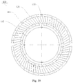
- the extending directions of the first blade 112 and the second blade 122 are not limited to this, for example, in examples shown in Fig. 38 - Fig. 39 , the first blade 112 extends along a direction tilting relative to the radial direction of the first annular ring 110 and the second blade 122 extends along a direction tilting relative to the radial direction of the second annular ring 120.
- any two adjacent faces of the first annular ring 110 are transited smoothly and any two adjacent faces of the second annular ring 120 are transited smoothly.
- the point discharge can be prevented effectively so that the safety performance of the dust collection assembly 100 is improved.
- the air purification device includes the dust collection assembly 100 mentioned above.
- the air guide is disposed out of the first annular ring and/or the second annular ring, the airflow can be guided to the place where the first annular ring 110 and the second annular ring 120 are located, as which the dust removal efficiency of the dust collection assembly 100 is improved. Meanwhile, the air guide 220 is made to be snapped to the first annular ring 110 and/or the second annular ring 120, the assembly process is simplified and the assembly efficiency is improved.
- the plurality of second blades 122 staggered from the plurality of first blades 112 in the circumferential direction, not only a plurality of high voltage direct current fields are formed between the first annular ring 110 and the second annular ring 120, the effective area of the high voltage direct current fields is also enlarged, as which the dust removal efficiency of the dust collection assembly 100 is improved.
- the plurality of first blades 112 and the plurality of second blades 122 have a function to rectify the airflow passing through the dust collection assembly 100, which enhances the uniformity of the airflow, further reduces the inlet pressure and flow resistance of the airflow, so the noise produced by flowing air is decreased.
- the air guide 220 includes the first wind guiding ring 221 and the second wind guiding ring 222.
- the first wind guiding ring 221 extends upward, archwise and gradually from inside to out along a radial direction.
- the internal diameter of the first wind guiding ring 221 increases gradually from down to up (an up-down direction shown in Fig. 4 ).
- the second wind guiding ring 222 is connected to the lower end of the first wind guiding ring 221, and the upper surface of the second wind guiding ring 222 is in the same plane.
- At least a portion of the dust collection assembly 100 is located within the first wind guiding ring 221, and the dust collection assembly 100 is connected with the second wind guiding ring 222.
- the air guide 220 is connected with the second outer ring 121 of the dust collection assembly 100.
- the air guide 220 is provided with a third hook 223, the outer ring connecting terminal 128 extends out of the second outer ring 121, and the outer ring connecting terminal 128 is provided with the step face 1281 fitted with the third hook 223.
- the third hook 223 abutting against the step face 1281, the movement of the outer ring connecting terminal 128 in the up-down direction (an up-down direction shown in Fig. 34 ) is limited.
- the outer ring connecting terminal 128 has the opening potion 1282 penetrating through the outer ring connecting terminal 128 along the up-down direction (the up-down direction shown in Fig. 11 ), the inner wall of the opening portion 1282 is provided with a bent plate 1283 extending downward firstly and then being bent upward, and the step face 1281 is disposed to an outside surface of the bent plate 1283.
- the bent plate 1283 is resilient, and the third hook 223 includes a plate body 2231 extending upwards along the axial direction of the air guide 220 and the hook protrusion 2232 above the plate body 2231 and protruding towards the bent plate 1283.
- the outer ring connecting terminal 128 is mounted from up to down firstly, a lower portion of the step face 1281 abuts against the hook protrusion 2232 of the third hook 223, and the bent plate 1283 deforms inwards along the radial direction of the second outer ring 121.
- the bent plate 1283 recovers outwards along the radial direction of the second outer ring 121.
- the hook protrusion 2232 is snap-fitted with the bent plate 1283.
- the air guide 220 is further provided with the first extending plate 224 extending upward and the first extending plate 224 is fitted within the opening potion 1282 and spaced apart from the bent plate 1283 so as to limit the movement of the outer ring connecting terminal 128 in the circumferential direction of the air guide 220.
- the air guide 220 is further provided with the second extending plate 225 extending upward, and the second extending plate 225 and the first extending plate 224 define an accommodating groove 226 accommodating an outer end of the outer ring connecting terminal 128 together.
- the air conditioner (not shown in the drawings) according to embodiments of the present disclosure includes a casing and the dust collection assembly 100 mentioned above.
- the casing is provided with an air channel so as to define a path of air flowing through the air conditioner.
- a position of the air channel is not defined specifically, for example, the air channel may be located within the casing.
- the air channel has an air inlet and an air outlet, and the air enters the air channel from the air inlet and is discharged out of the air channel from the air outlet.
- the dust collection assembly 100 is disposed in the air channel so as to purify and de-dust the air entering the air channel.
- the dust collection assembly 100 is disposed at a place adjacent to the air inlet or the air outlet. According to an embodiment of the present disclosure, the dust collection assembly 100 is located in a position adjacent to the air inlet.
- the airflow entering the air channel can be purified and de-dusted at first so as to prevent the dust and other particulate matter from being stacked inside of the air channel, which are inconvenient for the user to clean.
- the air conditioner according to embodiments of the present disclosure provided with the above dust collection assembly 100, by disposing the air guide out of the first annular ring and/or the second annular ring, the airflow can be guided to the place where the first annular ring 110 and the second annular ring 120 are located, as which the dust removal efficiency of the dust collection assembly 100 is improved. Meanwhile, through the air guide 220 being snap-fitted with the first annular ring 110 and/or the second annular ring 120, the assembly process is simplified and the assembly efficiency is improved.
- the plurality of second blades 122 interleaved with the plurality of first blades 112 in the circumferential direction, not only a plurality of high voltage direct current fields are formed between the first annular ring 110 and the second annular ring 120, the effective area of the high voltage direct current fields is also enlarged, as which the dust removal efficiency of the dust collection assembly 100 is improved.
- the plurality of first blades 112 and the plurality of second blades 122 have a function to rectify the airflow passing through the dust collection assembly 100, which enhances the uniformity of the airflow, further reduces the inlet pressure and flow resistance of the airflow, so the noise produced by flowing air is decreased.
- the air conditioner may further include a negative ion emission and ionization device (not shown in the drawings).
- the negative ion emission and ionization device is located in the air channel in the flow direction of the air in the air channel so as to pre-charge negative electricity to the airflow and thus making a large amount of the dust and particulate matters in the airflow electronegative.
- the electronegative dust and particulate matters are captured by the high voltage direct current field rapidly when flowing through the air conditioner along with the airflow, thus the dust removal effect is promoted further.
Landscapes
- Engineering & Computer Science (AREA)
- Chemical & Material Sciences (AREA)
- Combustion & Propulsion (AREA)
- Mechanical Engineering (AREA)
- General Engineering & Computer Science (AREA)
- Analytical Chemistry (AREA)
- General Chemical & Material Sciences (AREA)
- Oil, Petroleum & Natural Gas (AREA)
- Chemical Kinetics & Catalysis (AREA)
- Electrostatic Separation (AREA)
- Air Filters, Heat-Exchange Apparatuses, And Housings Of Air-Conditioning Units (AREA)
Abstract
Description
- The present disclosure relates to a technical field of home appliance, and specifically, to a dust collection assembly, an air purification device, and an air conditioner.
- With industrial development, urban construction and an increase in vehicle use, dust increases and air pollution gets worse in outdoor environment, which causes the indoor air to get worse. On the other hand, decoration and smoking are also important reasons for the accumulation of harmful particulate matters in the indoor air. With the improvement of living standards, people's awareness about health increases gradually, higher requirements for an indoor air quality are put forward, so an air conditioner capable of removing PM2.5 is increasingly favored by consumers.
- At present, a traditional air purification device mainly adopts a dense HEPA (High efficiency particulate air) filter net, and particles in the air are blocked to be absorbed by the net when flowing through the dense net. The shortcomings of this dense net are that it needs to be changed frequently as the meshes are easy to plug, and the electric motor of the purification product dedicated to support the use of the HEPA filter net has a large load because of the large loss of resistance, resulting in an increasing electricity consumption, and a loud noise.
- The present disclosure seeks to solve at least one of the technical problems existing in the related art to at least some extent.
- Thus, a dust collection assembly is provided in the present disclosure which has advantages of a lower noise and high dust removal efficiency.
- An air purification device is also provided in the present disclosure which has the dust collection assembly mentioned above.
- An air conditioner is further provided in the present disclosure which has the dust collection assembly mentioned above.
- A dust collection assembly is provided according to embodiments of a first aspect of the present disclosure, which includes: a first annular ring having a first outer ring and a plurality of first blades disposed in an inner surface of the first outer ring along a circumferential direction, in which the first annular ring has a first electrically connecting piece configured to be connected with one of a positive pole and a negative pole of a power source; a second annular ring having a second outer ring and a plurality of second blades disposed in an inner surface of the second outer ring along a circumferential direction, in which the second annular ring is disposed below the first annular ring, the plurality of second blades and the plurality of first blades are arranged to be staggered, and the second annular ring has a second electrically connecting piece configured to be connected with the other one of the positive pole and the negative pole of the power source; an insulation spacing assembly disposed between the first annular ring and the second annular ring and spacing the first annular ring and the second annular ring apart; and an air guide configured to have an annular shape and fitted over the first annular ring and/or the second annular ring, in which the air guide is connected with the first annular ring and/or the second annular ring by means of a snap, and an external diameter of an upper end of the air guide is larger than an external diameter of an lower end of the air guide.
- With the dust collection assembly according to embodiments of the present disclosure, by disposing the air guide out of the first annular ring and/or the second annular ring, the airflow can be guided to a place where the first annular ring and the second annular ring are located, as which the dust removal efficiency of the dust collection assembly is improved. Meanwhile, through the air guide being snap-fitted with the first annular ring and/or the second annular ring, the assembly process is simplified and the assembly efficiency is improved.
- According to some embodiments of the present disclosure, the air guide and the second outer ring are connected with a snap.
- According to some embodiments of the present disclosure, the air guide has an air guide hook, an outer ring connecting terminal extends out of the second outer ring, and outer ring connecting terminal has a step face fitted with the air guide hook.
- According to some embodiments of the present disclosure, the outer ring connecting terminal has an opening potion penetrating through the outer ring connecting terminal along an up-down direction, an inner wall of the opening portion is provided with a bent plate extending downward firstly and then being bent upward, and the step face is disposed to an outside surface of the bent plate.
- According to some embodiments of the present disclosure, the air guide further includes a first extending plate extending upward, and the first extending plate is fitted within the opening potion and spaced apart from the bent plate.
- According to some embodiments of the present disclosure, the air guide further includes a second extending plate extending upward, and the second extending plate and the first extending plate define an accommodating groove accommodating an outer end of the outer ring connecting terminal together.
- According to some embodiments of the present disclosure, the air guide includes: a first wind guiding ring extending upward, archwise and gradually from inside to outside along a radial direction; and a second wind guiding ring connected at an upper end of the first wind guiding ring, in which an upper surface of the second wind guiding ring is in one plane.
- According to some embodiments of the present disclosure, a shortest distance between the first annular ring and the second annular ring is larger than or equal to 2mm.
- According to some embodiments of the present disclosure, a distance between a t first blade and an adjacent second blade is 2-40mm.
- According to some embodiments of the present disclosure, a thickness of the first blade along the circumferential direction of the first annular ring is larger than 0.5mm, and a width of the first blade along an axial direction of the first annular ring is larger than 5mm; and a thickness of the second blade along the circumferential direction of the second annular ring is larger than 0.5mm, and a width of the second blade along an axial direction of the second annular ring is larger than 5mm.
- According to some embodiments of the present disclosure, both of the thicknesses of the first blade and the second blade are 1.5mm, and both of the widths of the first blade and the second blade are 36mm.
- According to some embodiments of the present disclosure, the first outer ring is connected to an upper end of the plurality of first blades.
- According to some embodiments of the present disclosure, the first outer ring is connected to an upper end of the plurality of first blades at a radially outer side of the plurality of first blades, and an upper surface of the plurality of first blades at the radially outer side is higher than an upper surface of the plurality of first blades at a radially inner side.
- According to some embodiments of the present disclosure, the first annular ring further includes a first inner ring connected to the radially inner side of the plurality of first blades.
- According to some embodiments of the present disclosure, the first annular ring further includes a first reinforcing ring connected to an inner surface of the first inner ring by means of a plurality of first reinforcing ribs arranged along a circumferential direction.
- According to some embodiments of the present disclosure, a lower surface of the plurality of second blades at a radially outer side is higher than a lower surface of the plurality of second blades at a radially inner side.
- According to some embodiments of the present disclosure, the second annular ring further includes a second inner ring connected to a lower end of the plurality of second blades at the radially inner side.
- According to some embodiments of the present disclosure, the second annular ring further includes a second reinforcing ring connected to an inner surface of the second inner ring by means of a plurality of second reinforcing ribs arranged along a circumferential direction.
- According to some embodiments of the present disclosure, the insulation spacing assembly includes at least one first insulation snap, and the first insulation snap is mounted to the first outer ring and the second outer ring so as to connect the first outer ring and the second outer ring in a spaced manner.
- According to some embodiments of the present disclosure, a circumferential wall of the second outer ring is provided with a location column, and the first insulation snap includes: a first body having a thickness larger than or equal to 3mm; at least two first snap-joint feet, and the at least two first snap-joint feet extend downward from a lower end of the first body and are fitted over the location column so as to connect the first body with the second outer ring; a first hook extending upward from an upper end of the first body and being snap-fitted with an edge of the first outer ring so as to connect the first body with the first outer ring.
- According to some embodiments of the present disclosure, the location column is disposed at an intersection of the second outer ring and one of the plurality of second blades.
- According to some embodiments of the present disclosure, an outside surface of the first body away from a center of the first outer ring is configured to be an arcuate face, three first snap-joint feet are provided, and one of the three first snap-joint feet is snapped-fitted with an outside of the second outer ring and an outer surface of the one first snap-joint foot is flush with the arcuate face.
- According to some embodiments of the present disclosure, the first annular ring further includes a first connecting terminal disposed to a radially outer side of the first outer ring, and the first electrically connecting piece is disposed on the first connecting terminal. The second annular ring further includes a second connecting terminal disposed to a radially outer side of the second outer ring and corresponding with the first connecting terminal in the up-down direction, and the second electrically connecting piece is disposed on the second connecting terminal. The insulation spacing assembly further includes a second insulation snap disposed between the first connecting terminal and the second connecting terminal.
- According to some embodiments of the present disclosure, the first connecting terminal is provided with a first snap-joint hole, and an resilient snap extends downward from a lower surface of the first connecting terminal; the second connecting terminal is provided with a second snap-joint hole; the second insulation snap includes: a second body having a hollow interior, a thickness larger than or equal to 3mm, and an opening in a top thereof as well as an opened bottom, wherein the resilient snap goes through the opening, stretches into and is snap-fitted within the second body, second snap-joint feet extend outwards from two opposite sides of an outer surface of the second body, and the second snap-joint feet abut against an upper surface of the second connecting terminal; a second hook extending downward from a side wall of the second body between two snap-joint feet so as to go through the second snap-joint hole and be snap-fitted to a bottom surface of the second connecting terminal, the second hook abuts against a lower surface of the second connecting terminal; and a projection extending upwards from the top of the second body and goes through the first snap-joint hole.
- According to some embodiments of the present disclosure, an external diameter of the first outer ring is smaller than or equal to an external diameter of the second outer ring.
- According to some embodiments of the present disclosure, at least one of the first annular ring and the second annular ring is a high-internal-resistance annular ring, and a surface resistivity of the high-internal-resistance annular ring is 106 ∼1012.
- According to some embodiments of the present disclosure, the first blade includes a first blade body and a raised portion of the first blade protruding from one side edge of the first blade body, a side face of the raised portion of the first blade is flush with a side face of the first blade body, and the raised portion of the first blade is connected with the first outer ring, the second blade includes a second blade body and a raised portion of the second blade protruding from one side edge of the second blade body, a side face of the raised portion of the second blade is flush with a side face of the second blade body, and the raised portion of the second blade is connected with the second outer ring.
- According to some embodiments of the present disclosure, in the circumferential direction of the first annular ring, the thickness of the first blade increases gradually from the radially inner side to the radially outer side, and thickness of the second blade increases gradually from the radially inner side to the radially outer side.
- According to some embodiments of the present disclosure, the raised portion of the first blade is disposed at a place adjacent to an intersection point of two adjacent side edges of the first blade body; the raised portion of the second blade is disposed adjacent to an intersection point of two adjacent side edges of the second blade body.
- According to some embodiments of the present disclosure, both the first blade and the second blade are configured to be flat plate, and both the first blade and the second blade are polygonal, oval or circular.
- According to some embodiments of the present disclosure, both the first blade and the second blade are rectangular.
- According to some embodiments of the present disclosure, both the first blade and the second blade are configured to be bent plate, and a shape of a cross-section of the first blade corresponds to a shape of a cross-section of the second blade in a direction perpendicular to the axial direction of the first annular ring.
- According to some embodiments of the present disclosure, the shape of the cross-section of the first blade and the shape of the cross-section of the second blade are both formed to be curve shapes in the direction perpendicular to the axial direction of the first annular ring, and the first blade and the corresponding second blade have the same curvature radius.
- According to some embodiments of the present disclosure, the cross-section of the first blade and the cross-section of the second blade are both arc.
- According to some embodiments of the present disclosure, the plurality of first blades extend along a radial direction of the first annular ring and the plurality of second blades extend along a radial direction of the second annular ring.
- According to some embodiments of the present disclosure, the plurality of first blades extend along a direction tilting relative to the radial direction of the first annular ring and the plurality of second blades extend along a direction tilted relative to the radial direction of the second annular ring.
- According to some embodiments of the present disclosure, any two adjacent faces of the first annular ring are transited smoothly and any two adjacent faces of the second annular ring are transited smoothly.
- An air purification device is provided according to embodiments of the second aspect of the present disclosure, which includes the dust collection assembly mentioned above.
- With the air purification device according to embodiments of the present disclosure provided with the dust collection assembly mentioned above, the dust removal efficiency of air purification device can be improved, thus the product quality is promoted.
- An air conditioner is provided according to embodiments of the third aspect of the present disclosure, which includes a casing having an air channel, in which the air channel has an air inlet and an air outlet; and the dust collection assembly mentioned above, in which the dust collection assembly is disposed in the air channel and located in a position adjacent to the air inlet or the air outlet.
- With the air conditioner according to embodiments of the present disclosure provided with the dust collection assembly mentioned above, the dust removal efficiency of air purification device can be improved, thus the product quality is promoted.
- According to some embodiments of the present disclosure, the air conditioner further includes a negative ion emission and ionization device disposed in the air channel.
- Additional aspects and advantages of embodiments of present disclosure will be given in part in the following descriptions, become apparent in part from the following descriptions, or be learned from the practice of the embodiments of the present disclosure.
- These and other aspects and advantages of embodiments of the present disclosure will become apparent and more readily appreciated from the following descriptions made with reference to the drawings, in which:
-
Fig. 1 is a perspective view of a dust collection assembly according to an embodiment of the present disclosure; -
Fig. 2 is a schematic view of the dust collection assembly inFig. 1 connected with a high voltage power source; -
Fig. 3 is a perspective view of an air purification device according to an embodiment of the present disclosure; -
Fig. 4 is an exploded schematic view of the air purification device inFig. 3 ; -
Fig. 5 is a perspective view of a first annular ring inFig. 4 ; -
Fig. 6 andFig. 7 are a front view and a right view of the first annular ring inFig. 5 respectively; -
Fig .8 is a sectional view ofFig. 6 along M-M direction; -
Fig. 9 and Fig. 10 are partial enlarged views of areas A and B inFig.5 respectively; -
Fig. 11 is a perspective view of a second annular ring inFig.4 ; -
Fig. 12 andFig. 13 are a front view and a right view of the second annular ring inFig. 11 respectively; -
Fig. 14 is a sectional view ofFig. 12 along N-N direction; -
Fig. 15 is a partial enlarged view of area C inFig. 11 ; -
Fig. 16 is a partial enlarged view ofFig. 11 ; -
Fig. 17 and Fig. 18 are partial enlarged views of areas D and E inFig.3 respectively; -
Fig. 19 and Fig. 20 are partial enlarged views ofFig. 1 , in which the first insulation snap is fitted with the first annular ring and the second annular ring; -
Fig. 21 is a partial enlarged view of area F inFig. 4 ; -
Fig. 22 is a perspective view of the first insulation snap inFig. 4 ; -
Figs. 23-25 are a front view, a left view and a top view of the first insulation snap inFig. 22 respectively; -
Fig. 26 andFig. 27 are sectional views ofFig. 23 along P-P and T-T directions respectively; -
Fig. 28 is a perspective view of the second insulation snap inFig. 4 ; -
Fig. 29 is a partial enlarged view of area G inFig. 3 ; -
Fig. 30 is a partial enlarged view of a fitting place between an outer ring connecting terminal and an air guide inFig. 3 ; -
Fig .31 is a sectional view ofFig. 30 along X-X direction; -
Fig. 32 is a partial enlarged view of area H inFig. 3 ; -
Fig. 33 is the partial enlarged view of the fitting place between the outer ring connecting terminal and the air guide inFig. 32 in another perspective; -
Fig .34 is a sectional view ofFig. 33 along Y-Y direction; -
Fig. 35 is a schematic view of the dust collection assembly according to embodiments of the present disclosure; -
Fig. 36 is a schematic view of the dust collection assembly according to embodiments of the present disclosure; -
Fig. 37 is a schematic view of the dust collection assembly according to embodiments of the present disclosure; -
Fig. 38 is a schematic view of the dust collection assembly according to embodiments of the present disclosure; -
Fig. 39 is a schematic view of the dust collection assembly according to embodiments of the present disclosure. -
-
dust collection assembly 100, - first
annular ring 110, - first
outer ring 111,first blade 112,first blade body 1121, raisedportion 1122 of the first blade, first electrically connectingpiece 113, firstinner ring 114, - first reinforcing
ring 115, first reinforcingrib 116, - first connecting
terminal 117, first snap-joint hole 1171,resilient snap 1172, - second
annular ring 120, - second
outer ring 121,location column 1211, -
second blade 122,second blade body 1221, raisedportion 1222 of the second blade, second electrically connectingpiece 123, secondinner ring 124, second reinforcingring 125, - second reinforcing
rib 126, second connectingterminal 127, second snap-joint hole 1271, - outer
ring connecting terminal 128,step face 1281,opening potion 1282,bent plate 1283, -
insulation spacing assembly 130, -
first insulation snap 131,first body 1311, first snap-joint foot 1312,first hook 1313, - stiffening
rib 1314, throughhole 1315,first segment 1316,second segment 1317, connectingsegment 1318, -
second insulation snap 132,second body 1321, second snap-joint foot 1322, -
second hook 1323,projection 1324, opening 1325, guidingarcuate face 1326, guidingportion 1327, guidingslope 1328, -
air guide 220, - first
wind guiding ring 221, secondwind guiding ring 222, -
third hook 223,plate body 2231,hook protrusion 2232, - first extending
plate 224, second extendingplate 225,accommodating groove 226, - high
voltage power source 500. - Embodiments of the present disclosure will be described in detail in the following. Examples of the embodiments are shown in the drawings, and the same or similar elements and the elements having same or similar functions are denoted by like reference numerals throughout the descriptions. The embodiments described with reference to the drawings are illustrative, which is only used to explain the present disclosure and shouldn't be construed to limit the present disclosure.
- In the specification, it is to be understood that terms such as "central," "longitudinal," "lateral," "length," "width," "thickness," "upper," "lower," "front," "rear," "left," "right," "vertical," "horizontal," "top," "bottom," "inner," "outer," "clockwise," "counterclockwise" "axial direction," "radial direction," and "circumferential direction" should be construed to refer to the orientation as then described or as shown in the drawings under discussion. These relative terms are for convenience of description and do not require that the present invention be constructed or operated in a particular orientation, thus cannot be construed to limit the present disclosure. In addition, terms such as "first" and "second" are used herein for purposes of description and are not intended to indicate or imply relative importance or significance or to imply the number of indicated technical features. Thus, the feature defined with "first" and "second" may comprise one or more of this feature. In the description of the present invention, "a plurality of" means two or more than two, unless specified otherwise.
- In the present invention, unless specified or limited otherwise, the terms "mounted," "connected," "coupled," should be understood broadly, and may be, for example, fixed connections, detachable connections, or integral connections; may also be mechanical or electrical connections; may also be direct connections or indirect connections via intervening structures; may also be inner communications of two elements, which can be understood by those skilled in the art according to specific situations.
- A
dust collection assembly 100 according to embodiments of the present disclosure will be described in detail with reference toFig. 1 to Fig. 39 . - As shown in
Fig. 1 - Fig. 4 , thedust collection assembly 100 according to embodiments of the present disclosure includes: a firstannular ring 110, a secondannular ring 120, aninsulation spacing assembly 130 and anair guide 220. - As shown in
Fig. 2 , during the use of thedust collection assembly 100, it can be connected with a power source (for example a high voltage power source 500), a high potential terminal of the highvoltage power source 500 is electrically connected with one of the firstannular ring 110 and the secondannular ring 120, a low potential terminal of the highvoltage power source 500 is electrically connected with the other one. For example, in an example of the present disclosure, the high potential terminal is electrically connected with the firstannular ring 110 by means of the first electrically connectingpiece 113 and the low potential terminal is electrically connected with the secondannular ring 120 by means of the second electrically connectingpiece 123. When the firstannular ring 110, the secondannular ring 120 and the highvoltage power source 500 are switched on, a high voltage direct current field is formed between any two adjacent faces of the spaced firstannular ring 110 and secondannular ring 120. - It should be illustrated that, a gas molecule in the air is ionized in the high voltage direct current field, a large amount of electrons and ions are produced and move toward two poles under the function of the electric filed force. The electrons and ions come up against the dust particles and bacteria in the airflow and make them charged in the movement. The charged particles move to a polar plate in a direction opposite to a component of direction of the airflow under the function of the electric field. Under the function of the electric filed, free ions in the air move towards the two poles. The higher the voltage, the higher the electric field intensity, and the faster the movement speed of the ions. As the movement of the ions, current forms between the poles. At first, the free ions in the air are few, and the current is small. When the voltage rises to a certain value, the ions nearby the discharge pole gains higher energy and speed, and when these ions strike neutral atoms in the air, the neutral atoms are divided into positive and negative ions, which is called air ionization. When the air is ionized, a chain reaction occurs, which makes the number of the ions moving between the poles increases, achieving a sharply increasing current between the poles (which is called corona current). Thus, the air becomes a conductor, the accompanied bacteria particles are captured by the high and intense voltage, a cell wall made of protein is broken down by the instantaneously conductive phenomenon, as which the purposes of killing bacteria and absorbing and removing dust are realized.
- Specifically, the first
annular ring 110 has a firstouter ring 111 and a plurality offirst blades 112 disposed on an inner surface of the firstouter ring 111 along a circumferential direction of the firstannular ring 110. In an example of the present disclosure, thefirst blade 112 is formed to be a sheet and extends along a radial direction of the firstouter ring 111. The secondannular ring 120 has a secondouter ring 121 and a plurality ofsecond blades 122 disposed on an inner surface of the secondouter ring 121 along a circumferential direction of the secondannular ring 120. As shown inFig. 1 - Fig. 4 , the secondannular ring 120 is disposed below the firstannular ring 110, and the plurality ofsecond blades 122 and the plurality offirst blades 112 are arranged to be staggered in the circumferential direction. Thus, a plurality of high voltage direct current fields can be formed between the firstannular ring 110 and the secondannular ring 120, improving the dust removal efficiency of thedust collection assembly 100. - In addition, an air flow channel is formed between the
first blade 112 and the adjacentsecond blade 122, and thefirst blade 112 and thesecond blade 122 arranged to be staggered in the circumferential direction has a function to rectify the airflow passing through thedust collection assembly 100, which enhances the uniformity of the airflow, and further reduces the inlet pressure and flow resistance of the airflow, so the noise produced by flowing air is decreased. - The first
annular ring 110 has a first electrically connectingpiece 113 configured to be connected with one of a positive pole and a negative pole of a power source, the secondannular ring 120 has a second electrically connectingpiece 123 configured to be connected with the other one of the positive pole and the negative pole of the power source. Thus, with the first electrically connectingpiece 113 and the second electrically connectingpiece 123, it is guaranteed that the firstannular ring 110 and the secondannular ring 120 are in reliable connection with the highvoltage power source 500. When thedust collection assembly 100 is connected with the highvoltage power source 500, the dust and particulate matters in the airflow flowing through the firstannular ring 110 and the secondannular ring 120 will be captured by the high voltage direct current field, and absorbed to the surface of the firstannular ring 110 or the surface of the secondannular ring 120, thus the purpose of de-dusting is realized. - The
insulation spacing assembly 130 is disposed between the firstannular ring 110 and the secondannular ring 120 and spaces the firstannular ring 110 and the secondannular ring 120 apart. In other words, theinsulation spacing assembly 130 is supported between the firstannular ring 110 and the secondannular ring 120 so as to make any point of the firstannular ring 110 not in direct contact with the secondannular ring 120. Thus, it is guaranteed that a high voltage electric field can be formed between a face of the firstannular ring 110 and an adjacent face of the secondannular ring 120 during the use of thedust collection assembly 100, so that thedust collection assembly 100 can collect dust and sterilize air. According to an embodiment of the present disclosure, theinsulation spacing assembly 130 is detachably connected with the firstannular ring 110 as well as the secondannular ring 120, as which it is convenient for the users to swept and clean thedust collection assembly 100 when thedust collection assembly 100 needs cleaning. - Accordingly, with the plurality of
second blades 122 and the plurality offirst blade 112 arranged to be staggered in the circumferential direction, the plurality of high voltage direct current fields can be formed between the firstannular ring 110 and the secondannular ring 120 to improve the dust removal efficiency of thedust collection assembly 100. In addition, the plurality offirst blades 112 and the plurality ofsecond blades 122 have a function to rectify the airflow passing through thedust collection assembly 100, which enhances the uniformity of the airflow, further reduces the inlet pressure and flow resistance of the airflow, so the noise produced by flowing air is decreased. - The
air guide 220 is configured to have an annular shape and be fitted over the firstannular ring 110 and/or the secondannular ring 120, in which an external diameter of an upper end of theair guide 220 is larger than an external diameter of a lower end of theair guide 220. Thus, the airflow can be guided to places where the firstannular ring 110 and the secondannular ring 120 are located, as which the dust removal efficiency of thedust collection assembly 100 is improved. In addition, theair guide 220 is connected with the firstannular ring 110 and/or the secondannular ring 120 by means of a snap, as which the assembly process of thedust collection assembly 100 is simplified and the assembly efficiency is improved. - With the
dust collection assembly 100 according to embodiments of the present disclosure, by disposing theair guide 220 out of the firstannular ring 110 and/or the secondannular ring 120, the airflow can be guided to the places where the firstannular ring 110 and the secondannular ring 120 are located, as which the dust removal efficiency of thedust collection assembly 100 is improved. Meanwhile, theair guide 220 is made snap-fitted with the firstannular ring 110 and/or the secondannular ring 120, the assembly process is simplified and the assembly efficiency is improved. - Meanwhile, by making the plurality of
second blades 122 staggered from the plurality offirst blades 112 in the circumferential direction, not only the plurality of high voltage direct current fields are formed between the firstannular ring 110 and the secondannular ring 120, the effective area of the high voltage direct current fields is also enlarged, as which the dust removal efficiency of thedust collection assembly 100 is improved. In addition, the plurality offirst blades 112 and the plurality ofsecond blades 122 have a function to rectify the airflow passing through thedust collection assembly 100, which enhances the uniformity of the airflow, further reduces the inlet pressure and flow resistance of the airflow, so the noise produced by flowing air is decreased. - In an example of the present disclosure, as shown in
Fig. 3 - Fig. 4 , theair guide 220 is connected with the secondouter ring 121. Thus, it is convenient for the connection between theair guide 220 and the secondannular ring 120. In examples shown inFig. 30 - Fig. 34 , theair guide 220 is provided with anair guide hook 223, an outerring connecting terminal 128 extends out of the secondouter ring 121, and the outerring connecting terminal 128 has astep face 1281 fitted with theair guide hook 223. With theair guide hook 223 abutting against thestep face 1281, the displacement of the outerring connecting terminal 128 along the up-down direction (an up-down direction shown inFig. 34 ) is limited. - As shown in
Fig. 11 andFig. 34 , the outerring connecting terminal 128 has anopening potion 1282 penetrating through the outerring connecting terminal 128 along an up-down direction (an up-down direction shown inFig. 11 ), an inner wall of theopening portion 1282 is provided with abent plate 1283 which extends downward firstly and then is bent upward, and thestep face 1281 is disposed to an outside surface of thebent plate 1283. It should be understood that, in the radial direction of the secondouter ring 121, thebent plate 1283 is resilient, and theair guide hook 223 includes aplate body 2231 extending upwards along the axial direction of theair guide 220 and ahook protrusion 2232 above theplate body 2231 and protruding towards thebent plate 1283. During the assembling, the outerring connecting terminal 128 is mounted from up to down, a lower portion of thestep face 1281 abuts against thehook protrusion 2232 of theair guide hook 223 firstly, and thebent plate 1283 deforms inwards along the radial direction of the secondouter ring 121. When thestep face 1281 abuts against the lower end face of thehook protrusion 2232, thebent plate 1283 recovers outwards along the radial direction of the secondouter ring 121. At this time, thehook protrusion 2232 is snap-fitted with thebent plate 1283. Thus, the assembly process of theair guide 220 and the secondannular ring 120 is simplified and the connection reliability of theair guide 220 and the secondannular ring 120 is improved. - Further, as shown in
Fig. 4 , theair guide 220 is further provided with a first extendingplate 224 extending upward and the first extendingplate 224 is fitted within theopening potion 1282 and spaced apart from thebent plate 1283 so as to limit a movement of the outerring connecting terminal 128 along a circumferential direction of theair guide 220. Furthermore, as shown inFig. 4 andFig. 32 , theair guide 220 is further provided with a second extendingplate 225 extending upward and the second extendingplate 225 and the first extendingplate 224 define anaccommodating groove 226 accommodating an outer end of the outer ring connecting terminal 128 together. Thus, the connection reliability between the outerring connecting terminal 128 and theair guide 220 can be improved further. - According to some embodiments of the present disclosure, as shown in
Fig. 4 , theair guide 220 may include: a firstwind guiding ring 221 and a secondwind guiding ring 222. Specifically, the firstwind guiding ring 221 extends upward, archwise and gradually from inside to outside along a radial direction. For example, in an example as shown inFig. 4 , the internal diameter of the firstwind guiding ring 221 increases gradually from down to up (an up-down direction shown inFig. 4 ). The secondwind guiding ring 222 is connected at a lower end of the firstwind guiding ring 221, in which an upper surface of the secondwind guiding ring 222 is in the same plane. At least a portion of the secondannular ring 120 is located within the firstwind guiding ring 221, and the secondannular ring 120 is snap-fitted with the secondwind guiding ring 222. Thus, more airflow is guided into thedust collection assembly 100, and the operation efficiency of thedust collection assembly 100 is further improved. - According to an embodiment of the present disclosure, a shortest distance between the first
annular ring 110 and the secondannular ring 120 is larger than or equal to 2 mm. In other words, any point on the firstannular ring 110 is away from the secondannular ring 120 by larger than or equal to 2mm. Thus, during use of thedust collection assembly 100, air can be prevented from being broken down, discharge and short circuit can be prevented effectively, so that the operation stability of thedust collection assembly 100 is improved and the security coefficient and dust removal effect are guaranteed. According to an embodiment of the present disclosure, a distance between thefirst blade 112 and the adjacentsecond blade 122 is 2-40mm. Thus, during the use of thedust collection assembly 100, air can be prevented from being broken down, and discharge and short circuit can be prevented, so that the operation stability of thedust collection assembly 100 is improved more and the security coefficient and dust removal effect are guaranteed. Meanwhile, hurts can be prevented if someone stretches his finger into a gap between thefirst blade 112 and thesecond blade 122 by mistake. - In an example of the present disclosure, as shown in
Fig. 6 , a thickness of thefirst blade 112 along the circumferential direction of the firstannular ring 110 is larger than 0.5mm, i.e. d1>0.5mm. As shown inFig. 8 , a width of thefirst blade 112 along an axial direction of the firstannular ring 110 is larger than 5mm, i.e. h1>5mm. As shown inFig. 12 , a thickness of thesecond blade 122 along the circumferential direction of the secondannular ring 120 is larger than 0.5mm, i.e. d2>0.5mm. As shown inFig. 14 , a width of thesecond blade 122 along an axial direction of the secondannular ring 120 is larger than 5mm, i.e. h2>5mm. Thus, the purification effect of thedust collection assembly 100 is guaranteed, the purification efficiency of thedust collection assembly 100 is improved, and the structure of thedust collection assembly 100 is simplified, which makes the structure of thedust collection assembly 100 more compact and reasonable. - Considering that the first
annular ring 110 is located above the secondannular ring 120, in order to guarantee that the firstouter ring 111 is spaced apart from the secondannular ring 120, in an example shown inFig. 5 , the firstouter ring 111 is connected to an upper end (an up-down direction shown inFig. 5 ) of thefirst blade 112, thus making thedust collection assembly 100 have a more compact and reasonable structure. - Further, as shown in
Fig. 5 ,Fig. 6 ,Fig. 8 andFig. 10 , the firstouter ring 111 is connected to an upper end of the plurality offirst blades 112 at a radially outer side of the plurality of first blade s112, and an upper surface of thefirst blade 112 at the radially outer side is higher than an upper surface of thefirst blade 112 at a radially inner side. In other words, in the axial direction of the firstannular ring 110, the width of thefirst blade 112 at the radially outer side is larger than the width of thefirst blade 112 at the radially inner side. Thus, the compactness of thedust collection assembly 100 is improved. Furthermore, as shown inFig. 5 andFig. 7 , the lower surfaces of the plurality offirst blades 112 are flush with each other and located in a same plane. - In examples shown in
Fig. 5 - Fig. 10 , the firstannular ring 110 may further include a firstinner ring 114. The firstinner ring 114 is connected to the radially inner side of the plurality offirst blades 112. Thus, the structure of the firstannular ring 110 is more stable. Further, as shown inFig. 5 - Fig. 6 , the firstannular ring 110 further includes a first reinforcingring 115. The first reinforcingring 115 is connected to an inner surface of the firstinner ring 114 by means of a plurality of first reinforcingribs 116 arranged along a circumferential direction. Thus, a structural strength of the firstannular ring 110 can be enhanced further. - Similarly, in examples shown in
Fig. 11 - Fig. 15 , a lower surface of thesecond blade 122 at a radially outer side is higher than a lower surface of thesecond blade 122 at a radially inner side. In other words, in the axial direction of the secondannular ring 120, the width of thesecond blade 122 at the radially outer side is larger than the width of thesecond blade 122 at the radially inner side. The secondouter ring 121 is connected to the radially outer side of the plurality ofsecond blades 122. When the secondannular ring 120 is fitted with the firstannular ring 110, the corresponding area of thefirst blade 112 and the adjacentsecond blade 122 increases further, as which the area of the high voltage direct current field formed between thefirst blade 112 and adjacentsecond blade 122 increases, thus the dust removal efficiency of thedust collection assembly 100 is improved. Meanwhile, the compactness of thedust collection assembly 100 can be improved further. Furthermore, as shown inFig. 5 andFig. 7 , the upper surfaces of the plurality ofsecond blades 122 are flush with each other and located in a same plane. - In examples shown in
Fig. 11 - Fig. 15 , the secondannular ring 120 may further include a secondinner ring 124. The secondinner ring 124 is connected to a lower end of the plurality ofsecond blades 122 at the radially inner side. Thus, the structure of the secondannular ring 120 is more stable. Further, as shown inFig. 11 - Fig. 15 , the secondannular ring 120 may further include a second reinforcingring 125. The second reinforcingring 125 is connected to an inner surface of the secondinner ring 124 by means of a plurality of second reinforcingribs 126 arranged along a circumferential direction. Thus, a structural strength of the secondannular ring 120 can be enhanced further. - As shown in
Fig. 4 ,Fig. 17 - Fig. 27 , according to an embodiment of the present disclosure, theinsulation spacing assembly 130 includes at least onefirst insulation snap 131. Thefirst insulation snap 131 is mounted to the firstouter ring 111 and the secondouter ring 121 so as to connect the firstouter ring 111 and the secondouter ring 121 in a spaced manner. Thus, any point on the firstannular ring 110 can be kept away from the secondannular ring 120 by a certain distance so as to prevent air between the firstannular ring 110 and the secondannular ring 120 from being broken down and prevent discharge in the operation state of thedust collection assembly 100, as a result the stability and security of thedust collection assembly 100 are guaranteed. In addition, by making thefirst insulation snap 131 connect the firstouter ring 111 and the secondouter ring 121 in a spaced manner, the assembly process of thedust collection assembly 100 is simplified, the assembly efficiency is improved, and the production cost is reduced. - In examples shown in
Fig. 11- Fig. 13 , a circumferential wall of the secondouter ring 121 is provided with alocation column 1211 to facilitate connection between thefirst insulation snap 131 and the secondouter ring 121. In addition, as shown inFig. 22 - Fig. 26 , thefirst insulation snap 131 includes afirst body 1311, at least two first snap-joint feet 1312 and afirst hook 1313. Thefirst body 1311 has a height larger than or equal to 2mm in the up-down direction, thus, it is guaranteed that the distance between the firstouter ring 111 and the secondouter ring 121 is larger than or equal to 2mm so that the air can be prevent from being broken down and the air discharges are prevented between the firstouter ring 111 and the secondouter ring 121. - In examples shown in
Fig. 11 andFig. 17 - Fig. 27 , the at least two first snap-joint feet 1312 extend downward from a lower end of thefirst body 1311 and are fitted over thelocation column 1211 so as to connect thefirst body 1311 with the secondouter ring 121. As shown inFig. 26 , each first snap-joint feet 1312 abuts against the lower end face of thelocation column 1211 so as to limit thelocation column 1211 between the at least two first snap-joint feet 1312. For the convenience of the connection between thefirst insulation snap 131 and the firstouter ring 111, thefirst hook 1313 extends upward form an upper end of thefirst body 1311 and is snap-fitted with an edge of the firstouter ring 111 so as to connect thefirst body 1311 and the firstouter ring 111. - As shown in
Fig. 23 ,Fig. 25 andFig. 27 , thefirst body 1311 is provided with a throughhole 1315 penetrating through thefirst body 1311 along an up-down direction. In other words, thefirst body 1311 may have a tubular shape. Thus, on the premise that the structural strength of thefirst insulation snap 131 is ensured, the structure of thefirst insulation snap 131 is further simplified, the weight of thefirst insulation snap 131 is also reduced, and the production cost is decreased. - As shown in
Fig. 23 , in an embodiment of the present disclosure, an upper end face of thefirst body 1311 includes: afirst segment 1316, asecond segment 1317 and a connectingsegment 1318. Thefirst segment 1316 is located at a side away from thefirst hook 1313 and thefirst segment 1316 is in a horizontal plane. Thesecond segment 1317 is disposed at a side adjacent to thefirst hook 1313 and thesecond segment 1317 is located in another horizontal plane lower than the horizontal plane where thefirst segment 1316 is. The connectingsegment 1318 is connected between thefirst segment 1316 and thesecond segment 1317. In other words, a distance between the connectingsegment 1318 and thefirst hook 1313 increases gradually from down to up. Thus, when thefirst hook 1313 is connected with other components, the connectingsegment 1318 may play a role in guiding to facilitate connection between thefirst insulation snap 131 and other components, and as a result the assembly efficiency of thefirst insulation snap 131 is improved. - As shown in
Fig. 23 and Fig. 24 , thefirst insulation snap 131 may be made of material having an insulation characteristic, as which two components connected by thefirst insulation snap 131 are non-conducting between each other, thus the use demand for different components is satisfied. In order to improve the structure strength of thefirst insulation snap 131, astiffening rib 1314 is connected between thefirst body 1311 and the first snap-joint foot 1312. In an example shown inFig. 24 , a plurality of stiffeningribs 1314 may be provided and thestiffening ribs 1314 are distributed on the outer circumferential wall of thefirst body 1311 at intervals. In an example of the present disclosure, thestiffening rib 1314 is configured to be a triangular stiffening rib, a first side edge of the triangular stiffening rib is connected with thefirst body 1311, a second side edge of the triangular stiffening rib is connected with the first snap-joint foot 1312. - In order to improve the strength of connection between the
first insulation snap 131 and the secondannular ring 120, in an example shown inFig. 21 , thelocation column 1211 is disposed at an intersection of the secondouter ring 121 and one of thesecond blades 122. - Furthermore, as shown in
Fig. 22 , an outside surface of thefirst body 1311 away from a center of the firstouter ring 111 is configured to be an arcuate face, three first snap-joint feet 1312 are provided, and one of the three first snap-joint feet 1312 is snapped-fitted with an outside of the secondouter ring 121 and an outer surface of the one first snap-joint foot is flush with the arcuate face. Thus, a structural strength of thefirst insulation snap 131 can be enhanced further, which makes the structure of thefirst insulation snap 131 more reasonable. - According to an embodiment of the present disclosure, as shown in
Fig. 5 ,Fig. 6 andFig. 9 , the firstannular ring 110 further includes a first connectingterminal 117, and the first connectingterminal 117 is disposed to a radially outer side of the firstouter ring 111. As shown inFig. 11- Fig. 12 , the secondannular ring 120 further includes second connectingterminal 127, the second connectingterminal 127 is disposed to a radially outer side of the secondouter ring 121 and corresponding with the first connectingterminal 117 in the up-down direction. For the convenience of connection between the firstannular ring 110 and the highvoltage power source 500 and connection between the secondannular ring 120 and the highvoltage power source 500, the first electrically connectingpiece 113 is disposed on the first connectingterminal 117, and the second electrically connectingpiece 123 is disposed on the second connectingterminal 127. Further, in order to prevent the first connecting terminal 117 from contacting the second connectingterminal 127, as shown inFig. 28 - Fig. 29 , theinsulation spacing assembly 130 further includes asecond insulation snap 132 disposed between the first connectingterminal 117 and the second connectingterminal 127. - In examples shown in
Fig. 5 - Fig. 6 ,Fig. 11 - Fig. 12 andFig. 28 - Fig. 29 , for the convenience of connection between thesecond insulation snap 132 and the first connectingterminal 117 and connection between thesecond insulation snap 132 and the second connectingterminal 127, the first connectingterminal 117 is provided with a first snap-joint hole 1171, anresilient snap 1172 extends downward from a lower surface of the first connecting terminal 11, and the second connectingterminal 127 is provided with a second snap-joint hole 1271. Thesecond insulation snap 132 includes asecond body 1321, asecond hook 1323 and aprojection 1324. Thesecond body 1321 has a height larger than or equal to 2mm, so that the distance between the first connectingterminal 117 and the second connectingterminal 127 is larger than or equal to 2mm so that air is prevented from being broken down and discharges are prevented between the first connectingterminal 117 and the second connectingterminal 127. - As shown in
Fig. 28 , thesecond body 1321 is hollow inside, has an opening in a top thereof as well as an opened bottom. Theresilient snap 1172 goes through the opening, stretches into and is snap-fitted within thesecond body 1312. Theprojection 1324 extends upwards from the top of thesecond body 1321 and goes through the first snap-joint hole 1171. Thus, it is guaranteed that thesecond insulation snap 132 and the first connectingterminal 117 are in reliable connection. As shown inFig. 28 , in an example of the present disclosure, a cross-section of theprojection 1324 in the up-down direction is a rectangular, and the cross-section area of theprojection 1324 in the up-down direction increases from up to down. Thus, it is convenient for theprojection 1324 to be fitted with other components. - As shown in
Fig. 28 andFig. 29 , second snap-joint feet 1322 extend outwards from two opposite sides of an outer surface of thesecond body 1321, and the second snap-joint feet 1322 abut against an upper surface of the second connectingterminal 127. A second hook 1323a extends downward from a side wall of thesecond body 1321 between two second snap-joint feet 1322 so as to go through the second snap-joint hole 1271 and be snap-fitted to a bottom surface of the second connectingterminal 127, thesecond hook 1323 abuts against a lower surface of the second connectingterminal 127. As the second snap-joint feet 1322 and thesecond hook 1323 are snapped into the second snap-joint hole 1271, the movement of thesecond insulation snap 132 along the circumferential direction of the second snap-joint hole 1271 is limited. With the second snap-joint feet 1322 abutting against the upper surface of the second connectingterminal 127 and thesecond hook 1323 abutting against the lower surface of the second connectingterminal 127, the movement of thesecond insulation snap 132 along the axial direction of the second snap-joint hole 1271 is limited. Thus, it is guaranteed that thesecond insulation snap 132 and the second connectingterminal 127 are in reliable connection. - As shown in
Fig. 28 , in an embodiment of the present disclosure, a cross-section of thesecond body 1321 in the up-down direction is square. Thus, a structural strength of thesecond insulation snap 132 can be enhanced further, which makes the structure of thesecond insulation snap 132 more compact and reasonable. - In an example shown in
Fig. 28 , a guidingarcuate face 1326 is formed between a side wall of anopening 1325 and an upper end face of thesecond body 1321. Thus, the guidingarcuate face 1326 plays a role in guiding to facilitate fitting and connection between other components and thesecond insulation snap 132. The shape of theopening 1325 is not particularly limited, for example, in an example of the present disclosure, as shown inFig. 28 , theopening 1325 is configured to be a square hole. - Further, as shown in
Fig. 28 , each second snap-joint foot 1322 is disposed at a place adjacent to a lower end of the side wall of thesecond body 1321, and the side wall of thesecond body 1321 below each second snap-joint foot 1322 is configured to be a guidingportion 1327. The cross-section area of the guidingportion 1327 decreases gradually in the up-down direction from up to down. Thus, the guidingportion 1327 can be used to guide the second snap-joint feet 1322 to be fitted with the other components, so that the efficiency of assembling thesecond insulation snap 132 and the other components can be improved further. - Furthermore, as shown in
Fig. 28 , a guidingslope 1328 is formed between the lower end face of thesecond hook 1323 and the side wall of thesecond hook 1323. Thus, it is convenient for thesecond hook 1323 to be fitted with other components, and the efficiency of assembling thesecond insulation snap 132 is improved further. - In order to make it convenient for the first
annular ring 110 to be assembled to the secondannular ring 120, in examples shown inFig. 1- Fig. 4 , an external diameter of the firstouter ring 111 is smaller than or equal to an external diameter of the secondouter ring 121. - In addition, in an embodiment of the present disclosure, at least one of the first
annular ring 110 and the secondannular ring 120 is configured to be a high-internal-resistance annular ring, and a surface resistivity of the high-internal-resistance annular ring is 106 ∼ 1012, that is the surface resistivity of the high-internal-resistance annular ring is 106-1012 Ω•m. For example, when the firstannular ring 110 is a high-internal-resistance annular ring, the secondannular ring 120 may be made of low-internal-resistance material such as aluminum or copper. In order to improve the safety performance of thedust collection assembly 100, the secondannular ring 120 is connected with the low potential terminal. Person's health will not be influenced even touching thedust collection assembly 100 as the second annular ring made of the low-internal-resistance material is connected with the low potential terminal and current flows through the human body is limited in a safe range. When the firstannular ring 110 and the secondannular ring 120 are both made of conductive high-internal-resistance material, the high-internal-resistance material can limit the current in the firstannular ring 110 and the secondannular ring 120 within the safe range, and the human safety will not be in a risk when a person touches thedust collection assembly 100, thus the safety performance of thedust collection assembly 100 is improved. As a result, it is convenient for the high voltage direct current field at least above 2000V to be formed between thefirst blade 112 and the adjacentsecond blade 122, and further, the dust removal efficiency and dust effect of thedust collection assembly 100 can be guaranteed. - According to an embodiment of the present disclosure, the first
annular ring 110 has the firstouter ring 111 and the plurality offirst blades 112 disposed in the inner surface of the firstouter ring 111 along a circumferential direction of the firstannular ring 110. Thefirst blade 112 includes afirst blade body 1121 and a raisedportion 1122 of thefirst blade 112 protruding from one side edge of thefirst blade body 1121, a side face of the raisedportion 1122 of the first blade is flush with a side face of thefirst blade body 1121. In other words, thefirst blade body 1121 and the raisedportion 1122 of the first blade extend in the same plane. The raisedportion 1122 of the first blade is connected with the firstouter ring 111. - The second
annular ring 120 has the secondouter ring 121 and the plurality ofsecond blades 122 disposed in an inner surface of the secondouter ring 121 along a circumferential direction of the secondannular ring 120. Thesecond blade 122 includes asecond blade body 1221 and a raisedportion 1222 of the second blade protruding from one side edge of thesecond blade body 1221, a side face of the raisedportion 1222 of the second blade is flush with a side face of thesecond blade body 1221. In other words, thesecond blade body 1221 and the raisedportion 1222 of the second blade extend in the same plane. The raisedportion 1222 of the second blade is connected with the secondouter ring 121. As shown inFig. 1 - Fig. 4 , the secondannular ring 120 is disposed below the firstannular ring 110 and the plurality ofsecond blades 122 and the plurality offirst blades 112 are arranged to be staggered in the circumferential direction. Thus, a plurality of high voltage direct current fields can be formed between the firstannular ring 110 and the secondannular ring 120, and as a result the dust removal efficiency of thedust collection assembly 100 is improved. By alternating the plurality ofsecond blades 122 and the plurality offirst blades 112 in the circumferential direction, the effective area of the high voltage direct current fields is enlarged, as which the dust removal efficiency of thedust collection assembly 100 is improved. - In an example of the present disclosure, as shown in
Fig. 6 , a thickness of thefirst blade body 1121 along the circumferential direction of the firstannular ring 110 is larger than 0.5mm, i.e. d1>0.5mm. According to an embodiment of the present disclosure, d1=1.5mm. As shown inFig. 8 , a width of thefirst blade body 1121 along the axial direction of the firstannular ring 110 is larger than 5mm. According to an embodiment of the present disclosure, the width of thefirst blade body 1121 along the axial direction of the firstannular ring 110 is 36mm. As shown inFig. 12 , the thickness of thesecond blade body 1221 along the circumferential direction of the secondannular ring 120 is larger than 0.5mm, i.e. d2>0.5mm. According to an embodiment of the present disclosure, d2= 1.5mm. As shown inFig. 14 , the width of thesecond blade body 1221 along the axial direction of the secondannular ring 120 is larger than 5mm. According to an embodiment of the present disclosure, the width of thesecond blade body 1221 along the axial direction of the secondannular ring 120 is 36mm. Thus, the structure of thedust collection assembly 100 is simplified, which makes the structure of thedust collection assembly 100 more compact and reasonable. Meanwhile, hurts can be prevented if someone stretches his finger in to a gap between thefirst blade 112 and thesecond blade 122 by mistake. - Considering that the first
annular ring 110 is located above the secondannular ring 120, in order to guarantee that the firstouter ring 111 is spaced apart from the secondannular ring 120, in an example shown inFig. 5 , the firstouter ring 111 is connected to the upper end (an up-down direction shown inFig. 5 ) of thefirst blade 112, thus, the structure of thedust collection assembly 100 is more compact and reasonable. - In an example shown in
Fig. 38 , the thickness of thefirst blade 112 increases gradually from the radially inner side to the radially outer side and the thickness of thesecond blade 121 increases gradually from the radially inner side to the radially outer side, in the circumferential direction of the firstannular ring 110. Thus, the corresponding area of thefirst blade 112 and thesecond blade 122 can be increased further, an effective high voltage direct current field forms between thefirst blade 112 and the adjacentsecond blade 122, so that the dust removal effect of thedust collection assembly 100 is improved and the dust removal efficiency of thedust collection assembly 100 is increased. - According to an embodiment of the present disclosure, as shown in
Fig. 8 andFig. 14 , the raisedportion 1122 of the first blade is disposed at a place adjacent to an intersection point of two adjacent side edges of thefirst blade body 1121; the raisedportion 1222 of the second blade is disposed at a place adjacent to an intersection point of two adjacent side edges of thesecond blade body 1221. Thus, the corresponding area of thefirst blade 112 and thesecond blade 122 can be increased further, an effective high voltage direct current field forms between thefirst blade 112 and the adjacentsecond blade 122, so that the dust removal effect of thedust collection assembly 100 is improved and the dust removal efficiency of thedust collection assembly 100 is increased. - In an example shown in
Fig. 4 , both thefirst blade 112 and thesecond blade 122 may be configured to be a flat plate, and both thefirst blade 112 and thesecond blade 122 may be polygonal, oval or circular. According to an embodiment of the present disclosure, both thefirst blade 112 and thesecond blade 122 are rectangular. Thus, the structure of thedust collection assembly 100 is more compact and reasonable. Further, two adjacent side edges of the first blade in the rectangular plate shape are transited smoothly so as to avoid a point discharge, thus the safety performance of thedust collection assembly 100 is improved. - It should be understood that, the shapes of the
first blade 112 and thesecond blade 122 are not limited to this, for example, in an example shown inFig. 26 , both thefirst blade 112 and thesecond blade 122 are configured to be a bent plate and the shape of the cross-section of thefirst blade 112 corresponds to the shape of the cross-section of thesecond blade 122 in a direction perpendicular to the axial direction of the firstannular ring 110. Thus, the corresponding area of thefirst blade 112 and thesecond blade 122 can be increased further, and areas on thefirst blade 112 and thesecond blade 122 where the field can be formed are improved, so that the dust removal efficiency of thedust collection assembly 100 is increased. - As another example, in an example shown in
Fig. 37 , both the cross-sections of thefirst blade 112 and thesecond blade 122 have curve shapes in the direction perpendicular to the axial direction of the firstannular ring 110, and thefirst blade 112 and the correspondingsecond blade 122 have the same radius of curvature. Thefirst blade 112 and thesecond blade 122 having curve-shaped cross-sections further play a role in flow guiding. Further, in an example as shown inFig. 37 , the cross-sections of thefirst blade 112 and thesecond blade 122 are both arc. - As shown in
Fig. 4 , thefirst blade 112 extends along the radial direction of the firstannular ring 110 and thesecond blade 122 extends along the radial direction of the secondannular ring 120. Thus, the structure of thedust collection assembly 100 is more compact and reasonable. The extending directions of thefirst blade 112 and thesecond blade 122 are not limited to this, for example, in examples shown inFig. 38 - Fig. 39 , thefirst blade 112 extends along a direction tilting relative to the radial direction of the firstannular ring 110 and thesecond blade 122 extends along a direction tilting relative to the radial direction of the secondannular ring 120. - According to an embodiment of the present disclosure, any two adjacent faces of the first
annular ring 110 are transited smoothly and any two adjacent faces of the secondannular ring 120 are transited smoothly. Thus, the point discharge can be prevented effectively so that the safety performance of thedust collection assembly 100 is improved. - The air purification device according to embodiments of the present disclosure includes the
dust collection assembly 100 mentioned above. - With air purification device according to embodiments of the present disclosure provided with the dust collection assembly, the air guide is disposed out of the first annular ring and/or the second annular ring, the airflow can be guided to the place where the first
annular ring 110 and the secondannular ring 120 are located, as which the dust removal efficiency of thedust collection assembly 100 is improved. Meanwhile, theair guide 220 is made to be snapped to the firstannular ring 110 and/or the secondannular ring 120, the assembly process is simplified and the assembly efficiency is improved. - Meanwhile, by making the plurality of
second blades 122 staggered from the plurality offirst blades 112 in the circumferential direction, not only a plurality of high voltage direct current fields are formed between the firstannular ring 110 and the secondannular ring 120, the effective area of the high voltage direct current fields is also enlarged, as which the dust removal efficiency of thedust collection assembly 100 is improved. In addition, the plurality offirst blades 112 and the plurality ofsecond blades 122 have a function to rectify the airflow passing through thedust collection assembly 100, which enhances the uniformity of the airflow, further reduces the inlet pressure and flow resistance of the airflow, so the noise produced by flowing air is decreased. - According to some embodiments of the present disclosure, as shown in
Fig. 4 , theair guide 220 includes the firstwind guiding ring 221 and the secondwind guiding ring 222. Specifically, the firstwind guiding ring 221 extends upward, archwise and gradually from inside to out along a radial direction. For example, in an example as shown inFig. 4 , the internal diameter of the firstwind guiding ring 221 increases gradually from down to up (an up-down direction shown inFig. 4 ). The secondwind guiding ring 222 is connected to the lower end of the firstwind guiding ring 221, and the upper surface of the secondwind guiding ring 222 is in the same plane. At least a portion of thedust collection assembly 100 is located within the firstwind guiding ring 221, and thedust collection assembly 100 is connected with the secondwind guiding ring 222. Thus, more airflow can be guided into thedust collection assembly 100, so that the operation efficiency of the air purification device is improved. In an example of the present disclosure, as shown inFig. 3 - Fig. 4 , theair guide 220 is connected with the secondouter ring 121 of thedust collection assembly 100. - In examples shown in
Fig. 30 - Fig. 34 , theair guide 220 is provided with athird hook 223, the outerring connecting terminal 128 extends out of the secondouter ring 121, and the outerring connecting terminal 128 is provided with thestep face 1281 fitted with thethird hook 223. With thethird hook 223 abutting against thestep face 1281, the movement of the outer ring connecting terminal 128 in the up-down direction (an up-down direction shown inFig. 34 ) is limited. - As shown in
Fig. 11 , the outerring connecting terminal 128 has theopening potion 1282 penetrating through the outerring connecting terminal 128 along the up-down direction (the up-down direction shown inFig. 11 ), the inner wall of theopening portion 1282 is provided with abent plate 1283 extending downward firstly and then being bent upward, and thestep face 1281 is disposed to an outside surface of thebent plate 1283. It should be understood that, in the radial direction of the secondouter ring 121, thebent plate 1283 is resilient, and thethird hook 223 includes aplate body 2231 extending upwards along the axial direction of theair guide 220 and thehook protrusion 2232 above theplate body 2231 and protruding towards thebent plate 1283. During the assembly, the outerring connecting terminal 128 is mounted from up to down firstly, a lower portion of thestep face 1281 abuts against thehook protrusion 2232 of thethird hook 223, and thebent plate 1283 deforms inwards along the radial direction of the secondouter ring 121. When thestep face 1281 abuts against the lower end face of thehook protrusion 2232, thebent plate 1283 recovers outwards along the radial direction of the secondouter ring 121. At this time, thehook protrusion 2232 is snap-fitted with thebent plate 1283. Thus, the process of assembling theair guide 220 and thedust collection assembly 100 is simplified and the reliability of connection between theair guide 220 and thedust collection assembly 100 is improved. - Further, as shown in
Fig. 4 , theair guide 220 is further provided with the first extendingplate 224 extending upward and the first extendingplate 224 is fitted within theopening potion 1282 and spaced apart from thebent plate 1283 so as to limit the movement of the outer ring connecting terminal 128 in the circumferential direction of theair guide 220. Furthermore, as shown inFig. 4 andFig. 32 , theair guide 220 is further provided with the second extendingplate 225 extending upward, and the second extendingplate 225 and the first extendingplate 224 define anaccommodating groove 226 accommodating an outer end of the outer ring connecting terminal 128 together. Thus, the reliability of connection between the outerring connecting terminal 128 and theair guide 220 can be improved further. - The air conditioner (not shown in the drawings) according to embodiments of the present disclosure includes a casing and the
dust collection assembly 100 mentioned above. Specifically, the casing is provided with an air channel so as to define a path of air flowing through the air conditioner. It should be understood that, a position of the air channel is not defined specifically, for example, the air channel may be located within the casing. The air channel has an air inlet and an air outlet, and the air enters the air channel from the air inlet and is discharged out of the air channel from the air outlet. Thedust collection assembly 100 is disposed in the air channel so as to purify and de-dust the air entering the air channel. Considering that thedust collection assembly 100 needs cleaning periodically, in order to make it convenient for the user to clean thedust collection assembly 100, thedust collection assembly 100 is disposed at a place adjacent to the air inlet or the air outlet. According to an embodiment of the present disclosure, thedust collection assembly 100 is located in a position adjacent to the air inlet. Thus, the airflow entering the air channel can be purified and de-dusted at first so as to prevent the dust and other particulate matter from being stacked inside of the air channel, which are inconvenient for the user to clean. - With the air conditioner according to embodiments of the present disclosure provided with the above
dust collection assembly 100, by disposing the air guide out of the first annular ring and/or the second annular ring, the airflow can be guided to the place where the firstannular ring 110 and the secondannular ring 120 are located, as which the dust removal efficiency of thedust collection assembly 100 is improved. Meanwhile, through theair guide 220 being snap-fitted with the firstannular ring 110 and/or the secondannular ring 120, the assembly process is simplified and the assembly efficiency is improved. - Meanwhile, by making the plurality of
second blades 122 interleaved with the plurality offirst blades 112 in the circumferential direction, not only a plurality of high voltage direct current fields are formed between the firstannular ring 110 and the secondannular ring 120, the effective area of the high voltage direct current fields is also enlarged, as which the dust removal efficiency of thedust collection assembly 100 is improved. In addition, the plurality offirst blades 112 and the plurality ofsecond blades 122 have a function to rectify the airflow passing through thedust collection assembly 100, which enhances the uniformity of the airflow, further reduces the inlet pressure and flow resistance of the airflow, so the noise produced by flowing air is decreased. - In order to improve the purification efficiency of the air conditioner, the air conditioner may further include a negative ion emission and ionization device (not shown in the drawings). The negative ion emission and ionization device is located in the air channel in the flow direction of the air in the air channel so as to pre-charge negative electricity to the airflow and thus making a large amount of the dust and particulate matters in the airflow electronegative. The electronegative dust and particulate matters are captured by the high voltage direct current field rapidly when flowing through the air conditioner along with the airflow, thus the dust removal effect is promoted further.
- Reference throughout this specification to "an embodiment," "some embodiments," "illustrative embodiment", "an example," "a specific example," or "some examples," means that a particular feature, structure, material, or characteristic described in connection with the embodiment or example is included in at least one embodiment or example of the present disclosure. In the present specification, the illustrative statement of the terms above is not necessarily referring to the same embodiment or example. Furthermore, the particular features, structures, materials, or characteristics may be combined in any suitable manner in one or more embodiments or examples. In addition, the different embodiments or examples as well as the features in the different embodiments or examples described in the specification can be combined or united by those skilled in the related art in the absence of contradictory circumstances.
- Although embodiments of the present disclosure have been shown and described, it would be appreciated by those skilled in the art that changes, alternatives, variation and modifications can be made to the embodiments within the spirit and principle of the present disclosure, and the scope of the present disclosure is defined by the claims and its equivalents.
Claims (40)
- A dust collection assembly, comprising:a first annular ring having a first outer ring and a plurality of first blades disposed in an inner surface of the first outer ring along a circumferential direction, wherein the first annular ring has a first electrically connecting piece configured to be connected with one of a positive pole and a negative pole of a power source;a second annular ring having a second outer ring and a plurality of second blades disposed in an inner surface of the second outer ring along a circumferential direction, wherein the second annular ring is disposed below the first annular ring, the plurality of second blades and the plurality of first blades are arranged to be staggered in the circumferential direction, and the second annular ring has a second electrically connecting piece configured to be connected with the other one of the positive pole and the negative pole of the power source;an insulation spacing assembly disposed between the first annular ring and the second annular ring and spacing the first annular ring and the second annular ring apart; andan air guide configured to have an annular shape and fitted over the first annular ring and/or the second annular ring, wherein the air guide is connected with the first annular ring and/or the second annular ring by means of a snap, and an external diameter of an upper end of the air guide is larger than an external diameter of an lower end of the air guide.
- The dust collection assembly according to claim 1, wherein the air guide is connected with the second outer ring by means of the snap.
- The dust collection assembly according to claim 2, wherein the air guide has an air guide hook, an outer ring connecting terminal extends out of the second outer ring, and the outer ring connecting terminal has a step face fitted with the air guide hook.
- The dust collection assembly according to claim 3, wherein the outer ring connecting terminal has an opening potion penetrating through the outer ring connecting terminal along an up-down direction, an inner wall of the opening portion is provided with a bent plate extending downward firstly and then being bent upward, and the step face is disposed to an outside surface of the bent plate.
- The dust collection assembly according to claim 4, wherein the air guide further comprises a first extending plate extending upward, and the first extending plate is fitted within the opening potion and spaced apart from the bent plate.
- The dust collection assembly according to claim 5, wherein the air guide further comprises a second extending plate extending upward, and the second extending plate and the first extending plate define an accommodating groove accommodating an outer end of the outer ring connecting terminal together.
- The dust collection assembly according to any one of claims 1-6, wherein the air guide comprises:a first wind guiding ring extending upward, archwise and gradually from inside to outside along a radial direction; anda second wind guiding ring connected at an upper end of the first wind guiding ring, wherein an upper surface of the second wind guiding ring is in one plane.
- The dust collection assembly according to any one of claims 1-7, wherein a shortest distance between the first annular ring and the second annular ring is larger than or equal to 2mm.
- The dust collection assembly according to claim 8, wherein a distance between a first blade and an adjacent second blade is 2-40mm.
- The dust collection assembly according to claim 8, wherein a thickness of the first blade along the circumferential direction of the first annular ring is larger than 0.5mm and a width of the first blade along an axial direction of the first annular ring is larger than 5mm; and
a thickness of the second blade along the circumferential direction of the second annular ring is larger than 0.5mm, and a width of the second blade along an axial direction of the second annular ring is larger than 5mm. - The dust collection assembly according to claim 10, wherein both of the thicknesses of the first blade and the second blade are 1.5mm and both of the widths of the first blade and the second blade are 36mm.
- The dust collection assembly according to any one of claims 1-11, wherein the first outer ring is connected to an upper end of the plurality of first blades.
- The dust collection assembly according to claim 12, wherein the first outer ring is connected to an upper end of the plurality of first blades at a radially outer side of the plurality of first blades, and an upper surface of the plurality of first blades at the radially outer side is higher than an upper surface of the plurality of first blades at a radially inner side.
- The dust collection assembly according to claim 13, wherein the first annular ring further comprises:a first inner ring connected to the radially inner side of the plurality of first blades.
- The dust collection assembly according to claim 14, wherein the first annular ring further comprises:a first reinforcing ring connected to an inner surface of the first inner ring by means of a plurality of first reinforcing ribs arranged along a circumferential direction.
- The dust collection assembly according to any one of claims 12-15, wherein a lower surface of the plurality of second blades at a radially outer side is higher than a lower surface of the plurality of second blades at a radially inner side.
- The dust collection assembly according to claim 16, wherein the second annular ring further comprises:a second inner ring connected to a lower end of the plurality of second blades at the radially inner side.
- The dust collection assembly according to claim 17, wherein the second annular ring further comprises:a second reinforcing ring connected to an inner surface of the second inner ring by means of a plurality of second reinforcing ribs arranged along a circumferential direction.
- The dust collection assembly according to any one of claims 1-18, wherein the insulation spacing assembly comprises at least one first insulation snap, and the first insulation snap is mounted to the first outer ring and the second outer ring so as to connect the first outer ring and the second outer ring in a spaced manner.
- The dust collection assembly according to claim 19, wherein a circumferential wall of the second outer ring is provided with a location column, and the first insulation snap comprises:a first body having a height larger than or equal to 2mm;at least two first snap-joint feet, and the at least two first snap-joint feet extend downward from a lower end of the first body and are fitted over the location column so as to connect the first body with the second outer ring; anda first hook extending upward from an upper end of the first body and snap-fitted with an edge of the first outer ring so as to connect the first body with the first outer ring.
- The dust collection assembly according to claim 20, wherein the location column is disposed at an intersection of the second outer ring and one of the plurality of second blades.
- The dust collection assembly according to claim 21, wherein an outside surface of the first body away from a center of the first outer ring is configured to be an arcuate face, three first snap-joint feet are provided, and one of the three first snap-joint feet is snapped-fitted with an outside of the second outer ring and an outer surface of the one first snap-joint foot is flush with the arcuate face.
- The dust collection assembly according to any one of claims 19-22, wherein the first annular ring further comprises a first connecting terminal disposed to a radially outer side of the first outer ring, and the first electrically connecting piece is disposed on the first connecting terminal;
the second annular ring further comprises a second connecting terminal disposed to a radially outer side of the second outer ring and corresponding with the first connecting terminal in the up-down direction, and the second electrically connecting piece is disposed on the second connecting terminal; and
the insulation spacing assembly further comprises a second insulation snap disposed between the first connecting terminal and the second connecting terminal. - The dust collection assembly according to claim 23, wherein the first connecting terminal is provided with a first snap-joint hole, and a resilient snap extends downward from a lower surface of the first connecting terminal; the second connecting terminal is provided with a second snap-joint hole;
the second insulation snap comprises:a second body, having a hollow interior, a height larger than or equal to 2mm, and an opening in a top thereof as well as an opened bottom, wherein the resilient snap goes through the opening, stretches into and is snap-fitted within the second body, second snap-joint feet extend outwards from two opposite sides of an outer surface of the second body, and the second snap-joint feet abut against an upper surface of the second connecting terminal;a second hook extending downward from a side wall of the second body between two snap-joint feet so as to go through the second snap-joint hole and be snap-fitted to a bottom surface of the second connecting terminal, the second hook abuts against a lower surface of the second connecting terminal; anda projection extending upwards from the top the second body and goes through the first snap-joint hole. - The dust collection assembly according to any one of claims 1-24, wherein an external diameter of the first outer ring is smaller than or equal to an external diameter of the second outer ring.
- The dust collection assembly according to any one of claims 1-25, wherein at least one of the first annular ring and the second annular ring is configured to be a high-internal-resistance annular ring, and a surface resistivity of the high-internal-resistance annular ring is 106 ∼1012.
- The dust collection assembly according to any one of claims 1-26, wherein the first blade comprises a first blade body and a raised portion of the first blade protruding from one side edge of the first blade body, a side face of the raised portion of the first blade is flush with a side face of the first blade body, and the raised portion of the first blade is connected with the first outer ring,
the second blade comprises a second blade body and a raised portion of the second blade protruding from one side edge of the second blade body, a side face of the raised portion of the second blade is flush with a side face of the second blade body, and the raised portion of the second blade is connected with the second outer ring. - The dust collection assembly according to claim 27, wherein in the circumferential direction of the first annular ring, the thickness of the first blade increases gradually from the radially inner side to the radially outer side, and thickness of the second blade increases gradually from the radially inner side to the radially outer side.
- The dust collection assembly according to claim 27, wherein the raised portion of the first blade is disposed adjacent to an intersection point of two adjacent side edges of the first blade body;
the raised portion of the second blade is disposed at a place adjacent to an intersection point of two adjacent side edges of the second blade body. - The dust collection assembly according to any one of claims 1-29, wherein both the first blade and the second blade are configured to be flat plate, and both the first blade and the second blade are polygonal, oval or circular.
- The dust collection assembly according to claim 30, wherein both the first blade and the second blade are rectangular.
- The dust collection assembly according to any one of claims 1-31, wherein both the first blade and the second blade are configured to be bent plate, and a shape of a cross-section of the first blade corresponds to a shape of a cross-section of the second blade in a direction perpendicular to the axial direction of the first annular ring.
- The dust collection assembly according to any one of claims 1-32, wherein the shape of the cross-section of the first blade and the shape of the cross-section of the second blade are both curve in the direction perpendicular to the axial direction of the first annular ring, and the first blade and the corresponding second blade have the same curvature radius.
- The dust collection assembly according to claim 33, wherein the cross-section of the first blade and the cross-section of the second blade are both arc.
- The dust collection assembly according to any one of claims 1-34, wherein the plurality of first blades extend along a radial direction of the first annular ring and the plurality of second blade extend along a radial direction of the second annular ring.
- The dust collection assembly according to any one of claims 1-35, wherein the plurality of first blades extend along a direction tilting relative to the radial direction of the first annular ring and the plurality of second blade extend along a direction tilting relative to the radial direction of the second annular ring.
- The dust collection assembly according to any one of claims 1-36, wherein any two adjacent faces of the first annular ring are transited smoothly;
any two adjacent faces of the second annular ring are transited smoothly. - An air purification device, comprising the dust collection assembly according to any one of claims 1-37.
- An air conditioner, comprising:a casing having an air channel, wherein the air channel has an air inlet and an air outlet; andthe dust collection assembly according to any one of claims 1-37, wherein the dust collection assembly is disposed in the air channel and located in a position adjacent to the air inlet or the air outlet.
- The air conditioner according to claim 39, further comprising a negative ion emission and ionization device disposed in the air channel.
Applications Claiming Priority (8)
| Application Number | Priority Date | Filing Date | Title |
|---|---|---|---|
| CN201410523067 | 2014-09-30 | ||
| CN201420576222 | 2014-09-30 | ||
| CN201420576292.9U CN204261810U (en) | 2014-09-30 | 2014-09-30 | Collection assembly of dust, air cleaning unit and air-conditioner |
| CN201420576282 | 2014-09-30 | ||
| CN201420739440.4U CN204329203U (en) | 2014-09-30 | 2014-11-28 | Collection assembly of dust, air cleaning unit and air-conditioner |
| CN201420739437.2U CN204544438U (en) | 2014-09-30 | 2014-11-28 | Collection assembly of dust and there is its air-conditioner |
| CN201410713668.0A CN104613563B (en) | 2014-09-30 | 2014-11-28 | Dust collection assembly, air purification device and air conditioner |
| PCT/CN2015/091263 WO2016050217A1 (en) | 2014-09-30 | 2015-09-30 | Dust collection assembly, air purification device and air conditioner |
Publications (3)
| Publication Number | Publication Date |
|---|---|
| EP3202500A1 true EP3202500A1 (en) | 2017-08-09 |
| EP3202500A4 EP3202500A4 (en) | 2018-05-23 |
| EP3202500B1 EP3202500B1 (en) | 2020-10-28 |
Family
ID=55629453
Family Applications (1)
| Application Number | Title | Priority Date | Filing Date |
|---|---|---|---|
| EP15847015.3A Active EP3202500B1 (en) | 2014-09-30 | 2015-09-30 | Dust collection assembly, air purification device and air conditioner |
Country Status (5)
| Country | Link |
|---|---|
| US (1) | US10166548B2 (en) |
| EP (1) | EP3202500B1 (en) |
| JP (1) | JP6349033B2 (en) |
| KR (1) | KR101953492B1 (en) |
| WO (1) | WO2016050217A1 (en) |
Families Citing this family (5)
| Publication number | Priority date | Publication date | Assignee | Title |
|---|---|---|---|---|
| CN106076625B (en) * | 2016-08-11 | 2017-06-16 | 天津大学 | A kind of micro- electrostatic filter of cylindrical shape |
| KR102052268B1 (en) * | 2018-06-28 | 2019-12-05 | (주)에코에너지 기술연구소 | Combining structure of collector for electric precipitation filter |
| CN110102112B (en) * | 2019-06-06 | 2024-01-16 | 敦煌研究院 | Dust removing device |
| KR102263831B1 (en) * | 2019-11-14 | 2021-06-11 | 김성환 | Air Purifier for Stroller |
| CN113612113B (en) * | 2021-09-02 | 2024-10-11 | 江西浣星谷科技有限公司 | Ion waterfall generator |
Family Cites Families (32)
| Publication number | Priority date | Publication date | Assignee | Title |
|---|---|---|---|---|
| GB850275A (en) | 1955-10-17 | 1960-10-05 | Holger Lueder | Electrostatic precipitators |
| JPS4841364A (en) * | 1971-09-30 | 1973-06-16 | ||
| US3805492A (en) * | 1972-04-28 | 1974-04-23 | A King | Method and apparatus for treating carbureted mixtures |
| US3853512A (en) * | 1972-11-29 | 1974-12-10 | Nissan Motor | Air purifier |
| AU479181B2 (en) | 1973-06-13 | 1974-12-19 | Time Commercial Financing Corporation | Mechanical latch |
| JPS58107742A (en) * | 1981-12-22 | 1983-06-27 | Fujitsu Ltd | Timing signal extracting system |
| JPS6017258U (en) * | 1983-07-12 | 1985-02-05 | カルソニックカンセイ株式会社 | Ion style dust collector |
| CN2418951Y (en) | 2000-03-30 | 2001-02-14 | 徐丰韵 | Electrostatic smoke eliminating and dust collecting apparatus |
| US20050028676A1 (en) | 2003-08-05 | 2005-02-10 | Heckel Scott P. | Corona discharge electrode assembly for electrostatic precipitator |
| US7517503B2 (en) | 2004-03-02 | 2009-04-14 | Sharper Image Acquisition Llc | Electro-kinetic air transporter and conditioner devices including pin-ring electrode configurations with driver electrode |
| US7638104B2 (en) * | 2004-03-02 | 2009-12-29 | Sharper Image Acquisition Llc | Air conditioner device including pin-ring electrode configurations with driver electrode |
| JP4365245B2 (en) | 2004-03-16 | 2009-11-18 | 日本原子力発電株式会社 | Dust monitor |
| CN2764478Y (en) | 2005-01-24 | 2006-03-15 | 王舜逸 | Scroll fan with ionization dust collection effect |
| SE528750C2 (en) * | 2005-06-27 | 2007-02-06 | 3Nine Ab | Method and apparatus for separating particles from a gas stream |
| CN2817970Y (en) | 2006-01-12 | 2006-09-20 | 张红彬 | Electronic high-efficient dust collector for purifying air |
| JP2008018425A (en) | 2006-06-15 | 2008-01-31 | Daikin Ind Ltd | Dust collector |
| US7569094B2 (en) * | 2006-07-06 | 2009-08-04 | The United States Of America As Represented By The Secretary Of The Air Force | Method and apparatus for separating particles |
| AT504902B1 (en) | 2007-09-13 | 2008-09-15 | Buchta Peter | ELECTRIC FILTER FOR A FIRING SYSTEM |
| CN101585015B (en) | 2008-05-20 | 2012-06-13 | 中国科学院空间科学与应用研究中心 | Plane dust collection device |
| JP2010007871A (en) * | 2008-06-24 | 2010-01-14 | Daikin Ind Ltd | Ventilation device |
| AU2009315189B2 (en) | 2008-11-14 | 2012-09-20 | Daikin Industries, Ltd. | Dust collector |
| US8657913B2 (en) * | 2009-07-10 | 2014-02-25 | Alfa Laval Corporate Ab | Gas cleaning separator |
| TW201113484A (en) | 2009-10-07 | 2011-04-16 | fu-ji Wu | High-efficiency maze-type air processing device |
| CN104741240B (en) | 2014-09-30 | 2017-03-08 | 广东美的制冷设备有限公司 | Terminal insulative buckle and the collection assembly of dust with it |
| CN104613563B (en) | 2014-09-30 | 2022-04-12 | 广东美的制冷设备有限公司 | Dust collection assembly, air purification device and air conditioner |
| CN104566691B (en) | 2014-09-30 | 2022-02-25 | 广东美的制冷设备有限公司 | Insulating buckle subassembly and have its collection dirt subassembly |
| CN204478339U (en) | 2014-09-30 | 2015-07-15 | 广东美的制冷设备有限公司 | Insulated fastener assembly and there is its collection assembly of dust |
| CN204478404U (en) | 2014-09-30 | 2015-07-15 | 广东美的制冷设备有限公司 | Ring body insulated fastener and there is its collection assembly of dust |
| CN104613562A (en) | 2014-09-30 | 2015-05-13 | 广东美的制冷设备有限公司 | Dust collection module, air purification device and air conditioner |
| CN204329203U (en) | 2014-09-30 | 2015-05-13 | 广东美的制冷设备有限公司 | Collection assembly of dust, air cleaning unit and air-conditioner |
| CN204544438U (en) | 2014-09-30 | 2015-08-12 | 广东美的制冷设备有限公司 | Collection assembly of dust and there is its air-conditioner |
| CN204261810U (en) | 2014-09-30 | 2015-04-15 | 广东美的制冷设备有限公司 | Collection assembly of dust, air cleaning unit and air-conditioner |
-
2015
- 2015-09-30 WO PCT/CN2015/091263 patent/WO2016050217A1/en active Application Filing
- 2015-09-30 US US15/515,850 patent/US10166548B2/en active Active
- 2015-09-30 JP JP2017518153A patent/JP6349033B2/en active Active
- 2015-09-30 EP EP15847015.3A patent/EP3202500B1/en active Active
- 2015-09-30 KR KR1020177010266A patent/KR101953492B1/en active IP Right Grant
Also Published As
| Publication number | Publication date |
|---|---|
| KR20170077124A (en) | 2017-07-05 |
| US20170297035A1 (en) | 2017-10-19 |
| WO2016050217A1 (en) | 2016-04-07 |
| EP3202500A4 (en) | 2018-05-23 |
| JP2017537289A (en) | 2017-12-14 |
| JP6349033B2 (en) | 2018-06-27 |
| US10166548B2 (en) | 2019-01-01 |
| KR101953492B1 (en) | 2019-02-28 |
| EP3202500B1 (en) | 2020-10-28 |
Similar Documents
| Publication | Publication Date | Title |
|---|---|---|
| EP3202500B1 (en) | Dust collection assembly, air purification device and air conditioner | |
| CN104613562A (en) | Dust collection module, air purification device and air conditioner | |
| CN104613563B (en) | Dust collection assembly, air purification device and air conditioner | |
| WO2017177745A1 (en) | Dust collecting device and assembly method therefor | |
| JP4451740B2 (en) | Air purifier and air conditioner | |
| CN204478339U (en) | Insulated fastener assembly and there is its collection assembly of dust | |
| EP3202499B1 (en) | Dust collection assembly, air purification device, and air conditioner | |
| CN204620203U (en) | Collection assembly of dust, air cleaning unit and air-conditioner | |
| CN204329203U (en) | Collection assembly of dust, air cleaning unit and air-conditioner | |
| JP2007007589A (en) | Electric dust collection device and air cleaning apparatus incorporating the same | |
| CN204544438U (en) | Collection assembly of dust and there is its air-conditioner | |
| CN204261810U (en) | Collection assembly of dust, air cleaning unit and air-conditioner | |
| CN104764117A (en) | Dust collection component, air purifying device and air conditioner | |
| CN204620204U (en) | Base, collection assembly of dust, air cleaning unit and air-conditioner | |
| CN204555117U (en) | Collection assembly of dust, air cleaning unit and air-conditioner | |
| CN104566691B (en) | Insulating buckle subassembly and have its collection dirt subassembly | |
| CN204478404U (en) | Ring body insulated fastener and there is its collection assembly of dust | |
| CN204620205U (en) | Insulating fastener, collection assembly of dust, air cleaning unit and air-conditioner | |
| CN104748267A (en) | Dust collecting assembly, air cleaner and air conditioner | |
| CN204769128U (en) | Dust collecting assembly , air purification device and air conditioner | |
| CN104741240A (en) | Terminal insulation clamping buckle and dust collecting assembly with same | |
| CN110686298B (en) | Electrostatic module and range hood | |
| WO2017177747A1 (en) | Dust collecting device with arc electrode sheets | |
| CN104741231A (en) | Dust collecting component, air purification device and air conditioner | |
| CN114811816B (en) | Air purifying device |
Legal Events
| Date | Code | Title | Description |
|---|---|---|---|
| STAA | Information on the status of an ep patent application or granted ep patent |
Free format text: STATUS: THE INTERNATIONAL PUBLICATION HAS BEEN MADE |
|
| PUAI | Public reference made under article 153(3) epc to a published international application that has entered the european phase |
Free format text: ORIGINAL CODE: 0009012 |
|
| STAA | Information on the status of an ep patent application or granted ep patent |
Free format text: STATUS: REQUEST FOR EXAMINATION WAS MADE |
|
| 17P | Request for examination filed |
Effective date: 20170411 |
|
| AK | Designated contracting states |
Kind code of ref document: A1 Designated state(s): AL AT BE BG CH CY CZ DE DK EE ES FI FR GB GR HR HU IE IS IT LI LT LU LV MC MK MT NL NO PL PT RO RS SE SI SK SM TR |
|
| AX | Request for extension of the european patent |
Extension state: BA ME |
|
| DAV | Request for validation of the european patent (deleted) | ||
| DAX | Request for extension of the european patent (deleted) | ||
| A4 | Supplementary search report drawn up and despatched |
Effective date: 20180425 |
|
| RIC1 | Information provided on ipc code assigned before grant |
Ipc: B03C 3/47 20060101ALI20180419BHEP Ipc: B03C 3/08 20060101ALI20180419BHEP Ipc: B03C 3/40 20060101AFI20180419BHEP Ipc: B03C 3/49 20060101ALI20180419BHEP Ipc: B03C 3/36 20060101ALI20180419BHEP Ipc: F24F 3/16 20060101ALI20180419BHEP Ipc: B03C 3/06 20060101ALI20180419BHEP |
|
| GRAP | Despatch of communication of intention to grant a patent |
Free format text: ORIGINAL CODE: EPIDOSNIGR1 |
|
| STAA | Information on the status of an ep patent application or granted ep patent |
Free format text: STATUS: GRANT OF PATENT IS INTENDED |
|
| RIC1 | Information provided on ipc code assigned before grant |
Ipc: B03C 3/36 20060101ALI20200612BHEP Ipc: B03C 3/47 20060101ALI20200612BHEP Ipc: B03C 3/06 20060101ALI20200612BHEP Ipc: B03C 3/40 20060101AFI20200612BHEP Ipc: B03C 3/49 20060101ALI20200612BHEP Ipc: F24F 3/16 20060101ALI20200612BHEP Ipc: B03C 3/08 20060101ALI20200612BHEP |
|
| INTG | Intention to grant announced |
Effective date: 20200630 |
|
| GRAJ | Information related to disapproval of communication of intention to grant by the applicant or resumption of examination proceedings by the epo deleted |
Free format text: ORIGINAL CODE: EPIDOSDIGR1 |
|
| STAA | Information on the status of an ep patent application or granted ep patent |
Free format text: STATUS: REQUEST FOR EXAMINATION WAS MADE |
|
| GRAR | Information related to intention to grant a patent recorded |
Free format text: ORIGINAL CODE: EPIDOSNIGR71 |
|
| GRAS | Grant fee paid |
Free format text: ORIGINAL CODE: EPIDOSNIGR3 |
|
| STAA | Information on the status of an ep patent application or granted ep patent |
Free format text: STATUS: GRANT OF PATENT IS INTENDED |
|
| INTC | Intention to grant announced (deleted) | ||
| GRAA | (expected) grant |
Free format text: ORIGINAL CODE: 0009210 |
|
| STAA | Information on the status of an ep patent application or granted ep patent |
Free format text: STATUS: THE PATENT HAS BEEN GRANTED |
|
| INTG | Intention to grant announced |
Effective date: 20200915 |
|
| AK | Designated contracting states |
Kind code of ref document: B1 Designated state(s): AL AT BE BG CH CY CZ DE DK EE ES FI FR GB GR HR HU IE IS IT LI LT LU LV MC MK MT NL NO PL PT RO RS SE SI SK SM TR |
|
| REG | Reference to a national code |
Ref country code: GB Ref legal event code: FG4D |
|
| REG | Reference to a national code |
Ref country code: CH Ref legal event code: EP |
|
| REG | Reference to a national code |
Ref country code: AT Ref legal event code: REF Ref document number: 1327670 Country of ref document: AT Kind code of ref document: T Effective date: 20201115 |
|
| REG | Reference to a national code |
Ref country code: DE Ref legal event code: R096 Ref document number: 602015061286 Country of ref document: DE |
|
| REG | Reference to a national code |
Ref country code: IE Ref legal event code: FG4D |
|
| REG | Reference to a national code |
Ref country code: AT Ref legal event code: MK05 Ref document number: 1327670 Country of ref document: AT Kind code of ref document: T Effective date: 20201028 |
|
| REG | Reference to a national code |
Ref country code: NL Ref legal event code: MP Effective date: 20201028 |
|
| PG25 | Lapsed in a contracting state [announced via postgrant information from national office to epo] |
Ref country code: GR Free format text: LAPSE BECAUSE OF FAILURE TO SUBMIT A TRANSLATION OF THE DESCRIPTION OR TO PAY THE FEE WITHIN THE PRESCRIBED TIME-LIMIT Effective date: 20210129 Ref country code: FI Free format text: LAPSE BECAUSE OF FAILURE TO SUBMIT A TRANSLATION OF THE DESCRIPTION OR TO PAY THE FEE WITHIN THE PRESCRIBED TIME-LIMIT Effective date: 20201028 Ref country code: RS Free format text: LAPSE BECAUSE OF FAILURE TO SUBMIT A TRANSLATION OF THE DESCRIPTION OR TO PAY THE FEE WITHIN THE PRESCRIBED TIME-LIMIT Effective date: 20201028 Ref country code: PT Free format text: LAPSE BECAUSE OF FAILURE TO SUBMIT A TRANSLATION OF THE DESCRIPTION OR TO PAY THE FEE WITHIN THE PRESCRIBED TIME-LIMIT Effective date: 20210301 Ref country code: NL Free format text: LAPSE BECAUSE OF FAILURE TO SUBMIT A TRANSLATION OF THE DESCRIPTION OR TO PAY THE FEE WITHIN THE PRESCRIBED TIME-LIMIT Effective date: 20201028 Ref country code: NO Free format text: LAPSE BECAUSE OF FAILURE TO SUBMIT A TRANSLATION OF THE DESCRIPTION OR TO PAY THE FEE WITHIN THE PRESCRIBED TIME-LIMIT Effective date: 20210128 |
|
| REG | Reference to a national code |
Ref country code: LT Ref legal event code: MG4D |
|
| PG25 | Lapsed in a contracting state [announced via postgrant information from national office to epo] |
Ref country code: ES Free format text: LAPSE BECAUSE OF FAILURE TO SUBMIT A TRANSLATION OF THE DESCRIPTION OR TO PAY THE FEE WITHIN THE PRESCRIBED TIME-LIMIT Effective date: 20201028 Ref country code: AT Free format text: LAPSE BECAUSE OF FAILURE TO SUBMIT A TRANSLATION OF THE DESCRIPTION OR TO PAY THE FEE WITHIN THE PRESCRIBED TIME-LIMIT Effective date: 20201028 Ref country code: BG Free format text: LAPSE BECAUSE OF FAILURE TO SUBMIT A TRANSLATION OF THE DESCRIPTION OR TO PAY THE FEE WITHIN THE PRESCRIBED TIME-LIMIT Effective date: 20210128 Ref country code: SE Free format text: LAPSE BECAUSE OF FAILURE TO SUBMIT A TRANSLATION OF THE DESCRIPTION OR TO PAY THE FEE WITHIN THE PRESCRIBED TIME-LIMIT Effective date: 20201028 Ref country code: LV Free format text: LAPSE BECAUSE OF FAILURE TO SUBMIT A TRANSLATION OF THE DESCRIPTION OR TO PAY THE FEE WITHIN THE PRESCRIBED TIME-LIMIT Effective date: 20201028 Ref country code: PL Free format text: LAPSE BECAUSE OF FAILURE TO SUBMIT A TRANSLATION OF THE DESCRIPTION OR TO PAY THE FEE WITHIN THE PRESCRIBED TIME-LIMIT Effective date: 20201028 Ref country code: IS Free format text: LAPSE BECAUSE OF FAILURE TO SUBMIT A TRANSLATION OF THE DESCRIPTION OR TO PAY THE FEE WITHIN THE PRESCRIBED TIME-LIMIT Effective date: 20210228 |
|
| PG25 | Lapsed in a contracting state [announced via postgrant information from national office to epo] |
Ref country code: HR Free format text: LAPSE BECAUSE OF FAILURE TO SUBMIT A TRANSLATION OF THE DESCRIPTION OR TO PAY THE FEE WITHIN THE PRESCRIBED TIME-LIMIT Effective date: 20201028 |
|
| REG | Reference to a national code |
Ref country code: DE Ref legal event code: R097 Ref document number: 602015061286 Country of ref document: DE |
|
| PG25 | Lapsed in a contracting state [announced via postgrant information from national office to epo] |
Ref country code: CZ Free format text: LAPSE BECAUSE OF FAILURE TO SUBMIT A TRANSLATION OF THE DESCRIPTION OR TO PAY THE FEE WITHIN THE PRESCRIBED TIME-LIMIT Effective date: 20201028 Ref country code: EE Free format text: LAPSE BECAUSE OF FAILURE TO SUBMIT A TRANSLATION OF THE DESCRIPTION OR TO PAY THE FEE WITHIN THE PRESCRIBED TIME-LIMIT Effective date: 20201028 Ref country code: SM Free format text: LAPSE BECAUSE OF FAILURE TO SUBMIT A TRANSLATION OF THE DESCRIPTION OR TO PAY THE FEE WITHIN THE PRESCRIBED TIME-LIMIT Effective date: 20201028 Ref country code: LT Free format text: LAPSE BECAUSE OF FAILURE TO SUBMIT A TRANSLATION OF THE DESCRIPTION OR TO PAY THE FEE WITHIN THE PRESCRIBED TIME-LIMIT Effective date: 20201028 Ref country code: RO Free format text: LAPSE BECAUSE OF FAILURE TO SUBMIT A TRANSLATION OF THE DESCRIPTION OR TO PAY THE FEE WITHIN THE PRESCRIBED TIME-LIMIT Effective date: 20201028 Ref country code: SK Free format text: LAPSE BECAUSE OF FAILURE TO SUBMIT A TRANSLATION OF THE DESCRIPTION OR TO PAY THE FEE WITHIN THE PRESCRIBED TIME-LIMIT Effective date: 20201028 |
|
| PG25 | Lapsed in a contracting state [announced via postgrant information from national office to epo] |
Ref country code: DK Free format text: LAPSE BECAUSE OF FAILURE TO SUBMIT A TRANSLATION OF THE DESCRIPTION OR TO PAY THE FEE WITHIN THE PRESCRIBED TIME-LIMIT Effective date: 20201028 |
|
| PLBE | No opposition filed within time limit |
Free format text: ORIGINAL CODE: 0009261 |
|
| STAA | Information on the status of an ep patent application or granted ep patent |
Free format text: STATUS: NO OPPOSITION FILED WITHIN TIME LIMIT |
|
| 26N | No opposition filed |
Effective date: 20210729 |
|
| PG25 | Lapsed in a contracting state [announced via postgrant information from national office to epo] |
Ref country code: AL Free format text: LAPSE BECAUSE OF FAILURE TO SUBMIT A TRANSLATION OF THE DESCRIPTION OR TO PAY THE FEE WITHIN THE PRESCRIBED TIME-LIMIT Effective date: 20201028 Ref country code: IT Free format text: LAPSE BECAUSE OF FAILURE TO SUBMIT A TRANSLATION OF THE DESCRIPTION OR TO PAY THE FEE WITHIN THE PRESCRIBED TIME-LIMIT Effective date: 20201028 |
|
| PG25 | Lapsed in a contracting state [announced via postgrant information from national office to epo] |
Ref country code: SI Free format text: LAPSE BECAUSE OF FAILURE TO SUBMIT A TRANSLATION OF THE DESCRIPTION OR TO PAY THE FEE WITHIN THE PRESCRIBED TIME-LIMIT Effective date: 20201028 |
|
| REG | Reference to a national code |
Ref country code: CH Ref legal event code: PL |
|
| REG | Reference to a national code |
Ref country code: BE Ref legal event code: MM Effective date: 20210930 |
|
| PG25 | Lapsed in a contracting state [announced via postgrant information from national office to epo] |
Ref country code: IS Free format text: LAPSE BECAUSE OF FAILURE TO SUBMIT A TRANSLATION OF THE DESCRIPTION OR TO PAY THE FEE WITHIN THE PRESCRIBED TIME-LIMIT Effective date: 20210228 Ref country code: MC Free format text: LAPSE BECAUSE OF FAILURE TO SUBMIT A TRANSLATION OF THE DESCRIPTION OR TO PAY THE FEE WITHIN THE PRESCRIBED TIME-LIMIT Effective date: 20201028 |
|
| PG25 | Lapsed in a contracting state [announced via postgrant information from national office to epo] |
Ref country code: LU Free format text: LAPSE BECAUSE OF NON-PAYMENT OF DUE FEES Effective date: 20210930 Ref country code: IE Free format text: LAPSE BECAUSE OF NON-PAYMENT OF DUE FEES Effective date: 20210930 Ref country code: BE Free format text: LAPSE BECAUSE OF NON-PAYMENT OF DUE FEES Effective date: 20210930 |
|
| PG25 | Lapsed in a contracting state [announced via postgrant information from national office to epo] |
Ref country code: LI Free format text: LAPSE BECAUSE OF NON-PAYMENT OF DUE FEES Effective date: 20210930 Ref country code: CH Free format text: LAPSE BECAUSE OF NON-PAYMENT OF DUE FEES Effective date: 20210930 |
|
| PG25 | Lapsed in a contracting state [announced via postgrant information from national office to epo] |
Ref country code: HU Free format text: LAPSE BECAUSE OF FAILURE TO SUBMIT A TRANSLATION OF THE DESCRIPTION OR TO PAY THE FEE WITHIN THE PRESCRIBED TIME-LIMIT; INVALID AB INITIO Effective date: 20150930 |
|
| PG25 | Lapsed in a contracting state [announced via postgrant information from national office to epo] |
Ref country code: CY Free format text: LAPSE BECAUSE OF FAILURE TO SUBMIT A TRANSLATION OF THE DESCRIPTION OR TO PAY THE FEE WITHIN THE PRESCRIBED TIME-LIMIT Effective date: 20201028 |
|
| P01 | Opt-out of the competence of the unified patent court (upc) registered |
Effective date: 20230526 |
|
| PG25 | Lapsed in a contracting state [announced via postgrant information from national office to epo] |
Ref country code: MK Free format text: LAPSE BECAUSE OF FAILURE TO SUBMIT A TRANSLATION OF THE DESCRIPTION OR TO PAY THE FEE WITHIN THE PRESCRIBED TIME-LIMIT Effective date: 20201028 |
|
| PG25 | Lapsed in a contracting state [announced via postgrant information from national office to epo] |
Ref country code: MT Free format text: LAPSE BECAUSE OF FAILURE TO SUBMIT A TRANSLATION OF THE DESCRIPTION OR TO PAY THE FEE WITHIN THE PRESCRIBED TIME-LIMIT Effective date: 20201028 |
|
| PGFP | Annual fee paid to national office [announced via postgrant information from national office to epo] |
Ref country code: DE Payment date: 20240924 Year of fee payment: 10 |
|
| PGFP | Annual fee paid to national office [announced via postgrant information from national office to epo] |
Ref country code: GB Payment date: 20240920 Year of fee payment: 10 |
|
| PGFP | Annual fee paid to national office [announced via postgrant information from national office to epo] |
Ref country code: FR Payment date: 20240920 Year of fee payment: 10 |