EP3202385A1 - Portable slope - Google Patents
Portable slope Download PDFInfo
- Publication number
- EP3202385A1 EP3202385A1 EP15846082.4A EP15846082A EP3202385A1 EP 3202385 A1 EP3202385 A1 EP 3202385A1 EP 15846082 A EP15846082 A EP 15846082A EP 3202385 A1 EP3202385 A1 EP 3202385A1
- Authority
- EP
- European Patent Office
- Prior art keywords
- reinforcing part
- plate member
- slope
- reinforcing
- derailment prevention
- Prior art date
- Legal status (The legal status is an assumption and is not a legal conclusion. Google has not performed a legal analysis and makes no representation as to the accuracy of the status listed.)
- Withdrawn
Links
- 230000003014 reinforcing effect Effects 0.000 claims abstract description 136
- 230000002265 prevention Effects 0.000 claims abstract description 53
- 229920002430 Fibre-reinforced plastic Polymers 0.000 claims description 10
- 239000011151 fibre-reinforced plastic Substances 0.000 claims description 10
- 230000001747 exhibiting effect Effects 0.000 abstract description 8
- 229920005989 resin Polymers 0.000 description 13
- 239000011347 resin Substances 0.000 description 13
- 238000003780 insertion Methods 0.000 description 8
- 230000037431 insertion Effects 0.000 description 8
- 238000004519 manufacturing process Methods 0.000 description 5
- 238000000034 method Methods 0.000 description 5
- 229920000049 Carbon (fiber) Polymers 0.000 description 4
- 239000004917 carbon fiber Substances 0.000 description 4
- 239000004918 carbon fiber reinforced polymer Substances 0.000 description 3
- 239000012141 concentrate Substances 0.000 description 3
- 238000005096 rolling process Methods 0.000 description 3
- 238000005452 bending Methods 0.000 description 2
- 230000000694 effects Effects 0.000 description 2
- 239000003822 epoxy resin Substances 0.000 description 2
- VNWKTOKETHGBQD-UHFFFAOYSA-N methane Chemical compound C VNWKTOKETHGBQD-UHFFFAOYSA-N 0.000 description 2
- 229920000647 polyepoxide Polymers 0.000 description 2
- -1 polypropylene Polymers 0.000 description 2
- 239000004814 polyurethane Substances 0.000 description 2
- 229920002635 polyurethane Polymers 0.000 description 2
- 239000012783 reinforcing fiber Substances 0.000 description 2
- JOYRKODLDBILNP-UHFFFAOYSA-N Ethyl urethane Chemical compound CCOC(N)=O JOYRKODLDBILNP-UHFFFAOYSA-N 0.000 description 1
- ISWSIDIOOBJBQZ-UHFFFAOYSA-N Phenol Chemical compound OC1=CC=CC=C1 ISWSIDIOOBJBQZ-UHFFFAOYSA-N 0.000 description 1
- 239000004743 Polypropylene Substances 0.000 description 1
- 229920000297 Rayon Polymers 0.000 description 1
- NIXOWILDQLNWCW-UHFFFAOYSA-N acrylic acid group Chemical group C(C=C)(=O)O NIXOWILDQLNWCW-UHFFFAOYSA-N 0.000 description 1
- 239000003795 chemical substances by application Substances 0.000 description 1
- 229920001971 elastomer Polymers 0.000 description 1
- 239000000835 fiber Substances 0.000 description 1
- 238000005187 foaming Methods 0.000 description 1
- 238000009440 infrastructure construction Methods 0.000 description 1
- 230000002452 interceptive effect Effects 0.000 description 1
- 238000005304 joining Methods 0.000 description 1
- 239000000463 material Substances 0.000 description 1
- 239000011159 matrix material Substances 0.000 description 1
- 239000002184 metal Substances 0.000 description 1
- 230000000474 nursing effect Effects 0.000 description 1
- 229920003023 plastic Polymers 0.000 description 1
- 239000004033 plastic Substances 0.000 description 1
- 229920001721 polyimide Polymers 0.000 description 1
- 239000009719 polyimide resin Substances 0.000 description 1
- 229920001155 polypropylene Polymers 0.000 description 1
- 239000002964 rayon Substances 0.000 description 1
- 229920003987 resole Polymers 0.000 description 1
- 229920001187 thermosetting polymer Polymers 0.000 description 1
- 229920006337 unsaturated polyester resin Polymers 0.000 description 1
- 229920001567 vinyl ester resin Polymers 0.000 description 1
Images




Classifications
-
- A—HUMAN NECESSITIES
- A61—MEDICAL OR VETERINARY SCIENCE; HYGIENE
- A61G—TRANSPORT, PERSONAL CONVEYANCES, OR ACCOMMODATION SPECIALLY ADAPTED FOR PATIENTS OR DISABLED PERSONS; OPERATING TABLES OR CHAIRS; CHAIRS FOR DENTISTRY; FUNERAL DEVICES
- A61G3/00—Ambulance aspects of vehicles; Vehicles with special provisions for transporting patients or disabled persons, or their personal conveyances, e.g. for facilitating access of, or for loading, wheelchairs
- A61G3/02—Loading or unloading personal conveyances; Facilitating access of patients or disabled persons to, or exit from, vehicles
- A61G3/06—Transfer using ramps, lifts or the like
- A61G3/061—Transfer using ramps, lifts or the like using ramps
-
- A—HUMAN NECESSITIES
- A61—MEDICAL OR VETERINARY SCIENCE; HYGIENE
- A61G—TRANSPORT, PERSONAL CONVEYANCES, OR ACCOMMODATION SPECIALLY ADAPTED FOR PATIENTS OR DISABLED PERSONS; OPERATING TABLES OR CHAIRS; CHAIRS FOR DENTISTRY; FUNERAL DEVICES
- A61G3/00—Ambulance aspects of vehicles; Vehicles with special provisions for transporting patients or disabled persons, or their personal conveyances, e.g. for facilitating access of, or for loading, wheelchairs
- A61G3/02—Loading or unloading personal conveyances; Facilitating access of patients or disabled persons to, or exit from, vehicles
-
- A—HUMAN NECESSITIES
- A61—MEDICAL OR VETERINARY SCIENCE; HYGIENE
- A61G—TRANSPORT, PERSONAL CONVEYANCES, OR ACCOMMODATION SPECIALLY ADAPTED FOR PATIENTS OR DISABLED PERSONS; OPERATING TABLES OR CHAIRS; CHAIRS FOR DENTISTRY; FUNERAL DEVICES
- A61G5/00—Chairs or personal conveyances specially adapted for patients or disabled persons, e.g. wheelchairs
-
- B—PERFORMING OPERATIONS; TRANSPORTING
- B61—RAILWAYS
- B61D—BODY DETAILS OR KINDS OF RAILWAY VEHICLES
- B61D23/00—Construction of steps for railway vehicles
- B61D23/02—Folding steps for railway vehicles, e.g. hand or mechanically actuated
-
- B—PERFORMING OPERATIONS; TRANSPORTING
- B65—CONVEYING; PACKING; STORING; HANDLING THIN OR FILAMENTARY MATERIAL
- B65G—TRANSPORT OR STORAGE DEVICES, e.g. CONVEYORS FOR LOADING OR TIPPING, SHOP CONVEYOR SYSTEMS OR PNEUMATIC TUBE CONVEYORS
- B65G69/00—Auxiliary measures taken, or devices used, in connection with loading or unloading
- B65G69/28—Loading ramps; Loading docks
- B65G69/30—Non-permanently installed loading ramps, e.g. transportable
-
- E—FIXED CONSTRUCTIONS
- E04—BUILDING
- E04F—FINISHING WORK ON BUILDINGS, e.g. STAIRS, FLOORS
- E04F11/00—Stairways, ramps, or like structures; Balustrades; Handrails
-
- E—FIXED CONSTRUCTIONS
- E04—BUILDING
- E04F—FINISHING WORK ON BUILDINGS, e.g. STAIRS, FLOORS
- E04F11/00—Stairways, ramps, or like structures; Balustrades; Handrails
- E04F11/002—Ramps
-
- A—HUMAN NECESSITIES
- A61—MEDICAL OR VETERINARY SCIENCE; HYGIENE
- A61G—TRANSPORT, PERSONAL CONVEYANCES, OR ACCOMMODATION SPECIALLY ADAPTED FOR PATIENTS OR DISABLED PERSONS; OPERATING TABLES OR CHAIRS; CHAIRS FOR DENTISTRY; FUNERAL DEVICES
- A61G3/00—Ambulance aspects of vehicles; Vehicles with special provisions for transporting patients or disabled persons, or their personal conveyances, e.g. for facilitating access of, or for loading, wheelchairs
- A61G3/02—Loading or unloading personal conveyances; Facilitating access of patients or disabled persons to, or exit from, vehicles
- A61G3/06—Transfer using ramps, lifts or the like
-
- A—HUMAN NECESSITIES
- A61—MEDICAL OR VETERINARY SCIENCE; HYGIENE
- A61G—TRANSPORT, PERSONAL CONVEYANCES, OR ACCOMMODATION SPECIALLY ADAPTED FOR PATIENTS OR DISABLED PERSONS; OPERATING TABLES OR CHAIRS; CHAIRS FOR DENTISTRY; FUNERAL DEVICES
- A61G5/00—Chairs or personal conveyances specially adapted for patients or disabled persons, e.g. wheelchairs
- A61G5/10—Parts, details or accessories
-
- E—FIXED CONSTRUCTIONS
- E04—BUILDING
- E04F—FINISHING WORK ON BUILDINGS, e.g. STAIRS, FLOORS
- E04F11/00—Stairways, ramps, or like structures; Balustrades; Handrails
- E04F11/002—Ramps
- E04F2011/005—Ramps collapsible, e.g. folding, telescopic
-
- E—FIXED CONSTRUCTIONS
- E04—BUILDING
- E04F—FINISHING WORK ON BUILDINGS, e.g. STAIRS, FLOORS
- E04F11/00—Stairways, ramps, or like structures; Balustrades; Handrails
- E04F11/002—Ramps
- E04F2011/007—Ramps characterised by the supporting structure
Definitions
- Our invention relates to a slope to be used to bridge a difference in step produced between things, the slope being lightweight and exhibiting excellent load resistance and durability, making it possible for a wheelchair-user to safely get on and off a train with the slope, and further exhibiting excellent portability.
- a detour slope may be installed beside stairs so that a wheelchair can easily go through.
- steps still exist inside and outside of the buildings such as public institutions. Although such steps can easily be cleared by a healthy person, a wheelchair user and an old person may have some difficulty of getting over them.
- a portable slope may be used as a bridging plate set from a platform into a train or another bridging plate set from a road into a bus as needed when a wheelchair is rolled from a platform into a train or from a train door to the platform, or when a wheel chair is rolled from a road into a bus or from a bus door to the road.
- slopes should be lightweight enough to be carried easily, so that they are preferably made of resin, which is specifically fiber-reinforced plastic being lightweight and excellent in load bearing characteristics disclosed in Patent documents 1 and 2, rather than metal and wooden slopes.
- a slope for wheelchairs being an implement on which a wheelchair with a person in need of nursing care is rolled forward and backward by an assistant, should be prevented from damaging with insufficient strength and falling from the wheelchair because of derailing.
- a derailment prevention wall may be provided on an edge part of the slopes in a wheelchair rollup direction.
- the impact durability of the derailment prevention wall is important because it might be hit by a wheelchair wrongly controlled by an assistant. It is also important that a slope edge part which might be hit during carriage and the corresponding derailment prevention wall have a good impact durability.
- Patent document 1 JP2011-217963-A discloses "a slope for getting on and off train, to be bridged between a train door and a platform, comprising: a plate-shaped slope main body which is long enough to put one end into the door and the other end on the platform and is wide enough to allow a wheelchair to roll; a hook member having a hanging piece to be bent downward to engage a step part provided in the door, the hanging piece on a tip part of a base piece which is fixed to an edge part of the one end of the slope main body and extends in a direction getting away from the slope main body; and a flap which extends in a direction getting away from the base piece and is swingably connected to the hook member around an axis line along a width of the slope main body, wherein the slope main body is made of a fiber-reinforced resin", achieving an advantage that "a wheelchair user can easily roll on the slope main body between the platform and the train because of the plate-shaped slope main body which is long enough to put one end into the door and the
- Patent document 1 only refers to the slope made of fiber-reinforced resin but fails to suggest any simultaneous pursuit of weight saving and load bearing characteristics. Also, a normal plate may not achieve sufficient load bearing characteristics because load tends to concentrate to tires of wheelchair or the like rolling on the slope. In addition, it doesn't refer to any improvement of impact durability of the short height protection wall part provided at both edges in the width direction of the slope main body to prevent wheelchairs from derailing out of it.
- Patent document 2 JP2013-162818-A discloses a configuration of "two or more of plyboards which are arranged in parallel with respect to the running direction and the opposing lateral surfaces of the plyboards are connected through sheet material 6 so that the plyboards can be folded on top of each other, wherein the plyboards comprising Fiber-Reinforced Plastic (FRP) plate members bonded to both top and bottom sides of a quadrel core member made of foamable resin has tapered structures 4 and 5 provided at the upper and lower sides in the running direction to eliminate difference in level of the plyboards with a structure in which frame member 9 is fitted with outer lateral sides in the running direction", achieving an advantage that "it is lightweight enough to be easily carried and has a good processability to produce an optimal sized one easily and cheaply, together with excellent fixation ability, less breakage derived from high impact durability of slope edge part and derailment prevention walls and excellent repairability". That slope consists of plyboard comprising carbon fiber-reinforce
- Patent document 2 discloses a plyboard having a laminated structure of carbon fiber-reinforced plastic strongly bonded to both top and bottom sides of foamable resin.
- a normal plate may not achieve sufficient load bearing characteristics because load tends to concentrate to tires of wheelchair or the like rolling on the slope even though rigidity may be improved by the laminate structure.
- the derailment prevention wall provided at both lateral surfaces might be insufficiently bonded to both sides of plyboards because of little thickness of plyboards contributing the integrated bonding of the plate member and derailment prevention wall.
- Patent document 3 JP2003-230600-A discloses a configuration of "a portable slope comprising fiber-reinforced plastic plate members bridged between a step produced between things, wherein a derailment prevention wall is provided by height h on a top end side of plate member located at both left and right sides of the portable slope so that height h, thickness t and surface pressure resistance of the derailment prevention wall are set withing a predetermined range", achieving an advantage that "it is lightweight and easily carried while the derailment prevention wall is hardly broken even when a wheel runs on”.
- Patent document 3 discloses a preferable method of forming a plate member and derailment prevention walls integrally to make the derailment prevention wall hard to break in a configuration such that after reinforcing fibers are wound on a core member made of hard foaming polyurethane or the like and then are placed in a die, matrix agent is poured into the die to form the plate member and derailment prevention walls integrally.
- Patent document 4 JP2014-103983-A discloses "a portable slope having a slope main body comprising a plate-shaped core made of cardboard and a reinforcing layer made of fiber-reinforced resin member pasted on top and bottom sides of the plate-shaped core", achieving an advantage that "relative to a plate-shaped core made of foamed polyurethane, strain applied to users can be reduced by saving weight as maintaining required rigidity".
- Patent document 4 discloses a slope main body comprising a plate-shaped core made of cardboard and a reinforcing layer made of fiber-reinforced resin member pasted on top and bottom sides.
- a normal plate may not achieve sufficient load bearing characteristics because load tends to concentrate to tires of wheelchair or the like rolling on the slope even though weight saving may be possible.
- the derailment prevention wall provided at both lateral surfaces might be insufficiently bonded to both sides of plate-shaped core made of cardboard because of little thickness of plyboards contributing the integrated bonding of the plate member and derailment prevention wall.
- the above-described portable slope which is used to bridge a difference in step produced between things, the slope being lightweight and exhibiting excellent load bearing characteristics and durability, makes it possible for a wheelchair-user to safely get on and off a train with the slope, as exhibiting excellent portability.
- our invention has a configuration of a potable slope comprising at least a plate member and a first reinforcing part which is provided along a longitudinal direction of the slope, wherein a hollow part is formed between the plate member and the first reinforcing part.
- the portable slope comprising at least a plate member and a first reinforcing part which is provided along a longitudinal direction of the slope wherein a hollow part is formed between the plate member and the first reinforcing part
- the first reinforcing part is provided at the bottom side opposite to a plate member surface on which a movable body such as wheelchair runs, so that the rigidity of the slope itself can be enhanced without interfering with running of wheelchair or the like.
- the first reinforcing part has a quadrangular cross section which is perpendicular to the longitudinal direction. Although load is locally concentrated to tires of wheelchair or the like moving on the slope, our configuration can achieve safe conveyance with good load bearing characteristics of the first reinforcing part.
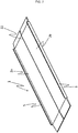
- Fig. 1 is a perspective view of a portable slope (which may be called “slope”, hereinafter) viewed from the top side.
- slope which may be called “slope”, hereinafter
- Symbol 1 indicates a portable slope while symbol 2 indicates a plate member constituting a slope part on which wheelchairs or the like run.
- Portable slope 1 may be bridged between a train door and a platform.
- upper end 3 of slope 1 is placed at the train door side while lower end 4 of slope 1 is placed at the platform side.
- upper end 3 and lower end 4 of slope 1 are formed in a tapered shape so that a predetermined inclination to make wheelchairs easily get on and off.
- an antislip rubber member is adhered to a contact position of slope 1 between a door and/or a platform.
- upper end 3 and lower end of slope 1 are made of a plastic, because it is light and cheap.
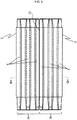
- Fig. 2 is a bottom side perspective view of our portable slope while Fig. 3 is a bottom view of our portable slope.
- Symbol 5 indicates a derailment prevention wall while symbol 6 indicates a first reinforcing part.
- First reinforcing part 6 is provided in a long continuous form, almost in parallel with the longitudinal direction of plate member 2 which direction is also a running direction of movable body such as wheelchair. Even when a local load is applied from tires of wheelchair or the like moving on slope 1, such a long continuous structure between upper end 3 and lower end 4 can endure the local load.
- Fig. 4 is an A-A cross section view of slope 1 shown in Fig. 3 .
- Fig. 4 shows a wheelchair or the like moving on a top face of plate member 2.
- Symbols 6a, 6b and 6d indicates first reinforcing parts
- symbol 7 indicates a hollow part formed between a plate and the first reinforcing part
- symbol 5 indicates a derailment prevention wall.
- First reinforcing part 6 is provided as bonded to one side of plate member 2 and hollow part 7 is formed between plate member 2 and first reinforcing part 6.
- a quadrangular cross section thereof can have a high load bearing characteristics for locally concentrated load.
- the quadrangular cross section shape is trapezoid with basic angles to contact the plate member of first reinforcing part, wherein at least one of the basic angles is 30 to 90° with respect to the horizontal direction of plate member surface.
- First reinforcing part 6 formed in a trapezoid shape having a predetermined basic angle is advantageous to improve the load bearing characteristics for load applied to a movable body moving on plate member 2.
- the basic angle of less than 30° might make the length perpendicular to the plate member of first reinforcing part so that sufficient rigidity cannot be achieved.
- the basic angle of more than 90° might weaken the load bearing characteristics.
- symbol ⁇ indicates the basic angle of first reinforcing part 6b as a representative example.
- the trapezoid shape is a kind of quadrangular which has at least one set of opposite sides in parallel to each other. It is preferable that the trapezoid shape is a normal trapezoid having a lower base to contact plate member 2 which is longer than an upper base although it should be noted Fig. 4 is illustrated upside down. From a viewpoint of good load bearing characteristics, the trapezoid shape having the lower base longer than the upper base is advantageous so that bending deformation of the plate member can be suppressed when a load is applied to the plate member to transmit the load to the first reinforcing part.
- first reinforcing part 6a has a trapezoid shape with the left basic angle of 60° and right basic angle of 60° while first reinforcing part 6b has a trapezoid shape with the right basic angle of 60° and left basic angle of 60°.
- Such symmetric basic angles of left and right first reinforcing parts 6a and 6b make the load application state balanced.
- first reinforcing part 6a has a trapezoid shape with the left basic angle of 30° and right basic angle of 60° while first reinforcing part 6b has a trapezoid shape with the right basic angle of 30° and left basic angle of 60°, such symmetric basic angles of first reinforcing parts 6a and 6b make the applied load balanced as well.
- Another first reinforcing part 6d will be explained later.
- one of the first reinforcing parts is isosceles trapezoid, so that a load is applied from the movable body moving on the top side of plate member 2 to the first reinforcing part uniformly to achieve higher load bearing characteristics. That is in a case that first reinforcing part 6a or 6b has a trapezoid shape with the left and right basic angles are the same in Fig. 4 .
- Fig. 5 shows another embodiment of layout of first reinforcing part 6.
- first reinforcing parts 6a, 6b, 6c and 6d are provided. It is preferable that first reinforcing part 6a is provided in the center in the width direction of plate member 2, that first reinforcing parts 6b and 6c are symmetrically disposed at a predetermined interval on both sides of first reinforcing part 6a, so that the load bearing characteristics with respect to the load applied when a movable body having a predetermined weight moves on the top side of plate 2 can be stronger.
- first reinforcing part 6a has a isosceles trapezoid shape with symmetrical left and right basic angles as explained for first reinforcing parts 6a and 6b in Fig. 4 . It is further preferable that all of first reinforcing part 6a, first reinforcing part 6b and first reinforcing part 6c are a isosceles trapezoid.
- one of the basic angles to contact the plate member of the first reinforcing part located at both ends of the plate member is right angle while the lateral surface of the right basic angle is located at the same side as a plate member lateral end surface. At least one first reinforcing part is located at both ends of plate member 2.
- the first reinforcing part one of which basic angles is right angle has many joining parts on derailment prevention wall 5 so that the joint strength to derailment prevention wall 5 can be enhanced.
- first reinforcing parts 6d are located at both ends.
- Base angle ⁇ 2 located outside the end part of plate 2 of first reinforcing part 6d is right angle.
- a lateral surface part is perpendicular to plate member 2 and is located at the same side as plate member 2 lateral end surface.
- Derailment prevention wall 5 is configured to join both the lateral end surface of plate member 2 and the lateral surface part of first reinforcing part 6d.
- slope 1 is provided with derailment prevention wall 5 located to be joined to at least a part of the plate member lateral end surface and the first reinforcing part lateral end surface. It is more preferable that the derailment prevention wall is located to be joined to a whole lateral surface part of the reinforcing part.
- Derailment prevention wall 5 provided at both left and right sides of slope 1 can prevent vehicles from dropping and the derailment prevention wall is hardly broken even if a wheel goes over derailment prevention wall 5, and the lightweight product can easily be carried.
- One of basic angles ⁇ 2 of first reinforcing part 6d corresponding to derailment prevention wall 5 is right angle while a lateral surface of which basic angle ⁇ 2 is right angle is located at the same side as a plate member lateral end surface, so that the derailment prevention wall can join the plate lateral end surface and the perpendicular surface of reinforcing part on the same surfaces. Therefore when derailment prevention wall 5 is joined to plate member 2 lateral end surface and first reinforcing part 6d lateral surface part 6d, impact durability can be enhanced with deformation and breakage of derailment prevention wall 5 by joining derailment prevention wall 5 to plate member 2 and first reinforcing part 6d.
- derailment prevention wall 5 has a protrusion height of 15 to 30mm from the top side of plate member 2. Derailment prevention wall 5 is not required to be formed all over the length of slope 1, so that it may not be formed at upper end side 3 and lower end side 4.
- the right angle reserves an allowable range of ⁇ 5° from viewpoints of design and production freedom.
- At least one of tangent angles at the tangent point to the plate member of the first reinforcing part is 30 to 90°. It is more preferable that the tangent angle is 35 to 80°, preferably 45 to 60°.
- the tangent angle at the tangent point to the plate member of the first reinforcing part is set within a predetermined range, so that the load bearing characteristics to the load applied when a movable body moves on plate member 2 is improved.
- the tangent angle of less than 30° might shorten the length perpendicular to the plate member of the first reinforcing part so that required rigidity cannot be achieved.
- the tangent angle of more than 90° might weaken the load durability characteristics.
- a tangent angle at a tangent point to the plate member of the first reinforcing part 6d located at both ends of the plate member and another tangent angle at another tangent point to derailment prevention wall 5 are right angles, so that the joint strength of derailment prevention wall 5 can be enhanced.
- the right angle reserves an allowable range of ⁇ 5° from viewpoints of design and production freedom.
- the second reinforcing part is formed to be inserted into a hollow part between the plate member and the first reinforcing part.
- an elastic member having a predetermined elastic strength may further be provided, so that the load bearing characteristics and usage stability can be improved.
- Fig. 6 is a cross section view showing a state in which a second reinforcing part is inserted into a hollow part formed between a plate member and a first reinforcing part.
- first reinforcing part 6b will be explained.
- Symbol 13 indicates an insertion slot having a predetermined insertion hole and a predetermined length and being provided for the second reinforcing part to be inserted inside hollow part 7 formed between plate member 2 and the first reinforcing part.
- Second reinforcing part 14 comprising a long elastic body having a predetermined length is inserted into the inside of insertion slot 13. Because slope 1 is often used as inclined, second reinforcing part 14 is fixed enough not to move inside insertion slot 13.
- the first reinforcing part and the second reinforcing part are made of fiber-reinforced plastic.
- the fiber-reinforced plastic is a carbon fiber-reinforced plastic made from a carbon fiber, such as PAN-based, pitch-based and rayon-based carbon fiber, excellent in specific strength and specific rigidity.
- the fiber-reinforced plastic is made from a thermosetting resin such as unsaturated polyester resin, vinyl ester resin, epoxy resin, phenol (resol type) resin and polyimide resin.
- a thermosetting resin such as unsaturated polyester resin, vinyl ester resin, epoxy resin, phenol (resol type) resin and polyimide resin.
- the epoxy resin from viewpoints of dynamics properties and heat resistance of formed product.
- the fiber-reinforced resin comprises carbon fibers of 15 to 80 wt% as fiber weight content.
- the content of less than 15wt% might not achieve the load bearing characteristics and rigidity enough to function desirably.
- the content of more than 80% might generate voids in the fiber-reinforced resin to make it difficult to form a product.
- first reinforcing part and the second reinforcing part is formed with the fiber-reinforced plastic comprising continuous carbon fibers.
- Reinforcing fibers may be aligned in parallel with the longitudinal direction in which the slope is bridged, or aligned almost perpendicular to the longitudinal. The combination of these alignments can improve bending strength and surface pressure resistance as a whole slope.
- the slope comprises two or more plate members connected to each other so that plate members (such as plate members A and B) each having at least the first reinforcing part of which surfaces can be folded as opposing to each other from a viewpoint of portability.
- Fig. 7 is a perspective view showing a state viewed from the top side, in which plate members (such as plate members A and B) are arranged in parallel with respect to the running direction and are connected with opposing lateral surfaces of the plate member by sheet member or hinge.
- Symbol 22 indicates a connected part connected by the sheet member or hinge.
- Symbols 2a and 2b indicate plate member A and plate member B in the Fig.
- Fig. 8 is a bottom view showing a state in which plate members are arranged in parallel with respect to the longitudinal direction and are connected with opposing lateral surfaces of the plate member by sheet member.
- Two plate members 2a and 2b are provided as foldable.
- Plate member 2a is provided with three first reinforcing parts 6 while plate member 2b is provided with three first reinforcing parts 6.
- Fig. 9 is a B-B cross section view in Fig. 8 .
- Plate member 2a is provided with first reinforcing parts 6e, 6f and 6g.
- plate member 2b is provided with first reinforcing parts 6e, 6f and 6g.
- Derailment prevention wall 5 is configured to be provided on the lateral surface part of first reinforcing part 6e of plate member 2a as well as the lateral surface part of second reinforcing part 6e of plate member 2b.
- Fig. 10 is a cross section view corresponding to Fig. 9 showing a state in which the second reinforcing part is inserted.
- first reinforcing part 6f will be explained.
- Insertion slot 13 having a predetermined insertion hole and a predetermined length is provided for second reinforcing part 14 to be inserted inside hollow part 7 formed between plate member 2a and first reinforcing part 6f.
- a derailment prevention wall is provided on a plate member lateral end surface located at both sides of slope comprising a plate member provided with a first reinforcing part.
- the derailment prevention wall may be provided thereon by such a method that the plate member, first reinforcing part and derailment prevention wall are formed integrally, and that the derailment prevention wall is bonded to the plate member lateral end surface and the reinforcing part lateral surface after forming the plate member and first reinforcing part integrally.
- the first reinforcing part and the derailment prevention wall are formed integrally. With such a configuration, a process to install the derailment prevention wall is not necessary and therefore production cost can be reduced.
- the derailment prevention wall becomes hard to break because the plate member, the first reinforcing part and the derailment prevention wall have been formed integrally. It is also preferable that the plate member, the first reinforcing part, the insertion slot of the second reinforcing part and the derailment prevention wall are formed integrally.
- Our invention provides a portable slope to be used to bridge a difference in step produced between things.
Landscapes
- Engineering & Computer Science (AREA)
- Public Health (AREA)
- Health & Medical Sciences (AREA)
- Architecture (AREA)
- Animal Behavior & Ethology (AREA)
- Veterinary Medicine (AREA)
- General Health & Medical Sciences (AREA)
- Life Sciences & Earth Sciences (AREA)
- Mechanical Engineering (AREA)
- Civil Engineering (AREA)
- Structural Engineering (AREA)
- Steps, Ramps, And Handrails (AREA)
- Vehicle Step Arrangements And Article Storage (AREA)
- Handcart (AREA)
Abstract
Description
- Our invention relates to a slope to be used to bridge a difference in step produced between things, the slope being lightweight and exhibiting excellent load resistance and durability, making it possible for a wheelchair-user to safely get on and off a train with the slope, and further exhibiting excellent portability.
- Recently, public institutions are provided with elevators and escalators as barrier-free measures. A detour slope may be installed beside stairs so that a wheelchair can easily go through. However, many steps still exist inside and outside of the buildings such as public institutions. Although such steps can easily be cleared by a healthy person, a wheelchair user and an old person may have some difficulty of getting over them.
- Even if they proceed with infrastructure construction for barrier-free society, there exist many steps left, such as steps between sidewalk and street, steps between bus door and road, ditches on the street, steps and ditches between train door and platform, obstructing wheelchairs passing.
- Such many steps exist even inside and outside personal residences where wheelchair users and elder people live, as well as in a public space and transportation facilities.
- Recently, a portable slope may be used as a bridging plate set from a platform into a train or another bridging plate set from a road into a bus as needed when a wheelchair is rolled from a platform into a train or from a train door to the platform, or when a wheel chair is rolled from a road into a bus or from a bus door to the road.
- These slopes should be lightweight enough to be carried easily, so that they are preferably made of resin, which is specifically fiber-reinforced plastic being lightweight and excellent in load bearing characteristics disclosed in
Patent documents - A slope for wheelchairs, being an implement on which a wheelchair with a person in need of nursing care is rolled forward and backward by an assistant, should be prevented from damaging with insufficient strength and falling from the wheelchair because of derailing. For example, a derailment prevention wall may be provided on an edge part of the slopes in a wheelchair rollup direction. The impact durability of the derailment prevention wall is important because it might be hit by a wheelchair wrongly controlled by an assistant. It is also important that a slope edge part which might be hit during carriage and the corresponding derailment prevention wall have a good impact durability.
- Patent document 1 (
JP2011-217963-A - However,
Patent document 1 only refers to the slope made of fiber-reinforced resin but fails to suggest any simultaneous pursuit of weight saving and load bearing characteristics. Also, a normal plate may not achieve sufficient load bearing characteristics because load tends to concentrate to tires of wheelchair or the like rolling on the slope. In addition, it doesn't refer to any improvement of impact durability of the short height protection wall part provided at both edges in the width direction of the slope main body to prevent wheelchairs from derailing out of it. - Patent document 2 (
JP2013-162818-A sheet material 6 so that the plyboards can be folded on top of each other, wherein the plyboards comprising Fiber-Reinforced Plastic (FRP) plate members bonded to both top and bottom sides of a quadrel core member made of foamable resin hastapered structures - However, production cost might be expensive with many processes to produce a laminate body disclosed in
Patent document 2 since it discloses a plyboard having a laminated structure of carbon fiber-reinforced plastic strongly bonded to both top and bottom sides of foamable resin. Also, a normal plate may not achieve sufficient load bearing characteristics because load tends to concentrate to tires of wheelchair or the like rolling on the slope even though rigidity may be improved by the laminate structure. In addition, the derailment prevention wall provided at both lateral surfaces might be insufficiently bonded to both sides of plyboards because of little thickness of plyboards contributing the integrated bonding of the plate member and derailment prevention wall. - Patent document 3 (
JP2003-230600-A Patent document 3 discloses a preferable method of forming a plate member and derailment prevention walls integrally to make the derailment prevention wall hard to break in a configuration such that after reinforcing fibers are wound on a core member made of hard foaming polyurethane or the like and then are placed in a die, matrix agent is poured into the die to form the plate member and derailment prevention walls integrally. - However, the derailment prevention wall disclosed in
Patent document 3 might be insufficiently bonded because of little thickness of plate member contributing the integrated bonding of the plate member and derailment prevention wall. - Patent document 4 (
JP2014-103983-A - However, production cost might be expensive with many processes to produce a laminate body disclosed in
Patent document 4 since it discloses a slope main body comprising a plate-shaped core made of cardboard and a reinforcing layer made of fiber-reinforced resin member pasted on top and bottom sides. Also, a normal plate may not achieve sufficient load bearing characteristics because load tends to concentrate to tires of wheelchair or the like rolling on the slope even though weight saving may be possible. In addition, the derailment prevention wall provided at both lateral surfaces might be insufficiently bonded to both sides of plate-shaped core made of cardboard because of little thickness of plyboards contributing the integrated bonding of the plate member and derailment prevention wall. -
- Patent document 1:
JP2011-217963-A - Patent document 2:
JP2013-162818-A - Patent document 3:
JP2003-230600-A - Patent document 4:
JP2014-103983-A - According to such problems of background art, it could be helpful to provide a portable slope used to bridge a difference in step produced between things, the slope being lightweight and exhibiting excellent load resistance and durability, maintaining the rigidity even when loaded on the slope by a wheelchair-user, and further exhibiting excellent portability of the slope itself.
-
- (1) A potable slope comprising at least a plate member and a first reinforcing part which is provided as extending along a longitudinal direction of the slope, wherein a hollow part is formed between the plate member and the first reinforcing part.
- (2) The portable slope according to (1), wherein the first reinforcing part has a quadrangular cross section which is perpendicular to the longitudinal direction.
- (3) The portable slope according to (2), wherein the first reinforcing part has a trapezoid cross section perpendicular to the longitudinal direction, the trapezoid having at least one basic angle of 30 to 90° to contact the plate member.
- (4) The portable slope according to (3), wherein the first reinforcing part has at least one isosceles trapezoid cross section perpendicular to the longitudinal direction.
- (5) The portable slope according to (3) or (4), wherein the basic angle located at a plate member lateral part is right angle.
- (6) The portable slope according to any one of (1) to (5), further comprising a second reinforcing part.
- (7) The portable slope according to (6), wherein the second reinforcing part is formed to be inserted into the hollow part between the plate member and the first reinforcing part.
- (8) The portable slope according to (6) or (7), wherein the plate member, the first reinforcing part and the second reinforcing part are made of a fiber-reinforced plastic.
- (9) The portable slope according to any one of (1) to (8), wherein the derailment prevention wall is provided to be joined to at least a part of the plate member lateral end surface and the first reinforcing part lateral end surface.
- (10) The portable slope according to (9), wherein the derailment prevention wall is provided to be joined to a whole of the lateral end surface of the plate member and the lateral end surface of the first reinforcing part.
- (11) The portable slope according to (9) or (10), wherein the plate member, the first reinforcing part and the derailment prevention wall are formed integrally.
- The above-described portable slope, which is used to bridge a difference in step produced between things, the slope being lightweight and exhibiting excellent load bearing characteristics and durability, makes it possible for a wheelchair-user to safely get on and off a train with the slope, as exhibiting excellent portability.
-
- [
Fig. 1] Fig. 1 is a top side perspective view showing a portable slope according to an example of our invention. - [
Fig. 2] Fig. 2 is a bottom side perspective view showing a portable slope according to an example of our invention. - [
Fig. 3] Fig. 3 is a bottom view showing a portable slope according to an example of our invention. - [
Fig. 4] Fig. 4 is an A-A cross section view ofslope 1 shown inFig. 3 . - [
Fig. 5] Fig. 5 is an A-A cross section view ofslope 1 shown inFig. 3 with another first reinforcing part configuration. - [
Fig. 6] Fig. 6 is a cross section view showing a state in which a second reinforcing part is inserted into a hollow part formed between a plate member and a first reinforcing part. - [
Fig. 7] Fig. 7 is a top side perspective view showing a state in which plate members are arranged in parallel with respect to the longitudinal direction and are connected with opposing lateral surfaces of the plate member. - [
Fig. 8] Fig. 8 is a bottom view showing a state in which plate members are arranged in parallel with respect to the longitudinal direction and are connected with opposing lateral surfaces of the plate member. - [
Fig. 9] Fig. 9 is a B-B cross section view inFig. 8 . - [
Fig. 10] Fig. 10 is a cross section view corresponding toFig. 9 showing a state in which a second reinforcing part is inserted into a hollow part formed between a plate member and a first reinforcing part. - Hereinafter, our invention will be explained with reference to the figures. Our invention is not limited specifically with the figures.
- To solve the above-described problem, our invention has a configuration of a potable slope comprising at least a plate member and a first reinforcing part which is provided along a longitudinal direction of the slope, wherein a hollow part is formed between the plate member and the first reinforcing part.
- With such a basic configuration of our slope comprising at least a plate member and a first reinforcing part which is provided along a longitudinal direction of the slope wherein a hollow part is formed between the plate member and the first reinforcing part, it is possible to achieve weight saving and rigidity securement of the portable slope to be used for wheelchair users to go over a step which exists in a building or is produced between the ground and a door of car, train, bus or the like. The first reinforcing part is provided at the bottom side opposite to a plate member surface on which a movable body such as wheelchair runs, so that the rigidity of the slope itself can be enhanced without interfering with running of wheelchair or the like.
- It is preferable that the first reinforcing part has a quadrangular cross section which is perpendicular to the longitudinal direction. Although load is locally concentrated to tires of wheelchair or the like moving on the slope, our configuration can achieve safe conveyance with good load bearing characteristics of the first reinforcing part.
-
Fig. 1 is a perspective view of a portable slope (which may be called "slope", hereinafter) viewed from the top side. -
Symbol 1 indicates a portable slope whilesymbol 2 indicates a plate member constituting a slope part on which wheelchairs or the like run.Portable slope 1 may be bridged between a train door and a platform. For example,upper end 3 ofslope 1 is placed at the train door side whilelower end 4 ofslope 1 is placed at the platform side. It is preferable thatupper end 3 andlower end 4 ofslope 1 are formed in a tapered shape so that a predetermined inclination to make wheelchairs easily get on and off. It is also preferable an antislip rubber member is adhered to a contact position ofslope 1 between a door and/or a platform. It is preferable thatupper end 3 and lower end ofslope 1 are made of a plastic, because it is light and cheap. -
Fig. 2 is a bottom side perspective view of our portable slope whileFig. 3 is a bottom view of our portable slope.Symbol 5 indicates a derailment prevention wall whilesymbol 6 indicates a first reinforcing part. First reinforcingpart 6 is provided in a long continuous form, almost in parallel with the longitudinal direction ofplate member 2 which direction is also a running direction of movable body such as wheelchair. Even when a local load is applied from tires of wheelchair or the like moving onslope 1, such a long continuous structure betweenupper end 3 andlower end 4 can endure the local load. -
Fig. 4 is an A-A cross section view ofslope 1 shown inFig. 3 .Fig. 4 shows a wheelchair or the like moving on a top face ofplate member 2.Symbols symbol 5 indicates a derailment prevention wall. - The shape of first reinforcing
part 6 will be explained. First reinforcingpart 6 is provided as bonded to one side ofplate member 2 and hollow part 7 is formed betweenplate member 2 and first reinforcingpart 6. A quadrangular cross section thereof can have a high load bearing characteristics for locally concentrated load. - It is more preferable that the quadrangular cross section shape is trapezoid with basic angles to contact the plate member of first reinforcing part, wherein at least one of the basic angles is 30 to 90° with respect to the horizontal direction of plate member surface.
- First reinforcing
part 6 formed in a trapezoid shape having a predetermined basic angle is advantageous to improve the load bearing characteristics for load applied to a movable body moving onplate member 2. The basic angle of less than 30° might make the length perpendicular to the plate member of first reinforcing part so that sufficient rigidity cannot be achieved. The basic angle of more than 90° might weaken the load bearing characteristics. InFig. 4 , symbol θ indicates the basic angle of first reinforcingpart 6b as a representative example. - The trapezoid shape is a kind of quadrangular which has at least one set of opposite sides in parallel to each other. It is preferable that the trapezoid shape is a normal trapezoid having a lower base to contact
plate member 2 which is longer than an upper base although it should be notedFig. 4 is illustrated upside down. From a viewpoint of good load bearing characteristics, the trapezoid shape having the lower base longer than the upper base is advantageous so that bending deformation of the plate member can be suppressed when a load is applied to the plate member to transmit the load to the first reinforcing part. - In an embodiment shown in
Fig. 4 , first reinforcingpart 6a has a trapezoid shape with the left basic angle of 60° and right basic angle of 60° while first reinforcingpart 6b has a trapezoid shape with the right basic angle of 60° and left basic angle of 60°. Such symmetric basic angles of left and right first reinforcingparts part 6a has a trapezoid shape with the left basic angle of 30° and right basic angle of 60° while first reinforcingpart 6b has a trapezoid shape with the right basic angle of 30° and left basic angle of 60°, such symmetric basic angles of first reinforcingparts part 6d will be explained later. - It is preferable that one of the first reinforcing parts is isosceles trapezoid, so that a load is applied from the movable body moving on the top side of
plate member 2 to the first reinforcing part uniformly to achieve higher load bearing characteristics. That is in a case that first reinforcingpart Fig. 4 . -
Fig. 5 shows another embodiment of layout of first reinforcingpart 6. In such a configuration, an odd number of first reinforcingparts 6 are provided. Specifically, first reinforcingparts part 6a is provided in the center in the width direction ofplate member 2, that first reinforcingparts 6b and 6c are symmetrically disposed at a predetermined interval on both sides of first reinforcingpart 6a, so that the load bearing characteristics with respect to the load applied when a movable body having a predetermined weight moves on the top side ofplate 2 can be stronger. It is more preferable that first reinforcingpart 6a has a isosceles trapezoid shape with symmetrical left and right basic angles as explained for first reinforcingparts Fig. 4 . It is further preferable that all of first reinforcingpart 6a, first reinforcingpart 6b and first reinforcing part 6c are a isosceles trapezoid. - It is preferable that one of the basic angles to contact the plate member of the first reinforcing part located at both ends of the plate member is right angle while the lateral surface of the right basic angle is located at the same side as a plate member lateral end surface. At least one first reinforcing part is located at both ends of
plate member 2. - The first reinforcing part one of which basic angles is right angle has many joining parts on
derailment prevention wall 5 so that the joint strength toderailment prevention wall 5 can be enhanced. - In s cross section views shown in
Fig. 4 andFig. 5 , first reinforcingparts 6d are located at both ends. Base angle θ2 located outside the end part ofplate 2 of first reinforcingpart 6d is right angle. Namely, a lateral surface part is perpendicular toplate member 2 and is located at the same side asplate member 2 lateral end surface.Derailment prevention wall 5 is configured to join both the lateral end surface ofplate member 2 and the lateral surface part of first reinforcingpart 6d. - It is preferable that
slope 1 is provided withderailment prevention wall 5 located to be joined to at least a part of the plate member lateral end surface and the first reinforcing part lateral end surface. It is more preferable that the derailment prevention wall is located to be joined to a whole lateral surface part of the reinforcing part. -
Derailment prevention wall 5 provided at both left and right sides ofslope 1 can prevent vehicles from dropping and the derailment prevention wall is hardly broken even if a wheel goes overderailment prevention wall 5, and the lightweight product can easily be carried. - One of basic angles θ2 of first reinforcing
part 6d corresponding toderailment prevention wall 5 is right angle while a lateral surface of which basic angle θ2 is right angle is located at the same side as a plate member lateral end surface, so that the derailment prevention wall can join the plate lateral end surface and the perpendicular surface of reinforcing part on the same surfaces. Therefore whenderailment prevention wall 5 is joined toplate member 2 lateral end surface and first reinforcingpart 6dlateral surface part 6d, impact durability can be enhanced with deformation and breakage ofderailment prevention wall 5 by joiningderailment prevention wall 5 toplate member 2 and first reinforcingpart 6d. - It is preferable that
derailment prevention wall 5 has a protrusion height of 15 to 30mm from the top side ofplate member 2.Derailment prevention wall 5 is not required to be formed all over the length ofslope 1, so that it may not be formed atupper end side 3 andlower end side 4. The right angle reserves an allowable range of ±5° from viewpoints of design and production freedom. - It is preferable that at least one of tangent angles at the tangent point to the plate member of the first reinforcing part is 30 to 90°. It is more preferable that the tangent angle is 35 to 80°, preferably 45 to 60°.
- The tangent angle at the tangent point to the plate member of the first reinforcing part is set within a predetermined range, so that the load bearing characteristics to the load applied when a movable body moves on
plate member 2 is improved. The tangent angle of less than 30° might shorten the length perpendicular to the plate member of the first reinforcing part so that required rigidity cannot be achieved. The tangent angle of more than 90° might weaken the load durability characteristics. - It is preferable that a tangent angle at a tangent point to the plate member of the first reinforcing
part 6d located at both ends of the plate member and another tangent angle at another tangent point toderailment prevention wall 5 are right angles, so that the joint strength ofderailment prevention wall 5 can be enhanced. The right angle reserves an allowable range of ±5° from viewpoints of design and production freedom. - It is preferable to further provide a second reinforcing part.
- It is preferable that the second reinforcing part is formed to be inserted into a hollow part between the plate member and the first reinforcing part.
- Assuming a case that a movable body to which heavier load is applied moves, if the weight is forecasted, an elastic member having a predetermined elastic strength may further be provided, so that the load bearing characteristics and usage stability can be improved.
-
Fig. 6 is a cross section view showing a state in which a second reinforcing part is inserted into a hollow part formed between a plate member and a first reinforcing part. For example, first reinforcingpart 6b will be explained.Symbol 13 indicates an insertion slot having a predetermined insertion hole and a predetermined length and being provided for the second reinforcing part to be inserted inside hollow part 7 formed betweenplate member 2 and the first reinforcing part. Second reinforcingpart 14 comprising a long elastic body having a predetermined length is inserted into the inside ofinsertion slot 13. Becauseslope 1 is often used as inclined, second reinforcingpart 14 is fixed enough not to move insideinsertion slot 13. - It is preferable that the first reinforcing part and the second reinforcing part are made of fiber-reinforced plastic. From a viewpoint of weight saving effect, it is preferable that the fiber-reinforced plastic is a carbon fiber-reinforced plastic made from a carbon fiber, such as PAN-based, pitch-based and rayon-based carbon fiber, excellent in specific strength and specific rigidity.
- It is preferable that the fiber-reinforced plastic is made from a thermosetting resin such as unsaturated polyester resin, vinyl ester resin, epoxy resin, phenol (resol type) resin and polyimide resin. Above all, it is preferable to employ the epoxy resin from viewpoints of dynamics properties and heat resistance of formed product.
- It is preferable that the fiber-reinforced resin comprises carbon fibers of 15 to 80 wt% as fiber weight content. The content of less than 15wt% might not achieve the load bearing characteristics and rigidity enough to function desirably. The content of more than 80% might generate voids in the fiber-reinforced resin to make it difficult to form a product.
- It is preferable that the first reinforcing part and the second reinforcing part is formed with the fiber-reinforced plastic comprising continuous carbon fibers.
- Reinforcing fibers may be aligned in parallel with the longitudinal direction in which the slope is bridged, or aligned almost perpendicular to the longitudinal. The combination of these alignments can improve bending strength and surface pressure resistance as a whole slope.
- Hereinbefore, a slope consisting of one plate member has been explained. Alternatively, it is preferable that the slope comprises two or more plate members connected to each other so that plate members (such as plate members A and B) each having at least the first reinforcing part of which surfaces can be folded as opposing to each other from a viewpoint of portability.
-
Fig. 7 is a perspective view showing a state viewed from the top side, in which plate members (such as plate members A and B) are arranged in parallel with respect to the running direction and are connected with opposing lateral surfaces of the plate member by sheet member or hinge.Symbol 22 indicates a connected part connected by the sheet member or hinge.Symbols -
Fig. 8 is a bottom view showing a state in which plate members are arranged in parallel with respect to the longitudinal direction and are connected with opposing lateral surfaces of the plate member by sheet member. Twoplate members Plate member 2a is provided with three first reinforcingparts 6 whileplate member 2b is provided with three first reinforcingparts 6. -
Fig. 9 is a B-B cross section view inFig. 8 .Plate member 2a is provided with first reinforcingparts plate member 2b is provided with first reinforcingparts Derailment prevention wall 5 is configured to be provided on the lateral surface part of first reinforcingpart 6e ofplate member 2a as well as the lateral surface part of second reinforcingpart 6e ofplate member 2b. -
Fig. 10 is a cross section view corresponding toFig. 9 showing a state in which the second reinforcing part is inserted. For example, first reinforcingpart 6f will be explained.Insertion slot 13 having a predetermined insertion hole and a predetermined length is provided for second reinforcingpart 14 to be inserted inside hollow part 7 formed betweenplate member 2a and first reinforcingpart 6f. - A derailment prevention wall is provided on a plate member lateral end surface located at both sides of slope comprising a plate member provided with a first reinforcing part. The derailment prevention wall may be provided thereon by such a method that the plate member, first reinforcing part and derailment prevention wall are formed integrally, and that the derailment prevention wall is bonded to the plate member lateral end surface and the reinforcing part lateral surface after forming the plate member and first reinforcing part integrally. Above all, it is preferable that the first reinforcing part and the derailment prevention wall are formed integrally. With such a configuration, a process to install the derailment prevention wall is not necessary and therefore production cost can be reduced. Further, the derailment prevention wall becomes hard to break because the plate member, the first reinforcing part and the derailment prevention wall have been formed integrally. It is also preferable that the plate member, the first reinforcing part, the insertion slot of the second reinforcing part and the derailment prevention wall are formed integrally.
- Our invention provides a portable slope to be used to bridge a difference in step produced between things.
-
- 1:
- slope
- 2, 2a, 2b:
- plate member
- 3:
- upper end of slope
- 4:
- lower end of
slope 1 - 5:
- derailment prevention wall
- 6, 6a, 6b, 6c, 6d, 6f, 6g:
- first reinforcing part
- 7:
- hollow part formed between plate and first reinforcing part
- 13:
- insertion slot of second reinforcing part
- 14:
- second reinforcing part
- 15:
- lateral width length of plate member
- 16:
- lower base length of first reinforcing
part 6d - 17:
- lower base length of first reinforcing
part 6b - 18:
- lower base length of first reinforcing
part 6a - 19:
- lower base length of first reinforcing part 6c
- 20:
- lower base length of first reinforcing
part 6d - 21:
- height of first reinforcing
part 6b from the top side of plate member - 22:
- connected part
Claims (11)
- A potable slope comprising at least a plate member and a first reinforcing part which is provided as extending along a longitudinal direction of the slope, wherein a hollow part is formed between the plate member and the first reinforcing part.
- The portable slope according to claim 1, wherein the first reinforcing part has a quadrangular cross section which is perpendicular to the longitudinal direction.
- The portable slope according to claim 2, wherein the first reinforcing part has a trapezoid cross section perpendicular to the longitudinal direction, the trapezoid having at least one basic angle of 30 to 90° to contact the plate member.
- The portable slope according to claim 3, wherein the first reinforcing part has at least one isosceles trapezoid cross section perpendicular to the longitudinal direction.
- The portable slope according to claim 3 or 4, wherein the basic angle located at a plate member lateral part is right angle.
- The portable slope according to any one of claims 1 to 5, further comprising a second reinforcing part.
- The portable slope according to claim 6, wherein the second reinforcing part is formed to be inserted into the hollow part between the plate member and the first reinforcing part.
- The portable slope according to claim 6 or 7, wherein the plate member, the first reinforcing part and the second reinforcing part are made of a fiber-reinforced plastic.
- The portable slope according to any one of claims 1 to 8, wherein the derailment prevention wall is provided to be joined to at least a part of the plate member lateral end surface and the first reinforcing part lateral end surface.
- The portable slope according to claim 9, wherein the derailment prevention wall is provided to be joined to a whole of the lateral end surface of the plate member and the lateral end surface of the first reinforcing part.
- The portable slope according to claim 9 or 10, wherein the plate member, the first reinforcing part and the derailment prevention wall are formed integrally.
Applications Claiming Priority (2)
| Application Number | Priority Date | Filing Date | Title |
|---|---|---|---|
| JP2014198662A JP2016067517A (en) | 2014-09-29 | 2014-09-29 | Portable slope |
| PCT/JP2015/072756 WO2016051966A1 (en) | 2014-09-29 | 2015-08-11 | Portable slope |
Publications (2)
| Publication Number | Publication Date |
|---|---|
| EP3202385A1 true EP3202385A1 (en) | 2017-08-09 |
| EP3202385A4 EP3202385A4 (en) | 2018-05-23 |
Family
ID=55630012
Family Applications (1)
| Application Number | Title | Priority Date | Filing Date |
|---|---|---|---|
| EP15846082.4A Withdrawn EP3202385A4 (en) | 2014-09-29 | 2015-08-11 | Portable slope |
Country Status (7)
| Country | Link |
|---|---|
| US (1) | US20170275886A1 (en) |
| EP (1) | EP3202385A4 (en) |
| JP (1) | JP2016067517A (en) |
| KR (1) | KR20170066437A (en) |
| CN (1) | CN106714759A (en) |
| TW (1) | TW201620474A (en) |
| WO (1) | WO2016051966A1 (en) |
Families Citing this family (17)
| Publication number | Priority date | Publication date | Assignee | Title |
|---|---|---|---|---|
| JP6535841B2 (en) * | 2017-03-30 | 2019-07-03 | 株式会社 ダイサン | Baggage loading board |
| US20190150400A1 (en) * | 2017-11-19 | 2019-05-23 | Sudesh Kumar | Sliding and stacking portable ramp |
| CN109625817B (en) * | 2018-12-28 | 2020-11-20 | 福州市长乐区炜辉工业设计有限公司 | Station baggage transfer desk |
| USD910938S1 (en) * | 2019-03-26 | 2021-02-16 | Vermont Juvenile Furniture Mfg., Inc. | Pet ramp |
| CN113492887B (en) * | 2020-04-02 | 2023-01-24 | 中车唐山机车车辆有限公司 | Movable ramp device for railway vehicle and railway vehicle |
| JP7518670B2 (en) * | 2020-06-12 | 2024-07-18 | 宇部エクシモ株式会社 | Fiber-reinforced hollow structure and manufacturing method thereof |
| EP4173608A4 (en) * | 2020-06-24 | 2024-07-17 | Sumitomo Rubber Industries, Ltd. | RAMP |
| CN115361929A (en) * | 2020-06-24 | 2022-11-18 | 住友橡胶工业株式会社 | Walking aid for wheelchair |
| US12162703B2 (en) * | 2020-07-16 | 2024-12-10 | Motis, Llc | Combination ramp and load levelers |
| US12415690B2 (en) | 2020-07-16 | 2025-09-16 | Motis, Llc | Trussed ramp |
| CN112660858B (en) * | 2020-12-08 | 2022-07-08 | 中山市科力高自动化设备有限公司 | a transitional agency |
| USD987916S1 (en) * | 2021-07-14 | 2023-05-30 | Hefei Haimai Information Technology Co., Ltd. | Pet climbing platform |
| USD995955S1 (en) * | 2021-10-20 | 2023-08-15 | Ningbo Seedling Industry and Technology Pte. Ltd. | Animal saving escape ramp |
| USD1066741S1 (en) * | 2022-01-24 | 2025-03-11 | Worxsafe Ab | Temporary bridge |
| USD1013984S1 (en) * | 2022-05-30 | 2024-02-06 | Xiyong Han | Pet ramp |
| USD1062139S1 (en) * | 2023-07-20 | 2025-02-11 | Worxsafe Ab | Bridge |
| USD1073243S1 (en) * | 2023-07-20 | 2025-04-29 | Worxsafe Ab | Bridge |
Family Cites Families (15)
| Publication number | Priority date | Publication date | Assignee | Title |
|---|---|---|---|---|
| US3184773A (en) * | 1961-09-07 | 1965-05-25 | Woodford Mfg Company | Dock plate |
| JP2573074Y2 (en) * | 1992-03-04 | 1998-05-28 | 岡部株式会社 | Temporary sidewalk |
| WO1994005878A1 (en) * | 1992-08-27 | 1994-03-17 | Designatech Services Pty. Ltd. | Transportable ramp |
| DE9301787U1 (en) * | 1993-02-04 | 1993-04-01 | Koch, Christian, 2090 Winsen | Crossing bridge |
| US5781953A (en) * | 1996-07-22 | 1998-07-21 | Overhead Door Corporation | Dock leveler ramp |
| US5913340A (en) * | 1997-09-15 | 1999-06-22 | Composite Structures, Inc. | Walkway platform |
| US5938397A (en) * | 1999-01-29 | 1999-08-17 | Schouest; Paul Daryl | Loading and unloading ramp for pickup trucks trailers and vans |
| JP2002306536A (en) * | 2001-04-10 | 2002-10-22 | Aisin Keikinzoku Co Ltd | Slope device for vehicle |
| JP2004142509A (en) * | 2002-10-22 | 2004-05-20 | Macgregor Kayaba Ltd | Hatch cover reinforcement method and reinforcement structure |
| JP4675211B2 (en) * | 2005-10-27 | 2011-04-20 | 住友ゴム工業株式会社 | Slope for getting on and off the train |
| JP5361636B2 (en) * | 2009-09-26 | 2013-12-04 | カネソウ株式会社 | Floor joint cover device |
| CN201677812U (en) * | 2010-02-01 | 2010-12-22 | 李云 | Folding type bridge deck |
| JP3172583U (en) * | 2011-07-13 | 2012-01-05 | 株式会社堀口工業所 | Super lightweight portable slope |
| JP2013106879A (en) * | 2011-11-24 | 2013-06-06 | Sumikei Techno Co Ltd | Slope |
| CN205134983U (en) * | 2015-11-26 | 2016-04-06 | 文登蓝岛建筑工程有限公司 | Construction stair tread |
-
2014
- 2014-09-29 JP JP2014198662A patent/JP2016067517A/en active Pending
-
2015
- 2015-08-11 CN CN201580052593.9A patent/CN106714759A/en active Pending
- 2015-08-11 KR KR1020177010214A patent/KR20170066437A/en not_active Withdrawn
- 2015-08-11 EP EP15846082.4A patent/EP3202385A4/en not_active Withdrawn
- 2015-08-11 US US15/510,906 patent/US20170275886A1/en not_active Abandoned
- 2015-08-11 WO PCT/JP2015/072756 patent/WO2016051966A1/en not_active Ceased
- 2015-09-18 TW TW104130879A patent/TW201620474A/en unknown
Also Published As
| Publication number | Publication date |
|---|---|
| WO2016051966A1 (en) | 2016-04-07 |
| TW201620474A (en) | 2016-06-16 |
| KR20170066437A (en) | 2017-06-14 |
| JP2016067517A (en) | 2016-05-09 |
| US20170275886A1 (en) | 2017-09-28 |
| EP3202385A4 (en) | 2018-05-23 |
| CN106714759A (en) | 2017-05-24 |
Similar Documents
| Publication | Publication Date | Title |
|---|---|---|
| US20170275886A1 (en) | Portable slope | |
| WO2021261299A1 (en) | Slope | |
| JP2016067517A5 (en) | ||
| JP7606968B2 (en) | Wheelchair mobility aids | |
| JP3171678U (en) | Transfer board | |
| US20170247227A1 (en) | A stairlift, for transporting a load along a staircase | |
| EP2484324A1 (en) | Slope device for wheelchair | |
| WO2018104501A1 (en) | Backbone rail for a roller coaster and roller coaster arrangement | |
| JP2010540377A5 (en) | ||
| JP2014124495A (en) | Portable slope | |
| CN202245629U (en) | rail transport device | |
| WO2016051967A1 (en) | Portable slope | |
| JP3172583U (en) | Super lightweight portable slope | |
| JP5969827B2 (en) | Transfer board | |
| JP6164896B2 (en) | Slope device | |
| CN104385869B (en) | A kind of side forklift and its suspension frame structure | |
| JP5969828B2 (en) | Transfer board | |
| CN204781873U (en) | A people's bank of china's packway for construction layer | |
| CN215854515U (en) | Turning track, turning linkage mechanism, stair climbing device and stair climbing system | |
| JP5087177B1 (en) | Portable slope device | |
| CN111747278B (en) | Extensible escalator pedal | |
| JP2014088703A (en) | Method for manufacturing bridge plate | |
| CN208167958U (en) | A kind of construction wall metope docking mechanism | |
| KR200161063Y1 (en) | Safety scaffolding | |
| JP2017133231A (en) | Slope material |
Legal Events
| Date | Code | Title | Description |
|---|---|---|---|
| PUAI | Public reference made under article 153(3) epc to a published international application that has entered the european phase |
Free format text: ORIGINAL CODE: 0009012 |
|
| 17P | Request for examination filed |
Effective date: 20170324 |
|
| AK | Designated contracting states |
Kind code of ref document: A1 Designated state(s): AL AT BE BG CH CY CZ DE DK EE ES FI FR GB GR HR HU IE IS IT LI LT LU LV MC MK MT NL NO PL PT RO RS SE SI SK SM TR |
|
| AX | Request for extension of the european patent |
Extension state: BA ME |
|
| DAV | Request for validation of the european patent (deleted) | ||
| DAX | Request for extension of the european patent (deleted) | ||
| A4 | Supplementary search report drawn up and despatched |
Effective date: 20180425 |
|
| RIC1 | Information provided on ipc code assigned before grant |
Ipc: A61G 5/00 20060101ALI20180419BHEP Ipc: E04F 11/00 20060101ALI20180419BHEP Ipc: A61G 3/02 20060101AFI20180419BHEP Ipc: A61G 3/06 20060101ALI20180419BHEP Ipc: B61D 23/02 20060101ALI20180419BHEP |
|
| STAA | Information on the status of an ep patent application or granted ep patent |
Free format text: STATUS: THE APPLICATION HAS BEEN WITHDRAWN |
|
| 18W | Application withdrawn |
Effective date: 20181010 |