EP3202211B1 - Durchführung von messungen von übertragungen, die in einem drahtlosen gerät empfangen sind - Google Patents
Durchführung von messungen von übertragungen, die in einem drahtlosen gerät empfangen sind Download PDFInfo
- Publication number
- EP3202211B1 EP3202211B1 EP15781832.9A EP15781832A EP3202211B1 EP 3202211 B1 EP3202211 B1 EP 3202211B1 EP 15781832 A EP15781832 A EP 15781832A EP 3202211 B1 EP3202211 B1 EP 3202211B1
- Authority
- EP
- European Patent Office
- Prior art keywords
- sub
- subset
- frames
- rrm
- measurements
- Prior art date
- Legal status (The legal status is an assumption and is not a legal conclusion. Google has not performed a legal analysis and makes no representation as to the accuracy of the status listed.)
- Not-in-force
Links
- 238000005259 measurement Methods 0.000 title claims description 145
- 230000005540 biological transmission Effects 0.000 title claims description 128
- 238000000034 method Methods 0.000 claims description 94
- 238000001228 spectrum Methods 0.000 claims description 30
- 238000004891 communication Methods 0.000 description 39
- 238000012544 monitoring process Methods 0.000 description 38
- 230000001360 synchronised effect Effects 0.000 description 16
- 238000005516 engineering process Methods 0.000 description 15
- 238000010586 diagram Methods 0.000 description 13
- 230000008569 process Effects 0.000 description 11
- 239000000969 carrier Substances 0.000 description 9
- 230000006870 function Effects 0.000 description 7
- 238000001514 detection method Methods 0.000 description 5
- 230000011664 signaling Effects 0.000 description 5
- 230000002776 aggregation Effects 0.000 description 4
- 238000004220 aggregation Methods 0.000 description 4
- 230000003287 optical effect Effects 0.000 description 4
- 238000013461 design Methods 0.000 description 3
- 230000007774 longterm Effects 0.000 description 3
- 238000012545 processing Methods 0.000 description 3
- 230000008859 change Effects 0.000 description 2
- 239000000835 fiber Substances 0.000 description 2
- 238000001914 filtration Methods 0.000 description 2
- 230000000977 initiatory effect Effects 0.000 description 2
- 238000007726 management method Methods 0.000 description 2
- 238000000120 microwave digestion Methods 0.000 description 2
- 238000012986 modification Methods 0.000 description 2
- 230000004048 modification Effects 0.000 description 2
- 230000008520 organization Effects 0.000 description 2
- 239000002245 particle Substances 0.000 description 2
- 230000000153 supplemental effect Effects 0.000 description 2
- 230000006978 adaptation Effects 0.000 description 1
- 238000013459 approach Methods 0.000 description 1
- 230000001413 cellular effect Effects 0.000 description 1
- 239000003795 chemical substances by application Substances 0.000 description 1
- 238000004590 computer program Methods 0.000 description 1
- 230000003111 delayed effect Effects 0.000 description 1
- 230000001419 dependent effect Effects 0.000 description 1
- 230000036541 health Effects 0.000 description 1
- 238000010295 mobile communication Methods 0.000 description 1
- 238000005192 partition Methods 0.000 description 1
- 238000013468 resource allocation Methods 0.000 description 1
- 230000002441 reversible effect Effects 0.000 description 1
- 239000004984 smart glass Substances 0.000 description 1
- 230000003595 spectral effect Effects 0.000 description 1
- 238000012546 transfer Methods 0.000 description 1
Images

Classifications
-
- H—ELECTRICITY
- H04—ELECTRIC COMMUNICATION TECHNIQUE
- H04W—WIRELESS COMMUNICATION NETWORKS
- H04W24/00—Supervisory, monitoring or testing arrangements
- H04W24/08—Testing, supervising or monitoring using real traffic
-
- H—ELECTRICITY
- H04—ELECTRIC COMMUNICATION TECHNIQUE
- H04W—WIRELESS COMMUNICATION NETWORKS
- H04W74/00—Wireless channel access
- H04W74/08—Non-scheduled access, e.g. ALOHA
- H04W74/0808—Non-scheduled access, e.g. ALOHA using carrier sensing, e.g. carrier sense multiple access [CSMA]
- H04W74/0816—Non-scheduled access, e.g. ALOHA using carrier sensing, e.g. carrier sense multiple access [CSMA] with collision avoidance
-
- H—ELECTRICITY
- H04—ELECTRIC COMMUNICATION TECHNIQUE
- H04B—TRANSMISSION
- H04B17/00—Monitoring; Testing
- H04B17/30—Monitoring; Testing of propagation channels
- H04B17/309—Measuring or estimating channel quality parameters
- H04B17/318—Received signal strength
-
- H—ELECTRICITY
- H04—ELECTRIC COMMUNICATION TECHNIQUE
- H04B—TRANSMISSION
- H04B17/00—Monitoring; Testing
- H04B17/30—Monitoring; Testing of propagation channels
- H04B17/309—Measuring or estimating channel quality parameters
- H04B17/318—Received signal strength
- H04B17/327—Received signal code power [RSCP]
-
- H—ELECTRICITY
- H04—ELECTRIC COMMUNICATION TECHNIQUE
- H04B—TRANSMISSION
- H04B17/00—Monitoring; Testing
- H04B17/30—Monitoring; Testing of propagation channels
- H04B17/309—Measuring or estimating channel quality parameters
- H04B17/336—Signal-to-interference ratio [SIR] or carrier-to-interference ratio [CIR]
-
- H—ELECTRICITY
- H04—ELECTRIC COMMUNICATION TECHNIQUE
- H04L—TRANSMISSION OF DIGITAL INFORMATION, e.g. TELEGRAPHIC COMMUNICATION
- H04L1/00—Arrangements for detecting or preventing errors in the information received
- H04L1/20—Arrangements for detecting or preventing errors in the information received using signal quality detector
-
- H—ELECTRICITY
- H04—ELECTRIC COMMUNICATION TECHNIQUE
- H04L—TRANSMISSION OF DIGITAL INFORMATION, e.g. TELEGRAPHIC COMMUNICATION
- H04L5/00—Arrangements affording multiple use of the transmission path
-
- H—ELECTRICITY
- H04—ELECTRIC COMMUNICATION TECHNIQUE
- H04W—WIRELESS COMMUNICATION NETWORKS
- H04W16/00—Network planning, e.g. coverage or traffic planning tools; Network deployment, e.g. resource partitioning or cells structures
- H04W16/14—Spectrum sharing arrangements between different networks
-
- H—ELECTRICITY
- H04—ELECTRIC COMMUNICATION TECHNIQUE
- H04W—WIRELESS COMMUNICATION NETWORKS
- H04W56/00—Synchronisation arrangements
- H04W56/0055—Synchronisation arrangements determining timing error of reception due to propagation delay
- H04W56/0095—Synchronisation arrangements determining timing error of reception due to propagation delay estimated based on signal strength
Definitions
- aspects of the present disclosure relate generally to wireless communications, and more particularly, to physical layer procedures at a wireless device.
- Wireless communication networks are widely deployed to provide various communication services such as voice, video, packet data, messaging, broadcast, etc. These wireless networks may be multiple-access networks capable of supporting multiple users by sharing the available network resources. Examples of such multiple-access networks include Code Division Multiple Access (CDMA) networks, Time Division Multiple Access (TDMA) networks, Frequency Division Multiple Access (FDMA) networks, Orthogonal FDMA (OFDMA) networks, and Single-Carrier FDMA (SC-FDMA) networks.
- CDMA Code Division Multiple Access
- TDMA Time Division Multiple Access
- FDMA Frequency Division Multiple Access
- OFDMA Orthogonal FDMA
- SC-FDMA Single-Carrier FDMA
- LTE Long Term Evolution
- 3GPP Third Generation Partnership Project
- MIMO multiple-input multiple-output
- a wireless communication network may include a number of eNodeBs that can support communication for a number of user equipments (UEs).
- a UE may communicate with an eNodeB via the downlink and uplink.
- the downlink (or forward link) refers to the communication link from the eNodeB to the UE
- the uplink (or reverse link) refers to the communication link from the UE to the eNodeB.
- Operation of wireless devices in certain portions of a shared or unlicensed spectrum may experience interference from another radio access technology (RAT) using the spectrum.
- RAT radio access technology
- both LTE and Wi-Fi may operate in an unlicensed 5 GHz band.
- Over-the-air interference detection is employed in some wireless communication networks in an attempt to mitigate such interference.
- a device may periodically monitor (e.g., sniff) for energy in the RF band used by the device. Upon detection of any kind of energy, the device may back-off the RF band for a period of time. Such process may be referred to as clear channel assessment (CCA).
- CCA clear channel assessment
- LBT listen-before-talk
- Some transmissions may be delayed or may not occur due to CCA procedures.
- an eNodeB may not transmit various reference signals in the downlink due to CCA procedures.
- a UE may be unable to correctly measure the downlink channel of an eNodeB when reference signals are missing. Missing or inaccurate measurements may cause further problems for radio resource monitoring, radio link monitoring, and radio link failure detection.
- WO2012140314 A1 discloses a method for reducing interference including determining, by a user equipment, UE, active and inactive subframes of a plurality of subframes associated with a wireless local area network (WLAN) transmission by a WLAN module of the UE. It also includes performing relative signal quality measurements on the inactive subframes, and providing, to a base station, BS, a relative signal quality measurement report based on the relative signal quality measurements performed on the inactive subframes.
- WLAN wireless local area network
- the disclosure relates in some aspects to measurements and monitoring performed by a user equipment (UE) operating in unlicensed spectrum.
- the UE may perform measurements based on two types of downlink transmissions.
- a first type of downlink transmission may be an opportunistic transmission.
- an "opportunistic transmission” may refer to a transmission that may occur when a carrier or channel meets certain conditions (e.g., the carrier or channel is not being used).
- an opportunistic transmission may be subject to a CCA procedure or an extended CCA (E-CCA) procedure before transmission.
- E-CCA extended CCA
- a second type of downlink transmission may be a guaranteed transmission.
- a "guaranteed transmission” may refer to a transmission that is guaranteed to happen at a certain time.
- a guaranteed transmission may be received from an eNodeB in certain sub-frames.
- an eNodeB may designate certain sub-frames for downlink clear channel assessment (CCA) exempt transmissions (D-CET).
- CCA downlink clear channel assessment
- D-CET downlink clear channel assessment
- an eNodeB may transmit without performing LBT or CCA procedures.
- an eNodeB may use D-CET sub-frames to guarantee transmissions.
- guaranteed transmissions may be limited to a certain percentage of sub-frames or may require a minimum spacing between sub-frames.
- opportunistic transmissions may be used for a majority of transmissions of user data, while guaranteed transmissions may be used for signaling.
- sub-frames including guaranteed transmissions may experience different transmission conditions than sub-frames including opportunistic transmissions. For example, sub-frames including guaranteed transmissions may generally experience higher interference because the channel may not be clear.
- a UE may perform different measurements based on sub-frames including opportunistic transmissions and sub-frames including guaranteed transmissions, or both.
- radio resource monitoring measurements may include a reference signal received power (RSRP), a received signal strength indicator (RSSI), and a reference signal received quality (RSRQ).
- RSRP may be filtered over sub-frames including either opportunistic transmissions or guaranteed transmissions.
- the UE may calculate separate RSSI values and RSRQ values for a first set of sub-frames including opportunistic transmissions and a second subset of sub-frames including guaranteed transmissions.
- the UE may also calculate radio link monitoring (RLM) measurement values such as a signal to interference plus noise ratio (SINR) separately for the first subset of sub-frames and the second subset of the sub-frames.
- RLM radio link monitoring
- a CDMA network may implement a radio technology such as Universal Terrestrial Radio Access (UTRA), cdma2000, etc.
- UTRA includes Wideband CDMA (WCDMA) and other variants of CDMA.
- cdma2000 covers IS-2000, IS-95 and IS-856 standards.
- a TDMA network may implement a radio technology such as Global System for Mobile Communications (GSM).
- GSM Global System for Mobile Communications
- An OFDMA network may implement a radio technology such as Evolved UTRA (E-UTRA), Ultra Mobile Broadband (UMB), IEEE 802.11 (Wi-Fi), IEEE 802.16 (WiMAX), IEEE 802.20, Flash-OFDMA, etc.
- E-UTRA Evolved UTRA
- UMB Ultra Mobile Broadband
- IEEE 802.11 Wi-Fi
- WiMAX IEEE 802.16
- Flash-OFDMA Flash-OFDMA
- UTRA and E-UTRA are part of Universal Mobile Telecommunication System (UMTS).
- 3GPP Long Term Evolution (LTE) and LTE-Advanced (LTE-A) are new releases of UMTS that use E-UTRA.
- UTRA, E-UTRA, UMTS, LTE, LTE-A and GSM are described in documents from an organization named "3rd Generation Partnership Project" (3GPP).
- cdma2000 and UMB are described in documents from an organization named "3rd Generation Partnership Project 2" (3GPP2).
- 3GPP2 3rd Generation Partnership Project 2
- the techniques described herein may be used for the wireless networks and radio technologies mentioned above as well as other wireless networks and radio technologies. For clarity, certain aspects of the techniques are described below for LTE, and LTE terminology is used in much of the description below.
- LTE/LTE Advanced in unlicensed spectrum For convenience, the use, operation, extension, and/or adaptation of LTE and/or LTE Advanced for applications in an unlicensed radio frequency (RF) band may be referred to herein as "LTE/LTE Advanced in unlicensed spectrum,” “adapting LTE/LTE Advanced in unlicensed spectrum,” “extending LTE/LTE Advanced to unlicensed spectrum,” and “LTE/LTE Advanced communications over unlicensed spectrum” etc.
- a network or device that provides, adapts, or extends LTE/LTE Advanced in unlicensed spectrum may refer to a network or device that is configured to operate in a contention-based radio frequency band or spectrum.
- LTE in unlicensed spectrum may be employed in a standalone configuration, with all carriers operating exclusively in an unlicensed portion of the wireless spectrum (e.g., LTE Standalone).
- LTE in unlicensed spectrum may be employed in a manner that is supplemental to licensed band operation by providing one or more unlicensed carriers operating in the unlicensed portion of the wireless spectrum in conjunction with an anchor licensed carrier operating in the licensed portion of the wireless spectrum (e.g., LTE Supplemental DownLink (SDL)).
- SDL LTE Supplemental DownLink
- carrier aggregation may be employed to manage the different component carriers, with one carrier serving as the Primary Cell (PCell) for the corresponding user equipment (UE) (e.g., an anchor licensed carrier in LTE SDL or a designated one of the unlicensed carriers in LTE Standalone) and the remaining carriers serving as respective Secondary Cells (SCells).
- PCell Primary Cell
- UE user equipment
- SCells Secondary Cells
- the PCell may provide an FDD paired downlink and uplink (licensed or unlicensed), and each SCell may provide additional downlink capacity as desired.
- LTE utilizes orthogonal frequency division multiplexing (OFDM) on the downlink and single-carrier frequency division multiplexing (SC-FDM) on the uplink.
- OFDM orthogonal frequency division multiplexing
- SC-FDM single-carrier frequency division multiplexing
- either OFDM or SC-FDM may be utilized on the uplink on a per sub-frame basis.
- OFDM and SC-FDM partition the system bandwidth into multiple (K) orthogonal subcarriers, which are also commonly referred to as tones, bins, etc. Each subcarrier may be modulated with data.
- modulation symbols are sent in the frequency domain with OFDM and in the time domain with SC-FDM.
- the spacing between adjacent subcarriers may be fixed, and the total number of subcarriers (K) may be dependent on the system bandwidth.
- the spacing of the subcarriers may be 15 kHz and the minimum resource allocation (called a 'resource block') may be 12 subcarriers (or 180 kHz). Consequently, the nominal Fast Fourier Transform (FFT) size may be equal to 128, 256, 512, 1024 or 2048 for system bandwidth of 1.25, 2.5, 5, 10 or 20 megahertz (MHz), respectively.
- FFT Fast Fourier Transform
- the system bandwidth may also be partitioned into subbands. For example, a subband may cover 1.08 MHz, and there may be 1, 2, 4, 8 or 16 subbands for system bandwidth of 1.25, 2.5, 5, 10 or 20 MHz, respectively.
- LTE may also use carrier aggregation.
- UEs e.g., LTE-Advanced enabled UEs
- LTE-Advanced enabled UEs may use spectrum of up to 20 MHz bandwidths allocated in a carrier aggregation of up to a total of 100 MHz (5 component carriers) used for transmission and reception.
- CA carrier aggregation
- continuous CA occurs when multiple available component carriers are adjacent to each other.
- non-continuous CA occurs when multiple non-adjacent available component carriers are separated along the frequency band.
- Both non-continuous and continuous CA may aggregate multiple component carriers to serve a single unit of LTE-Advanced UEs.
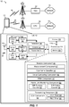
- a wireless communications system 10 includes at least one UE 12 in communication coverage of at least one eNodeB 14.
- UE 12 may communicate with a first radio access technology (RAT) network (e.g., an LTE network) such as network 18 including an evolved packet core (EPC) 16 via eNodeB 14.
- RAT radio access technology
- LTE long term evolution
- EPC evolved packet core
- Multiple UEs 12 may be dispersed throughout the wireless communications system 10, and each UE 12 may be stationary or mobile.
- a UE 12 may also be referred to by those skilled in the art as a mobile station, a subscriber station, a mobile unit, a subscriber unit, a wireless unit, a remote unit, a mobile device, a wireless device, a wireless communications device, a remote device, a mobile subscriber station, an access terminal, a mobile terminal, a wireless terminal, a remote terminal, a handset, a user agent, a mobile client, a client, or some other suitable terminology.
- a UE 12 may be a cellular phone, a personal digital assistant (PDA), a wireless modem, a wireless communication device, a handheld device, a tablet computer, a laptop computer, a cordless phone, a wireless local loop (WLL) station, a global positioning system (GPS) device, a multimedia device, a video device, a digital audio player (e.g., MP3 player), a camera, a game console, a wearable computing device (e.g., a smart-watch, smart-glasses, a health or fitness tracker, etc), an appliance, a sensor, a vehicle communication system, a medical device, a vending machine, a device for the Internet-of-Things, or any other similar functioning device.
- a UE 12 may be able to communicate with macro eNodeBs, pico eNodeBs, femto eNodeBs, relays, and the like.
- An eNodeB 14 may provide a cell serving the UE 12.
- multiple UEs such as UE 12 may be in communication coverage with one or more eNodeBs, including eNodeB 14.
- An eNodeB 14 may be a station that communicates with the UE 12 and may also be referred to as a base station, an access point, a NodeB, etc.
- Each eNodeB, such as eNodeB 14 may provide communication coverage for a particular geographic area.
- the term "cell" can refer to a coverage area of an eNodeB 14 and/or an eNodeB subsystem serving the coverage area, depending on the context in which the term is used.
- the eNodeB 14 may be the cell where the UE 12 initially performs a connection establishment procedure. Such a cell may be referred to as a primary cell or Pcell. Another eNodeB (not shown) may be operating on another frequency and may be referred to as a secondary cell. It should be apparent that an eNodeB may operate as either a primary cell or a secondary cell depending on the connection state of the UE 12.
- a cell ID such as a primary cell identifier (PCI) may be mapped to an eNodeB.
- a UE may be within the coverage areas of multiple eNodeBs. One of these eNodeBs may be selected to serve the UE. The serving eNodeB may be selected based on various criteria including radio resource monitoring measurements and radio link monitoring measurements such as received power, path loss, signal-to-noise ratio (SNR), etc.
- SNR signal-to-noise ratio
- An eNodeB 14 may provide communication coverage for a macro cell, a small cell, a pico cell, a femto cell, and/or other types of cell.
- a macro cell may cover a relatively large geographic area (e.g., several kilometers in radius) and may allow unrestricted access by UEs 12 with service subscription.
- the term "small cell,” as used herein, refers to a relatively low transmit power and/or a relatively small coverage area cell as compared to a transmit power and/or a coverage area of a macro cell.
- small cell may include, but is not limited to, cells such as a femto cell, a pico cell, access point base stations, Home NodeBs, femto access points, or femto cells.
- a macro cell may cover a relatively large geographic area, such as, but not limited to, several kilometers in radius.
- a pico cell may cover a relatively small geographic area and may allow unrestricted access by UEs 12 with service subscription.
- a femto cell may cover a relatively small geographic area (e.g., a home) and may allow restricted access by a UE 12 having association with the femto cell (e.g., UE 12 may be subscribed to a Closed Subscriber Group (CSG), for users in the home, etc.).
- An eNodeB 14 for a macro cell may be referred to as a macro eNodeB.
- An eNodeB 14 for a pico cell may be referred to as a pico eNodeB.
- An eNodeB 14 for a femto cell may be referred to as a femto eNodeB or a home eNodeB.
- a UE 12 may also be in communication with a second RAT network such as network 24.
- the network 24 may be for example, a UTRA, CDMA, GSM, WiMax or other wide area network.
- the network 24 may also include a Wi-Fi local area network (LAN) or other similar network.
- the UE 12 may communicate with the network 24 via a base station 20.
- the base station 20 may be a station that communicates with the UE 12 and may also be referred to as an eNodeB, an access point, a NodeB, etc.
- the network 24 may also include a radio network controller 22 or other intermediate nodes such as routers, switches, etc.
- the network 24 may provide a service to be used simultaneously with the network 18.
- the network 24 may provide voice services while the network 18 provides data services.
- the UE 12 may periodically monitor the network 24 for paging or other signaling even when no call with the network 24 is currently active.
- the base station 20 may be an eNodeB similar to eNodeB 14 and may be in communication with the EPC 16.
- the UE 12 may be configured for performing measurements and monitoring for one or more of eNodeB 14 or base station 20.
- the UE 12 may include one or more processors 103 that may operate in combination with a modem component 40 for performing measurements and monitoring on received radio frequency (RF) signals.
- the modem component 40 may receive communications 26 from eNodeB 14, which may include reference signals such as a cell-specific reference signal (CRS).
- CRS cell-specific reference signal
- the UE 12 may also receive signals 28, which may, at least in some cases, interfere with the communications 26 and produce different RRM and RLM measurements. For example, during guaranteed transmissions the signals 28 may interfere with the communications 26, whereas during opportunistic transmissions the communications 26 may only occur if the signals 28 are not present.
- the communications 26 received during opportunistic transmissions may produce higher RRM and RLM measurements.
- the term "component" as used herein may be one of the parts that make up a system, may be hardware, firmware, and/or software, and may be divided into other components.
- the modem component 40 may be communicatively coupled to a transceiver 106, which may include a receiver 32 for receiving and processing RF signals and a transmitter 34 for processing and transmitting RF signals.
- the modem component 40 may include a measurement component 42 for obtaining measurements of a received RF signal, a sub-frame classifier 44 for identifying received sub-frames as either opportunistic transmissions or guaranteed transmissions, a value computing component 46 for computing measurement values based on obtained measurements for particular sub-frames or for subsets of sub-frames, a radio resource monitoring (RRM) component 48 for evaluating RRM measurement values, a radio link monitoring component 50 for monitoring a radio link between an eNodeB 14 and the UE 12, and a transmitting component 60 for performing uplink transmissions.
- RRM radio resource monitoring
- the receiver 32 may include hardware, firmware, and/or software code executable by a processor for receiving data, the code comprising instructions and being stored in a memory (e.g., computer-readable medium).
- the receiver 32 may be, for example, a radio frequency (RF) receiver.
- the receiver 32 may receive signals transmitted by the eNodeB 14.
- the receiver 32 may obtain measurements of the signals. For example, the receiver 32 may determine Ec/Io, SNR, a power amplitude of one or more signals, etc.
- the transmitter 34 may include hardware, firmware, and/or software code executable by a processor for transmitting data, the code comprising instructions and being stored in a memory (e.g., computer-readable medium).
- the transmitter 34 may be, for example, a RF transmitter.
- the one or more processors 103 can include one or more modem processors forming a modem 108.
- the various functions related to modem component 40 may be included in modem 108 and/or processors 103 and, in an aspect, can be executed by a single processor, while in other aspects, different ones of the functions may be executed by a combination of two or more different processors.
- the one or more processors 103 may include any one or any combination of a modem processor, or a baseband processor, or a digital signal processor, or a transmit processor, or a transceiver processor associated with transceiver 106.
- the one or more processors 103 may implement components included in modem component 40, including the measurement component 42 for obtaining measurements of a received RF signal, the sub-frame classifier 44 for identifying received sub-frames as either opportunistic transmissions or guaranteed transmissions, the value computing component 46 for computing measurement values based on obtained measurements for particular sub-frames or for subsets of sub-frames, the RRM component 48 for evaluating RRM measurement values, the radio link monitoring component 50 for monitoring the radio link between an eNodeB 14 and the UE 12, and the transmitting component 60 for performing uplink transmissions.
- the measurement component 42 for obtaining measurements of a received RF signal
- the sub-frame classifier 44 for identifying received sub-frames as either opportunistic transmissions or guaranteed transmissions
- the value computing component 46 for computing measurement values based on obtained measurements for particular sub-frames or for subsets of sub-frames
- the RRM component 48 for evaluating RRM measurement values
- the radio link monitoring component 50 for monitoring the radio link between
- the measurement component 42 may include hardware, firmware, and/or software code executable by a processor (e.g., processor(s) 103) for obtaining measurements of a received RF signal.
- the measurement component 42 may include or control an RF receive chain including, for example, an antenna 102, RF front end 104, and the receiver 32.
- the measurement component 42 may obtain measurements or samples for each sub-frame or for individual symbols, or portions thereof, within a sub-frame.
- the measurement component 42 may obtain a received signal power amplitude, a reference signal power amplitude, a cell specific reference signal (CRS) measurement, etc.
- CRS cell specific reference signal
- the sub-frame classifier 44 may include hardware, firmware and/or software code executable by a processor (e.g., processor(s) 103) for identifying a first set of sub-frames including opportunistic transmissions and a second subset of sub-frames including guaranteed transmissions.
- the sub-frame classifier 44 may include a processor configured to classify sub-frames based on measurements obtained during each sub-frame as well as a downlink frame structure and signaling.
- guaranteed sub-frames may be determined based on a downlink frame structure.
- the eNodeB 14 may indicate in advance (e.g.
- the sub-frames designated for D-CET transmission may be considered as members of the first set of sub-frames including opportunistic transmissions.
- the sub-frames including opportunistic transmissions may be determined to be any sub-frame that does not include a guaranteed transmission.
- the sub-frame classifier 44 may further classify opportunistic sub-frames based on the presence of a cell specific reference signal (CRS) or an enhanced cell specific reference signal (eCRS).
- CRS cell specific reference signal
- eCRS enhanced cell specific reference signal
- sub-frames with a CRS or eCRS outside of the D-CET may be considered opportunistic sub-frame.
- Sub-frames that do not include a CRS or eCRS may be considered to be unused sub-frames (e.g., because the spectrum was unavailable).
- the UE 12 may consider sub-frames including a CRS or eCRS when determining RLM measurement values.
- the value computing component 46 may include hardware, firmware, and/or software code executable by a processor (e.g., processor(s) 103) for computing measurement values based on obtained measurements for particular sub-frames or for subsets of sub-frames.
- the value computing component 46 may compute a reference signal received power (RSRP) value by filtering reference signal amplitude measurements across both guaranteed sub-frames and opportunistic sub-frames.
- RSRP reference signal received power
- filtering may include measuring the reference signal amplitude measurements during both guaranteed sub-frames and opportunistic sub-frames.
- a weight or forgetting factor may be applied to place more emphasis on recent sub-frames.
- the value computing component 46 may determine separate received signal strength indicator (RSSI) values based on subsets of sub-frames. For example, a first RSSI value, RSSI OPP , may be based on received signal amplitude measurements during opportunistic sub-frames. A second RSSI value, RSSI CET , may be based on received signal amplitude measurements during guaranteed sub-frames.
- the value computing component 46 may compute separate reference signal received quality (RSRQ) values based on subsets of sub-frames. For example, the value computing component 46 may compute a first RSRQ value, RSRQ OPP , based on a number of used resource blocks (N) the RSRP value and the RSSI OPP value.
- RSSI received signal strength indicator
- the RSRQ OPP may be (N * RSRP) / RSSI OPP
- the value computing component 46 may compute a second RSRQ value, RSRQ CET , based on the number of used resource blocks, the RSRP value and the RSSI CET value.
- RSRQ CET may be (N * RSRP) / RSSI CET .
- the value computing component 46 may also compute separate signal to interference plus noise ratio (SINR) values based on subsets of sub-frames.
- SINR signal to interference plus noise ratio
- the value computing component 46 may compute a first SINR value, SINR OPP , for a subset of sub-frames including opportunistic transmissions.
- the SINR value may be based on measurements of the CRS or eCRS.
- the value computing component 46 may not be able to compute an accurate SINR OPP value.
- the eNodeB 14 may not be able to transmit a CRS or eCRS during opportunistic sub-frames. Accordingly, the CRS measurements may not be available during opportunistic sub-frames.
- the SINR OPP value may also be considered unavailable when an unreliable value is produced based on insufficient measurements.
- the SINR OPP value may be considered unreliable when the UE 12 does not receive a threshold number of sub-frames including a CRS or eCRS.
- the value computing component 46 may indicate whether the SINR OPP value is available.
- the value computing component 46 may compute a second SINR value, SINR CET , based on CRS measurements associated with guaranteed sub-frames.
- the RRM component 48 may include hardware, firmware, and/or software code executable by a processor (e.g., processor(s) 103) for evaluating RRM measurement values.
- the RRM component 48 may be configured by the eNodeB to monitor for certain types of events such as cell change events. For example, the RRM component 48 may compare an RRM measurement of the eNodeB 14 to a threshold value or an RRM measurement for another base station 20. In an aspect, the eNodeB 14 may configure which measurement values to compare.
- the RRM component 48 may be configured to compare RSRQ OPP to a threshold value. The RSRQ OPP may, for example, be compared for events A1, A2, or A4, where only a single cell is involved.
- the RSRQ OPP value may provide a more realistic measurement for actual conditions during the opportunistic transmissions.
- the RRM component 48 may be configured to compare the RSRQ CET value measured for eNodeB 14 to an RSRQ CET value determined for another eNodeB.
- the RSRQ CET may, for example, be compared for events A3 or A5, where the serving cell is compared to a neighbor cell.
- the RSRQ CET may be better for comparing eNodeBs because the RSRQ CET may account for interference.
- the RRM component 48 may transmit a measurement report using transmitting component 60.
- the measurement report may trigger a cell change such as a handover or cell reselection.
- the radio link monitoring component 50 may include hardware, firmware, and/or software code executable by a processor (e.g., processor(s) 103) for monitoring a radio link between an eNodeB 14 and the UE 12.
- the radio link monitoring component 50 may include or may be implemented by a receiver configured to demodulate and decode received RF signals.
- the radio link monitoring component 50 may demodulate and decode system information blocks (SIBs) transmitted by the eNodeB 14.
- the eNodeB 14 may transmit a SIB every 80 milliseconds (ms).
- the radio link monitoring component 50 may be further configured to determine whether decoding of each SIB is successful.
- the radio link monitoring component 50 may include a SIB success counter 52 and a SIB failure counter 54.
- the SIB success counter 52 may include a memory (e.g., RAM) configured to maintain a count of successful SIB decodings.
- the SIB success counter 52 may indicate a number of consecutive successful SIB decodings, or a number of successful SIB decodings during a period of time.
- the SIB failure counter 54 may include a memory (e.g., RAM) configured to indicate a number of consecutive unsuccessful or failed SIB decodings, or a number of unsuccessful SIB decodings during a period of time.
- the radio link monitoring component 50 may be further configured to monitor a radio link condition of the wireless device based on the SINR values, the SIB success counter 52, and/or the SIB failure counter 54.
- monitoring the radio link condition of the wireless device includes determining whether the UE 12 is synchronized with the eNodeB 14.
- the radio link monitoring component 50 may determine whether the UE 12 is synchronized with the eNodeB 14 by comparing the SINR OPP value with a threshold value.
- the threshold value may be configurable by the eNodeB 14.
- the radio link monitoring component 50 may determine that the UE 12 is synchronized when the SINR CET value exceeds a first threshold value or the value of the SIB success counter 52 exceeds a second threshold value. Conversely, when the SINR OPP value is unavailable, the radio link monitoring component 50 may determine that the UE 12 is not synchronized when the SINR CET value is less than the first threshold value and the value of the SIB failure counter 54 exceeds a second threshold.
- the first threshold value and the second threshold value may be configured by the eNodeB 14.
- the radio link monitoring component 50 may determine that a radio link failure (RLF) has occurred when the UE 12 is not synchronized with the eNodeB 14.
- RLF radio link failure
- the transmitting component 60 may include hardware, firmware, and/or software code executable by a processor (e.g., processor(s) 103) for performing uplink transmissions.
- the transmitting component 60 may include or control a transmitter (e.g., transmitter 34).
- the transmitting component 60 may include a clear channel assessment (CCA) component 62, a CCA timer 64, and a radio link control (RLC) timer 66.
- CCA clear channel assessment
- RLC radio link control
- the CCA component 62 may include hardware, firmware, and/or software code executable by a processor (e.g., processor(s) 103) configured to determine whether a channel is available for a transmission. In an aspect, the CCA component 62 may use measurements provided by the measurement component 42 to determine the received signal energy on a channel. In another aspect, CCA component 62 may include a receiver (not shown) configured to measure received signal energy on a channel. CCA component 62 may determine that a channel is clear when the signal energy falls below a threshold value. In an aspect, CCA component 62 may determine whether a channel is available according to regulations or a standard. For example, EN 301.893 may define LBT procedures. IEEE 802.11 and 802.15 standards may define CCA procedures.
- the CCA procedures may involve monitoring a channel for a CCA duration or time slot, for example 20 microseconds ( ⁇ s). If the time slot is clear (e.g., the communications medium is available or accessible (signal energy falls below a threshold value)), the device may begin using the channel. If the channel is not clear, the device may determine a random backoff counter for the channel. Each time the device detects a clear time slot, the random backoff counter may be decremented.
- the UE 12 may perform clear channel assessment before an uplink transmission procedure.
- an uplink transmission procedure may include a random access channel (RACH) procedure.
- RACH random access channel
- the uplink transmission procedure may include a scheduled uplink transmission in a sub-frame.
- the CCA component 62 may perform a CCA procedure before the scheduled uplink sub-frame.
- the UE 12 may continue to transmit in subsequent consecutive sub-frames. If the UE 110 is not scheduled to transmit in a sub-frame, the CCA component 62 may perform a CCA procedure again before the next scheduled uplink sub-frame.
- the CCA procedure may not be completed within a time period. For example, another wireless device may be transmitting on the channel and the UE 12 may be unable to access the channel.
- an uplink CCA exempt transmission may be defined as a transmission for which the UE 12 is not required to perform a CCA procedure. Similar to D-CET, U-CET may be limited to a certain percentage of sub-frames or a minimum time between U-CET sub-frames. In an aspect, the U-CET sub-frame timing may be based on the D-CET sub-frame timing.
- the CCA timer 64 may be configured to measure a duration of time used for a CCA procedure.
- the CCA timer 64 may be configured with a maximum duration for a CCA procedure.
- the CCA timer 64 may be started when the CCA procedure is initiated by the media access (MAC) layer for certain transmissions.
- the CCA timer 64 may be used for RACH transmissions such as a timing advance, a random access message 1 identifying the UE 12, a scheduling request, or a buffer status report.
- the UE 12 When operating in unlicensed spectrum, the UE 12 may not be able to perform a RACH transmission immediately due to the CCA procedure. Accordingly, a number of RACH transmissions may not be indicative of radio link quality.
- the CCA timer 64 may be used to determine whether RACH transmissions are successful. In another aspect, the CCA timer 64 may also be started for a scheduled transmission in an uplink sub-frame. If the CCA timer exceeds the configured duration, the transmitting component 60 may declare an RLF because the UE 12 is unable to transmit.
- the RLC timer 66 may be configured to measure a duration of time used for a transmission at the RLC layer.
- the RLC protocol may use an acknowledged mode to determine whether protocol data units (PDUs) have been successfully transmitted.
- the transmitting component may generate an RLC PDU and start the RLC timer 66 when the RLC PDU is transmitted to lower layers. If the RLC layer does not receive an acknowledgement for the RLC PDU, the transmitting component 60 may retransmit the RLC PDU. Because of the CCA procedure at the physical (PHY) layer, RLC retransmission in unlicensed spectrum may not have a fixed round-trip time, so the number of retransmissions may not be indicative of the radio link quality.
- PHY physical
- the RLC layer may transmit the PDU a single time, but be unable to perform a retransmission due to channel usage. Therefore, even though the channel conditions are poor, the PDU may have no retransmissions.
- the RLC timer 66 may be configured with a maximum duration for RLC transmissions. For example, the RLC timer 66 may be started each time an RLC PDU is transmitted.
- the transmitting component 60 may declare an RLF after a maximum number of RLC retransmissions for the PDU or when the RLC timer 66 for the PDU exceeds the maximum duration.
- UE 12 may include RF front end 104 and transceiver 106 for receiving and transmitting radio transmissions, for example, communications 26 transmitted by the eNodeB 14 or base station 20.
- transceiver 106 may receive a signal that includes a reference signal (e.g., CRS)) from each network entity, such as communications 26 from eNodeB 14 and signal 28 from base station 20, which in this example combine to form received signal 31.
- the transceiver 106 may measure the received reference signal in order to determine signal quality and for providing feedback to the eNodeB 14.
- transceiver 106 may communicate with modem 108 to transmit messages (e.g., radio resource control messages based on RRM measurements) generated by modem component 40 and to receive messages (e.g. radio resource control commands) and forward them to modem component 40.
- messages e.g., radio resource control messages based on RRM measurements
- receive messages e.g. radio resource control commands
- RF front end 104 may be connected to one or more antennas 102 and can include one or more low-noise amplifiers (LNAs) 141, one or more switches 142, 143, one or more power amplifiers (PAs) 145, and one or more filters 144 for transmitting and receiving RF signals.
- LNAs low-noise amplifiers
- PAs power amplifiers
- filters 144 for transmitting and receiving RF signals.
- components of RF front end 104 can connect with transceiver 106.
- Transceiver 106 may connect to one or more modems 108 and processor 103.
- LNA 141 can amplify a received signal at a desired output level.
- each LNA 141 may have a specified minimum and maximum gain values.
- RF front end 104 may use one or more switches 142, 143 to select a particular LNA 141 and its specified gain value based on a desired gain value for a particular application.
- the RF front end 104 may provide measurements (e.g., Ec/Io) and/or applied gain values to the modem component 40.
- one or more PA(s) 145 may be used by RF front end 104 to amplify a signal for an RF output at a desired output power level.
- each PA 145 may have a specified minimum and maximum gain values.
- RF front end 104 may use one or more switches 143, 146 to select a particular PA 145 and its specified gain value based on a desired gain value for a particular application.
- one or more filters 144 can be used by RF front end 104 to filter a received signal to obtain an input RF signal.
- a respective filter 144 can be used to filter an output from a respective PA 145 to produce an output signal for transmission.
- each filter 144 can be connected to a specific LNA 141 and/or PA 145.
- RF front end 104 can use one or more switches 142, 143, 146 to select a transmit or receive path using a specified filter 144, LNA, 141, and/or PA 145, based on a configuration as specified by transceiver 106 and/or processor 103.
- Transceiver 106 may be configured to transmit and receive wireless signals through antenna 102 via RF front end 104.
- transceiver may be tuned to operate at specified frequencies such that UE 12 can communicate with, for example, eNodeB 14 or base station 20.
- modem 108 can configure transceiver 106 to operate at a specified frequency and power level based on the UE configuration of the UE 12 and communication protocol used by modem 108.
- modem 108 can be a multiband-multimode modem, which can process digital data and communicate with transceiver 106 such that the digital data is sent and received using transceiver 106.
- modem 108 can be multiband and be configured to support multiple frequency bands for a specific communications protocol.
- modem 108 can be multimode and be configured to support multiple operating networks and communications protocols.
- modem 108 can control one or more components of UE 12 (e.g., RF front end 104, transceiver 106) to enable transmission and/or reception of signals from the network based on a specified modem configuration.
- the modem configuration can be based on the mode of the modem and the frequency band in use.
- the modem configuration can be based on UE configuration information associated with UE 12 as provided by the network during cell selection and/or cell reselection.
- UE 12 may further include a memory 130, such as for storing data used herein and/or local versions of applications or modem component 40 and/or one or more of its subcomponents being executed by processor 103.
- Memory 130 can include any type of computer-readable medium usable by a computer or processor 103, such as random access memory (RAM), read only memory (ROM), tapes, magnetic discs, optical discs, volatile memory, non-volatile memory, and any combination thereof.
- memory 130 may be a computer-readable storage medium that stores one or more computer-executable codes defining modem component 40 and/or one or more of its subcomponents, and/or data associated therewith, when UE 12 is operating processor 103 to execute modem component 40 and/or one or more of its subcomponents.
- memory 130 may be a non-transitory computer-readable storage medium.
- FIGS. 2-5 illustrate flowcharts of example methods that may be performed, for example, by a UE such as UE 12 ( FIG. 1 ). While, for purposes of simplicity of explanation, the methods are shown and described as a series of acts, it is to be understood and appreciated that the methods (and further methods related thereto) is/are not limited by the order of acts, as some acts may, in accordance with one or more aspects, occur in different orders and/or concurrently with other acts from that shown and described herein. For example, it is to be appreciated that a method could alternatively be represented as a series of interrelated states or events, such as in a state diagram. Moreover, not all illustrated acts may be required to implement a method in accordance with one or more features described herein.
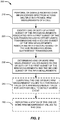
- a UE such as UE 12 ( FIG. 1 ) may perform an aspect of a method 200 of wireless communication.
- the method 200 may include performing, on signals received over an unlicensed spectrum across multiple sub-frames, RRM measurements of a cell.
- the measurement component 42 may perform, on the signals received over the unlicensed spectrum across the multiple sub-frames, the RRM measurements of a cell.
- performing the RRM measurements may include measuring a reference signal received power (RSRP) for a first subset of sub-frames and for a second subset of sub-frames.
- performing the RRM measurements may include measuring a first received signal strength indicator (RSSI) for a first subset of sub-frames and a second RSSI for a second subset of sub-frames.
- RSSI received signal strength indicator
- the method 200 may include identifying one or both of a first subset of the RRM measurements associated with a first subset of the sub-frames including opportunistic transmissions and a second subset of the RRM measurements associated with a second subset of the sub-frames including guaranteed transmissions.
- the sub-frame classifier 44 may identify the first subset of the RRM measurements associated with the first subset of the sub-frames including opportunistic transmissions and the second subset of the RRM measurements associated with the second subset of the sub-frames including guaranteed transmissions.
- the method 200 may include determining one or more RRM measurement values based on one or both of the first subset of the RRM measurements and the second subset of the RRM measurements.
- the value computing component 46 may determine the one or more RRM measurement values based on one or both of the first subset of the RRM measurements and the second subset of the RRM measurements.
- determining the one or more RRM measurement values may include combining, into a single RSRP value, the RSRP measurements associated with the first set of sub-frames and the RSRP measurements associated with the second set of sub-frames.
- the value computing component 46 may combine the RSRP measurements by computing a weighted average of the RSRP measurements associated with the first set of sub-frames and the RSRP measurements associated with the second set of sub-frames. The weights may be based on the number of sub-frames in each set.
- determining the one or more RRM measurement values may include determining a first reference signal received quality (RSRQ) value for the first set of sub-frames based on the first RSSI measurements and a second RSRQ value for the second set of sub-frames based on the second RSSI measurements.
- RSSI reference signal received quality
- the method 200 may optionally include comparing the one or more RRM measurement values to a threshold value or an RRM measurement value for another cell to detect an RRM event.
- the RRM component 48 may compare the one or more RRM measurement values to the threshold value or the RRM measurement value for another cell to detect the RRM event.
- the RRM component 48 may compare the first RSRQ value to a threshold value.
- the RRM component 48 may compare the second RSRQ value to a received signal quality for a reference signal for a different cell.
- the eNodeB 14 may signal which RRM measurement values to compare.
- the method 200 may optionally include reporting a status of the one or more RRM measurement values to the cell.
- the transmitting component 60 may report a status of the one or more RRM measurement values to the cell.
- the transmitting component 60 may send a measurement report indicating the RRM measurement values or the event detected by the RRM measurement values.
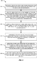
- a UE such as UE 12 ( FIG. 1 ) may perform an aspect of a method 300 of wireless communication.
- the method 300 may include measuring, across multiple sub-frames received over an unlicensed spectrum, received cell-specific reference signals (CRS) from a cell to obtain CRS measurements.
- CRS cell-specific reference signals
- the measurement component 42 may measure, across multiple sub-frames received over an unlicensed spectrum, the received CRS from a cell provided by the eNodeB 14 to obtain CRS measurements.
- the method 300 may include identifying one or both of a first subset of the CRS measurements associated with a first subset of the sub-frames including opportunistic transmissions and a second subset of the CRS measurements associated with a second subset of the sub-frames including guaranteed transmissions.
- the sub-frame classifier 44 may identify the first subset of the CRS measurements associated with the first subset of the sub-frames including opportunistic transmissions and the second subset of the CRS measurements associated with the second subset of the sub-frames including guaranteed transmissions.
- the method 300 may include computing one or both of a first signal to interference plus noise ratio (SINR) value for the first subset of CRS measurements and a second SINR value for the second subset of CRS measurements.
- SINR signal to interference plus noise ratio
- the value computing component 46 may compute the first SINR value for the first subset of CRS measurements and/or the second SINR value for second subset of CRS measurements.
- the value computing component 46 may compute a SINR OPP for the first set of CRS measurements and/or compute a SINR CET for the second subset of the CRS measurements.
- the method 300 may optionally include determining, for each of a plurality of SIBs broadcast by the cell, a decoding status indicating whether the decoding of a respective SIB was successful.
- a radio link monitoring component 50 may decode the plurality of SIBs broadcast by the cell; determine, for each of the SIBs, a decoding status indicating whether the decoding of a respective SIB was successful; and maintain a first counter (e.g., SIB failure counter 54) of decodings of the SIBs having an unsuccessful decoding status, and a second counter (e.g., SIB success counter 52) of decodings of the SIBs having a successful decoding status.
- a first counter e.g., SIB failure counter 54
- a second counter e.g., SIB success counter 52
- the method 300 may include monitoring a radio link condition of the wireless device based at least in part on a first SINR value computed for the first subset of CRS measurements or a second SINR value computed for the second subset of CRS measurements.
- the radio link monitoring component 50 may monitor a radio link condition of the wireless device based at least in part on a first SINR value computed for the first subset of CRS measurements or a second SINR value computed for the second subset of CRS measurements.
- monitoring the radio link condition of the wireless device may include determining whether the wireless device is synchronized with the cell.
- monitoring the radio link condition of the wireless device may include determining that the first SINR value is available and determining whether the wireless device is synchronized with the cell based on the first SINR value. For example, the radio link monitoring component 50 may determine that the wireless device is synchronized when the first SINR value is available and exceeds a threshold, and determine that the wireless device is not synchronized when the first SINR value is available and is less than the threshold. In another aspect, monitoring the radio link condition of the wireless device may include determining that the first SINR value is not currently available and determining that the wireless device is not synchronized with the cell when the second SINR value indicates that the wireless device is not synchronized with the cell and the first counter exceeds a threshold number of unsuccessful decodings.
- monitoring the radio link condition of the wireless device may include determining that the first SINR value is not currently available and determining that the wireless device is synchronized with the cell when the second SINR value indicates that the wireless device is synchronized with the cell or the second counter exceeds a threshold number of successful decodings.
- the method 300 may optionally include declaring a radio link failure when monitoring the radio link condition of the wireless device indicates that the wireless device is not synchronized with the cell.
- the radio link monitoring component 50 may declare a radio link failure when monitoring the radio link condition of the wireless device indicates that the wireless device is not synchronized with the cell.
- the UE 12 may attempt to reconnect to a cell and report the RLF.
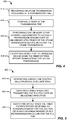
- a UE such as UE 12 ( FIG. 1 ) may perform an aspect of a method 400 of wireless communication.
- the method 400 may include triggering an uplink transmission procedure at a transmission time.
- the transmitting component 60 may trigger the uplink transmission procedure at the transmission time.
- the uplink transmission procedure may be a random access procedure or an uplink data transmission procedure.
- the transmission time may be a time when the transmitting component 60 first triggers the transmission.
- the method 400 may include starting a timer at the transmission time.
- the CCA timer 64 may start at the transmission time.
- the method 400 may include performing one or more clear channel assessments to access a transmission medium over an unlicensed spectrum for the uplink transmission before initiating the uplink transmission.
- the CCA component 62 may perform the one or more clear channel assessments to access the transmission medium over an unlicensed spectrum for the uplink transmission before initiating the uplink transmission.
- the method 400 may include identifying an RLF for the wireless device when the timer expires before transmitting the uplink transmission.
- the transmitting component 60 may identify an RLF for the wireless device when the timer expires before transmitting the uplink transmission.
- the UE 12 may attempt to reconnect to a cell and report the RLF.
- a UE such as UE 12 ( FIG. 1 ) may perform an aspect of a method 500 of wireless communication.
- the method 500 may include generating a radio link control (RLC) protocol data unit (PDU).
- the transmitting component 60 may generate a radio link control (RLC) protocol data unit (PDU).
- the method 500 may include starting a timer when first transmitting the RLC PDU over an unlicensed spectrum.
- the RLC timer 66 may be started when first transmitting the RLC PDU over an unlicensed spectrum.
- a duration of the timer may be configured based on a radio bearer associated with the RLC PDU.
- the method 500 may include identifying an RLF when the timer expires before receiving an acknowledgment for the RLC PDU or when a maximum number of RLC retransmissions occur for the RLC PDU.
- the transmitting component 60 may identify an RLF when the timer expires before receiving an acknowledgment for the RLC PDU or when a maximum number of RLC retransmissions occur for the RLC PDU.
- the UE 12 may attempt to reconnect to a cell and report the radio link failure.
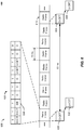
- FIG. 6 is a block diagram conceptually illustrating an example of a frame structure 600 in a telecommunications system in accordance with an aspect of the present disclosure.
- the transmission timeline for the downlink may be partitioned into units of radio frames 602.
- Each radio frame 602 may have a predetermined duration (e.g., 10 milliseconds (ms), 4 ms, or 2 ms) and may be partitioned into, e.g., 10 sub-frames 620 with indices of 0 through 9.
- a first D-CET transmission 630 may occur during one of the radio frames 610.
- the D-CET transmission may use one or more sub-frames 620.
- the D-CET transmission 630 may be followed by a U-CET transmission 632 in a later sub-frame of the same radio frame, or in a different radio frame.
- a second D-CET transmission 634 may occur during a later radio frame 610.
- the second D-CET transmission 634 may be scheduled, for example, 80 ms after the D-CET transmission 630.
- a second U-CET transmission 636 may follow the second D-CET transmission 634.
- the U-CET transmissions 632, 634 may be duplexed using the same carrier as the downlink transmissions.
- the U-CET transmissions 632, 634 may be transmitted on a second carrier, which may be synchronized with the downlink carrier.
- the sub-frames 620 used for the D-CET transmissions may be considered sub-frames associated with guaranteed transmissions. For example, sub-frames with indices 0 and 1 may be associated with guaranteed transmissions.
- the other sub-frames 620 may be considered sub-frames associated with opportunistic transmissions.
- the frame structure 600 may also include SIBs 640 transmitted by the eNodeB 14.
- a SIB 640 may include information about the eNodeB 14 such as timing information, access parameters, RRM measurement configuration, RLM measurement configuration, neighbor lists, etc.
- the SIBs 640 may be periodically transmitted.
- a SIB 640 may be transmitted every 80 ms.
- the SIBs 640 may be transmitted within the D-CET transmissions 630 or may be transmitted in opportunistic sub-frames.
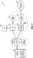
- FIG. 7 is a diagram illustrating a long term evolution (LTE) network architecture 700 employing various apparatuses of wireless communications system 10 ( FIG. 1 ) and may include one or more UEs 12 ( FIG. 1 ) having a modem component 40, where the UE 12 may correspond to user equipment 702, for example.
- the LTE network architecture 700 may be referred to as an Evolved Packet System (EPS) 700.
- EPS 700 may include one or more user equipment (UE) 702, an Evolved UMTS Terrestrial Radio Access Network (E-UTRAN) 704, an Evolved Packet Core (EPC) 780, a Home Subscriber Server (HSS) 720, and an Operator's IP Services 722.
- UE user equipment
- E-UTRAN Evolved UMTS Terrestrial Radio Access Network
- EPC Evolved Packet Core
- HSS Home Subscriber Server
- the EPS can interconnect with other access networks, but for simplicity those entities/interfaces are not shown. As shown, the EPS provides packet-switched services, however, as those skilled in the art will readily appreciate, the various concepts presented throughout this disclosure may be extended to networks providing circuit-switched services.
- the E-UTRAN includes the evolved Node B (eNB) 706 and other eNBs 708.
- the eNB 706 and 708 may each be an example of an eNodeB 14 ( FIG. 1 ).
- the eNBs 706, 708 may receive measurement reports transmitted from the UE 702 including a modem component 40.
- the eNB 706 may configure the modem component 40 of the UE 702 to perform physical layer procedures including radio measurements and event reporting.
- the eNB 706 may indicate which measurement values to determine and which events to report. For example, the eNB 706 may indicate whether the UE 702 should use the RSRQ OPP or the RSRQ CET .
- the eNB 706 provides user and control plane protocol terminations toward the UE 702.
- the eNB 708 may be connected to the other eNBs 708 via an X2 interface (i.e., backhaul).
- the eNB 706 may also be referred to by those skilled in the art as a base station, a base transceiver station, a radio base station, a radio transceiver, a transceiver function, a basic service set (BSS), a small cell, an extended service set (ESS), or some other suitable terminology.
- the eNB 706 provides an access point to the EPC 780 for a UE 702.
- the eNB 706 is connected by an S1 interface to the EPC 780.
- the EPC 780 includes a Mobility Management Entity (MME) 762, other MMEs 764, a Serving Gateway 766, and a Packet Data Network (PDN) Gateway 768.
- MME 762 is the control node that processes the signaling between the UE 702 and the EPC 780.
- the MME 762 provides bearer and connection management. All user IP packets are transferred through the Serving Gateway 766, which itself is connected to the PDN Gateway 768.
- the PDN Gateway 768 provides UE IP address allocation as well as other functions.
- the PDN Gateway 768 is connected to the Operator's IP Services 722.
- the Operator's IP Services 722 includes the Internet, the Intranet, an IP Multimedia Subsystem (IMS), and a PS Streaming Service (PSS).
- IMS IP Multimedia Subsystem
- PSS PS Streaming Service
- FIG. 8 is a block diagram conceptually illustrating an exemplary base station 810 and an exemplary UE 850 configured in accordance with an aspect of the present disclosure.
- the base station 810 and the UE 850 may be an example of the eNodeB 14 and of the UE 12 in FIG. 1 , respectively.
- the UE 850 may include a modem component 40.
- the base station 810 may be equipped with antennas 834 1-t
- the UE 850 may be equipped with antennas 852 1-r , wherein t and r are integers greater than or equal to one.
- a base station transmit processor 820 may receive data from a base station data source 812 and control information from a base station controller/processor 840.
- the control information may be carried on the PBCH, PCFICH, PHICH, PDCCH, etc.
- the data may be carried on the PDSCH, etc.
- the base station transmit processor 820 may process (e.g., encode and symbol map) the data and control information to obtain data symbols and control symbols, respectively.
- the base station transmit processor 820 may also generate reference symbols, e.g., for the PSS, SSS, and cell-specific reference signal (CRS).
- reference symbols e.g., for the PSS, SSS, and cell-specific reference signal (CRS).
- a base station transmit (TX) multiple-input multiple-output (MIMO) processor 830 may perform spatial processing (e.g., precoding) on the data symbols, the control symbols, and/or the reference symbols, if applicable, and may provide output symbol streams to the base station modulators/demodulators (MODs/DEMODs) 832 1-t .
- Each base station modulator/demodulator 832 may process a respective output symbol stream (e.g., for OFDM, etc.) to obtain an output sample stream.
- Each base station modulator/demodulator 832 may further process (e.g., convert to analog, amplify, filter, and upconvert) the output sample stream to obtain a downlink signal.
- Downlink signals from modulators/demodulators 832 1-t may be transmitted via the antennas 834 1-t , respectively.
- the UE antennas 852 1-r may receive the downlink signals from the base station 810 and may provide received signals to the UE modulators/demodulators (MODs/DEMODs) 854 1-r , respectively.
- Each UE modulator/demodulator 854 may condition (e.g., filter, amplify, downconvert, and digitize) a respective received signal to obtain input samples.
- Each UE modulator/demodulator 854 may further process the input samples (e.g., for OFDM, etc.) to obtain received symbols.
- a UE MIMO detector 856 may obtain received symbols from all the UE modulators/demodulators 854 1-r , and perform MIMO detection on the received symbols if applicable, and provide detected symbols.
- a UE reception processor 858 may process (e.g., demodulate, deinterleave, and decode) the detected symbols, provide decoded data for the UE 850 to a UE data sink 860, and provide decoded control information to a UE controller/processor 880.
- a UE transmit processor 864 may receive and process data (e.g., for the PUSCH) from a UE data source 862 and control information (e.g., for the PUCCH) from the UE controller/processor 880.
- the UE transmit processor 864 may also generate reference symbols for a reference signal.
- the symbols from the UE transmit processor 864 may be precoded by a UE TX MIMO processor 866 if applicable, further processed by the UE modulator/demodulators 854 1-r (e.g., for SC-FDM, etc.), and transmitted to the base station 810.
- the uplink signals from the UE 850 may be received by the base station antennas 834, processed by the base station modulators/demodulators 832, detected by a base station MIMO detector 836 if applicable, and further processed by a base station reception processor 838 to obtain decoded data and control information sent by the UE 850.
- the base station reception processor 838 may provide the decoded data to a base station data sink 846 and the decoded control information to the base station controller/processor 840.
- the base station controller/processor 840 and the UE controller/processor 880 may direct the operation at the base station 810 and the UE 850, respectively.
- the base station controller/processor 840 and/or other processors and modules at the base station 810 may perform or direct, e.g., the execution of various processes for the techniques described herein.
- the controller/processor 880 may implement the modem component 40 ( FIG. 1 ).
- the UE controller/processor 880 and/or other processors and modules at the UE 850 may also perform or direct, e.g., the physical layer procedures, measurements, event reporting, RLF detection, and/or other processes for the techniques described herein.
- the base station memory 842 and the UE memory 882 may store data and program codes for the base station 810 and the UE 850, respectively.
- a scheduler 844 may schedule UEs 850 for data transmission on the downlink and/or uplink.
- DSP digital signal processor
- ASIC application specific integrated circuit
- FPGA field programmable gate array
- a general-purpose processor may be a microprocessor, but in the alternative, the processor may be any conventional processor, controller, microcontroller, or state machine.
- a processor may also be implemented as a combination of computing devices, e.g., a combination of a DSP and a microprocessor, a plurality of microprocessors, one or more microprocessors in conjunction with a DSP core, or any other such configuration.
- a software module may reside in RAM memory, flash memory, ROM memory, EPROM memory, EEPROM memory, registers, hard disk, a removable disk, a CD-ROM, or any other form of storage medium known in the art.
- An exemplary storage medium is coupled to the processor such that the processor can read information from, and write information to, the storage medium.
- the storage medium may be integral to the processor.
- the processor and the storage medium may reside in an ASIC.
- the ASIC may reside in a user terminal or base station.
- the processor and the storage medium may reside as discrete components in a user terminal or base station.
- the functions described may be implemented in hardware, software, firmware, or any combination thereof. If implemented in software, the functions may be stored on or transmitted over as one or more instructions or code on a computer-readable medium.
- Computer-readable media includes both computer storage media and communication media including any medium that facilitates transfer of a computer program from one place to another.
- a storage media may be any available media that can be accessed by a general purpose or special purpose computer.
- such computer-readable media can comprise RAM, ROM, EEPROM, CD-ROM or other optical disk storage, magnetic disk storage or other magnetic storage devices, or any other medium that can be used to carry or store desired program code means in the form of instructions or data structures and that can be accessed by a general-purpose or special-purpose computer, or a general-purpose or special-purpose processor. Also, any connection is properly termed a computer-readable medium.
- Disk and disc includes compact disc (CD), laser disc, optical disc, digital versatile disc (DVD), floppy disk and Blu-ray disc where disks usually reproduce data magnetically, while discs reproduce data optically with lasers. Combinations of the above should also be included within the scope of computer-readable media.
Landscapes
- Engineering & Computer Science (AREA)
- Signal Processing (AREA)
- Computer Networks & Wireless Communication (AREA)
- Quality & Reliability (AREA)
- Physics & Mathematics (AREA)
- Electromagnetism (AREA)
- Mobile Radio Communication Systems (AREA)
Claims (11)
- Ein Verfahren für eine Vorrichtung zur Durchführung von Messungen auf der Steuerebene in einem drahtlosen Gerät (12, 702, 850), aufweisend:Durchführen (210), auf Signalen empfangen über ein unlizenziertes Spektrum über mehrere Unterrahmen (620), von Messungen des Funkressourcen-Managements, RRM, für eine Zelle, wobei Durchführen der RRM-Messungen beinhaltet Messen der Leistung des empfangenen Referenzsignals, RSRP, um zu erhalten RSRP-Messungen zugeordnet zu einer ersten Untermenge der Unterrahmen (620) enthaltend opportunistische Übertragungen und RSRP-Messungen zugeordnet zu der zweiten Untermenge der Unterrahmen (620) enthaltend garantierte Übertragungen, wobei opportunistische Übertragungen vorkommen, wenn ein Träger oder ein Kanal gewisse Bedingungen erfüllt, wobei eine opportunistische Übertragung einer Prozedur der Kanal-Frei-Prüfung, CCA, oder einer Prozedur der erweiterten CCA, E-CCA vor Übertragung unterliegt, und wobei garantierte Übertragungen garantiert zu einer bestimmten Zeit stattfinden, wobei die bestimmte Zeit, zu der die garantierten Übertragungen stattfinden, ein Unterrahmen für Übertragungen, D-CET, ohne Kanal-Frei-Prüfung, CCA, der Abwärtsverbindung ist;Identifizieren (220) einer ersten Untermenge der RRM-Messungen zugeordnet zu der ersten Untermenge der Unterrahmen (620) und einer zweiten Untermenge der RRM-Messungen zugeordnet zu der zweiten Untermenge der Unterrahmen (620); undBestimmen (230) von einem oder mehreren RRM-Messwerten basierend auf der ersten Untermenge der RRM-Messungen und der zweiten Untermenge der RRM-Messungen, wobei Bestimmen des einen oder der mehreren RRM-Messwerte beinhaltet Kombinieren, in einen einzigen RSRP-Wert, der RSRP-Messungen zugeordnet zu der ersten Untermenge der Unterrahmen (620) mit den RSRP-Messungen zugeordnet zu der zweiten Untermenge der Unterrahmen (620).
- Das Verfahren aus Anspruch 1, wobei:Durchführen der RRM-Messungen beinhaltet Messen eines ersten Stärkenindikators des Empfängersignals, RSSI, zugeordnet zu der ersten Untermenge der Unterrahmen (620) und eines zweiten RSSI zugeordnet zu der zweiten Untermenge der Unterrahmen (620); undBestimmen des einen oder der mehreren RRM-Messwerte beinhaltet Bestimmen eines ersten Wertes der Empfangsqualität des Referenzsignals, RSRQ, für die erste Untermenge der Unterrahmen (620) basierend auf dem ersten RSSI und Bestimmen eines zweiten RSRQ-Wertes für die zweite Untermenge der Unterrahmen (620) basierend auf dem zweiten RSSI.
- Das Verfahren aus Anspruch 2, weiter aufweisend Vergleichen des ersten RSRQ-Wertes mit einem Grenzwert, um ein RRM-Ereignis festzustellen.
- Das Verfahren aus Anspruch 2, weiter aufweisend Vergleichen des zweiten RSRQ-Wertes mit einer empfangenen Signalqualität für ein Referenzsignal für eine verschiedene Zelle, um ein RRM-Ereignis festzustellen.
- Das Verfahren aus Anspruch 2, weiter aufweisend Empfangen, von einem Netzwerk aus, einer Indikation, welcher von dem ersten RSRQ-Wert und dem zweiten RSRQ-Wert durch das drahtlose Gerät (12, 702, 850) benutzt werden soll.
- Eine Vorrichtung zur Durchführung von Messungen auf der Steuerebene in einem drahtlosen Gerät (12, 702, 850), aufweisend:Mittel zum Durchführen, auf Signalen empfangen über ein unlizenziertes Spektrum über mehrere Unterrahmen (620), von Messungen des Funkressourcen-Managements, RRM, für eine Zelle, wobei die Mittel zum Durchführen der RMM-Messungen weiterhin sind zum Messen der Leistung des empfangenen Referenzsignals, RSRP, um zu erhalten RSRP-Messungen zugeordnet zu einer ersten Untermenge der Unterrahmen (620) und RSRP-Messungen zugeordnet zu der zweiten Untermenge der Unterrahmen (620), wobei opportunistische Übertragungen vorkommen, wenn ein Träger oder ein Kanal gewisse Bedingungen erfüllt, wobei eine opportunistische Übertragung einer Prozedur der Kanal-Frei-Prüfung, CCA, oder einer Prozedur der erweiterten CCA, E-CCA, vor Übertragung unterliegt, und wobei garantierte Übertragungen garantiert zu einer bestimmten Zeit stattfinden, wobei die bestimmte Zeit, zu der die garantierten Übertragungen stattfinden, ein Unterrahmen für Übertragungen, D-CET, ohne Kanal-Frei-Prüfung, CCA, der Abwärtsverbindung ist;Mittel zum Identifizieren einer ersten Untermenge der RRM-Messungen zugeordnet zu der ersten Untermenge der Unterrahmen (620) und einer zweiten Untermenge der RRM-Messungen zugeordnet zu der zweiten Untermenge der Unterrahmen (620); undMittel zum Bestimmen von einem oder mehreren RRM-Messwerten basierend auf der ersten Untermenge der RRM-Messungen und der zweiten Untermenge der RRM-Messungen, wobei die Mittel zum Bestimmen des einen oder der mehreren Messwerte weiterhin sind zum Kombinieren, in einen einzigen RSRP-Wert, der RSRP-Messungen zugeordnet zu der ersten Untermenge der Unterrahmen (620) mit den RSRP-Messungen zugeordnet zu der zweiten Untermenge der Unterrahmen (620).
- Die Vorrichtung aus Anspruch 6, wobei:die Mittel zum Durchführen der RRM-Messungen sind weiterhin zum Messen eines ersten Stärkenindikators des Empfängersignals, RSSI, zugeordnet zu der ersten Untermenge der Unterrahmen (620) und eines zweiten RSSI zugeordnet zu der zweiten Untermenge der Unterrahmen (620), unddie Mittel zum Bestimmen des einen oder der mehreren RRM-Messwerte sind weiterhin zum Bestimmen eines ersten Wertes der Empfangsqualität des Referenzsignals, RSRQ, für die erste Untermenge der Unterrahmen (620) basierend auf dem ersten RSSI und Bestimmen eines zweiten RSRQ-Wertes für die zweite Untermenge der Unterrahmen (620) basierend auf dem zweiten RSSI.
- Die Vorrichtung aus Anspruch 7, weiter aufweisend Mittel zum Vergleichen des ersten RSRQ-Wertes mit einem Grenzwert, um ein RRM-Ereignis festzustellen.
- Die Vorrichtung aus Anspruch 7, weiter aufweisend Mittel zum Vergleichen des zweiten RSRQ-Wertes mit einer empfangenen Signalqualität für ein Referenzsignal für eine verschiedene Zelle, um ein RRM-Ereignis festzustellen.
- Die Vorrichtung aus Anspruch 7, weiter aufweisend Mittel zum Empfangen, von einem Netzwerk aus, einer Indikation, welcher von dem ersten RSRQ-Wert und dem zweiten RSRQ-Wert durch das drahtlose Gerät (12, 702, 850) benutzt werden soll.
- Ein computerlesbares Medium speichernd computer-ausführbaren Code zum Durchführen eines Verfahrens gemäß einem der Ansprüche 1 bis 5, wenn sie durch eine Vorrichtung ausgeführt werden.
Priority Applications (1)
| Application Number | Priority Date | Filing Date | Title |
|---|---|---|---|
| EP19165840.0A EP3522665B1 (de) | 2014-10-03 | 2015-10-02 | Physikalische schichtverfahren für lte in unlizenziertem spektrum |
Applications Claiming Priority (3)
| Application Number | Priority Date | Filing Date | Title |
|---|---|---|---|
| US201462059670P | 2014-10-03 | 2014-10-03 | |
| US14/873,079 US10009925B2 (en) | 2014-10-03 | 2015-10-01 | Physical layer procedures for LTE in unlicensed spectrum |
| PCT/US2015/053844 WO2016054584A2 (en) | 2014-10-03 | 2015-10-02 | Physical layer procedures for lte in unlicensed spectrum |
Related Child Applications (2)
| Application Number | Title | Priority Date | Filing Date |
|---|---|---|---|
| EP19165840.0A Division EP3522665B1 (de) | 2014-10-03 | 2015-10-02 | Physikalische schichtverfahren für lte in unlizenziertem spektrum |
| EP19165840.0A Division-Into EP3522665B1 (de) | 2014-10-03 | 2015-10-02 | Physikalische schichtverfahren für lte in unlizenziertem spektrum |
Publications (2)
| Publication Number | Publication Date |
|---|---|
| EP3202211A2 EP3202211A2 (de) | 2017-08-09 |
| EP3202211B1 true EP3202211B1 (de) | 2019-05-08 |
Family
ID=54330893
Family Applications (2)
| Application Number | Title | Priority Date | Filing Date |
|---|---|---|---|
| EP15781832.9A Not-in-force EP3202211B1 (de) | 2014-10-03 | 2015-10-02 | Durchführung von messungen von übertragungen, die in einem drahtlosen gerät empfangen sind |
| EP19165840.0A Active EP3522665B1 (de) | 2014-10-03 | 2015-10-02 | Physikalische schichtverfahren für lte in unlizenziertem spektrum |
Family Applications After (1)
| Application Number | Title | Priority Date | Filing Date |
|---|---|---|---|
| EP19165840.0A Active EP3522665B1 (de) | 2014-10-03 | 2015-10-02 | Physikalische schichtverfahren für lte in unlizenziertem spektrum |
Country Status (8)
| Country | Link |
|---|---|
| US (2) | US10009925B2 (de) |
| EP (2) | EP3202211B1 (de) |
| JP (1) | JP6549222B2 (de) |
| KR (2) | KR102519585B1 (de) |
| CN (2) | CN106797571B (de) |
| AU (1) | AU2015327897B2 (de) |
| BR (1) | BR112017006574A2 (de) |
| WO (1) | WO2016054584A2 (de) |
Families Citing this family (33)
| Publication number | Priority date | Publication date | Assignee | Title |
|---|---|---|---|---|
| US10009925B2 (en) | 2014-10-03 | 2018-06-26 | Qualcomm Incorporated | Physical layer procedures for LTE in unlicensed spectrum |
| US10123350B2 (en) * | 2015-02-06 | 2018-11-06 | Htc Corporation | Communication device and wireless communication system for handling random access procedure |
| US11457433B2 (en) * | 2015-04-08 | 2022-09-27 | Interdigital Patent Holdings, Inc. | Systems and methods for LTE operation in unlicensed bands |
| US10225859B2 (en) * | 2015-05-14 | 2019-03-05 | Qualcomm Incorporated | Techniques for uplink transmission management |
| US10142996B2 (en) * | 2015-07-03 | 2018-11-27 | Nokia Technologies Oy | Sensitivity tuning in wireless networks |
| EP3437359B1 (de) * | 2016-04-01 | 2022-06-01 | Telefonaktiebolaget LM Ericsson (PUBL) | Verfahren zur steuerung von relativen messungen in gegenwart von lbt |
| JP2018026662A (ja) | 2016-08-09 | 2018-02-15 | ソニー株式会社 | 通信装置、通信方法、及びプログラム |
| CN106255124B (zh) * | 2016-09-09 | 2022-12-20 | 宇龙计算机通信科技(深圳)有限公司 | 通信方法和通信装置 |
| US10244399B2 (en) * | 2016-09-30 | 2019-03-26 | Qualcomm Incorporated | Signature sequence-based signaling and allocation of resources of a shared spectrum |
| CN110178405B (zh) * | 2016-12-21 | 2022-02-01 | 瑞典爱立信有限公司 | 用于无线通信系统中的链路切换的方法和装置 |
| US10070462B2 (en) * | 2017-01-31 | 2018-09-04 | Qualcomm Incorporated | Listen before transmit (LBT) communication protocol for vehicle-to-vehicle communications |
| US11153857B2 (en) * | 2017-02-11 | 2021-10-19 | Lg Electronics Inc. | Method for physical uplink control channel transmission/reception between terminal and base station in wireless communication system, and apparatus supporting same |
| CN111096059B (zh) * | 2017-08-16 | 2023-09-05 | Lg电子株式会社 | 在未授权频带中管理无线电链路的方法和设备 |
| CN109600784B (zh) | 2017-09-30 | 2021-10-22 | 中兴通讯股份有限公司 | 上报信号质量的方法及装置 |
| CN117641575A (zh) | 2017-11-14 | 2024-03-01 | 交互数字专利控股公司 | 在不活动状态中运行双连接 |
| CN109451822B (zh) * | 2017-11-29 | 2022-05-24 | 北京小米移动软件有限公司 | 无线链路状态确定方法和无线链路状态确定装置 |
| US11357015B2 (en) * | 2017-12-22 | 2022-06-07 | Qualcomm Incorporated | Sidelink signal measurement and resource selection in vehicle-to-everything communications |
| WO2019200603A1 (en) | 2018-04-20 | 2019-10-24 | Zte Corporation | Apparatus and method for mobility management |
| WO2019214985A1 (en) * | 2018-05-09 | 2019-11-14 | Sony Corporation | Methods and devices for polarization optimization of mimo wireless transmission |
| US11956822B2 (en) | 2018-06-19 | 2024-04-09 | Interdigital Patent Holdings, Inc. | Radio link monitoring in shared spectrum |
| WO2020029198A1 (zh) * | 2018-08-09 | 2020-02-13 | 富士通株式会社 | 无线链路检测方法、装置和通信系统 |
| EP3827530B1 (de) * | 2018-09-27 | 2023-05-10 | Apple Inc. | Funkverbindungsüberwachung und -versagen für unlizensierten betrieb in new radio |
| CN110972315A (zh) * | 2018-09-28 | 2020-04-07 | 索尼公司 | 用于无线通信的电子设备和方法、计算机可读存储介质 |
| CN111107659B (zh) | 2018-10-26 | 2022-03-11 | 华为技术有限公司 | 非授权频谱中无线链路检测的方法和通信装置 |
| CN111132365B (zh) * | 2018-10-31 | 2022-07-12 | 展讯通信(上海)有限公司 | 上行传输方法、装置、计算机可读存储介质及终端 |
| EP3664494A1 (de) * | 2018-12-05 | 2020-06-10 | INTEL Corporation | Verfahren und vorrichtungen für kommunikation von vorrichtung zu vorrichtung |
| US20220060247A1 (en) * | 2018-12-20 | 2022-02-24 | Ntt Docomo, Inc. | Radio node and radio communication method |
| WO2020034549A1 (en) * | 2018-12-28 | 2020-02-20 | Zte Corporation | Methods, apparatus and systems for indicating transmission failures in a wireless communication |
| CN111585732B (zh) * | 2019-02-15 | 2022-02-25 | 华为技术有限公司 | 通信方法和通信设备 |
| WO2021056129A1 (en) * | 2019-09-23 | 2021-04-01 | Qualcomm Incorporated | Trigger radio link control radio link failure to avoid data stall |
| US11184055B2 (en) | 2020-04-24 | 2021-11-23 | Apple Inc. | MIMO transmission using fewer antennas for communication |
| KR20220108951A (ko) * | 2021-01-28 | 2022-08-04 | 삼성전자주식회사 | 전자 장치 및 전자 장치에서 시스템 정보 요청을 전송하는 방법 |
| US11515953B1 (en) * | 2021-08-05 | 2022-11-29 | Qualcomm Incorporated | Low noise amplifier saturation mitigation |
Family Cites Families (29)
| Publication number | Priority date | Publication date | Assignee | Title |
|---|---|---|---|---|
| US20090190480A1 (en) | 2007-12-11 | 2009-07-30 | Interdigital Patent Holdings, Inc. | Methods and apparatus for detecting radio link control protocol errors and triggering radio link control re-establishment |
| US20090175175A1 (en) | 2008-01-04 | 2009-07-09 | Interdigital Patent Holdings, Inc. | Radio link control reset using radio resource control signaling |
| US20130153298A1 (en) | 2009-02-19 | 2013-06-20 | Interdigital Patent Holdings, Inc. | Method and apparatus for enhancing cell-edge user performance and signaling radio link failure conditions via downlink cooperative component carriers |
| US8711709B2 (en) * | 2009-03-12 | 2014-04-29 | Interdigital Patent Holdings, Inc. | Method and apparatus for monitoring for a radio link failure |
| US8958833B2 (en) * | 2009-05-22 | 2015-02-17 | Qualcomm Incorporated | Systems, apparatus and methods for interference management on downlink channels in wireless communication systems |
| BR112012020879B1 (pt) * | 2010-02-22 | 2021-06-15 | Guangdong Oppo Mobile Telecommunications Corp., Ltd | Detecção de falha de link de rádio (rlf) para recuperação |
| KR101850720B1 (ko) * | 2010-03-29 | 2018-04-20 | 엘지전자 주식회사 | 무선 통신 시스템에서 셀간 간섭 조정에 대한 측정 방법 및 장치 |
| US9144040B2 (en) * | 2010-04-01 | 2015-09-22 | Futurewei Technologies, Inc. | System and method for uplink multi-antenna power control in a communications system |
| US9125072B2 (en) | 2010-04-13 | 2015-09-01 | Qualcomm Incorporated | Heterogeneous network (HetNet) user equipment (UE) radio resource management (RRM) measurements |
| US8712401B2 (en) | 2010-04-16 | 2014-04-29 | Qualcomm Incorporated | Radio link monitoring (RLM) and reference signal received power (RSRP) measurement for heterogeneous networks |
| EP2594101A1 (de) * | 2010-07-14 | 2013-05-22 | Research In Motion Limited | Hybride mobilitätsverfahren im ruhemodus in einem heterogenen netzwerk |
| EP3989473B1 (de) | 2010-12-03 | 2024-02-14 | Samsung Electronics Co., Ltd. | Verfahren und vorrichtung für drahtlose kommunikation auf mehreren spektrumsbändern |
| EP2649744B1 (de) * | 2010-12-06 | 2020-08-19 | InterDigital Patent Holdings, Inc. | Verfahren zur aktivierung von drahtlosbetrieb in einem lizenzfreien spektrum |
| US10123345B2 (en) * | 2010-12-22 | 2018-11-06 | Google Technology Holdings LLC | Interference mitigation in a device supporting multiple radio technologies communicating in overlapping time periods |
| US9497676B2 (en) * | 2011-01-11 | 2016-11-15 | Ntt Docomo, Inc. | User equipment and measurement method |
| US9419776B2 (en) * | 2011-02-07 | 2016-08-16 | Interdigital Patent Holdings, Inc. | Method and apparatus for operating supplementary cells in licensed exempt spectrum |
| WO2012106843A1 (en) | 2011-02-11 | 2012-08-16 | Renesas Mobile Corporation | Signaling method to enable controlled tx deferring in mixed licensed and unlicensed spectrum carrier aggregation in future lte-a networks |
| US20120213108A1 (en) * | 2011-02-22 | 2012-08-23 | Qualcomm Incorporated | Radio resource monitoring (rrm) and radio link monitoring (rlm) procedures for remote radio head (rrh) deployments |
| EP2698000A4 (de) | 2011-04-11 | 2015-04-22 | Nokia Corp | Vorrichtung und verfahren zur verringerung der interferenz zwischen getrennten kommunikationssystemen |
| WO2012148141A2 (ko) * | 2011-04-25 | 2012-11-01 | 엘지전자 주식회사 | 캐리어 병합을 위한 자원 구성 방법 및 이를 위한 장치 |
| CN103765824B (zh) | 2011-07-14 | 2017-03-22 | 美国博通公司 | 用于在系统的未许可频带上提供灵活时间共享方案的方法和装置 |
| WO2013089531A1 (ko) * | 2011-12-16 | 2013-06-20 | 엘지전자 주식회사 | 다중 셀 시스템에서 물리 채널에 대한 자원 매핑 방법 및 장치 |
| KR101615987B1 (ko) * | 2011-12-22 | 2016-05-11 | 엘지전자 주식회사 | 무선 접속 시스템에서 무선 통신 상태 측정 방법 및 이를 위한 장치 |
| WO2013141544A1 (en) | 2012-03-18 | 2013-09-26 | Lg Electronics Inc. | Method and apparatus for performing measurement in wireless communication system |
| CN103686781B (zh) * | 2012-09-17 | 2018-07-17 | 中兴通讯股份有限公司 | Csi-rsrp测量周期的配置方法及终端 |
| KR20160146971A (ko) * | 2014-04-25 | 2016-12-21 | 후아웨이 테크놀러지 컴퍼니 리미티드 | 기지국, 사용자 기기, 자원 획득 방법 및 시스템 |
| US11363615B2 (en) * | 2014-05-22 | 2022-06-14 | Kyocera Corporation | Assignment of communication resources in an unlicensed frequency band to equipment operating in a licensed frequency band |
| KR102247085B1 (ko) * | 2014-09-01 | 2021-04-30 | 삼성전자주식회사 | 비인가 주파수 대역을 사용하는 이동통신 시스템에서의 통신 기법 |
| US10009925B2 (en) | 2014-10-03 | 2018-06-26 | Qualcomm Incorporated | Physical layer procedures for LTE in unlicensed spectrum |
-
2015
- 2015-10-01 US US14/873,079 patent/US10009925B2/en active Active
- 2015-10-02 WO PCT/US2015/053844 patent/WO2016054584A2/en active Application Filing
- 2015-10-02 EP EP15781832.9A patent/EP3202211B1/de not_active Not-in-force
- 2015-10-02 CN CN201580053291.3A patent/CN106797571B/zh not_active Expired - Fee Related
- 2015-10-02 KR KR1020227020360A patent/KR102519585B1/ko active IP Right Grant
- 2015-10-02 AU AU2015327897A patent/AU2015327897B2/en not_active Ceased
- 2015-10-02 KR KR1020177008779A patent/KR102411048B1/ko active IP Right Grant
- 2015-10-02 BR BR112017006574A patent/BR112017006574A2/pt active Search and Examination
- 2015-10-02 JP JP2017517710A patent/JP6549222B2/ja not_active Expired - Fee Related
- 2015-10-02 EP EP19165840.0A patent/EP3522665B1/de active Active
- 2015-10-02 CN CN202010078750.6A patent/CN111294807B/zh active Active
-
2018
- 2018-04-24 US US15/961,606 patent/US10721770B2/en active Active
Non-Patent Citations (1)
| Title |
|---|
| None * |
Also Published As
| Publication number | Publication date |
|---|---|
| WO2016054584A3 (en) | 2016-05-12 |
| WO2016054584A2 (en) | 2016-04-07 |
| JP6549222B2 (ja) | 2019-07-24 |
| KR102519585B1 (ko) | 2023-04-06 |
| US10009925B2 (en) | 2018-06-26 |
| CN111294807A (zh) | 2020-06-16 |
| BR112017006574A2 (pt) | 2017-12-19 |
| US20180249505A1 (en) | 2018-08-30 |
| CN106797571A (zh) | 2017-05-31 |
| KR20170066380A (ko) | 2017-06-14 |
| CN111294807B (zh) | 2023-07-14 |
| US10721770B2 (en) | 2020-07-21 |
| JP2017530649A (ja) | 2017-10-12 |
| KR102411048B1 (ko) | 2022-06-17 |
| AU2015327897A1 (en) | 2017-03-09 |
| AU2015327897B2 (en) | 2019-10-24 |
| KR20220090585A (ko) | 2022-06-29 |
| CN106797571B (zh) | 2020-03-27 |
| EP3202211A2 (de) | 2017-08-09 |
| US20160100433A1 (en) | 2016-04-07 |
| EP3522665B1 (de) | 2021-08-25 |
| EP3522665A1 (de) | 2019-08-07 |
Similar Documents
| Publication | Publication Date | Title |
|---|---|---|
| US10721770B2 (en) | Physical layer procedures for LTE in unlicensed spectrum | |
| US11770855B2 (en) | Random access channel (RACH) procedure design | |
| US9787569B2 (en) | Radio access technology co-existence using adaptive energy detection | |
| US9143957B2 (en) | Mitigating cross-device interference | |
| US9762361B2 (en) | Timer configuration for secondary cells in LTE/LTE-A networks using unlicensed spectrum | |
| WO2019143708A1 (en) | Beam recovery procedure using a second component carrier | |
| WO2018093860A1 (en) | Self-contained transmissions for machine type communications | |
| EP3706463A1 (de) | Verfahren und benutzergerät zur adaptiven funkverbindungsüberwachung | |
| TWI713552B (zh) | 用於增強型機器類型通信(eMTC)之行動性設計 | |
| JP2018524948A (ja) | マシンタイプコミュニケーションのための設定可能な測定ギャップおよびウィンドウ | |
| US20150351121A1 (en) | Protected cet transmission and reception | |
| US10588135B2 (en) | Techniques for handling bursty interference in a shared radio frequency spectrum band | |
| US10952154B2 (en) | Managing unwanted transmissions | |
| WO2021258266A1 (en) | Switch to non-standalone mode in case of a network configuration beyond ue capability |
Legal Events
| Date | Code | Title | Description |
|---|---|---|---|
| STAA | Information on the status of an ep patent application or granted ep patent |
Free format text: STATUS: THE INTERNATIONAL PUBLICATION HAS BEEN MADE |
|
| PUAI | Public reference made under article 153(3) epc to a published international application that has entered the european phase |
Free format text: ORIGINAL CODE: 0009012 |
|
| STAA | Information on the status of an ep patent application or granted ep patent |
Free format text: STATUS: REQUEST FOR EXAMINATION WAS MADE |
|
| 17P | Request for examination filed |
Effective date: 20170222 |
|
| AK | Designated contracting states |
Kind code of ref document: A2 Designated state(s): AL AT BE BG CH CY CZ DE DK EE ES FI FR GB GR HR HU IE IS IT LI LT LU LV MC MK MT NL NO PL PT RO RS SE SI SK SM TR |
|
| AX | Request for extension of the european patent |
Extension state: BA ME |
|
| DAV | Request for validation of the european patent (deleted) | ||
| DAX | Request for extension of the european patent (deleted) | ||
| STAA | Information on the status of an ep patent application or granted ep patent |
Free format text: STATUS: EXAMINATION IS IN PROGRESS |
|
| 17Q | First examination report despatched |
Effective date: 20180829 |
|
| GRAP | Despatch of communication of intention to grant a patent |
Free format text: ORIGINAL CODE: EPIDOSNIGR1 |
|
| STAA | Information on the status of an ep patent application or granted ep patent |
Free format text: STATUS: GRANT OF PATENT IS INTENDED |
|
| RIC1 | Information provided on ipc code assigned before grant |
Ipc: H04W 74/08 20090101AFI20181107BHEP |
|
| INTG | Intention to grant announced |
Effective date: 20181128 |
|
| GRAS | Grant fee paid |
Free format text: ORIGINAL CODE: EPIDOSNIGR3 |
|
| GRAA | (expected) grant |
Free format text: ORIGINAL CODE: 0009210 |
|
| STAA | Information on the status of an ep patent application or granted ep patent |
Free format text: STATUS: THE PATENT HAS BEEN GRANTED |
|
| AK | Designated contracting states |
Kind code of ref document: B1 Designated state(s): AL AT BE BG CH CY CZ DE DK EE ES FI FR GB GR HR HU IE IS IT LI LT LU LV MC MK MT NL NO PL PT RO RS SE SI SK SM TR |
|
| REG | Reference to a national code |
Ref country code: GB Ref legal event code: FG4D |
|
| REG | Reference to a national code |
Ref country code: CH Ref legal event code: EP Ref country code: AT Ref legal event code: REF Ref document number: 1132232 Country of ref document: AT Kind code of ref document: T Effective date: 20190515 |
|
| REG | Reference to a national code |
Ref country code: DE Ref legal event code: R096 Ref document number: 602015029984 Country of ref document: DE Ref country code: IE Ref legal event code: FG4D |
|
| REG | Reference to a national code |
Ref country code: NL Ref legal event code: MP Effective date: 20190508 |
|
| REG | Reference to a national code |
Ref country code: LT Ref legal event code: MG4D |
|
| PG25 | Lapsed in a contracting state [announced via postgrant information from national office to epo] |
Ref country code: FI Free format text: LAPSE BECAUSE OF FAILURE TO SUBMIT A TRANSLATION OF THE DESCRIPTION OR TO PAY THE FEE WITHIN THE PRESCRIBED TIME-LIMIT Effective date: 20190508 Ref country code: NO Free format text: LAPSE BECAUSE OF FAILURE TO SUBMIT A TRANSLATION OF THE DESCRIPTION OR TO PAY THE FEE WITHIN THE PRESCRIBED TIME-LIMIT Effective date: 20190808 Ref country code: AL Free format text: LAPSE BECAUSE OF FAILURE TO SUBMIT A TRANSLATION OF THE DESCRIPTION OR TO PAY THE FEE WITHIN THE PRESCRIBED TIME-LIMIT Effective date: 20190508 Ref country code: PT Free format text: LAPSE BECAUSE OF FAILURE TO SUBMIT A TRANSLATION OF THE DESCRIPTION OR TO PAY THE FEE WITHIN THE PRESCRIBED TIME-LIMIT Effective date: 20190908 Ref country code: SE Free format text: LAPSE BECAUSE OF FAILURE TO SUBMIT A TRANSLATION OF THE DESCRIPTION OR TO PAY THE FEE WITHIN THE PRESCRIBED TIME-LIMIT Effective date: 20190508 Ref country code: HR Free format text: LAPSE BECAUSE OF FAILURE TO SUBMIT A TRANSLATION OF THE DESCRIPTION OR TO PAY THE FEE WITHIN THE PRESCRIBED TIME-LIMIT Effective date: 20190508 Ref country code: LT Free format text: LAPSE BECAUSE OF FAILURE TO SUBMIT A TRANSLATION OF THE DESCRIPTION OR TO PAY THE FEE WITHIN THE PRESCRIBED TIME-LIMIT Effective date: 20190508 Ref country code: NL Free format text: LAPSE BECAUSE OF FAILURE TO SUBMIT A TRANSLATION OF THE DESCRIPTION OR TO PAY THE FEE WITHIN THE PRESCRIBED TIME-LIMIT Effective date: 20190508 |
|
| PG25 | Lapsed in a contracting state [announced via postgrant information from national office to epo] |
Ref country code: BG Free format text: LAPSE BECAUSE OF FAILURE TO SUBMIT A TRANSLATION OF THE DESCRIPTION OR TO PAY THE FEE WITHIN THE PRESCRIBED TIME-LIMIT Effective date: 20190808 Ref country code: RS Free format text: LAPSE BECAUSE OF FAILURE TO SUBMIT A TRANSLATION OF THE DESCRIPTION OR TO PAY THE FEE WITHIN THE PRESCRIBED TIME-LIMIT Effective date: 20190508 Ref country code: LV Free format text: LAPSE BECAUSE OF FAILURE TO SUBMIT A TRANSLATION OF THE DESCRIPTION OR TO PAY THE FEE WITHIN THE PRESCRIBED TIME-LIMIT Effective date: 20190508 Ref country code: GR Free format text: LAPSE BECAUSE OF FAILURE TO SUBMIT A TRANSLATION OF THE DESCRIPTION OR TO PAY THE FEE WITHIN THE PRESCRIBED TIME-LIMIT Effective date: 20190809 |
|
| REG | Reference to a national code |
Ref country code: AT Ref legal event code: MK05 Ref document number: 1132232 Country of ref document: AT Kind code of ref document: T Effective date: 20190508 |
|
| PG25 | Lapsed in a contracting state [announced via postgrant information from national office to epo] |
Ref country code: RO Free format text: LAPSE BECAUSE OF FAILURE TO SUBMIT A TRANSLATION OF THE DESCRIPTION OR TO PAY THE FEE WITHIN THE PRESCRIBED TIME-LIMIT Effective date: 20190508 Ref country code: CZ Free format text: LAPSE BECAUSE OF FAILURE TO SUBMIT A TRANSLATION OF THE DESCRIPTION OR TO PAY THE FEE WITHIN THE PRESCRIBED TIME-LIMIT Effective date: 20190508 Ref country code: SK Free format text: LAPSE BECAUSE OF FAILURE TO SUBMIT A TRANSLATION OF THE DESCRIPTION OR TO PAY THE FEE WITHIN THE PRESCRIBED TIME-LIMIT Effective date: 20190508 Ref country code: EE Free format text: LAPSE BECAUSE OF FAILURE TO SUBMIT A TRANSLATION OF THE DESCRIPTION OR TO PAY THE FEE WITHIN THE PRESCRIBED TIME-LIMIT Effective date: 20190508 Ref country code: DK Free format text: LAPSE BECAUSE OF FAILURE TO SUBMIT A TRANSLATION OF THE DESCRIPTION OR TO PAY THE FEE WITHIN THE PRESCRIBED TIME-LIMIT Effective date: 20190508 Ref country code: AT Free format text: LAPSE BECAUSE OF FAILURE TO SUBMIT A TRANSLATION OF THE DESCRIPTION OR TO PAY THE FEE WITHIN THE PRESCRIBED TIME-LIMIT Effective date: 20190508 |
|
| REG | Reference to a national code |
Ref country code: DE Ref legal event code: R097 Ref document number: 602015029984 Country of ref document: DE |
|
| PG25 | Lapsed in a contracting state [announced via postgrant information from national office to epo] |
Ref country code: IT Free format text: LAPSE BECAUSE OF FAILURE TO SUBMIT A TRANSLATION OF THE DESCRIPTION OR TO PAY THE FEE WITHIN THE PRESCRIBED TIME-LIMIT Effective date: 20190508 Ref country code: SM Free format text: LAPSE BECAUSE OF FAILURE TO SUBMIT A TRANSLATION OF THE DESCRIPTION OR TO PAY THE FEE WITHIN THE PRESCRIBED TIME-LIMIT Effective date: 20190508 |
|
| PLBE | No opposition filed within time limit |
Free format text: ORIGINAL CODE: 0009261 |
|
| STAA | Information on the status of an ep patent application or granted ep patent |
Free format text: STATUS: NO OPPOSITION FILED WITHIN TIME LIMIT |
|
| PG25 | Lapsed in a contracting state [announced via postgrant information from national office to epo] |
Ref country code: TR Free format text: LAPSE BECAUSE OF FAILURE TO SUBMIT A TRANSLATION OF THE DESCRIPTION OR TO PAY THE FEE WITHIN THE PRESCRIBED TIME-LIMIT Effective date: 20190508 |
|
| 26N | No opposition filed |
Effective date: 20200211 |
|
| PG25 | Lapsed in a contracting state [announced via postgrant information from national office to epo] |
Ref country code: PL Free format text: LAPSE BECAUSE OF FAILURE TO SUBMIT A TRANSLATION OF THE DESCRIPTION OR TO PAY THE FEE WITHIN THE PRESCRIBED TIME-LIMIT Effective date: 20190508 |
|
| PG25 | Lapsed in a contracting state [announced via postgrant information from national office to epo] |
Ref country code: SI Free format text: LAPSE BECAUSE OF FAILURE TO SUBMIT A TRANSLATION OF THE DESCRIPTION OR TO PAY THE FEE WITHIN THE PRESCRIBED TIME-LIMIT Effective date: 20190508 Ref country code: MC Free format text: LAPSE BECAUSE OF FAILURE TO SUBMIT A TRANSLATION OF THE DESCRIPTION OR TO PAY THE FEE WITHIN THE PRESCRIBED TIME-LIMIT Effective date: 20190508 |
|
| REG | Reference to a national code |
Ref country code: CH Ref legal event code: PL |
|
| PG25 | Lapsed in a contracting state [announced via postgrant information from national office to epo] |
Ref country code: LI Free format text: LAPSE BECAUSE OF NON-PAYMENT OF DUE FEES Effective date: 20191031 Ref country code: LU Free format text: LAPSE BECAUSE OF NON-PAYMENT OF DUE FEES Effective date: 20191002 Ref country code: CH Free format text: LAPSE BECAUSE OF NON-PAYMENT OF DUE FEES Effective date: 20191031 |
|
| REG | Reference to a national code |
Ref country code: BE Ref legal event code: MM Effective date: 20191031 |
|
| PG25 | Lapsed in a contracting state [announced via postgrant information from national office to epo] |
Ref country code: BE Free format text: LAPSE BECAUSE OF NON-PAYMENT OF DUE FEES Effective date: 20191031 |
|
| PG25 | Lapsed in a contracting state [announced via postgrant information from national office to epo] |
Ref country code: IE Free format text: LAPSE BECAUSE OF NON-PAYMENT OF DUE FEES Effective date: 20191002 Ref country code: ES Free format text: LAPSE BECAUSE OF FAILURE TO SUBMIT A TRANSLATION OF THE DESCRIPTION OR TO PAY THE FEE WITHIN THE PRESCRIBED TIME-LIMIT Effective date: 20190508 |
|
| PG25 | Lapsed in a contracting state [announced via postgrant information from national office to epo] |
Ref country code: CY Free format text: LAPSE BECAUSE OF FAILURE TO SUBMIT A TRANSLATION OF THE DESCRIPTION OR TO PAY THE FEE WITHIN THE PRESCRIBED TIME-LIMIT Effective date: 20190508 |
|
| PG25 | Lapsed in a contracting state [announced via postgrant information from national office to epo] |
Ref country code: IS Free format text: LAPSE BECAUSE OF FAILURE TO SUBMIT A TRANSLATION OF THE DESCRIPTION OR TO PAY THE FEE WITHIN THE PRESCRIBED TIME-LIMIT Effective date: 20190908 |
|
| PG25 | Lapsed in a contracting state [announced via postgrant information from national office to epo] |
Ref country code: MT Free format text: LAPSE BECAUSE OF FAILURE TO SUBMIT A TRANSLATION OF THE DESCRIPTION OR TO PAY THE FEE WITHIN THE PRESCRIBED TIME-LIMIT Effective date: 20190508 Ref country code: HU Free format text: LAPSE BECAUSE OF FAILURE TO SUBMIT A TRANSLATION OF THE DESCRIPTION OR TO PAY THE FEE WITHIN THE PRESCRIBED TIME-LIMIT; INVALID AB INITIO Effective date: 20151002 |
|
| PG25 | Lapsed in a contracting state [announced via postgrant information from national office to epo] |
Ref country code: MK Free format text: LAPSE BECAUSE OF FAILURE TO SUBMIT A TRANSLATION OF THE DESCRIPTION OR TO PAY THE FEE WITHIN THE PRESCRIBED TIME-LIMIT Effective date: 20190508 |
|
| PGFP | Annual fee paid to national office [announced via postgrant information from national office to epo] |
Ref country code: GB Payment date: 20220914 Year of fee payment: 8 |
|
| PGFP | Annual fee paid to national office [announced via postgrant information from national office to epo] |
Ref country code: FR Payment date: 20220916 Year of fee payment: 8 |
|
| PGFP | Annual fee paid to national office [announced via postgrant information from national office to epo] |
Ref country code: DE Payment date: 20220914 Year of fee payment: 8 |
|
| REG | Reference to a national code |
Ref country code: DE Ref legal event code: R119 Ref document number: 602015029984 Country of ref document: DE |
|
| GBPC | Gb: european patent ceased through non-payment of renewal fee |
Effective date: 20231002 |
|
| PG25 | Lapsed in a contracting state [announced via postgrant information from national office to epo] |
Ref country code: GB Free format text: LAPSE BECAUSE OF NON-PAYMENT OF DUE FEES Effective date: 20231002 |
|
| PG25 | Lapsed in a contracting state [announced via postgrant information from national office to epo] |
Ref country code: GB Free format text: LAPSE BECAUSE OF NON-PAYMENT OF DUE FEES Effective date: 20231002 Ref country code: FR Free format text: LAPSE BECAUSE OF NON-PAYMENT OF DUE FEES Effective date: 20231031 Ref country code: DE Free format text: LAPSE BECAUSE OF NON-PAYMENT OF DUE FEES Effective date: 20240501 |