EP3202166B1 - Technique for access by a master device to a value taken by a characteristic managed by a peripheral device - Google Patents
Technique for access by a master device to a value taken by a characteristic managed by a peripheral device Download PDFInfo
- Publication number
- EP3202166B1 EP3202166B1 EP15781128.2A EP15781128A EP3202166B1 EP 3202166 B1 EP3202166 B1 EP 3202166B1 EP 15781128 A EP15781128 A EP 15781128A EP 3202166 B1 EP3202166 B1 EP 3202166B1
- Authority
- EP
- European Patent Office
- Prior art keywords
- relay device
- relay
- peripheral device
- peripheral
- ble
- Prior art date
- Legal status (The legal status is an assumption and is not a legal conclusion. Google has not performed a legal analysis and makes no representation as to the accuracy of the status listed.)
- Active
Links
- 230000002093 peripheral effect Effects 0.000 title claims description 126
- 238000000034 method Methods 0.000 title claims description 46
- 238000004088 simulation Methods 0.000 claims description 9
- 238000004891 communication Methods 0.000 description 14
- 238000005516 engineering process Methods 0.000 description 14
- 241000196324 Embryophyta Species 0.000 description 13
- 230000005540 biological transmission Effects 0.000 description 12
- 238000001514 detection method Methods 0.000 description 7
- 238000005265 energy consumption Methods 0.000 description 7
- 230000004913 activation Effects 0.000 description 6
- 238000007726 management method Methods 0.000 description 6
- 230000008901 benefit Effects 0.000 description 5
- 230000015654 memory Effects 0.000 description 5
- 230000003993 interaction Effects 0.000 description 4
- 230000007246 mechanism Effects 0.000 description 4
- 230000004044 response Effects 0.000 description 4
- 241000233855 Orchidaceae Species 0.000 description 3
- 230000006870 function Effects 0.000 description 3
- 238000012545 processing Methods 0.000 description 3
- 239000002689 soil Substances 0.000 description 3
- 101100190617 Arabidopsis thaliana PLC2 gene Proteins 0.000 description 2
- 101100408456 Arabidopsis thaliana PLC8 gene Proteins 0.000 description 2
- 101100464304 Caenorhabditis elegans plk-3 gene Proteins 0.000 description 2
- 101100093534 Saccharomyces cerevisiae (strain ATCC 204508 / S288c) RPS1B gene Proteins 0.000 description 2
- 230000008859 change Effects 0.000 description 2
- 230000003287 optical effect Effects 0.000 description 2
- 239000000779 smoke Substances 0.000 description 2
- 239000000344 soap Substances 0.000 description 2
- 230000001960 triggered effect Effects 0.000 description 2
- 241001112258 Moca Species 0.000 description 1
- 241001080024 Telles Species 0.000 description 1
- 230000009471 action Effects 0.000 description 1
- 238000004590 computer program Methods 0.000 description 1
- 230000001186 cumulative effect Effects 0.000 description 1
- 230000009849 deactivation Effects 0.000 description 1
- 239000003337 fertilizer Substances 0.000 description 1
- 230000006872 improvement Effects 0.000 description 1
- 239000000463 material Substances 0.000 description 1
- 230000004048 modification Effects 0.000 description 1
- 238000012986 modification Methods 0.000 description 1
- 238000005457 optimization Methods 0.000 description 1
- 230000000737 periodic effect Effects 0.000 description 1
- 238000012163 sequencing technique Methods 0.000 description 1
- 230000007704 transition Effects 0.000 description 1
Images


Classifications
-
- H—ELECTRICITY
- H04—ELECTRIC COMMUNICATION TECHNIQUE
- H04W—WIRELESS COMMUNICATION NETWORKS
- H04W40/00—Communication routing or communication path finding
- H04W40/02—Communication route or path selection, e.g. power-based or shortest path routing
- H04W40/22—Communication route or path selection, e.g. power-based or shortest path routing using selective relaying for reaching a BTS [Base Transceiver Station] or an access point
-
- H—ELECTRICITY
- H04—ELECTRIC COMMUNICATION TECHNIQUE
- H04L—TRANSMISSION OF DIGITAL INFORMATION, e.g. TELEGRAPHIC COMMUNICATION
- H04L12/00—Data switching networks
- H04L12/28—Data switching networks characterised by path configuration, e.g. LAN [Local Area Networks] or WAN [Wide Area Networks]
- H04L12/2803—Home automation networks
-
- H—ELECTRICITY
- H04—ELECTRIC COMMUNICATION TECHNIQUE
- H04L—TRANSMISSION OF DIGITAL INFORMATION, e.g. TELEGRAPHIC COMMUNICATION
- H04L67/00—Network arrangements or protocols for supporting network services or applications
- H04L67/50—Network services
- H04L67/51—Discovery or management thereof, e.g. service location protocol [SLP] or web services
-
- H—ELECTRICITY
- H04—ELECTRIC COMMUNICATION TECHNIQUE
- H04W—WIRELESS COMMUNICATION NETWORKS
- H04W16/00—Network planning, e.g. coverage or traffic planning tools; Network deployment, e.g. resource partitioning or cells structures
- H04W16/24—Cell structures
- H04W16/26—Cell enhancers or enhancement, e.g. for tunnels, building shadow
-
- H—ELECTRICITY
- H04—ELECTRIC COMMUNICATION TECHNIQUE
- H04W—WIRELESS COMMUNICATION NETWORKS
- H04W4/00—Services specially adapted for wireless communication networks; Facilities therefor
- H04W4/80—Services using short range communication, e.g. near-field communication [NFC], radio-frequency identification [RFID] or low energy communication
-
- H—ELECTRICITY
- H04—ELECTRIC COMMUNICATION TECHNIQUE
- H04W—WIRELESS COMMUNICATION NETWORKS
- H04W52/00—Power management, e.g. TPC [Transmission Power Control], power saving or power classes
- H04W52/02—Power saving arrangements
- H04W52/0209—Power saving arrangements in terminal devices
- H04W52/0225—Power saving arrangements in terminal devices using monitoring of external events, e.g. the presence of a signal
- H04W52/0229—Power saving arrangements in terminal devices using monitoring of external events, e.g. the presence of a signal where the received signal is a wanted signal
-
- H—ELECTRICITY
- H04—ELECTRIC COMMUNICATION TECHNIQUE
- H04W—WIRELESS COMMUNICATION NETWORKS
- H04W52/00—Power management, e.g. TPC [Transmission Power Control], power saving or power classes
- H04W52/02—Power saving arrangements
- H04W52/0209—Power saving arrangements in terminal devices
- H04W52/0225—Power saving arrangements in terminal devices using monitoring of external events, e.g. the presence of a signal
- H04W52/0245—Power saving arrangements in terminal devices using monitoring of external events, e.g. the presence of a signal according to signal strength
-
- H—ELECTRICITY
- H04—ELECTRIC COMMUNICATION TECHNIQUE
- H04W—WIRELESS COMMUNICATION NETWORKS
- H04W8/00—Network data management
- H04W8/005—Discovery of network devices, e.g. terminals
-
- H—ELECTRICITY
- H04—ELECTRIC COMMUNICATION TECHNIQUE
- H04W—WIRELESS COMMUNICATION NETWORKS
- H04W28/00—Network traffic management; Network resource management
- H04W28/02—Traffic management, e.g. flow control or congestion control
- H04W28/0215—Traffic management, e.g. flow control or congestion control based on user or device properties, e.g. MTC-capable devices
-
- H—ELECTRICITY
- H04—ELECTRIC COMMUNICATION TECHNIQUE
- H04W—WIRELESS COMMUNICATION NETWORKS
- H04W84/00—Network topologies
- H04W84/02—Hierarchically pre-organised networks, e.g. paging networks, cellular networks, WLAN [Wireless Local Area Network] or WLL [Wireless Local Loop]
- H04W84/10—Small scale networks; Flat hierarchical networks
- H04W84/12—WLAN [Wireless Local Area Networks]
-
- H—ELECTRICITY
- H04—ELECTRIC COMMUNICATION TECHNIQUE
- H04W—WIRELESS COMMUNICATION NETWORKS
- H04W84/00—Network topologies
- H04W84/18—Self-organising networks, e.g. ad-hoc networks or sensor networks
-
- Y—GENERAL TAGGING OF NEW TECHNOLOGICAL DEVELOPMENTS; GENERAL TAGGING OF CROSS-SECTIONAL TECHNOLOGIES SPANNING OVER SEVERAL SECTIONS OF THE IPC; TECHNICAL SUBJECTS COVERED BY FORMER USPC CROSS-REFERENCE ART COLLECTIONS [XRACs] AND DIGESTS
- Y02—TECHNOLOGIES OR APPLICATIONS FOR MITIGATION OR ADAPTATION AGAINST CLIMATE CHANGE
- Y02D—CLIMATE CHANGE MITIGATION TECHNOLOGIES IN INFORMATION AND COMMUNICATION TECHNOLOGIES [ICT], I.E. INFORMATION AND COMMUNICATION TECHNOLOGIES AIMING AT THE REDUCTION OF THEIR OWN ENERGY USE
- Y02D30/00—Reducing energy consumption in communication networks
- Y02D30/70—Reducing energy consumption in communication networks in wireless communication networks
Definitions
- the invention relates to the general field of telecommunications.
- the invention relates more particularly to a technique for access by a master device to a value taken by a characteristic managed by a peripheral device.
- two relay devices cooperate in a service area of a local area network.
- One of the two relay devices is linked to the master device and the other relay device is linked to the peripheral device.
- a residential network includes equipment or devices located at a customer site. These devices are also called CPE, for “Customer Premise Equipment”. For a local network, it is in particular an access gateway, a “Set-Top-Box” TV decoder, a mobile terminal. In the context of a home automation network, it is also household appliances, alarm systems, sensors.
- the access gateway allows the devices of the residential network to access an extended communication network WAN (for “Wide Area Network”), such as the Internet network.
- WAN Wide Area Network
- These devices are, for example, mobile terminals, such as smart terminals (“smartphones”) or tablets. Once connected to an access point, they can thus receive data from other devices on the local network or from devices connected to the extended communication network and send data to a device on the local network or connected to the extensive communication network.
- mobile terminals such as smart terminals (“smartphones”) or tablets.
- More and more connected objects such as bracelets, watches, scales, weather sensors, are also offered to the public. These connected objects make it possible, for example, to collect data for a user or for an environment.
- a low-power wireless network is used to transmit the collected data to a device with processing capabilities. It is for example a radio access network of BLE technology, for “Bluetooth Low Energy”.
- a “central” or master BLE device can connect to connected objects to collect their data (heart rate, number of steps taken, etc.). Then, the master BLE device can optionally transmit this information via the Internet network to servers or even storage areas.
- This BLE master device is for example a terminal or smart telephone.
- the radio range for this type of access network is very limited, of the order of ten meters for example inside a dwelling.
- the master BLE device must therefore be close to the “peripheral” BLE device. Otherwise, the peripheral BLE device, although geographically present in the local network, is not accessible by the master BLE device, and its data cannot be collected or used by the latter.
- patent publication EP1742153 illustrates a system in which a first UPnP relay device detects a device connected to a first network and sends information relating to this detected device to a second UPnP relay device. The latter transmits according to the information received a message indicating that the detected device is available from a second network.
- One of the aims of the invention is to remedy shortcomings/disadvantages of the state of the art and/or to make improvements thereto.
- a peripheral device is a simple device, having only a low consumption radio access module to communicate.
- the radio access technology is for example compliant with “Bluetooth Low Energy” technology.
- the peripheral device is for example a sensor and can only be interrogated from a master device located in its vicinity. Thanks to the implementation of the method, any master device present in a service area of the local network can obtain a value of a characteristic that the peripheral device manages or measures.
- the relay devices are connected to the local network, more precisely directly or indirectly to the access gateway. These are, for example, electrical sockets with a connection Ethernet and/or by PLC carrier current (for "Power Line Carrier") and a radio access module of the same technology as the peripheral device.
- PLC carrier current for "Power Line Carrier”
- the first relay device receives an identifier of the characteristic obtained by the second relay device from the peripheral device and transmits it to the master device by means of the radio connection.
- the master device can obtain the profile of the characteristics managed by the peripheral device and select one of them. The master device can then memorize it for later interactions with the peripheral device. In another embodiment, the master device obtains it each time a connection is established. It is thus not necessary for the master device to memorize this profile.
- the method further comprises receiving an identifier of the peripheral device and to establish a radio connection, the first relay device announces the presence of the peripheral device in the radio coverage area of the master device.
- the method comprises, for the second relay device, listening to radio frequencies to detect the presence of the peripheral device and an announcement of the presence of the peripheral device.
- the first relay device announces a presence of a plurality of peripheral devices detected in a service area of a local area network.
- the presence of all the peripheral devices can be announced in the local network, the master device then selecting the peripheral device to which it wishes to access. This makes it possible to control the execution of the method from a user terminal.
- the method further comprises a command to listen to frequencies to one of the relay devices, in order to detect a presence of the peripheral device in a service area of the local area network.
- the access gateway due to its central role in the local area network, can control the execution of the method, by controlling the frequency listening phases. This makes it possible to limit the energy consumption of the relay devices.
- the transmission and reception modules of the relay devices communicate by means of electrical carrier currents.
- the system also comprises an access gateway, acting as an intermediary between the two relay devices.
- the invention relates to a program for a relay device, comprising program code instructions intended to control the execution of the steps of the access method according to the first aspect, when this program is executed by the relay device and a recording medium readable by a relay device on which is recorded a program for a device.
- European patent application EP 1742153 illustrates a master device capable of accessing a value taken by a feature managed by a peripheral device via a first and a second relay device - using SSDP protocol messages.
- the figure 1 represents, in its environment, a local communication network 2, private or residential.
- An access gateway 20 allows devices of the local area network 2 to access an extended communication network 1 or WAN (for “Wide Area Network”), such as the Internet network.
- WAN Wide Area Network
- the local network is based on various network technologies, such as a wired network of the Ethernet type according to the IEEE 802.3 standard, a wireless network of the Wi-Fi type according to the IEEE 802.11 standard or even a powerline network.
- PLC for example HomePlug ® , Alliance HD-PLC
- a network for coaxial cable of the MoCA ® type for “Multimedia over Coax”.
- the devices of the local network 2 can be any devices, for example domestic, having a wired or wireless network connection. It may be for example a terminal or mobile telephone 22, PLC sockets 21, 24, a TV decoder 27 ("Set-Top Box”), a game console (not shown).
- the gateway 20 is connected by a wired Ethernet link according to the IEEE 802.3 standard to the PLC socket 21.
- the latter communicates with the PLC socket 24 by means of a technology using carrier currents.
- This technology for example, complies with the IEEE 1901-2010 specification, entitled “IEEE Std 1901-2010, IEEE Standard for Broadband over Power Line Networks: Medium Access Control and Physical Layer Specifications”.
- the exchanges between the access gateway 20 and the PLC sockets 21, 24 comply with the UPnP network protocol, for “Universal Plug and Play”, promulgated by the UPnP forum.
- the UPnP standard aims to allow devices to easily connect and simply communicate within such a network.
- the UPnP protocol uses checkpoints.
- the access gateway 20 is a control point of the local network.
- a control point conventionally sends so-called discovery messages to the various devices of the local network in order to obtain in return a description of the devices. matching the query. These discovery messages are most often transmitted in point-to-multipoint communication mode, also called multicast, from the control point to the devices.
- a terminal device compatible with the UPnP standard responds to these request messages, and also transmits, at regular intervals, presence messages to signify that it is active and connected to the network.
- the TV decoder 27 is for its part connected to the PLC socket 24 by a wired Ethernet link and thus accesses the local network.
- the devices of the local network once connected can access the extended communication network 1 via the access gateway 20.
- a service area of the local network corresponds to a geographical area in which the devices of the local network can communicate directly or indirectly with the access gateway 20.
- This service area corresponds for example to a residential building of a user.
- PLC sockets are placed, for example, in each room of the house.
- peripheral devices In the service area of the local network, other devices, called peripheral devices, are also present. This is for example a smoke detector 25, household appliances (not shown), a sensor 26, a sensor for plants 23. These various peripheral devices are arranged to communicate on an access network radio and each include a radio access module.
- the radio access module is of the low-power radio type according to an access technology, such as Bluetooth® Low Energy BLE.
- This BLE access technology is defined by a Bluetooth SIG standardization group in the form of a set of documents, named “Bluetooth Core Specification 4.1”.
- the PLC sockets 21, 24 are also arranged to communicate on the radio access network and each comprise a radio access module of the low consumption type according to the BLE access technology. These PLC sockets act as a relay vis-à-vis the master and peripheral devices during the implementation of the method described later. These PLC sockets are thus also called relay devices.
- Smoke detector 25 and plant sensor 23 are within radio coverage area of PLC socket 24.
- Sensor 26 and mobile phone 22 are within radio coverage area of PLC socket 21.
- the size of the these coverage areas depend on the radio technology used and the environment. For BLE technology, these coverage areas are of the order of ten meters.
- the plant sensor 23 is positioned in the soil of a plant and makes it possible to measure various characteristics such as a rate of fertilizer, a rate of humidity of the soil, a temperature and a luminosity, in real time.
- An application running on the mobile phone 22 makes it possible to collect the values of these different characteristics when the mobile phone 22 is close to the plant sensor 23.
- the mobile phone 22 thus plays the role of the master device and the plant sensor 23 that of peripheral device. Due to BLE type radio technology, the maximum distance between master and peripheral devices is of the order of ten meters.
- the access gateway 20 can also have a radio access module of the Wi-Fi type. It then offers access to the extended communication network 1 to devices located in a radio coverage zone (not represented on the figure 1 ). The access gateway 20 thus communicates with devices which are located in its radio coverage area via a wireless connection, for example with the mobile telephone 22.
- the local network represented on the figure 1 corresponds to an exemplary embodiment. No limitation is attached to the number of relay devices, master devices, peripheral devices, or to the types of these devices.
- the technique of accessing a datum, corresponding to a value taken by a characteristic, in a service area of a local network in particular embodiments, implemented by the relay devices 21, 24 in collaboration with the access gateway 20 The steps are described below for the PLC socket 21 as a relay device in relation to the master device (ie the mobile telephone 22) and for the PLC socket 24 as a relay device in relation with the peripheral device (ie the sensor for plants 23).
- the access gateway 20 acts as an intermediary between the two relay devices and comprises a presence database, arranged to memorize the peripheral device(s) present in the service area of the local area network. .
- the database For a peripheral device present in the service area, the database comprises the name of the peripheral device (“Local Name”), an address, for example the MAC address, and an identifier of the relay device allowing it to be reached.
- the name of the “Local Name” peripheral device can take the values “Shortened Local Name” and “Complete Local Name”. It simply identifies the peripheral device.
- the identifier of the relay device corresponds for example to a unique universal identifier UUID (for “Universally Unique Identifier”).
- the messages exchanged between the relay device 24 and the peripheral device 23 and between the relay device 21 and the master device 22 comply with the BLE protocol.
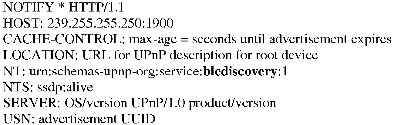
- the messages exchanged between the access gateway 20 and the relay devices 21, 24 comply with the UPnP protocol. These different devices implement a BLE discovery service called “urn:scllemas-upnp-org:service:blediscovery:l”.
- the SSDP protocol is used to discover services offered on a network, such as the blediscovery service.
- the SSDP protocol is defined by the IETF in a document draft-cai-ssdp-vl-03.txt "Simple Service Discovery Protocol/1.0 Operating without an Arbiter" of October 1999.
- the relay device 21 announces its presence on the network local by broadcasting an SSDP NOTIFY protocol notification message “ssdp:alive”.
- the relay device 21 announces that it offers the discovery service blediscovery.
- the identifier of the relay device corresponds for example to a unique universal identifier UUID (for “Universally Unique Identifier”).
- the access gateway is thus informed of the services and of the relay devices which are present in the local network
- the figure 2a represents steps of the access method in a phase of obtaining the profile of the peripheral device.
- the access gateway 20 sends a command P1 RequestBLEProfile to the relay device 24, commanding the relay device 24 to connect to the peripheral device 23 and to obtain a GATT (“Generic Attribute Profile”) profile.
- the peripheral device 23 is identified by its address, for example its MAC address, stored in the presence database. It is recalled here that the GATT profile is organized hierarchically into sections, called services, which group together data called characteristics.
- a characteristic can correspond, for example, to the battery level, the humidity level, the light level, the number of steps taken by a user, etc.
- a characteristic is identified by a unique universal identifier UUID (for "Universally Unique Identifier ").
- Such a RequestBLEProfile request is, for example, a message of the SOAP protocol layer (for “Simple Object Access Protocol”) in a UPnP network and is part of the BLE discovery service “blediscovery” described above.
- the SOAP protocol allows actions to be invoked in a UPnP network.
- This command P1 is received by the relay device 24 in a step H1.
- the relay device 24 then establishes a connection with the peripheral device 23 identified according to the mechanism defined by Bluetooth LE. This connection is symbolized on the figure 2a by a double arrow between the relay device 24 and the peripheral device 23.
- the relay device 24 receives the GATT profile from the peripheral device 23 and transfers it to the access gateway 20 in a response message P2 RequestBLEProfileResponse .
- the GATT profile is received by the access gateway 20 in a step G2.
- a RequestBLEProfileResponse response is for example compliant with the UPnP protocol and is part of the “blediscovery” listening command service described previously.
- the access gateway 20 sends to the relay device 21 a simulation command message R1 of the presence of the peripheral device 23.
- a simulation command notably comprises the name of the peripheral device 23, the MAC address and the GATT profile of the peripheral device 23.
- This command message R1 is received by the relay device 21 in a step I1. Still in this step I1, the relay device 21 signals itself to the master device 22 and transmits a message S1-Report on one of the frequencies dedicated to listening to frequencies. This listening to frequencies is generally known as a “scan” and helps detect the presence of peripheral devices.
- This SI message corresponds to an “LE Advertising Report” announcement message, also defined in this Bluetooth specifications document.
- this message SI comprises an “Event_Type” element equal to “Scan Response”. Otherwise (passive listening), this SI message includes an “Event_Type” element equal to “connectable (undirected/directed) advertising”.
- This announcement message SI is received by the master device 22 in a step J1.
- the master device 22 then establishes a connection with the relay device 21 (simulating the device device 23) according to the mechanism defined by Bluetooth LE. This connection is symbolized on the figure 2a by a double arrow between the relay device 21 and the master device 22.
- the relay device 21 sends to the master device 22 the GATT profile of the peripheral device 23.
- the GATT profile is received by the master device 22 in a step J2.
- these exchanges relating to the GATT profile are not implemented, the master device already having the latter (for example because it received it during a previous connection).
- the simulation command R1 then only includes the name of the peripheral device 23 and its MAC address.
- the figure 2b represents steps of the access method in a phase of obtaining a value taken by a characteristic managed by the peripheral device.
- a characteristic is selected from the received or stored GATT profile. This selection is for example configured according to the type of peripheral device. It can also be performed by an application running on the master device 22.
- a read request S2 ("READ") of the selected characteristic is then sent by the master device 22 to the relay device 21.
- the relay device 21 receives the read request S2 DemandBLEData and transmits to the access gateway 20 a read message R2 of the selected characteristic identified by its unique universal identifier.
- a request DemandBLEData is for example compliant with the UPnP protocol and is part of the BLE discovery service “blediscovery” described previously.
- a command P3 DemandBLEData is then sent from the access gateway 20 to the relay device 24, commanding the latter to obtain a value of the selected characteristic.
- This command P3 is received by the relay device 24 in a step H3.
- the relay device 24 then sends a read request Q1 (“READ”) of the value of this characteristic.
- the relay device 24 receives this value in a message Q2 and transfers it to the access gateway 20 in a message P4 DemandBLEDataResponse.
- the message P4 is received by the access gateway 20 in a step G4 and a corresponding R3 DemandBLEDataResponse message is sent by the access gateway 20 to the relay device 21.
- the relay device 21 (simulating the peripheral device 23) responds to the read request received in step I3 by sending the value of the required characteristic.
- the master device 22 can obtain a value taken by a characteristic measured or managed by the peripheral device 23, whatever their respective locations in the service area of the local network.
- the various connections established can be released in order to limit the energy consumption of the devices.
- the sequencing of the various steps described above may be different in other embodiments.
- the relay device 21 can for example simulate the presence of several peripheral devices detected by the relay device 24. Steps H1 and H2 are then executed when the master device 22 initiates a connection with the relay device 21, the latter playing the role of one of the peripheral devices.
- the access gateway 20 acts as an intermediary between the relay devices, arranged in the service area of the local network.
- the access gateway 20 comprises a presence database, arranged to memorize the peripheral device(s) present in the service area of the local area network.
- the relay devices communicate directly with each other without an intermediary.
- the presence database is then distributed between the various relay devices, each of them obtaining the presence data of the peripheral devices located in its interaction zone.
- a relay device can then simulate the presence of all the peripheral devices detected by another relay device.
- the radio access modules of the relay devices are in an “activated” activation state, that is to say in service.
- the UPnP forum has defined the so-called “Energy Management” profile in the "EnergyManagement for UPnP 1.0" specification of August 30, 2013, which allows devices to publish the list of their network interfaces (name, description , physical address, network address, type, etc.) and in particular the status of the interfaces (active, deactivated without automatic wake-up, deactivated with periodic wake-up, etc.) and the wake-up method to be used to bring them out of a state of standby.
- the radio access modules of the PLC sockets 21, 24 can be activated and deactivated remotely by the access gateway 20.
- An activation state is associated with each radio access module and can take a value “activated” or “deactivated”.
- the activation state of the module is "deactivated” following a transition to a standby state or else a de-energization of the module.
- This sample file includes a listing of an interface ( DeviceInterface ), described between an opening ⁇ NetworkInterface > tag and a closing ⁇ / NetworkInterface> tag.
- the interface is of the Bluetooth LE type ( ⁇ Description>Bluetooth LE ⁇ /Description>). It is inactive and can be activated by a new UPnP message called "BLE-down-with-UPnPWakeOn". This interface is woken up when an “X_WakeOn” message is received on the IP interface.
- Binary Oriented Protocol is a communication protocol that transmits data streams as a set of bits without semantics and relies on defined messaging between two devices, a message including a message type and parameters. This has the advantage of limiting the bandwidth necessary for implementing the method between two devices.
- Romain has a plant catcher planted in the soil of his orchid. This sensor contains temperature, humidity and light sensors for plants. The data collected by these sensors is then sent to a telephone or mobile terminal by means of BLE technology, when it is located in an interaction zone, of the order of ten meters.
- Romain also has PLC sockets in his home, which he has placed on the ground floor in his living room (PLC1) and upstairs in his office (PLC2).
- PLC1 his living room
- PLC2 upstairs in his office
- Romain placed the orchid outside near the living room to take advantage of an announced change in weather. After a good downpour, Romain wants to consult the humidity level collected by the sensor in order to decide to bring the orchid inside.
- the PLC1 socket obtains the humidity rate from the plant sensor and transmits it to the PLC2 socket.
- the latter simulates the plant sensor on the mobile terminal. Romain then knows whether he should go down and bring in his plant or not.
- the figure 2c represents steps implemented by the access gateway 20, the relay devices 21, 24 to determine a presence of a peripheral device in the service area of the local network.
- the steps are described below for the PLC socket 21 as a relay device. It is understood that these steps are also implemented for the PLC 24 socket.
- the radio access module of the relay device 21 is in a “disabled” activation state, that is to say turned off or placed on standby.
- the relay device 21 announces its presence on the local network by broadcasting a notification message M1-Notif.
- the M1-Notif message includes an identifier of the relay device.
- the message M1 corresponds for example to a protocol message SSDP (for “Simple Service Discovery Protocol”) NOTIFY “ssdp:alive”.
- the relay device 21 announces that it offers an energy management service "urn:schemas-upnp-org:service:EnergyManagement:1".
- the identifier of the relay device corresponds for example to a unique universal identifier UUID (for “Universally Unique Identifier”).
- the access gateway 20 receives the notification message NI coming from the relay device 21.
- the access gateway 20 is thus informed of the services and of the relay devices which are present in the local area network.
- the access gateway 20 commands an activation of the BLE radio access module of the relay device 21, that is to say a commissioning.
- This commissioning can correspond to an exit from a standby state or else to a power-up of the module.
- the activation state of the module is then “activated”.
- This command is performed by sending an M2-WakeOn BLE message.
- the message M2 corresponds for example to the message X_WakeOn defined previously in a UPnP Energy Management context.
- This command message M2 is received by the relay device 21 in a step F2 and the latter then activates its radio access module BLE.
- the access gateway 20 commands the relay device 21 so that the latter performs listening to access frequencies to the BLE radio access network.
- An M3-Scan BLE command message is transmitted by the access gateway 20 to the relay device 21.
- the message M3 corresponds for example to an UPnP X_StartBLEScan message.
- the message M3 comprises a first parameter d1 indicating a duration during which this listening to frequencies must be carried out.
- the message M3 comprises a second time parameter d2 indicating at what frequency this listening to frequencies must be carried out.
- the access gateway 20 can order frequencies to be listened to for d1 seconds every d2 seconds.
- the access gateway 20 can thus control the listening to BLE frequencies implemented by the relay device 21. This makes it possible to limit the energy consumption of the relay device 21.
- This frequency listening command E3 can be triggered regularly by the access gateway 20. It can also be triggered following receipt of a request to obtain presence data relating to a peripheral device.
- the relay device 21 receives the command message M3 and, where applicable, the associated time parameters and starts listening to BLE frequencies. This listening to frequencies can be active, with the sending of an NI message requesting the peripheral devices so that they signal each other (“LE Set Scan Enable Command” defined in the specifications document “BLUETOOTH SPECIFICATION Version 4.1”), or passive .
- the peripheral device 23 detects that it must report to the relay device and transmits an N2-Report message on one of the frequencies dedicated to this listening.
- This message N2 corresponds to an "LE Advertising Report” announcement message, comprising in particular the name of the peripheral device ("Local Name"), an address, for example the MAC address, and data representative of an RSSI radio signal , for “Received Signal Strength Indication”.
- This announcement message N2 is received by the relay device 21 in a step F4. Still in this step F4, following receipt of the announcement message N2, the relay device 21 transmits a notification M4-Detected of detection of the peripheral device 23 to the gateway 20.
- the detection notification M4 comprises for example the name of the device detected device and/or the address of the detected peripheral device.
- the detection notification M4 is a message from the GENA protocol layer (for “Generic Event Notification Architecture”).
- the GENA protocol defined in the IETF document “draft-cohen-gena-p-base-01.txt” makes it possible in a UPnP network to announce events by a subscription mechanism.
- the detection notification M4 is an Alljoyn protocol message.
- This detection notification M4 is received by the access gateway 20 in a step E4.
- the peripheral device 23 is then identified as present in the service area of the local area network. This presence information of the peripheral device 23 is stored in the presence database.
- the access gateway 20 can also store an identifier of the relay device 21 having detected the peripheral device 23.
- a step E5 the access gateway 20 commands the relay device 21 so that the latter stops the execution of the listening of access frequencies to the BLE radio access network.
- a command message M5-Stop Scan BLE is transmitted by the access gateway 20 to the relay device 21.
- the message M5 corresponds for example to an UPnP X_StopBLEScan message.
- the relay device 21 receives the command message M5 and stops listening to BLE frequencies. This limits the energy consumption of the device. relay 21 as well as the consumption on the peripheral devices which no longer have to respond to discovery requests.
- the access gateway 20 commands a deactivation of the BLE radio access module of the relay device 21, that is to say a shutdown. This command is performed by sending an M6-Standby BLE message.
- the message M6 corresponds for example to the message X_Standby defined previously in a UPnP Energy Management context.
- This command message M6 is received by the relay device 21 in a step F6 and the latter then deactivates its BLE radio access module. This makes it possible to limit the energy consumption of the relay device 21.
- the embodiment has been described in a case where the presence of the peripheral device 23 is detected in step E4. Reception of a presence notification M4 is supervised by a time delay. When this timer expires, the access gateway 20 updates the list L of the peripheral devices present by adding those which have announced themselves, by deleting those which have not announced themselves, by modifying their location in the event of a change.
- the embodiment described previously for the detection of a presence comprises various steps making it possible to optimize the energy consumption of the relay devices 21, 24. It is also possible to provide other modes not offering this optimization.
- the step E5 aimed at stopping the listening to frequencies is not implemented.
- the relay device 21 then permanently listens to frequencies according to the time parameters defined by the access gateway 20.
- step E6 of deactivating the BLE radio access module is not implemented. implemented.
- the BLE radio access network exists permanently at the level of the relay device 21.
- the access gateway 20 acts as an intermediary between the relay devices, arranged in the service area of the local network.
- the access gateway 20 comprises a presence database, arranged to memorize the peripheral device(s) present in the service area of the local area network.
- the relay devices communicate directly with each other without an intermediary, such as the access gateway.
- the presence database is then distributed between the various relay devices, each of them obtaining the presence data of the peripheral devices located in its interaction zone.
- the radio access module 214 is arranged to communicate on a radio access network.
- the transmit/receive module 213 is for example an Ethernet interface module. It is in particular arranged to receive a simulation command from the peripheral device originating from a device of the local network, the peripheral device being in a radio coverage zone of another relay device 24, and to receive a value taken by a characteristic managed by the peripheral device coming from this other relay device, obtained by querying the peripheral device.
- the radio access module 214 is arranged to establish a radio connection with a master device 22 by simulating the presence of the peripheral device 23 in the radio coverage area of the master device, to receive from the master device and by means of the connection radio a request to read a value taken by the feature and to send the value back.
- relay device 21 can also include other interface modules, not shown in the figure. picture 3 .
- the transmission/reception module 213 is also arranged to receive a command to activate the radio access module 214 of the relay device or a command to deactivate this radio access module.
- the transmission/reception module 213 communicates with the corresponding module of another relay device by means of electrical carrier currents.
- the radio access module 214 is arranged to establish a radio connection with the peripheral device 23, to obtain a value taken by a characteristic and to send the value back.
- the access gateway 20 also includes other processing modules, not shown in the figure. figure 4 , arranged to implement the various functions of an access gateway.
- module may correspond in this document to a software component as well as to a hardware component or to a set of hardware and/or software components, capable of implementing a function or a set of functions, according to what is described above for the module concerned.
- a software component corresponds to one or more computer programs, one or more sub-programs of a program, or more generally to any element of a program or software.
- Such a software component is stored in memory then loaded and executed by a data processor of a physical entity and is capable of accessing the hardware resources of this physical entity (memories, recording media, communication bus, electronic cards of inputs/outputs, user interfaces, etc).
- a hardware component corresponds to any element of a hardware assembly (or hardware). It can be a programmable or non-programmable hardware component, with or without an integrated processor for running software. It is for example an integrated circuit, a smart card, an electronic card for the execution of a firmware (firmware), etc.
- the software modules can be stored in or transmitted by a data medium.
- a data medium This may be a material storage medium, for example a CD-ROM, a magnetic recording medium, for example a magnetic diskette or a hard disk.
- the data carrier can be a transmission medium such as an electrical, optical or radio signal, which can be conveyed via an electrical or optical cable, by radio or by other means.
- the program code instructions can in particular be downloaded from a network of the Internet type.
- the data medium may be an integrated circuit in which the program is incorporated, the circuit being adapted to execute or to be used in the execution of the determination method described above.
- the invention also relates to a system in a local network 2, this system comprising a relay device as described previously and another relay device, comprising a radio access module, arranged to obtain a value taken by the characteristic, and a module transmission and reception, arranged to receive a request to read a value taken by the characteristic from the relay device and to send the value to it.
- system further comprises the access gateway described above.
Description
L'invention se rapporte au domaine général des télécommunications.The invention relates to the general field of telecommunications.
L'invention concerne plus particulièrement une technique d'accès par un dispositif maître à une valeur prise par une caractéristique gérée par un dispositif périphérique. A cet effet, deux dispositifs relais coopèrent dans une zone de service d'un réseau local. Un des deux dispositifs relais est en relation avec le dispositif maître et l'autre dispositif relais est en relation avec le dispositif périphérique.The invention relates more particularly to a technique for access by a master device to a value taken by a characteristic managed by a peripheral device. For this purpose, two relay devices cooperate in a service area of a local area network. One of the two relay devices is linked to the master device and the other relay device is linked to the peripheral device.
Un réseau résidentiel comprend des équipements ou dispositifs localisés dans un site client. Ces dispositifs sont également appelés CPE, pour « Customer Premise Equipment ». Pour un réseau local, il s'agit notamment d'une passerelle d'accès, d'un décodeur TV « Set-Top-Box », d'un terminal mobile. Dans le contexte d'un réseau domotique, il s'agit également d'équipements d'électroménager, de systèmes d'alarme, de capteurs. La passerelle d'accès permet aux dispositifs du réseau résidentiel d'accéder à un réseau de communication étendu WAN (pour « Wide Area Network »), tel que le réseau Internet.A residential network includes equipment or devices located at a customer site. These devices are also called CPE, for “Customer Premise Equipment”. For a local network, it is in particular an access gateway, a “Set-Top-Box” TV decoder, a mobile terminal. In the context of a home automation network, it is also household appliances, alarm systems, sensors. The access gateway allows the devices of the residential network to access an extended communication network WAN (for “Wide Area Network”), such as the Internet network.
Ces dispositifs sont par exemple des terminaux mobiles, tels que des terminaux intelligents (« smartphone » en anglais) ou des tablettes. Une fois connectés à un point d'accès, ils peuvent ainsi recevoir des données en provenance des autres dispositifs du réseau local ou bien de dispositifs connectés au réseau de communication étendu et envoyer des données à destination d'un dispositif du réseau local ou connecté au réseau de communication étendu.These devices are, for example, mobile terminals, such as smart terminals (“smartphones”) or tablets. Once connected to an access point, they can thus receive data from other devices on the local network or from devices connected to the extended communication network and send data to a device on the local network or connected to the extensive communication network.
De plus en plus d'objets connectés, tels que des bracelets, des montres, des pèse-personnes, des capteurs météo, sont également proposés au public. Ces objets connectés permettent par exemple de collecter des données pour un utilisateur ou bien pour un environnement. Afin de limiter la consommation énergétique de ces objets connectés, un réseau sans fil basse consommation est utilisé pour transmettre les données collectées à un dispositif doté de capacités de traitement. Il s'agit par exemple d'un réseau d'accès radio de technologie BLE, pour « Bluetooth Low Energy ».More and more connected objects, such as bracelets, watches, scales, weather sensors, are also offered to the public. These connected objects make it possible, for example, to collect data for a user or for an environment. In order to limit the energy consumption of these connected objects, a low-power wireless network is used to transmit the collected data to a device with processing capabilities. It is for example a radio access network of BLE technology, for “Bluetooth Low Energy”.
Le protocole mis en œuvre dans un réseau d'accès BLE fonctionne en 2 phases :
- une phase d'annonce où un dispositif BLE de type « périphérique », par exemple l'objet connecté, annonce régulièrement sa présence sur le réseau d'accès BLE par l'intermédiaire d'une trame « LE Advertising Report » qui comprend notamment son adresse MAC BLE, son nom et un niveau de puissance d'un signal radio reçu RSSI (pour « Received Signal Strength Indication ») ;
- une phase de connexion GATT (pour « Generic Attribute Profile ») où un dispositif BLE de type « central » se connecte au dispositif périphérique pour collecter des informations plus détaillées telles que le nom du fabricant, le niveau de la batterie.
- an announcement phase where a BLE device of the "peripheral" type, for example the connected object, regularly announces its presence on the BLE access network by means of an "LE Advertising Report" frame which notably includes its MAC BLE address, its name and a power level of a received radio signal RSSI (for “Received Signal Strength Indication”);
- a GATT connection phase (for “Generic Attribute Profile”) where a “central” type BLE device connects to the peripheral device to collect more detailed information such as the name of the manufacturer, the battery level.
Ces objets connectés sont ainsi détectés par un dispositif BLE « central » ou maître. Ce dernier peut se connecter aux objets connectés pour collecter leurs données (fréquence cardiaque, nombre de pas effectués, ...). Ensuite, le dispositif BLE maître peut éventuellement transmettre ces informations par l'intermédiaire du réseau Internet vers des serveurs ou bien des zones de stockage. Ce dispositif maître BLE est par exemple un terminal ou téléphone intelligent.These connected objects are thus detected by a “central” or master BLE device. The latter can connect to connected objects to collect their data (heart rate, number of steps taken, etc.). Then, the master BLE device can optionally transmit this information via the Internet network to servers or even storage areas. This BLE master device is for example a terminal or smart telephone.
La portée radio pour ce type de réseau d'accès est très limitée, de l'ordre de dix mètres par exemple à l'intérieur d'une habitation. Le dispositif BLE maître doit ainsi se situer à proximité du dispositif BLE « périphérique ». Dans le cas contraire, le dispositif BLE périphérique, bien que présent géographiquement dans le réseau local, n'est pas accessible par le dispositif BLE maître, et ses données ne peuvent pas être collectées ni exploitées par ce dernier.The radio range for this type of access network is very limited, of the order of ten meters for example inside a dwelling. The master BLE device must therefore be close to the “peripheral” BLE device. Otherwise, the peripheral BLE device, although geographically present in the local network, is not accessible by the master BLE device, and its data cannot be collected or used by the latter.
La publication brevet
Un des buts de l'invention est de remédier à des insuffisances/inconvénients de l'état de la technique et/ou d'y apporter des améliorations.One of the aims of the invention is to remedy shortcomings/disadvantages of the state of the art and/or to make improvements thereto.
Selon un premier aspect, l'invention a pour objet un procédé d'accès par un dispositif maître à une valeur prise par une caractéristique gérée par un dispositif périphérique dans un réseau local, lesdits dispositifs maître et périphérique étant aptes à communiquer par une connexion radio. Le procédé comprend les étapes suivantes mises en œuvre par un premier dispositif relais se trouvant dans une zone de couverture radio du dispositif maître :
- réception d'une commande de simulation du dispositif périphérique en provenance d'un dispositif du réseau local, ledit dispositif périphérique se trouvant dans une zone de couverture radio d'un deuxième dispositif relais ;
- établissement d'une connexion radio avec le dispositif maître, le premier dispositif relais simulant la présence du dispositif périphérique dans la zone de couverture radio du dispositif maître ;
- réception en provenance du dispositif maître et au moyen de la connexion radio d'une demande de lecture d'une valeur prise par une caractéristique gérée par le dispositif périphérique ;
- réception de ladite valeur en provenance du deuxième dispositif relais, ledit deuxième dispositif relais l'ayant obtenue par interrogation du dispositif périphérique, et
- envoi au dispositif maître de ladite valeur au moyen de la connexion radio.
- reception of a command for simulating the peripheral device originating from a device of the local area network, said peripheral device being in a radio coverage zone of a second relay device;
- establishment of a radio connection with the master device, the first relay device simulating the presence of the peripheral device in the radio coverage area of the master device;
- reception from the master device and by means of the radio connection of a request to read a value taken by a characteristic managed by the peripheral device;
- receipt of said value from the second relay device, said second relay device having obtained it by polling the peripheral device, and
- sending said value to the master device by means of the radio connection.
Un dispositif périphérique est un dispositif simple, ne disposant que d'un module d'accès radio basse consommation pour communiquer. La technologie d'accès radio est par exemple conforme à la technologie « Bluetooth Low Energy ». Le dispositif périphérique est par exemple un capteur et n'est interrogeable qu'à partir d'un dispositif maître situé dans son voisinage. Grâce à la mise en œuvre du procédé, tout dispositif maître présent dans une zone de service du réseau local peut obtenir une valeur d'une caractéristique que le dispositif périphérique gère ou mesure.A peripheral device is a simple device, having only a low consumption radio access module to communicate. The radio access technology is for example compliant with “Bluetooth Low Energy” technology. The peripheral device is for example a sensor and can only be interrogated from a master device located in its vicinity. Thanks to the implementation of the method, any master device present in a service area of the local network can obtain a value of a characteristic that the peripheral device manages or measures.
Aucune modification n'est requise au niveau du dispositif périphérique.No modification is required at the peripheral device level.
Les dispositifs relais sont connectés au réseau local, plus précisément directement ou indirectement à la passerelle d'accès. Il s'agit par exemple de prises électriques avec une connexion Ethernet et/ou par courant porteur PLC (pour « Power Line Carrier ») et un module d'accès radio de même technologie que le dispositif périphérique.The relay devices are connected to the local network, more precisely directly or indirectly to the access gateway. These are, for example, electrical sockets with a connection Ethernet and/or by PLC carrier current (for "Power Line Carrier") and a radio access module of the same technology as the peripheral device.
Les différents modes ou caractéristiques de réalisation mentionnés ci-après peuvent être ajoutés indépendamment ou en combinaison les uns avec les autres, aux étapes du procédé d'accès tel que défini précédemment.The different embodiments or characteristics mentioned below can be added independently or in combination with each other, to the steps of the access method as defined above.
Dans un mode de réalisation particulier, le premier dispositif relais reçoit un identifiant de la caractéristique obtenu par le deuxième dispositif relais auprès du dispositif périphérique et le transmet au dispositif maitre au moyen de la connexion radio.In a particular embodiment, the first relay device receives an identifier of the characteristic obtained by the second relay device from the peripheral device and transmits it to the master device by means of the radio connection.
Une fois la connexion établie, le dispositif maître peut obtenir le profil des caractéristiques gérées par le dispositif périphérique et sélectionner une d'entre elles. Le dispositif maître peut alors le mémoriser pour des interactions ultérieures avec le dispositif périphérique. Dans un autre mode de réalisation, le dispositif maître l'obtient à chaque établissement de connexion. Il n'est ainsi pas nécessaire que le dispositif maître mémorise ce profil.Once the connection is established, the master device can obtain the profile of the characteristics managed by the peripheral device and select one of them. The master device can then memorize it for later interactions with the peripheral device. In another embodiment, the master device obtains it each time a connection is established. It is thus not necessary for the master device to memorize this profile.
Dans un mode de réalisation particulier, le procédé comprend en outre une réception d'un identifiant du dispositif périphérique et pour établir une connexion radio, le premier dispositif relais annonce la présence du dispositif périphérique dans la zone de couverture radio du dispositif maître.In a particular embodiment, the method further comprises receiving an identifier of the peripheral device and to establish a radio connection, the first relay device announces the presence of the peripheral device in the radio coverage area of the master device.
Dans un mode de réalisation particulier, le procédé comprend, pour le deuxième dispositif relais, une écoute de fréquences radio pour détecter la présence du dispositif périphérique et une annonce de la présence du dispositif périphérique.In a particular embodiment, the method comprises, for the second relay device, listening to radio frequencies to detect the presence of the peripheral device and an announcement of the presence of the peripheral device.
Ainsi, il est possible de détecter la présence dans la zone de service du réseau local du dispositif périphérique.Thus, it is possible to detect the presence in the service area of the local area network of the peripheral device.
Dans un mode de réalisation particulier, le premier dispositif relais annonce une présence d'une pluralité de dispositifs périphériques détectés dans une zone de service d'un réseau local.In a particular embodiment, the first relay device announces a presence of a plurality of peripheral devices detected in a service area of a local area network.
La présence de tous les dispositifs périphériques peut être annoncée dans le réseau local, le dispositif maître sélectionnant alors le dispositif périphérique auquel il veut accéder. Ceci permet de piloter l'exécution du procédé à partir d'un terminal utilisateur.The presence of all the peripheral devices can be announced in the local network, the master device then selecting the peripheral device to which it wishes to access. This makes it possible to control the execution of the method from a user terminal.
Dans un mode de réalisation particulier, les premier et deuxième dispositifs relais communiquant par l'intermédiaire d'une passerelle d'accès d'un réseau local, le procédé comprend en outre une commande d'écoute de fréquences à un des dispositifs relais, afin de détecter une présence du dispositif périphérique dans une zone de service du réseau local.In a particular embodiment, the first and second relay devices communicating via an access gateway of a local network, the method further comprises a command to listen to frequencies to one of the relay devices, in order to detect a presence of the peripheral device in a service area of the local area network.
La passerelle d'accès, du fait de son rôle central dans le réseau local, peut piloter l'exécution du procédé, en commandant les phases d'écoute de fréquences. Ceci permet de limiter la consommation énergétique des dispositifs relais.The access gateway, due to its central role in the local area network, can control the execution of the method, by controlling the frequency listening phases. This makes it possible to limit the energy consumption of the relay devices.
Selon un deuxième aspect, l'invention concerne également un premier dispositif relais dans un réseau local, ledit premier dispositif relais se trouvant dans une zone de couverture radio d'un dispositif maître et comprenant :
- un module d'émission et de réception, agencé pour recevoir une commande de simulation du dispositif périphérique en provenance d'un dispositif du réseau local, ledit dispositif périphérique se trouvant dans une zone de couverture radio d'un deuxième dispositif relais (24), et pour recevoir une valeur prise par une caractéristique gérée par le dispositif périphérique en provenance du deuxième dispositif relais, ledit deuxième dispositif relais l'ayant obtenue par interrogation du dispositif périphérique ;
- un module d'accès radio, agencé pour établir une connexion radio avec le dispositif maître en simulant la présence du dispositif périphérique dans la zone de couverture radio du dispositif maître, pour recevoir en provenance du dispositif maître et au moyen de la connexion radio une demande de lecture d'une valeur prise par la caractéristique et pour envoyer la valeur en retour.
- a transmission and reception module, arranged to receive a simulation command from the peripheral device coming from a device of the local network, said peripheral device being in a radio coverage zone of a second relay device (24), and to receive a value taken by a characteristic managed by the peripheral device coming from the second relay device, said second relay device having obtained it by querying the peripheral device;
- a radio access module, arranged to establish a radio connection with the master device by simulating the presence of the peripheral device in the radio coverage area of the master device, to receive from the master device and by means of the radio connection a request to read a value taken by the characteristic and to send the value back.
Les avantages énoncés pour le procédé d'accès selon le premier aspect sont transposables directement au dispositif relais.The advantages stated for the access method according to the first aspect can be transposed directly to the relay device.
Selon un troisième aspect, l'invention concerne également un système dans un réseau local, ledit système comprenant un premier dispositif relais selon le deuxième aspect et un deuxième dispositif relais, ledit deuxième dispositif relais comprenant :
- un module d'accès radio, agencé pour obtenir une valeur prise par la caractéristique ;
- un module d'émission et de réception, agencé pour recevoir une demande de lecture d'une valeur prise par la caractéristique en provenance du premier dispositif relais et pour lui envoyer la valeur.
- a radio access module, arranged to obtain a value taken by the characteristic;
- a transmission and reception module, arranged to receive a request to read a value taken by the characteristic coming from the first relay device and to send the value to it.
Les avantages énoncés pour le procédé d'accès selon le premier aspect sont transposables directement au système.The advantages stated for the access method according to the first aspect can be transposed directly to the system.
Dans un mode de réalisation particulier, les modules d'émission et de réception des dispositifs relais communiquent au moyen de courants électriques porteurs.In a particular embodiment, the transmission and reception modules of the relay devices communicate by means of electrical carrier currents.
Dans un mode de réalisation particulier, le système comprend en outre une passerelle d'accès, jouant un rôle d'intermédiaire entre les deux dispositifs relais.In a particular embodiment, the system also comprises an access gateway, acting as an intermediary between the two relay devices.
Selon un quatrième aspect, l'invention concerne un programme pour un dispositif relais, comprenant des instructions de code de programme destinées à commander l'exécution des étapes du procédé d'accès selon le premier aspect, lorsque ce programme est exécuté par le dispositif relais et un support d'enregistrement lisible par un dispositif relais sur lequel est enregistré un programme pour un dispositif.According to a fourth aspect, the invention relates to a program for a relay device, comprising program code instructions intended to control the execution of the steps of the access method according to the first aspect, when this program is executed by the relay device and a recording medium readable by a relay device on which is recorded a program for a device.
Les avantages énoncés pour le procédé d'accès selon le premier aspect sont transposables directement au programme pour un dispositif relais et au support d'enregistrement. La demande de brevet européen
L'invention sera mieux comprise à l'aide de la description suivante de modes de réalisation particuliers de la technique d'accès à une donnée, correspondant à une valeur prise par une caractéristique, en référence aux dessins annexés sur lesquels :
- la
figure 1 représente un environnement dans lequel est mise en œuvre la technique d'accès à une donnée ; - la
figure 2a illustre des étapes d'un procédé d'accès à une donnée selon un mode particulier de réalisation ; - la
figure 2b illustre d'autres étapes du procédé d'accès selon un mode particulier de réalisation ; - la
figure 2c illustre d'autres étapes du procédé d'accès selon un mode particulier de réalisation ; - la
figure 3 représente un dispositif relais selon un mode particulier de réalisation ; - la
figure 4 représente une passerelle d'accès selon un mode particulier de réalisation.
- the
figure 1 represents an environment in which the data access technique is implemented; - the
figure 2a illustrates steps of a data access method according to a particular embodiment; - the
figure 2b illustrates other steps of the access method according to a particular embodiment; - the
figure 2c illustrates other steps of the access method according to a particular embodiment; - the
picture 3 represents a relay device according to a particular embodiment; - the
figure 4 represents an access gateway according to a particular embodiment.
La
Le réseau local s'appuie sur diverses technologies réseau, telles qu'un réseau filaire de type Ethernet selon la norme IEEE 802.3, un réseau sans fil de type Wi-Fi selon la norme IEEE 802.11 ou bien encore un réseau par courant porteur en ligne PLC (par exemple HomePlug ®, Alliance HD-PLC) selon la norme IEEE 1901, ou bien encore un réseau pour câble coaxial de type MoCA®, pour « Multimédia over Coax ».The local network is based on various network technologies, such as a wired network of the Ethernet type according to the IEEE 802.3 standard, a wireless network of the Wi-Fi type according to the IEEE 802.11 standard or even a powerline network. PLC (for example HomePlug ® , Alliance HD-PLC) according to the IEEE 1901 standard, or even a network for coaxial cable of the MoCA ® type, for “Multimedia over Coax”.
Les dispositifs du réseau local 2 peuvent être n'importe quels dispositifs, par exemple domestiques, disposant d'une connexion réseau filaire ou sans-fil. Il peut s'agir par exemple d'un terminal ou téléphone mobile 22, de prises PLC 21, 24, d'un décodeur TV 27 (« Set-Top Box »), d'une console de jeux (non représentée).The devices of the
Tel que représenté sur la
Le décodeur TV 27 est quant à lui connecté à la prise PLC 24 par une liaison filaire Ethernet et accède ainsi au réseau local. Les dispositifs du réseau local une fois connectés peuvent accéder au réseau de communication étendu 1 par l'intermédiaire de la passerelle d'accès 20.The
Une zone de service du réseau local correspond à une zone géographique dans laquelle les dispositifs du réseau local peuvent communiquer directement ou indirectement avec la passerelle d'accès 20. Cette zone de service correspond par exemple à un immeuble d'habitation d'un utilisateur. Des prises PLC sont disposés par exemple dans chaque pièce de l'habitation.A service area of the local network corresponds to a geographical area in which the devices of the local network can communicate directly or indirectly with the
Dans la zone de service du réseau local, d'autres dispositifs, dits dispositifs périphériques, sont également présents. Il s'agit par exemple d'un détecteur de fumée 25, de dispositifs électroménagers (non représentés), d'un capteur 26, d'un capteur pour plantes 23. Ces différents dispositifs périphériques sont agencés pour communiquer sur un réseau d'accès radio et comprennent chacun un module d'accès radio.In the service area of the local network, other devices, called peripheral devices, are also present. This is for example a
Le module d'accès radio est de type radio basse consommation selon une technologie d'accès, telle que Bluetooth ® Low Energy BLE. Cette technologie d'accès BLE est définie par un groupe de normalisation Bluetooth SIG sous la forme d'un ensemble de documents, nommé « Bluetooth Core Spécification 4.1 ».The radio access module is of the low-power radio type according to an access technology, such as Bluetooth® Low Energy BLE. This BLE access technology is defined by a Bluetooth SIG standardization group in the form of a set of documents, named “Bluetooth Core Specification 4.1”.
Dans le mode de réalisation décrit, les prises PLC 21, 24 sont également agencées pour communiquer sur le réseau d'accès radio et comprennent chacune un module d'accès radio de type basse consommation selon la technologie d'accès BLE. Ces prises PLC jouent un rôle de relais vis-à-vis des dispositifs maître et périphérique lors de la mise en œuvre du procédé décrit ultérieurement. Ces prises PLC sont ainsi également appelées dispositifs relais.In the embodiment described, the
Le détecteur de fumée 25 et le capteur pour plantes 23 se trouvent dans une zone de couverture radio de la prise PLC 24. Le capteur 26 et le téléphone mobile 22 se situe dans une zone de couverture radio de la prise PLC 21. La taille de ces zones de couverture dépend de la technologie radio utilisée et de l'environnement. Pour une technologie BLE, ces zones de couverture sont de l'ordre d'une dizaine de mètres. Le capteur pour plantes 23 est positionné dans la terre d'une plante et permet de mesurer différentes caractéristiques telles qu'un taux d'engrais, un taux d'humidité du sol, une température et une luminosité, en temps réel. Une application s'exécutant sur le téléphone mobile 22 permet de collecter les valeurs de ces différentes caractéristiques lorsque le téléphone mobile 22 se trouve à proximité du capteur pour plantes 23. Le téléphone mobile 22 joue ainsi le rôle du dispositif maître et le capteur pour plantes 23 celui du dispositif périphérique. Du fait de la technologie radio de type BLE, la distance maximum entre dispositifs maître et périphérique est de l'ordre de dix mètres.
La passerelle d'accès 20 peut également disposer d'un module d'accès radio de type Wi-Fi. Elle offre alors un accès au réseau de communication étendu 1 à des dispositifs situés dans une zone de couverture radio (non représentés sur la
On rappelle ici que le réseau local représenté sur la
Nous allons maintenant décrire, en relation avec les
On se place par la suite dans l'hypothèse où le dispositif périphérique 23 a annoncé sa présence et la base de données comprend les données relatives à sa présence.We place ourselves thereafter on the assumption that the
Les messages échangés entre le dispositif relais 24 et le dispositif périphérique 23 et entre le dispositif relais 21 et le dispositif maître 22 sont conformes au protocole BLE.The messages exchanged between the
Les messages échangés entre la passerelle d'accès 20 et les dispositifs relais 21, 24 sont conformes au protocole UPnP. Ces différents dispositifs mettent en œuvre un service de découverte BLE appelé « urn:scllemas-upnp-org:service:blediscovery:l ». Le protocole SSDP permet de découvrir des services offerts sur un réseau, tel que le service blediscovery. Le protocole SSDP est défini par l'IETF dans un document draft-cai-ssdp-vl-03.txt « Simple Service Discovery Protocol/1.0 Operating without an Arbiter » d'octobre 1999. Le dispositif relais 21 annonce sa présence sur le réseau local en diffusant un message de notification protocolaire SSDP NOTIFY « ssdp:alive ». Le dispositif relais 21 annonce qu'il offre le service de découverte blediscovery. L'identifiant du dispositif relais correspond par exemple à un identifiant universel unique UUID (pour « Universally Unique Identifier »). La passerelle d'accès est ainsi informée des services et des dispositifs relais qui sont présents dans le réseau local.The messages exchanged between the

La
Dans une étape G1, la passerelle d'accès 20 envoie une commande P1 RequestBLEProfile au dispositif relais 24, commandant au dispositif relais 24 de se connecter au dispositif périphérique 23 et d'obtenir un profil GATT (« Generic Attribute Profile »). Le dispositif périphérique 23 est identifié par son adresse, par exemple son adresse MAC, mémorisée dans la base de données de présence. On rappelle ici que le profil GATT est organisé hiérarchiquement en sections, appelées services, qui regroupent des données appelées caractéristiques. Une caractéristique peut correspondre par exemple au niveau de batterie, au taux d'humidité, au taux de luminosité, au nombre de pas effectués par un utilisateur, ... Une caractéristique est identifiée par un identifiant universel unique UUID (pour « Universally Unique Identifier »). Une telle demande RequestBLEProfile est par exemple est un message de la couche protocolaire SOAP (pour « Simple Object Access Protocol ») dans un réseau UPnP et fait partie du service de découverte BLE « blediscovery » décrit précédemment. Le protocole SOAP permet dans un réseau UPnP d'invoquer des actions.In a step G1, the

On notera que ces données XML (de l'Anglais « eXtended Markup Language ») ne constituent qu'un exemple de données de description et que l'invention peut également s'appliquer à des données de description conformes à une autre norme, telle que le protocole COAP (pour « Constrained Application Protocol »), le protocole Alljoyn défini par l'Alliance Allseen.It will be noted that these XML data (from the English “eXtended Markup Language”) only constitute an example of description data and that the invention can also be applied to description data conforming to another standard, such as the COAP protocol (for “Constrained Application Protocol”), the Alljoyn protocol defined by the Allseen Alliance.
Cette commande P1 est reçue par le dispositif relais 24 dans une étape H1. Le dispositif relais 24 établit alors une connexion avec le dispositif périphérique 23 identifié selon le mécanisme défini par Bluetooth LE. Cette connexion est symbolisée sur la
Le profil GATT est reçu par la passerelle d'accès 20 dans une étape G2. Une telle réponse RequestBLEProfileResponse est par exemple conforme au protocole UPnP et fait partie du service de commande d'écoute « blediscovery » décrit précédemment.The GATT profile is received by the


Toujours dans cette étape G2, la passerelle d'accès 20 envoie au dispositif relais 21 un message R1 de commande de simulation de la présence du dispositif périphérique 23. Une telle commande de simulation comprend notamment le nom du dispositif périphérique 23, l'adresse MAC et le profil GATT du dispositif périphérique 23.Still in this step G2, the
Ce message R1 de commande est reçu par le dispositif relais 21 dans une étape I1. Toujours dans cette étape I1, le dispositif relais 21 se signale auprès du dispositif maître 22 et transmet un message S1-Report sur une des fréquences dédiées à l'écoute de fréquences. Cette écoute de fréquences est généralement connue sous le terme de « scan » et permet de détecter la présence de dispositifs périphériques. Ce message SI correspond à un message d'annonce « LE Advertising Report », défini également dans ce document de spécifications Bluetooth. Le dispositif relais 21 simulant le dispositif périphérique 23, le message SI comprend le nom du dispositif périphérique 23, l'adresse MAC du dispositif périphérique 23 et une donnée représentative d'un signal radio RSSI, pour « Received Signal Strength Indication ». Lorsque l'écoute de fréquence est active, ce message SI comprend un élément « Event_Type » égal à « Scan Response ». Dans le cas contraire (écoute passive), ce message SI comprend un élément « Event_Type » égal à « connectable (undirected/directed) advertising ».This command message R1 is received by the
Ce message d'annonce SI est reçue par le dispositif maître 22 dans une étape J1. Le dispositif maître 22 établit alors une connexion avec le dispositif relais 21 (simulant le dispositif périphérique 23) selon le mécanisme défini par Bluetooth LE. Cette connexion est symbolisée sur la
Dans un mode de réalisation particulier, ces échanges relatifs au profil GATT ne sont pas mis en œuvre, le dispositif maître disposant déjà de ce dernier (par exemple parce qu'il l'a reçu lors d'une précédente connexion). La commande de simulation R1 comprend alors uniquement le nom du dispositif périphérique 23 et son adresse MAC.In a particular embodiment, these exchanges relating to the GATT profile are not implemented, the master device already having the latter (for example because it received it during a previous connection). The simulation command R1 then only includes the name of the
La
Dans une étape J3, une caractéristique est sélectionnée à partir du profil GATT reçu ou mémorisé. Cette sélection est par exemple configurée en fonction du type de dispositif périphérique. Elle peut également être effectuée par une application s'exécutant sur le dispositif maître 22.In a step J3, a characteristic is selected from the received or stored GATT profile. This selection is for example configured according to the type of peripheral device. It can also be performed by an application running on the master device 22.
Une demande de lecture S2 (« READ ») de la caractéristique sélectionnée est alors envoyée par le dispositif maître 22 au dispositif relais 21.A read request S2 ("READ") of the selected characteristic is then sent by the master device 22 to the
Dans une étape I3, le dispositif relais 21 reçoit la demande de lecture S2 DemandBLEData et transmet à la passerelle d'accès 20 un message de lecture R2 de la caractéristique sélectionnée identifiée par son identifiant universel unique. Une telle demande DemandBLEData est par exemple conforme au protocole UPnP et fait partie du service de découverte BLE « blediscovery » décrit précédemment.In a step I3, the

Dans une étape G3, une commande P3 DemandBLEData est alors envoyée de la passerelle d'accès 20 au dispositif relais 24, commandant à ce dernier d'obtenir une valeur de la caractéristique sélectionnée.In a step G3, a command P3 DemandBLEData is then sent from the
Cette commande P3 est reçue par le dispositif relais 24 dans une étape H3. Le dispositif relais 24 envoie alors une demande de lecture Q1 (« READ ») de la valeur de cette caractéristique.This command P3 is received by the
Au cours d'une étape H4, le dispositif relais 24 reçoit dans un message Q2 cette valeur et la transfère à la passerelle d'accès 20 dans un message P4 DemandBLEDataResponse.During a step H4, the
Le message P4 est reçu par la passerelle d'accès 20 dans une étape G4 et un message R3 DemandBLEDataResponse correspondant est envoyé par la passerelle d'accès 20 au dispositif relais 21.The message P4 is received by the
Dans une étape I4, le dispositif relais 21 (simulant le dispositif périphérique 23) répond à la demande de lecture reçue à l'étape I3 en envoyant la valeur de la caractéristique requise.In a step I4, the relay device 21 (simulating the peripheral device 23) responds to the read request received in step I3 by sending the value of the required characteristic.
Ainsi, le dispositif maître 22 peut obtenir une valeur prise par une caractéristique mesurée ou gérée par le dispositif périphérique 23, quelles que soient leurs localisations respectives dans la zone de service du réseau local.Thus, the master device 22 can obtain a value taken by a characteristic measured or managed by the
Lorsque le dispositif maître 22 n'a plus de demande de lecture à transmettre, les différentes connexions établies peuvent être relâchées afin de limiter la consommation énergétique des dispositifs.When the master device 22 no longer has a read request to transmit, the various connections established can be released in order to limit the energy consumption of the devices.
Le séquencement des différentes étapes décrites précédemment peut être différent dans d'autres modes de réalisation. Le dispositif relais 21 peut par exemple simuler la présence de plusieurs dispositifs périphériques détectés par le dispositif relais 24. Les étapes H1 et H2 sont alors exécutées lorsque le dispositif maître 22 initie une connexion avec le dispositif relais 21, ce dernier jouant le rôle d'un des dispositifs périphériques.The sequencing of the various steps described above may be different in other embodiments. The
Les étapes du procédé d'accès ont été décrites pour un mode de réalisation dans lequel la passerelle d'accès 20 joue un rôle d'intermédiaire entre les dispositifs relais, disposés dans la zone de service du réseau local. A ce titre, la passerelle d'accès 20 comprend une base de données de présence, agencée pour mémoriser le ou les dispositifs périphériques présents dans la zone de service du réseau local.The steps of the access method have been described for an embodiment in which the
Dans un autre mode de réalisation, les dispositifs relais dialoguent directement entre eux sans intermédiaire. La base de données de présence est alors distribuée entre les différents dispositifs relais, chacun d'entre eux obtenant les données de présence des dispositifs périphériques localisés dans sa zone d'interaction. Un dispositif relais peut alors simuler la présence de l'ensemble des dispositifs périphériques détectés par un autre dispositif relais.In another embodiment, the relay devices communicate directly with each other without an intermediary. The presence database is then distributed between the various relay devices, each of them obtaining the presence data of the peripheral devices located in its interaction zone. A relay device can then simulate the presence of all the peripheral devices detected by another relay device.
Les étapes décrites précédemment reposent sur la mise en œuvre d'un protocole entre un dispositif du réseau local (la passerelle d'accès ou bien une prise PLC) mettant en œuvre le protocole IP et la prise PLC mettant en œuvre également en œuvre le protocole IP et le protocole BLE. Le protocole défini permet notamment par l'intermédiaire de l'interface IP :
- de commander un dispositif relais afin qu'il établisse une connexion avec un dispositif périphérique BLE pour obtenir dans un premier temps un profil GATT, et dans un deuxième temps une valeur prise par une caractéristique ;
- au dispositif relais de transmettre des données reçues par le protocole BLE ;
- de demander à un dispositif relais de simuler la présence du dispositif périphérique BLE afin de publier des données reçues en BLE depuis ce dispositif périphérique.
- to command a relay device so that it establishes a connection with a BLE peripheral device to obtain firstly a GATT profile, and secondly a value taken by a characteristic;
- the relay device to transmit data received by the BLE protocol;
- requesting a relay device to simulate the presence of the BLE peripheral device in order to publish data received in BLE from this peripheral device.
Dans le mode de réalisation décrit, les modules d'accès radio des dispositifs relais sont dans un état d'activation « activé », c'est-à-dire en service. Dans le contexte des économies d'énergie, le forum UPnP a défini le profil dit « Energy Management » dans la spécification « EnergyManagement for UPnP 1.0 » du 30 août 2013 qui permet aux dispositifs de publier la liste de leurs interfaces réseaux (nom, description, adresse physique, adresse réseau, type, etc.) et en particulier le statut des interfaces (active, désactivée sans réveil automatique, désactivée avec réveil périodique, etc.) et la méthode de réveil à utiliser pour les sortir d'un état de veille. Dans un autre mode de réalisation particulier, les modules d'accès radio des prises PLC 21, 24 sont activables et désactivables à distance par la passerelle d'accès 20. Un état d'activation est associé à chaque module d'accès radio et peut prendre une valeur « activé » ou « désactivé ». L'état d'activation du module est « désactivé » suite à un passage dans un état de veille ou bien à une mise hors tension du module.In the embodiment described, the radio access modules of the relay devices are in an “activated” activation state, that is to say in service. In the context of energy savings, the UPnP forum has defined the so-called "Energy Management" profile in the "EnergyManagement for UPnP 1.0" specification of August 30, 2013, which allows devices to publish the list of their network interfaces (name, description , physical address, network address, type, etc.) and in particular the status of the interfaces (active, deactivated without automatic wake-up, deactivated with periodic wake-up, etc.) and the wake-up method to be used to bring them out of a state of standby. In another particular embodiment, the radio access modules of the
Un exemple d'une table de description d'un ou plusieurs dispositifs du réseau et de leurs interfaces est fourni ci-dessous dans le contexte de la norme UPnP « Energy Management » ; on représente en syntaxe de description XML la prise PLC, en supposant qu'elle dispose d'une interface Bluetooth LE.An example of a description table of one or more network devices and their interfaces is provided below in the context of the UPnP “Energy Management” standard; the PLC socket is represented in XML description syntax, assuming that it has a Bluetooth LE interface.

Ce fichier d'exemple comprend une liste d'une interface (DeviceInterface), décrite entre une balise ouvrante <NetworkInterface > et une balise fermante </ NetworkInterface>.This sample file includes a listing of an interface ( DeviceInterface ), described between an opening <NetworkInterface > tag and a closing </ NetworkInterface> tag.
L'interface est de type Bluetooth LE (<Description>Bluetooth LE</Description>). Elle est inactive et activable par un nouveau message UPnP appelé « BLE-down-with-UPnPWakeOn ». Cette interface est réveillée lors de la réception d'un message « X_WakeOn » sur l'interface IP.The interface is of the Bluetooth LE type (<Description>Bluetooth LE</Description>). It is inactive and can be activated by a new UPnP message called "BLE-down-with-UPnPWakeOn". This interface is woken up when an “X_WakeOn” message is received on the IP interface.
La syntaxe XML du fichier représentatif des interfaces de la prise est globalement conforme à la spécification UPnP « Energy Management » mentionnée auparavant, sauf pour ce qui concerne les deux éléments suivants :
- la balise « InterfaceType » permet de spécifier une interface à basse consommation, dans notre exemple de type Bluetooth LE ;
- la balise « NetworklnterfaceMode » permet de spécifier qu'une interface est désactivable (« BLE-up-with-UPnPStandby ») par un nouveau message UPnP appelé « X_Standby », dont une syntaxe possible est proposée ci-dessous, ou activable (« BLE-down-with-UPnPWakeOn ») via le message « X_WakeOn ».
- the “InterfaceType” tag is used to specify a low-power interface, in our example of the Bluetooth LE type;
- the "NetworklnterfaceMode" tag is used to specify that an interface can be deactivated ("BLE-up-with-UPnPStandby") by a new UPnP message called "X_Standby", a possible syntax of which is proposed below, or activated ("BLE -down-with-UPnPWakeOn”) via the “X_WakeOn” message.


![]()
![]()
Les différents modes de réalisation ont été décrits à l'aide de mécanismes et protocole UPnP. Aucune limitation n'est attachée à l'utilisation du protocole UPnP. Les différents modes de réalisation peuvent également être mis en œuvre avec un protocole orienté binaire ou bien encore avec le protocole Alljoyn. Le protocole orienté binaire est un protocole de communication qui transmet les flux de données comme un ensemble de bits sans sémantique et s'appuie sur une messagerie définie entre deux dispositifs, un message comprenant un type de message et des paramètres. Ceci présente l'avantage de limiter la bande passante nécessaire à la mise en œuvre du procédé entre deux dispositifs.The various embodiments have been described using UPnP mechanisms and protocol. No limitation is attached to the use of the UPnP protocol. The different embodiments can also be implemented with a binary-oriented protocol or even with the Alljoyn protocol. Binary Oriented Protocol is a communication protocol that transmits data streams as a set of bits without semantics and relies on defined messaging between two devices, a message including a message type and parameters. This has the advantage of limiting the bandwidth necessary for implementing the method between two devices.
A titre illustratif, un cas d'usage est décrit. Romain a un capteur pour plantes planté dans la terre de son orchidée. Ce capteur contient des capteurs de température, d'humidité et de luminosité pour les plantes. Les données collectées par ces capteurs sont ensuite envoyées à un téléphone ou terminal mobile au moyen de la technologie BLE, lorsqu'il se situe dans une zone d'interaction, de l'ordre de dix mètres.By way of illustration, a use case is described. Romain has a plant catcher planted in the soil of his orchid. This sensor contains temperature, humidity and light sensors for plants. The data collected by these sensors is then sent to a telephone or mobile terminal by means of BLE technology, when it is located in an interaction zone, of the order of ten meters.
Romain dispose aussi chez lui de prises PLC qu'il a placées au Rez-de-Chaussée dans son salon (PLC1) et à l'étage dans son bureau (PLC2). Romain a placé l'orchidée dehors à proximité du salon afin de profiter d'un changement de météo annoncé. Après une bonne averse, Romain souhaite consulter le taux d'humidité collecté par le capteur afin de décider de rentrer l'orchidée.Romain also has PLC sockets in his home, which he has placed on the ground floor in his living room (PLC1) and upstairs in his office (PLC2). Romain placed the orchid outside near the living room to take advantage of an announced change in weather. After a good downpour, Romain wants to consult the humidity level collected by the sensor in order to decide to bring the orchid inside.
Grâce à la coopération entre les prises PLC, la prise PLC1 obtient du capteur pour plantes le taux d'humidité et le transmet à la prise PLC2. Cette dernière simule le capteur pour plantes auprès du terminal mobile. Romain sait alors s'il doit descendre rentrer sa plante ou non.Thanks to the cooperation between the PLC sockets, the PLC1 socket obtains the humidity rate from the plant sensor and transmits it to the PLC2 socket. The latter simulates the plant sensor on the mobile terminal. Romain then knows whether he should go down and bring in his plant or not.
La
A l'état initial, le module d'accès radio du dispositif relais 21 est dans un état d'activation « désactivé », c'est-à-dire éteint ou mis en veille.In the initial state, the radio access module of the
Dans une étape F1, le dispositif relais 21 annonce sa présence sur le réseau local en diffusant un message de notification M1-Notif. Le message M1-Notif comprend un identifiant du dispositif relais. Le message M1 correspond par exemple à un message protocolaire SSDP (pour « Simple Service Discovery Protocol ») NOTIFY « ssdp:alive ». Le dispositif relais 21 annonce qu'il offre un service de gestion de l'énergie « urn:schemas-upnp-org:service:EnergyManagement:1 ». L'identifiant du dispositif relais correspond par exemple à un identifiant universel unique UUID (pour « Universally Unique Identifier »).In a step F1, the

Dans une étape E1, la passerelle d'accès 20 reçoit le message de notification NI en provenance du dispositif relais 21. La passerelle d'accès 20 est ainsi informée des services et des dispositifs relais qui sont présents dans le réseau local.In a step E1, the
Dans une étape E2, la passerelle d'accès 20 commande une activation du module d'accès radio BLE du dispositif relais 21, c'est-à-dire une mise en service. Cette mise en service peut correspondre à une sortie d'un état de veille ou bien à une mise sous tension du module. L'état d'activation du module est alors « activé ». Cette commande est effectuée par l'envoi d'un message M2-WakeOn BLE. Le message M2 correspond par exemple au message X_WakeOn défini précédemment dans un contexte UPnP Energy Management.In a step E2, the
Ce message de commande M2 est reçu par le dispositif relais 21 dans une étape F2 et ce dernier active alors son module d'accès radio BLE.This command message M2 is received by the
Dans une étape E3, la passerelle d'accès 20 commande le dispositif relais 21 pour que ce dernier exécute une écoute de fréquences d'accès au réseau d'accès radio BLE. Un message de commande M3- Scan BLE est transmis par la passerelle d'accès 20 au dispositif relais 21. Le message M3 correspond par exemple à un message UPnP X_StartBLEScan.In a step E3, the

Dans un mode de réalisation particulier, le message M3 comprend un premier paramètre dl indiquant une durée pendant laquelle cette écoute de fréquences doit être effectuée. Dans un mode de réalisation particulier alternatif ou cumulatif au mode de réalisation précédent, le message M3 comprend un deuxième paramètre temporel d2 indiquant à quelle fréquence cette écoute de fréquences doit être effectuée. Ainsi, la passerelle d'accès 20 peut commander une écoute de fréquences de dl secondes toutes les d2 secondes.In a particular embodiment, the message M3 comprises a first parameter d1 indicating a duration during which this listening to frequencies must be carried out. In a particular alternative or cumulative embodiment to the previous embodiment, the message M3 comprises a second time parameter d2 indicating at what frequency this listening to frequencies must be carried out. Thus, the
La passerelle d'accès 20 peut ainsi contrôler les écoutes de fréquences BLE mises en œuvre par le dispositif relais 21. Ceci permet de limiter la consommation énergétique du dispositif relais 21. Cette commande d'écoute de fréquences E3 peut être déclenchée de manière régulière par la passerelle d'accès 20. Elle peut également être déclenchée suite à la réception d'une requête d'obtention d'une donnée de présence relative à un dispositif périphérique.The
Dans une étape F3, le dispositif relais 21 reçoit le message de commande M3 et le cas échéant les paramètres temporels associés et démarre une écoute de fréquences BLE. Cette écoute de fréquences peut être active, avec un envoi d'un message NI sollicitant les dispositifs périphériques afin que ces derniers se signalent (« LE Set Scan Enable Command » défini dans le document de spécifications « BLUETOOTH SPECIFICATION Version 4.1 »), ou passive.In a step F3, the
Dans une étape Dl, le dispositif périphérique 23 détecte qu'il doit se signaler auprès du dispositif relais et transmet un message N2-Report sur une des fréquences dédiées à cette écoute. Ce message N2 correspond à un message d'annonce « LE Advertising Report », comprenant notamment le nom du dispositif périphérique (« Local Name »), une adresse, par exemple l'adresse MAC, et une donnée représentative d'un signal radio RSSI, pour « Received Signal Strength Indication ».In a step D1, the
Ce message N2 d'annonce est reçu par le dispositif relais 21 dans une étape F4. Toujours dans cette étape F4, suite à la réception du message d'annonce N2, le dispositif relais 21 transmet une notification M4-Detected de détection du dispositif périphérique 23 à la passerelle 20. La notification de détection M4 comprend par exemple le nom du dispositif périphérique détecté et/ou l'adresse du dispositif périphérique détecté. Dans un mode de réalisation particulier, la notification de détection M4 est un message de la couche protocolaire GENA (pour « Generic Event Notification Architecture »). Le protocole GENA défini dans le document de l'IETF « draft-cohen-gena-p-base-01.txt » permet dans un réseau UPnP d'annoncer des événements par un mécanisme de souscription.This announcement message N2 is received by the
        NOTIFY delivery path HTTP/1.1
 HOST: delivery host:delivery port
 CONTENT-TYPE: text/xml
 CONTENT-LENGTH: Bytes in body
 NT: upnp:event
 NTS: upnp:propchange
 SID: uuid:subscription-UUID
 SEQ: event key
 <?xml version="1.0"?>
 <e:propertyset xmlns:e="urn:schemas-upnp-org:event-1-0">
 <e:property>
 <CompleteLocalName>Flex</CompleteLocalName>
 <MACAddress>F8:C7:2D:CB:0A:22</MACAddress>
 <MACAddressType>RANDOM</MACAddressType>
 <RSSI>-58</RSSI>
 </e:property>
 </e:propertyset>NOTIFY delivery path HTTP/1.1 HOST: delivery host:delivery port CONTENT-TYPE: text/xml CONTENT-LENGTH: Bytes in body NT: upnp:event  NTS: upnp:propchange SID: uuid:subscription-UUID SEQ: event key <?xml version="1.0"?><e:propertysetxmlns:e="urn:schemas-upnp-org:event-1-0"><e:property><CompleteLocalName>Flex</CompleteLocalName><MACAddress>F8:C7:2D:CB:0A:22</MACAddress><MACAddressType>RANDOM</MACAddressType><RSSI>-58</RSSI></e:property></e:propertyset>
Dans un autre mode de réalisation particulier, la notification de détection M4 est un message protocolaire Alljoyn.In another particular embodiment, the detection notification M4 is an Alljoyn protocol message.
Cette notification de détection M4 est reçue par la passerelle d'accès 20 dans une étape E4. Le dispositif périphérique 23 est alors identifié comme présent dans la zone de service du réseau local. Cette information de présence du dispositif périphérique 23 est mémorisée dans la base de données de présence.This detection notification M4 is received by the
La passerelle d'accès 20 peut également mémoriser un identifiant du dispositif relais 21 ayant détecté le dispositif périphérique 23.The
Dans une étape E5, la passerelle d'accès 20 commande le dispositif relais 21 pour que ce dernier arrête l'exécution de l'écoute de fréquences d'accès au réseau d'accès radio BLE. Un message de commande M5- Stop Scan BLE est transmis par la passerelle d'accès 20 au dispositif relais 21. Le message M5 correspond par exemple à un message UPnP X_StopBLEScan.In a step E5, the

Dans une étape F5, le dispositif relais 21 reçoit le message de commande M5 et arrête l'écoute de fréquences BLE. Ceci permet de limiter la consommation énergétique du dispositif relais 21 ainsi que la consommation sur les dispositifs périphériques qui n'ont plus à répondre à des requêtes de découverte.In a step F5, the
Dans une étape E6, la passerelle d'accès 20 commande une désactivation du module d'accès radio BLE du dispositif relais 21, c'est-à-dire une mise hors service. Cette commande est effectuée par l'envoi d'un message M6-Standby BLE. Le message M6 correspond par exemple au message X_Standby défini précédemment dans un contexte UPnP Energy Management.In a step E6, the
Ce message de commande M6 est reçu par le dispositif relais 21 dans une étape F6 et ce dernier désactive alors son module d'accès radio BLE. Ceci permet de limiter la consommation énergétique du dispositif relais 21.This command message M6 is received by the
Le mode de réalisation a été décrit dans un cas où la présence du dispositif périphérique 23 est détectée à l'étape E4. La réception d'une notification de présence M4 est supervisée par une temporisation. Lorsque cette temporisation expire, la passerelle d'accès 20 met à jour la liste L des dispositifs périphériques présents en ajoutant ceux qui se sont annoncés, en supprimant ceux qui ne se sont pas annoncés, en modifiant leur localisation en cas de changement.The embodiment has been described in a case where the presence of the
Le mode de réalisation décrit précédemment pour la détection d'une présence comprend différentes étapes permettant d'optimiser la consommation énergétique des dispositifs relais 21, 24. Il est également possible de prévoir d'autres modes n'offrant pas cette optimisation. Dans une première variante, l'étape E5 visant à arrêter l'écoute de fréquences n'est pas mise en œuvre. Le dispositif relais 21 effectue alors en permanence l'écoute de fréquences en fonction des paramètres temporels définis par la passerelle d'accès 20. Dans une deuxième variante, l'étape E6 de désactivation du module d'accès radio BLE n'est pas mise en œuvre. Le réseau d'accès radio BLE existe en permanence au niveau du dispositif relais 21.The embodiment described previously for the detection of a presence comprises various steps making it possible to optimize the energy consumption of the
Les étapes pour la détection de présence ont été décrites pour un mode de réalisation dans lequel la passerelle d'accès 20 joue un rôle d'intermédiaire entre les dispositifs relais, disposés dans la zone de service du réseau local. A ce titre, la passerelle d'accès 20 comprend une base de données de présence, agencée pour mémoriser le ou les dispositifs périphériques présents dans la zone de service du réseau local. Dans un autre mode de réalisation, les dispositifs relais dialoguent directement entre eux sans intermédiaire, tel que la passerelle d'accès. La base de données de présence est alors distribuée entre les différents dispositifs relais, chacun d'entre eux obtenant les données de présence des dispositifs périphériques localisés dans sa zone d'interaction.The steps for presence detection have been described for an embodiment in which the
Nous allons maintenant décrire un dispositif relais 21, 24 dans un mode particulier de réalisation en référence à la
- une zone mémoire 212, agencée pour mémoriser un programme qui comprend des instructions de code pour mettre en œuvre les étapes du procédé d'accès, tel que décrit précédemment ;
- un processeur 211 pour exécuter des instructions de code de modules logiciels ;
un module 213 d'émission/réception, agencé pour communiquer avec un autre dispositif du réseau local ;un module 214 d'accès radio ;un module 215 de traitement, agencé pour exécuter une commande reçue de l'autre dispositif relais.
- a
memory area 212, arranged to store a program which includes code instructions for implementing the steps of the access method, as described previously; - a
processor 211 for executing software module code instructions; - a transmission/
reception module 213, arranged to communicate with another device of the local area network; - a
radio access module 214; - a
processing module 215, arranged to execute a command received from the other relay device.
Le module 214 d'accès radio est agencé pour communiquer sur un réseau d'accès radio.The
Le module 213 d'émission/réception est par exemple un module d'interface Ethernet. Il est notamment agencé pour recevoir une commande de simulation du dispositif périphérique en provenance d'un dispositif du réseau local, le dispositif périphérique se trouvant dans une zone de couverture radio d'un autre dispositif relais 24, et pour recevoir une valeur prise par une caractéristique gérée par le dispositif périphérique en provenance de cet autre dispositif relais, obtenue par interrogation du dispositif périphérique.The transmit/receive
Le module 214 d'accès radio est agencé pour établir une connexion radio avec un dispositif maître 22 en simulant la présence du dispositif périphérique 23 dans la zone de couverture radio du dispositif maître, pour recevoir en provenance du dispositif maître et au moyen de la connexion radio une demande de lecture d'une valeur prise par la caractéristique et pour envoyer la valeur en retour.The
Il est ici souligné que le dispositif relais 21 peut comprendre également d'autres modules de d'interface, non représentés sur la
Dans un mode de réalisation particulier, le module 213 d'émission/réception est en outre agencé pour recevoir une commande d'une activation du module 214 d'accès radio du dispositif relais ou une commande de désactivation de ce module d'accès radio.In a particular embodiment, the transmission/
Dans un mode de réalisation particulier, le module 213 d'émission/réception communique avec le module correspondant d'un autre dispositif relais au moyen de courants électriques porteurs.In a particular embodiment, the transmission/
Dans un mode de réalisation particulier, le module 214 d'accès radio est agencé pour établir une connexion radio avec le dispositif périphérique 23, pour obtenir une valeur prise par une caractéristique et pour envoyer la valeur en retour.In a particular embodiment, the
Nous allons maintenant décrire en référence à la
- une zone mémoire 202, agencée pour mémoriser un programme qui comprend des instructions de code pour mettre en œuvre les étapes du procédé d'accès, tel que décrit précédemment ;
- un processeur 201 pour exécuter des instructions de code de modules logiciels ;
un module 203 d'émission/réception, agencé pour envoyer des données au dispositif relais et en recevoir en provenance du dispositif relais ;un module 204 d'accès au réseau de communication étendu ;un module 205 de commande, agencé pour envoyer une commande au dispositif relais ;- une zone mémoire 206, agencée pour mémoriser une liste de dispositifs périphériques présents dans la zone de service du réseau local.
- a
memory area 202, arranged to store a program which includes code instructions for implementing the steps of the access method, as described above; - a
processor 201 for executing software module code instructions; - a transmission/
reception module 203, arranged to send data to the relay device and to receive it from the relay device; - a
module 204 for accessing the extended communication network; - a
control module 205, arranged to send a command to the relay device; - a
memory area 206, arranged to memorize a list of peripheral devices present in the service area of the local area network.
Il est ici souligné que la passerelle d'accès 20 comprend également d'autres modules de traitement, non représentés sur la
Le module 203 d'émission/réception est par exemple un module d'interface Ethernet. Le module 203 d'émission/réception est notamment agencé pour :
- commander au dispositif relais se trouvant dans la zone de couverture radio du téléphone mobile 22 de simuler le dispositif périphérique se trouvant dans une zone de couverture radio d'un autre dispositif relais 24,
- recevoir une demande de lecture d'une valeur prise par une caractéristique gérée par le dispositif périphérique en provenance du dispositif relais et envoyer cette demande à l'autre dispositif relais ;
- recevoir la valeur en provenance de l'autre dispositif relais, cet autre dispositif relais l'ayant obtenue par interrogation du dispositif périphérique, et envoyer la valeur au dispositif relais pour transmission au dispositif maître.
- command the relay device located in the radio coverage area of the mobile telephone 22 to simulate the peripheral device located in a radio coverage area of another
relay device 24, - receiving a request for reading a value taken by a characteristic managed by the peripheral device from the relay device and sending this request to the other relay device;
- receiving the value from the other relay device, this other relay device having obtained it by polling the peripheral device, and sending the value to the relay device for transmission to the master device.
La technique d'accès est mise en œuvre au moyen de composants logiciels et/ou matériels. Dans cette optique, le terme "module" peut correspondre dans ce document aussi bien à un composant logiciel, qu'à un composant matériel ou à un ensemble de composants matériels et/ou logiciels, apte à mettre en œuvre une fonction ou un ensemble de fonctions, selon ce qui est décrit précédemment pour le module concerné.The access technique is implemented by means of software and/or hardware components. With this in mind, the term "module" may correspond in this document to a software component as well as to a hardware component or to a set of hardware and/or software components, capable of implementing a function or a set of functions, according to what is described above for the module concerned.
Un composant logiciel correspond à un ou plusieurs programmes d'ordinateur, un ou plusieurs sous-programmes d'un programme, ou de manière plus générale à tout élément d'un programme ou d'un logiciel. Un tel composant logiciel est stocké en mémoire puis chargé et exécuté par un processeur de données d'une entité physique et est susceptible d'accéder aux ressources matérielles de cette entité physique (mémoires, supports d'enregistrement, bus de communication, cartes électroniques d'entrées/sorties, interfaces utilisateur, etc).A software component corresponds to one or more computer programs, one or more sub-programs of a program, or more generally to any element of a program or software. Such a software component is stored in memory then loaded and executed by a data processor of a physical entity and is capable of accessing the hardware resources of this physical entity (memories, recording media, communication bus, electronic cards of inputs/outputs, user interfaces, etc).
De la même manière, un composant matériel correspond à tout élément d'un ensemble matériel (ou hardware). Il peut s'agir d'un composant matériel programmable ou non, avec ou sans processeur intégré pour l'exécution de logiciel. Il s'agit par exemple d'un circuit intégré, d'une carte à puce, d'une carte électronique pour l'exécution d'un micrologiciel (firmware), etc.In the same way, a hardware component corresponds to any element of a hardware assembly (or hardware). It can be a programmable or non-programmable hardware component, with or without an integrated processor for running software. It is for example an integrated circuit, a smart card, an electronic card for the execution of a firmware (firmware), etc.
Dans un mode de réalisation particulier, les modules 213, 214, 215 sont agencés pour mettre en œuvre le procédé d'accès précédemment décrit. Il s'agit de préférence d'un module logiciel comprenant des instructions logicielles pour faire exécuter les étapes du procédé d'accès précédemment décrit, mises en œuvre par un dispositif relais. L'invention concerne donc aussi :
- un programme pour un dispositif relais, comprenant des instructions de code de programme destinées à commander l'exécution des étapes du procédé d'accès précédemment décrit, lorsque ledit programme est exécuté par ce dispositif relais ;
- un support d'enregistrement lisible par un dispositif relais sur lequel est enregistré le programme pour un dispositif relais.
- a program for a relay device, comprising program code instructions intended to control the execution of the steps of the access method described above, when said program is executed by this relay device;
- a recording medium readable by a relay device on which the program for a relay device is recorded.
Dans un mode de réalisation particulier, les modules 203, 204, 205 sont agencés pour mettre en œuvre le procédé d'accès précédemment décrit. Il s'agit de préférence d'un module logiciel comprenant des instructions logicielles pour faire exécuter les étapes du procédé d'accès précédemment décrit, mises en œuvre par une passerelle d'accès. L'invention concerne donc aussi :
- un programme pour une passerelle d'accès, comprenant des instructions de code de programme destinées à commander l'exécution des étapes du procédé d'accès précédemment décrit, lorsque ledit programme est exécuté par cette passerelle d'accès ;
- un support d'enregistrement lisible par une passerelle d'accès sur lequel est enregistré le programme pour une passerelle.
- a program for an access gateway, comprising program code instructions intended to control the execution of the steps of the access method described previously, when said program is executed by this access gateway;
- a recording medium readable by an access gateway on which the program for a gateway is recorded.
Les modules logiciels peuvent être stockés dans ou transmis par un support de données. Celui-ci peut être un support matériel de stockage, par exemple un CD-ROM, un moyen d'enregistrement magnétique, par exemple une disquette magnétique ou un disque dur. D'autre part, le support de données peut être un support de transmission tel qu'un signal électrique, optique ou radio, qui peut être acheminé via un câble électrique ou optique, par radio ou par d'autres moyens. Les instructions de code de programme peuvent être en particulier téléchargées sur un réseau de type Internet.The software modules can be stored in or transmitted by a data medium. This may be a material storage medium, for example a CD-ROM, a magnetic recording medium, for example a magnetic diskette or a hard disk. On the other hand, the data carrier can be a transmission medium such as an electrical, optical or radio signal, which can be conveyed via an electrical or optical cable, by radio or by other means. The program code instructions can in particular be downloaded from a network of the Internet type.
Alternativement, le support de données peut être un circuit intégré dans lequel le programme est incorporé, le circuit étant adapté pour exécuter ou pour être utilisé dans l'exécution du procédé de détermination décrit précédemment.Alternatively, the data medium may be an integrated circuit in which the program is incorporated, the circuit being adapted to execute or to be used in the execution of the determination method described above.
L'invention concerne également un système dans un réseau local 2, ce système comprenant un dispositif relais tel que décrit précédemment et un autre dispositif relais, comprenant un module d'accès radio, agencé pour obtenir une valeur prise par la caractéristique, et un module d'émission et de réception, agencé pour recevoir une demande de lecture d'une valeur prise par la caractéristique en provenance du dispositif relais et pour lui envoyer la valeur.The invention also relates to a system in a
Dans un mode de réalisation particulier, le système comprend en outre la passerelle d'accès décrite précédemment.In a particular embodiment, the system further comprises the access gateway described above.
Claims (11)
- Method for a master device (22) to access a value taken by a characteristic managed by a peripheral device (23) in a local area network, said master and peripheral devices being able to communicate by means of a radio connection of BLE, Bluetooth Low Energy, type, said method comprising the following steps implemented by a first relay device (21) belonging to the local area network and being located in an area of radio coverage of BLE type of the master device, the exchanges in the local area network being performed in accordance with a network protocol of UPnP type:- receiving (I1) a command to simulate the peripheral device from a device in the local area network, said peripheral device being located in an area of radio coverage of BLE type of a second relay device (24) belonging to the local area network, said simulation command comprising an identifier and a MAC address of the peripheral device;- transmitting an advertisement message of a type which is in accordance with the BLE protocol, comprising said identifier and said MAC address of the peripheral device, the first relay device advertising the presence of the peripheral device in the area of radio coverage of BLE type of the master device;- establishing (12) a radio connection of BLE type with the master device;- receiving (13), from the master device and by means of said radio connection, a request to read a value taken by a characteristic managed by the peripheral device;- receiving (14) said value from the second relay device, said second relay device having obtained it by querying the peripheral device, and- sending the master device said value by means of said radio connection.
- Access method according to Claim 1, in which the first relay device receives an identifier of the characteristic obtained by the second relay device from the peripheral device and transmits it to the master device by means of the radio connection.
- Access method according to Claim 1, comprising, for the second relay device, scanning radio frequencies in order to detect the presence of the peripheral device and advertising the presence of the peripheral device.
- Access method according to Claim 1, in which the first relay device advertises a presence of a plurality of peripheral devices detected in a service area of a local area network.
- Access method according to Claim 1, in which, with the first and second relay devices communicating via an access gateway (20) of a local area network (2), said method further comprises a command for one of the relay devices to scan frequencies, in order to detect a presence of the peripheral device in a service area of the local area network.
- First relay device (21) in a local area network, said first relay device belonging to the local area network and being located in an area of radio coverage of BLE, Bluetooth Low Energy, type, of a master device (22), the exchanges in the local area network being performed in accordance with a network protocol of UPnP type, said first relay device comprising:- a transceiver module (213), arranged to receive a command to simulate the peripheral device from a device in the local area network, said peripheral device being located in an area of radio coverage of BLE type of a second relay device (24) belonging to the local area network, said simulation command comprising an identifier and a MAC address of the peripheral device, and to receive a value taken by a characteristic managed by the peripheral device from the second relay device, said second relay device having obtained it by querying the peripheral device;- a radio access module (214) of BLE type, arranged to transmit an advertisement message of a type which is in accordance with the BLE protocol, comprising said identifier and said MAC address of the peripheral device, the first relay device advertising the presence of the peripheral device in the area of radio coverage of the master device, in order to establish a radio connection of BLE type with the master device by simulating the presence of the peripheral device in the area of radio coverage of the master device, in order to receive, from the master device and by means of the radio connection, a request to read a value taken by the characteristic and in order to send the value in return.
- System in a local area network, said system comprising a first relay device according to Claim 6 and a second relay device, said second relay device comprising:- a radio access module, arranged to obtain a value taken by the characteristic;- a transceiver module, arranged to receive a request to read a value taken by the characteristic from the first relay device and to send it the value.
- System according to Claim 7, in which the transceiver modules of the relay devices communicate by means of power line currents.
- System according to Claim 7, further comprising an access gateway, playing a role of intermediary between the two relay devices.
- Program for a relay device, comprising program code instructions intended to command the steps of the access method according to any one of Claims 1 to 5 implemented by the relay device to be executed, when said program is executed by said device.
- Storage medium which may be read by a relay device on which the program according to Claim 10 is stored.
Applications Claiming Priority (2)
| Application Number | Priority Date | Filing Date | Title |
|---|---|---|---|
| FR1459280A FR3026587A1 (en) | 2014-09-30 | 2014-09-30 | METHOD OF ACCESS BY A MASTER DEVICE TO A VALUE TAKEN BY A CHARACTERISTIC MANAGED BY A PERIPHERAL DEVICE |
| PCT/FR2015/052596 WO2016051074A1 (en) | 2014-09-30 | 2015-09-29 | Technique for access by a master device to a value taken by a characteristic managed by a peripheral device |
Publications (2)
| Publication Number | Publication Date |
|---|---|
| EP3202166A1 EP3202166A1 (en) | 2017-08-09 |
| EP3202166B1 true EP3202166B1 (en) | 2022-11-23 |
Family
ID=51987353
Family Applications (1)
| Application Number | Title | Priority Date | Filing Date |
|---|---|---|---|
| EP15781128.2A Active EP3202166B1 (en) | 2014-09-30 | 2015-09-29 | Technique for access by a master device to a value taken by a characteristic managed by a peripheral device |
Country Status (4)
| Country | Link |
|---|---|
| US (1) | US10405256B2 (en) |
| EP (1) | EP3202166B1 (en) |
| FR (1) | FR3026587A1 (en) |
| WO (1) | WO2016051074A1 (en) |
Families Citing this family (6)
| Publication number | Priority date | Publication date | Assignee | Title |
|---|---|---|---|---|
| US10372388B2 (en) * | 2016-03-31 | 2019-08-06 | Canon Kabushiki Kaisha | Communication system, communication device, and control method |
| JP2018056837A (en) * | 2016-09-29 | 2018-04-05 | キヤノン株式会社 | Communication device, control method thereof and program |
| JP6848426B2 (en) * | 2016-12-27 | 2021-03-24 | 富士通株式会社 | Communication devices, communication systems, programs and communication control methods |
| US11290575B2 (en) * | 2020-02-06 | 2022-03-29 | International Business Machines Corporation | Connecting computer processing systems and transmitting data |
| US11357020B2 (en) | 2020-02-06 | 2022-06-07 | International Business Machines Corporation | Connecting computer processing systems and transmitting data |
| US11405766B2 (en) | 2020-02-06 | 2022-08-02 | International Business Machines Corporation | Connecting computer processing systems and transmitting data |
Citations (1)
| Publication number | Priority date | Publication date | Assignee | Title |
|---|---|---|---|---|
| EP1742153A1 (en) * | 2004-04-22 | 2007-01-10 | Canon Kabushiki Kaisha | Notification method, connection device, communication method, and program |
Family Cites Families (10)
| Publication number | Priority date | Publication date | Assignee | Title |
|---|---|---|---|---|
| US5949776A (en) * | 1990-01-18 | 1999-09-07 | Norand Corporation | Hierarchical communication system using premises, peripheral and vehicular local area networking |
| US11582065B2 (en) * | 2007-06-12 | 2023-02-14 | Icontrol Networks, Inc. | Systems and methods for device communication |
| US8131566B2 (en) * | 2006-10-24 | 2012-03-06 | Medapps, Inc. | System for facility management of medical data and patient interface |
| KR100936130B1 (en) * | 2008-05-20 | 2010-01-12 | 강릉원주대학교산학협력단 | Wireless Sensor Network System |
| JP2015510138A (en) * | 2011-12-05 | 2015-04-02 | クゥアルコム・インコーポレイテッドQualcomm Incorporated | Telehealth wireless communication hub device and service platform system |
| TWM445818U (en) * | 2011-12-07 | 2013-01-21 | Chien Hui Chuan | Bluetooth controllable electrical devices |
| US20140121473A1 (en) * | 2012-10-31 | 2014-05-01 | Matt Banet | Vital sign monitoring system featuring electronic diaper |
| US9894852B2 (en) * | 2013-01-08 | 2018-02-20 | Semiosbio Technologies Inc. | Monitoring and control systems for the agricultural industry |
| WO2015106432A1 (en) * | 2014-01-17 | 2015-07-23 | Qualcomm Incorporated | Forwarding messages in a communication network |
| GB2512749B (en) * | 2014-02-25 | 2015-04-01 | Cambridge Silicon Radio Ltd | Linking ad hoc networks |
-
2014
- 2014-09-30 FR FR1459280A patent/FR3026587A1/en not_active Withdrawn
-
2015
- 2015-09-29 EP EP15781128.2A patent/EP3202166B1/en active Active
- 2015-09-29 WO PCT/FR2015/052596 patent/WO2016051074A1/en active Application Filing
- 2015-09-29 US US15/512,046 patent/US10405256B2/en active Active
Patent Citations (1)
| Publication number | Priority date | Publication date | Assignee | Title |
|---|---|---|---|---|
| EP1742153A1 (en) * | 2004-04-22 | 2007-01-10 | Canon Kabushiki Kaisha | Notification method, connection device, communication method, and program |
Also Published As
| Publication number | Publication date |
|---|---|
| US10405256B2 (en) | 2019-09-03 |
| US20170311223A1 (en) | 2017-10-26 |
| WO2016051074A1 (en) | 2016-04-07 |
| EP3202166A1 (en) | 2017-08-09 |
| FR3026587A1 (en) | 2016-04-01 |
Similar Documents
| Publication | Publication Date | Title |
|---|---|---|
| EP3202166B1 (en) | Technique for access by a master device to a value taken by a characteristic managed by a peripheral device | |
| US10320932B2 (en) | Conveying state changes using connectionless messaging and a store-and-forward cache | |
| EP3408973B1 (en) | Method for configuring, controlling or monitoring home automation equipment | |
| EP3563524B1 (en) | Method for configuring, controlling or monitoring home automation equipment | |
| EP3202097B1 (en) | Technique for determining the presence of a peripheral device in a service area of a local network | |
| EP3709671A1 (en) | Centralising meter for automated management of metering of a power distribution service | |
| EP3111591B1 (en) | Technique for assisting remote diagnosis of an access gateway | |
| EP3278502B1 (en) | Remote administration technique | |
| FR3057125A1 (en) | METHOD AND DEVICE FOR REMOTELY REMAINS AN EQUIPMENT CONNECTED TO A NETWORK | |
| FR3031646A1 (en) | METHOD FOR MANAGING THE SELECTION OF DEVICES FOR CARRYING OUT A SERVICE | |
| EP2538638B1 (en) | Method for managing service providing | |
| WO2020128217A1 (en) | Method for managing a data communication device and device for implementing the method | |
| EP2925084B1 (en) | Technique for managing an activation state of a wireless access network in a local network | |
| CN115314549B (en) | Offline equipment management method, storage medium and electronic device | |
| FR3011419A1 (en) | METHOD FOR ADMINISTERING A PLURALITY OF LOCAL EQUIPMENT | |
| FR3123171A1 (en) | Method for detecting a connection of a terminal to a telephony interface of a residential gateway in a local communication network, corresponding detection device and computer program. | |
| EP3709672A1 (en) | Offset basic meter for automated management of metering of a power distribution service | |
| FR3006529A1 (en) | MANAGING A CELLULAR RADIO ACCESS POINT |
Legal Events
| Date | Code | Title | Description |
|---|---|---|---|
| STAA | Information on the status of an ep patent application or granted ep patent |
Free format text: STATUS: THE INTERNATIONAL PUBLICATION HAS BEEN MADE |
|
| PUAI | Public reference made under article 153(3) epc to a published international application that has entered the european phase |
Free format text: ORIGINAL CODE: 0009012 |
|
| STAA | Information on the status of an ep patent application or granted ep patent |
Free format text: STATUS: REQUEST FOR EXAMINATION WAS MADE |
|
| 17P | Request for examination filed |
Effective date: 20170414 |
|
| AK | Designated contracting states |
Kind code of ref document: A1 Designated state(s): AL AT BE BG CH CY CZ DE DK EE ES FI FR GB GR HR HU IE IS IT LI LT LU LV MC MK MT NL NO PL PT RO RS SE SI SK SM TR |
|
| AX | Request for extension of the european patent |
Extension state: BA ME |
|
| DAV | Request for validation of the european patent (deleted) | ||
| DAX | Request for extension of the european patent (deleted) | ||
| STAA | Information on the status of an ep patent application or granted ep patent |
Free format text: STATUS: EXAMINATION IS IN PROGRESS |
|
| 17Q | First examination report despatched |
Effective date: 20191212 |
|
| RAP1 | Party data changed (applicant data changed or rights of an application transferred) |
Owner name: ORANGE |
|
| STAA | Information on the status of an ep patent application or granted ep patent |
Free format text: STATUS: EXAMINATION IS IN PROGRESS |
|
| RAP3 | Party data changed (applicant data changed or rights of an application transferred) |
Owner name: ORANGE |
|
| STAA | Information on the status of an ep patent application or granted ep patent |
Free format text: STATUS: EXAMINATION IS IN PROGRESS |
|
| RIC1 | Information provided on ipc code assigned before grant |
Ipc: H04W 88/04 20090101ALI20220207BHEP Ipc: H04W 40/24 20090101ALI20220207BHEP Ipc: H04W 4/00 20090101AFI20220207BHEP |
|
| GRAP | Despatch of communication of intention to grant a patent |
Free format text: ORIGINAL CODE: EPIDOSNIGR1 |
|
| STAA | Information on the status of an ep patent application or granted ep patent |
Free format text: STATUS: GRANT OF PATENT IS INTENDED |
|
| INTG | Intention to grant announced |
Effective date: 20220318 |
|
| GRAJ | Information related to disapproval of communication of intention to grant by the applicant or resumption of examination proceedings by the epo deleted |
Free format text: ORIGINAL CODE: EPIDOSDIGR1 |
|
| STAA | Information on the status of an ep patent application or granted ep patent |
Free format text: STATUS: EXAMINATION IS IN PROGRESS |
|
| INTC | Intention to grant announced (deleted) | ||
| GRAP | Despatch of communication of intention to grant a patent |
Free format text: ORIGINAL CODE: EPIDOSNIGR1 |
|
| STAA | Information on the status of an ep patent application or granted ep patent |
Free format text: STATUS: GRANT OF PATENT IS INTENDED |
|
| INTG | Intention to grant announced |
Effective date: 20220712 |
|
| GRAS | Grant fee paid |
Free format text: ORIGINAL CODE: EPIDOSNIGR3 |
|
| GRAA | (expected) grant |
Free format text: ORIGINAL CODE: 0009210 |
|
| STAA | Information on the status of an ep patent application or granted ep patent |
Free format text: STATUS: THE PATENT HAS BEEN GRANTED |
|
| AK | Designated contracting states |
Kind code of ref document: B1 Designated state(s): AL AT BE BG CH CY CZ DE DK EE ES FI FR GB GR HR HU IE IS IT LI LT LU LV MC MK MT NL NO PL PT RO RS SE SI SK SM TR |
|
| REG | Reference to a national code |
Ref country code: GB Ref legal event code: FG4D Free format text: NOT ENGLISH |
|
| REG | Reference to a national code |
Ref country code: CH Ref legal event code: EP |
|
| REG | Reference to a national code |
Ref country code: AT Ref legal event code: REF Ref document number: 1533888 Country of ref document: AT Kind code of ref document: T Effective date: 20221215 Ref country code: DE Ref legal event code: R096 Ref document number: 602015081695 Country of ref document: DE |
|
| REG | Reference to a national code |
Ref country code: IE Ref legal event code: FG4D Free format text: LANGUAGE OF EP DOCUMENT: FRENCH |
|
| REG | Reference to a national code |
Ref country code: LT Ref legal event code: MG9D |
|
| REG | Reference to a national code |
Ref country code: NL Ref legal event code: MP Effective date: 20221123 |
|
| REG | Reference to a national code |
Ref country code: AT Ref legal event code: MK05 Ref document number: 1533888 Country of ref document: AT Kind code of ref document: T Effective date: 20221123 |
|
| PG25 | Lapsed in a contracting state [announced via postgrant information from national office to epo] |
Ref country code: SE Free format text: LAPSE BECAUSE OF FAILURE TO SUBMIT A TRANSLATION OF THE DESCRIPTION OR TO PAY THE FEE WITHIN THE PRESCRIBED TIME-LIMIT Effective date: 20221123 Ref country code: PT Free format text: LAPSE BECAUSE OF FAILURE TO SUBMIT A TRANSLATION OF THE DESCRIPTION OR TO PAY THE FEE WITHIN THE PRESCRIBED TIME-LIMIT Effective date: 20230323 Ref country code: NO Free format text: LAPSE BECAUSE OF FAILURE TO SUBMIT A TRANSLATION OF THE DESCRIPTION OR TO PAY THE FEE WITHIN THE PRESCRIBED TIME-LIMIT Effective date: 20230223 Ref country code: LT Free format text: LAPSE BECAUSE OF FAILURE TO SUBMIT A TRANSLATION OF THE DESCRIPTION OR TO PAY THE FEE WITHIN THE PRESCRIBED TIME-LIMIT Effective date: 20221123 Ref country code: FI Free format text: LAPSE BECAUSE OF FAILURE TO SUBMIT A TRANSLATION OF THE DESCRIPTION OR TO PAY THE FEE WITHIN THE PRESCRIBED TIME-LIMIT Effective date: 20221123 Ref country code: ES Free format text: LAPSE BECAUSE OF FAILURE TO SUBMIT A TRANSLATION OF THE DESCRIPTION OR TO PAY THE FEE WITHIN THE PRESCRIBED TIME-LIMIT Effective date: 20221123 Ref country code: AT Free format text: LAPSE BECAUSE OF FAILURE TO SUBMIT A TRANSLATION OF THE DESCRIPTION OR TO PAY THE FEE WITHIN THE PRESCRIBED TIME-LIMIT Effective date: 20221123 |
|
| PG25 | Lapsed in a contracting state [announced via postgrant information from national office to epo] |
Ref country code: RS Free format text: LAPSE BECAUSE OF FAILURE TO SUBMIT A TRANSLATION OF THE DESCRIPTION OR TO PAY THE FEE WITHIN THE PRESCRIBED TIME-LIMIT Effective date: 20221123 Ref country code: PL Free format text: LAPSE BECAUSE OF FAILURE TO SUBMIT A TRANSLATION OF THE DESCRIPTION OR TO PAY THE FEE WITHIN THE PRESCRIBED TIME-LIMIT Effective date: 20221123 Ref country code: LV Free format text: LAPSE BECAUSE OF FAILURE TO SUBMIT A TRANSLATION OF THE DESCRIPTION OR TO PAY THE FEE WITHIN THE PRESCRIBED TIME-LIMIT Effective date: 20221123 Ref country code: IS Free format text: LAPSE BECAUSE OF FAILURE TO SUBMIT A TRANSLATION OF THE DESCRIPTION OR TO PAY THE FEE WITHIN THE PRESCRIBED TIME-LIMIT Effective date: 20230323 Ref country code: HR Free format text: LAPSE BECAUSE OF FAILURE TO SUBMIT A TRANSLATION OF THE DESCRIPTION OR TO PAY THE FEE WITHIN THE PRESCRIBED TIME-LIMIT Effective date: 20221123 Ref country code: GR Free format text: LAPSE BECAUSE OF FAILURE TO SUBMIT A TRANSLATION OF THE DESCRIPTION OR TO PAY THE FEE WITHIN THE PRESCRIBED TIME-LIMIT Effective date: 20230224 |
|
| PG25 | Lapsed in a contracting state [announced via postgrant information from national office to epo] |
Ref country code: NL Free format text: LAPSE BECAUSE OF FAILURE TO SUBMIT A TRANSLATION OF THE DESCRIPTION OR TO PAY THE FEE WITHIN THE PRESCRIBED TIME-LIMIT Effective date: 20221123 |
|
| PG25 | Lapsed in a contracting state [announced via postgrant information from national office to epo] |
Ref country code: SM Free format text: LAPSE BECAUSE OF FAILURE TO SUBMIT A TRANSLATION OF THE DESCRIPTION OR TO PAY THE FEE WITHIN THE PRESCRIBED TIME-LIMIT Effective date: 20221123 Ref country code: RO Free format text: LAPSE BECAUSE OF FAILURE TO SUBMIT A TRANSLATION OF THE DESCRIPTION OR TO PAY THE FEE WITHIN THE PRESCRIBED TIME-LIMIT Effective date: 20221123 Ref country code: EE Free format text: LAPSE BECAUSE OF FAILURE TO SUBMIT A TRANSLATION OF THE DESCRIPTION OR TO PAY THE FEE WITHIN THE PRESCRIBED TIME-LIMIT Effective date: 20221123 Ref country code: DK Free format text: LAPSE BECAUSE OF FAILURE TO SUBMIT A TRANSLATION OF THE DESCRIPTION OR TO PAY THE FEE WITHIN THE PRESCRIBED TIME-LIMIT Effective date: 20221123 Ref country code: CZ Free format text: LAPSE BECAUSE OF FAILURE TO SUBMIT A TRANSLATION OF THE DESCRIPTION OR TO PAY THE FEE WITHIN THE PRESCRIBED TIME-LIMIT Effective date: 20221123 |
|
| REG | Reference to a national code |
Ref country code: DE Ref legal event code: R097 Ref document number: 602015081695 Country of ref document: DE |
|
| PG25 | Lapsed in a contracting state [announced via postgrant information from national office to epo] |
Ref country code: SK Free format text: LAPSE BECAUSE OF FAILURE TO SUBMIT A TRANSLATION OF THE DESCRIPTION OR TO PAY THE FEE WITHIN THE PRESCRIBED TIME-LIMIT Effective date: 20221123 Ref country code: AL Free format text: LAPSE BECAUSE OF FAILURE TO SUBMIT A TRANSLATION OF THE DESCRIPTION OR TO PAY THE FEE WITHIN THE PRESCRIBED TIME-LIMIT Effective date: 20221123 |
|
| PLBE | No opposition filed within time limit |
Free format text: ORIGINAL CODE: 0009261 |
|
| STAA | Information on the status of an ep patent application or granted ep patent |
Free format text: STATUS: NO OPPOSITION FILED WITHIN TIME LIMIT |
|
| PGFP | Annual fee paid to national office [announced via postgrant information from national office to epo] |
Ref country code: GB Payment date: 20230823 Year of fee payment: 9 |
|
| 26N | No opposition filed |
Effective date: 20230824 |
|
| PG25 | Lapsed in a contracting state [announced via postgrant information from national office to epo] |
Ref country code: SI Free format text: LAPSE BECAUSE OF FAILURE TO SUBMIT A TRANSLATION OF THE DESCRIPTION OR TO PAY THE FEE WITHIN THE PRESCRIBED TIME-LIMIT Effective date: 20221123 |
|
| PGFP | Annual fee paid to national office [announced via postgrant information from national office to epo] |
Ref country code: FR Payment date: 20230822 Year of fee payment: 9 Ref country code: DE Payment date: 20230822 Year of fee payment: 9 |