EP3563524B1 - Method for configuring, controlling or monitoring home automation equipment - Google Patents
Method for configuring, controlling or monitoring home automation equipment Download PDFInfo
- Publication number
- EP3563524B1 EP3563524B1 EP17832525.4A EP17832525A EP3563524B1 EP 3563524 B1 EP3563524 B1 EP 3563524B1 EP 17832525 A EP17832525 A EP 17832525A EP 3563524 B1 EP3563524 B1 EP 3563524B1
- Authority
- EP
- European Patent Office
- Prior art keywords
- home automation
- automation device
- communication protocol
- central control
- control unit
- Prior art date
- Legal status (The legal status is an assumption and is not a legal conclusion. Google has not performed a legal analysis and makes no representation as to the accuracy of the status listed.)
- Active
Links
- 238000000034 method Methods 0.000 title claims description 110
- 238000012544 monitoring process Methods 0.000 title 1
- 238000004891 communication Methods 0.000 claims description 314
- 230000006870 function Effects 0.000 claims description 127
- 238000006243 chemical reaction Methods 0.000 claims description 63
- 238000009434 installation Methods 0.000 claims description 44
- 101100442139 Saccharomyces cerevisiae (strain ATCC 204508 / S288c) DAL81 gene Proteins 0.000 claims description 22
- 230000009471 action Effects 0.000 claims description 7
- 238000007726 management method Methods 0.000 description 125
- 230000008569 process Effects 0.000 description 16
- 230000004807 localization Effects 0.000 description 11
- 230000004048 modification Effects 0.000 description 8
- 238000012986 modification Methods 0.000 description 8
- 238000012545 processing Methods 0.000 description 8
- 238000010586 diagram Methods 0.000 description 6
- 238000004590 computer program Methods 0.000 description 5
- 238000010295 mobile communication Methods 0.000 description 5
- 238000003825 pressing Methods 0.000 description 4
- 239000008186 active pharmaceutical agent Substances 0.000 description 3
- 230000005540 biological transmission Effects 0.000 description 3
- 238000001914 filtration Methods 0.000 description 2
- 230000004044 response Effects 0.000 description 2
- 230000001960 triggered effect Effects 0.000 description 2
- 101150012579 ADSL gene Proteins 0.000 description 1
- 102100020775 Adenylosuccinate lyase Human genes 0.000 description 1
- 108700040193 Adenylosuccinate lyases Proteins 0.000 description 1
- 230000006978 adaptation Effects 0.000 description 1
- 230000008859 change Effects 0.000 description 1
- 230000000295 complement effect Effects 0.000 description 1
- 238000012790 confirmation Methods 0.000 description 1
- 238000005538 encapsulation Methods 0.000 description 1
- 230000007613 environmental effect Effects 0.000 description 1
- 238000010438 heat treatment Methods 0.000 description 1
- 238000005259 measurement Methods 0.000 description 1
- 238000005096 rolling process Methods 0.000 description 1
- 230000000475 sunscreen effect Effects 0.000 description 1
- 239000000516 sunscreening agent Substances 0.000 description 1
- 230000001360 synchronised effect Effects 0.000 description 1
- 230000009466 transformation Effects 0.000 description 1
- 238000009423 ventilation Methods 0.000 description 1
- 238000012795 verification Methods 0.000 description 1
Images


Classifications
-
- H—ELECTRICITY
- H04—ELECTRIC COMMUNICATION TECHNIQUE
- H04L—TRANSMISSION OF DIGITAL INFORMATION, e.g. TELEGRAPHIC COMMUNICATION
- H04L12/00—Data switching networks
- H04L12/28—Data switching networks characterised by path configuration, e.g. LAN [Local Area Networks] or WAN [Wide Area Networks]
- H04L12/2803—Home automation networks
- H04L12/2807—Exchanging configuration information on appliance services in a home automation network
-
- H—ELECTRICITY
- H04—ELECTRIC COMMUNICATION TECHNIQUE
- H04L—TRANSMISSION OF DIGITAL INFORMATION, e.g. TELEGRAPHIC COMMUNICATION
- H04L12/00—Data switching networks
- H04L12/28—Data switching networks characterised by path configuration, e.g. LAN [Local Area Networks] or WAN [Wide Area Networks]
- H04L12/2803—Home automation networks
- H04L12/2816—Controlling appliance services of a home automation network by calling their functionalities
- H04L12/2818—Controlling appliance services of a home automation network by calling their functionalities from a device located outside both the home and the home network
-
- H—ELECTRICITY
- H04—ELECTRIC COMMUNICATION TECHNIQUE
- H04L—TRANSMISSION OF DIGITAL INFORMATION, e.g. TELEGRAPHIC COMMUNICATION
- H04L12/00—Data switching networks
- H04L12/28—Data switching networks characterised by path configuration, e.g. LAN [Local Area Networks] or WAN [Wide Area Networks]
- H04L12/2803—Home automation networks
- H04L12/2823—Reporting information sensed by appliance or service execution status of appliance services in a home automation network
- H04L12/2825—Reporting to a device located outside the home and the home network
-
- H—ELECTRICITY
- H04—ELECTRIC COMMUNICATION TECHNIQUE
- H04L—TRANSMISSION OF DIGITAL INFORMATION, e.g. TELEGRAPHIC COMMUNICATION
- H04L12/00—Data switching networks
- H04L12/28—Data switching networks characterised by path configuration, e.g. LAN [Local Area Networks] or WAN [Wide Area Networks]
- H04L12/2803—Home automation networks
- H04L12/283—Processing of data at an internetworking point of a home automation network
- H04L12/2834—Switching of information between an external network and a home network
-
- H—ELECTRICITY
- H04—ELECTRIC COMMUNICATION TECHNIQUE
- H04L—TRANSMISSION OF DIGITAL INFORMATION, e.g. TELEGRAPHIC COMMUNICATION
- H04L12/00—Data switching networks
- H04L12/28—Data switching networks characterised by path configuration, e.g. LAN [Local Area Networks] or WAN [Wide Area Networks]
- H04L12/2803—Home automation networks
- H04L12/283—Processing of data at an internetworking point of a home automation network
- H04L12/2836—Protocol conversion between an external network and a home network
-
- H—ELECTRICITY
- H04—ELECTRIC COMMUNICATION TECHNIQUE
- H04L—TRANSMISSION OF DIGITAL INFORMATION, e.g. TELEGRAPHIC COMMUNICATION
- H04L69/00—Network arrangements, protocols or services independent of the application payload and not provided for in the other groups of this subclass
- H04L69/18—Multiprotocol handlers, e.g. single devices capable of handling multiple protocols
-
- H—ELECTRICITY
- H04—ELECTRIC COMMUNICATION TECHNIQUE
- H04L—TRANSMISSION OF DIGITAL INFORMATION, e.g. TELEGRAPHIC COMMUNICATION
- H04L67/00—Network arrangements or protocols for supporting network services or applications
- H04L67/01—Protocols
- H04L67/12—Protocols specially adapted for proprietary or special-purpose networking environments, e.g. medical networks, sensor networks, networks in vehicles or remote metering networks
Definitions
- the present invention relates to home automation.
- a home automation installation of a building can comprise a plurality of home automation devices. It is known to carry out the configuration, and the control, that is to say the control and/or the supervision of said installation by using a central control unit which communicates with one or more home automation devices.
- the home automation devices are arranged on a local network and can communicate according to a plurality of local protocols, in particular local protocols of the home automation protocol type, for example a proprietary protocol not using IP addressing, or alternatively protocols communication protocol above the IP protocol, or a generic point-to-point protocol, for example Bluetooth.
- local protocols of the home automation protocol type for example a proprietary protocol not using IP addressing, or alternatively protocols communication protocol above the IP protocol, or a generic point-to-point protocol, for example Bluetooth.
- the home automation devices are placed on a local network and are not easily accessible for communication, control or supervision by a remote device or node, in particular via a wide area network.
- the present invention aims to solve all or part of the drawbacks mentioned above.
- WO 2016/038374 A1 (ALERTME COM LTD [GB]) March 17, 2016 (2016-03-17)” is about “home automation network” automation.
- a residential gateway (in-home gateway) manages several devices from different manufacturers and service providers, all in a "multi-protocol” environment. Several layers of abstraction are defined which succeed in virtualizing home automation devices (sensors and actuators).These virtual devices communicate with terminals (like smart phone, smart-phone) which can be connected to the Internet and not to the residential network .
- the provisions according to the invention it is possible to set up a publication of a location identifier, according to the second target communication protocol for home automation devices which are only capable of communicating according to a local or proprietary protocol, without having to make modifications to this at least one device, nor to the central control unit to which the device is attached, and thus to connect this at least one device with other nodes of an extended network defined according to the second communication protocol.
- the home automation device is virtualized.
- the management unit can act on behalf of the home automation device on the network according to the second communication protocol.
- the functions/command can be translated between the first communication protocol and the second communication protocol by the conversion rules.
- the definition of the at least one function or of the at least one state variable can be explicit or determined from at least one definition of a type according to said first communication protocol of the at least one device home automation which can be determined from the configuration message or from a group of functions known according to the protocol considered (“function cluster”).
- each home automation device is identified by a location identifier, as if it could itself ensure a communication.
- Several distinct devices therefore have distinct location identifiers according to the second protocol.
- the management unit receives the messages addressed to these identifiers and is able to process and/or route them to the central control unit to which the device is attached, using the conversion rules for communicating a converted message according to the first protocol.
- a group of devices is identified by the same identifier according to the second protocol.
- the method comprises a plurality of correspondence between a device communicating according to the first communication protocol and location identifiers according to several second control methods.
- the management unit sends a registration message to a home automation device or to a central control unit to which a device is attached in order to subscribe to notifications relating to at least a state variable of at least one home automation device.
- notifications concerning the state variables will be communicated to the management unit within the framework of a supervision process.
- the method comprises a determination of an indexing key on the basis of identification elements contained in the configuration message or determinable upon receipt of the message, the combination of which allows a unique identification of a home automation device.
- the identification is unique for all the home automation devices that can be accessed by the management unit.
- the various identification elements taken individually, are not necessarily unique for each device; but the combination of two or more pieces of information must be.
- the identifier of the central control unit to which the home automation device is attached or the address of the home automation device, or possibly that of its parent in a hierarchical addressing system in the local network managed by the central control unit are examples of identifiers.
- a unique device identifier can be defined, this identifier being able in particular to use an address notation independent of the protocol, for example according to a format of the URL type.
- the unique device identifier comprises a logical device address.
- the communication path to the device includes any intermediate central control units and the termination addresses or location identifiers to be crossed, preferably organized according to a hierarchical topology.
- the logical device address also comprises a subsystem identifier if subsystems or subassemblies of the device can be defined.
- a third protocol is a communication protocol used for communication between the management unit and at least one central control unit
- a third protocol is for example a communication protocol above the IP protocol and /or a generic protocol allowing point-to-point communication.
- the transport protocols over IP of the Websockets, MQTT or CoAP type can constitute a first communication protocol.
- a second target protocol is for example a communication protocol above the IP protocol on a wide area network or a generic protocol allowing point-to-point communication.
- a protocol using IPv6 can be used.
- the second target protocol is a protocol above the IP protocol.
- a first local protocol is a local communication protocol, in particular a non-IP local protocol, for example a home automation protocol, in particular a proprietary type home automation protocol.
- a non-IP local protocol for example a home automation protocol, in particular a proprietary type home automation protocol.
- the Z-Wave, EnOcean or IO Homecontrol protocols can constitute a first local protocol.
- a first protocol can also be a communication protocol above the IP protocol or a generic protocol allowing point-to-point communication.
- the WEAVE application protocol using lowpan and thread transport protocols for a mesh network can constitute a first protocol.
- the first protocol is notably used for communication between a central control unit and at least one home automation device attached to said central control unit.
- a transport network is a network for linking the at least one device and the central control unit by the third protocol. This network allows transport and addressing.
- a node is an item of equipment present on a network using the second communication protocol which has a unique location identifier on the extended network considered.
- a location identifier is a unique identifier in the network considered.
- a location identifier can in particular be a network address, such as for example an IPv4 or IPv6 address, or even a composition of a network address and a resource identifier indicated by a path of access, for example in the form of the following URL: ⁇ protocol>:// ⁇ host address>[: ⁇ port>]/ ⁇ resource path>
- a home automation device is home automation equipment and/or a sensor, or else a part of home automation equipment or a part of a sensor corresponding to a functional subassembly.
- a home automation device can also correspond to a control point of other home automation devices.
- a message is an item of information notified or received via a communication module from an external device, or in the form of a synchronous or asynchronous call, which can also correspond to a local function call or distant.
- a home automation installation or installation is a set comprising a plurality of home automation devices and at least one central control unit arranged in a single building or on a plurality of locations, each home automation device being connected to a central unit. among the plurality of central control units, the plurality of central control units forming a group under the control of a user.
- the electronic devices form groups of at least one home automation device attached to a central control unit.
- a central control unit can communicate with the management unit through an intermediate management unit, for example from a third-party service provider, whose intermediate management unit offers a service interface or API.
- the central control unit may be integrated into a router and/or a modem making a connection to a wide area network, in particular to the Internet.
- a management unit is a server connected remotely to at least one home automation installation, via a wide area network.
- server is a logical designation which may cover the use of several physical servers to distribute the computing processing load to be carried out.
- the management unit is a central unit intended to be connected to one or more central control units on separate private or local networks, or even on the same local network.
- a state variable is an element describing the state of a home automation device.
- the value of a state variable can correspond to on or off for a switch, or to a degree or percentage of opening for a shutter.
- a state variable can correspond to a measurement value of a sensor, for example to a value of a physical or environmental quantity.
- the description of device states can be generic or specialized, depending on the local protocol.
- State variable identifiers can be numeric or alphanumeric. State variable values can use custom or proprietary formats or scales.
- a command/function corresponds to an order that can be given to a home automation device with a view to carrying out an action by this device or obtaining information in return, for example information relating to a state variable of this device.
- the method comprises a plurality of steps for receiving configuration messages corresponding to a plurality of first communication protocols.
- the method comprises a plurality of discovery message transmission steps according to a plurality of first communication protocols.
- the step of obtaining the location identifier corresponds to a reception of an entry by the user of a location identifier according to the second communication protocol.
- the step of receiving a configuration message comprises a declaration by the user of the location identifier according to the first communication protocol and/or a declaration by the user of at least one function or one type of device according to the first communication protocol.
- the conversion step comprises limiting the function requested or prohibiting a command/function to be performed.
- the configuration method can be triggered by the reception of a message received by the management unit or the central control unit originating from a user terminal.
- pressing a button of the central control unit can also allow the triggering of the method.
- an action on a home automation device, such as pressing a button can be considered for triggering the method.
- the obtaining step comprises a step of downloading conversion rules from a third-party server.
- the downloading step can take place when the at least one conversion rule concerned is not available locally on the management unit.
- the conversion step comprises limiting the function requested or prohibiting a command/function to be performed.
- the sending of the message corresponds to a response to a request or to a message originating from a node comprising a filtering criterion on the basis, for example, of a location identifier or of a group of location identifiers or on the basis of information relating to an installation and/or to a user's account and/or to a type of product.
- the sending of the message corresponds to a response to a request or to a message originating from a node addressed to a location identifier on the management unit corresponding to a location identifier of a register.
- the compatibility announcement message can also be considered as an existence declaration message.
- the at least one compatibility announcement message and the at least one description message can be confused.
- the sending of the description message follows the reception of a discovery message.
- the discovery method comprises a step of receiving at least one discovery message originating from a node communicating according to a second communication protocol
- the management unit can periodically check the availability of the home automation devices via a central control unit and only send description and/or declaration of existence messages in the event of availability. of the home automation device concerned.
- the discovery method comprises the steps of a configuration method as described above.
- the step of applying a conversion rule can comprise the performance of processing steps complementary to the call of the command, in particular if part of the function cannot be performed on the home automation device, and in particular a partial enrichment of the function.
- a planning of an order can be provided if the device itself does not allow such planning.
- a parameter conversion can be performed by the management unit.
- a connection prior to the step of receiving a command message, a connection can be established between a node communicating according to the second communication protocol and the management unit.
- the management unit thus acts on the communication network according to the second communication protocol as a virtual representative of the home automation devices.
- control method comprises the steps of a configuration method as described above.
- control method comprises the steps of a discovery method as described above.
- the steps of applying an address conversion and adaptation rule can be carried out sequentially in any order or simultaneously.
- the sending of the supervision message can be carried out on the initiative of the central control unit spontaneously or following the reception of a supervision message originating from a home automation device.
- the supervision message can be sent following the reception by the management unit of a request message originating from a node communicating according to the second communication protocol.
- the management unit comprises a storage space or base for the values of state variables for the home automation devices which are attached to the central control units which it takes into account.
- the management unit periodically consults the values of state variables of the home automation devices, detects the modifications of values of state variables by comparing a last value obtained and at least one previously stored value.
- the management unit sends, in case of modification, a supervision message relating to the modified state variable value intended for at least one node communicating according to the second communication protocol.
- control method comprises the steps of a configuration method as described previously.
- control method comprises the steps of a discovery method as described previously.
- the sending step is carried out to at least one node recorded in a subscription list to an event relating to the at least one state variable.
- the sending step can be carried out indiscriminately to a set of nodes present on the network communicating according to the second communication protocol.
- This arrangement corresponds to so-called “Broadcast” mode.
- control method comprises a step of sending, to a central control unit to which a home automation device is attached, a request for registration in a subscription list to an event relating at least one state variable of the home automation device.
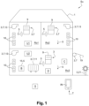
- a building 1 comprises, for example, three rooms Ro1, Ro2, Ro3. Building 1 also includes 3 home automation equipment and 5 sensors.
- Home automation equipment 3 can be an actuator arranged to move or adjust an element of the building 1, for example an actuator 7 to move a roller shutter 9 or a terrace awning 19, or a regulation system 10 for a heating 11 or a system ventilation 13.
- Home automation equipment 3 can also be lighting, for example outdoor terrace lighting 21 or a lighting control system, an alarm system, or even a video camera, in particular a video surveillance camera.
- the home automation system Su can also include a control point 15 of an actuator 7, such as a wireless control box B for the roller shutter 9.
- the home automation installation Su can comprise one or more sensors 5, integrated with an actuator 7, with a control point 15 or even with the control unit B, or independently with these elements.
- a sensor 5 can, in particular, be arranged to measure a physical quantity, for example a temperature sensor, an insolation sensor or a humidity sensor.
- Position sensors 5 of home automation equipment 3 of the building 1, such as, for example, sensors of the opening state of a roller shutter 9 or position sensors of an opening such as a window, motorized or not can also be provided.
- the home automation installation may also include one or more presence sensors.
- a home automation equipment 3 and a sensor 5 are thus to be considered as units having available information on the real observed states of elements of the building 1 and being capable of sharing this information with other elements of the home automation installation Su.
- the home automation equipment 3 and the sensors 5 can thus have access to any measurable physical quantity, such as the temperature of each room Ro1, Ro2, Ro3 or a state of an element of the building 1, such as the opening state of a roller shutter 9, the status of an alarm, etc.
- home automation device or device D interchangeably to designate sensors or home automation equipment, or parts of home automation equipment 3 or sensors 5.
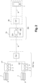
- the home automation installation Su comprises a plurality of central control units U1, U2.
- central control units U1, U2 are represented on the figure 1 .
- a home automation installation can also comprise a single central control unit.
- Each central control unit U1, U2 is arranged to control and/or control part of the devices D of the installation Su forming a group DGrU1, DGrU2.
- the central control unit U1 is in charge of the devices D arranged in rooms Ro1 and Ro2 on the first floor of the building, while the central control unit U2 is in charge of the devices D arranged in room Ro3 on the ground floor. floor of the building and exterior features.
- each central control unit U1, U2 is arranged to combine all of the data coming from the devices D of its group DGrU1, DGrU2 and to process this data.
- each central control unit U is arranged to communicate with a server Sv.
- the central control units U1, U2 are arranged on a private network PN, access to which is generally protected by a firewall FW.
- the server Sv is also placed on a private network SN.
- the private network PN is linked to an extended network N, for example the Internet.
- the server Sv is arranged to communicate with a set of such central control units U. We will describe one of these units hereafter.
- a central control unit U comprises a processing unit 2 arranged to contain and execute a first computer program.
- the processing unit 2 comprises a processor, a storage flash memory as well as a random access memory, and an Ethernet chip.
- the central control unit U further comprises at least one communication module 2' intended for controlling and/or controlling home automation equipment 3 and/or sensors 5, the home automation equipment 3 possibly being actuators 7 , lights 21, an alarm system, or a video camera.
- the communication module 2' allows the control and command of at least one actuator 7, of a mobile element of the building 1, such as for example a roller shutter 9, or an adjustable sunscreen 9' or other actuators 7 or lights 21, as previously described with reference to the figure 1 , according to the first local communication protocol P1.
- a mobile element of the building 1 such as for example a roller shutter 9, or an adjustable sunscreen 9' or other actuators 7 or lights 21, as previously described with reference to the figure 1 , according to the first local communication protocol P1.
- the communication module 2' can be arranged to implement, for example, one or more of the first local protocols P1, for example of the Z-Wave, EnOcean, IO Homecontrol, Somfy RTS, KNX, MODBUS, Wavenis type. , Philips HUE.
- These local protocols are generally non-IP local communication protocols.
- the central control unit can be integrated into the home automation device.
- the unit control center is integrated into a router and/or a modem making a connection to a wide area network, in particular to the Internet.
- the central unit U can allow the control and/or the command of an alarm system.
- Each central control unit U further comprises a communication module 4 with the server Sv according to a third communication protocol P3.
- the server Sv allows command and/or remote control and comprises one or more processing units 102 arranged to contain and execute a second computer program.
- a central control unit U can communicate with the server Sv through an intermediate server Sv′, for example of a third-party service provider, whose intermediate server offers a service interface or API.
- the server Sv comprises, for its part, at least one communication interface 104 intended for communication with the central unit U.
- the server Sv can also include a communication interface 106 intended for communication with a command and/or control interface IN allowing a user to remotely control the home automation installation.
- server is a logical designation which may cover the use of several physical servers to distribute the computing processing load to be carried out.
- the command and/or control interface IN comprises, for example, a web server 107 and a mobile communication terminal T communicating via the wide area network N.
- the mobile communication terminal T can be, for example, a smart telephone or a tablet.
- the mobile communication terminal T can be the same or a terminal of the same type as that with which the central control unit U communicates locally by means of the communication module 4' as we will detail later, or a different terminal. We will designate these mobile terminals interchangeably by the reference T.
- the command and/or control interface IN comprises a processor which can be placed at the level of the web server 107 and/or of the mobile communication terminal T.
- the processor of the command and/or control interface IN is arranged to use a third computer program.
- This third computer program is for its part arranged to execute a downloadable application.
- the mobile communication terminal T comprises a data input device and a display device, for example in the form of a touch control part of a screen of the terminal T and in the form of one or more buttons of the T terminal.
- THE figure 1 And 2 describe an installation Su which comprises a set of devices D and a plurality of central control units U1, U2, arranged in the same dwelling, the same building or the same physical location.
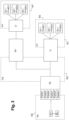
- home automation devices D1, D2, Dn belong to a local network R1 managed by a central control unit U within the home automation installation and communicate according to a first local communication protocol P1 with the central control unit U.
- devices D1, D2, Dn have a location identifier consisting of a local address P1AD1, P1AD2, P1ADn in this network.
- the logical devices D1, D2, Dn can be modeled as nodes or endpoints in the local network.
- a second group of home automation devices D1', D2', Dn' is represented which belongs to a local network R1' managed by a central control unit U' within a second home automation installation and communicate according to a first local communication protocol P1' with the central control unit U'.
- the devices D1′, D2′, Dn′ have a location identifier consisting of a local address P1AD1′, P1AD2′, P1ADn′ in this network.
- the central unit U' communicates with the server Sv through an intermediate server Sv'.
- the central control unit communicates with the server Sv by a third communication protocol P3 on a third network R3.
- the intermediate server Sv′ also communicates via the network R3.
- a network R2 corresponds to a second extended network R2 on which communication can be carried out by a second protocol P2.
- the Server Sv is connected to this extended network, as well as user terminals T, control points or other home automation devices which can be modeled by nodes N belonging to the second network R2 and communicating according to a second target communication protocol P2, in particular according to a protocol using the IP protocol.
- node is meant equipment present on a network R2 using the second communication protocol P2 and which has a unique location identifier on the network R2.
- the server or management unit Sv is arranged to present to the nodes N1, Nk of the network R2 communicating according to the network R2 a set of location identifiers P2AD1, P2AD2, P2ADn according to the second target communication protocol P2 for the devices communicating according to the first local communication protocol P1 and can offer a home automation device discovery interface D1, D2, Dn detailing the type, functions and/or state variables of the devices, according to the second communication protocol P2.
- the configuration process can be triggered by the reception of a message Mlnit received by the management unit Sv coming from a user terminal Usr/T which sends it in a step EcfT1.
- the management unit Sv sends discovery messages MD to the central control unit to which each device D1, D2 is attached according to the third communication protocol P3, this message MD being received respectively in steps EcfD12 or ECfD22.
- pressing a button of the central control unit U can also allow the triggering of the method.
- the configuration message is received by the management unit from the central control unit U.
- an action on a home automation device D such as pressing a button can be considered as triggering event.
- the configuration message is received by the management unit Sv coming from the central control unit U, the unit control center receiving the message from the home automation device D according to the first communication protocol P1. It can be considered in these cases that the method begins at the step of receiving a configuration message described below.
- the management unit Sv receives configuration messages MCfD1, MCfD2 from the central control unit to which each device D1, D2 is attached which sends these messages respectively in steps ECfD12 and ECfD22.
- the unique identifier DURL can be contained in the configuration message or can be determined upon receipt of this message.
- the management unit Sv obtains a location identifier P2AD1, P2AD2 for each home automation device D1, D2 according to a second target communication protocol P2.
- the methods for obtaining the location identifier can be multiple and are detailed later.
- the management unit can verify the existence of at least one function conversion rule RCFX arranged to convert the definition of the at least one function P1F1D1, P1F2D1, P1F1D2, P1F2D2 according to the first communication protocol P1 into at least one definition of a function P2F1D1, P2F2D1, P2F1D2, P2F2D2 according to the second target communication protocol P2 and/or of a state conversion rule RCSX arranged to convert the definition of the at least one state variable P1S1D1, P1S2D1, P1S1D2, P1S2D2 according to the first communication protocol P1 in at least one definition a state variable P2S1D1, P2S2D1, P2S1D2, P2S2D2 according to the second target communication protocol P2.
- RCFX arranged to convert the definition of the at least one function P1F1D1, P1F2D1, P1F1D2, P1F2D2 according to the first communication protocol P1 into at least
- This verification can be based on the type of device P2TD1, P2TD2, or on the definitions of functions, groups of functions and/or on the definitions of state variables or groups of state variables. Indeed, depending on the protocols used, a type may suffice to identify the functions or state variables supported, as for example in the IO homecontrol protocol, or functions or groups of functions or variables or groups of state variables must be listed, as for example in the Zwave protocol.
- the management unit Sv can identify a correspondence between a type P1TD1, P1TD2 of home automation device according to the first local communication protocol P1 and a type P2TD1, P2TD2 of home automation device according to the second local communication protocol P2.
- the conversion rules can be stored in one or more correspondence tables, included in a knowledge base.
- the management unit Sv can obtain it, for example by downloading from a third-party server.
- the conversion rule(s) can then be saved in an EcfSv6 step.
- the implementation of the conversion of a function can also comprise a step of defining an action to be carried out at least partially by the management unit Sv or the central control unit U in correspondence with a function according to the second protocol corresponding to a location identifier, or the limitation of the requested function or the prohibition of a function to be performed.
- the corresponding definitions can be predefined in the correspondence table or knowledge base.
- the conversion of the functions or state variables can alternatively be implemented within the framework of the control and/or supervision method.
- the management unit Sv records the correspondence between the unique home automation device identifier DURL of the at least one home automation device D1, D2 according to the first communication protocol and the location identifier P2AD1, P2AD2 of the at least one home automation device D1, D2 according to the second communication protocol P2 in a table of nodes illustrated in figure 6 ;
- the home automation device D1 is virtualized.
- the management unit Sv can act on behalf of D1 on the network R2.
- a group of devices can be identified by the same location identifier according to the second protocol.
- the correspondence table comprises in this case several location identifiers according to the first communication protocol which correspond to the same location identifier according to the second communication protocol.
- the method comprises a plurality of steps for receiving configuration messages corresponding to a plurality of first communication protocols.
- the method comprises a plurality of discovery message transmission steps according to a plurality of first communication protocols.
- the method comprises a plurality of correspondence between a device communicating according to the first communication protocol and location identifiers according to several second control methods.
- the management unit Sv may be necessary for the management unit Sv to send a registration message MI in a step ECfSv5' in order to subscribe to notifications relating to at at least one state variable of at least one home automation device D1, D2, the central control unit to which the home automation devices receiving this message are attached respectively in steps EcfD15', EcfD25'.
- notifications concerning the state variables will be communicated to the management unit within the framework of a supervision process.
- location identifier an address in a proprietary format corresponding to the home automation protocol used.
- a location identifier may in particular be a network address, such as for example an IPv4 or IPv6 address, or even a composition of a network address and a resource identifier indicated by a path of access, for example in the form of the following URL: ⁇ protocol>:// ⁇ host address>[: ⁇ port>]/ ⁇ resource path>
- the location identifier corresponds respectively to a network address or to a combination of a network address and a resource.
- the second target communication protocol involves the use of distinct network addresses for the home automation devices.
- the location identifier corresponds in this case to a network address.
- the network address is chosen from a block of free addresses assigned to the Server Sv.
- a prefix is associated with the communication interface of the Server Sv on the network R2 , the rest of the address (suffix) being left to the discretion of the Server Sv.
- this prefix can define a block of global unicast addresses and must be obtained beforehand from from an approved supplier.
- the network address is equal to, or contains the physical address of the device, as for example in the case of an IPv6 protocol used in Link-local mode.
- the management unit Sv determines a unique physical address for the device D1 to be emulated.
- the management unit Sv can choose a MAC address from a range previously acquired from the IEEE registration body, the address corresponding to a composition : Company_id + free suffix
- the management unit Sv determines a unique network address from the physical address.
- the network address is obtained by applying an injective transformation from the physical address, as for example in the case of the IPv6 Link-local protocol, in which the network address is constructed from the MAC address.
- the network address is obtained from a network controller on presentation of a physical address.
- this may be the case in a protocol above IP.
- the management unit determines a unique physical address for the device D1 to be emulated, similarly to the first possibility mentioned.
- the unit of management Sv obtains a unique network address on the R2 network from a network controller based on the physical address.
- the network controller can be a DHCP Server for IPv4 or IPv6.
- the network address can be pooled for several home automation devices D1, D2.
- the location identifier corresponds to a composition of a network address and a resource identifier indicated by an access path. In this case, it may be sufficient to obtain a network address for the management unit Sv.
- the /light/1 resource is assigned to the first light-type device.
- the /light/2 resource is assigned to the second light-type device.
- the management unit Sv and the central control units U can use a unique identifier DURL to identify the home automation devices.
- the structure of a unique identifier of a DURL home automation device will now be described corresponding to a particular embodiment.
- the form of the unique identifier of a DURL device can be the following: ⁇ protocol>:// ⁇ gatewayld>/ ⁇ rawDeviceAddress>(# ⁇ subsystemld>)
- This unique identifier DURL corresponds to a device D communicating via the KNX protocol with an individual address 1.1.3 accessible by the central control unit U bearing the identifier #0201-0001-1234.
- This unique identifier DURL corresponds to a subsystem bearing the n°2 associated with a device D communicating by the IO homecontrol protocol with a radio address 145036 accessible by the central control unit U bearing the identifier #0201-0001-1234 .
- the step of obtaining the location identifier can correspond to a reception of an entry by the user of a location identifier according to the second communication protocol as shown in the figure 4 by step ECfSv2'.
- the step of receiving a configuration message comprises a declaration by the user of the location identifier according to the first communication protocol and/or a declaration by the user of at least one function or of a type of device according to the first communication protocol as shown in the figure 4 by step ECfSv2'.
- the method is executed by the management unit Sv. Only two nodes N1, Nk communicating according to the second target communication protocol P2 on the network R2 are represented on the figure 7 . However, a single node or a number greater than two nodes can also be considered.
- the management unit Sv receives a discovery message MD according to the second communication protocol P2 transmitted by a node N1 in a step EDN11.
- the discovery message EDN11 can include a filtering criterion based for example on a location identifier or a group of location identifiers or even on the basis of information relating to an installation Su and/or to an account of a Usr user and/or to a type of product.
- the discovery message EDN11 can be addressed to a location identifier or specific address on the management unit Sv corresponding to a location identifier of a register.
- a publication of a location identifier according to the second target communication protocol is carried out for home automation devices D1, D2 which are only capable of communicating according to a local or proprietary protocol.
- the management unit Sv can periodically check the availability of the home automation devices and only send description and/or existence declaration messages in the event of the availability of the home automation device concerned.
- the control method is executed by the management unit Sv. Only a node N1 communicating according to the second target communication protocol P2 on the network R2 is represented on the figure 8 . However, a single node or a number greater than two nodes can also be considered. In the same way, only a home automation device D1 communicating, via a central unit of command U according to the first local protocol P1 is represented but other devices may be present.
- a connection can be established between the node between a node N1 communicating according to the second communication protocol P2 and the management unit Sv, the management unit Sv acting on the network R2 as a representative virtual home automation devices of the network R1 communicating, via a central control unit U according to the first local communication protocol P1.
- the management unit Sv receives at least one command message P2MC originating from a node N1 communicating according to the second communication protocol P2.
- the command message P2MC which is transmitted by the node N1 in a step ECN11 comprises at least one location identifier P2AD1 of a home automation device D1 according to the second target communication protocol P2 and at least one definition of a function P2F1D1 of the device home automation D1 according to the second communication protocol P2.
- the device concerned by the command is the device D1 identified by the location identifier P2AD1, that the function concerned is a function P2F1D1 intended for this single home automation device.
- the management unit Sv determines a unique home automation device identifier DURL corresponding to the location identifier P2AD1 of the at least one home automation device D1 according to the second communication protocol P2 received in the command message P2MC .
- the management unit Sv applies a function conversion rule RCFX arranged to convert the definition of the function P2F1D1 according to the second target communication protocol P2 into at least one definition of a function P1F1D1 according to the first protocol P1 local communication device.
- the management unit Sv can use the correspondence table filled in during the configuration process.
- the step of applying a conversion rule can include performing additional processing steps when calling the command, in particular if part of the function cannot be performed on the home automation device, and in particular a partial enrichment of the function, or even the limitation of the function requested or the prohibition of a function to be performed.
- a planning of an order can be provided if the device itself does not allow such planning.
- a parameter conversion can be performed by the central control unit.
- the management unit Sv sends at least one control message P3MC according to the third communication protocol P3 to the central control unit U to which is attached the at least one home automation device D1 corresponding to the unique home automation device identifier DURL and to the function P1F1D1 according to the first local communication protocol P1 which receives it in a step ECU4.
- the central control unit formats and sends a message P1MC by repeating the elements contained in the message P3MC to the home automation device D1 according to the first control protocol P1.
- the message P1MC is received in a step ECD15.
- the home automation device D1 executes the function P1F1D1.
- the home automation device D1 sends a command return message RP1MC according to the first communication protocol P1 to the central control unit U which receives it in a step ECU7.
- the message contains control return information P1RC expressed according to the first local communication protocol P1.
- step ECU8 the central control unit U sends a command return message RP3MC according to the third communication protocol P3 to the management unit Sv which receives it in a step ECSv8.
- This message contains the P1RC command return information expressed according to the first local communication protocol P1.
- the management unit Sv applies, if necessary, a function conversion rule RCFX in order to convert command feedback information P1RC expressed according to the first local communication protocol P1 into command feedback information P2RC expressed according to the second target communication protocol P2.
- the management unit Sv sends at least one command return message RP2MC to the node N1 comprising command return information P2RC according to the second target communication protocol P2.
- the management unit Sv can receive a command message P2MC corresponding to a grouped command intended for a set of home automation devices identified by a set of location identifiers.
- a plurality of control messages P1MC are sent to the control devices concerned, after conversion of the function concerned and the location identification for each device.
- the management unit can optionally aggregate the results or feedback communicated by the home automation devices D so as to return a single P2RC command feedback message.
- it may be agreed that the command is deemed to have been carried out successfully if all the executions of individual functions have a positive return, or failed if one of the functions for a home automation device returns a failure value.
- a group of devices can be identified by the same location identifier according to the second protocol.
- the correspondence table comprises in this case several unique identifiers of home automation device according to the first communication protocol which correspond to the same location identifier according to the second communication protocol. In this case, it is possible to proceed as previously mentioned for the grouped order.
- a plurality of functions according to the first communication protocol is sent to the devices concerned corresponding to the plurality of location identifiers according to the first communication protocol, then the returns are stored and then aggregated to return a single result for the command message considered.
- the supervision method is executed by the management unit Sv. Only a node N1 communicating according to the second target communication protocol P2 on the network R2 is represented on the figure 9 . However, a single node or a number greater than two nodes can also be considered. Likewise, only one home automation device D1 communicating, via a central control unit U, according to the first local protocol P1 is shown but other devices may be present.
- the management unit Sv receives a supervision message P3MS according to the third communication protocol P3 transmitted by a central control unit U to which a home automation device D1 is attached in a step ESU4.
- the supervision message P3MS comprising information relating to a value of at least one state variable P1S1D1 of the at least one home automation device D1 according to the first communication protocol P1.
- the step ESSv2 can be successive to a first step ESSv1 of sending an interrogation or polling message, received by the central control unit U to which the home automation device D1 is attached in a step ESU1.
- the sending of a P1MS message can be initiated by the home automation device D1 in a step ESD13 or the central control unit U autonomously, for example by detecting an event modifying the value of a state variable P1S1D1.
- a step ESU2 of sending an interrogation or polling message can also be implemented by the central control unit U intended for the home automation device D in order to identify, for example, a change in the value of a variable status P1S1D1.
- the sending of the P1MS message can be carried out indiscriminately to a set of nodes present on the network communicating according to the first communication protocol. This arrangement corresponds to so-called “Broadcast” mode.
- the home automation device can send the supervision message only to the nodes registered on the network established according to the first communication protocol, and in particular to the central control unit U if the latter is registered .
- the central control unit U performs a prior step of sending, to the home automation device D1, a request for registration in a subscription list to an event relating to at least one variable d status P1S1D1 of home automation device D1.
- the management unit Sv applies a state conversion rule RCSX in order to convert the at least one item of information relating to a value of at least one state variable P1S1D1 of the at least one device home automation D1 expressed according to the first local communication protocol P1 in a value of at least one state variable P2S1D1 of the home automation device D1 expressed according to the second target communication protocol P2.
- a step ESSv6 the management unit Sv determines a location identifier P2AD1 of the home automation device P2AD1 according to the second protocol of communication P2 on the basis of the unique identifier DURL of home automation device D1 contained in the message P3MS or determinable on the basis of identification elements contained in this message.
- the steps the steps ESSv5 and ESSv6 of applying a conversion rule and determining the address or identifier can be carried out sequentially in any order or simultaneously.
- the management unit Sv sends a P2MS supervision message to the node N1 communicating according to a second communication protocol P2, the P2MS supervision message comprising information relating to a value of at least one variable d state P2S1D1 of the home automation device D1 according to the second target communication protocol P2 and being related to the location identifier P2AD1 of the home automation device D1 according to the second communication protocol P2.
- the sending of the P2MS supervision message can be carried out on the initiative of the management unit Sv spontaneously or following the reception of a P3MS supervision message from a central control unit U to which a home automation device D1 is attached.
- the supervision message P2MS can be sent following the reception by the management unit Sv in a step ESSv5 of an MQ request message transmitted in a step ESN15 coming from a node N1 of the extended network R2.
- the management unit Sv comprises a storage space or base for the values of state variables for the home automation devices attached to it.
- the sending of the P2MS supervision message can be carried out indiscriminately to a set of nodes present on the network communicating according to the second communication protocol P2.
- This arrangement corresponds to a so-called “Broadcast” broadcasting mode.
- the central control unit can send the supervision message only to the nodes of the network R2 registered in a subscription list, and in particular to the node N1.
- the node N1 performs a prior step of sending to the management unit Sv a request for registration in a subscription list to an event relating to at least one state variable P2S1D1 of the home automation device D1.
- the supervision method can be adapted to a control point.
- the command is identified and is notified to the management unit as a modification of a state variable.
- the polling step ESSv1 mentioned previously makes it possible to implement an event mode emulation for a device or a central control unit U not offering such functionality, in which the management unit Sv can consult periodically the values of state variables of the devices via a central control unit U, detecting the modifications of values of state variables by comparing the last value obtained and the data or data that it has previously stored and sending, in the event of a modification, a P2MS supervision message relating to the modified state variable intended for a node N1 subscribed to the modifications of this state variable.
- a home automation device D1 of the temperature sensor type is considered.
- This sensor communicates according to a first local protocol P1 of the IO-homecontrol type and is intended to be made accessible as a sensor according to the second communication protocol P2 using an application layer of the OIC/lotivity type and a transport layer of the CoAP type on IPv6 by the management unit Sv.
- the configuration method can be implemented as follows.
- the home automation device D is described as an IO system sensor of type 0x03 (outside temperature sensor, unit: °K) with a location identifier according to the first protocol P1 in the form of an IO network address 0x485670.
- the central control unit U registers with the home automation device D (IO sensor) to receive events relating to the variation in the measured temperature, which corresponds to a state variable P1S1 of the device.
- the central control unit U then proceeds to the transmission according to the third communication protocol P3 of this information to the management unit Sv, which corresponds to a step ECfD13, in particular the location identifier P1AD1 of this device according to the protocol P1 and the type of device D1.
- the management unit Sv then proceeds to the automatic determination of a standard lotivity type or profile to be used to publish this device by using a correspondence table according to the protocol P1 and the type of product in order to determine a conversion rule in an ECfv6 stage.
- the management unit Sv then proceeds to determine a location identifier P2AD1 according to the protocol P2, in this case a free IPv6 address for the device, corresponding to step ECfsv5.
- this network address can be chosen arbitrarily in an IPv6 prefix pre-assigned to the management unit.
- the management unit Sv chooses to assign the IPv6 address 2001:0db8:3c4d:0015:0000:0000:abcd:ef13 to represent the home automation device D1 in the form of an "avatar" on the network R2 .
- the management unit Sv proceeds in a step ECfsv7 to recording the correspondence of the type of device according to the first and the second protocol P2 and of a unique device identifier DURL in the table of nodes.
- a discovery method can then be implemented if the second protocol P2 allows it. Otherwise (for example in the case of an IPv6 address published on the Internet), the address P2AD1 chosen for the avatar of the device D1 can be published in a name registry or through a search API which will allow the user to read this address.
- the supervision or control method can then be implemented.
- the central control unit U sends the information back by sending a message P3MS according to the third communication protocol P3 in a step ESU4 to the management unit Sv which receives it in a step ESSv4 and will determine the corresponding location identifier according to the second communication protocol P2 using the table of nodes in a step ESSv6.
- the management unit Sv determines whether the temperature state variable P1S1D1 has a match in the lotivity profile associated with the virtual device and the possible conversion function.
- the state variable temperature in degrees Kelvin of the home automation device D1 can be adapted to a notification attached to the state variable P2S1D1 representing the temperature in degrees Celsius.
- the management unit Sv applies the following conversion function which corresponds to a conversion into degrees Celsius and into an integer value with a precision of 0.01: T ⁇ > floor T ⁇ 273.15 * 100 .
- the management unit Sv can then keep this value in order to be able to respond to a subsequent request on the second protocol P2, for example a CoAP request of the "GET” type or send a P2MS supervision message to any customers who have subscribed to the prior to the events of the device D1 by a CoAP request of the “OBSERVE” type, in the form of a CoAP notification message to the connected node N1 containing the new temperature value P2S1D1 in a step ESSv7.
- a CoAP request of the "GET” type or send a P2MS supervision message to any customers who have subscribed to the prior to the events of the device D1 by a CoAP request of the “OBSERVE” type, in the form of a CoAP notification message to the connected node N1 containing the new temperature value P2S1D1 in a step ESSv7.
- an active reading of the temperature can be carried out.
- the node N1 which is a lotivity client sends a read request to the management unit Sv concerning the “Temperature” state variable or characteristic of the virtual device, in a step ESN11.
- the command message P2MC transmitted by the node N1 comprises a location identifier P2AD1 of a home automation device D1 according to the second target communication protocol P2 and a definition of a function P2F1D1 of the home automation device D1 corresponding to an interrogation of the temperature variable according to the second communication protocol P2.
- the management unit Sv determines a unique identifier DURL of the home automation device D1 corresponding to the location identifier P2AD1 of the at least one home automation device D1 according to the second communication protocol P2 received in the command message P2MC.
- the management unit Sv applies a function conversion rule RCFX arranged to convert the definition of the function P2F1D1 according to the second target communication protocol P2 into at least one definition of a function P1F1D1 according to the first protocol P1 local communication device.
- the management unit Sv can respond by using the last value received from the sensor IO or send a command to the device via the control unit U to obtain this value.
- the management unit Sv sends a command message P3MC according to the third communication protocol P3 to the central control unit U to which is attached the at least one home automation device D1 corresponding to the unique device identifier DURL and to the function P1F1D1 according to the first local communication protocol P1 which receives it in a step ECU4.
- the central control unit formats and sends a P1MC message by taking over the elements contained in the P3MC message to the home automation device D1 according to the first control protocol P1.
- the message P1MC is received in a step ECD15.
- the home automation device D1 executes the function P1F1D1 and in this case returns a temperature value.
- the home automation device D1 sends a command return message RP1MC according to the first communication protocol P1 to the central control unit U which receives it in a step ECU7.
- the message contains P1RC control feedback information corresponding to the temperature.
- step ECU8 the central control unit U sends a command return message RP3MC according to the third communication protocol P3 to the management unit Sv which receives it in a step ECSv8.
- This message contains the P1RC command return information expressed according to the first local communication protocol P1.
- the management unit Sv applies a function conversion rule RCFX in order to convert command feedback information P1RC expressed according to the first local communication protocol P1 into command feedback information P2RC expressed according to the second target communication protocol P2.
- the management unit Sv sends at least one control return message RP2MC to the node N1 comprising control return information P2RC according to the second target communication protocol P2 which corresponds to the temperature.
- a home automation device D1 of micromodule type for Yokis roller shutter is considered.
- This home automation device D1 communicates according to a radio communication protocol P1 proprietary to the manufacturer.
- This home automation device can communicate with a central control unit U having a suitable transmitter/receiver. It is desired to publish an avatar of this device on a wide area network such as the Internet using the management unit Sv, using a second communication protocol P2 based on messages in JSON format in an MQTT encapsulation and a TCP transport over IPv6.
- the management unit Sv can be a server accessible on the Internet and the central control unit U can be a home automation box connected to the management unit by a TCP connection established in such a way permanently through the user's local network and its Internet gateway, for example an ADSL modem.
- the central control unit U obtains the unique address of the module according to the protocol P1, for example 0x2A370.
- this address and the type of the discovered device are transmitted by the central control unit U in the form of a JSON message which acts as a third protocol P3 to the management unit Sv which receives this message in an ECfSv3 step.
- the management unit Sv determines an IPv6 address available in a previously obtained block of addresses, for example the IPv6 address 2001:0db8:3c4d:0015:0000:0000:abcd:0644.
- the management unit records the correspondence between the device identifier DURL - consisting of the identifier of the control unit U, the address of D1 according to the P1 protocol - and the chosen IPv6 address in a correspondence table.
- the management unit also listens to this network address if necessary, in order to be able to receive messages intended for the avatar of the device.
- the management unit also saves a type of home automation device.
- a control application executed on a node N1 for example by another home automation device connected to the Internet, by a device or a command server, sends a command message P2MC to the IPv6 address of the avatar of the device D1 according to the protocol P2 which receives it in a step ECSv1.
- the command message can correspond for example to a request to open the roller shutter.
- the management unit Sv determines from the correspondence table established during the configuration phase an identification of the home automation device concerned by the unique identifier of the home automation device DURL.
- This identifier contains the identifier of the central control unit U which can control the device as well as the protocol P1, the type and the address of the device D1 according to this protocol.
- the management unit Sv converts the command to the format expected by the device D1 according to the first communication protocol P1, i.e. a command UP, then transmits in a step ECSv4 this information in the form of a command message P3MC to the central control unit U associated according to the third communication protocol P3, the central control unit receiving this message in a step ECU4.
- the central control unit U retransmits the order to the micromodule in the form of a control message P1MC using the first communication protocol P1, here the Yokis radio protocol, which receives this message in a step ECD15.
- step ECD16 the micromodule executes the command and sets the rolling shutter in motion upwards.
- step ECD17 the micromodule returns a confirmation message RP1MC indicating that it has indeed taken the command into account to the central control unit U, which receives it in a step ECU7.
- the central control unit U returns this information with the identifier of the device D1 to the management unit Sv in a message RP3MC according to the third protocol to the management unit Sv which receives it in a step ECSv8.
- the management unit Sv uses the correspondence table established during the configuration phase, converts the return code of the command, then in an ECSv10 step, sends back a message RP2MC on the network R2 using the source address P2AD1 and destined for the node N1, indicating that the command initiated by the node N1 has been correctly taken into account.
Landscapes
- Engineering & Computer Science (AREA)
- Automation & Control Theory (AREA)
- Computer Networks & Wireless Communication (AREA)
- Signal Processing (AREA)
- Computing Systems (AREA)
- Multimedia (AREA)
- Computer Security & Cryptography (AREA)
- Selective Calling Equipment (AREA)
- Small-Scale Networks (AREA)
- Computer And Data Communications (AREA)
- Communication Control (AREA)
Description
La présente invention concerne la domotique.The present invention relates to home automation.
Une installation domotique d'un bâtiment peut comprendre une pluralité de dispositifs domotiques. Il est connu de procéder à la configuration, et au contrôle, c'est à dire à la commande et/ou à la supervision de ladite installation en utilisant une unité centrale de commande qui communique avec un ou plusieurs dispositifs domotiques.A home automation installation of a building can comprise a plurality of home automation devices. It is known to carry out the configuration, and the control, that is to say the control and/or the supervision of said installation by using a central control unit which communicates with one or more home automation devices.
Dans une telle installation, les dispositifs domotiques sont disposés sur un réseau local et peuvent communiquer selon une pluralité de protocoles locaux, notamment des protocoles locaux de type protocole domotique, par exemple un protocole propriétaire n'utilisant pas un adressage IP, ou encore des protocoles de communication au dessus du protocole IP, ou un protocole point à point générique, par exemple Bluetooth.In such an installation, the home automation devices are arranged on a local network and can communicate according to a plurality of local protocols, in particular local protocols of the home automation protocol type, for example a proprietary protocol not using IP addressing, or alternatively protocols communication protocol above the IP protocol, or a generic point-to-point protocol, for example Bluetooth.
La présence de différents protocoles de communication ne permet pas une communication facile avec les dispositifs ou oblige à prévoir l'implémentation de plusieurs protocoles de communication pour permettre la communication avec ces dispositifs, ce qui augmente le coût et/ou la complexité de la programmation pour accéder à ces dispositifs.The presence of different communication protocols does not allow easy communication with the devices or makes it necessary to provide for the implementation of several communication protocols to allow communication with these devices, which increases the cost and/or the complexity of the programming for access these devices.
Par ailleurs, les dispositifs domotiques sont disposés sur un réseau local et ne sont pas accessibles aisément pour une communication, une commande ou une supervision par un dispositif ou un noeud distant, notamment par l'intermédiaire d'un réseau étendu.Furthermore, the home automation devices are placed on a local network and are not easily accessible for communication, control or supervision by a remote device or node, in particular via a wide area network.
La présente invention a pour but de résoudre tout ou partie des inconvénients mentionnés ci-dessus.The present invention aims to solve all or part of the drawbacks mentioned above.
"
L'invention est définie par les procédés des revendications indépendantes 1 et 2.The invention is defined by the methods of
A cet effet, la présente invention concerne un procédé de configuration d'une installation domotique comprenant au moins un dispositif domotique et au moins une unité centrale de commande, l'au moins un dispositif domotique étant susceptible de communiquer avec l'unité centrale de commande le procédé étant exécuté par une unité de gestion susceptible de communiquer avec l'au moins une unité centrale de commande par l'intermédiaire d'au moins un premier protocole ; le procédé comprenant les étapes suivantes :
- Réception, en provenance de l'unité centrale de commande, d'au moins un message de configuration relatif à au moins un dispositif domotique et à :
- ∘ un type de l'au moins un dispositif domotique ; et/ou
- ∘ au moins une définition d'une fonction ou d'un groupe de fonctions de l'au moins un dispositif domotique selon ledit premier protocole de communication et/ou
- ∘ au moins une définition d'une variable d'état ou d'un groupe de variables d'états de l'au moins un dispositif domotique selon ledit premier protocole de communication ;
- Obtention d'un identifiant de localisation de l'au moins un dispositif domotique selon un second protocole de communication cible ;
- Enregistrement de la correspondance entre l'identifiant de localisation de l'au moins un dispositif domotique selon le second protocole de communication et d'au moins un élément d'identification contenu dans le message de configuration ou déterminable à réception du message de configuration dont le contenu ou la combinaison permet une identification unique d'un dispositif domotique ;
- Enregistrement de l'au moins un type de l'au moins un dispositif domotique ; et/ou de l'au moins une définition d'une fonction ou d'un groupe de fonctions de l'au moins un dispositif domotique et/ou de l'au moins une définition d'une variable d'état ou d'un groupe de variables d'états de l'au moins un dispositif domotique ; et/ou d'une règle de conversion de fonction agencée pour convertir la définition de l'au moins une fonction ou groupe de fonction selon le premier protocole de communication en au moins une définition d'une fonction ou d'un groupe de fonction selon le second protocole de communication cible et/ou d'une règle de conversion d'état agencée pour convertir la définition de l'au moins une variable d'état selon le premier protocole de communication en au moins une définition d'une variable d'état selon le second protocole de communication cible.
- Reception, from the central control unit, of at least one configuration message relating to at least one home automation device and to:
- ∘ a type of the at least one home automation device; and or
- ∘ at least one definition of a function or a group of functions of the at least one home automation device according to said first communication protocol and/or
- ∘ at least one definition of a state variable or of a group of state variables of the at least one home automation device according to said first communication protocol;
- Obtaining a location identifier of the at least one home automation device according to a second target communication protocol;
- Recording of the correspondence between the location identifier of the at least one home automation device according to the second communication protocol and of at least one identification element contained in the configuration message or determinable on receipt of the configuration message whose content or combination allows unique identification of a home automation device;
- Recording of the at least one type of the at least one home automation device; and/or of the at least one definition of a function or of a group of functions of the at least one home automation device and/or of the at least one definition of a state variable or of a group of state variables of the at least one home automation device; and/or a function conversion rule arranged to convert the definition of the at least one function or function group according to the first communication protocol into at least one definition of a function or of a function group according to the second target communication protocol and/or of a state conversion rule arranged to convert the definition of the at least one state variable according to the first communication protocol into at least least one definition of a state variable according to the second target communication protocol.
Grâce aux dispositions selon l'invention, il est possible de mettre en place une publication d'un identifiant de localisation, selon le second protocole cible de communication pour des dispositif domotiques qui ne sont capables de communiquer que selon un protocole local ou propriétaire, sans avoir à apporter de modifications sur cet au moins un dispositif, ni sur l'unité centrale de commande à laquelle le dispositif est rattaché, et ainsi de mettre en relation cet au moins un dispositif avec d'autres noeuds d'un réseau étendu défini selon le second protocole de communication.Thanks to the provisions according to the invention, it is possible to set up a publication of a location identifier, according to the second target communication protocol for home automation devices which are only capable of communicating according to a local or proprietary protocol, without having to make modifications to this at least one device, nor to the central control unit to which the device is attached, and thus to connect this at least one device with other nodes of an extended network defined according to the second communication protocol.
Une fois les étapes du procédé de configuration réalisées, le dispositif domotique est virtualisé. L'unité de gestion peut agir pour le compte du dispositif domotique sur le réseau selon le deuxième protocole de communication.Once the steps of the configuration method have been completed, the home automation device is virtualized. The management unit can act on behalf of the home automation device on the network according to the second communication protocol.
Il est ainsi possible de présenter des fonctions/commandes ou des variables d'état de l'au moins un dispositif pour un contrôle selon le second protocole. Les fonctions/commande peuvent être traduites entre le premier protocole de communication et le second protocole de communication par les règles de conversion. La définition de l'au moins une fonction ou de l'au moins une variable d'état peut être explicite ou déterminée à partir d'au moins une définition d'un type selon ledit premier protocole de communication de l'au moins un dispositif domotique qui peut être déterminé à partir du message de configuration ou à partir d'un groupe de fonctions connu selon le protocole considéré (« function cluster »).It is thus possible to present functions/commands or state variables of the at least one device for control according to the second protocol. The functions/command can be translated between the first communication protocol and the second communication protocol by the conversion rules. The definition of the at least one function or of the at least one state variable can be explicit or determined from at least one definition of a type according to said first communication protocol of the at least one device home automation which can be determined from the configuration message or from a group of functions known according to the protocol considered (“function cluster”).
Selon une possibilité, chaque dispositif domotique est identifié par un identifiant de localisation, comme s'il pouvait lui-même assurer une communication. Plusieurs dispositifs distincts ont donc des identifiants de localisation distincts selon le deuxième protocole. L'unité de gestion reçoit les messages adressés à ces identifiants et est en mesure d'en assurer le traitement et/ou le routage jusqu'à l'unité centrale de commande à laquelle est rattachée le dispositif, en utilisant les règles de conversion pour communiquer un message converti selon le premier protocole.According to one possibility, each home automation device is identified by a location identifier, as if it could itself ensure a communication. Several distinct devices therefore have distinct location identifiers according to the second protocol. The management unit receives the messages addressed to these identifiers and is able to process and/or route them to the central control unit to which the device is attached, using the conversion rules for communicating a converted message according to the first protocol.
Selon une autre possibilité, un groupe de dispositif est identifié par un même identifiant selon le deuxième protocole. Ces dispositions permettent d'envisager une configuration d'un groupe de dispositif commandable comme un seul dispositif, de façon performante par un seul appel de fonction.According to another possibility, a group of devices is identified by the same identifier according to the second protocol. These provisions allow to consider a configuration of a group of controllable device as a single device, in a performing way by a single function call.
Selon une variante, le procédé comprend une pluralité de correspondance entre un dispositif communiquant selon le premier protocole de communication et des identifiants de localisation selon plusieurs deuxièmes procédés de commande. Ces dispositions permettent de virtualiser le dispositif pour le faire communiquer selon plusieurs deuxièmes protocoles cibles.According to a variant, the method comprises a plurality of correspondence between a device communicating according to the first communication protocol and location identifiers according to several second control methods. These provisions make it possible to virtualize the device in order to make it communicate according to several second target protocols.
Selon une variante, l'unité de gestion envoie un message d'inscription à destination d'un dispositif domotique ou à destination d'une unité centrale de commande à laquelle un dispositif est rattaché afin de s'abonner à des notifications relatives à au moins une variable d'état d'au moins un dispositif domotique. Ainsi des notifications concernant les variables d'état seront communiquées à l'unité de gestion dans le cadre d'un procédé de supervision.According to a variant, the management unit sends a registration message to a home automation device or to a central control unit to which a device is attached in order to subscribe to notifications relating to at least a state variable of at least one home automation device. Thus notifications concerning the state variables will be communicated to the management unit within the framework of a supervision process.
Selon un mode de mise en oeuvre, le procédé comprend une détermination d'une clef d'indexation sur la base d'éléments d'identification contenus dans le message de configuration ou déterminables à réception du message dont la combinaison permet une identification unique d'un dispositif domotique.According to one mode of implementation, the method comprises a determination of an indexing key on the basis of identification elements contained in the configuration message or determinable upon receipt of the message, the combination of which allows a unique identification of a home automation device.
L'identification est unique sur l'ensemble des dispositifs domotiques pouvant faire l'objet d'un accès par l'unité de gestion.The identification is unique for all the home automation devices that can be accessed by the management unit.
Selon un mode de mise en oeuvre, les différents éléments d'identification, pris individuellement, ne sont pas nécessairement uniques pour chaque dispositif ; mais la combinaison de deux ou plusieurs éléments d'information doit l'être. L'identifiant de l'unité centrale de commande à laquelle le dispositif domotique est rattaché ou l'adresse du dispositif domotique, ou éventuellement celle de son parent dans un système d'adressage hiérarchique dans le réseau local géré par l'unité centrale de commande sont des exemples d'éléments d'identification.According to one embodiment, the various identification elements, taken individually, are not necessarily unique for each device; but the combination of two or more pieces of information must be. The identifier of the central control unit to which the home automation device is attached or the address of the home automation device, or possibly that of its parent in a hierarchical addressing system in the local network managed by the central control unit are examples of identifiers.
Selon un mode de mise en oeuvre, un identifiant unique de dispositif peut être défini, cet identifiant pouvant utiliser notamment une notation d'adresse indépendante du protocole, par exemple selon un format de type URL.According to one mode of implementation, a unique device identifier can be defined, this identifier being able in particular to use an address notation independent of the protocol, for example according to a format of the URL type.
Selon un mode de mise en oeuvre, l'identifiant unique de dispositif comprend une adresse logique de dispositif.According to one mode of implementation, the unique device identifier comprises a logical device address.
Selon un mode de mise en oeuvre, l'adresse logique de dispositif comprend :
- un type protocole de communication du dispositif;
- un chemin de communication vers le dispositif.
- a communication protocol type of the device;
- a communication path to the device.
Selon un mode de mise en oeuvre, le chemin de communication vers le dispositif inclut les éventuelles unités centrales de commande intermédiaires et les adresses de terminaison ou identifiant de localisation à traverser, organisées de préférence selon une topologie hiérarchique.According to one mode of implementation, the communication path to the device includes any intermediate central control units and the termination addresses or location identifiers to be crossed, preferably organized according to a hierarchical topology.
Selon un mode de mise en oeuvre, l'adresse logique de dispositif comprend en outre un identifiant de sous-système si des sous-systèmes ou sous-ensembles du dispositif peuvent être définis.According to one mode of implementation, the logical device address also comprises a subsystem identifier if subsystems or subassemblies of the device can be defined.
Au sens de la présente invention, un troisième protocole est un protocole de communication utilisé pour la communication entre l'unité de gestion et au moins une unité centrale de commande, un troisième protocole est par exemple un protocole de communication au dessus du protocole IP et/ou un protocole générique permettant une communication point à point. A titre d'exemple, les protocoles de transport sur IP de type Websockets, MQTT ou CoAP peuvent constituer un premier protocole de communication.Within the meaning of the present invention, a third protocol is a communication protocol used for communication between the management unit and at least one central control unit, a third protocol is for example a communication protocol above the IP protocol and /or a generic protocol allowing point-to-point communication. By way of example, the transport protocols over IP of the Websockets, MQTT or CoAP type can constitute a first communication protocol.
Au sens de la présente invention, un deuxième protocole cible est par exemple un protocole de communication au dessus du protocole IP sur un réseau étendu ou un protocole générique permettant une communication point à point. A titre d'exemple, un protocole utilisant IPv6 peut être utilisé.Within the meaning of the present invention, a second target protocol is for example a communication protocol above the IP protocol on a wide area network or a generic protocol allowing point-to-point communication. By way of example, a protocol using IPv6 can be used.
Selon un mode de mise en oeuvre, le deuxième protocole cible est un protocole au dessus du protocole IP.According to one mode of implementation, the second target protocol is a protocol above the IP protocol.
Au sens de la présente invention, un premier protocole local est un protocole de communication local, notamment un protocole local non IP, par exemple un protocole domotique, notamment un protocole domotique de type propriétaire. Il peut y avoir plusieurs protocoles locaux. A titre d'exemple, les protocoles Z-Wave, EnOcean ou IO Homecontrol peuvent constituer un premier protocole local. Alternativement, un premier protocole peut également être un protocole de communication au dessus du protocole IP ou un protocole générique permettant une communication point à point. A titre d'exemple, le protocole applicatif WEAVE utilisant des protocoles de transport 6lowpan et thread pour un réseau maillé peuvent constituer un premier protocole.Within the meaning of the present invention, a first local protocol is a local communication protocol, in particular a non-IP local protocol, for example a home automation protocol, in particular a proprietary type home automation protocol. There may be several local protocols. By way of example, the Z-Wave, EnOcean or IO Homecontrol protocols can constitute a first local protocol. Alternatively, a first protocol can also be a communication protocol above the IP protocol or a generic protocol allowing point-to-point communication. By way of example, the WEAVE application protocol using lowpan and thread transport protocols for a mesh network can constitute a first protocol.
Le premier protocole est notamment utilisé pour la communication entre une unité centrale de commande et au moins un dispositif domotique rattaché à ladite unité centrale de commande.The first protocol is notably used for communication between a central control unit and at least one home automation device attached to said central control unit.
Au sens de la présente invention, un réseau de transport est un réseau de mise en relation entre l'au moins un dispositif et l'unité centrale de commande par le troisième protocole. Ce réseau permet le transport et l'adressage.Within the meaning of the present invention, a transport network is a network for linking the at least one device and the central control unit by the third protocol. This network allows transport and addressing.
Au sens de la présente invention, un noeud est un équipement présent sur un réseau utilisant le deuxième protocole de communication qui possède une identifiant de localisation unique sur le réseau étendu considéré.Within the meaning of the present invention, a node is an item of equipment present on a network using the second communication protocol which has a unique location identifier on the extended network considered.
Au sens de la présente invention, un identifiant de localisation est un identifiant unique dans le réseau considéré.Within the meaning of the present invention, a location identifier is a unique identifier in the network considered.
Dans le cas du premier protocole de communication, il est notamment possible d'utiliser une adresse dans un format propriétaire correspondant au protocole domotique utilisé. Dans le cas du deuxième protocole cible, un identifiant de localisation peut notamment être une adresse réseau, comme par exemple une adresse IPv4 ou IPv6, ou encore une composition d'une adresse réseau et d'un identifiant de ressource indiqué par un chemin d'accès, par exemple sous la forme de l'URL suivante :
<protocol>://<host address>[:<port>]/<resource path>In the case of the first communication protocol, it is in particular possible to use an address in a proprietary format corresponding to the home automation protocol used. In the case of the second target protocol, a location identifier can in particular be a network address, such as for example an IPv4 or IPv6 address, or even a composition of a network address and a resource identifier indicated by a path of access, for example in the form of the following URL:
<protocol>://<host address>[:<port>]/<resource path>
Au sens de la présente invention, un dispositif domotique est un équipement domotique et/ou un capteur, ou encore une partie d'équipement domotique ou une partie de capteur correspondant à un sous-ensemble fonctionnel. Un dispositif domotique peut également correspondre à un point de commande d'autres dispositifs domotiques.Within the meaning of the present invention, a home automation device is home automation equipment and/or a sensor, or else a part of home automation equipment or a part of a sensor corresponding to a functional subassembly. A home automation device can also correspond to a control point of other home automation devices.
Au sens de la présente invention, un message est un élément d'information notifié ou réceptionné via un module de communication depuis un équipement extérieur, ou sous la forme d'un appel synchrone ou asynchrone, pouvant également correspondre à un appel de fonction local ou distant.Within the meaning of the present invention, a message is an item of information notified or received via a communication module from an external device, or in the form of a synchronous or asynchronous call, which can also correspond to a local function call or distant.
Au sens de la présente invention, une installation domotique ou installation est un ensemble comprenant une pluralité de dispositifs domotiques et au moins une unité centrale de commande disposés dans un seul bâtiment ou sur une pluralité de lieux, chaque dispositif domotique étant relié à une unité centrale de commande parmi la pluralité d'unités centrales de commande, la pluralité d'unités centrales de commande formant un groupe sous le contrôle d'un utilisateur. Les dispositifs électroniques forment des groupes d'au moins un dispositif domotique rattaché à une unité centrale de commande.Within the meaning of the present invention, a home automation installation or installation is a set comprising a plurality of home automation devices and at least one central control unit arranged in a single building or on a plurality of locations, each home automation device being connected to a central unit. among the plurality of central control units, the plurality of central control units forming a group under the control of a user. The electronic devices form groups of at least one home automation device attached to a central control unit.
Au sens de la présente invention, une unité centrale de commande de l'installation domotique est une unité électronique comprenant :
- au moins une unité de traitement pour contenir et exécuter au moins un programme d'ordinateur,
- au moins un module de communication destinée au contrôle et/ou à la commande d'au moins un dispositif domotique ; alternativement l'unité électronique peut être intégrée à un dispositif domotique ; et
- au moins un module de communication avec l'unité de gestion.
- at least one processing unit for containing and executing at least one computer program,
- at least one communication module intended for controlling and/or controlling at least one home automation device; alternatively the electronic unit can be integrated into a home automation device; And
- at least one communication module with the management unit.
Dans certaines applications, une unité centrale de commande peut communiquer avec l'unité de gestion à travers une unité de gestion intermédiaire, par exemple d'un fournisseur de service tiers, dont l'unité de gestion intermédiaire offre une interface de service ou API.In certain applications, a central control unit can communicate with the management unit through an intermediate management unit, for example from a third-party service provider, whose intermediate management unit offers a service interface or API.
Il est également possible que l'unité centrale de commande soit intégrée à un routeur et/ou à un modem réalisant une connexion à un réseau étendu, notamment à Internet.It is also possible for the central control unit to be integrated into a router and/or a modem making a connection to a wide area network, in particular to the Internet.
Selon un mode de mise en oeuvre, une unité de gestion est un serveur connecté à distance à l'au moins une installation domotique, par l'intermédiaire d'un réseau étendu. Il est à noter que le terme serveur est une désignation logique qui peut recouvrir l'utilisation de plusieurs serveurs physiques pour répartir la charge de traitement informatique à réaliser.According to one mode of implementation, a management unit is a server connected remotely to at least one home automation installation, via a wide area network. It should be noted that the term server is a logical designation which may cover the use of several physical servers to distribute the computing processing load to be carried out.
Selon un autre aspect de l'invention, l'unité de gestion est une unité centrale destinée à être reliée à une ou plusieurs unités centrales de commande sur des réseaux privés ou locaux distincts, ou encore sur le même réseau local.According to another aspect of the invention, the management unit is a central unit intended to be connected to one or more central control units on separate private or local networks, or even on the same local network.
Au sens de la présente invention, une variable d'état est un élément descriptif de l'état d'un dispositif domotique. La valeur d'une variable d'état peut correspondre à la marche ou à l'arrêt pour un interrupteur, ou à un degré ou pourcentage d'ouverture pour un volet. Par ailleurs, une variable d'état peut correspondre à une valeur de mesure d'un capteur, par exemple à une valeur d'une grandeur physique ou d'environnement. La description des états des dispositifs peut être générique ou spécialisée, en fonction du protocole local. Les identifiants des variables d'état peuvent être numériques ou alphanumériques. Les valeurs des variables d'états peuvent utiliser des formats ou des échelles personnalisées ou propriétaires.Within the meaning of the present invention, a state variable is an element describing the state of a home automation device. The value of a state variable can correspond to on or off for a switch, or to a degree or percentage of opening for a shutter. Furthermore, a state variable can correspond to a measurement value of a sensor, for example to a value of a physical or environmental quantity. The description of device states can be generic or specialized, depending on the local protocol. State variable identifiers can be numeric or alphanumeric. State variable values can use custom or proprietary formats or scales.
Au sens de la présente invention, une commande/fonction correspond à un ordre pouvant être donné à un dispositif domotique en vue de la réalisation d'une action par ce dispositif ou de l'obtention en retour d'une information, par exemple d'une information relative à une variable d'état de ce dispositif.Within the meaning of the present invention, a command/function corresponds to an order that can be given to a home automation device with a view to carrying out an action by this device or obtaining information in return, for example information relating to a state variable of this device.
Selon une possibilité, le procédé comprend une pluralité d'étapes de réception de messages de configuration correspondant à une pluralité de premiers protocoles de communication.According to one possibility, the method comprises a plurality of steps for receiving configuration messages corresponding to a plurality of first communication protocols.
Selon une possibilité, le procédé comprend une pluralité d'étapes d'émission de message de découverte selon une pluralité de premiers protocoles de communication.According to one possibility, the method comprises a plurality of discovery message transmission steps according to a plurality of first communication protocols.
Selon un mode de mise en oeuvre, l'étape d'obtention de l'identifiant de localisation correspond à une réception d'une saisie par l'utilisateur d'un identifiant de localisation selon le deuxième protocole de communication.According to one mode of implementation, the step of obtaining the location identifier corresponds to a reception of an entry by the user of a location identifier according to the second communication protocol.
Selon un mode de mise en oeuvre, l'étape de réception d'un message de configuration comprend une déclaration par l'utilisateur de l'identifiant de localisation selon le premier protocole de communication et/ou une déclaration par l'utilisateur d'au moins une fonction ou d'un type de dispositif selon le premier protocole de communication.According to one mode of implementation, the step of receiving a configuration message comprises a declaration by the user of the location identifier according to the first communication protocol and/or a declaration by the user of at least one function or one type of device according to the first communication protocol.
Selon un mode de mise en oeuvre, l'étape de conversion comprend la limitation de la fonction demandée ou l'interdiction d'une commande/fonction à réaliser.According to one mode of implementation, the conversion step comprises limiting the function requested or prohibiting a command/function to be performed.
Ces dispositions permettent notamment lors de la conversion d'opérer un bridage des plages de valeurs de commande ou d'interdire la réalisation de certaines commandes. Ces dispositions sont mises en oeuvre au niveau de l'unité de gestion, sans modification nécessaire au niveau de l'équipement.These provisions make it possible in particular during the conversion to operate a clamping of the ranges of command values or to prohibit the execution of certain commands. These provisions are implemented at the level of the management unit, without any modification necessary at the level of the equipment.
Selon un mode de mise en oeuvre, le procédé de configuration peut être déclenché par la réception d'un message reçu par l'unité de gestion ou l'unité centrale de commande en provenance d'un terminal utilisateur.According to one mode of implementation, the configuration method can be triggered by the reception of a message received by the management unit or the central control unit originating from a user terminal.
Selon une variante, un appui sur un bouton de l'unité centrale de commande peut également permettre le déclenchement du procédé. Alternativement ou en complément, une action sur un dispositif domotique, comme un appui sur un bouton peut être considéré pour le déclenchement du procédé.According to a variant, pressing a button of the central control unit can also allow the triggering of the method. Alternatively or in addition, an action on a home automation device, such as pressing a button, can be considered for triggering the method.
Selon un mode de mise en oeuvre, le procédé comprend en outre l'étape suivante :
- Obtention d'au moins une règle de conversion de fonction agencée pour convertir la définition de l'au moins une fonction selon le premier protocole de communication en au moins une définition d'une fonction selon le second protocole de communication cible et/ou d'une règle de conversion d'état agencée pour convertir la définition de l'au moins une variable d'état selon le premier protocole de communication en au moins une définition d'une variable d'état selon le second protocole de communication cible.
- Enregistrement de l'au moins une règle de conversion de fonction et/ou de l'au moins une règle de conversion d'état.
- Obtaining at least one function conversion rule arranged to convert the definition of the at least one function according to the first communication protocol into at least one definition of a function according to the second target communication protocol and/or a state conversion rule arranged to convert the definition of the at least one state variable according to the first communication protocol into at least one definition of a state variable according to the second target communication protocol.
- Registering the at least one function conversion rule and/or the at least one state conversion rule.
Selon un mode de réalisation, l'étape d'obtention comprend une étape de téléchargement de règles de conversion en provenance d'un serveur tiers.According to one embodiment, the obtaining step comprises a step of downloading conversion rules from a third-party server.
Selon un mode de mise en oeuvre, l'étape de téléchargement peut intervenir lorsque l'au moins une règle de conversion concernée n'est pas disponible localement sur l'unité de gestion.According to one mode of implementation, the downloading step can take place when the at least one conversion rule concerned is not available locally on the management unit.
Selon un mode de mise en oeuvre, le procédé comprend en outre l'étape suivante :
- définition d'une action à réaliser au moins partiellement par l'unité centrale de commande ou l'unité de gestion en correspondance avec une fonction selon le deuxième protocole correspondant à un identifiant de localisation ;
- definition of an action to be carried out at least partially by the central control unit or the management unit in correspondence with a function according to the second protocol corresponding to a location identifier;
Ces dispositions permettent de procéder à un ajout de fonction ou à une simulation de fonction, lorsque le dispositif domotique correspondant à l'identifiant considéré n'est pas en mesure de fournir la commande demandée.These provisions make it possible to add a function or to simulate a function, when the home automation device corresponding to the identifier in question is not able to provide the requested command.
Selon un mode de mise en oeuvre, l'étape de conversion comprend la limitation de la fonction demandée ou l'interdiction d'une commande/fonction à réaliser.According to one mode of implementation, the conversion step comprises limiting the function requested or prohibiting a command/function to be performed.
La présente invention concerne également un procédé de découverte d'une installation domotique comprenant au moins un dispositif domotique et au moins une unité centrale de commande, l'au moins un dispositif domotique étant susceptible de communiquer avec l'unité centrale de commande; le procédé étant exécuté par une unité de gestion susceptible de communiquer avec l'au moins une unité centrale de commande par l'intermédiaire d'au moins un premier protocole ; le procédé comprenant les étapes suivantes :
- Envoi d'au moins un message d'annonce de compatibilité ou de description selon un deuxième protocole de communication cible en relation avec :
- ∘ au moins un identifiant de localisation de l'au moins un dispositif domotique selon le second protocole de communication correspondant à un l'identifiant de localisation de l'au moins un dispositif domotique selon le premier protocole de communication ; et
- ∘ Optionnellement, un type de l'au moins un dispositif domotique ou au moins une description d'une fonction ou d'un groupe de fonctions selon le deuxième protocole de communication et/ou au moins une description d'une variable d'état ou d'un groupe de variables d'états de l'au moins un dispositif domotique selon le deuxième protocole de communication.
- Sending at least one compatibility announcement or description message according to a second target communication protocol in relation to:
- ∘ at least one location identifier of the at least one home automation device according to the second communication protocol corresponding to a location identifier of the at least one home automation device according to the first communication protocol; And
- ∘ Optionally, a type of at least one home automation device or at least a description of a function or of a group of functions according to the second communication protocol and/or at least one description of a state variable or of a group of state variables of the at least one home automation device according to the second communication protocol .
Selon un mode de mise en oeuvre, l'envoi du message correspond à une réponse à une requête ou à un message en provenance d'un noeud comprenant un critère de filtrage sur la base par exemple d'un identifiant de localisation ou d'un groupe d'identifiants de localisation ou encore sur la base d'une information relative à une installation et/ou à un compte d'un utilisateur et/ou à un type de produits.According to one mode of implementation, the sending of the message corresponds to a response to a request or to a message originating from a node comprising a filtering criterion on the basis, for example, of a location identifier or of a group of location identifiers or on the basis of information relating to an installation and/or to a user's account and/or to a type of product.
Selon un mode de mise en oeuvre, l'envoi du message correspond à une réponse à une requête ou à un message en provenance d'un noeud adressée à un identifiant de localisation sur l'unité de gestion correspondant à un identifiant de localisation d'un registre.According to one mode of implementation, the sending of the message corresponds to a response to a request or to a message originating from a node addressed to a location identifier on the management unit corresponding to a location identifier of a register.
Le message de d'annonce de compatibilité peut également être considéré comme un message de déclaration d'existence.The compatibility announcement message can also be considered as an existence declaration message.
Selon une possibilité, l'au moins un message d'annonce de compatibilité et l'au moins un message de description peuvent être confondus.According to one possibility, the at least one compatibility announcement message and the at least one description message can be confused.
Selon une possibilité, l'envoi du message de description fait suite à la réception d'un message de découverte.According to one possibility, the sending of the description message follows the reception of a discovery message.
Selon un mode de mise en oeuvre, le procédé de découverte comprend une étape de réception d'au moins un message de découverte en provenance d'un noeud communiquant selon un deuxième protocole de communication ;According to one embodiment, the discovery method comprises a step of receiving at least one discovery message originating from a node communicating according to a second communication protocol;
Selon une variante, l'unité de gestion peut vérifier périodiquement la disponibilité des dispositifs domotiques par l'intermédiaire d'une unité centrale de commande et n'envoyer des messages de description et/ou de déclaration d'existence qu'en cas de disponibilité du dispositif domotique concerné.According to a variant, the management unit can periodically check the availability of the home automation devices via a central control unit and only send description and/or declaration of existence messages in the event of availability. of the home automation device concerned.
Selon un mode de mise en oeuvre, le procédé de découverte comprend les étapes d'un procédé de configuration tel que décrit précédemment.According to one mode of implementation, the discovery method comprises the steps of a configuration method as described above.
La présente invention concerne également un procédé de commande d'une installation domotique comprenant au moins un dispositif domotique et au moins une unité centrale de commande, l'au moins un dispositif domotique étant susceptible de communiquer avec l'unité centrale de commande ; le procédé étant exécuté par une unité de gestion susceptible de communiquer avec l'au moins une unité centrale de commande par l'intermédiaire d'au moins un premier protocole ; le procédé comprenant les étapes suivantes :
- Réception d'au moins un message de commande en provenance d'un noeud communiquant selon un deuxième protocole de communication comprenant au moins un identifiant de localisation d'un dispositif domotique selon le deuxième protocole de communication cible et au moins une définition d'une fonction du dispositif domotique selon le deuxième protocole de communication ;
- Détermination d'au moins un élément d'identification du dispositif domotique dont le contenu ou la combinaison permet une identification unique du dispositif domotique sur la base de l'identifiant de localisation de l'au moins un dispositif domotique selon le second protocole de communication ;
- Optionnellement, application d'une règle de conversion de fonction agencée pour convertir la définition de l'au moins une fonction selon le second protocole de communication cible en au moins une définition d'une fonction selon le premier protocole de communication ;
- Envoi d'au moins un message de commande à destination de l'au moins une unité centrale de commande à laquelle est rattachée l'au moins un dispositif domotique correspondant à l'au moins un élément d'identification, le message de commande étant relatif à la fonction selon le premier protocole de communication.
- Reception of at least one command message from a node communicating according to a second communication protocol comprising at least one location identifier of a home automation device according to the second target communication protocol and at least one definition of a function the home automation device according to the second communication protocol;
- Determination of at least one identification element of the home automation device, the content or combination of which allows unique identification of the home automation device on the basis of the location identifier of the at least one home automation device according to the second communication protocol;
- Optionally, application of a function conversion rule arranged to convert the definition of the at least one function according to the second target communication protocol into at least one definition of a function according to the first communication protocol;
- Sending at least one command message to the at least one central control unit to which is attached the at least one home automation device corresponding to the at least one identification element, the command message being relative to the function according to the first communication protocol.
Selon un mode de mise en oeuvre, l'étape d'application d'une règle de conversion peut comprendre la réalisation d'étapes de traitements complémentaires à l'appel de la commande, notamment si une partie de la fonction ne peut pas être réalisée sur le dispositif domotique, et notamment un enrichissement partiel de la fonction.According to one mode of implementation, the step of applying a conversion rule can comprise the performance of processing steps complementary to the call of the command, in particular if part of the function cannot be performed on the home automation device, and in particular a partial enrichment of the function.
A titre d'exemple, une planification d'une commande peut être prévue si le dispositif en lui-même ne permet pas une telle planification. Ainsi, il est possible d'implémenter sur l'unité de gestion une fonction de type « Calendar Weave » pour déclencher une commande d'ouverture le lundi à 8h00 pour un dispositif domotique de type store.By way of example, a planning of an order can be provided if the device itself does not allow such planning. Thus, it is possible to implement on the management unit a function of the “Calendar Weave” type to trigger an opening command on Monday at 8:00 a.m. for a store-type home automation device.
Egalement à titre d'exemple, une conversion de paramètre peut être réalisée par l'unité de gestion.Also by way of example, a parameter conversion can be performed by the management unit.
Selon un mode de mise en oeuvre, préalablement à l'étape de réception d'un message de commande, une connexion peut être établie entre un noeud communiquant selon le deuxième protocole de communication et l'unité de gestion.According to one mode of implementation, prior to the step of receiving a command message, a connection can be established between a node communicating according to the second communication protocol and the management unit.
L'unité de gestion agit ainsi sur le réseau de communication selon le second protocole de communication en tant que représentant virtuel des dispositifs domotiques.The management unit thus acts on the communication network according to the second communication protocol as a virtual representative of the home automation devices.
Selon un mode de mise en oeuvre, le procédé de commande comprend les étapes d'un procédé de configuration tel que décrit précédemment.According to one mode of implementation, the control method comprises the steps of a configuration method as described above.
Selon un mode de mise en oeuvre, le procédé de commande comprend les étapes d'un procédé de découverte tel que décrit précédemment.According to one mode of implementation, the control method comprises the steps of a discovery method as described above.
Selon un mode de mise en oeuvre, le procédé de commande comprend en outre les étapes suivantes :
- Réception d'au moins un message de retour de commande en provenance de l'au moins une unité centrale de commande à laquelle est rattachée l'au moins un dispositif domotique selon le premier protocole de communication ;
- Optionnellement, Application d'une règle de conversion de fonction afin de convertir une information de retour de commande exprimée selon le premier protocole de communication en une information de retour de commande exprimée selon le second protocole de communication cible ;
- Envoi d'au moins un message de retour de commande à destination de l'au moins un noeud communiquant selon un deuxième protocole de communication, le message de retour de commande comprenant une information de retour de commande selon le deuxième protocole cible de communication ;
- Reception of at least one control return message from the at least one central control unit to which the at least one home automation device is attached according to the first communication protocol;
- Optionally, Application of a function conversion rule in order to convert command feedback information expressed according to the first communication protocol into command feedback information expressed according to the second target communication protocol;
- Sending at least one command return message to the at least one node communicating according to a second communication protocol, the command return message comprising command return information according to the second target communication protocol;
La présente invention concerne également un procédé de supervision d'une installation domotique comprenant au moins un dispositif domotique et au moins une unité centrale de commande, l'au moins un dispositif domotique étant susceptible de communiquer avec l'unité centrale de commande ; le procédé étant exécuté par une unité de gestion susceptible de communiquer avec l'au moins une unité centrale de commande par l'intermédiaire d'au moins un premier protocole ; le procédé comprenant les étapes suivantes :
- Réception d'un message de supervision en provenance d'une unité centrale de commande à laquelle est rattachée un dispositif domotique comprenant une information relative à une valeur d'au moins une variable d'état de l'au moins un dispositif domotique selon ledit premier protocole de communication ;
- application d'une règle de conversion d'état afin de convertir l'au moins une information relative à une valeur d'au moins une variable d'état de l'au moins un dispositif domotique exprimée selon le premier protocole de communication (P1) en une valeur d'au moins un variable d'état de l'au moins un dispositif domotique exprimée selon le second protocole de communication cible ;
- Détermination d'un identifiant de localisation de l'au moins un dispositif domotique selon le deuxième protocole de communication sur la base d'au moins un élément d'identification contenu dans le message de supervision ou déterminable à réception du message de supervision dont le contenu ou la combinaison permet une identification unique d'un dispositif domotique ;
- Envoi d'au moins un message de supervision à destination d'au moins un noeud communiquant selon un deuxième protocole de communication, le message de supervision comprenant une information relative à une valeur d'au moins un variable d'état de l'au moins un dispositif domotique selon le deuxième protocole cible de communication et en relation avec l'identifiant de localisation de l'au moins un dispositif domotique selon le deuxième protocole de communication ;
- Reception of a supervision message from a central control unit to which a home automation device is attached comprising information relating to a value of at least one state variable of the at least one home automation device according to said first communication protocol ;
- application of a state conversion rule in order to convert the at least one item of information relating to a value of at least one state variable of the at least one home automation device expressed according to the first communication protocol (P1) in a value of at least one state variable of the at least one home automation device expressed according to the second target communication protocol;
- Determination of a location identifier of the at least one home automation device according to the second communication protocol on the basis of at least one identification element contained in the supervision message or determinable upon receipt of the supervision message whose content or the combination allows unique identification of a home automation device;
- Sending at least one supervision message to at least one node communicating according to a second communication protocol, the supervision message comprising information relating to a value of at least one state variable of the at least a home automation device according to the second target communication protocol and in relation to the location identifier of the at least one home automation device according to the second communication protocol;
Selon un mode de mise en oeuvre, les étapes d'application d'une règle de conversion et d'adaptation d'adresse peuvent être réalisées séquentiellement dans un ordre indifférent ou simultanément.According to one mode of implementation, the steps of applying an address conversion and adaptation rule can be carried out sequentially in any order or simultaneously.
Selon une possibilité, l'envoi du message de supervision peut être réalisé à l'initiative de l'unité centrale de commande de façon spontanée ou suite à la réception d'un message de supervision en provenance d'un dispositif domotique.According to one possibility, the sending of the supervision message can be carried out on the initiative of the central control unit spontaneously or following the reception of a supervision message originating from a home automation device.
Selon une autre possibilité, le message de supervision peut être envoyé suite à la réception par l'unité de gestion d'un message de requête en provenance d'un noeud communiquant selon le deuxième protocole de communication. Selon cette deuxième possibilité, l'unité de gestion comprend un espace ou base de stockage des valeurs de variables d'état pour les dispositifs domotiques qui sont rattachés aux unités centrales de commandes qu'elle prend en compte.According to another possibility, the supervision message can be sent following the reception by the management unit of a request message originating from a node communicating according to the second communication protocol. According to this second possibility, the management unit comprises a storage space or base for the values of state variables for the home automation devices which are attached to the central control units which it takes into account.
Selon une variante, l'unité de gestion consulte périodiquement les valeurs de variables d'état des dispositifs domotiques, détecte les modifications de valeurs de variables d'état en comparant une dernière valeur obtenue et au moins une valeur préalablement stockée. L'unité de gestion envoie, en cas de modification, un message de supervision relatif à la valeur variable d'état modifiée à destination d'au moins un noeud communiquant selon le second protocole de communication.According to a variant, the management unit periodically consults the values of state variables of the home automation devices, detects the modifications of values of state variables by comparing a last value obtained and at least one previously stored value. The management unit sends, in case of modification, a supervision message relating to the modified state variable value intended for at least one node communicating according to the second communication protocol.
Ces dispositions permettent de mettre en oeuvre une émulation de mode événementiel pour un dispositif n'offrant pas une telle fonctionnalité.These provisions make it possible to implement event mode emulation for a device that does not offer such functionality.
Selon un mode de mise en oeuvre, le procédé de commande comprend les étapes d'un procédé de configuration tel que décrit précédemment.According to one mode of implementation, the control method comprises the steps of a configuration method as described previously.
Selon un mode de mise en oeuvre, le procédé de commande comprend les étapes d'un procédé de découverte tel que décrit précédemment.According to one mode of implementation, the control method comprises the steps of a discovery method as described previously.
Selon un mode de mise en oeuvre, l'étape d'envoi est réalisée à destination d'au moins un noeud enregistré dans une liste de souscription à un évènement relatif à l'au moins une variable d'état.According to one mode of implementation, the sending step is carried out to at least one node recorded in a subscription list to an event relating to the at least one state variable.
Selon une variante, l'étape d'envoi peut être réalisée de façon indifférenciée à un ensemble de noeuds présents sur le réseau communiquant selon le deuxième protocole de communication. Cette disposition correspond à mode dit « Broadcast ».According to a variant, the sending step can be carried out indiscriminately to a set of nodes present on the network communicating according to the second communication protocol. This arrangement corresponds to so-called “Broadcast” mode.
Selon un mode de mise en oeuvre, le procédé de commande comprend une étape d'envoi à destination d'une unité centrale de commande à laquelle est rattachée un dispositif domotique d'une demande d'enregistrement dans une liste de souscription à un évènement relatif à l'au moins une variable d'état du dispositif domotique.According to one mode of implementation, the control method comprises a step of sending, to a central control unit to which a home automation device is attached, a request for registration in a subscription list to an event relating at least one state variable of the home automation device.
Les différents aspects définis ci-dessus non incompatibles peuvent être combinés.The various non-incompatible aspects defined above can be combined.
L'invention sera mieux comprise à l'aide de la description détaillée qui est exposée ci-dessous en regard du dessin annexé dans lequel :
- La
figure 1 est une vue schématique d'un bâtiment et d'une installation domotique; - La
figure 2 est un schéma présentant une architecture d'un système comprenant l'installation domotique illustrée à lafigure 1 , une deuxième installation domotique, ainsi qu'un serveur destiné à être connecté à un terminal utilisateur ; - La
figure 3 est un schéma représentant les relations entre une unité de gestion, une unité de gestion additionnelle, une unité centrale de commande communiquant avec l'unité de gestion selon un troisième protocole, des noeuds réseaux communiquant selon un second protocole cible et des dispositifs de l'installation domotique communiquant selon un premier protocole de communication local. - La
figure 4 est un schéma illustrant un mode de mise en oeuvre d'un procédé de configuration d'une installation domotique selon l'invention. - La
figure 5 est un tableau de correspondance entre des fonctions, groupes de fonctions, variables d'états, groupes de variables d'états ou types exprimés selon le troisième protocole de communication et des fonctions, groupes de fonctions, variables d'états, groupes de variables d'états ou types exprimés selon le second protocole de communication cible. - La
figure 6 est un tableau de noeuds identifiant les relations entre des identifiants uniques de dispositif domotique exprimés selon le premier protocole de communication et des identifiants de localisation exprimés selon le second protocole de communication cible. - La
figure 7 est un schéma illustrant un mode de mise en oeuvre d'un procédé de découverte d'une installation domotique selon l'invention. - La
figure 8 est un schéma illustrant un mode de mise en oeuvre d'un procédé de commande d'une installation domotique selon l'invention. - La
figure 9 est un schéma illustrant un mode de mise en oeuvre d'un procédé de supervision d'une installation domotique selon l'invention.
- There
figure 1 is a schematic view of a building and a home automation system; - There
figure 2 is a diagram presenting an architecture of a system comprising the home automation installation illustrated infigure 1 , a second home automation installation, as well as a server intended to be connected to a user terminal; - There
picture 3 - There
figure 4 is a diagram illustrating an embodiment of a method for configuring a home automation installation according to the invention. - There
figure 5 is a table of correspondence between functions, groups of functions, state variables, groups of state variables or types expressed according to the third communication protocol and functions, groups of functions, state variables, groups of variables d states or types expressed according to the second target communication protocol. - There
figure 6 is a table of nodes identifying the relationships between unique home automation device identifiers expressed according to the first communication protocol and location identifiers expressed according to the second target communication protocol. - There
figure 7 is a diagram illustrating an embodiment of a method for discovering a home automation installation according to the invention. - There
figure 8 is a diagram illustrating an embodiment of a method for controlling a home automation installation according to the invention. - There
figure 9 is a diagram illustrating an embodiment of a method for supervising a home automation installation according to the invention.
Dans la description détaillée qui va suivre des figures définies ci-dessus, les mêmes éléments ou les éléments remplissant des fonctions identiques pourront conserver les mêmes références de manière à simplifier la compréhension de l'invention.In the detailed description which follows of the figures defined above, the same elements or the elements fulfilling identical functions may retain the same references so as to simplify the understanding of the invention.
Comme illustré à la
Un équipement domotique 3 peut être un actionneur agencé pour déplacer ou régler un élément du bâtiment 1, par exemple un actionneur 7 pour déplacer un volet roulant 9 ou un store de terrasse 19, ou un système de régulation 10 pour un chauffage 11 ou un système aéraulique 13. Un équipement domotique 3 peut également être un éclairage, par exemple un éclairage extérieur de terrasse 21 ou un système de commande d'éclairage, un système d'alarme, ou encore une caméra vidéo, en particulier une caméra de vidéosurveillance.
L'installation domotique Su peut également comprendre un point de commande 15 d'un actionneur 7, comme un boîtier de commande B sans fil pour le volet roulant 9.The home automation system Su can also include a control point 15 of an
L'installation domotique Su peut comprendre un ou plusieurs capteurs 5, de façon intégrée à un actionneur 7, à un point de commande 15 ou encore au boîtier de commande B, ou de façon indépendante à ces éléments. Un capteur 5 peut, notamment, être agencé pour mesurer une grandeur physique, par exemple un capteur de température, un capteur d'ensoleillement ou un capteur d'humidité. Des capteurs 5 de position d'équipements domotiques 3 du bâtiment 1, comme, par exemple, des capteurs de l'état d'ouverture d'un volet roulant 9 ou des capteurs de position d'un ouvrant tel une fenêtre, motorisée ou non, peuvent également être prévus. L'installation domotique peut également comprendre un ou plusieurs capteurs de présence.The home automation installation Su can comprise one or
Un équipement domotique 3 et un capteur 5 sont ainsi à considérer comme des unités ayant à disposition des informations sur des états réels constatés d'éléments du bâtiment 1 et étant aptes à partager ces informations avec d'autres éléments de l'installation domotique Su.A
Les équipements domotiques 3 et les capteurs 5 peuvent ainsi avoir accès à toute grandeur physique mesurable, comme la température de chaque pièce Ro1, Ro2, Ro3 ou un état d'un élément du bâtiment 1, comme l'état d'ouverture d'un volet roulant 9, le statut d'une alarme, etc.The
Par la suite nous utiliserons la désignation de dispositif domotique ou dispositif D indifféremment pour désigner des capteurs ou des équipements domotiques, ou encore des parties d'équipements domotiques 3 ou de capteurs 5.Thereafter we will use the designation of home automation device or device D interchangeably to designate sensors or home automation equipment, or parts of
L'installation domotique Su comprend une pluralité d'unités centrales de commande U1, U2. En particulier et à titre d'exemple, deux unités centrales de commande U1, U2 sont représentées sur la
Chaque unité centrale de commande U1, U2 est agencée pour commander et/ou contrôler une partie des dispositifs D de l'installation Su formant un groupe DGrU1, DGrU2. A titre d'exemple, sur la
En particulier, la commande et/ou le contrôle est réalisé à distance, notamment en utilisant un protocole de communication sans fil, par exemple un protocole de communication radio. Chaque unité centrale de commande U1, U2 est agencée pour regrouper l'ensemble des données en provenance des dispositifs D de son groupe DGrU1, DGrU2 et pour traiter ces données.In particular, the command and/or the control is carried out remotely, in particular by using a wireless communication protocol, for example a radio communication protocol. Each central control unit U1, U2 is arranged to combine all of the data coming from the devices D of its group DGrU1, DGrU2 and to process this data.
Comme cela est représenté sur la
Les unités centrales de commande U1, U2 sont disposées sur un réseau privé PN, dont l'accès est en général protégé par un pare-feu FW. Le serveur Sv est également disposé sur un réseau privé SN. Le réseau privé PN est relié à un réseau étendu N, par exemple Internet. Bien entendu, le serveur Sv est agencé pour communiquer avec un ensemble de telles unités centrales de commande U. Nous décrirons par la suite une de ces unités.The central control units U1, U2 are arranged on a private network PN, access to which is generally protected by a firewall FW. The server Sv is also placed on a private network SN. The private network PN is linked to an extended network N, for example the Internet. Of course, the server Sv is arranged to communicate with a set of such central control units U. We will describe one of these units hereafter.
Une unité centrale de commande U comprend une unité de traitement 2 agencée pour contenir et exécuter un premier programme d'ordinateur. A titre d'exemple, l'unité de traitement 2 comprend un processeur, une mémoire flash de stockage ainsi d'une mémoire vive, et d'une puce Ethernet.A central control unit U comprises a
L'unité centrale de commande U comprend, en outre, au moins un module de communication 2' destiné au contrôle et/ou à la commande d'équipements domotiques 3 et/ou de capteurs 5, les équipements domotiques 3 pouvant être des actionneurs 7, des éclairages 21, un système d'alarme, ou une caméra vidéo.The central control unit U further comprises at least one communication module 2' intended for controlling and/or controlling
A titre d'exemple, comme cela est représenté sur la
A titre d'exemple, le module de communication 2' peut être agencé pour mettre en oeuvre par exemple un ou plusieurs des premiers protocoles locaux P1 par exemple de type Z-Wave, EnOcean, IO Homecontrol, Somfy RTS, KNX, MODBUS, Wavenis, Philips HUE. Ces protocoles locaux sont des protocoles de communication locaux en général non IP.By way of example, the communication module 2' can be arranged to implement, for example, one or more of the first local protocols P1, for example of the Z-Wave, EnOcean, IO Homecontrol, Somfy RTS, KNX, MODBUS, Wavenis type. , Philips HUE. These local protocols are generally non-IP local communication protocols.
Selon une autre possibilité, par exemple dans le cadre de systèmes d'alarme, l'unité centrale de commande peut être intégrée dans le dispositif domotique. Selon encore une autre possibilité, Il est également possible que l'unité centrale de commande soit intégrée à un routeur et/ou à un modem réalisant une connexion à un réseau étendu, notamment à Internet.According to another possibility, for example in the context of alarm systems, the central control unit can be integrated into the home automation device. According to yet another possibility, it is also possible that the unit control center is integrated into a router and/or a modem making a connection to a wide area network, in particular to the Internet.
La réception d'informations d'un capteur 5 fournissant des informations de présence d'un utilisateur ou des valeurs des paramètres environnants, comme la température, l'humidité et la luminosité, est également prévue. De la même façon, l'unité centrale U peut permettre le contrôle et/ou la commande d'un système d'alarme.The reception of information from a
Chaque unité centrale de commande U comprend, en outre, un module de communication 4 avec le serveur Sv selon un troisième protocole de communication P3. Le serveur Sv permet la commande et/ou le contrôle à distance et comprend une ou plusieurs unités de traitement 102 agencée pour contenir et exécuter un deuxième programme d'ordinateur.Each central control unit U further comprises a
Dans certaines applications, une unité centrale de commande U peut communiquer avec le serveur Sv à travers un serveur intermédiaire Sv', par exemple d'un fournisseur de service tiers, dont le serveur intermédiaire offre une interface de service ou API. Le serveur Sv comprend, de son côté, au moins une interface de communication 104 destinée à la communication avec l'unité centrale U.In certain applications, a central control unit U can communicate with the server Sv through an intermediate server Sv′, for example of a third-party service provider, whose intermediate server offers a service interface or API. The server Sv comprises, for its part, at least one
Le serveur Sv peut comprendre également une interface de communication 106 destinée à la communication avec une interface de commande et/ou de contrôle IN permettant à un utilisateur de contrôler à distance l'installation domotique.The server Sv can also include a
Il est à noter que le terme serveur est une désignation logique qui peut recouvrir l'utilisation de plusieurs serveurs physiques pour répartir la charge de traitement informatique à réaliser.It should be noted that the term server is a logical designation which may cover the use of several physical servers to distribute the computing processing load to be carried out.
L'interface de commande et/ou de contrôle IN comprend, par exemple, un serveur web 107 et un terminal de communication mobile T communiquant par le réseau étendu N. Le terminal de communication mobile T peut être, par exemple, un téléphone intelligent ou une tablette. Le terminal de communication mobile T peut être le même ou un terminal du même type que celui avec lequel l'unité centrale de commande U communique en local au moyen du module de communication 4' comme nous le détaillerons ultérieurement, ou un terminal différent. Nous désignerons indifféremment ces terminaux mobiles par la référence T.The command and/or control interface IN comprises, for example, a
L'interface de commande et/ou de contrôle IN comprend un processeur qui peut être disposé au niveau du serveur web 107 et/ou du terminal de communication mobile T.The command and/or control interface IN comprises a processor which can be placed at the level of the
Le processeur de l'interface de commande et/ou de contrôle IN est agencé pour utiliser un troisième programme d'ordinateur. Ce troisième programme d'ordinateur est quant à lui agencé pour exécuter une application téléchargeable.The processor of the command and/or control interface IN is arranged to use a third computer program. This third computer program is for its part arranged to execute a downloadable application.
Le terminal de communication mobile T comprend un dispositif d'entrée de données et un dispositif d'affichage, par exemple sous forme d'une partie de commande tactile d'un écran du terminal T et sous forme d'un ou de plusieurs boutons du terminal T.The mobile communication terminal T comprises a data input device and a display device, for example in the form of a touch control part of a screen of the terminal T and in the form of one or more buttons of the T terminal.
Les
Comme cela est visible sur la
Un second groupe de dispositifs domotiques D1', D2', Dn' est représenté qui appartient à un réseau local R1' géré par une unité centrale de commande U' au sein d'une seconde installation domotique et communiquent selon un premier protocole de communication local P1' avec l'unité centrale de commande U'. Les dispositifs D1', D2', Dn' possèdent un identifiant de localisation constitué par une adresse locale P1AD1', P1AD2', P1ADn' dans ce réseau. L'unité centrale U' communique avec le serveur Sv à travers un serveur intermédiaire Sv'.A second group of home automation devices D1', D2', Dn' is represented which belongs to a local network R1' managed by a central control unit U' within a second home automation installation and communicate according to a first local communication protocol P1' with the central control unit U'. The devices D1′, D2′, Dn′ have a location identifier consisting of a local address P1AD1′, P1AD2′, P1ADn′ in this network. The central unit U' communicates with the server Sv through an intermediate server Sv'.
L'unité centrale de commande communique avec le Serveur Sv par un troisième protocole de communication P3 sur un troisième réseau R3. Selon une variante, le serveur intermédiaire Sv' communique également par l'intermédiaire du réseau R3.The central control unit communicates with the server Sv by a third communication protocol P3 on a third network R3. According to a variant, the intermediate server Sv′ also communicates via the network R3.
Un réseau R2 correspond à un deuxième réseau R2 étendu sur lequel la communication peut être réalisée par un deuxième protocole P2. Le Serveur Sv est connecté à ce réseau étendu, ainsi que des terminaux utilisateurs T, points de commandes ou autres dispositifs domotiques qui peuvent être modélisés par des noeuds N appartenant au second réseau R2 et communiquant selon un second protocole de communication cible P2, notamment selon un protocole utilisant le protocole IP. On entend par noeud un équipement présent sur un réseau R2 utilisant le deuxième protocole de communication P2 et qui possède une identifiant de localisation unique sur le réseau R2.A network R2 corresponds to a second extended network R2 on which communication can be carried out by a second protocol P2. The Server Sv is connected to this extended network, as well as user terminals T, control points or other home automation devices which can be modeled by nodes N belonging to the second network R2 and communicating according to a second target communication protocol P2, in particular according to a protocol using the IP protocol. By node is meant equipment present on a network R2 using the second communication protocol P2 and which has a unique location identifier on the network R2.
Le serveur ou unité de gestion Sv est agencée pour présenter aux noeuds N1, Nk du réseau R2 communiquant selon le réseau R2 un ensemble d'identifiants de localisation P2AD1, P2AD2, P2ADn selon le deuxième protocole de communication cible P2 pour les dispositifs communiquant selon le premier protocole de communication local P1 et peut offrir une interface de découverte des dispositifs domotiques D1, D2, Dn détaillant le type, les fonctions et/ou les variables d'état des dispositifs, selon le deuxième protocole de communication P2.The server or management unit Sv is arranged to present to the nodes N1, Nk of the network R2 communicating according to the network R2 a set of location identifiers P2AD1, P2AD2, P2ADn according to the second target communication protocol P2 for the devices communicating according to the first local communication protocol P1 and can offer a home automation device discovery interface D1, D2, Dn detailing the type, functions and/or state variables of the devices, according to the second communication protocol P2.
Nous allons à présent décrire un premier mode de réalisation d'un procédé de configuration d'une installation domotique Su en référence à la
Dans une première étape EcfSv1, le procédé de configuration peut être déclenché par la réception d'un message Mlnit reçu par l'unité de gestion Sv en provenance d'un terminal utilisateur Usr/T qui l'émet dans une étape EcfT1.In a first step EcfSv1, the configuration process can be triggered by the reception of a message Mlnit received by the management unit Sv coming from a user terminal Usr/T which sends it in a step EcfT1.
Dans une étape ECfSv2, l'unité de gestion Sv émet des messages de découverte MD à destination de l'unité centrale de commande à laquelle chaque dispositif D1, D2 est rattaché selon le troisième protocole de communication P3, ce message MD étant reçu respectivement dans des étapes EcfD12 ou ECfD22.In a step ECfSv2, the management unit Sv sends discovery messages MD to the central control unit to which each device D1, D2 is attached according to the third communication protocol P3, this message MD being received respectively in steps EcfD12 or ECfD22.
Selon une variante, un appui sur un bouton de l'unité centrale de commande U peut également permettre le déclenchement du procédé. Dans ce cas, le message de configuration est reçu par l'unité de gestion en provenance de l'unité centrale de commande U. Alternativement ou en complément, une action sur un dispositif domotique D, comme un appui sur un bouton peut être considéré comme évènement déclenchant. Dans ce cas également, le message de configuration est reçu par l'unité de gestion Sv en provenance de l'unité centrale de commande U, l'unité centrale de commande recevant le message du dispositif domotique D selon le premier protocole de communication P1. Il peut être considéré dans ces cas que le procédé débute à l'étape de réception d'un message de configuration décrite ci-dessous.According to a variant, pressing a button of the central control unit U can also allow the triggering of the method. In this case, the configuration message is received by the management unit from the central control unit U. Alternatively or in addition, an action on a home automation device D, such as pressing a button can be considered as triggering event. In this case also, the configuration message is received by the management unit Sv coming from the central control unit U, the unit control center receiving the message from the home automation device D according to the first communication protocol P1. It can be considered in these cases that the method begins at the step of receiving a configuration message described below.
Ainsi, dans des étapes EcfSv3, EcfSv4, l'unité de gestion Sv reçoit des messages de configuration MCfD1, MCfD2 en provenance de l'unité centrale de commande à laquelle chaque dispositif D1, D2 est rattaché qui émet ces messages respectivement dans des étapes ECfD12 et ECfD22.Thus, in steps EcfSv3, EcfSv4, the management unit Sv receives configuration messages MCfD1, MCfD2 from the central control unit to which each device D1, D2 is attached which sends these messages respectively in steps ECfD12 and ECfD22.
Chacun de ces messages de configuration MCfD1, MCfD2 est relatif à un identifiant unique DURL d'un dispositif domotique D1, D2 selon le premier protocole de communication P1 et à :
- ∘ un type P1TD1, P1TD2 de l'au moins un dispositif domotique D1, D2 ; et/ou
- ∘ au moins une définition d'une fonction P1F1D1, P1F2D1, P1F1D2, P1F2D2 ou d'un groupe de fonctions de l'au moins un dispositif domotique D1, D2 selon ledit premier protocole de communication P1 et/ou
- ∘ au moins une définition d'une variable d'état P1S1D1, P1S2D1, P1S1D2, P1S2D2 ou d'un groupe de variables d'états de l'au moins un dispositif domotique D1, D2 selon ledit premier protocole de communication P1;
- ∘ a type P1TD1, P1TD2 of at least one home automation device D1, D2; and or
- ∘ at least one definition of a function P1F1D1, P1F2D1, P1F1D2, P1F2D2 or of a group of functions of at least one home automation device D1, D2 according to said first communication protocol P1 and/or
- ∘ at least one definition of a state variable P1S1D1, P1S2D1, P1S1D2, P1S2D2 or of a group of state variables of at least one home automation device D1, D2 according to said first communication protocol P1;
L'identifiant unique DURL peut être contenu dans le message de configuration ou déterminable à la réception de ce message.The unique identifier DURL can be contained in the configuration message or can be determined upon receipt of this message.
Dans une étape ECfSv5, l'unité de gestion Sv obtient un identifiant de localisation P2AD1, P2AD2 pour chaque dispositif domotique D1, D2 selon un second protocole de communication cible P2. Les modes d'obtention de l'identifiant de localisation peuvent être multiples et sont détaillés ultérieurement.In a step ECfSv5, the management unit Sv obtains a location identifier P2AD1, P2AD2 for each home automation device D1, D2 according to a second target communication protocol P2. The methods for obtaining the location identifier can be multiple and are detailed later.
Dans une étape EcfSv6, l'unité de gestion peut procéder à une vérification de l'existence d'au moins une règle de conversion de fonction RCFX agencée pour convertir la définition de l'au moins une fonction P1F1D1, P1F2D1, P1F1D2, P1F2D2 selon le premier protocole de communication P1 en au moins une définition d'une fonction P2F1D1, P2F2D1, P2F1D2, P2F2D2 selon le second protocole de communication cible P2 et/ou d'une règle de conversion d'état RCSX agencée pour convertir la définition de l'au moins une variable d'état P1S1D1, P1S2D1, P1S1D2, P1S2D2 selon le premier protocole de communication P1 en au moins une définition d'une variable d'état P2S1D1, P2S2D1, P2S1D2, P2S2D2 selon le second protocole de communication cible P2.In a step EcfSv6, the management unit can verify the existence of at least one function conversion rule RCFX arranged to convert the definition of the at least one function P1F1D1, P1F2D1, P1F1D2, P1F2D2 according to the first communication protocol P1 into at least one definition of a function P2F1D1, P2F2D1, P2F1D2, P2F2D2 according to the second target communication protocol P2 and/or of a state conversion rule RCSX arranged to convert the definition of the at least one state variable P1S1D1, P1S2D1, P1S1D2, P1S2D2 according to the first communication protocol P1 in at least one definition a state variable P2S1D1, P2S2D1, P2S1D2, P2S2D2 according to the second target communication protocol P2.
Cette vérification peut se baser sur le type de dispositif P2TD1, P2TD2, ou sur les définitions de fonctions, de groupes de fonctions et/ou sur les définitions de variables d'état ou de groupes de variables d'état. En effet, selon les protocoles utilisés, un type peut suffire à identifier les fonctions ou variables d'état supportées, comme par exemple dans le protocole IO homecontrol, ou des fonctions ou groupes de fonctions ou variables ou groupes de variables d'états doivent être listées, comme par exemple dans le protocole Zwave.This verification can be based on the type of device P2TD1, P2TD2, or on the definitions of functions, groups of functions and/or on the definitions of state variables or groups of state variables. Indeed, depending on the protocols used, a type may suffice to identify the functions or state variables supported, as for example in the IO homecontrol protocol, or functions or groups of functions or variables or groups of state variables must be listed, as for example in the Zwave protocol.
Alternativement, l'unité de gestion Sv peut identifier une correspondance entre un type P1TD1, P1TD2 de dispositif domotique selon le premier protocole de communication local P1 et un type P2TD1, P2TD2 de dispositif domotique selon le deuxième protocole de communication local P2.Alternatively, the management unit Sv can identify a correspondence between a type P1TD1, P1TD2 of home automation device according to the first local communication protocol P1 and a type P2TD1, P2TD2 of home automation device according to the second local communication protocol P2.
Les règles de conversion peuvent être stockées dans une ou plusieurs tables de correspondance, comprises dans une base de connaissance.The conversion rules can be stored in one or more correspondence tables, included in a knowledge base.
Dans le cas où une telle règle de conversion n'est pas disponible, l'unité de gestion Sv peut procéder à son obtention, par exemple en procédant à un téléchargement à partir d'un serveur tiers. Par la suite la ou les règles de conversion peuvent être enregistrées dans une étape EcfSv6.In the case where such a conversion rule is not available, the management unit Sv can obtain it, for example by downloading from a third-party server. The conversion rule(s) can then be saved in an EcfSv6 step.
La mise en place de la conversion d'une fonction peut également comprendre une étape de définition d'une action à réaliser au moins partiellement par l'unité de gestion Sv ou l'unité centrale de commande U en correspondance avec une fonction selon le deuxième protocole correspondant à un identifiant de localisation, ou encore la limitation de la fonction demandée ou l'interdiction d'une fonction à réaliser. Alternativement, les définitions correspondantes peuvent être prédéfinies dans la table de correspondance ou base de connaissance.The implementation of the conversion of a function can also comprise a step of defining an action to be carried out at least partially by the management unit Sv or the central control unit U in correspondence with a function according to the second protocol corresponding to a location identifier, or the limitation of the requested function or the prohibition of a function to be performed. Alternatively, the corresponding definitions can be predefined in the correspondence table or knowledge base.
La conversion des fonctions ou variables d'état peut être alternativement mise en oeuvre dans le cadre du procédé de commande et/ou de supervision.The conversion of the functions or state variables can alternatively be implemented within the framework of the control and/or supervision method.
Des exemples de conversion ou de réalisation partielle par l'unité de gestion ou l'unité centrale de commande sont donnés ultérieurement dans le cadre de la description du procédé de commande ou de supervision.Examples of conversion or partial implementation by the management unit or the central control unit are given later in the context of the description of the control or supervision method.
Dans une étape ECfSv7, l'unité de gestion Sv enregistre la correspondance entre l'identifiant unique de dispositif domotique DURL de l'au moins un dispositif domotique D1, D2 selon le premier protocole de communication et l'identifiant de localisation P2AD1, P2AD2 de l'au moins un dispositif domotique D1, D2 selon le second protocole de communication P2 dans une table de noeuds illustrée à la
Dans une étape EcfSv8, l'unité de gestion Sv enregistre également dans la table de noeuds :
- l'au moins un type P2TD1, P2TD2 de l'au moins un dispositif domotique D1, D2 ; et/ou
- l'au moins une définition d'une fonction P1F1D1, P1F2D1, P1F1D2, P1F2D2 ou d'un groupe de fonctions de l'au moins un dispositif domotique D1, D2 et/ou de l'au moins une définition d'une variable d'état P1S1D1, P1S2D1, P1S1D2, P1S2D2 ou d'un groupe de variables d'états de l'au moins un dispositif domotique D1, D2 ;
- et/ou d'une règle de conversion de fonction RCFX agencée pour convertir la définition de l'au moins une fonction P1F1D1, P1F2D1, P1F1D2, P1F2D2 ou groupe de fonction selon le premier protocole de communication P1 en au moins une définition d'une fonction P2F1D1, P2F2D1, P2F1D2, P2F2D2 ou d'un groupe de fonction selon le second protocole de communication cible P2
- et/ou d'une règle de conversion d'état RCSX agencée pour convertir la définition de l'au moins une variable d'état P1S1D1, P1S2D1, P1S1D2, P1S2D2 selon le premier protocole de communication P1 en au moins une définition d'une variable d'état P2S1D1, P2S2D1, P2S1D2, P2S2D2 selon le second protocole de communication cible P2.
- the at least one type P2TD1, P2TD2 of the at least one home automation device D1, D2; and or
- the at least one definition of a function P1F1D1, P1F2D1, P1F1D2, P1F2D2 or of a group of functions of the at least one home automation device D1, D2 and/or of the at least one definition of a variable d state P1S1D1, P1S2D1, P1S1D2, P1S2D2 or of a group of state variables of at least one home automation device D1, D2;
- and/or an RCFX function conversion rule arranged to convert the definition of the at least one function P1F1D1, P1F2D1, P1F1D2, P1F2D2 or function group according to the first communication protocol P1 into at least one definition of a function P2F1D1, P2F2D1, P2F1D2, P2F2D2 or of a function group according to the second target communication protocol P2
- and/or a state conversion rule RCSX arranged to convert the definition of the at least one state variable P1S1D1, P1S2D1, P1S1D2, P1S2D2 according to the first communication protocol P1 into at least one definition of a state variable P2S1D1, P2S2D1, P2S1D2, P2S2D2 according to the second target communication protocol P2.
Une fois les étapes du procédé de configuration réalisées, le dispositif domotique D1 est virtualisé. L'unité de gestion Sv peut agir pour le compte de D1 sur le réseau R2.Once the steps of the configuration method have been carried out, the home automation device D1 is virtualized. The management unit Sv can act on behalf of D1 on the network R2.
Selon une variante, un groupe de dispositif peut être identifié par un même identifiant de localisation selon le deuxième protocole. La table de correspondance comprend dans ce cas plusieurs identifiant de localisation selon le premier protocole de communication qui correspondent au même identifiant de localisation selon le second protocole de communication. Ces dispositions permettent d'envisager une configuration d'un groupe de dispositif commandable comme un seul dispositif, de façon performante par un seul appel de fonction.According to a variant, a group of devices can be identified by the same location identifier according to the second protocol. The correspondence table comprises in this case several location identifiers according to the first communication protocol which correspond to the same location identifier according to the second communication protocol. These provisions make it possible to envisage a configuration of a group of devices that can be controlled as a single device, in an efficient manner by a single function call.
Selon une variante, le procédé comprend une pluralité d'étape de réception de messages de configuration correspondant à une pluralité de premiers protocoles de communication.According to a variant, the method comprises a plurality of steps for receiving configuration messages corresponding to a plurality of first communication protocols.
Selon une variante, le procédé comprend une pluralité d'étape d'émission de message de découverte selon une pluralité de premiers protocoles de communication.According to a variant, the method comprises a plurality of discovery message transmission steps according to a plurality of first communication protocols.
Selon une variante, le procédé comprend une pluralité de correspondance entre un dispositif communiquant selon le premier protocole de communication et des identifiants de localisation selon plusieurs deuxièmes procédés de commande.According to a variant, the method comprises a plurality of correspondence between a device communicating according to the first communication protocol and location identifiers according to several second control methods.
Selon une variante, en fonction du premier protocole de communication P1 considéré, il peut être nécessaire pour l'unité de gestion Sv d'envoyer un message d'inscription MI dans une étape ECfSv5' afin de s'abonner à des notifications relatives à au moins une variable d'état d'au moins un dispositif domotique D1, D2, l'unité centrale de commande à laquelle sont rattachés les dispositifs domotiques recevant ce message respectivement dans des étapes EcfD15', EcfD25'. Ainsi des notifications concernant les variables d'état seront communiquées à l'unité de gestion dans le cadre d'un procédé de supervision.Alternatively, depending on the first communication protocol P1 considered, it may be necessary for the management unit Sv to send a registration message MI in a step ECfSv5' in order to subscribe to notifications relating to at at least one state variable of at least one home automation device D1, D2, the central control unit to which the home automation devices receiving this message are attached respectively in steps EcfD15', EcfD25'. Thus notifications concerning the state variables will be communicated to the management unit within the framework of a supervision process.
L'obtention d'un identifiant de localisation selon le second protocole de communication cible, c'est-à-dire d'un identifiant unique dans le réseau étendu considéré va à présent être décrite selon deux mode de mise en oeuvre.Obtaining a location identifier according to the second target communication protocol, that is to say a unique identifier in the extended network considered will now be described according to two modes of implementation.
Dans le cas du premier protocole de communication, il est notamment possible d'utiliser comme identifiant de localisation une adresse dans un format propriétaire correspondant au protocole domotique utilisé.In the case of the first communication protocol, it is in particular possible to use as location identifier an address in a proprietary format corresponding to the home automation protocol used.
Dans le cas du deuxième protocole cible, un identifiant de localisation peut notamment être une adresse réseau, comme par exemple une adresse IPv4 ou IPv6, ou encore une composition d'une adresse réseau et d'un identifiant de resource indiqué par un chemin d'accès, par exemple sous la forme de l'URL suivante :
<protocol>://<host address>[:<port>]/<resource path>In the case of the second target protocol, a location identifier may in particular be a network address, such as for example an IPv4 or IPv6 address, or even a composition of a network address and a resource identifier indicated by a path of access, for example in the form of the following URL:
<protocol>://<host address>[:<port>]/<resource path>
Nous décrivons ci-dessous deux modes de mise en oeuvre dans lequel l'identifiant de localisation correspond respectivement à une adresse réseau ou à une combinaison d'une adresse réseau et d'une ressource.We describe below two modes of implementation in which the location identifier corresponds respectively to a network address or to a combination of a network address and a resource.
Selon un premier mode de mise en oeuvre, le second protocole de communication cible implique l'utilisation d'adresses réseau distinctes pour les dispositifs domotiques. L'identifiant de localisation correspond dans ce cas à une adresse réseau.According to a first mode of implementation, the second target communication protocol involves the use of distinct network addresses for the home automation devices. The location identifier corresponds in this case to a network address.
Selon une première possibilité, l'adresse réseau est choisie dans un bloc d'adresses libres assigné au Serveur Sv. Par exemple, dans le cas du protocole IPv6, un préfixe est associé à l'interface de communication du Serveur Sv sur le réseau R2, le reste de l'adresse (suffixe) étant laissé à la discrétion du Serveur Sv. Dans le cas d'un réseau étendu tel que l'Internet, ce préfixe peut définir un bloc d'adresses globales unicast et devra être préalablement obtenu auprès d'un fournisseur agréé.According to a first possibility, the network address is chosen from a block of free addresses assigned to the Server Sv. For example, in the case of the IPv6 protocol, a prefix is associated with the communication interface of the Server Sv on the network R2 , the rest of the address (suffix) being left to the discretion of the Server Sv. In the case of a wide area network such as the Internet, this prefix can define a block of global unicast addresses and must be obtained beforehand from from an approved supplier.
Selon une deuxième possibilité l'adresse réseau est égale à, ou contient l'adresse physique du dispositif, comme par exemple dans le cas d'un protocole IPv6 utilisé en mode Link-local. Dans ce cas, dans une première étape, l'unité de gestion Sv détermine une adresse physique unique pour le dispositif D1 à émuler.According to a second possibility, the network address is equal to, or contains the physical address of the device, as for example in the case of an IPv6 protocol used in Link-local mode. In this case, in a first step, the management unit Sv determines a unique physical address for the device D1 to be emulated.
Selon un premier exemple, dans le cas d'un protocole basé sur le protocole IP, l'unité de gestion Sv peut choisir une adresse MAC dans une plage acquise préalablement auprès de l'organisme d'enregistrement IEEE, l'adresse correspondant à une composition :
Company_id + suffixe libreAccording to a first example, in the case of a protocol based on the IP protocol, the management unit Sv can choose a MAC address from a range previously acquired from the IEEE registration body, the address corresponding to a composition :
Company_id + free suffix
Dans laquelle :
- company_id correspond à un identifiant de constructeur par exemple sur 3 octets ;
- suffixe libre, correspond à un identifiant unique du dispositif D1 sur le réseau R2, par exemple sur 3 octets. Pour une unité de gestion Sv qui pourrait émuler jusqu'à 255 dispositifs domotiques, il suffit dans ce cas de faire varier le dernier octet pour identifier les dispositifs domotiques D.
- company_id corresponds to a manufacturer identifier for example on 3 bytes;
- free suffix, corresponds to a unique identifier of the device D1 on the network R2, for example on 3 bytes. For a management unit Sv which could emulate up to 255 home automation devices, it suffices in this case to vary the last byte to identify the home automation devices D.
Dans une seconde étape, l'unité de gestion Sv détermine une adresse réseau unique à partir de l'adresse physique.In a second step, the management unit Sv determines a unique network address from the physical address.
Selon certains deuxièmes protocoles cibles P2, l'adresse réseau est obtenue en appliquant une transformation injective à partir de l'adresse physique, comme par exemple dans le cas du protocole IPv6 Link-local, dans lequel l'adresse réseau est construite à partir de l'adresse MAC.According to certain second target protocols P2, the network address is obtained by applying an injective transformation from the physical address, as for example in the case of the IPv6 Link-local protocol, in which the network address is constructed from the MAC address.
Selon une troisième possibilité, l'adresse réseau est obtenue d'un contrôleur de réseau sur présentation d'une adresse physique. A titre d'exemple, cela peut être le cas dans un protocole au dessus d'IP.According to a third possibility, the network address is obtained from a network controller on presentation of a physical address. For example, this may be the case in a protocol above IP.
Selon cette troisième possibilité, dans une première étape, l'unité de gestion détermine une adresse physique unique pour le dispositif D1 à émuler, de façon similaire à la première possibilité évoquée. Dans une seconde étape, l'unité de gestion Sv obtient une adresse réseau unique sur le réseau R2 auprès d'un contrôleur de réseau à partir de l'adresse physique. A titre d'exemple, le contrôleur réseau peut être un Serveur DHCP pour IPv4 ou IPv6.According to this third possibility, in a first step, the management unit determines a unique physical address for the device D1 to be emulated, similarly to the first possibility mentioned. In a second step, the unit of management Sv obtains a unique network address on the R2 network from a network controller based on the physical address. For example, the network controller can be a DHCP Server for IPv4 or IPv6.
Selon un second mode de mise en oeuvre, l'adresse réseau peut être mutualisable pour plusieurs dispositifs domotiques D1, D2. Dans ce cas l'identifiant de localisation correspond à une composition d'une adresse réseau et d'un identifiant de ressource indiqué par un chemin d'accès. Dans ce cas, il peut être suffisant d'obtenir une adresse réseau pour l'unité de gestion Sv.According to a second mode of implementation, the network address can be pooled for several home automation devices D1, D2. In this case, the location identifier corresponds to a composition of a network address and a resource identifier indicated by an access path. In this case, it may be sufficient to obtain a network address for the management unit Sv.
Les différents dispositifs domotiques sont alors associés à des ressources différentes correspondant à des chemins d'accès distincts. A titre d'exemple, en considérant un protocole du type OIC/lotivity, en obtenant pour l'unité de gestion Sv une adresse 192.168.0.2, il est possible d'affecter les identifiants de deux dispositifs de type éclairage de la façon suivante:
- oc://192.168.0.2:1234/light/1
- oc://192.168.0.2:1234/light/2
- oc://192.168.0.2:1234/light/1
- oc://192.168.0.2:1234/light/2
La ressource /light/1 est assignée au premier dispositif de type éclairage. La ressource /light/2 est assignée au deuxième dispositif de type éclairage.The /light/1 resource is assigned to the first light-type device. The /light/2 resource is assigned to the second light-type device.
L'unité de gestion Sv et les unités centrales de commandes U peuvent utiliser un identifiant unique DURL pour identifier les dispositifs domotiques. La structure d'un identifiant unique d'un dispositif domotique DURL va être à présent décrite de façon correspondante à un mode de réalisation particulier.The management unit Sv and the central control units U can use a unique identifier DURL to identify the home automation devices. The structure of a unique identifier of a DURL home automation device will now be described corresponding to a particular embodiment.
Selon ce mode de réalisation, l'identifiant unique d'un dispositif domotique comprend des informations sur :
- Le protocole natif local du dispositif domotique D ;
- Le chemin de communication vers le dispositif D, incluant les unités centrales de commande intermédiaires U et les adresses de terminaison à traverser, organisées ou non dans une topologie hiérarchique ;
- Un identifiant de sous-système subsystemld si le dispositif appartient à un groupe de dispositifs D associés à une même adresse. Les dispositifs qui sont une expression unique d'une adresse ne présentent pas d'extension d'identification d'un sous-système.
- The local native protocol of the home automation device D;
- The communication path to the device D, including the intermediate central control units U and the termination addresses to be crossed, organized or not in a hierarchical topology;
- A subsystem identifier subsystemld if the device belongs to a group of devices D associated with the same address. Devices that are a unique expression of an address do not have a subsystem identification extension.
Ainsi, la forme de l'identifiant unique d'un dispositif DURL peut être la suivante :
<protocol>://<gatewayld>/<rawDeviceAddress>(#<subsystemld>)Thus, the form of the unique identifier of a DURL device can be the following:
<protocol>://<gatewayld>/<rawDeviceAddress>(#<subsystemld>)
Dans laquelle les champs suivants sont présents :
- protocol : identifiant du protocole local de dispositif natif;
- gatewayld : identifiant de la première unité centrale de commande U, par exemple un numéro de série ou un identifiant unique.
- rawDeviceAddress : un chemin simple ou à plusieurs niveaux. Sa signification et son format dépendent du schéma d'adressage du protocole de communication local du dispositif D.
- subsystemld : ce champ optionnel indique une identification, par exemple un rang du sous-système (démarrant par exemple à 1), si un tel sous-système est présent.
- protocol: native device local protocol identifier;
- gatewayld: identifier of the first central control unit U, for example a serial number or a unique identifier.
- rawDeviceAddress: a single or multi-level path. Its meaning and format depend on the local communication protocol addressing scheme of device D.
- subsystemld: this optional field indicates an identification, for example a rank of the subsystem (starting for example at 1), if such a subsystem is present.
Cet identifiant unique DURL correspond à un dispositif D communiquant par le protocole KNX avec une adresse individuelle 1.1.3 accessible par l'unité centrale de commande U portant l'identifiant #0201-0001-1234.This unique identifier DURL corresponds to a device D communicating via the KNX protocol with an individual address 1.1.3 accessible by the central control unit U bearing the identifier #0201-0001-1234.
Cet identifiant unique DURL correspond à un sous-système portant le n°2 associé à un dispositif D communiquant par le protocole IO homecontrol avec une adresse radio 145036 accessible par l'unité centrale de commande U portant l'identifiant #0201-0001-1234.This unique identifier DURL corresponds to a subsystem bearing the n°2 associated with a device D communicating by the IO homecontrol protocol with a radio address 145036 accessible by the central control unit U bearing the identifier #0201-0001-1234 .
Selon une variante, l'étape d'obtention de l'identifiant de localisation peut correspondre à une réception d'une saisie par l'utilisateur d'un identifiant de localisation selon le deuxième protocole de communication comme cela est représenté sur la
Selon une variante, l'étape de réception d'un message de configuration comprend une déclaration par l'utilisateur de l'identifiant de localisation selon le premier protocole de communication et/ou une déclaration par l'utilisateur d'au moins une fonction ou d'un type de dispositif selon le premier protocole de communication comme cela est représenté sur la
Nous allons à présent décrire un mode de réalisation d'un procédé de découverte d'une installation domotique Su en référence à la
Le procédé est exécuté par l'unité de gestion Sv. Seul deux noeuds N1, Nk communiquant selon le deuxième protocole de communication cible P2 sur le réseau R2 sont représentés sur la
Dans une étape EDSv1, l'unité de gestion Sv reçoit un message de découverte MD selon le second protocole de communication P2 émis par un noeud N1 dans une étape EDN11.In a step EDSv1, the management unit Sv receives a discovery message MD according to the second communication protocol P2 transmitted by a node N1 in a step EDN11.
Le message de découverte EDN11 peut comprendre un critère de filtrage sur la base par exemple d'un identifiant de localisation ou d'un groupe d'identifiants de localisation ou encore sur la base d'une information relative à une installation Su et/ou à un compte d'un utilisateur Usr et/ou à un type de produits.The discovery message EDN11 can include a filtering criterion based for example on a location identifier or a group of location identifiers or even on the basis of information relating to an installation Su and/or to an account of a Usr user and/or to a type of product.
Le message de découverte EDN11 peut être adressé à un identifiant de localisation ou adresse spécifique sur l'unité de gestion Sv correspondant à un identifiant de localisation d'un registre.The discovery message EDN11 can be addressed to a location identifier or specific address on the management unit Sv corresponding to a location identifier of a register.
Dans une étape EDSv2, l'unité de gestion Sv envoie un premier message d'annonce de compatibilité et de description MDesc1 selon un deuxième protocole de communication cible P2 en relation avec l'identifiant de localisation P2AD1 du premier dispositif domotique D1 et comprenant :
- un type P2TD1 du dispositif domotique D1 ou
- au moins une description d'une fonction P2F1D1, P2F2D1 selon le deuxième protocole de communication P2 et/ou
- au moins une description d'une variable d'état P2S1D1, P2S2D1 du dispositif domotique D1 selon le deuxième protocole de communication P2.
- a P2TD1 type of home automation device D1 or
- at least one description of a P2F1D1, P2F2D1 function according to the second communication protocol P2 and/or
- at least one description of a state variable P2S1D1, P2S2D1 of the home automation device D1 according to the second communication protocol P2.
De la même façon, l'unité de gestion envoie dans une étape EDSv3 un deuxième message d'annonce de compatibilité et de description MDesc2 selon le deuxième protocole de communication cible P2 en relation avec l'identifiant de localisation P2AD2 du deuxième dispositif domotique D2 et comprenant :
- un type P2TD2 du dispositif domotique D2 ou
- au moins une description d'une fonction P2F1D2, P2F2D2 selon le deuxième protocole de communication P2 et/ou
- a P2TD2 type of home automation device D2 or
- at least one description of a P2F1D2, P2F2D2 function according to the second communication protocol P2 and/or
Ainsi, Une publication d'un identifiant de localisation selon le second protocole cible de communication est réalisée pour des dispositifs domotiques D1, D2 qui ne sont capables de communiquer que selon un protocole local ou propriétaire.Thus, a publication of a location identifier according to the second target communication protocol is carried out for home automation devices D1, D2 which are only capable of communicating according to a local or proprietary protocol.
Dans ce mode de mise en oeuvre, les messages d'annonce de compatibilité et de description sont confondus.In this mode of implementation, the compatibility announcement and description messages are combined.
Ils peuvent également être distincts. L'unité de gestion peut ainsi envoyer :
- dans un premier temps un message d'annonce de compatibilité ou de déclaration d'existence en relation avec un identifiant de localisation P2AD1, d'un premier dispositif domotique D1 à destination d'au moins un noeud N1 communiquant selon le protocole de communication cible P2, puis
- un message de description selon le deuxième protocole de communication cible P2 en relation avec un type P2TD1 du dispositif domotique D1 ou au moins une description d'une fonction P2F1D1, P2F2D1 ou d'un groupe de fonction selon le deuxième protocole de communication P2 et/ou d'au moins une variable d'état P2S1D1, P2S2D1 ou d'un groupe de variable d'état du dispositif domotique D1 selon le deuxième protocole de communication P2.
- initially a compatibility announcement or existence declaration message in relation to a location identifier P2AD1, from a first home automation device D1 to at least one node N1 communicating according to the target communication protocol P2 , Then
- a description message according to the second target communication protocol P2 in relation to a type P2TD1 of the home automation device D1 or at least a description of a function P2F1D1, P2F2D1 or of a function group according to the second communication protocol P2 and/ or at least one state variable P2S1D1, P2S2D1 or a group of state variables of the home automation device D1 according to the second communication protocol P2.
Selon une variante, l'unité de gestion Sv peut vérifier périodiquement la disponibilité des dispositifs domotiques et n'envoyer des messages de description et/ou de déclaration d'existence qu'en cas de disponibilité du dispositif domotique concerné.According to a variant, the management unit Sv can periodically check the availability of the home automation devices and only send description and/or existence declaration messages in the event of the availability of the home automation device concerned.
Nous allons à présent décrire un premier mode de réalisation d'un procédé de commande d'une installation domotique Su en référence à la
Le procédé de commande est exécuté par l'unité de gestion Sv. Seul un noeud N1 communiquant selon le deuxième protocole de communication cible P2 sur le réseau R2 est représenté sur la
Dans une étape préalable optionnelle ECSv0, une connexion peut être établie entre le noeud entre un noeud N1 communiquant selon le deuxième protocole de communication P2 et l'unité de gestion Sv, l'unité de gestion Sv agissant sur le réseau R2 en tant que représentant virtuel des dispositifs domotiques du réseau R1 communiquant, par l'intermédiaire d'une unité centrale de commande U selon le premier protocole de communication local P1.In an optional preliminary step ECSv0, a connection can be established between the node between a node N1 communicating according to the second communication protocol P2 and the management unit Sv, the management unit Sv acting on the network R2 as a representative virtual home automation devices of the network R1 communicating, via a central control unit U according to the first local communication protocol P1.
Dans une première étape ECSv1, l'unité de gestion Sv reçoit au moins un message de commande P2MC en provenance d'un noeud N1 communiquant selon le deuxième protocole de communication P2. Le message de commande P2MC qui est émis par le noeud N1 dans une étape ECN11 comprend au moins un identifiant de localisation P2AD1 d'un dispositif domotique D1 selon le deuxième protocole de communication cible P2 et au moins une définition d'une fonction P2F1D1 du dispositif domotique D1 selon le deuxième protocole de communication P2. Dans le cas présent, nous supposerons que le dispositif concerné par la commande est le dispositif D1 identifié par l'identifiant de localisation P2AD1, que la fonction concernée est une fonction P2F1D1 destinée à ce seul dispositif domotique.In a first step ECSv1, the management unit Sv receives at least one command message P2MC originating from a node N1 communicating according to the second communication protocol P2. The command message P2MC which is transmitted by the node N1 in a step ECN11 comprises at least one location identifier P2AD1 of a home automation device D1 according to the second target communication protocol P2 and at least one definition of a function P2F1D1 of the device home automation D1 according to the second communication protocol P2. In the present case, we will assume that the device concerned by the command is the device D1 identified by the location identifier P2AD1, that the function concerned is a function P2F1D1 intended for this single home automation device.
Dans une étape ECSv2, l'unité de gestion Sv détermine un identifiant unique de dispositif domotique DURL correspondant à l'identifiant de localisation P2AD1 de l'au moins un dispositif domotique D1 selon le second protocole de communication P2 reçu dans le message de commande P2MC.In a step ECSv2, the management unit Sv determines a unique home automation device identifier DURL corresponding to the location identifier P2AD1 of the at least one home automation device D1 according to the second communication protocol P2 received in the command message P2MC .
Dans une étape ECSv3, l'unité de gestion Sv applique une règle de conversion de fonction RCFX agencée pour convertir la définition de la fonction P2F1D1 selon le second protocole de communication cible P2 en au moins une définition d'une fonction P1F1D1 selon le premier protocole de communication local P1. Pour cela, l'unité de gestion Sv peut utiliser la table de correspondance renseignée lors du procédé de configuration.In a step ECSv3, the management unit Sv applies a function conversion rule RCFX arranged to convert the definition of the function P2F1D1 according to the second target communication protocol P2 into at least one definition of a function P1F1D1 according to the first protocol P1 local communication device. For this, the management unit Sv can use the correspondence table filled in during the configuration process.
L'étape d'application d'une règle de conversion peut comprendre la réalisation d'étapes de traitements complémentaires à l'appel de la commande, notamment si une partie de la fonction ne peut pas être réalisée sur le dispositif domotique, et notamment un enrichissement partiel de la fonction, ou encore la limitation de la fonction demandée ou l'interdiction d'une fonction à réaliser.The step of applying a conversion rule can include performing additional processing steps when calling the command, in particular if part of the function cannot be performed on the home automation device, and in particular a partial enrichment of the function, or even the limitation of the function requested or the prohibition of a function to be performed.
A titre d'exemple, une planification d'une commande peut être prévue si le dispositif en lui-même ne permet pas une telle planification. Ainsi, il est possible d'implémenter sur l'unité de gestion ou sur une unité centrale de commande une fonction de type « Calendar Weave » pour déclencher une commande d'ouverture le lundi à 8h00 pour un dispositif domotique de type store. Egalement à titre d'exemple, une conversion de paramètre peut être réalisée par l'unité centrale de commande.By way of example, a planning of an order can be provided if the device itself does not allow such planning. Thus, it is possible to implement on the management unit or on a central control unit a “Calendar Weave” type function to trigger an opening command on Monday at 8:00 am for a blind-type home automation device. Also by way of example, a parameter conversion can be performed by the central control unit.
Dans une étape ECSv4, l'unité de gestion Sv envoie au moins un message de commande P3MC selon le troisième protocole de communication P3 à destination de l'unité centrale de commande U à laquelle est rattaché l'au moins un dispositif domotique D1 correspondant à l'identifiant unique de dispositif domotique DURL et à la fonction P1F1D1 selon le premier protocole de communication local P1 qui le reçoit dans une étape ECU4.In a step ECSv4, the management unit Sv sends at least one control message P3MC according to the third communication protocol P3 to the central control unit U to which is attached the at least one home automation device D1 corresponding to the unique home automation device identifier DURL and to the function P1F1D1 according to the first local communication protocol P1 which receives it in a step ECU4.
Dans une étape ECU5, l'unité centrale de commande formate et envoie un message P1MC en reprenant les éléments contenu dans le message P3MC au dispositif domotique D1 selon le premier protocole de commande P1. Le message P1MC est reçu dans une étape ECD15.In a step ECU5, the central control unit formats and sends a message P1MC by repeating the elements contained in the message P3MC to the home automation device D1 according to the first control protocol P1. The message P1MC is received in a step ECD15.
Dans une étape ECD16, le dispositif domotique D1 exécute la fonction P1F1D1.In a step ECD16, the home automation device D1 executes the function P1F1D1.
Dans une étape ECD17, le dispositif domotique D1 envoie un message de retour de commande RP1MC selon le premier protocole de communication P1 vers l'unité centrale de commande U qui le reçoit dans une étape ECU7. Le message contient une information de retour de commande P1RC exprimée selon le premier protocole de communication local P1.In a step ECD17, the home automation device D1 sends a command return message RP1MC according to the first communication protocol P1 to the central control unit U which receives it in a step ECU7. The message contains control return information P1RC expressed according to the first local communication protocol P1.
Dans une étape ECU8, l'unité centrale de commande U envoie un message de retour de commande RP3MC selon le troisième protocole de communication P3 vers l'unité de gestion Sv qui le reçoit dans une étape ECSv8. Ce message contient l'information de retour de commande P1RC exprimée selon le premier protocole de communication local P1.In a step ECU8, the central control unit U sends a command return message RP3MC according to the third communication protocol P3 to the management unit Sv which receives it in a step ECSv8. This message contains the P1RC command return information expressed according to the first local communication protocol P1.
Dans une étape ECSv9, l'unité de gestion Sv applique, si nécessaire, une règle de conversion de fonction RCFX afin de convertir une information de retour de commande P1RC exprimée selon le premier protocole de communication local P1 en une information de retour de commande P2RC exprimée selon le second protocole de communication cible P2.In a step ECSv9, the management unit Sv applies, if necessary, a function conversion rule RCFX in order to convert command feedback information P1RC expressed according to the first local communication protocol P1 into command feedback information P2RC expressed according to the second target communication protocol P2.
Dans une étape ECSv10, l'unité de gestion Sv émet au moins un message de retour de commande RP2MC à destination du noeud N1 comprenant une information de retour de commande P2RC selon le deuxième protocole cible de communication P2.In a step ECSv10, the management unit Sv sends at least one command return message RP2MC to the node N1 comprising command return information P2RC according to the second target communication protocol P2.
Selon une variante, l'unité de gestion Sv peut recevoir un message de commande P2MC correspondant à une commande groupée destinée à un ensemble de dispositifs domotiques identifiés par un ensemble d'identifiants de localisation. Dans ce cas, une pluralité de message de commande P1MC sont envoyés aux dispositifs de commande concernés, après conversion de la fonction concernée et de l'identification de localisation pour chaque dispositif. Par la suite, l'unité gestion peut optionnellement agréger les résultats ou retour communiqués par les dispositifs domotiques D de façon à retourner un message de retour de commande P2RC unique. A titre d'exemple, il peut être convenu que la commande est réputée réalisée avec succès si toutes les réalisations de fonctions individuelles ont un retour positif, ou échouée si l'une des fonctions pour un dispositif domotique retourne une valeur d'échec.According to a variant, the management unit Sv can receive a command message P2MC corresponding to a grouped command intended for a set of home automation devices identified by a set of location identifiers. In this case, a plurality of control messages P1MC are sent to the control devices concerned, after conversion of the function concerned and the location identification for each device. Thereafter, the management unit can optionally aggregate the results or feedback communicated by the home automation devices D so as to return a single P2RC command feedback message. By way of example, it may be agreed that the command is deemed to have been carried out successfully if all the executions of individual functions have a positive return, or failed if one of the functions for a home automation device returns a failure value.
Selon une autre variante déjà évoquée dans le cadre du procédé de configuration, un groupe de dispositif peut être identifié par un même identifiant de localisation selon le deuxième protocole. La table de correspondance comprend dans ce cas plusieurs identifiants uniques de dispositif domotiques selon le premier protocole de communication qui correspondent au même identifiant de localisation selon le second protocole de communication. Dans ce cas, il est possible de procéder comme ce qui a été évoqué précédemment pour la commande groupée. Une pluralité de fonctions selon le premier protocole de communication est envoyée aux dispositifs concernés correspondant à la pluralité d'identifiants de localisation selon le premier protocole de communication, puis les retours sont stockés puis agrégés pour retourner un seul résultat pour le message de commande considéré.According to another variant already mentioned in the context of the configuration method, a group of devices can be identified by the same location identifier according to the second protocol. The correspondence table comprises in this case several unique identifiers of home automation device according to the first communication protocol which correspond to the same location identifier according to the second communication protocol. In this case, it is possible to proceed as previously mentioned for the grouped order. A plurality of functions according to the first communication protocol is sent to the devices concerned corresponding to the plurality of location identifiers according to the first communication protocol, then the returns are stored and then aggregated to return a single result for the command message considered.
Nous allons à présent décrire un mode de réalisation d'un procédé de supervision d'une installation domotique Su en référence à la
Le procédé de supervision est exécuté par l'unité de gestion Sv. Seul un noeud N1 communiquant selon le deuxième protocole de communication cible P2 sur le réseau R2 est représenté sur la
Dans une étape ESSv4, l'unité de gestion Sv reçoit un message de supervision P3MS selon le troisième protocole de communication P3 émis par une unité centrale de commande U à laquelle est rattaché un dispositif domotique D1 dans une étape ESU4. Le message de supervision P3MS comprenant une information relative à une valeur d'au moins un variable d'état P1S1D1 de l'au moins un dispositif domotique D1 selon le premier protocole de communication P1. L'étape ESSv2 peut être successive à une première étape ESSv1 d'envoi d'un message d'interrogation ou de polling, reçu par l'unité centrale de commande U à laquelle est rattaché le dispositif domotique D1 dans une étape ESU1. Alternativement, l'envoi d'un message P1MS peut être initié par le dispositif domotique D1 dans une étape ESD13 ou l'unité centrale de commande U de façon autonome, par exemple en détectant un évènement modifiant la valeur d'une variable d'état P1S1D1. Une étape ESU2 d'envoi d'un message d'interrogation ou de polling peut être également mise en oeuvre par l'unité centrale de commande U à destination du dispositif domotique D en vue de repérer par exemple un changement de valeur d'une variable d'état P1S1D1.In a step ESSv4, the management unit Sv receives a supervision message P3MS according to the third communication protocol P3 transmitted by a central control unit U to which a home automation device D1 is attached in a step ESU4. The supervision message P3MS comprising information relating to a value of at least one state variable P1S1D1 of the at least one home automation device D1 according to the first communication protocol P1. The step ESSv2 can be successive to a first step ESSv1 of sending an interrogation or polling message, received by the central control unit U to which the home automation device D1 is attached in a step ESU1. Alternatively, the sending of a P1MS message can be initiated by the home automation device D1 in a step ESD13 or the central control unit U autonomously, for example by detecting an event modifying the value of a state variable P1S1D1. A step ESU2 of sending an interrogation or polling message can also be implemented by the central control unit U intended for the home automation device D in order to identify, for example, a change in the value of a variable status P1S1D1.
L'envoi du message P1MS peut être réalisé de façon indifférenciée à un ensemble de noeud présent sur le réseau communiquant selon le premier protocole de communication. Cette disposition correspond à mode dit « Broadcast ». Selon un mode de mise en oeuvre alternatif, le dispositif domotique peut envoyer le message de supervision seulement aux noeuds inscrits sur le réseau établi selon le premier protocole de communication, et en particulier à l'unité centrale de commande U si celle-ci est inscrite. Dans ce cas, l'unité centrale de commande U réalise une étape préalable d'envoi, à destination du dispositif domotique D1, d'une demande d'enregistrement dans une liste de souscription à un évènement relatif à l'au moins une variable d'état P1S1D1 du dispositif domotique D1.The sending of the P1MS message can be carried out indiscriminately to a set of nodes present on the network communicating according to the first communication protocol. This arrangement corresponds to so-called “Broadcast” mode. According to an alternative mode of implementation, the home automation device can send the supervision message only to the nodes registered on the network established according to the first communication protocol, and in particular to the central control unit U if the latter is registered . In this case, the central control unit U performs a prior step of sending, to the home automation device D1, a request for registration in a subscription list to an event relating to at least one variable d status P1S1D1 of home automation device D1.
Dans une étape ESSv5, l'unité de gestion Sv applique une règle de conversion d'état RCSX afin de convertir l'au moins une information relative à une valeur d'au moins un variable d'état P1S1D1 de l'au moins un dispositif domotique D1 exprimée selon le premier protocole de communication local P1 en une valeur d'au moins un variable d'état P2S1D1 du dispositif domotique D1 exprimée selon le second protocole de communication cible P2.In a step ESSv5, the management unit Sv applies a state conversion rule RCSX in order to convert the at least one item of information relating to a value of at least one state variable P1S1D1 of the at least one device home automation D1 expressed according to the first local communication protocol P1 in a value of at least one state variable P2S1D1 of the home automation device D1 expressed according to the second target communication protocol P2.
Dans une étape ESSv6, l'unité de gestion Sv détermine un identifiant de localisation P2AD1 du dispositif domotique P2AD1 selon le deuxième protocole de communication P2 sur la base de l'identifiant unique DURL de dispositif domotique D1 contenu dans le message P3MS ou déterminable sur la base d'éléments d'identification contenus dans ce message. Les étapes les étapes ESSv5 et ESSv6 d'application d'une règle de conversion et de détermination d'adresse ou d'identifiant peuvent être réalisées séquentiellement dans un ordre indifférent ou simultanément.In a step ESSv6, the management unit Sv determines a location identifier P2AD1 of the home automation device P2AD1 according to the second protocol of communication P2 on the basis of the unique identifier DURL of home automation device D1 contained in the message P3MS or determinable on the basis of identification elements contained in this message. The steps the steps ESSv5 and ESSv6 of applying a conversion rule and determining the address or identifier can be carried out sequentially in any order or simultaneously.
Dans une étape ESSv7, l'unité de gestion Sv envoi un message de supervision P2MS à destination du noeud N1 communiquant selon un deuxième protocole de communication P2, le message de supervision P2MS comprenant une information relative à une valeur d'au moins un variable d'état P2S1D1 du dispositif domotique D1 selon le deuxième protocole cible de communication P2 et étant en relation avec l'identifiant de localisation P2AD1 du dispositif domotique D1 selon le deuxième protocole de communication P2.In a step ESSv7, the management unit Sv sends a P2MS supervision message to the node N1 communicating according to a second communication protocol P2, the P2MS supervision message comprising information relating to a value of at least one variable d state P2S1D1 of the home automation device D1 according to the second target communication protocol P2 and being related to the location identifier P2AD1 of the home automation device D1 according to the second communication protocol P2.
Selon une possibilité, l'envoi du message de supervision P2MS peut être réalisé à l'initiative de l'unité de gestion Sv de façon spontanée ou suite à la réception d'un message de supervision P3MS en provenance d'une unité centrale de commande U à laquelle est rattachée un dispositif domotique D1. Selon une autre possibilité, le message de supervision P2MS peut être envoyé suite à la réception par l'unité de gestion Sv dans une étape ESSv5 d'un message de requête MQ émis dans une étape ESN15 en provenance d'un noeud N1 du réseau étendu R2. Selon cette deuxième possibilité, l'unité de gestion Sv comprend un espace ou base de stockage des valeurs de variables d'état pour les dispositifs domotiques qui lui sont rattachés.According to one possibility, the sending of the P2MS supervision message can be carried out on the initiative of the management unit Sv spontaneously or following the reception of a P3MS supervision message from a central control unit U to which a home automation device D1 is attached. According to another possibility, the supervision message P2MS can be sent following the reception by the management unit Sv in a step ESSv5 of an MQ request message transmitted in a step ESN15 coming from a node N1 of the extended network R2. According to this second possibility, the management unit Sv comprises a storage space or base for the values of state variables for the home automation devices attached to it.
Dans le cadre d'un envoi direct à l'initiative de l'unité de gestion Sv, l'envoi du message de supervision P2MS peut être réalisé de façon indifférenciée à un ensemble de noeud présent sur le réseau communiquant selon le second protocole de communication P2. Cette disposition correspond à un mode de diffusion dit « Broadcast ». Selon un mode de mise en oeuvre alternatif, l'unité centrale de commande peut envoyer le message de supervision seulement aux noeuds du réseau R2 enregistrés dans une liste de souscription, et en particulier au noeud N1. Dans ce cas, le noeud N1 réalise une étape préalable d'envoi à destination de l'unité de gestion Sv d'une demande d'enregistrement dans une liste de souscription à un évènement relatif à l'au moins une variable d'état P2S1D1 du dispositif domotique D1.Within the framework of a direct sending at the initiative of the management unit Sv, the sending of the P2MS supervision message can be carried out indiscriminately to a set of nodes present on the network communicating according to the second communication protocol P2. This arrangement corresponds to a so-called “Broadcast” broadcasting mode. According to an alternative mode of implementation, the central control unit can send the supervision message only to the nodes of the network R2 registered in a subscription list, and in particular to the node N1. In this case, the node N1 performs a prior step of sending to the management unit Sv a request for registration in a subscription list to an event relating to at least one state variable P2S1D1 of the home automation device D1.
Selon une variante, le procédé de supervision peut être adapté à un point de commande. Dans ce cas, la commande est identifiée et est notifiée à l'unité de gestion comme une modification d'une variable d'état.According to a variant, the supervision method can be adapted to a control point. In this case, the command is identified and is notified to the management unit as a modification of a state variable.
Selon une variante, l'étape de polling ESSv1 mentionnée précédemment permet de mettre en oeuvre une émulation de mode événementiel pour un dispositif ou une unité centrale de commande U n'offrant pas une telle fonctionnalité, dans lequel l'unité de gestion Sv peut consulter périodiquement les valeurs de variables d'état des dispositif par l'intermédiaire d'une unité centrale de commande U, détecter les modifications de valeurs de variables d'état en comparant la dernière valeur obtenue et la ou les données qu'elle a préalablement stockées et envoyer, en cas de modification, un message de supervision P2MS relatif à la variable d'état modifiée à destination d'un noeud N1 abonné aux modifications de cette variable d'état.According to a variant, the polling step ESSv1 mentioned previously makes it possible to implement an event mode emulation for a device or a central control unit U not offering such functionality, in which the management unit Sv can consult periodically the values of state variables of the devices via a central control unit U, detecting the modifications of values of state variables by comparing the last value obtained and the data or data that it has previously stored and sending, in the event of a modification, a P2MS supervision message relating to the modified state variable intended for a node N1 subscribed to the modifications of this state variable.
Dans cet exemple, on considère un dispositif domotique D1 de type capteur de température. Ce capteur communique selon un premier protocole local P1 de type IO-homecontrol et est destiné à être rendu accessible en tant que capteur selon le deuxième protocole de communication P2 utilisant une couche applicative de type OIC/lotivity et une couche de transport de type CoAP sur IPv6 par l'unité de gestion Sv.In this example, a home automation device D1 of the temperature sensor type is considered. This sensor communicates according to a first local protocol P1 of the IO-homecontrol type and is intended to be made accessible as a sensor according to the second communication protocol P2 using an application layer of the OIC/lotivity type and a transport layer of the CoAP type on IPv6 by the management unit Sv.
Le procédé de configuration peut être mis en oeuvre de la façon suivante.The configuration method can be implemented as follows.
Lors du procédé d'appairage du capteur IO-homecontrol à l'unité centrale de commande U, le dispositif domotique D est décrit comme un capteur IO système de type 0x03 (outside température sensor, unité: °K) avec un identifiant de localisation selon le premier protocole P1 sous forme d'une adresse réseau IO 0x485670.During the process of pairing the IO-homecontrol sensor to the central control unit U, the home automation device D is described as an IO system sensor of type 0x03 (outside temperature sensor, unit: °K) with a location identifier according to the first protocol P1 in the form of an IO network address 0x485670.
L'unité centrale de commande U s'inscrit auprès du dispositif domotique D (capteur IO) pour recevoir des événements relatifs à la variation de la température mesurée, ce qui correspond à une variable d'état P1S1 du dispositif.The central control unit U registers with the home automation device D (IO sensor) to receive events relating to the variation in the measured temperature, which corresponds to a state variable P1S1 of the device.
L'unité centrale de commande U procède ensuite à la transmission selon le troisième protocole de communication P3 de ces informations vers l'unité de gestion Sv, ce qui correspond à une étape ECfD13, en particulier l'identifiant de localisation P1AD1 de ce dispositif selon le protocole P1 et le type du dispositif D1.The central control unit U then proceeds to the transmission according to the third communication protocol P3 of this information to the management unit Sv, which corresponds to a step ECfD13, in particular the location identifier P1AD1 of this device according to the protocol P1 and the type of device D1.
L'unité de gestion Sv procède alors à la détermination automatique d'un type ou profil lotivity standard à utiliser pour publier ce dispositif en utilisant une table de correspondance en fonction du protocole P1 et du type de produit afin de déterminer une règle de conversion dans une étape ECfv6.The management unit Sv then proceeds to the automatic determination of a standard lotivity type or profile to be used to publish this device by using a correspondence table according to the protocol P1 and the type of product in order to determine a conversion rule in an ECfv6 stage.
L'unité de gestion Sv procède ensuite à la détermination d'un identifiant de localisation P2AD1 selon le protocole P2, en l'occurrence une adresse IPv6 libre pour le dispositif, correspondant à l'étape ECfsv5. En particulier, cette adresse réseau peut être choisie arbitrairement dans un préfixe IPv6 pré-assigné à l'unité de gestion. Par exemple, l'unité de gestion Sv choisit d'assigner l'adresse IPv6 2001:0db8:3c4d:0015:0000:0000:abcd:ef13 pour représenter le dispositif domotique D1 sous forme d'un « avatar » sur le réseau R2.The management unit Sv then proceeds to determine a location identifier P2AD1 according to the protocol P2, in this case a free IPv6 address for the device, corresponding to step ECfsv5. In particular, this network address can be chosen arbitrarily in an IPv6 prefix pre-assigned to the management unit. For example, the management unit Sv chooses to assign the IPv6 address 2001:0db8:3c4d:0015:0000:0000:abcd:ef13 to represent the home automation device D1 in the form of an "avatar" on the network R2 .
L'unité de gestion Sv procède dans une étape ECfsv7 à l'enregistrement de la correspondance du type de dispositif selon le premier et le second protocole P2 et d'un identifiant unique de dispositif DURL dans la table des noeuds.The management unit Sv proceeds in a step ECfsv7 to recording the correspondence of the type of device according to the first and the second protocol P2 and of a unique device identifier DURL in the table of nodes.
Un procédé de découverte peut alors être mis en oeuvre si le second protocole P2 le permet. Dans le cas contraire (par exemple dans le cas d'une adresse IPv6 publiée sur Internet), l'adresse P2AD1 choisie pour l'avatar du dispositif D1 peut être publiée dans un registre de noms ou à travers une API de recherche qui permettra à l'utilisateur de prendre connaissance de cette adresse.A discovery method can then be implemented if the second protocol P2 allows it. Otherwise (for example in the case of an IPv6 address published on the Internet), the address P2AD1 chosen for the avatar of the device D1 can be published in a name registry or through a search API which will allow the user to read this address.
Le procédé de supervision ou de commande peut ensuite être mis en oeuvre.The supervision or control method can then be implemented.
Ainsi, un événement IO radio émis par le capteur associé à un identifiant de localisation selon le premier protocole de communication P1 - ici une adresse IO 0x485670 - sous forme d'un message P1MS dans une étape ESD13 est reçu dans une étape ESU3 par l'unité centrale de commande U.Thus, a radio IO event transmitted by the sensor associated with a location identifier according to the first communication protocol P1 - here an IO address 0x485670 - in the form of a P1MS message in a step ESD13 is received in a step ESU3 by the central control unit U.
L'unité centrale de commande U remonte l'information par l'envoi d'un message P3MS selon le troisième protocole de communication P3 dans une étape ESU4 vers l'unité de gestion Sv qui le reçoit dans une étape ESSv4 et va déterminer l'identifiant de localisation correspondant selon le second protocole de communication P2 en utilisant la table des noeuds dans une étape ESSv6.The central control unit U sends the information back by sending a message P3MS according to the third communication protocol P3 in a step ESU4 to the management unit Sv which receives it in a step ESSv4 and will determine the corresponding location identifier according to the second communication protocol P2 using the table of nodes in a step ESSv6.
Dans une étape ESSv5, l'unité de gestion Sv détermine si la variable d'état de température P1S1D1 possède une correspondance dans le profil lotivity associé au dispositif virtuel et la fonction de conversion éventuelle. Dans l'exemple considéré, la variable d'état température en degrés Kelvin du dispositif domotique D1 peut être adaptée sur une notification rattachée à la variable d'état P2S1D1 représentant la température en degrés Celsius.In a step ESSv5, the management unit Sv determines whether the temperature state variable P1S1D1 has a match in the lotivity profile associated with the virtual device and the possible conversion function. In the example considered, the state variable temperature in degrees Kelvin of the home automation device D1 can be adapted to a notification attached to the state variable P2S1D1 representing the temperature in degrees Celsius.
L'unité de gestion Sv applique la fonction de conversion suivante qui correspond à une conversion en degrés Celsius et en une valeur entière avec une précision de 0.01 : ![]()
![]()
L'unité de gestion Sv peut alors conserver cette valeur afin de pouvoir répondre à une demande ultérieure sur le deuxième protocole P2, par exemple une requête CoAP de type « GET » ou envoyer un message de supervision P2MS à d'éventuels clients ayant souscrit au préalable aux événements du dispositif D1 par une requête CoAP de type « OBSERVE », sous forme d'un message de notification CoAP au noeud N1 connecté contenant la nouvelle valeur de température P2S1D1 dans une étape ESSv7.The management unit Sv can then keep this value in order to be able to respond to a subsequent request on the second protocol P2, for example a CoAP request of the "GET" type or send a P2MS supervision message to any customers who have subscribed to the prior to the events of the device D1 by a CoAP request of the “OBSERVE” type, in the form of a CoAP notification message to the connected node N1 containing the new temperature value P2S1D1 in a step ESSv7.
Selon une variante utilisant le procédé de commande, une lecture active de la température peut être réalisée.According to a variant using the control method, an active reading of the temperature can be carried out.
Dans ce cas, le noeud N1 qui est un client lotivity envoie une requête de lecture à l'unité de gestion Sv concernant la variable d'état ou caractéristique « Température » du dispositif virtuel, dans une étape ESN11. Le message de commande P2MC émis par le noeud N1 comprend un identifiant de localisation P2AD1 d'un dispositif domotique D1 selon le deuxième protocole de communication cible P2 et une définition d'une fonction P2F1D1 du dispositif domotique D1 correspondant à une interrogation de la variable température selon le deuxième protocole de communication P2.In this case, the node N1 which is a lotivity client sends a read request to the management unit Sv concerning the “Temperature” state variable or characteristic of the virtual device, in a step ESN11. The command message P2MC transmitted by the node N1 comprises a location identifier P2AD1 of a home automation device D1 according to the second target communication protocol P2 and a definition of a function P2F1D1 of the home automation device D1 corresponding to an interrogation of the temperature variable according to the second communication protocol P2.
Dans une étape ECSv2, l'unité de gestion Sv détermine un identifiant unique DURL du dispositif domotique D1 correspondant à l'identifiant de localisation P2AD1 de l'au moins un dispositif domotique D1 selon le second protocole de communication P2 reçu dans le message de commande P2MC.In a step ECSv2, the management unit Sv determines a unique identifier DURL of the home automation device D1 corresponding to the location identifier P2AD1 of the at least one home automation device D1 according to the second communication protocol P2 received in the command message P2MC.
Dans une étape ECSv3, l'unité de gestion Sv applique une règle de conversion de fonction RCFX agencée pour convertir la définition de la fonction P2F1D1 selon le second protocole de communication cible P2 en au moins une définition d'une fonction P1F1D1 selon le premier protocole de communication local P1. L'unité de gestion Sv peut répondre en utilisant la dernière valeur reçue du capteur IO ou envoyer une commande au dispositif en passant par la centrale de commande U pour obtenir cette valeur. Ainsi, dans une étape ECSv4, l'unité de gestion Sv envoie un message de commande P3MC selon le troisième protocole de communication P3 à destination de l'unité centrale de commande U à laquelle est rattaché l'au moins un dispositif domotique D1 correspondant à l'identifiant unique de dispositif DURL et à la fonction P1F1D1 selon le premier protocole de communication local P1 qui le reçoit dans une étape ECU4.In a step ECSv3, the management unit Sv applies a function conversion rule RCFX arranged to convert the definition of the function P2F1D1 according to the second target communication protocol P2 into at least one definition of a function P1F1D1 according to the first protocol P1 local communication device. The management unit Sv can respond by using the last value received from the sensor IO or send a command to the device via the control unit U to obtain this value. Thus, in a step ECSv4, the management unit Sv sends a command message P3MC according to the third communication protocol P3 to the central control unit U to which is attached the at least one home automation device D1 corresponding to the unique device identifier DURL and to the function P1F1D1 according to the first local communication protocol P1 which receives it in a step ECU4.
Dans une étape ECU5, l'unité centrale de commande formate et envoie un message P1MC en reprenant les éléments contenus dans le message P3MC au dispositif domotique D1 selon le premier protocole de commande P1. Le message P1MC est reçu dans une étape ECD15.In a step ECU5, the central control unit formats and sends a P1MC message by taking over the elements contained in the P3MC message to the home automation device D1 according to the first control protocol P1. The message P1MC is received in a step ECD15.
Dans une étape ECD16, le dispositif domotique D1 exécute la fonction P1F1D1 et renvoie dans ce cas une valeur de température.In a step ECD16, the home automation device D1 executes the function P1F1D1 and in this case returns a temperature value.
Dans une étape ECD17, le dispositif domotique D1 envoie un message de retour de commande RP1MC selon le premier protocole de communication P1 vers l'unité centrale de commande U qui le reçoit dans une étape ECU7. Le message contient une information de retour de commande P1RC correspondant à la température.In a step ECD17, the home automation device D1 sends a command return message RP1MC according to the first communication protocol P1 to the central control unit U which receives it in a step ECU7. The message contains P1RC control feedback information corresponding to the temperature.
Dans une étape ECU8, l'unité centrale de commande U envoie un message de retour de commande RP3MC selon le troisième protocole de communication P3 vers l'unité de gestion Sv qui le reçoit dans une étape ECSv8. Ce message contient l'information de retour de commande P1RC exprimée selon le premier protocole de communication local P1.In a step ECU8, the central control unit U sends a command return message RP3MC according to the third communication protocol P3 to the management unit Sv which receives it in a step ECSv8. This message contains the P1RC command return information expressed according to the first local communication protocol P1.
Dans une étape ECSv9, l'unité de gestion Sv applique une règle de conversion de fonction RCFX afin de convertir une information de retour de commande P1RC exprimée selon le premier protocole de communication local P1 en une information de retour de commande P2RC exprimée selon le second protocole de communication cible P2.In a step ECSv9, the management unit Sv applies a function conversion rule RCFX in order to convert command feedback information P1RC expressed according to the first local communication protocol P1 into command feedback information P2RC expressed according to the second target communication protocol P2.
Dans une étape ECSv10, l'unité de gestion Sv émet au moins un message de retour de commande RP2MC à destination du noeud N1 comprenant une information de retour de commande P2RC selon le deuxième protocole cible de communication P2 qui correspond à la température.In a step ECSv10, the management unit Sv sends at least one control return message RP2MC to the node N1 comprising control return information P2RC according to the second target communication protocol P2 which corresponds to the temperature.
Selon un deuxième exemple, un dispositif domotique D1 de type micromodule pour volet roulant Yokis est considéré. Ce dispositif domotique D1 communique selon un protocole de communication P1 radio propriétaire du fabricant. Ce dispositif domotique peut communiquer avec une unité centrale de commande U disposant d'un émetteur/récepteur adéquat. On désire publier un avatar de ce dispositif sur un réseau étendu tel que l'Internet à l'aide de l'unité de gestion Sv, en utilisant un deuxième protocole de communication P2 basé sur des messages au format JSON dans une encapsulation MQTT et un transport TCP sur IPv6.According to a second example, a home automation device D1 of micromodule type for Yokis roller shutter is considered. This home automation device D1 communicates according to a radio communication protocol P1 proprietary to the manufacturer. This home automation device can communicate with a central control unit U having a suitable transmitter/receiver. It is desired to publish an avatar of this device on a wide area network such as the Internet using the management unit Sv, using a second communication protocol P2 based on messages in JSON format in an MQTT encapsulation and a TCP transport over IPv6.
Dans le cadre de cet exemple, l'unité de gestion Sv peut être un serveur accessible sur Internet et l'unité centrale de commande U peut être un boîtier domotique connecté à l'unité de gestion par une connexion TCP établie de façon permanente à travers le réseau local de l'utilisateur et sa passerelle Internet, par exemple un modem ADSL.In the context of this example, the management unit Sv can be a server accessible on the Internet and the central control unit U can be a home automation box connected to the management unit by a TCP connection established in such a way permanently through the user's local network and its Internet gateway, for example an ADSL modem.
Le procédé de configuration suivant peut être mis en oeuvre.The following configuration method can be implemented.
Dans une première étape d'appairage du micromodule à l'unité centrale de commande l'unité centrale de commande U obtient l'adresse unique du module selon le protocole P1, par exemple 0x2A370.In a first step of pairing the micromodule to the central control unit, the central control unit U obtains the unique address of the module according to the protocol P1, for example 0x2A370.
Dans une étape ECfD13, cette adresse et le type du dispositif découvert sont transmis par l'unité centrale de commande U sous la forme d'un message JSON qui fait office de troisième protocole P3 à l'unité de gestion Sv qui reçoit ce message dans une étape ECfSv3.In a step ECfD13, this address and the type of the discovered device are transmitted by the central control unit U in the form of a JSON message which acts as a third protocol P3 to the management unit Sv which receives this message in an ECfSv3 step.
Dans une étape ECfv5, l'unité de gestion Sv détermine une adresse IPv6 disponible dans un bloc d'adresses préalablement obtenu, par exemple l'adresse IPv6 2001:0db8:3c4d:0015:0000:0000:abcd:0644.In a step ECfv5, the management unit Sv determines an IPv6 address available in a previously obtained block of addresses, for example the IPv6 address 2001:0db8:3c4d:0015:0000:0000:abcd:0644.
Dans une étape ECfv7, l'unité de gestion enregistre la correspondance entre l'identifiant du dispositif DURL - constitué de l'identifiant de la centrale de commande U, de l'adresse de D1 selon le protocole P1 - et l'adresse IPv6 choisie dans une table de correspondance. L'unité de gestion se met aussi en écoute sur cette adresse réseau si nécessaire, afin de pouvoir recevoir des messages à destination de l'avatar du dispositif.In a step ECfv7, the management unit records the correspondence between the device identifier DURL - consisting of the identifier of the control unit U, the address of D1 according to the P1 protocol - and the chosen IPv6 address in a correspondence table. The management unit also listens to this network address if necessary, in order to be able to receive messages intended for the avatar of the device.
Dans une étape ECfv8, l'unité de gestion enregistre également un type du dispositif domotique.
Le procédé de commande suivant peut alors être mis en oeuvre.The following control method can then be implemented.
Dans une étape ECN11, une application de pilotage exécutée sur un noeud N1, par exemple par un autre dispositif domotique connecté à Internet, par un dispositif ou un serveur de commande, envoie un message de commande P2MC à l'adresse IPv6 de l'avatar du dispositif D1 selon le protocole P2 qui le reçoit dans une étape ECSv1. Le message de commande peut correspondre par exemple à une demande d'ouverture du volet roulant.In a step ECN11, a control application executed on a node N1, for example by another home automation device connected to the Internet, by a device or a command server, sends a command message P2MC to the IPv6 address of the avatar of the device D1 according to the protocol P2 which receives it in a step ECSv1. The command message can correspond for example to a request to open the roller shutter.
Dans une étape ECSv2, l'unité de gestion Sv détermine à partir de la table de correspondance établie lors de la phase de configuration une identification du dispositif domotique concerné par l'identifiant unique de dispositif domotique DURL.In a step ECSv2, the management unit Sv determines from the correspondence table established during the configuration phase an identification of the home automation device concerned by the unique identifier of the home automation device DURL.
Cet identifiant contient l'identifiant de l'unité centrale de commande U qui peut contrôler le dispositif ainsi que le protocole P1, le type et l'adresse du dispositif D1 selon ce protocole.This identifier contains the identifier of the central control unit U which can control the device as well as the protocol P1, the type and the address of the device D1 according to this protocol.
Dans une étape ECSv3, l'unité de gestion Sv convertit la commande au format attendu par le dispositif D1 selon le premier protocole de communication P1 soit une commande UP, puis transmet dans une étape ECSv4 cette information sous forme d'un message de commande P3MC à l'unité centrale de commande U associée selon le troisième protocole de communication P3, l'unité centrale de commande recevant ce message dans une étape ECU4.In a step ECSv3, the management unit Sv converts the command to the format expected by the device D1 according to the first communication protocol P1, i.e. a command UP, then transmits in a step ECSv4 this information in the form of a command message P3MC to the central control unit U associated according to the third communication protocol P3, the central control unit receiving this message in a step ECU4.
Dans une étape ECU5, l'unité centrale de commande U retransmet l'ordre vers le micromodule sous forme d'un message de commande P1MC en utilisant le premier protocole de communication P1, ici le protocole radio Yokis, qui reçoit ce message dans une étape ECD15.In a step ECU5, the central control unit U retransmits the order to the micromodule in the form of a control message P1MC using the first communication protocol P1, here the Yokis radio protocol, which receives this message in a step ECD15.
Dans une étape ECD16, le micromodule exécute la commande et met en mouvement le volet roulant vers le haut.In a step ECD16, the micromodule executes the command and sets the rolling shutter in motion upwards.
Dans une étape ECD17, le micromodule renvoie un message de confirmation RP1MC indiquant qu'il a bien pris en compte la commande à l'unité centrale de commande U, qui le reçoit dans une étape ECU7.In a step ECD17, the micromodule returns a confirmation message RP1MC indicating that it has indeed taken the command into account to the central control unit U, which receives it in a step ECU7.
Dans une étape ECU8, l'unité centrale de commande U renvoie cette information avec l'identifiant du dispositif D1 à l'unité de gestion Sv dans un message RP3MC selon le troisième protocole à l'unité de gestion Sv qui le reçoit dans une étape ECSv8.In a step ECU8, the central control unit U returns this information with the identifier of the device D1 to the management unit Sv in a message RP3MC according to the third protocol to the management unit Sv which receives it in a step ECSv8.
Dans une étape ECSv9, l'unité de gestion Sv, à l'aide de la table de correspondance établie durant la phase de configuration, convertit le code retour de la commande, puis dans une étape ECSv10, renvoie un message RP2MC sur le réseau R2 en utilisant l'adresse source P2AD1 et à destination du noeud N1 en indiquant la bonne prise en compte de la commande initiée par le noeud N1..In an ECSv9 step, the management unit Sv, using the correspondence table established during the configuration phase, converts the return code of the command, then in an ECSv10 step, sends back a message RP2MC on the network R2 using the source address P2AD1 and destined for the node N1, indicating that the command initiated by the node N1 has been correctly taken into account.
Claims (13)
- A method for configuring a home automation system (Su) comprising at least one home automation device (D1, D2) and at least one central control unit (U), the at least one home automation device (D1, D2) being capable of communicating with the at least one central control unit (U) through at least one first protocol (P1), the method being executed by a management unit (Sv) connected remotely to a home automation system (Su) through an extended network and capable of communicating with the at least one central control unit (U); the method comprising the following steps:- receiving (EcfSv3, EcfSv4, ECfSv2'), from the at least one central control unit (U) or from a user (Usr/T), at least one configuration message (MCfD1, MCfD2, MCfUsr) relating to at least one home automation device (D1, D2) and to at least one definition of a function (P1F1D1, P1F2D1, P1F1D2, P1F2D2) or of a group of functions of the at least one home automation device (D1, D2) according to said first communication protocol (P1);- Obtaining (EcfSv5) a location identifier (P2AD1, P2AD2) of the at least one home automation device (D1, D2) according to a second target communication protocol (P2);- Recording (ECfSv7) the correspondence between the location identifier (P2AD1, P2AD2) of the at least one home automation device (D1, D2) according to the second communication protocol (P2) and of at least one identification element (DURL) contained in the configuration message or determinable upon receipt of the configuration message the content or combination of which allows a unique identification of a home automation device (D1);- Recording (EcfSv8) at least one definition of a function (P1F1D1, P1 F2D1, P1 F1 D2, P1 F2D2) or of a group of functions of at least one home automation device (D1, D2) according to said first communication protocol (P1) relating to the at least one configuration message (MCfD1, MCfD2, MCfUsr) received from the at least one central control unit (U) or from a user (Usr/T) and from a function conversion rule arranged to convert the definition of the at least one function (P1F1D1, P1F2D1, P1F1D2, P1F2D2) or of a group of functions of the at least one home automation device (D1, D2) according to the first protocol (P1) into at least one definition of a function (P2F1D1, P2F2D1, P2F1D2, P2F2D2) or of a group of functions of the at least one home automation device (D1, D2) according to the second target communication protocol (P2).
- The method for configuring a home automation system (Su) comprising at least one home automation device (D1, D2) and at least one central control unit (U), the at least one home automation device (D1, D2) being capable of communicating with the at least one central control unit (U) through at least one first protocol (P1), the method being executed by a management unit (Sv) connected remotely to the home automation system (Su) through an extended network and capable of communicating with the at least one central control unit (U); the method comprising the following steps:- Receiving (EcfSv3, EcfSv4, ECfSv2'), from the at least one central control unit (U) or from a user (Usr/T), at least one configuration message (MCfD1, MCfD2, MCfUsr) relating to at least one home automation device (D1, D2) and to at least one definition of a state variable (P1S1D1, P1S2D1, P1S1D2, P1S2D2) or of a group of state variables of the at least one home automation device (D1, D2) according to said first communication protocol (P1);- Obtaining (EcfSv5) a location identifier (P2AD1, P2AD2) of the at least one home automation device (D1, D2) according to a second target communication protocol (P2);- Recording (ECfSv7) the correspondence between the location identifier (P2AD1, P2AD2) of the at least one home automation device (D1, D2) according to the second communication protocol (P2) and of at least one identification element (DURL) contained in the configuration message or determinable upon receipt of the configuration message the content or combination of which allows a unique identification of a home automation device (D1);- Recording (EcfSv8) the at least one definition of a state variable (P1S1D1, P1S2D1, P1S1D2, P1S2D2) or of a group of state variables of at least one home automation device (D1, D2) according to said first communication protocol (P1) relating to the at least one configuration message (MCfD1, MCfD2, MCfUsr) received from the at least one central control unit (U) or from a user (Usr/T) and a state conversion rule arranged to convert the definition of the at least one state variable (P1S1D1, P1S2D1, P1S1D2, P1S2D2) or of a group of state variables of at least one home automation device (D1, D2) according to the first communication protocol (P1) in at least one definition of a state variable (P2S1D1, P2S2D1, P2S1D2, P2S2D2) or of a group of state variables of the at least one home automation device (D1, D2) according to the second target communication protocol (P2).
- The method according to claim 1, further comprising the following step:- Obtaining (EcfSv6) at least one function conversion rule arranged to convert the definition of the at least one function (P1F1D1, P1F2D1, P1F1D2, P1F2D2) or of a group of functions of the at least one home automation device (D1, D2) according to the first communication protocol (P1) into at least one definition of a function (P2F1D1, P2F2D1, P2F1D2, P2F2D2) or of a group of functions of the at least one home automation device (D1, D2) according to the second target communication protocol (P2),- Recording (EcfSv8) said at least one function conversion rule.
- The method according to claim 2, further comprising the following step:- Obtaining (EcfSv6) at least one state conversion rule arranged to convert the definition of the at least one state variable (P1S1D1, P1S2D1, P1S1D2, P1S2D2) or of a group of state variables from the at least one home automation device (D1, D2) according to the first communication protocol (P1) into at least one definition of a state variable (P2S1D1, P2S2D1, P2S1D2, P2S2D2) or of a group of state variables of the at least one home automation device (D1, D2) according to the second target communication protocol (P2).- Recording (EcfSv8) said at least one state conversion rule.
- The method according to any one of claims 1 to 4, further comprising the following step:- defining an action to be performed at least partially by the central control unit or the management unit in correspondence with a function according to the second protocol corresponding to a location identifier.
- The method according to any one of claims 1 to 5, wherein the conversion step comprises limiting the requested function or prohibiting an instruction/function to be performed.
- The method according to any one of claims 1 to 6, wherein the at least one configuration message (MCfD1, MCfD2, MCfUsr) received upon the receiving step (EcfSv3, EcfSv4, ECfSv2') also relates to a type (P1TD1, P1TD2) of the at least one home automation device (D1, D2) and wherein the type (P1TD1, P1TD2) of the at least one home automation device (D1, D2) is recorded during the recording step (EcfSv8).
- A method for discovering a home automation system (Su) configured according to the configuration method of any of claims 1 to 7 and comprising at least one home automation device (D1, D2) and at least one central control unit (U), the at least one home automation device (D1, D2) being capable of communicating with the at least one central control unit (U) via at least one first protocol (P1); the method being executed by a management unit (Sv) remotely connected to a home automation system (Su) via an extended network and capable of communicating with at least one central control unit (U); the method comprising the following steps:- Sending (EDSv2) at least one description of compatibility announcement message (MDesc1, MDesc2) according to a second target communication protocol (P2) in relation to:∘ at least one location identifier (P2AD1, P2AD2) of the at least one home automation device (D1, D2) according to the second communication protocol corresponding to a location identifier (P1AD1, P1AD2) of the at least one home automation device (D1, D2) according to the first communication protocol (P1); and∘ Optionally, a type (P2TD1, P2TD2) of the at least one home automation device (D1, D2) or at least one description of a function (P2F1D1, P2F2D1, P2F1D2, P2F2D2) or of a group of functions according to the second communication protocol (P2) and/or at least one description of a state variable (P2S1D1, P2S2D1, P2S1D2, P2S2D2) or of a group of state variables of the at least one home automation device (D1, D2) according to the second communication protocol (P2).
- A method for controlling a home automation system (Su) configured according to the configuration method of any of claims 1 to 7 and comprising at least one home automation device (D1, D2) and at least one central control unit (U), the at least one home automation device (D1, D2) being capable of communicating with the central control unit (U) through at least one first protocol (P1); the method being executed by a management unit (Sv) remotely connected to the home automation system (Su) via an extended network and capable of communicating with the at least one central control unit (U); the method comprising the following steps:- Receiving (ECSv1) at least one control message (P2MC) from a node (N1) communicating according to a second communication protocol (P2) comprising at least one location identifier (P2AD1, P2AD2) of a home automation device (D1, D2) according to the second target communication protocol (P2) and at least one definition of a function (P2F1D1, P2F2D1, P2F1D2, P2F2D2) of the home automation device (D1, D2) according the second communication protocol (P2);- Determining (ECSv2) at least one identification element (DURL) of the home automation device the content or combination of which allows a unique identification of the home automation device (D1, D2) based on the location identifier (P2AD1, P2AD2 ) of the at least one home automation device (D1, D2) according to the second communication protocol (P2);- Optionally, applying (ECSv3) a function conversion rule arranged to convert the definition of the at least one function (P2F1D1, P2F2D1, P2F1D2, P2F2D2) according to the second target communication protocol (P2) into at least one definition of a function (P1F1D1, P1F2D1, P1F1D2, P1F2D2) according to the first communication protocol (P1);- Sending (ECSv4) at least one control message (P3MC) to the at least one central control unit (U) to which is attached the at least one home automation device (D1, D2) corresponding to the at least one identification element (DURL), the control message (P3MC) relating to the function (P1F1D1, P1F2D1, P1F1D2, P1F2D2) according to the first communication protocol (P1).
- The control method according to claim 9, further comprising the following steps:- Receiving (ECSv8) at least one control feedback message (RP3MC) from the at least one central control unit (U) to which is attached the at least one home automation device (D1, D2) according to the first communication protocol (P1);- Optionally, applying (ECSv9) a function conversion rule in order to convert a control feedback information item expressed according to the first communication protocol (P1) into a control feedback information item expressed according to the second target communication protocol (P2);- Sending (ECSv10) at least one control feedback message (RP2MC) to the at least one node (N1) communicating according to a second communication protocol (P2), the control feedback message (RP2MC) comprising a control feedback information item according to the second communication target protocol (P2);
- A method for supervising a home automation system (Su) configured according to the configuration method of any of claims 1 to 7 and comprising at least one home automation device (D1, D2) and at least one central control unit (U), the at least one home automation device (D1, D2) being capable of communicating with the central control unit (U) through at least one first protocol (P1); the method being executed by a management unit (Sv) remotely connected to the home automation installation (Su) through an extended network and capable of communicating with the at least one central control unit (U); the method comprising the following steps:- Receiving (ESSv4) a supervision message (P3MS) from a central control unit (U) to which is attached a home automation device (D1, D2) comprising an item of information relating to a value of at least one state variable (P1S1D1, P1S2D1, P1S1D2, P1S2D2) of the at least one home automation device (D1, D2) according to said first communication protocol (P1);- Applying (ESSv5) a state conversion rule in order to convert at least one item of information relating to a value of at least one state variable (P1S1D1, P1S2D1, P1S1D2, P1S2D2) of at least one home automation device (D1, D2) expressed according to the first communication protocol (P1) into a value of at least one state variable (P2S1D1, P2S2D1, P2S1D2, P2S2D2) of the at least one home automation device (D1, D2) expressed according to the second target communication protocol (P2);- Determining (ESSv6) a location identifier (P2AD1, P2AD2) of the at least one home automation device (P2AD1, P2AD2) according to the second communication protocol (P2) based on at least one identification element (DURL) contained in the supervision message or determinable upon receipt of the supervision message, the content or combination of which allows a unique identification of a home automation device (D1);- Sending (ESSv8) at least one supervision message (P2MS) to at least one node (N1) communicating according to a second communication protocol (P2), the supervision message (P2MS) comprising an item of information relating to a value of at least one state variable (P2S1D1, P2S2D1, P2S1D2, P2S2D2) of the at least one home automation device (D1, D2) according to the second target communication protocol (P2) and in relation to the location identifier (P2AD1, P2AD2) of the at least one home automation device (D1, D2) according to the second communication protocol (P2).
- The method according to claim 11, wherein the sending step (ESSv8) is performed to at least one node (N1) recorded in a list of subscription to an event relating to the at least one state variable (P2S1D1, P2S2D1, P2S1D2, P2S2D2).
- The method according to any of claims 11 or 12, comprising a step of sending, to a central control unit (U) to which a home automation device (D1, D2) is attached, a request for registration in a subscription list to an event relating to the at least one state variable (P2S1D1, P2S2D1, P2S1D2, P2S2D2) of the home automation device (D1, D2).
Applications Claiming Priority (2)
| Application Number | Priority Date | Filing Date | Title |
|---|---|---|---|
| FR1663440A FR3061390B1 (en) | 2016-12-28 | 2016-12-28 | METHOD FOR CONFIGURING, CONTROL OR SUPERVISION OF A HOME AUTOMATION INSTALLATION |
| PCT/FR2017/053773 WO2018122507A1 (en) | 2016-12-28 | 2017-12-21 | Method for configuring, controlling or monitoring home automation equipment |
Publications (2)
| Publication Number | Publication Date |
|---|---|
| EP3563524A1 EP3563524A1 (en) | 2019-11-06 |
| EP3563524B1 true EP3563524B1 (en) | 2023-04-19 |
Family
ID=58779118
Family Applications (1)
| Application Number | Title | Priority Date | Filing Date |
|---|---|---|---|
| EP17832525.4A Active EP3563524B1 (en) | 2016-12-28 | 2017-12-21 | Method for configuring, controlling or monitoring home automation equipment |
Country Status (5)
| Country | Link |
|---|---|
| US (1) | US11700138B2 (en) |
| EP (1) | EP3563524B1 (en) |
| FR (1) | FR3061390B1 (en) |
| PL (1) | PL3563524T3 (en) |
| WO (1) | WO2018122507A1 (en) |
Families Citing this family (7)
| Publication number | Priority date | Publication date | Assignee | Title |
|---|---|---|---|---|
| FR3047374B1 (en) | 2016-01-28 | 2018-07-27 | Overkiz | METHOD FOR CONFIGURING, CONTROLLING OR SUPERVISING A DOMOTIC FACILITY |
| FR3061390B1 (en) | 2016-12-28 | 2022-12-16 | Overkiz | METHOD FOR CONFIGURING, CONTROL OR SUPERVISION OF A HOME AUTOMATION INSTALLATION |
| FR3061399B1 (en) | 2016-12-28 | 2023-04-21 | Overkiz | METHOD FOR CONFIGURING ACCESS, CONTROL AND REMOTE SUPERVISION OF AT LEAST ONE HOME AUTOMATION DEVICE BELONGING TO A HOME AUTOMATION INSTALLATION |
| FR3061400A1 (en) | 2016-12-28 | 2018-06-29 | Overkiz | METHOD FOR CONFIGURING ACCESS, CONTROL AND REMOTE SUPERVISION OF AT LEAST ONE DOMOTIC DEVICE BELONGING TO A DOMOTIC INSTALLATION |
| CN112335204B (en) * | 2018-10-08 | 2022-06-03 | 谷歌有限责任公司 | Local control and/or registration of smart devices by an assistant client device |
| CN111259175A (en) * | 2020-01-08 | 2020-06-09 | 北京小米移动软件有限公司 | Multi-dimensional media data transmission method and device, electronic equipment and storage medium |
| DE102020109672A1 (en) * | 2020-04-07 | 2021-10-07 | snom technology GmbH | Method for controlling a KNX-capable element of a building automation system and arrangement |
Family Cites Families (42)
| Publication number | Priority date | Publication date | Assignee | Title |
|---|---|---|---|---|
| US5944794A (en) | 1994-09-30 | 1999-08-31 | Kabushiki Kaisha Toshiba | User identification data management scheme for networking computer systems using wide area network |
| EP1260906A1 (en) | 2000-04-24 | 2002-11-27 | Matsushita Electric Industrial Co., Ltd | Access right setting device and manager terminal |
| US6686838B1 (en) | 2000-09-06 | 2004-02-03 | Xanboo Inc. | Systems and methods for the automatic registration of devices |
| EP1388126B1 (en) | 2001-05-17 | 2013-03-27 | Nokia Corporation | Remotely granting access to a smart environment |
| JP2002354557A (en) | 2001-05-29 | 2002-12-06 | Fujitsu Ltd | Control system of apparatus |
| NZ531131A (en) | 2001-08-13 | 2005-12-23 | Qualcomm Inc | Using permissions to allocate device resources to an application |
| JP2003111156A (en) | 2001-09-27 | 2003-04-11 | Toshiba Corp | Digital household electric appliance |
| US20070288487A1 (en) | 2006-06-08 | 2007-12-13 | Samsung Electronics Co., Ltd. | Method and system for access control to consumer electronics devices in a network |
| US20160112262A1 (en) | 2014-10-18 | 2016-04-21 | Weaved, Inc. | Installation and configuration of connected devices |
| US20160277261A9 (en) * | 2006-12-29 | 2016-09-22 | Prodea Systems, Inc. | Multi-services application gateway and system employing the same |
| WO2008082441A1 (en) | 2006-12-29 | 2008-07-10 | Prodea Systems, Inc. | Display inserts, overlays, and graphical user interfaces for multimedia systems |
| US8483094B2 (en) | 2007-12-20 | 2013-07-09 | Telefonaktiebolaget Lm Ericsson (Publ) | IMS-based discovery and control of remote devices |
| US8261322B2 (en) | 2008-06-19 | 2012-09-04 | Microsoft Corporation | Home networking web-based service portal |
| US10826718B2 (en) | 2009-05-19 | 2020-11-03 | Xerox Corporation | System and method for coupling a digital appliance to a monitoring service |
| CN101895962A (en) | 2010-08-05 | 2010-11-24 | 华为终端有限公司 | Wi-Fi (wireless fidelity) access method, access point and Wi-Fi access system |
| US10075334B1 (en) | 2012-04-11 | 2018-09-11 | Google Llc | Systems and methods for commissioning a smart hub device |
| US9042717B2 (en) | 2013-07-31 | 2015-05-26 | Delphi Technologies, Inc. | Camera system with rotating mirror |
| CN104038414A (en) | 2013-08-21 | 2014-09-10 | 江南大学 | Multiprotocol intelligent household gateway apparatus and system thereof |
| US9332040B2 (en) | 2013-10-07 | 2016-05-03 | Google Inc. | Hazard detection unit facilitating convenient setup of plural instances thereof in the smart home |
| KR102210748B1 (en) | 2013-12-20 | 2021-02-02 | 삼성전자주식회사 | Apparatus and method for registrating a home device to a server in a home network system |
| US20150370272A1 (en) | 2014-06-23 | 2015-12-24 | Google Inc. | Intelligent configuration of a smart environment based on arrival time |
| CN107005445A (en) * | 2014-09-11 | 2017-08-01 | 森特理克联网家居有限公司 | System for connecting and controlling multiple equipment |
| US9410712B2 (en) | 2014-10-08 | 2016-08-09 | Google Inc. | Data management profile for a fabric network |
| KR102297475B1 (en) | 2014-10-17 | 2021-09-02 | 삼성전자주식회사 | Terminal for internet of things and operation method of the same |
| DE102014113885A1 (en) | 2014-11-11 | 2016-05-12 | Deutsche Telekom Ag | Method for establishing a local control channel between a control device and an in-building access portal |
| FR3031260B1 (en) * | 2014-12-24 | 2018-02-09 | Overkiz | METHOD FOR TRANSMITTING DATA BETWEEN A SERVER AND AN ELECTRONIC CONTROL UNIT OF A DOMOTIC INSTALLATION |
| US20160277413A1 (en) | 2015-03-20 | 2016-09-22 | Kabushiki Kaisha Toshiba | Access Permission Device, Access Permission Method, Program, and Communicating System |
| JP6449993B2 (en) | 2015-04-15 | 2019-01-09 | 株式会社日立システムズ | Single sign-on system and single sign-on method |
| US9946857B2 (en) | 2015-05-12 | 2018-04-17 | Echostar Technologies International Corporation | Restricted access for home automation system |
| US10084794B2 (en) | 2015-06-02 | 2018-09-25 | ALTR Solutions, Inc. | Centralized access management of web-based or native applications |
| FR3038477B1 (en) * | 2015-07-03 | 2018-07-06 | Somfy Sas | METHOD FOR CONTROLLING A DOMOTIC INSTALLATION |
| EP3342125B1 (en) | 2015-08-28 | 2022-04-27 | Convida Wireless, LLC | Service layer dynamic authorization |
| CN105245420A (en) | 2015-10-22 | 2016-01-13 | 小米科技有限责任公司 | Smart home furnishing controlling method and device |
| FR3047374B1 (en) | 2016-01-28 | 2018-07-27 | Overkiz | METHOD FOR CONFIGURING, CONTROLLING OR SUPERVISING A DOMOTIC FACILITY |
| US10484389B2 (en) | 2016-08-30 | 2019-11-19 | Dwelo, Inc. | Connected device rights management administration |
| FR3058286B1 (en) | 2016-11-02 | 2019-11-22 | Overkiz | METHOD FOR CONTROLLING ACCESS TO A USER SERVICE FOR CONTROLLING A DOMOTIC FACILITY |
| FR3061390B1 (en) | 2016-12-28 | 2022-12-16 | Overkiz | METHOD FOR CONFIGURING, CONTROL OR SUPERVISION OF A HOME AUTOMATION INSTALLATION |
| FR3061399B1 (en) | 2016-12-28 | 2023-04-21 | Overkiz | METHOD FOR CONFIGURING ACCESS, CONTROL AND REMOTE SUPERVISION OF AT LEAST ONE HOME AUTOMATION DEVICE BELONGING TO A HOME AUTOMATION INSTALLATION |
| FR3061400A1 (en) | 2016-12-28 | 2018-06-29 | Overkiz | METHOD FOR CONFIGURING ACCESS, CONTROL AND REMOTE SUPERVISION OF AT LEAST ONE DOMOTIC DEVICE BELONGING TO A DOMOTIC INSTALLATION |
| CN108803589A (en) | 2017-04-28 | 2018-11-13 | 深圳乐动机器人有限公司 | Robot virtual wall system |
| WO2019246402A1 (en) | 2018-06-20 | 2019-12-26 | Convida Wireless, Llc | Automated iot device configuration using user profile |
| EP4018616A1 (en) | 2019-08-19 | 2022-06-29 | Google LLC | Smart device management resource picker |
-
2016
- 2016-12-28 FR FR1663440A patent/FR3061390B1/en active Active
-
2017
- 2017-12-21 PL PL17832525.4T patent/PL3563524T3/en unknown
- 2017-12-21 EP EP17832525.4A patent/EP3563524B1/en active Active
- 2017-12-21 US US16/473,571 patent/US11700138B2/en active Active
- 2017-12-21 WO PCT/FR2017/053773 patent/WO2018122507A1/en unknown
Also Published As
| Publication number | Publication date |
|---|---|
| US20200044884A1 (en) | 2020-02-06 |
| PL3563524T3 (en) | 2023-08-21 |
| FR3061390B1 (en) | 2022-12-16 |
| US11700138B2 (en) | 2023-07-11 |
| WO2018122507A1 (en) | 2018-07-05 |
| FR3061390A1 (en) | 2018-06-29 |
| EP3563524A1 (en) | 2019-11-06 |
Similar Documents
| Publication | Publication Date | Title |
|---|---|---|
| EP3563524B1 (en) | Method for configuring, controlling or monitoring home automation equipment | |
| EP3408973B1 (en) | Method for configuring, controlling or monitoring home automation equipment | |
| EP3318035B1 (en) | Method for controlling a home-automation facility | |
| EP3563556B1 (en) | Methods for remotely configuring access to, controlling and monitoring at least one home automation device forming part of a home automation installation | |
| EP3563557A1 (en) | Method for configuring access to, remote controlling, and monitoring at least one home automation device forming part of a home automation installation | |
| EP3318019B1 (en) | Home-automation system and method for constituting topology of a home-automation system | |
| WO2017006021A1 (en) | Method for recording a central control unit belonging to a home-automation facility | |
| EP3318017B1 (en) | Method for discovering the configuration of a home-automation facility | |
| EP3384635B1 (en) | Method for configuring, controlling or monitoring home automation equipment | |
| EP3639482B1 (en) | Method of configuring a central control unit belonging to a home-automation installation | |
| EP3639484B1 (en) | Method for configuring a home automation device belonging to a home automation installation | |
| EP3350967B1 (en) | Method for configuring and method for controlling a home automation apparatus | |
| EP3317731A1 (en) | Method for controlling and method for configuring a home-automation facility | |
| EP3317732A1 (en) | Method for recording a central control unit belonging to a home-automation facility |
Legal Events
| Date | Code | Title | Description |
|---|---|---|---|
| STAA | Information on the status of an ep patent application or granted ep patent |
Free format text: STATUS: UNKNOWN |
|
| STAA | Information on the status of an ep patent application or granted ep patent |
Free format text: STATUS: THE INTERNATIONAL PUBLICATION HAS BEEN MADE |
|
| PUAI | Public reference made under article 153(3) epc to a published international application that has entered the european phase |
Free format text: ORIGINAL CODE: 0009012 |
|
| STAA | Information on the status of an ep patent application or granted ep patent |
Free format text: STATUS: REQUEST FOR EXAMINATION WAS MADE |
|
| 17P | Request for examination filed |
Effective date: 20190704 |
|
| AK | Designated contracting states |
Kind code of ref document: A1 Designated state(s): AL AT BE BG CH CY CZ DE DK EE ES FI FR GB GR HR HU IE IS IT LI LT LU LV MC MK MT NL NO PL PT RO RS SE SI SK SM TR |
|
| AX | Request for extension of the european patent |
Extension state: BA ME |
|
| DAV | Request for validation of the european patent (deleted) | ||
| DAX | Request for extension of the european patent (deleted) | ||
| STAA | Information on the status of an ep patent application or granted ep patent |
Free format text: STATUS: EXAMINATION IS IN PROGRESS |
|
| 17Q | First examination report despatched |
Effective date: 20210126 |
|
| STAA | Information on the status of an ep patent application or granted ep patent |
Free format text: STATUS: EXAMINATION IS IN PROGRESS |
|
| GRAP | Despatch of communication of intention to grant a patent |
Free format text: ORIGINAL CODE: EPIDOSNIGR1 |
|
| STAA | Information on the status of an ep patent application or granted ep patent |
Free format text: STATUS: GRANT OF PATENT IS INTENDED |
|
| INTG | Intention to grant announced |
Effective date: 20221125 |
|
| GRAS | Grant fee paid |
Free format text: ORIGINAL CODE: EPIDOSNIGR3 |
|
| GRAA | (expected) grant |
Free format text: ORIGINAL CODE: 0009210 |
|
| STAA | Information on the status of an ep patent application or granted ep patent |
Free format text: STATUS: THE PATENT HAS BEEN GRANTED |
|
| AK | Designated contracting states |
Kind code of ref document: B1 Designated state(s): AL AT BE BG CH CY CZ DE DK EE ES FI FR GB GR HR HU IE IS IT LI LT LU LV MC MK MT NL NO PL PT RO RS SE SI SK SM TR |
|
| REG | Reference to a national code |
Ref country code: GB Ref legal event code: FG4D Free format text: NOT ENGLISH |
|
| REG | Reference to a national code |
Ref country code: CH Ref legal event code: EP |
|
| REG | Reference to a national code |
Ref country code: DE Ref legal event code: R096 Ref document number: 602017067894 Country of ref document: DE |
|
| REG | Reference to a national code |
Ref country code: IE Ref legal event code: FG4D Free format text: LANGUAGE OF EP DOCUMENT: FRENCH |
|
| REG | Reference to a national code |
Ref country code: AT Ref legal event code: REF Ref document number: 1562023 Country of ref document: AT Kind code of ref document: T Effective date: 20230515 |
|
| REG | Reference to a national code |
Ref country code: NL Ref legal event code: FP |
|
| REG | Reference to a national code |
Ref country code: LT Ref legal event code: MG9D |
|
| REG | Reference to a national code |
Ref country code: AT Ref legal event code: MK05 Ref document number: 1562023 Country of ref document: AT Kind code of ref document: T Effective date: 20230419 |
|
| PG25 | Lapsed in a contracting state [announced via postgrant information from national office to epo] |
Ref country code: SE Free format text: LAPSE BECAUSE OF FAILURE TO SUBMIT A TRANSLATION OF THE DESCRIPTION OR TO PAY THE FEE WITHIN THE PRESCRIBED TIME-LIMIT Effective date: 20230419 Ref country code: PT Free format text: LAPSE BECAUSE OF FAILURE TO SUBMIT A TRANSLATION OF THE DESCRIPTION OR TO PAY THE FEE WITHIN THE PRESCRIBED TIME-LIMIT Effective date: 20230821 Ref country code: NO Free format text: LAPSE BECAUSE OF FAILURE TO SUBMIT A TRANSLATION OF THE DESCRIPTION OR TO PAY THE FEE WITHIN THE PRESCRIBED TIME-LIMIT Effective date: 20230719 Ref country code: ES Free format text: LAPSE BECAUSE OF FAILURE TO SUBMIT A TRANSLATION OF THE DESCRIPTION OR TO PAY THE FEE WITHIN THE PRESCRIBED TIME-LIMIT Effective date: 20230419 Ref country code: AT Free format text: LAPSE BECAUSE OF FAILURE TO SUBMIT A TRANSLATION OF THE DESCRIPTION OR TO PAY THE FEE WITHIN THE PRESCRIBED TIME-LIMIT Effective date: 20230419 |
|
| PG25 | Lapsed in a contracting state [announced via postgrant information from national office to epo] |
Ref country code: RS Free format text: LAPSE BECAUSE OF FAILURE TO SUBMIT A TRANSLATION OF THE DESCRIPTION OR TO PAY THE FEE WITHIN THE PRESCRIBED TIME-LIMIT Effective date: 20230419 Ref country code: LV Free format text: LAPSE BECAUSE OF FAILURE TO SUBMIT A TRANSLATION OF THE DESCRIPTION OR TO PAY THE FEE WITHIN THE PRESCRIBED TIME-LIMIT Effective date: 20230419 Ref country code: LT Free format text: LAPSE BECAUSE OF FAILURE TO SUBMIT A TRANSLATION OF THE DESCRIPTION OR TO PAY THE FEE WITHIN THE PRESCRIBED TIME-LIMIT Effective date: 20230419 Ref country code: IS Free format text: LAPSE BECAUSE OF FAILURE TO SUBMIT A TRANSLATION OF THE DESCRIPTION OR TO PAY THE FEE WITHIN THE PRESCRIBED TIME-LIMIT Effective date: 20230819 Ref country code: HR Free format text: LAPSE BECAUSE OF FAILURE TO SUBMIT A TRANSLATION OF THE DESCRIPTION OR TO PAY THE FEE WITHIN THE PRESCRIBED TIME-LIMIT Effective date: 20230419 Ref country code: GR Free format text: LAPSE BECAUSE OF FAILURE TO SUBMIT A TRANSLATION OF THE DESCRIPTION OR TO PAY THE FEE WITHIN THE PRESCRIBED TIME-LIMIT Effective date: 20230720 |
|
| PG25 | Lapsed in a contracting state [announced via postgrant information from national office to epo] |
Ref country code: FI Free format text: LAPSE BECAUSE OF FAILURE TO SUBMIT A TRANSLATION OF THE DESCRIPTION OR TO PAY THE FEE WITHIN THE PRESCRIBED TIME-LIMIT Effective date: 20230419 |
|
| PGFP | Annual fee paid to national office [announced via postgrant information from national office to epo] |
Ref country code: NL Payment date: 20231122 Year of fee payment: 7 |
|
| PG25 | Lapsed in a contracting state [announced via postgrant information from national office to epo] |
Ref country code: SK Free format text: LAPSE BECAUSE OF FAILURE TO SUBMIT A TRANSLATION OF THE DESCRIPTION OR TO PAY THE FEE WITHIN THE PRESCRIBED TIME-LIMIT Effective date: 20230419 |
|
| REG | Reference to a national code |
Ref country code: DE Ref legal event code: R097 Ref document number: 602017067894 Country of ref document: DE |
|
| PG25 | Lapsed in a contracting state [announced via postgrant information from national office to epo] |
Ref country code: SM Free format text: LAPSE BECAUSE OF FAILURE TO SUBMIT A TRANSLATION OF THE DESCRIPTION OR TO PAY THE FEE WITHIN THE PRESCRIBED TIME-LIMIT Effective date: 20230419 Ref country code: SK Free format text: LAPSE BECAUSE OF FAILURE TO SUBMIT A TRANSLATION OF THE DESCRIPTION OR TO PAY THE FEE WITHIN THE PRESCRIBED TIME-LIMIT Effective date: 20230419 Ref country code: RO Free format text: LAPSE BECAUSE OF FAILURE TO SUBMIT A TRANSLATION OF THE DESCRIPTION OR TO PAY THE FEE WITHIN THE PRESCRIBED TIME-LIMIT Effective date: 20230419 Ref country code: EE Free format text: LAPSE BECAUSE OF FAILURE TO SUBMIT A TRANSLATION OF THE DESCRIPTION OR TO PAY THE FEE WITHIN THE PRESCRIBED TIME-LIMIT Effective date: 20230419 Ref country code: DK Free format text: LAPSE BECAUSE OF FAILURE TO SUBMIT A TRANSLATION OF THE DESCRIPTION OR TO PAY THE FEE WITHIN THE PRESCRIBED TIME-LIMIT Effective date: 20230419 Ref country code: CZ Free format text: LAPSE BECAUSE OF FAILURE TO SUBMIT A TRANSLATION OF THE DESCRIPTION OR TO PAY THE FEE WITHIN THE PRESCRIBED TIME-LIMIT Effective date: 20230419 |
|
| PGFP | Annual fee paid to national office [announced via postgrant information from national office to epo] |
Ref country code: IT Payment date: 20231211 Year of fee payment: 7 Ref country code: FR Payment date: 20231121 Year of fee payment: 7 |
|
| PLBE | No opposition filed within time limit |
Free format text: ORIGINAL CODE: 0009261 |
|
| STAA | Information on the status of an ep patent application or granted ep patent |
Free format text: STATUS: NO OPPOSITION FILED WITHIN TIME LIMIT |
|
| PGFP | Annual fee paid to national office [announced via postgrant information from national office to epo] |
Ref country code: PL Payment date: 20231123 Year of fee payment: 7 |
|
| 26N | No opposition filed |
Effective date: 20240122 |