EP3202016B1 - Inductive charging holster for power tool - Google Patents
Inductive charging holster for power tool Download PDFInfo
- Publication number
- EP3202016B1 EP3202016B1 EP15847331.4A EP15847331A EP3202016B1 EP 3202016 B1 EP3202016 B1 EP 3202016B1 EP 15847331 A EP15847331 A EP 15847331A EP 3202016 B1 EP3202016 B1 EP 3202016B1
- Authority
- EP
- European Patent Office
- Prior art keywords
- tool
- charging
- holding portion
- tool holder
- charging module
- Prior art date
- Legal status (The legal status is an assumption and is not a legal conclusion. Google has not performed a legal analysis and makes no representation as to the accuracy of the status listed.)
- Not-in-force
Links
Images


Classifications
-
- H—ELECTRICITY
- H02—GENERATION; CONVERSION OR DISTRIBUTION OF ELECTRIC POWER
- H02J—ELECTRIC POWER NETWORKS; CIRCUIT ARRANGEMENTS OR SYSTEMS FOR SUPPLYING OR DISTRIBUTING ELECTRIC POWER; SYSTEMS FOR STORING ELECTRIC ENERGY
- H02J7/00—Circuit arrangements for charging or discharging batteries or for supplying loads from batteries
- H02J7/70—Circuit arrangements for charging or discharging batteries or for supplying loads from batteries characterised by the mechanical construction
- H02J7/731—Circuit arrangements for charging or discharging batteries or for supplying loads from batteries characterised by the mechanical construction specially adapted for holding portable devices containing batteries
-
- H—ELECTRICITY
- H02—GENERATION; CONVERSION OR DISTRIBUTION OF ELECTRIC POWER
- H02J—ELECTRIC POWER NETWORKS; CIRCUIT ARRANGEMENTS OR SYSTEMS FOR SUPPLYING OR DISTRIBUTING ELECTRIC POWER; SYSTEMS FOR STORING ELECTRIC ENERGY
- H02J50/00—Circuit arrangements or systems for wireless supply or distribution of electric power
- H02J50/10—Circuit arrangements or systems for wireless supply or distribution of electric power using inductive coupling
-
- H—ELECTRICITY
- H02—GENERATION; CONVERSION OR DISTRIBUTION OF ELECTRIC POWER
- H02J—ELECTRIC POWER NETWORKS; CIRCUIT ARRANGEMENTS OR SYSTEMS FOR SUPPLYING OR DISTRIBUTING ELECTRIC POWER; SYSTEMS FOR STORING ELECTRIC ENERGY
- H02J7/00—Circuit arrangements for charging or discharging batteries or for supplying loads from batteries
- H02J7/02—Circuit arrangements for charging or discharging batteries or for supplying loads from batteries for charging batteries from AC mains by converters
- H02J7/04—Regulation of charging current or voltage
-
- H—ELECTRICITY
- H02—GENERATION; CONVERSION OR DISTRIBUTION OF ELECTRIC POWER
- H02J—ELECTRIC POWER NETWORKS; CIRCUIT ARRANGEMENTS OR SYSTEMS FOR SUPPLYING OR DISTRIBUTING ELECTRIC POWER; SYSTEMS FOR STORING ELECTRIC ENERGY
- H02J7/00—Circuit arrangements for charging or discharging batteries or for supplying loads from batteries
- H02J7/70—Circuit arrangements for charging or discharging batteries or for supplying loads from batteries characterised by the mechanical construction
- H02J7/751—Circuit arrangements for charging or discharging batteries or for supplying loads from batteries characterised by the mechanical construction concerning the insertion or the connection of the batteries
-
- H—ELECTRICITY
- H02—GENERATION; CONVERSION OR DISTRIBUTION OF ELECTRIC POWER
- H02J—ELECTRIC POWER NETWORKS; CIRCUIT ARRANGEMENTS OR SYSTEMS FOR SUPPLYING OR DISTRIBUTING ELECTRIC POWER; SYSTEMS FOR STORING ELECTRIC ENERGY
- H02J50/00—Circuit arrangements or systems for wireless supply or distribution of electric power
- H02J50/90—Circuit arrangements or systems for wireless supply or distribution of electric power involving detection or optimisation of position, e.g. alignment
Definitions
- This invention relates generally to wireless chargers, and, more particularly, to wireless chargers for power tools.
- a common problem associated with the use of electronic devices and tools is the necessity of powering such electronic devices.
- Power cords connected to an external power source provide sufficient power, but are an obtrusive and problematic interference, especially with regard to power tools which are desirably easily manipulated in and around workspaces that are often crowded and obstructed, and power tools which are desirably transported between different job sites.
- Rechargeable cordless tools are a common alternative.
- Such systems typically include a removable rechargeable battery and a charging station. When depleted, a rechargeable battery can be removed from the tool and inserted into the charging station for charging.
- U.S. Patent No. 5,144, 217 describes a cordless tool battery housing and charging system that accommodates a variety of sizes and power charges of different batteries via a controlled wired charging process.
- Such technologies typically require not only removal of the battery from the tool in order to initiate charging, but also require a wired contact connection between the battery and charging station, which may be susceptible to damage due to, for example, moisture, dirt, or physical damage that prevents the battery from optimally coupling with the charging station.
- U.S. Patent No. 8,482,160 describes a system whereby a plurality of wireless charging modules are placed underneath a workspace in order to inductively charge a secondary tool placed on the workspace in a region of one of the modules.
- a system is expensive and complex to install, only enables wireless charging at the fixed regions of the modules, does not ensure that a tool is optimally located within a charging region for optimal charging, and is inapplicable to mobile applications.
- such a system does not provide protection against a tool being unintentionally jostled and relocated during charging. For instance, a user might place a tool near a charging module with the expectation that the tool will charge.
- a user is operating a power drill powered by a rechargeable battery.
- the drill becomes inoperable.
- the user can, for example, replace the depleted battery with a charged replacement battery, or place the battery and/or tool onto a charging station and wait for the battery to recharge.
- Replacing the battery requires the user to obtain, store, and maintain charging for multiple batteries, which increases the expense and complexity of operating the drill, and waiting for the battery to recharge can necessitate delays in workflow before the user can resume drilling.
- conventional wireless charging stations do not guide an optimal location of the battery/tool for optimized charging, and do not secure the battery/tool in place.
- the battery/tool that is not optimally placed on a wireless charging station may charge slower or may fail to completely charge. Even if optimally placed, the battery/tool may become dislodged or moved due to inadvertent contact from the user, another tool or object, or other external forces such as vibrations from machinery.
- a charging station is positioned in a vehicle, and a battery/tool is placed thereon for charging. During transport, motion from the vehicle can jostle the battery/tool out of position and hinder or prevent charging. These types of impacts, jostling, and vibrations can also result in damage to the battery/tool when the battery/tool is unsecured.
- DE 10 2013 226 220 A1 discloses a wireless charging system in which there is provided a holding portion holding a power tool, whereby the tool is simply compressed between the holding portion and the charging surface by its own weight.
- the object of the present invention is to provide a wireless charging system allowing charging a battery of a tool without interrupting its use or obstructing a workspace with cords with a charging station in such a way that optimally positions the tool for charging and protects against unintentional interruption of charging of the tool.
- a wireless charging system in order to facilitate the charging of a power tool, includes a tool holder, a docking frame mounted in the tool holder, and a charging module mounted in the docking frame so that a charging surface of the charging module is at an angle.
- the charging module includes an inductive charging device
- the tool holder includes a holding portion that extends from a downward region of the charging module to transversely support a power tool resting on the charging surface.
- a soft insert structure is received between the power tool and the holding portion of the tool holder, and forms an interference fit between the power tool and the tool holder.
- Different soft insert structures enable the tool holder to receive different power tools with an interference fit.
- the soft insert structure applies a load to the power tool in a direction of the charging surface that urges the power tool toward a location for optimal charging relative to the inductive charging device.
- a pushing device can be mounted between the charging module and the docking frame, or between the docking frame and the tool holder, and is configured to load the charging module in order to apply a force to the power tool in opposition to the load applied by the soft insert structure.
- a strap or clamping device can be used to secure the power tool within the tool holder.
- FIG. 1 depicts a side view and FIG. 2 depicts a perspective view of a wireless charging module 100 according to this disclosure.
- the wireless charging module 100 defines a charging surface 102, and includes an induction charging coil 103, a mounting interface 104, and a plurality of feet 108.
- the charging surface 102 is formed by a top surface of the charging module.
- the induction charging coil 103 is disposed within the charging module 100, and is configured to inductively charge a rechargeable battery placed on or near a charging surface 102.
- Acceptable wireless inductive battery charging systems are described in U.S. Patent No. 5,959,433 , WO2014/096052 , WO2014/096037 , and WO2014/096048 .
- Other types of conventional inductive charging systems are also contemplated.
- the wireless charging module 100 supports Qi inductive charging or the like.
- the mounting interface 104 is disposed on the lateral sides of the charging module 100, and is configured to removably mount the charging module 100 within another structure, such as a docking frame or tool holder as discussed below, to enable rigid support of the charging module 100 on a surface, wall, tool box, vehicle, cart, work surface, or the like.
- the mounting interface 104 includes a rail 106 configured to removably mate with a receiving interface of the other structure.
- the mounting interface 104 can include one or more of, for example, a rail, a snap structure, a roller, or other removable mounting structures.
- the plurality of feet 108 are disposed on a bottom of the charging module 100 opposite the charging surface 102, and are configured to provide at least partial damping and/or restraint against motion.
- the plurality of feet 108 can provide at least partial damping relative to the other structure housing the charging module 100, or can provide at least partial damping when the charging module 100 is not mounted in another structure and is resting directly on an unsecured surface.
- the feet 108 can include rubber footing, grips, or other structure configured to arrest motion or provide damping.
- the mounting interface 104 includes a damping material configured to provide at least partial damping between the charging module 100 and the other structure.
- the charging module 100 can be used to charge a removable battery that is not connected to a tool but is instead placed directly on the charging surface 102, or can be used to charge a battery configured to remain within a tool during charging.
- a battery within a tool may be spaced apart from a bottom surface of the tool.
- the optimal position for a battery for wireless charging via the induction charging coil 103 may be on or near the charging surface 102, or at a distance spaced apart from the charging surface 102.
- the charging module 100 is configured to adjust the optimal charging location based on the tool or device placed on the charging surface 102.
- the charging module 100 is usable to charge a variety of sizes and powers of batteries.
- the battery can include a Lithium ion battery, a Lithium air battery, a Lithium metal battery, a Lithium sulfur battery, or a metal-air battery.
- the charging module 100 can also be used to charge multiple batteries or multiple tools at once
- the charging module 100 in addition to being configured to transfer energy to charge the tool and/or battery, is further configured to transfer energy to charge at least one non-power tool device such as, for example, a battery tester, a vehicle diagnostic system, a wireless device, a wearable device, a mobile device, or a device for a vehicle.
- a non-power tool device such as, for example, a battery tester, a vehicle diagnostic system, a wireless device, a wearable device, a mobile device, or a device for a vehicle.
- the charging module 100 does not need a physical contact point for electrically connecting the battery/tool to the charging module.
- contact points can become obstructed by debris, or can be damaged such as by wear or impact, which can negatively impact the performance of the charger.
- Many types of contact points also require that the battery or tool is removably coupled to the charger, which necessitates a decoupling action before the battery/tool can be removed.
- the charging module 100 not only removes the risk of debris or impact affecting the performance of charging a battery, but also enables maintaining a tool in an always-ready condition where the tool is easily removable from the charging module 100 without requiring any detachment or decoupling.
- the charging surface 102 of the charging module 100 can be used as a resting surface on which the tool may be placed when not in active use.
- a user performing a repetitive drilling operation can iterate between operating a power drill with a rechargeable battery, and inserting a member into a hole resulting from the drilling operation.
- the battery is continually drained during operation, and continues to drain or at best holds steady when not in use.
- the user when inserting the member into the hole, the user can place the drill on the charging surface 102 of the charging module 100, and then the user can retrieve the drill for the subsequent drilling operation. In this way, the battery of the drill is at least partially recharged each time it is set aside while the user inserts a member.
- the drill can be placed and recovered without interruption to the user's workflow. Additionally, because the drill is charged whenever it is resting on the charging surface 102, the time over which the drill can be operated without stopping to recharge or replace the battery is extended relative to conventional charging systems.
- the charging module 100 further includes an electric plug (not shown) configured to connect the charging module 100 to an electrical power source, such as a wall socket, car power outlet, power converter, etc.
- the charging module also includes a charging control unit (not shown) that is configured to operate the induction charging coil 103 to control a charging operation.
- a charging control unit can include a wireless communication device for communicating with, for example, a battery, a tool, a mobile device, or the like such as an RF antenna, near field communication (NFC), WiFi, Bluetooth, or the like.
- the charging control unit can be configured to communicate with the battery and/or the tool to charge the battery based at least in part upon a charge level and/or state of the battery.
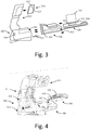
- FIG. 3 illustrates a side view
- FIG. 4 illustrates a perspective view of a docking frame 300 and tool holder 302 for mounting the charging module 100.
- a docking frame 300 and/or tool holder 302 is not only secured to a surface, but also holds the tool in position relative to the charging module.
- the docking frame 300 includes a receiving interface 303 configured to removably receive the mounting interface 104 of the charging module 100 ( Fig. 2 ).
- the geometry of the mounting interface 104 and the receiving interface 303 are configured to engage with each other, such as via a nub-and-slot interface, or the like.
- the receiving interface 303 has a geometry that is at least partially complementary to geometry of the mounting interface 104 of the charging module 100.
- one of the receiving interface 303 and the mounting interface 104 can include a protruding rib, and the other can include a rib-shaped recession configured to slidingly receive the rib.
- Other types of interfaces are also contemplated, including roller interfaces, and snap interfaces, as described in further detail below.
- the receiving interface 303 can also include a stop member (not shown) configured to limit an extent to which the charging module 100 can be inserted into the docking frame 300.
- the stop member can include, for example, a ridge protrusion, a back-wall, a cross-member, and a ridge located on a rail of the receiving interface 303
- the docking frame 300 includes a second mounting interface 304 that enables the docking frame to be mounted in the tool holder 302.
- the tool holder 302 includes a second receiving interface 306, a further stop member 310, and a tool holder portion 311, and defines an attachment surface 314 that forms a base of the tool holder 302.
- the attachment surface 314 is configured to affix the tool holder 302 to a surface such as a desk, table, or the like.
- the tool holder 302 further defines side attachment holes 316 on a surface perpendicular to the base 314 that are configured to mount the tool holder on a wall or side of a structure.
- the second receiving interface 306 is configured to receive the mounting interface 304 of the docking frame 300 in a manner similar to the engagement between the mounting interface 104 and receiving interface 303 of the charging module 100 and docking frame 300.
- the second mounting interface 304 is a protruding rail that is configured to be slidingly received in, for example, a slot (not shown) of the second receiving interface 306, but other types of mounting interfaces are also contemplated.
- the second receiving interface 306 is oriented at an angle 312 relative to the base 314 of the tool holder 302 such that the side of the second receiving interface 306 facing away from the further stop member 310 is elevated compared to the opposite side of the second receiving interface 306. Due to the angle 312, the docking frame 300, when mounted via the second receiving interface 306, is urged by gravity to slide down along the second receiving interface 306 toward the tool holding portion 311.
- the further stop member 310 is configured to engage with the additional stop member 308 of the docking frame 300 to delimit a range of motion of the docking frame 300 along the slot 313 into the tool holder 302.
- the charging surface 102 of the charging module 100 is also oriented at the angle 312 when the charging module 100 is mounted in the docking frame 300.
- the charging module 100 is oriented such that the charging surface 102 slopes downward toward the tool holding portion 311.
- the charging module 100 may be directly mounted in the second receiving interface 306.
- a charging module may be of a size that is too large for the docking frame 300, and thus the mounting interface of the large size charging module is configured to directly engage the second mounting interface 306.
- the tool holder portion 311 extends upwards from a region of the second receiving interface 306 proximate to the further stop member 310, and is configured to at least partially support the body of a tool disposed on the charging surface 102. Because the charging surface 102 is oriented at the angle 312, the tool is urged by gravity into the tool holder portion 311. The magnitude of the angle 312 is selected to enable a user to insert and remove the tool from the tool holder portion 302 via a swiping motion that results in a bottom surface of the tool sliding against the charging surface 102 so as to clear any debris disposed thereon.
- the tool holder 311 thus acts as a transverse support for a device resting on the sloped charging surface 102.
- the tool holding portion 311 is configured to counteract motion such as road vibrations so that the tool is kept optimally positioned relative to the charging surface 102 for charging the battery.
- the tool holding portion 311 is configured to apply a load to the tool that acts to keep the battery within the tool optimally positioned relative to the charging surface 102.
- the load applied by the tool holding portion 311 is counteracted by the charging surface 102 of the charging module.
- the tool holding portion 311 is configured such that the load is applied in a direction along a centerline of an induction coil of the battery within the tool such that the centerline of the induction coil of the battery is held within a tolerance zone 313 of a centerline of the induction coil 103 of the charging module 100.
- the tolerance zone 313 of the charging module 100 is determined based at least in part upon design characteristics of the particular charging module 100 being used, and defines a region within which the battery is optimally charged.
- the tool holding portion 311 is configured such that an orientation of the load is determined by an orientation of the induction coil of at least one of the battery and the charging module 100, and is not determined by a shape or orientation of the tool.
- the tool holding portion 311 further includes a soft insert structure 314 configured to receive the tool.
- the soft insert structure 314 is advantageously a removable structure as illustrated in FIGs. 3 and 4 , but in some embodiments, the soft insert structure 314 is integral with the tool holding portion 311. In such embodiments, different soft insert structures 314 can be used to mount different tools in the tool holder 302.
- the soft insert structure 314 is further configured to have an interference fit with the tool, whereby the interference fit acts as at least a part of a source of the load acting on the tool. While a hard insert structure may also be acceptable to receive the tool in the tool holding portion 311, the soft insert structure 314 includes a soft material that provides damping in restraining the tool. In one embodiment, the soft insert structure 314 includes a hard surface or shell 315 configured to mate with the tool holding portion 311 and a soft receiving area 317 configured to receive the tool.
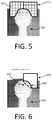
- the soft insert structure 314 is formed from a foam material.
- foam material is molded into a soft insert structure 314 for a particular tool 500 desirably mounted in the tool holder 302.
- a generic foam structure is cut in order to reshape the foam structure into a soft insert structure 314 for a particular tool.
- the foam structure includes cut guides 502 for a plurality of sections of the foam structure configured to guide cutting of the foam structure for a plurality of different soft insert structures 314.
- the cut guides 502 can be used by a user to cut a generic foam structure to fit a tool holding portion 311 and/or a particular tool.
- the soft insert structure 314 includes a sealed air bladder 600.
- the bladder 600 is configured to adjust an amount of air disposed therein.
- the bladder 600 has an expanded shape 602 such that when the bladder 600 is expanded when mounted on the tool 500, the surface 604 expands to have a close fit with the tool 500.
- the amount of air in the bladder 600 can also be adjusted in order to adjust an amount of load applied on the tool 500.
- the bladder 600 includes an expandable foaming agent that is configured to expand and form the bladder 600 into the soft insert structure 314.
- a bladder 600 that includes a foaming agent is positioned between the tool and the tool holding portion 311. The foaming agent is then activated, such as by operating an activation tab (not shown) that, when pulled, causes the foaming agent to form foam, causing the bladder to expand around the tool, and forming the soft insert structure 314.
- the soft insert structure 314 can have, for example, an air tight fit, a pressurized fit, or an open fit around the tool 500, whereby the type of fit affects an amount of resistance for insertion and removal of the tool from the tool holder 302.
- the soft insert structure 314 includes an air bladder 600 as depicted in FIG. 6
- the fit can be adjusted by adjusting an amount of air within the air bladder 600.
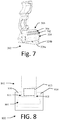
- the tool holder 302 and a tool mounted thereon may be subjected to various vibration forces, such as road vibrations, or vibrations from other sources such as heavy machinery, and additional vibration damping may be beneficial.
- the tool holder 302 has a double-walled structure with an inner surface 328a and an outer surface 328b.
- a gap 330 between the inner surface 328a and outer surface 328b provides vibrational damping for the tool holder 302.
- the gap 330 is filled with air, although filling the gap 330 with other materials such as a vibration damping material is also contemplated.
- the tool holder 302 has a blown molded structure configured to damp vibrations.
- the tool holder 302 can include one or more parts formed by a blow molding process and having a structure that provides structural dampening.
- the tool holder 302 holds the tool in place relative to the charging module 100 to counteract external motions and vibrations.
- installation and removal of the tool to and from the tool holder 302 is optimized so as not to interfere with ready use of the tool.
- a user be able to easily insert or remove the tool with one hand.
- Such one-handed manipulation is enabled by, for example, the angle 312 ( FIG. 3 ) which enable the swiping motion described above, and also by adjusting an amount of resistance of the tool holder 302 exerts when installing or removing the tool.
- the amount of resistance can be adjusted by adjusting the fit of the soft insert structure 314.
- the amount of resistance can also be adjusted by adjusting a thickness of the material used to form the tool holder 302 and/or the docking frame 300.
- the amount of resistance can be adjusted by forming the tool holder 302 with a shape configured to form a seal or pressure fit with the tool.
- FIG. 8 illustrates a front view of a tool holder 800, a tool 802 mounted in the tool holder 800, and a charging module 804 mounted in the tool holder 800.
- the tool holder 800 further includes stops 810 configured to engage a geometry 811 of the tool 802 to hold the tool 802 in place and to counteract a force of the charging module 804 against the tool 802. The tool 802 is thus held in a position for optimal charging of a battery 813 disposed therein.
- the stops 810 also are configured to act as an indicator to a user that the battery is properly aligned with the charging module 804, i.e., when the stops 810 are engaged by the tool 802, the battery within the tool 802 is properly aligned.
- stops similar to the stops 810 can be disposed on the charging module and configured to engage with the tool 802, disposed on a docking frame mounted in the tool holder 800, or can be disposed on the tool 802 and configured to engage with the charging module 804, a docking frame, or the tool holder 800.
- the tool holder 302 and/or the docking frame 300 is configured to accommodate batteries, tools, and charging modules 100 of different sizes.
- the second receiving interface 306 includes a first drawer slot 702 configured to receive a first charging module and/or docking frame, and a second drawer slot 704 configured to receive a second charging module and/or docking frame of a size larger than a size of the first charging module and/or docking frame.
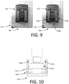
- FIG. 9 illustrates a top view of an over-center clamp mechanism 900 configured to guide the region of the battery 902 into alignment with the charging module 100.
- the over-center clamp mechanism 900 can be, for example, included with the docking frame 300 and/or the tool holder 302 shown in FIGs. 3 and 4 .
- the over-center clamp mechanism 900 is advantageously configured to close from an open position 904 to a closed position 906 as the region of the tool is inserted into the tool holder 302 such that the over-center clamp mechanism 900 is engaged with at least three sides of the tool 908a-c.
- the over-center clamp mechanism 900 includes a spring (not shown) that is positioned at any acceptable location on the mechanism 900 and configured to apply a load when the over-center clamp mechanism 900 is in the closed position that acts to keep the region of the tool in alignment with the charging module 100.
- FIG. 10 illustrates a front view of another embodiment of a tool holder 1000 configured to accommodate different sizes of batteries and/or charging modules.
- the tool holder 1000 includes a plurality of spring loaded pin pairs 1002.
- the charging module 1004 rests on top of one of the spring loaded pin pairs 1002 that is spaced away from stops 1006 by a distance configured to receive the charging module 1004.
- FIG. 11 illustrates a front view of the tool holder 1000 whereby the topmost spring loaded pin pairs 1002 has been retracted such that the tool holder can receive a larger charging module 1104.
- the charging module 1104 thus rests on a spring loaded pin pairs 1002 below the spring loaded pin pairs 1002 retracted in order to accommodate the charging module 1104.
- the charging module 1004 is mounted within the tool holder 1000 and rests on the lower spring loaded pin pairs 1002, and a larger battery region of a tool extends below the stops 1006.
- FIG. 12 illustrates a front view of a tool holder 1200, a tool 1202 mounted in the tool holder 1200, and a charging module 1204 mounted in the tool holder 1200 and urged against the tool 1202.
- the tool holder 1200 includes a pushing mechanism 1206 configured to push on a bottom surface 1208 of the charging module 1204 such that the charging module 1204 is urged against the tool 1202.
- the pushing mechanism 1206 includes a spring and/or spring plate.
- the tool holder 1200 further includes stops 1210 configured to hold the tool 1202 in place and to counteract a force of the charging module 1204 against the tool 1202. The tool 1202 is thus held in a position for optimal charging of a battery 1213 disposed therein.
- FIG. 13 illustrates a front view of another embodiment of a tool holder 1300 configured to urge the charging module 1304 against the tool 1302.
- the pushing mechanism 1306 includes a wedge 1308 and a pushing wedge block 1310.
- the pushing wedge block 1310 can be mounted on a threaded rod, for example, and can be pushed against the wedge 1308, for example, by adjusting the threaded rod, causing the wedge 1308 to push the charging module 1304 against the stops 1308 and the tool 1302.
- Pushing devices such as the pushing mechanisms 1206, 1306 described above can also be used to adjust for different size batteries and/or charging modules.
- FIG. 14 illustrates another embodiment of a tool holder 1400 according to the disclosure.
- the tool holder 1400 includes a back member 1402 configured to apply a load to the tool 1400 mounted within the tool holder 1400 that acts to keep the tool 1400 optimally positioned related to the charging module 1410.
- the tool holder 1400 further includes a front stop 1406 configured to engage with at least one of the tool 1400 and the charging module 1410 and limit an extent of motion of at least one of the tool 1400 and the charging module 1410, and a strap 1408 configured to hold the tool 1400 in place.
- the strap 1408 is additionally configured to be tightened so as to apply a load that urges the tool 1400 against the charging module 1410.
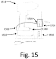
- FIG. 15 illustrates a further embodiment according to the disclosure.
- a clamp mechanism 1500 is configured to urge the tool 1512 against the charging module 1502, and includes a clamping end 1504 configured to engage with a restraining member 1506 such as a rod, pole, bar, pipe, etc., and a gripping end 1508 configured to engage with the tool 1512.
- the gripping end 1508 includes gripping tines, but other types of gripping ends, such as a loop connection, clip connection, and pin connection are also contemplated.
- the charging module 1502 additionally includes a lip 1510 configured to hold the tool 1512 captive on the charging module 1502 in conjunction with the clamp mechanism 1500.
- the clamp mechanism is advantageously configured to have an adjustable length such that a variety of thickness of the tool 1512 and charging module 1502 can be accommodated.
- the docking frame 300 and/or the tool holder 302 includes a cord guide configured to guide a power cord out from the charging module, through the docking frame 300 and/or tool holder 302, such that the power cord to be connected to a power source is unobstructed by the docking frame 300 and/or tool holder 302.
- tool holders and docking frames may be configured to be used with different tools, and so to may different charging modules be configured to be used with different batteries and with different docking stations.
- a plurality of different tool holders are configured to be used with different docking frames and charging modules of different sizes and powers via common interfaces.
- a first docking frame is mounted within a tool holder, and houses a first charging module.
- the first tool holder and the first charging module are configured to work with a first tool.
- the first docking frame is removed from the tool holder, and a second docking frame housing a second charging module is inserted therein, wherein the second charging module is configured to charge the second tool, and wherein the second docking frame has a mounting interface configured to engage with the receiving interface of the tool holder.
- tool holders, docking frames, and charging modules may be mixed and matched as desired due to common mounting and receiving interfaces.
- a tool holder in an exemplary embodiment according to this disclosure, includes a receiving interface, and tool holding portion.
- the interface is configured to receive a wireless charging module for charging a battery positioned within a tool
- the holding portion is configured to receive the tool and apply a load to the tool that acts to hold the tool in alignment with the charging module for optimal charging of the battery.
- the tool holder has an attachment surface that can be affixed to a rigid surface.
- the receiving interface includes a removable docking frame that has a second receiving interface configured to engage a mounting interface of the charging module.
- the tool holding portion is adjustable to adjust an amount of resistance for installing or removing the tool therein.
- the tool holding portion includes a soft insert structure configured to receive the tool with an interference fit, wherein at least part of the load is applied by the soft insert structure.
- the soft insert structure is removably inserted in the tool holding portion, and is configured to receive a particular tool.
- the tool holder includes a positive stop configured to engage with and hold the tool such that the battery is aligned with the charging module.
- the positive stop is further configured to act as an alignment indicator that indicates that the battery is optimally aligned with the charging module.
Landscapes
- Engineering & Computer Science (AREA)
- Power Engineering (AREA)
- Computer Networks & Wireless Communication (AREA)
- Charge And Discharge Circuits For Batteries Or The Like (AREA)
Description
- This invention claims priority to
U.S. Provisional Application No. 62/059,333 filed on October 3, 2014 - This invention relates generally to wireless chargers, and, more particularly, to wireless chargers for power tools.
- A common problem associated with the use of electronic devices and tools is the necessity of powering such electronic devices. Power cords connected to an external power source provide sufficient power, but are an obtrusive and problematic interference, especially with regard to power tools which are desirably easily manipulated in and around workspaces that are often crowded and obstructed, and power tools which are desirably transported between different job sites.
- Rechargeable cordless tools are a common alternative. Such systems typically include a removable rechargeable battery and a charging station. When depleted, a rechargeable battery can be removed from the tool and inserted into the charging station for charging.
U.S. Patent No. 5,144, 217 describes a cordless tool battery housing and charging system that accommodates a variety of sizes and power charges of different batteries via a controlled wired charging process. Such technologies typically require not only removal of the battery from the tool in order to initiate charging, but also require a wired contact connection between the battery and charging station, which may be susceptible to damage due to, for example, moisture, dirt, or physical damage that prevents the battery from optimally coupling with the charging station. - Technology has been developed in an effort to alleviate these concerns via inductive or wireless charging.
U.S. Patent No. 8,482,160 describes a system whereby a plurality of wireless charging modules are placed underneath a workspace in order to inductively charge a secondary tool placed on the workspace in a region of one of the modules. However, such a system is expensive and complex to install, only enables wireless charging at the fixed regions of the modules, does not ensure that a tool is optimally located within a charging region for optimal charging, and is inapplicable to mobile applications. Further, such a system does not provide protection against a tool being unintentionally jostled and relocated during charging. For instance, a user might place a tool near a charging module with the expectation that the tool will charge. The user might then continue work with another device or tool, and in so doing, unintentionally move the tool away from the module, such that when the user again wishes to use the tool, it has not been charged as desired. Other conventional wireless chargers resemble pads, and are similarly unsecured. - Other types of wireless charging devices have also been developed for charging tools and other devices, and typically resemble a pad on which a device is rested to initiate charging. However, such chargers present undesirable use cases when used as a tool resting surface since they are not secured to a supporting surface, nor do they secure the tool itself from unintended motion or vibration.
- In one such undesirable use case, a user is operating a power drill powered by a rechargeable battery. When the battery becomes depleted, the drill becomes inoperable. In order to resume work, the user can, for example, replace the depleted battery with a charged replacement battery, or place the battery and/or tool onto a charging station and wait for the battery to recharge. Replacing the battery requires the user to obtain, store, and maintain charging for multiple batteries, which increases the expense and complexity of operating the drill, and waiting for the battery to recharge can necessitate delays in workflow before the user can resume drilling.
- Additionally, conventional wireless charging stations do not guide an optimal location of the battery/tool for optimized charging, and do not secure the battery/tool in place. As a result, the battery/tool that is not optimally placed on a wireless charging station may charge slower or may fail to completely charge. Even if optimally placed, the battery/tool may become dislodged or moved due to inadvertent contact from the user, another tool or object, or other external forces such as vibrations from machinery. In another example, a charging station is positioned in a vehicle, and a battery/tool is placed thereon for charging. During transport, motion from the vehicle can jostle the battery/tool out of position and hinder or prevent charging. These types of impacts, jostling, and vibrations can also result in damage to the battery/tool when the battery/tool is unsecured.
- In the published patent prior art,
DE 10 2013 226 220 A1 discloses a wireless charging system in which there is provided a holding portion holding a power tool, whereby the tool is simply compressed between the holding portion and the charging surface by its own weight. - Therefore, the object of the present invention is to provide a wireless charging system allowing charging a battery of a tool without interrupting its use or obstructing a workspace with cords with a charging station in such a way that optimally positions the tool for charging and protects against unintentional interruption of charging of the tool.
- This object is solved by
claim 1 and further advantageous embodiments and improvements of the invention are listed in the dependent claims. Hereinafter, before coming to a detailed discussion of the embodiments of the invention with respect to the attached drawings, some aspects of the invention are described which contribute to the understanding of the invention. However, it should be noted that the invention is defined by the attached claims and embodiments which are not covered by the claims are also to be understood as examples and aspects which contribute to the understanding of the invention.
The following is a brief summary of aspects of the subject matter described in greater detail herein. This summary is not intended to be limiting as to the scope of this disclosure or to the claims. - In order to facilitate the charging of a power tool, a wireless charging system includes a tool holder, a docking frame mounted in the tool holder, and a charging module mounted in the docking frame so that a charging surface of the charging module is at an angle. The charging module includes an inductive charging device, and the tool holder includes a holding portion that extends from a downward region of the charging module to transversely support a power tool resting on the charging surface.
- A soft insert structure is received between the power tool and the holding portion of the tool holder, and forms an interference fit between the power tool and the tool holder. Different soft insert structures enable the tool holder to receive different power tools with an interference fit. The soft insert structure applies a load to the power tool in a direction of the charging surface that urges the power tool toward a location for optimal charging relative to the inductive charging device.
- A pushing device can be mounted between the charging module and the docking frame, or between the docking frame and the tool holder, and is configured to load the charging module in order to apply a force to the power tool in opposition to the load applied by the soft insert structure.
- A strap or clamping device can be used to secure the power tool within the tool holder.
-
-
FIG. 1 is a side view of a wireless charging module according to this disclosure. -
FIG. 2 is a perspective view of the wireless charging module ofFIG. 1 . -
FIG. 3 is a side view of a tool holder for mounting a docking frame and the charging module ofFIG. 1 according to this disclosure. -
FIG. 4 is an exploded perspective view of a tool holder, docking frame, and charging module ofFIG. 3 . -
FIG. 5 is a rear view of an exemplary embodiment of a soft insert structure for a tool according to this disclosure. -
FIG. 6 is a rear view of another exemplary embodiment of a soft insert structure for a tool according to this disclosure. -
FIG. 7 is a perspective cross section view of a tool holder according to this disclosure. -
FIG. 8 is a front view of an exemplary tool holder according to this disclosure. -
FIG. 9 is a top view of an exemplary embodiment of a clamping device for a tool according to this disclosure. -
FIG. 10 is a front view of another exemplary embodiment of a tool holder according to this disclosure -
FIG. 11 is a front view of the tool holder ofFIG. 10 with a different sized component inserted therein. -
FIG. 12 is a front view of a tool holder having a pushing mechanism according to this disclosure. -
FIG. 13 is a front view of another embodiment of a tool holder having a pushing mechanism according to this disclosure. -
FIG. 14 is a side view of a tool holder having a strap mechanism according to this disclosure. -
FIG. 15 is a side view of a tool holder having a clamp mechanism according to this disclosure. - For the purposes of promoting an understanding of the principles of the embodiments described herein, reference is now made to the drawings and descriptions in the following written specification. No limitation to the scope of the subject matter is intended by the references. This disclosure also includes any alterations and modifications to the illustrated embodiments and includes further applications of the principles of the described embodiments as would normally occur to one of ordinary skill in the art to which this document pertains.
-
FIG. 1 depicts a side view andFIG. 2 depicts a perspective view of awireless charging module 100 according to this disclosure. Thewireless charging module 100 defines a chargingsurface 102, and includes aninduction charging coil 103, a mountinginterface 104, and a plurality offeet 108. - The charging
surface 102 is formed by a top surface of the charging module. Theinduction charging coil 103 is disposed within thecharging module 100, and is configured to inductively charge a rechargeable battery placed on or near a chargingsurface 102. Acceptable wireless inductive battery charging systems are described inU.S. Patent No. 5,959,433 ,WO2014/096052 ,WO2014/096037 , andWO2014/096048 . Other types of conventional inductive charging systems are also contemplated. For example, thewireless charging module 100 supports Qi inductive charging or the like. - The mounting
interface 104 is disposed on the lateral sides of thecharging module 100, and is configured to removably mount thecharging module 100 within another structure, such as a docking frame or tool holder as discussed below, to enable rigid support of thecharging module 100 on a surface, wall, tool box, vehicle, cart, work surface, or the like. As illustrated inFIG. 2 , in this embodiment the mountinginterface 104 includes arail 106 configured to removably mate with a receiving interface of the other structure. In other embodiments, the mountinginterface 104 can include one or more of, for example, a rail, a snap structure, a roller, or other removable mounting structures. - The plurality of
feet 108 are disposed on a bottom of thecharging module 100 opposite the chargingsurface 102, and are configured to provide at least partial damping and/or restraint against motion. For example, the plurality offeet 108 can provide at least partial damping relative to the other structure housing thecharging module 100, or can provide at least partial damping when thecharging module 100 is not mounted in another structure and is resting directly on an unsecured surface. Thefeet 108 can include rubber footing, grips, or other structure configured to arrest motion or provide damping. In another embodiment, the mountinginterface 104 includes a damping material configured to provide at least partial damping between the chargingmodule 100 and the other structure. - The
charging module 100 can be used to charge a removable battery that is not connected to a tool but is instead placed directly on the chargingsurface 102, or can be used to charge a battery configured to remain within a tool during charging. In some cases, a battery within a tool may be spaced apart from a bottom surface of the tool. Thus, the optimal position for a battery for wireless charging via theinduction charging coil 103 may be on or near the chargingsurface 102, or at a distance spaced apart from the chargingsurface 102. In an embodiment, thecharging module 100 is configured to adjust the optimal charging location based on the tool or device placed on the chargingsurface 102. - The
charging module 100 is usable to charge a variety of sizes and powers of batteries. For example, the battery can include a Lithium ion battery, a Lithium air battery, a Lithium metal battery, a Lithium sulfur battery, or a metal-air battery. Thecharging module 100 can also be used to charge multiple batteries or multiple tools at once - In an embodiment, the
charging module 100, in addition to being configured to transfer energy to charge the tool and/or battery, is further configured to transfer energy to charge at least one non-power tool device such as, for example, a battery tester, a vehicle diagnostic system, a wireless device, a wearable device, a mobile device, or a device for a vehicle. - Because the
induction charging coil 103 enables wireless charging, thecharging module 100 does not need a physical contact point for electrically connecting the battery/tool to the charging module. In conventional chargers, contact points can become obstructed by debris, or can be damaged such as by wear or impact, which can negatively impact the performance of the charger. Many types of contact points also require that the battery or tool is removably coupled to the charger, which necessitates a decoupling action before the battery/tool can be removed. By eliminating contact points, thecharging module 100 not only removes the risk of debris or impact affecting the performance of charging a battery, but also enables maintaining a tool in an always-ready condition where the tool is easily removable from thecharging module 100 without requiring any detachment or decoupling. - The charging
surface 102 of thecharging module 100 can be used as a resting surface on which the tool may be placed when not in active use. In an exemplary use case, a user performing a repetitive drilling operation can iterate between operating a power drill with a rechargeable battery, and inserting a member into a hole resulting from the drilling operation. When using a conventional rechargeable drill, the battery is continually drained during operation, and continues to drain or at best holds steady when not in use. According to this disclosure, when inserting the member into the hole, the user can place the drill on the chargingsurface 102 of thecharging module 100, and then the user can retrieve the drill for the subsequent drilling operation. In this way, the battery of the drill is at least partially recharged each time it is set aside while the user inserts a member. Because placing and removing the drill on the chargingsurface 102 does not require a coupling or uncoupling action, the drill can be placed and recovered without interruption to the user's workflow. Additionally, because the drill is charged whenever it is resting on the chargingsurface 102, the time over which the drill can be operated without stopping to recharge or replace the battery is extended relative to conventional charging systems. - In one embodiment, the
charging module 100 further includes an electric plug (not shown) configured to connect thecharging module 100 to an electrical power source, such as a wall socket, car power outlet, power converter, etc. In an embodiment, the charging module also includes a charging control unit (not shown) that is configured to operate theinduction charging coil 103 to control a charging operation. Such a charging control unit can include a wireless communication device for communicating with, for example, a battery, a tool, a mobile device, or the like such as an RF antenna, near field communication (NFC), WiFi, Bluetooth, or the like. For example, the charging control unit can be configured to communicate with the battery and/or the tool to charge the battery based at least in part upon a charge level and/or state of the battery. - As discussed above, mounting the
charging module 100 on another structure can be beneficial for securing the battery/tool during charging or between periods of use.FIG. 3 illustrates a side view, andFIG. 4 illustrates a perspective view of adocking frame 300 andtool holder 302 for mounting thecharging module 100. Advantageously, adocking frame 300 and/ortool holder 302 is not only secured to a surface, but also holds the tool in position relative to the charging module. - The
docking frame 300 includes a receivinginterface 303 configured to removably receive the mountinginterface 104 of the charging module 100 (Fig. 2 ). In this embodiment, the geometry of the mountinginterface 104 and the receivinginterface 303 are configured to engage with each other, such as via a nub-and-slot interface, or the like. - In another embodiment, the receiving
interface 303 has a geometry that is at least partially complementary to geometry of the mountinginterface 104 of thecharging module 100. For example, one of the receivinginterface 303 and the mountinginterface 104 can include a protruding rib, and the other can include a rib-shaped recession configured to slidingly receive the rib. Other types of interfaces are also contemplated, including roller interfaces, and snap interfaces, as described in further detail below. - The receiving
interface 303 can also include a stop member (not shown) configured to limit an extent to which thecharging module 100 can be inserted into thedocking frame 300. The stop member can include, for example, a ridge protrusion, a back-wall, a cross-member, and a ridge located on a rail of the receivinginterface 303 - In addition to a receiving interface configured to receive a charging module (not shown), the
docking frame 300 includes asecond mounting interface 304 that enables the docking frame to be mounted in thetool holder 302. - The
tool holder 302 includes asecond receiving interface 306, afurther stop member 310, and atool holder portion 311, and defines anattachment surface 314 that forms a base of thetool holder 302. - The
attachment surface 314 is configured to affix thetool holder 302 to a surface such as a desk, table, or the like. In this embodiment, thetool holder 302 further defines side attachment holes 316 on a surface perpendicular to the base 314 that are configured to mount the tool holder on a wall or side of a structure. - The
second receiving interface 306 is configured to receive the mountinginterface 304 of thedocking frame 300 in a manner similar to the engagement between the mountinginterface 104 and receivinginterface 303 of thecharging module 100 anddocking frame 300. For example, in this embodiment, thesecond mounting interface 304 is a protruding rail that is configured to be slidingly received in, for example, a slot (not shown) of thesecond receiving interface 306, but other types of mounting interfaces are also contemplated. - The
second receiving interface 306 is oriented at anangle 312 relative to thebase 314 of thetool holder 302 such that the side of thesecond receiving interface 306 facing away from thefurther stop member 310 is elevated compared to the opposite side of thesecond receiving interface 306. Due to theangle 312, thedocking frame 300, when mounted via thesecond receiving interface 306, is urged by gravity to slide down along thesecond receiving interface 306 toward thetool holding portion 311. Thefurther stop member 310 is configured to engage with theadditional stop member 308 of thedocking frame 300 to delimit a range of motion of thedocking frame 300 along theslot 313 into thetool holder 302. - Since the
docking frame 300 is oriented at theangle 312, the chargingsurface 102 of thecharging module 100 is also oriented at theangle 312 when thecharging module 100 is mounted in thedocking frame 300. In other words, thecharging module 100 is oriented such that the chargingsurface 102 slopes downward toward thetool holding portion 311. - In another embodiment, (not shown) the
charging module 100 may be directly mounted in thesecond receiving interface 306. For example, a charging module may be of a size that is too large for thedocking frame 300, and thus the mounting interface of the large size charging module is configured to directly engage thesecond mounting interface 306. - The
tool holder portion 311 extends upwards from a region of thesecond receiving interface 306 proximate to thefurther stop member 310, and is configured to at least partially support the body of a tool disposed on the chargingsurface 102. Because the chargingsurface 102 is oriented at theangle 312, the tool is urged by gravity into thetool holder portion 311. The magnitude of theangle 312 is selected to enable a user to insert and remove the tool from thetool holder portion 302 via a swiping motion that results in a bottom surface of the tool sliding against the chargingsurface 102 so as to clear any debris disposed thereon. Thetool holder 311 thus acts as a transverse support for a device resting on the slopedcharging surface 102. - The
tool holding portion 311 is configured to counteract motion such as road vibrations so that the tool is kept optimally positioned relative to the chargingsurface 102 for charging the battery. Advantageously, thetool holding portion 311 is configured to apply a load to the tool that acts to keep the battery within the tool optimally positioned relative to the chargingsurface 102. The load applied by thetool holding portion 311 is counteracted by the chargingsurface 102 of the charging module. When a tool is placed on thecharging module 100 mounted in thedocking frame 300 andtool holder 302 as illustrated inFIGs 3 and 4 , the load applied by thetool holding portion 311 and the counter-action of the chargingsurface 102 act compressively on the tool in order to securely hold the tool in the tool holder at an optimal location for charging the tool via thecharging module 100. - Specifically, the
tool holding portion 311 is configured such that the load is applied in a direction along a centerline of an induction coil of the battery within the tool such that the centerline of the induction coil of the battery is held within atolerance zone 313 of a centerline of theinduction coil 103 of thecharging module 100. Thetolerance zone 313 of thecharging module 100 is determined based at least in part upon design characteristics of theparticular charging module 100 being used, and defines a region within which the battery is optimally charged. In one aspect, thetool holding portion 311 is configured such that an orientation of the load is determined by an orientation of the induction coil of at least one of the battery and thecharging module 100, and is not determined by a shape or orientation of the tool. - The
tool holding portion 311 further includes asoft insert structure 314 configured to receive the tool. Thesoft insert structure 314 is advantageously a removable structure as illustrated inFIGs. 3 and 4 , but in some embodiments, thesoft insert structure 314 is integral with thetool holding portion 311. In such embodiments, differentsoft insert structures 314 can be used to mount different tools in thetool holder 302. - The
soft insert structure 314 is further configured to have an interference fit with the tool, whereby the interference fit acts as at least a part of a source of the load acting on the tool. While a hard insert structure may also be acceptable to receive the tool in thetool holding portion 311, thesoft insert structure 314 includes a soft material that provides damping in restraining the tool. In one embodiment, thesoft insert structure 314 includes a hard surface or shell 315 configured to mate with thetool holding portion 311 and asoft receiving area 317 configured to receive the tool. - In one embodiment illustrated in
FIG. 5 , thesoft insert structure 314 is formed from a foam material. In an embodiment, foam material is molded into asoft insert structure 314 for aparticular tool 500 desirably mounted in thetool holder 302. In another embodiment, a generic foam structure is cut in order to reshape the foam structure into asoft insert structure 314 for a particular tool. In one embodiment of a foam structure, the foam structure includes cut guides 502 for a plurality of sections of the foam structure configured to guide cutting of the foam structure for a plurality of differentsoft insert structures 314. For example, the cut guides 502 can be used by a user to cut a generic foam structure to fit atool holding portion 311 and/or a particular tool. - In another embodiment illustrated in
FIG. 6 , thesoft insert structure 314 includes a sealedair bladder 600. Thebladder 600 is configured to adjust an amount of air disposed therein. For example, in this embodiment, thebladder 600 has an expandedshape 602 such that when thebladder 600 is expanded when mounted on thetool 500, thesurface 604 expands to have a close fit with thetool 500. The amount of air in thebladder 600 can also be adjusted in order to adjust an amount of load applied on thetool 500. - In one embodiment, rather than being expanded by air, the
bladder 600 includes an expandable foaming agent that is configured to expand and form thebladder 600 into thesoft insert structure 314. In an example, abladder 600 that includes a foaming agent is positioned between the tool and thetool holding portion 311. The foaming agent is then activated, such as by operating an activation tab (not shown) that, when pulled, causes the foaming agent to form foam, causing the bladder to expand around the tool, and forming thesoft insert structure 314. - The
soft insert structure 314 can have, for example, an air tight fit, a pressurized fit, or an open fit around thetool 500, whereby the type of fit affects an amount of resistance for insertion and removal of the tool from thetool holder 302. In one embodiment where thesoft insert structure 314 includes anair bladder 600 as depicted inFIG. 6 , the fit can be adjusted by adjusting an amount of air within theair bladder 600. - During operation, transport, and storage, the
tool holder 302 and a tool mounted thereon may be subjected to various vibration forces, such as road vibrations, or vibrations from other sources such as heavy machinery, and additional vibration damping may be beneficial. In the embodiment illustrated inFIG. 7 , thetool holder 302 has a double-walled structure with aninner surface 328a and anouter surface 328b. Agap 330 between theinner surface 328a andouter surface 328b provides vibrational damping for thetool holder 302. In some embodiments, thegap 330 is filled with air, although filling thegap 330 with other materials such as a vibration damping material is also contemplated. In one aspect, thetool holder 302 has a blown molded structure configured to damp vibrations. In an example, thetool holder 302 can include one or more parts formed by a blow molding process and having a structure that provides structural dampening. - As described above, the
tool holder 302 holds the tool in place relative to thecharging module 100 to counteract external motions and vibrations. However, it is also desirable that installation and removal of the tool to and from thetool holder 302 is optimized so as not to interfere with ready use of the tool. In particular, it is desirable that a user be able to easily insert or remove the tool with one hand. Such one-handed manipulation is enabled by, for example, the angle 312 (FIG. 3 ) which enable the swiping motion described above, and also by adjusting an amount of resistance of thetool holder 302 exerts when installing or removing the tool. As described above, the amount of resistance can be adjusted by adjusting the fit of thesoft insert structure 314. The amount of resistance can also be adjusted by adjusting a thickness of the material used to form thetool holder 302 and/or thedocking frame 300. In another example, the amount of resistance can be adjusted by forming thetool holder 302 with a shape configured to form a seal or pressure fit with the tool. - Because the efficiency of the charging of the battery is based at least in part upon the location of the battery with respect to the
charging module 100, it may be desirable to further restrain the tool and/ordocking frame 300 so as to facilitate an alignment between the battery and thecharging module 100.FIG. 8 illustrates a front view of atool holder 800, atool 802 mounted in thetool holder 800, and acharging module 804 mounted in thetool holder 800. Thetool holder 800 further includesstops 810 configured to engage ageometry 811 of thetool 802 to hold thetool 802 in place and to counteract a force of thecharging module 804 against thetool 802. Thetool 802 is thus held in a position for optimal charging of abattery 813 disposed therein. - The
stops 810 also are configured to act as an indicator to a user that the battery is properly aligned with thecharging module 804, i.e., when thestops 810 are engaged by thetool 802, the battery within thetool 802 is properly aligned. In other embodiments, stops similar to thestops 810 can be disposed on the charging module and configured to engage with thetool 802, disposed on a docking frame mounted in thetool holder 800, or can be disposed on thetool 802 and configured to engage with thecharging module 804, a docking frame, or thetool holder 800. - Advantageously, the
tool holder 302 and/or thedocking frame 300 is configured to accommodate batteries, tools, and chargingmodules 100 of different sizes. In this embodiment, thesecond receiving interface 306 includes afirst drawer slot 702 configured to receive a first charging module and/or docking frame, and asecond drawer slot 704 configured to receive a second charging module and/or docking frame of a size larger than a size of the first charging module and/or docking frame. - It may be desirable to further restrain a region of the tool having the battery.
FIG. 9 illustrates a top view of anover-center clamp mechanism 900 configured to guide the region of thebattery 902 into alignment with thecharging module 100. Theover-center clamp mechanism 900 can be, for example, included with thedocking frame 300 and/or thetool holder 302 shown inFIGs. 3 and 4 . Theover-center clamp mechanism 900 is advantageously configured to close from anopen position 904 to aclosed position 906 as the region of the tool is inserted into thetool holder 302 such that theover-center clamp mechanism 900 is engaged with at least three sides of thetool 908a-c. In one embodiment, theover-center clamp mechanism 900 includes a spring (not shown) that is positioned at any acceptable location on themechanism 900 and configured to apply a load when theover-center clamp mechanism 900 is in the closed position that acts to keep the region of the tool in alignment with thecharging module 100. -
FIG. 10 illustrates a front view of another embodiment of atool holder 1000 configured to accommodate different sizes of batteries and/or charging modules. Thetool holder 1000 includes a plurality of spring loaded pin pairs 1002. Thecharging module 1004 rests on top of one of the spring loaded pin pairs 1002 that is spaced away fromstops 1006 by a distance configured to receive thecharging module 1004.FIG. 11 illustrates a front view of thetool holder 1000 whereby the topmost spring loaded pin pairs 1002 has been retracted such that the tool holder can receive a larger charging module 1104. The charging module 1104 thus rests on a spring loaded pin pairs 1002 below the spring loaded pin pairs 1002 retracted in order to accommodate the charging module 1104. In another embodiment, thecharging module 1004 is mounted within thetool holder 1000 and rests on the lower spring loaded pin pairs 1002, and a larger battery region of a tool extends below thestops 1006. - It may be desirable for a tool holder to be configured to accommodate batteries and/or charging modules of variable size. Additionally, applying a load that urges the
charging module 100 against the tool can be used to adjust the amount of resistance for installing and removing the tool as described above, as well as to keep the tool aligned with thecharging module 100.FIG. 12 illustrates a front view of atool holder 1200, atool 1202 mounted in thetool holder 1200, and acharging module 1204 mounted in thetool holder 1200 and urged against thetool 1202. Thetool holder 1200 includes a pushingmechanism 1206 configured to push on abottom surface 1208 of thecharging module 1204 such that thecharging module 1204 is urged against thetool 1202. In an example, the pushingmechanism 1206 includes a spring and/or spring plate. Thetool holder 1200 further includesstops 1210 configured to hold thetool 1202 in place and to counteract a force of thecharging module 1204 against thetool 1202. Thetool 1202 is thus held in a position for optimal charging of abattery 1213 disposed therein. -
FIG. 13 illustrates a front view of another embodiment of atool holder 1300 configured to urge thecharging module 1304 against thetool 1302. Rather than including a spring and/or a spring plate, the pushingmechanism 1306 includes awedge 1308 and a pushingwedge block 1310. The pushingwedge block 1310 can be mounted on a threaded rod, for example, and can be pushed against thewedge 1308, for example, by adjusting the threaded rod, causing thewedge 1308 to push thecharging module 1304 against thestops 1308 and thetool 1302. - Pushing devices, such as the pushing
mechanisms -
FIG. 14 illustrates another embodiment of atool holder 1400 according to the disclosure. Thetool holder 1400 includes aback member 1402 configured to apply a load to thetool 1400 mounted within thetool holder 1400 that acts to keep thetool 1400 optimally positioned related to thecharging module 1410. Thetool holder 1400 further includes afront stop 1406 configured to engage with at least one of thetool 1400 and thecharging module 1410 and limit an extent of motion of at least one of thetool 1400 and thecharging module 1410, and astrap 1408 configured to hold thetool 1400 in place. Thestrap 1408 is additionally configured to be tightened so as to apply a load that urges thetool 1400 against thecharging module 1410. -
FIG. 15 illustrates a further embodiment according to the disclosure. Aclamp mechanism 1500 is configured to urge thetool 1512 against thecharging module 1502, and includes aclamping end 1504 configured to engage with a restrainingmember 1506 such as a rod, pole, bar, pipe, etc., and agripping end 1508 configured to engage with thetool 1512. In the embodiment, thegripping end 1508 includes gripping tines, but other types of gripping ends, such as a loop connection, clip connection, and pin connection are also contemplated. Thecharging module 1502 additionally includes alip 1510 configured to hold thetool 1512 captive on thecharging module 1502 in conjunction with theclamp mechanism 1500. The clamp mechanism is advantageously configured to have an adjustable length such that a variety of thickness of thetool 1512 andcharging module 1502 can be accommodated. - In a further embodiment the
docking frame 300 and/or thetool holder 302 includes a cord guide configured to guide a power cord out from the charging module, through thedocking frame 300 and/ortool holder 302, such that the power cord to be connected to a power source is unobstructed by thedocking frame 300 and/ortool holder 302. - It is contemplated that different tool holders and docking frames may be configured to be used with different tools, and so to may different charging modules be configured to be used with different batteries and with different docking stations. Thus, in a further embodiment, a plurality of different tool holders are configured to be used with different docking frames and charging modules of different sizes and powers via common interfaces.
- In an example, a first docking frame is mounted within a tool holder, and houses a first charging module. The first tool holder and the first charging module are configured to work with a first tool. When a second tool is desirably charged, the first docking frame is removed from the tool holder, and a second docking frame housing a second charging module is inserted therein, wherein the second charging module is configured to charge the second tool, and wherein the second docking frame has a mounting interface configured to engage with the receiving interface of the tool holder. In other words, tool holders, docking frames, and charging modules may be mixed and matched as desired due to common mounting and receiving interfaces.
- In an exemplary embodiment according to this disclosure, a tool holder includes a receiving interface, and tool holding portion. The interface is configured to receive a wireless charging module for charging a battery positioned within a tool, and the holding portion is configured to receive the tool and apply a load to the tool that acts to hold the tool in alignment with the charging module for optimal charging of the battery. The tool holder has an attachment surface that can be affixed to a rigid surface.
- In one embodiment, the receiving interface includes a removable docking frame that has a second receiving interface configured to engage a mounting interface of the charging module.
- In an embodiment, the tool holding portion is adjustable to adjust an amount of resistance for installing or removing the tool therein.
- In one embodiment, the tool holding portion includes a soft insert structure configured to receive the tool with an interference fit, wherein at least part of the load is applied by the soft insert structure. The soft insert structure is removably inserted in the tool holding portion, and is configured to receive a particular tool.
- In one embodiment, the tool holder includes a positive stop configured to engage with and hold the tool such that the battery is aligned with the charging module. The positive stop is further configured to act as an alignment indicator that indicates that the battery is optimally aligned with the charging module.
- It will be appreciated that variants of the above-described and other features and functions, or alternatives thereof, may be desirably combined into many other different systems, applications or methods. Various presently unforeseen or unanticipated alternatives, modifications, variations or improvements may be subsequently made by those skilled in the art that are also intended to be encompassed by the disclosure.
Claims (18)
- A wireless charging system, comprising:a tool holder (302) that includes:a mounting interface (306); anda holding portion (311) that extends transversely from an end region of the mounting interface; anda charging module (100) that defines a charging surface (102), that is mounted in the mounting interface (306) of the tool holder (302), and that includes an inductive charging device (103) configured to wireless charge a wirelessly rechargeable battery of a tool resting on the charging surface;the holding portion (311) having a shape configured to at last partially engage a geometry of the tool such that the holding portion (311) supports a body of the tool transversely relative to the mounting interface (302), andthe holding portion (311) configured to apply a load to the tool resting on the charging surface (102) such that the tool is at least partially compressed between the holding portion (311) and the charging surface (102) when resting on the charging surface (102) and urged toward location within a wireless charging tolerance zone (313) of a centerline of an induction coil (103) of the charging module (100) within which the battery is optimally charged, wherein the holding portion (311) of the tool holder (302) includes a soft insert (314) structure that defines a cavity sized for an interference fit with at least a portion of the tool, and that is configured to apply at least a portion of the load applied by the holding portion (311); andwherein the soft insert structure (314) includes a bladder (600) that forms the interference fit between the holding portion (311) and the tool as the bladder (600) is expanded therebetween; and whereinthe tool holding portion (311) is configured such that the load is applied in a direction along a centerline of an induction coil of a battery within the tool such that the centerline of the induction coil of the battery is held within the charging tolerance zone (313) of the centerline of the induction coil (103) of the charging module (100).
- The system of claim 1, wherein the expansion of the bladder is adjustable.
- The system of claim 1, wherein the bladder includes a foaming agent disposed therein that forms foam to expand the bladder upon activation.
- The system of claim 1, wherein the soft insert structure includes:a rigid shell (315) that is removably mountable within the holding portion of the tool holder; anda soft receiving area (317) configured to receive at least a portion of the tool.
- The system of claim 1, further comprising a pushing device (1206, 1306) that is disposed in the mounting interface of the tool holder, and that loads the charging module toward the holding portion such that the charging module is configured to apply a load to the tool in opposition to the load applied by the holding portion.
- The system of claim 4, wherein the pushing device includes at least one spring mounted on the mounting interface of the tool holder that is configured to bias the pushing device toward the holding portion.
- The system of claim 4, wherein the pushing device includes an adjustment member (1310, 1308) that is operable to adjust the load applied by the pushing device.
- The system of claim 4, wherein the tool holder further includes at least one stop member (1210) that has a shape configured to engage at least a portion of the geometry of the tool, and that delimits an installation region for the tool such that the tool is located within the tolerance zone of the charging module.
- The system of claim 1, wherein the mounting interface includes a docking frame (300) that is removably mounted within the tool holder, and that includes a receiving interface for mounting the charging module.
- The system of claim 1, wherein the tool holder has a double-walled structure formed by a first wall (328a) and a second wall (328B and a gap (330) defined therebetween.
- The system of claim 10, wherein a damping material is disposed within the gap.
- The system of claim 1, further comprising a strap that is configured to restrain the tool within the tool holder.
- The system of claim 1, comprising:the tool holder that includes:the mounting interface as a first mounting interface; andthe holding portion extending from an end region of the first mounting interface, andthat includes the soft insert structure (317);a docking frame (300) mounted in the first mounting interface, the docking frame including:a second base surface; anda second mounting interface (304); andthe charging module (100) defining the charging surface, that is mounted in the second mounting interface (304), and that includes the inductive charging device that defines the wireless charging tolerance zone;the tool being constituted by a power tool that includes the wirelessly rechargeable battery, and that is disposed on the charging surface (103) of the charging module such that the holding portion at least partially transversely supports the power tool relative to the first mounting interface,the soft insert structure (317) defining the cavity sized for the interference fit with at least the portion of the power tool, and applying the load to the power tool in the the compression direction toward the charging surface such that the power tool is at least partially compressed between the holding portion and the charging surface and urged toward a location such that the battery is within the wireless charging tolerance zone, andthe induction charging device configured to wirelessly charge the battery.
- The system of claim 13, wherein the docking frame includes a pushing device (1206, 1306) that urges the charging module toward the power tool in opposition to the load applied by the holding portion.
- The system of claim 14, wherein at least one of the pushing device and soft insert structure is adjustable in order to adjust a compression of the power tool in the tool holder.
- The system of claim 13, further comprising:a further power tool having a geometry that is different from the geometry of the power tool; anda further soft insert structure that defines a further cavity sized for an interference fit with the further power tool, and that is configured to replace the soft insert structure to enable the tool holder to receive the further power tool with an interference fit.
- The system of claim 13, further comprising at least one of: a strap configured to restrain the power tool within the tool holder; and a clamping device that includes at least one clamping arm, and that is actuatable betweena first position whereat the at least one clamping arm engages the power tool to hold the power tool captive within the tool holder, anda second position whereat the at least one clamping arm is released from the power tool.
- The system of claim 13, wherein at least one of the tool holder and docking frame further includes at least one stop member (310) that delimits an installation location of the power tool so that the battery is within the wireless charging tolerance zone.
Applications Claiming Priority (2)
| Application Number | Priority Date | Filing Date | Title |
|---|---|---|---|
| US201462059333P | 2014-10-03 | 2014-10-03 | |
| PCT/US2015/053768 WO2016054535A1 (en) | 2014-10-03 | 2015-10-02 | Inductive charging holster for power tool |
Publications (3)
| Publication Number | Publication Date |
|---|---|
| EP3202016A1 EP3202016A1 (en) | 2017-08-09 |
| EP3202016A4 EP3202016A4 (en) | 2018-05-02 |
| EP3202016B1 true EP3202016B1 (en) | 2021-01-13 |
Family
ID=55631623
Family Applications (1)
| Application Number | Title | Priority Date | Filing Date |
|---|---|---|---|
| EP15847331.4A Not-in-force EP3202016B1 (en) | 2014-10-03 | 2015-10-02 | Inductive charging holster for power tool |
Country Status (4)
| Country | Link |
|---|---|
| US (2) | US10381856B2 (en) |
| EP (1) | EP3202016B1 (en) |
| CN (1) | CN107005064B (en) |
| WO (1) | WO2016054535A1 (en) |
Families Citing this family (9)
| Publication number | Priority date | Publication date | Assignee | Title |
|---|---|---|---|---|
| US10131042B2 (en) | 2013-10-21 | 2018-11-20 | Milwaukee Electric Tool Corporation | Adapter for power tool devices |
| FR3049402B1 (en) * | 2016-03-25 | 2020-01-10 | Continental Automotive France | UNIVERSAL INDUCTION RECHARGING SYSTEM FOR PORTABLE ELECTRONIC DEVICE |
| WO2017042782A1 (en) * | 2016-07-19 | 2017-03-16 | Universidad Tecnológica De Panamá | Automatized fishing rod |
| FR3102384B1 (en) * | 2019-10-24 | 2021-10-15 | Renault Georges Ets | Industrial device for recharging an electromechanical tool when it is attached to a support |
| WO2022066708A1 (en) | 2020-09-22 | 2022-03-31 | Milwaukee Electric Tool Corporation | Wireless charging pad for power tool battery packs |
| US12597782B2 (en) | 2021-09-30 | 2026-04-07 | Milwaukee Electric Tool Corporation | Charger including multiple adjustable power sources |
| US11879944B2 (en) * | 2022-03-21 | 2024-01-23 | Rosemount Inc. | Wireless process variable transmitter with removable power module |
| WO2024151714A1 (en) * | 2023-01-10 | 2024-07-18 | Sundance Spas, Inc. | Inductive charging system |
| TWI867476B (en) * | 2023-03-25 | 2024-12-21 | 國立中正大學 | Smart knife handle wireless charging mechanism |
Family Cites Families (122)
| Publication number | Priority date | Publication date | Assignee | Title |
|---|---|---|---|---|
| US3940154A (en) * | 1974-07-03 | 1976-02-24 | Chicago Rawhide Manufacturing Company | End face seal assemblies |
| US4032806A (en) * | 1976-02-02 | 1977-06-28 | The Singer Company | Battery powered power tools |
| US4213078A (en) * | 1976-07-26 | 1980-07-15 | General Electric Company | Battery holder and connector for a radio receiver or the like |
| US4403182A (en) * | 1980-11-06 | 1983-09-06 | Sonca Industries Limited | Dry-cell holders |
| US4677362A (en) * | 1984-08-31 | 1987-06-30 | Black & Decker, Inc. | Apparatus for storing and charging a rechargeable electric tool |
| US4591777A (en) * | 1984-12-17 | 1986-05-27 | Solid State Chargers Research & Development | Multi-station modular charging system for cordless tools and appliances |
| US4739242A (en) * | 1984-12-17 | 1988-04-19 | Solid State Chargers Research And Development Limited Partnership | Multistation modular charging system for cordless units |
| US5144217A (en) * | 1989-03-03 | 1992-09-01 | Black & Decker Inc. | Cordless tool battery housing and charging system |
| DE3825120A1 (en) * | 1988-05-11 | 1989-11-23 | Wella Ag | DEVICE FOR AN ELECTRICAL DEVICE |
| US4917281A (en) * | 1989-03-29 | 1990-04-17 | Ostermiller John S | Drill holster |
| JPH0974686A (en) * | 1995-09-01 | 1997-03-18 | Brother Ind Ltd | Charger |
| US6558082B1 (en) * | 1996-05-13 | 2003-05-06 | William L. Courtney | Combined ballast and signalling device for a personal flotation device |
| JP3060291B2 (en) * | 1996-10-09 | 2000-07-10 | 松下電器産業株式会社 | Battery pack holding device |
| DE29618476U1 (en) * | 1996-10-23 | 1996-12-19 | Tsay, Wen-Feng, Taipeh/T'ai-pei | Clamping device for mobile phones |
| US5959433A (en) | 1997-08-22 | 1999-09-28 | Centurion Intl., Inc. | Universal inductive battery charger system |
| US6455186B1 (en) * | 1998-03-05 | 2002-09-24 | Black & Decker Inc. | Battery cooling system |
| US6304058B2 (en) * | 1998-08-13 | 2001-10-16 | Black & Decker Inc. | Cordless power tool system |
| US6436564B1 (en) * | 1998-12-18 | 2002-08-20 | Aer Energy Resources, Inc. | Air mover for a battery utilizing a variable volume enclosure |
| DE19905085A1 (en) * | 1999-01-29 | 2000-08-03 | Black & Decker Inc N D Ges D S | Battery operated, hand-held power tool |
| DE19905086A1 (en) * | 1999-01-29 | 2000-08-03 | Black & Decker Inc N D Ges D S | Battery operated, hand-held power tool |
| US6803744B1 (en) * | 1999-11-01 | 2004-10-12 | Anthony Sabo | Alignment independent and self aligning inductive power transfer system |
| US6525511B2 (en) * | 2000-08-11 | 2003-02-25 | Milwaukee Electric Tool Corporation | Adapter for a power tool battery |
| US20020125857A1 (en) * | 2001-03-09 | 2002-09-12 | Thomas Mastaler | Battery adapter for a cordless power tool system and related method |
| US6882155B2 (en) * | 2001-04-19 | 2005-04-19 | Vince J Lazzaro | Remotely actuated, circuit testing emergency stop apparatus and method |
| WO2002099916A2 (en) * | 2001-06-01 | 2002-12-12 | Polyfuel, Inc | Fuel cell assembly for portable electronic device and interface, control, and regulator circuit for fuel cell powered electronic device |
| US7609027B2 (en) * | 2001-11-09 | 2009-10-27 | Milwaukee Electric Tool Corporation | Electrical component, audio component, or electrical combination having a selectively connectable battery charger |
| US7032872B2 (en) * | 2002-05-22 | 2006-04-25 | Gamber Johnson Llc | Universal laptop computer mount |
| US7253585B2 (en) * | 2002-11-22 | 2007-08-07 | Milwaukee Electric Tool Corporation | Battery pack |
| GB2404796B (en) * | 2003-08-05 | 2006-02-22 | Research In Motion Ltd | Holster for supporting and charging a wireless peripheral of a mobile device |
| US7571522B2 (en) * | 2003-08-07 | 2009-08-11 | Carnevali Jeffrey D | Quick draw cradle apparatus |
| DE20321117U1 (en) * | 2003-09-29 | 2005-12-22 | Robert Bosch Gmbh | Cordless drill/driver, comprising spring supported switch extending across full front of handle |
| DE10345133A1 (en) * | 2003-09-29 | 2005-04-21 | Bosch Gmbh Robert | Cordless drill/driver, comprising permanently installed battery and inner surface of housing serving as sun wheel |
| DE10345135A1 (en) * | 2003-09-29 | 2005-04-21 | Bosch Gmbh Robert | Cordless drill/driver, comprising permanently installed lithium-ion battery, automatically charged when tool is positioned on storage base |
| US7705558B2 (en) * | 2003-10-31 | 2010-04-27 | Denovo Research, Llc | In situ rechargeable battery and charging stand |
| US20050134218A1 (en) * | 2003-12-17 | 2005-06-23 | Austin Diversified Products | Portable mobile phone charger |
| US7160132B2 (en) * | 2004-03-31 | 2007-01-09 | Black & Decker Inc. | Battery pack—cordless power device interface system |
| DE202004020791U1 (en) * | 2004-08-09 | 2006-01-12 | Robert Bosch Gmbh | Battery powered screwdriver has pistol grip with built in lithium ion cells and rests on charging cradle that also holds screw bits when not in use |
| US7551458B2 (en) * | 2005-05-24 | 2009-06-23 | Carnevali Jeffrey D | Secure universal mounting apparatus |
| US7647676B2 (en) * | 2005-07-28 | 2010-01-19 | Carnevali Jeffrey D | Thumb release mounting apparatus |
| US7523528B2 (en) * | 2005-07-28 | 2009-04-28 | Carnevali Jeffrey D | Thumb release mounting apparatus |
| US7489111B2 (en) * | 2005-12-08 | 2009-02-10 | Robert W. Wise | Holstered cordless power tool |
| CN100999074A (en) * | 2005-12-13 | 2007-07-18 | 密尔沃基电动工具公司 | Adapter for a power tool battery |
| US9132058B2 (en) * | 2006-02-01 | 2015-09-15 | LELO Inc. | Rechargeable personal massager |
| US8253377B2 (en) * | 2006-03-06 | 2012-08-28 | Gn Resound A/S | Hearing aid battery charger |
| US20070227310A1 (en) * | 2006-03-31 | 2007-10-04 | Heiko Roehm | Hand power tool |
| US7576513B1 (en) * | 2006-04-26 | 2009-08-18 | Nierescher David S | Battery charger configuration reducing thermal conduction |
| CN101449443A (en) * | 2006-04-26 | 2009-06-03 | 迪美科技控股有限公司 | Charging device and rechargeable device |
| US7629766B2 (en) * | 2006-07-17 | 2009-12-08 | Bbs Licensing, Inc. | Adapter system for battery-powered tools |
| JP4981392B2 (en) * | 2006-09-20 | 2012-07-18 | 日立工機株式会社 | Adapter, combination of adapter and battery pack, and electric tool including them |
| US7868585B2 (en) * | 2006-10-03 | 2011-01-11 | Visteon Global Technologies, Inc. | Wireless charging device |
| US7786622B2 (en) * | 2007-03-01 | 2010-08-31 | Graco Children's Products Inc. | Juvenile product inductive power transfer |
| EP1974864A1 (en) | 2007-03-27 | 2008-10-01 | Laboratorium Voor Electronische Toepassingen NV | Cordless power tool with intelligent operation and control |
| US8805530B2 (en) * | 2007-06-01 | 2014-08-12 | Witricity Corporation | Power generation for implantable devices |
| US8626297B2 (en) * | 2007-09-20 | 2014-01-07 | Boston Scientific Neuromodulation Corporation | Apparatus and methods for charging an implanted medical device power source |
| US8633616B2 (en) * | 2007-12-21 | 2014-01-21 | Cynetic Designs Ltd. | Modular pocket with inductive power and data |
| US8294300B2 (en) * | 2008-01-14 | 2012-10-23 | Qualcomm Incorporated | Wireless powering and charging station |
| US8421407B2 (en) * | 2008-02-25 | 2013-04-16 | L & P Property Management Company | Inductively coupled work surfaces |
| US8228026B2 (en) * | 2008-02-25 | 2012-07-24 | L & P Property Management Company | Inductively coupled shelving and storage containers |
| US8193768B2 (en) * | 2008-02-28 | 2012-06-05 | Jason S. Hallett | Contactless charging system for musical instruments |
| US7868589B2 (en) * | 2008-03-18 | 2011-01-11 | Scosche Industries, Inc. | Portable media player cordless charger |
| CA2726477C (en) * | 2008-06-09 | 2017-02-14 | Norman R. Byrne | Docking station for use with power and data center |
| US8183825B2 (en) * | 2008-10-29 | 2012-05-22 | Sa Shuang | Docking charger for charging a hand held electronic device with or without a protective cover case fitted thereon |
| EP2380416A4 (en) * | 2009-01-18 | 2012-11-14 | Bretford Mfg Inc | Carrying case |
| EP2233103B1 (en) * | 2009-03-26 | 2017-11-15 | W & H Dentalwerk Bürmoos GmbH | Medical, in particular dental handpiece |
| DE102009029411A1 (en) * | 2009-09-14 | 2011-03-17 | Robert Bosch Gmbh | Hand tool battery means |
| US8482160B2 (en) * | 2009-09-16 | 2013-07-09 | L & P Property Management Company | Inductively coupled power module and circuit |
| CA2680893A1 (en) * | 2009-09-22 | 2011-03-22 | Yun-Zhao Liu | Flashlight battery charger |
| US20110133695A1 (en) * | 2009-12-09 | 2011-06-09 | Richard Cadway | Power Tool Battery Cell Replacement Kit and Methods Thereof |
| DE102009054638A1 (en) * | 2009-12-15 | 2011-06-16 | Robert Bosch Gmbh | Hand tool loader |
| SG182745A1 (en) * | 2010-01-27 | 2012-08-30 | Cynetic Designs Ltd | Modular pocket with inductive power and data |
| US8680869B2 (en) * | 2010-02-16 | 2014-03-25 | Blackberry Limited | AC charging contact mechanism |
| US9301753B2 (en) * | 2010-09-30 | 2016-04-05 | Ethicon Endo-Surgery, Llc | Expandable tissue thickness compensator |
| WO2013014878A1 (en) | 2011-07-24 | 2013-01-31 | Makita Corporation | Battery pack system and method for recharging a battery pack |
| JP6067675B2 (en) * | 2011-07-24 | 2017-01-25 | 株式会社マキタ | Charger for handheld power tool, power tool system, and method of charging power tool battery |
| WO2013019202A1 (en) * | 2011-08-01 | 2013-02-07 | Ingersoll-Rand Company | Battery pack release with tactile feedback for cordless power tools |
| TWI433424B (en) | 2011-10-07 | 2014-04-01 | 致伸科技股份有限公司 | Wireless charger with guiding and positioning mechanism |
| US8729854B2 (en) * | 2011-10-18 | 2014-05-20 | Fu Da Tong Technology Co., Ltd. | Slot-type induction charger |
| DE102011086801A1 (en) * | 2011-11-22 | 2013-05-23 | Robert Bosch Gmbh | Hand tool case holding device |
| DE102011086884A1 (en) * | 2011-11-22 | 2013-05-23 | Robert Bosch Gmbh | Hand tool box |
| DE102011086800A1 (en) * | 2011-11-22 | 2013-05-23 | Robert Bosch Gmbh | Hand tool case holding device |
| US9525293B2 (en) * | 2011-12-30 | 2016-12-20 | Makita Corporation | Battery charger having angled wall in battery receiving opening, and battery pack charging system and cordless power tool system including same |
| MX350846B (en) * | 2012-03-28 | 2017-09-22 | Ethicon Endo Surgery Inc | Tissue thickness compensator comprising capsules defining a low pressure environment. |
| US9191074B2 (en) * | 2012-04-03 | 2015-11-17 | Global Ip Holdings, Llc | Assembly capable of simultaneously supporting and wirelessly supplying electrical power to a portable electronic device within a passenger compartment of a vehicle |
| JP2013223253A (en) * | 2012-04-12 | 2013-10-28 | Tokai Rika Co Ltd | Holder |
| DE102012206728A1 (en) * | 2012-04-24 | 2013-10-24 | Robert Bosch Gmbh | Akkuinduktivladevorrichtung |
| DE102012209919A1 (en) * | 2012-06-13 | 2013-12-19 | Hilti Aktiengesellschaft | Hand tool |
| US9136729B2 (en) * | 2012-06-18 | 2015-09-15 | Black & Decker Inc. | Power tool battery pack wireless charger |
| JP2015181321A (en) | 2012-08-02 | 2015-10-15 | パナソニック株式会社 | Contactless charger and car using it |
| US20140035511A1 (en) * | 2012-08-06 | 2014-02-06 | Fka Distributing Co., Llc | Battery Case for a Mobile Device |
| KR20140021095A (en) * | 2012-08-07 | 2014-02-20 | 삼성전자주식회사 | Wireless power transmission device that increases user convenience for the use of mobile devices |
| DE102012214201A1 (en) * | 2012-08-09 | 2014-05-22 | Bayerische Motoren Werke Aktiengesellschaft | Positioning with radio-based locking system |
| US10359447B2 (en) * | 2012-10-31 | 2019-07-23 | Formfactor, Inc. | Probes with spring mechanisms for impeding unwanted movement in guide holes |
| DE102012111321A1 (en) | 2012-11-23 | 2014-05-28 | Vorwerk & Co. Interholding Gmbh | Carrying device with mounting brackets |
| DE102013226220A1 (en) | 2012-12-21 | 2014-06-26 | Robert Bosch Gmbh | Induction hand tool battery device |
| DE102013226251A1 (en) * | 2012-12-21 | 2014-06-26 | Robert Bosch Gmbh | Hand tool battery charger |
| DE102013226228A1 (en) * | 2012-12-21 | 2014-06-26 | Robert Bosch Gmbh | Induktivladespulenvorrichtung |
| DE102013226247A1 (en) * | 2012-12-21 | 2014-06-26 | Robert Bosch Gmbh | Hand Tools Battery |
| DE102013226231A1 (en) | 2012-12-21 | 2014-06-26 | Robert Bosch Gmbh | Induction charger |
| DE102013226232A1 (en) * | 2012-12-21 | 2014-06-26 | Robert Bosch Gmbh | Hand Tools Battery |
| US9553471B2 (en) * | 2013-03-15 | 2017-01-24 | Bosch Automotive Service Solutions Inc. | Method and system for wirelessly charge a diagnostic tool |
| US20140312842A1 (en) * | 2013-04-18 | 2014-10-23 | Chung-Hsin Lee | Combinational power supply adapter device |
| EP2996221B1 (en) * | 2013-05-10 | 2017-10-04 | IHI Corporation | Contactless power supply system |
| EP2994976B1 (en) * | 2013-05-10 | 2018-07-11 | Cynetic Designs Ltd | Inductively coupled wireless power and data for a garment via a dongle |
| US9019698B2 (en) * | 2013-05-30 | 2015-04-28 | Jean-Michel Thiers | Mounting system for electronic device |
| US20150002088A1 (en) * | 2013-06-29 | 2015-01-01 | Daniel Michael D'Agostino | Wireless charging device |
| US20150077049A1 (en) * | 2013-08-20 | 2015-03-19 | Skytrace, Inc. | Key charging cabinet |
| US20150098172A1 (en) * | 2013-10-04 | 2015-04-09 | Douglas Benjamin Kankiewicz | Method and apparatus for securing a handheld electronic device to a dashboard |
| US9591913B2 (en) * | 2013-11-15 | 2017-03-14 | Jwin Electronics Corp. | Protection case |
| US9653934B2 (en) * | 2014-02-23 | 2017-05-16 | Kathryn Celeste Forristall | Mobile device case with finger grips |
| US10084329B2 (en) * | 2014-02-28 | 2018-09-25 | Nrg Energy, Inc. | Power pack vending apparatus, system, and method of use for charging power packs with biased locking arrangement |
| US10625909B2 (en) * | 2014-06-07 | 2020-04-21 | Insurgical, Inc. | Sterile ready-to-use surgical tool having wireless charging system capability |
| US9319086B2 (en) * | 2014-07-29 | 2016-04-19 | Chih-Juh Wong | Wireless charging stand |
| TWM495031U (en) * | 2014-08-13 | 2015-02-01 | Coremate Technical Co Ltd | Flexible object with sheet type power coupling type transmission module |
| WO2016037170A1 (en) * | 2014-09-05 | 2016-03-10 | The Wiremold Company | Portable wireless power charging system |
| US9793744B2 (en) * | 2014-09-12 | 2017-10-17 | Robert Bosch Tool Corporation | Interface and mounting structure for a wireless charger or intermediate piece |
| DE102015218447B4 (en) * | 2014-12-16 | 2025-01-23 | Robert Bosch Gmbh | Battery pack for a hand tool with light element |
| DE102014226234A1 (en) * | 2014-12-17 | 2016-06-23 | Robert Bosch Gmbh | Hand tool box |
| US9887576B2 (en) * | 2014-12-24 | 2018-02-06 | Robert Bosch Tool Corporation | Inductive charging holster for power tools in mobile applications |
| US20160226278A1 (en) * | 2015-02-02 | 2016-08-04 | Black & Decker Inc. | Power tool battery pack and system |
| US10193209B2 (en) * | 2015-04-06 | 2019-01-29 | Covidien Lp | Mat based antenna and heater system, for use during medical procedures |
| US9742208B2 (en) * | 2015-10-08 | 2017-08-22 | Headphone Events, Inc. | Electrical charging case for wireless headsets |
| US20170153165A1 (en) * | 2015-11-30 | 2017-06-01 | Chidozie O. Nwadigo | Syringe assembly for withdrawing two separate portions of fluid following a single engagement with fluid port |
-
2015
- 2015-10-02 US US14/873,766 patent/US10381856B2/en not_active Expired - Fee Related
- 2015-10-02 WO PCT/US2015/053768 patent/WO2016054535A1/en not_active Ceased
- 2015-10-02 EP EP15847331.4A patent/EP3202016B1/en not_active Not-in-force
- 2015-10-02 CN CN201580053648.8A patent/CN107005064B/en not_active Expired - Fee Related
-
2019
- 2019-03-12 US US16/299,993 patent/US20190214840A1/en not_active Abandoned
Non-Patent Citations (1)
| Title |
|---|
| None * |
Also Published As
| Publication number | Publication date |
|---|---|
| CN107005064B (en) | 2020-03-03 |
| US20190214840A1 (en) | 2019-07-11 |
| EP3202016A4 (en) | 2018-05-02 |
| WO2016054535A1 (en) | 2016-04-07 |
| CN107005064A (en) | 2017-08-01 |
| EP3202016A1 (en) | 2017-08-09 |
| US10381856B2 (en) | 2019-08-13 |
| US20160099606A1 (en) | 2016-04-07 |
Similar Documents
| Publication | Publication Date | Title |
|---|---|---|
| EP3202016B1 (en) | Inductive charging holster for power tool | |
| US9887576B2 (en) | Inductive charging holster for power tools in mobile applications | |
| US9793744B2 (en) | Interface and mounting structure for a wireless charger or intermediate piece | |
| US11489350B2 (en) | Cradle for mobile devices with resilient guides and methods of making and using | |
| US5588055A (en) | Telephone holder with mounting assembly | |
| JP6056651B2 (en) | Mobile terminal adapter | |
| US20040086112A1 (en) | Cell phone holder for an automobile | |
| US12126199B2 (en) | Cradles for a mobile device including a cavity for a wireless device and methods of making and using | |
| CN107107331A (en) | Hand tool box | |
| KR200477762Y1 (en) | Cradle of smart phone | |
| KR101858179B1 (en) | Wireless charger for vehicle | |
| CN206664642U (en) | A kind of transformer transporting combination unit | |
| CN117748040A (en) | Containment box | |
| KR20120116233A (en) | Electric-powered tool having rechargeable battery | |
| CN212258503U (en) | Anti-falling protection device for mobile power supply battery | |
| KR20140083304A (en) | Cable cleat | |
| KR20190137424A (en) | Cradle of portable terminal | |
| CN221214040U (en) | Portable transfer device | |
| CN218506431U (en) | Mobile phone packaging box convenient to pull and take | |
| KR102924331B1 (en) | Foldable and Portable Battery Cradle | |
| JP3247346U (en) | Power Storage Packs and Exoskeletons | |
| KR101693148B1 (en) | Device holder for vehicle | |
| CN216943355U (en) | Industrial robot conveyer | |
| CN219749560U (en) | Electric automobile treasured that charges | |
| KR101528552B1 (en) | Rechargeable device |
Legal Events
| Date | Code | Title | Description |
|---|---|---|---|
| STAA | Information on the status of an ep patent application or granted ep patent |
Free format text: STATUS: THE INTERNATIONAL PUBLICATION HAS BEEN MADE |
|
| PUAI | Public reference made under article 153(3) epc to a published international application that has entered the european phase |
Free format text: ORIGINAL CODE: 0009012 |
|
| STAA | Information on the status of an ep patent application or granted ep patent |
Free format text: STATUS: REQUEST FOR EXAMINATION WAS MADE |
|
| 17P | Request for examination filed |
Effective date: 20170503 |
|
| AK | Designated contracting states |
Kind code of ref document: A1 Designated state(s): AL AT BE BG CH CY CZ DE DK EE ES FI FR GB GR HR HU IE IS IT LI LT LU LV MC MK MT NL NO PL PT RO RS SE SI SK SM TR |
|
| AX | Request for extension of the european patent |
Extension state: BA ME |
|
| DAV | Request for validation of the european patent (deleted) | ||
| DAX | Request for extension of the european patent (deleted) | ||
| A4 | Supplementary search report drawn up and despatched |
Effective date: 20180403 |
|
| RIC1 | Information provided on ipc code assigned before grant |
Ipc: H04B 5/00 20060101ALI20180326BHEP Ipc: B25F 5/00 20060101ALI20180326BHEP Ipc: H02J 50/00 20160101AFI20180326BHEP |
|
| STAA | Information on the status of an ep patent application or granted ep patent |
Free format text: STATUS: EXAMINATION IS IN PROGRESS |
|
| RAP1 | Party data changed (applicant data changed or rights of an application transferred) |
Owner name: ROBERT BOSCH GMBH |
|
| 17Q | First examination report despatched |
Effective date: 20200407 |
|
| GRAP | Despatch of communication of intention to grant a patent |
Free format text: ORIGINAL CODE: EPIDOSNIGR1 |
|
| STAA | Information on the status of an ep patent application or granted ep patent |
Free format text: STATUS: GRANT OF PATENT IS INTENDED |
|
| INTG | Intention to grant announced |
Effective date: 20200918 |
|
| GRAS | Grant fee paid |
Free format text: ORIGINAL CODE: EPIDOSNIGR3 |
|
| GRAA | (expected) grant |
Free format text: ORIGINAL CODE: 0009210 |
|
| STAA | Information on the status of an ep patent application or granted ep patent |
Free format text: STATUS: THE PATENT HAS BEEN GRANTED |
|
| AK | Designated contracting states |
Kind code of ref document: B1 Designated state(s): AL AT BE BG CH CY CZ DE DK EE ES FI FR GB GR HR HU IE IS IT LI LT LU LV MC MK MT NL NO PL PT RO RS SE SI SK SM TR |
|
| REG | Reference to a national code |
Ref country code: GB Ref legal event code: FG4D |
|
| REG | Reference to a national code |
Ref country code: CH Ref legal event code: EP |
|
| REG | Reference to a national code |
Ref country code: IE Ref legal event code: FG4D |
|
| REG | Reference to a national code |
Ref country code: DE Ref legal event code: R096 Ref document number: 602015064828 Country of ref document: DE |
|
| REG | Reference to a national code |
Ref country code: AT Ref legal event code: REF Ref document number: 1355277 Country of ref document: AT Kind code of ref document: T Effective date: 20210215 |
|
| REG | Reference to a national code |
Ref country code: AT Ref legal event code: MK05 Ref document number: 1355277 Country of ref document: AT Kind code of ref document: T Effective date: 20210113 |
|
| REG | Reference to a national code |
Ref country code: NL Ref legal event code: MP Effective date: 20210113 |
|
| REG | Reference to a national code |
Ref country code: LT Ref legal event code: MG9D |
|
| PG25 | Lapsed in a contracting state [announced via postgrant information from national office to epo] |
Ref country code: BG Free format text: LAPSE BECAUSE OF FAILURE TO SUBMIT A TRANSLATION OF THE DESCRIPTION OR TO PAY THE FEE WITHIN THE PRESCRIBED TIME-LIMIT Effective date: 20210413 Ref country code: HR Free format text: LAPSE BECAUSE OF FAILURE TO SUBMIT A TRANSLATION OF THE DESCRIPTION OR TO PAY THE FEE WITHIN THE PRESCRIBED TIME-LIMIT Effective date: 20210113 Ref country code: FI Free format text: LAPSE BECAUSE OF FAILURE TO SUBMIT A TRANSLATION OF THE DESCRIPTION OR TO PAY THE FEE WITHIN THE PRESCRIBED TIME-LIMIT Effective date: 20210113 Ref country code: GR Free format text: LAPSE BECAUSE OF FAILURE TO SUBMIT A TRANSLATION OF THE DESCRIPTION OR TO PAY THE FEE WITHIN THE PRESCRIBED TIME-LIMIT Effective date: 20210414 Ref country code: LT Free format text: LAPSE BECAUSE OF FAILURE TO SUBMIT A TRANSLATION OF THE DESCRIPTION OR TO PAY THE FEE WITHIN THE PRESCRIBED TIME-LIMIT Effective date: 20210113 Ref country code: NO Free format text: LAPSE BECAUSE OF FAILURE TO SUBMIT A TRANSLATION OF THE DESCRIPTION OR TO PAY THE FEE WITHIN THE PRESCRIBED TIME-LIMIT Effective date: 20210413 Ref country code: PT Free format text: LAPSE BECAUSE OF FAILURE TO SUBMIT A TRANSLATION OF THE DESCRIPTION OR TO PAY THE FEE WITHIN THE PRESCRIBED TIME-LIMIT Effective date: 20210513 |
|
| PG25 | Lapsed in a contracting state [announced via postgrant information from national office to epo] |
Ref country code: SE Free format text: LAPSE BECAUSE OF FAILURE TO SUBMIT A TRANSLATION OF THE DESCRIPTION OR TO PAY THE FEE WITHIN THE PRESCRIBED TIME-LIMIT Effective date: 20210113 Ref country code: LV Free format text: LAPSE BECAUSE OF FAILURE TO SUBMIT A TRANSLATION OF THE DESCRIPTION OR TO PAY THE FEE WITHIN THE PRESCRIBED TIME-LIMIT Effective date: 20210113 Ref country code: PL Free format text: LAPSE BECAUSE OF FAILURE TO SUBMIT A TRANSLATION OF THE DESCRIPTION OR TO PAY THE FEE WITHIN THE PRESCRIBED TIME-LIMIT Effective date: 20210113 Ref country code: RS Free format text: LAPSE BECAUSE OF FAILURE TO SUBMIT A TRANSLATION OF THE DESCRIPTION OR TO PAY THE FEE WITHIN THE PRESCRIBED TIME-LIMIT Effective date: 20210113 Ref country code: AT Free format text: LAPSE BECAUSE OF FAILURE TO SUBMIT A TRANSLATION OF THE DESCRIPTION OR TO PAY THE FEE WITHIN THE PRESCRIBED TIME-LIMIT Effective date: 20210113 |
|
| PG25 | Lapsed in a contracting state [announced via postgrant information from national office to epo] |
Ref country code: IS Free format text: LAPSE BECAUSE OF FAILURE TO SUBMIT A TRANSLATION OF THE DESCRIPTION OR TO PAY THE FEE WITHIN THE PRESCRIBED TIME-LIMIT Effective date: 20210513 |
|
| REG | Reference to a national code |
Ref country code: DE Ref legal event code: R097 Ref document number: 602015064828 Country of ref document: DE |
|
| PG25 | Lapsed in a contracting state [announced via postgrant information from national office to epo] |
Ref country code: EE Free format text: LAPSE BECAUSE OF FAILURE TO SUBMIT A TRANSLATION OF THE DESCRIPTION OR TO PAY THE FEE WITHIN THE PRESCRIBED TIME-LIMIT Effective date: 20210113 Ref country code: CZ Free format text: LAPSE BECAUSE OF FAILURE TO SUBMIT A TRANSLATION OF THE DESCRIPTION OR TO PAY THE FEE WITHIN THE PRESCRIBED TIME-LIMIT Effective date: 20210113 Ref country code: SM Free format text: LAPSE BECAUSE OF FAILURE TO SUBMIT A TRANSLATION OF THE DESCRIPTION OR TO PAY THE FEE WITHIN THE PRESCRIBED TIME-LIMIT Effective date: 20210113 |
|
| PLBE | No opposition filed within time limit |
Free format text: ORIGINAL CODE: 0009261 |
|
| STAA | Information on the status of an ep patent application or granted ep patent |
Free format text: STATUS: NO OPPOSITION FILED WITHIN TIME LIMIT |
|
| PG25 | Lapsed in a contracting state [announced via postgrant information from national office to epo] |
Ref country code: DK Free format text: LAPSE BECAUSE OF FAILURE TO SUBMIT A TRANSLATION OF THE DESCRIPTION OR TO PAY THE FEE WITHIN THE PRESCRIBED TIME-LIMIT Effective date: 20210113 Ref country code: SK Free format text: LAPSE BECAUSE OF FAILURE TO SUBMIT A TRANSLATION OF THE DESCRIPTION OR TO PAY THE FEE WITHIN THE PRESCRIBED TIME-LIMIT Effective date: 20210113 Ref country code: RO Free format text: LAPSE BECAUSE OF FAILURE TO SUBMIT A TRANSLATION OF THE DESCRIPTION OR TO PAY THE FEE WITHIN THE PRESCRIBED TIME-LIMIT Effective date: 20210113 |
|
| 26N | No opposition filed |
Effective date: 20211014 |
|
| PG25 | Lapsed in a contracting state [announced via postgrant information from national office to epo] |
Ref country code: ES Free format text: LAPSE BECAUSE OF FAILURE TO SUBMIT A TRANSLATION OF THE DESCRIPTION OR TO PAY THE FEE WITHIN THE PRESCRIBED TIME-LIMIT Effective date: 20210113 Ref country code: AL Free format text: LAPSE BECAUSE OF FAILURE TO SUBMIT A TRANSLATION OF THE DESCRIPTION OR TO PAY THE FEE WITHIN THE PRESCRIBED TIME-LIMIT Effective date: 20210113 |
|
| PG25 | Lapsed in a contracting state [announced via postgrant information from national office to epo] |
Ref country code: SI Free format text: LAPSE BECAUSE OF FAILURE TO SUBMIT A TRANSLATION OF THE DESCRIPTION OR TO PAY THE FEE WITHIN THE PRESCRIBED TIME-LIMIT Effective date: 20210113 |
|
| PG25 | Lapsed in a contracting state [announced via postgrant information from national office to epo] |
Ref country code: IT Free format text: LAPSE BECAUSE OF FAILURE TO SUBMIT A TRANSLATION OF THE DESCRIPTION OR TO PAY THE FEE WITHIN THE PRESCRIBED TIME-LIMIT Effective date: 20210113 |
|
| REG | Reference to a national code |
Ref country code: DE Ref legal event code: R119 Ref document number: 602015064828 Country of ref document: DE |
|
| REG | Reference to a national code |
Ref country code: CH Ref legal event code: PL |
|
| PG25 | Lapsed in a contracting state [announced via postgrant information from national office to epo] |
Ref country code: IS Free format text: LAPSE BECAUSE OF FAILURE TO SUBMIT A TRANSLATION OF THE DESCRIPTION OR TO PAY THE FEE WITHIN THE PRESCRIBED TIME-LIMIT Effective date: 20210513 |
|
| REG | Reference to a national code |
Ref country code: BE Ref legal event code: MM Effective date: 20211031 |
|
| GBPC | Gb: european patent ceased through non-payment of renewal fee |
Effective date: 20211002 |
|
| PG25 | Lapsed in a contracting state [announced via postgrant information from national office to epo] |
Ref country code: MC Free format text: LAPSE BECAUSE OF FAILURE TO SUBMIT A TRANSLATION OF THE DESCRIPTION OR TO PAY THE FEE WITHIN THE PRESCRIBED TIME-LIMIT Effective date: 20210113 |
|
| PG25 | Lapsed in a contracting state [announced via postgrant information from national office to epo] |
Ref country code: LU Free format text: LAPSE BECAUSE OF NON-PAYMENT OF DUE FEES Effective date: 20211002 Ref country code: GB Free format text: LAPSE BECAUSE OF NON-PAYMENT OF DUE FEES Effective date: 20211002 Ref country code: DE Free format text: LAPSE BECAUSE OF NON-PAYMENT OF DUE FEES Effective date: 20220503 Ref country code: BE Free format text: LAPSE BECAUSE OF NON-PAYMENT OF DUE FEES Effective date: 20211031 |
|
| PG25 | Lapsed in a contracting state [announced via postgrant information from national office to epo] |
Ref country code: LI Free format text: LAPSE BECAUSE OF NON-PAYMENT OF DUE FEES Effective date: 20211031 Ref country code: CH Free format text: LAPSE BECAUSE OF NON-PAYMENT OF DUE FEES Effective date: 20211031 |
|
| PG25 | Lapsed in a contracting state [announced via postgrant information from national office to epo] |
Ref country code: FR Free format text: LAPSE BECAUSE OF NON-PAYMENT OF DUE FEES Effective date: 20211031 |
|
| PG25 | Lapsed in a contracting state [announced via postgrant information from national office to epo] |
Ref country code: IE Free format text: LAPSE BECAUSE OF NON-PAYMENT OF DUE FEES Effective date: 20211002 |
|
| PG25 | Lapsed in a contracting state [announced via postgrant information from national office to epo] |
Ref country code: HU Free format text: LAPSE BECAUSE OF FAILURE TO SUBMIT A TRANSLATION OF THE DESCRIPTION OR TO PAY THE FEE WITHIN THE PRESCRIBED TIME-LIMIT; INVALID AB INITIO Effective date: 20151002 |
|
| PG25 | Lapsed in a contracting state [announced via postgrant information from national office to epo] |
Ref country code: NL Free format text: LAPSE BECAUSE OF NON-PAYMENT OF DUE FEES Effective date: 20210113 Ref country code: CY Free format text: LAPSE BECAUSE OF FAILURE TO SUBMIT A TRANSLATION OF THE DESCRIPTION OR TO PAY THE FEE WITHIN THE PRESCRIBED TIME-LIMIT Effective date: 20210113 |
|
| PG25 | Lapsed in a contracting state [announced via postgrant information from national office to epo] |
Ref country code: MK Free format text: LAPSE BECAUSE OF FAILURE TO SUBMIT A TRANSLATION OF THE DESCRIPTION OR TO PAY THE FEE WITHIN THE PRESCRIBED TIME-LIMIT Effective date: 20210113 |
|
| PG25 | Lapsed in a contracting state [announced via postgrant information from national office to epo] |
Ref country code: TR Free format text: LAPSE BECAUSE OF FAILURE TO SUBMIT A TRANSLATION OF THE DESCRIPTION OR TO PAY THE FEE WITHIN THE PRESCRIBED TIME-LIMIT Effective date: 20210113 |
|
| PG25 | Lapsed in a contracting state [announced via postgrant information from national office to epo] |
Ref country code: MT Free format text: LAPSE BECAUSE OF FAILURE TO SUBMIT A TRANSLATION OF THE DESCRIPTION OR TO PAY THE FEE WITHIN THE PRESCRIBED TIME-LIMIT Effective date: 20210113 |