EP3202012B1 - Battery charger with user interface - Google Patents
Battery charger with user interface Download PDFInfo
- Publication number
- EP3202012B1 EP3202012B1 EP15784818.5A EP15784818A EP3202012B1 EP 3202012 B1 EP3202012 B1 EP 3202012B1 EP 15784818 A EP15784818 A EP 15784818A EP 3202012 B1 EP3202012 B1 EP 3202012B1
- Authority
- EP
- European Patent Office
- Prior art keywords
- battery
- charge
- battery charger
- charger
- charged
- Prior art date
- Legal status (The legal status is an assumption and is not a legal conclusion. Google has not performed a legal analysis and makes no representation as to the accuracy of the status listed.)
- Active
Links
Images


Classifications
-
- H—ELECTRICITY
- H02—GENERATION; CONVERSION OR DISTRIBUTION OF ELECTRIC POWER
- H02J—ELECTRIC POWER NETWORKS; CIRCUIT ARRANGEMENTS OR SYSTEMS FOR SUPPLYING OR DISTRIBUTING ELECTRIC POWER; SYSTEMS FOR STORING ELECTRIC ENERGY
- H02J7/00—Circuit arrangements for charging or discharging batteries or for supplying loads from batteries
- H02J7/40—Circuit arrangements for charging or discharging batteries or for supplying loads from batteries characterised by the exchange of charge or discharge related data
- H02J7/44—Circuit arrangements for charging or discharging batteries or for supplying loads from batteries characterised by the exchange of charge or discharge related data between battery management systems and power sources
-
- G—PHYSICS
- G01—MEASURING; TESTING
- G01R—MEASURING ELECTRIC VARIABLES; MEASURING MAGNETIC VARIABLES
- G01R31/00—Arrangements for testing electric properties; Arrangements for locating electric faults; Arrangements for electrical testing characterised by what is being tested not provided for elsewhere
- G01R31/36—Arrangements for testing, measuring or monitoring the electrical condition of accumulators or electric batteries, e.g. capacity or state of charge [SoC]
- G01R31/382—Arrangements for monitoring battery or accumulator variables, e.g. SoC
-
- H—ELECTRICITY
- H02—GENERATION; CONVERSION OR DISTRIBUTION OF ELECTRIC POWER
- H02J—ELECTRIC POWER NETWORKS; CIRCUIT ARRANGEMENTS OR SYSTEMS FOR SUPPLYING OR DISTRIBUTING ELECTRIC POWER; SYSTEMS FOR STORING ELECTRIC ENERGY
- H02J7/00—Circuit arrangements for charging or discharging batteries or for supplying loads from batteries
- H02J7/80—Circuit arrangements for charging or discharging batteries or for supplying loads from batteries including monitoring or indicating arrangements
- H02J7/82—Control of state of charge [SOC]
- H02J7/825—Detection of fully charged condition
-
- H—ELECTRICITY
- H02—GENERATION; CONVERSION OR DISTRIBUTION OF ELECTRIC POWER
- H02J—ELECTRIC POWER NETWORKS; CIRCUIT ARRANGEMENTS OR SYSTEMS FOR SUPPLYING OR DISTRIBUTING ELECTRIC POWER; SYSTEMS FOR STORING ELECTRIC ENERGY
- H02J7/00—Circuit arrangements for charging or discharging batteries or for supplying loads from batteries
- H02J7/90—Regulation of charging or discharging current or voltage
-
- H—ELECTRICITY
- H01—ELECTRIC ELEMENTS
- H01M—PROCESSES OR MEANS, e.g. BATTERIES, FOR THE DIRECT CONVERSION OF CHEMICAL ENERGY INTO ELECTRICAL ENERGY
- H01M10/00—Secondary cells; Manufacture thereof
- H01M10/42—Methods or arrangements for servicing or maintenance of secondary cells or secondary half-cells
- H01M10/425—Structural combination with electronic components, e.g. electronic circuits integrated to the outside of the casing
- H01M10/4257—Smart batteries, e.g. electronic circuits inside the housing of the cells or batteries
-
- Y—GENERAL TAGGING OF NEW TECHNOLOGICAL DEVELOPMENTS; GENERAL TAGGING OF CROSS-SECTIONAL TECHNOLOGIES SPANNING OVER SEVERAL SECTIONS OF THE IPC; TECHNICAL SUBJECTS COVERED BY FORMER USPC CROSS-REFERENCE ART COLLECTIONS [XRACs] AND DIGESTS
- Y02—TECHNOLOGIES OR APPLICATIONS FOR MITIGATION OR ADAPTATION AGAINST CLIMATE CHANGE
- Y02E—REDUCTION OF GREENHOUSE GAS [GHG] EMISSIONS, RELATED TO ENERGY GENERATION, TRANSMISSION OR DISTRIBUTION
- Y02E60/00—Enabling technologies; Technologies with a potential or indirect contribution to GHG emissions mitigation
- Y02E60/10—Energy storage using batteries
Definitions
- the battery charger 100 may be implemented with a fourth switch 112 which may be a push button switch for allowing the user to select a "Charge Mode.”
- the fourth switch 112 may be configured to cycle through the available modes, incrementally changing the selection with each press of the fourth switch 112 by the user.
- the fourth switch 112 may be a toggle switch, radial switch, or the like, with the user moving the fourth switch 112 to the position corresponding to a desired mode selection.
- the battery charger 100 may be further configured to indicate the Charge Progress at times when the battery charger 100 is providing a charging current to a battery through illumination of the Charge Rate / Progress indicator, or indicators, 120A-D corresponding to the amount of charge contained the battery being charged.
- the Charge Rate / Progress indicators 120A-D may illuminate in succession with indicator 120A illuminating first, indicating the battery has little or no charge, perhaps with the battery charge being below 20% of the peak voltage charge.
- additional indicators 120 may illuminate.
- indicators 120A and 120B may both illuminate upon the battery charge reaching a threshold charge amount, perhaps 40% of peak voltage.
- indicator 120C may illuminate upon the battery charge reaching 60% of peak voltage and 120D at 80%.
- the battery charger 100 may be configured to illuminate the Charge Status indicator 118 according to a specific mode, or pattern, as described above.
- the memory 316 may store a predefined set of instructions that may be used by the processor 318 to control the operation of the battery charger 100.
- the processor may receive input from the user of the battery charger 100, from the battery to be charged through an RF connection with the battery, or from both sources.
- the processor may respond to input received from the user, or from the battery, or both, to configure the charge current of the battery charger 100, to initiate or terminate charging operation, initiate or change an indicator communicating an operational status or parameter of the battery charger 100, or some other similar response.
- the battery charger may detect the balance connector electrically coupled to a balance port and may set the charging parameter settings to "LiPo" and "Balance.”
- the "1A" Charge Rate / Progress indicator may begin flashing to indicate to the user that the battery charger is awaiting a Charge Rate selection by the user.
Landscapes
- Engineering & Computer Science (AREA)
- Power Engineering (AREA)
- Physics & Mathematics (AREA)
- General Physics & Mathematics (AREA)
- Charge And Discharge Circuits For Batteries Or The Like (AREA)
Description
- This application relates to co-pending
U.S. Provisional Patent Application, Ser. No. 62/007,403 filed on June 3, 2014 - The present invention relates to battery chargers, and, more particularly, to battery chargers for charging batteries having different charging attributes, features and/or requirements.
- Radio Controlled (RC) model vehicles appeal to people of all ages and skill sets. Many people who own RC vehicles do not understand all of the technical details about their vehicles or equipment, but only want to drive their vehicles and have fun. Using batteries that are not compatible with a particular battery charger may have catastrophic consequences for the battery, model vehicle, or charger. During daily use of RC model vehicles, multiple battery types and chemistry types may be used. Battery voltages can vary widely from less than 4.0V to greater than 25V. Many different battery chemistries are available; for example NiCd (Nickel Cadmium), NiMH (Nickel Metal Hydride), LiPO (Lithim Polymer) and Pb (Lead Acid). Each time a different type of battery is used, settings need to be modified on the battery charger (charge termination voltage, for example) to ensure the battery is not damaged. As customers and other users in the RC community use different types of batteries, it has become evident that most users are not properly educated on the differences and requirements of each different type; especially as it relates to the battery chemistry. A mismatch of settings on the battery charger may cause serious damage to property, particularly to the battery being charged. There is a need to reduce the danger of using a battery with an improperly paired device and reduce the amount of time it takes to modify the battery charger settings, that will not only improve user ability, but also add multiple layers of protection. Background art can be found in
US 7 888 913 B1 , inUS 2012/249083 A1 , inUS 2008/297104 A1 , inUS 2010/171460 A1 , inWO 2013/104431 A1 and inUS 2010/295503 A1 , respectively. - The invention comprises one or more systems, methods, and apparatus for applying an appropriate and/or desired charge to one or more batteries, as defined by the claims 1-14.
- For a more complete understanding of the present invention and the advantages thereof, reference is now made to the following Detailed Description taken in conjunction with the accompanying drawings, in which:
-
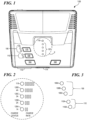
FIGURE 1 is a top-down view of a first embodiment of a battery charger; -
FIGURE 2 is a detail view showing the status indicators of a battery charger according to the embodiment ofFig. 1 ; -
FIGURE 3 is a detail view showing charging parameter selection indicators of a battery charger according to the embodiment ofFig. 1 ; -
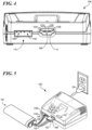
FIGURE 4 is a front view of a battery charger according to the embodiment ofFig. 1 ; -
FIGURE 5 is a perspective view of a battery charger according to the embodiment ofFig. 1 ; -
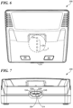
FIGURE 6 is a top-down view of a second embodiment of a battery charger; -
FIGURE 7 is a front view of a battery charger according to the second embodiment ofFig. 6 ; -
FIGURE 8 is a perspective view of a battery charger according to the second embodiment ofFig. 6 ; -
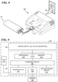
FIGURE 9 is a block diagram of exemplary system components of a battery charger; -
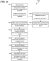
FIGURE 10 is a flowchart showing system operation of a battery charger; -
FIGURE 11 is a flowchart illustrating a mode of operation of a battery charger; -
FIGURE 12 is a flowchart illustrating a mode of operation of a battery charger; -
FIGURE 13 is a flowchart illustrating a mode of operation of a battery charger; -
FIGURE 14 is a flowchart illustrating a mode of operation of a battery charger; -
FIGURE 15 is a flowchart illustrating a mode of operation of a battery charger; -
FIGURE 16 is a flowchart illustrating a mode of operation of a battery charger; -
FIGURE 17 is a flowchart illustrating a mode of operation of a battery charger; -
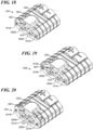
FIGURES 18 - 20 are a perspective views of female electrical connectors having certain keying features; and -
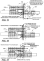
FIGURE 21 - 23 are side, phantom views of male and female electrical connectors illustrating three stages of mating. - In the following discussion, numerous specific details are set forth to provide a thorough understanding of the present invention. However, the present invention may be practiced without such specific details. In other instances, well-known elements have been illustrated in schematic or block diagram form in order not to obscure the present invention in unnecessary detail. Additionally, and for the most part, details concerning well-known features and elements have been omitted inasmuch as such details are not considered necessary to obtain a complete understanding of the present invention. Specifically, details concerning electronic communications, electro-magnetic signaling techniques, RFID, battery charge current generation and control, methods of battery charging, and the like, have been omitted.
- A single battery charger may accommodate rechargeable batteries of different chemistries, such as accommodating both Li-type and Ni-type batteries, for example. The battery charger may be configured to implement charge parameter settings received from a coupled battery to be charged. The battery charger may also be configured to implement default charge parameter settings in response to detected conditions. The battery charger may also be configured to receive user input for adjusting and/or entering charge parameter settings.
- Lithium Polymer (LiPo) batteries equipped with RFID technology and integrated balance taps may communicate with a device such as a battery charger equipped with similar technology providing information such as chemistry type, cell count, recommended charge rates, number of charges on the battery, among other types of information. Safety features may include:
- the ability for the RFID tag to program a charger once the tag is read, allowing for single push-button charging; an integrated balance tap may reduce the need for multiprocess charging setups;
- the balance taps may be used in conjunction with the RFID tag information to add additional layers of battery cell type confirmation;
- a short antenna range on the RFID reader may reduce interference from surrounding items;
- the RFID reader may read and register one tag to reduce errors in information transfer; and
- the system may be designed to read RFID tag information before an electrical connection is made. For example, reading the RFID tag information may be pre-requisite to charging an RFID. In an embodiment, the RFID reader may see the RFID tag before the positive and negative terminals of the connector make contact with a paired device, such as a battery charger, for example.
- In an embodiment, a
battery charger 100 according to the present invention may comprise a charger output port for coupling with a battery to be charged, a sensor device and reader for receiving information from the battery to be charged, one or more balance ports for balance charging, a plurality of switches for receiving user input, a plurality of status indicators, and a plug for connecting the battery charger to a power supply. In alternative embodiments the battery charger may be provided with additional, fewer, or different components. - The
battery charger 100 may be configured to be compatible with rechargeable batteries of several types. For example, the battery charger may be configured to be capable of charging both NiMH type and LiPo type batteries. Thebattery charger 100 may further be configured to be capable of charging different sized batteries of each type. For example, in a specific embodiment, thebattery charger 100 may be configured to be compatible with NiMH batteries of either 2/3A or Sub-C sizes, as well as LiPo battery packs of 2S and 3S sizes. - The listed examples are intended to be illustrative only. In alternative embodiments, the
battery charger 100 may be configured to be capable of charging batteries of different types and sizes than those listed above. Specifics regarding each battery type and size are omitted from this description as such details are not considered necessary to obtain a complete understanding of the present invention, and are considered to be within the understanding of persons of ordinary skill in the relevant art. - As shown in
Figs. 1 and4 , in an embodiment, abattery charger 100 may comprise acharger output port 114 for electrically coupling a rechargeable battery to thebattery charger 100. In an embodiment, thecharger output port 114 may be an electrical connector such as an electrical socket or receptacle for receiving an electrical plug coupled to a battery to be charged, for example. According to the embodiment shown, thecharger output port 114 may comprise an electrical socket comprising an insulating material and implemented with twomale terminals electrical connector 152 of arechargeable battery 150. In an embodiment, thecharger output port 114 may be provided withbalancing terminals LiPo Balancing Circuit 312, shown inFig. 9 . Thebattery charger 100 may be configured to provide a charging current to a rechargeable battery through thecharger output port 114 upon user initiation of charging operation while the rechargeable battery is electrically connected to thecharger output port 114. - In an embodiment, the
battery charger 100 may be configured to be compatible with only batteries of one or more specific types. The socket shape of theoutput charge port 114 may be implemented with one or more keying features for preventing incompatible batteries from electrically coupling with thebattery charger 100. Specific keying features that may be provided are discussed further inU.S. Provisional Patent Application, Ser. No. 62/007,403 filed on June 3, 2014 - Female electrical connector housings, having various keying and coupling features, are now described. A battery to be charged may be implemented with a female connector implemented with a female connector having a
housing 1802, 1902, or 2002, and implemented with one or more of the features described below. Thecharger output port 114 may be configured to be compatible with female connector housings of the types described below. Thebattery charger 100 may be configured with acharger output port 114 which may be a socket implemented with one or more features corresponding to features of the female connector housings described. Specifically, thecharger output port 114 may be implemented with complimentary keying features, balance tab, or terminal, features, and an RFID communication device, or devices, to those of thefemale connector housings 1802, 1902, and 2002. Thebattery charger 100 may, therefore, be configured to receive and charge a battery having female connector housings implemented with none, some, or all of the keying features and balance terminals described below in reference tohousings 1802, 1902, and 2002. - Turning now to
Fig. 18 , a femaleelectrical connector 152C may include ahousing 1802. The housing may have anelevated structure 1820 on a top side of theconnector 152A and adjacent one end of theconnector housing 1802. Theelevated structure 1820 may partially enclose acavity 1807 for receiving anRFID tag 206, as shown inFig. 1-3 . Adjacent the same end of thehousing 1802 as thecavity 1807 there may be provided first and secondmain receptacles housing 1802 there may also be provided first andsecond channels balancing terminals Fig. 4 . Akeying feature 1810 may be provided in thehousing 1802, and may comprise a V-shaped groove running along the center of a bottom side of the connector 1800, for example. - Turning now to
Fig. 19 , a femaleelectrical connector 152B has a housing 1902 as described hereinbefore. The housing may have anelevated structure 1920 on a top side of theconnector 152B and adjacent one end of the connector housing 1902. Theelevated structure 1920 may partially enclose acavity 1907 for receiving anRFID tag 206, as shown inFig. 1-3 . Adjacent the same end of the housing 1902 as the cavity 207 there may be provided first and secondmain receptacles second channels balancing terminals Fig. 4 . Afirst keying feature 1910 may be provided in the housing 1902, and may comprise a V-shaped groove running along the center of a bottom side of theconnector 152B, for example. Asecond keying feature 1912B may be provided, for example, on a top side of theconnector 152B, and may be a protrusion extending from one side ofelevated structure 1920 in the direction ofreceptacle 1905B andchannel 1914B. - Turning now to
Fig. 20 , a femaleelectrical connector 152C has a housing 2002 as described hereinbefore. The housing may have anelevated structure 2020 on a top side of theconnector 152C and adjacent one end of the connector housing 2002. Theelevated structure 2020 may partially enclose acavity 2007 for receiving anRFID tag 206, as shown inFig. 1-3 . Adjacent the same end of the housing 2002 as the cavity 207 there may be provided first and secondmain receptacles 2005 and 2005B, respectively. Adjacent the same end of the housing 2002 there may also be provided first andsecond channels balancing terminals Fig. 4 . A first keying feature 2010 may be provided in the housing 2002, and may comprise a V-shaped groove running along the center of a bottom side of the connector 200A. Asecond keying feature 2012A may be provided, for example, on a top side of theconnector 152C, and may be a protrusion extending from one side ofelevated structure 2020 in the direction ofreceptacle 2005A andchannel 2014A. - The
charger output port 114 may be implemented with asensor device 309, which may be coupled to anRFID reader 308, and which may be disposed along an inner surface of the electrical socket ofcharger output port 114. In an embodiment, thesensor device 309 may be an antenna coupled to theRFID reader 308 for receiving and transmitting data to theRFID reader 308. In some embodiments, thesensor device 309 and theRFID reader 308 may comprise a single component. - The
output charge port 114 may comprise a socket composed of an insulating material. The insulating material of the socket may extend over an exposed length of themale terminals RFID reader 308 and/orsensing device 309 may be disposed within the portion of the inner surface of the socket extending along the exposed length of the male terminals. Specific details regarding the location of theRFID reader 308 andsensing device 309 within the socket of thecharge output port 114 may be found inU.S. Provisional Patent Application, Ser. No. 62/007,403 filed on June 3, 2014 - Turning now to
Figures 21 - 23 , a maleelectrical connector 2100 is shown in a phantom view engaging with a femaleelectrical connector 2200, also shown in phantom view. An RFID equipped battery may comprise a femaleelectrical connector 2200. An RFID equippedbattery charger 100 may comprise a maleelectrical connector 2100. The maleelectrical connector 2100 may comprise aninsulated housing 2102 containing at least one male electrical terminal 2104 extending from a portion of thehousing 2102. In an embodiment, there may be two maleelectrical terminals 2104 for connecting to positive and negative electrical circuits, respectively. Thehousing 2102 may extend over an exposed length of the maleelectrical terminals 104, theextended portion 2103 for enclosing anRFID reader 308 and/orsensing device 309. It is well understood that theRFID reader 308 may be electrically connected to a smart device by suitable wiring (not shown). The maleelectrical terminals 2104 may be coupled to high-current capacity wiring 2108, such as 12AWG wires, for example. - The female
electrical connector 2200 may comprise aninsulated housing 2202 containing at least one female electrical terminal 2204 partially enclosed within areceptacle portion 2205 of thehousing 2202. In an embodiment, there may be two femaleelectrical terminals 2204 each at least partially enclosed within its own,separate receptacle portion 2205, for connecting to positive and negative electrical circuits, respectively. Thehousing 2202 may enclose anRFID tag 206. The femaleelectrical terminals 2204 may be coupled to high-current capacity wiring 2208, such as 12AWG wires, for example. - When an RFID equipped battery is starting to be coupled to an RFID equipped charger, the
RFID tag 206 andRFID reader 308 may establish an RF connection and start to communicate and transmit information, as illustrated inFig. 21 . As theelectrical connectors RFID tag 206 andRFID reader 308 have established an RF connection. Alternatively, theRFID reader 308 may not attempt to establish communications with theRFID tag 206 until electrical connection is made. Either way, theRFID tag 206 can be expected to be within range of theRFID reader 308 and/or orsensing device 309, when an electrical connection is made. At this point, the battery charger may be enabled to operate. - The connector may be configured such that the
RFID tag 206 may establish an RF connection withRFID reader 308 before an electrical connection is made to prevent improper usage of an RFID equipped battery, as illustrated inFig. 22 . If theconnectors Fig. 23 . In an embodiment, theRFID reader 308 may read theRFID tag 206 when the male andfemale connectors RFID tag 206 is enclosed withinhousing 2202, and may continue to read while the male andfemale connectors RFID reader 308 may be configured to read theRFID tag 206 located in other positions relative to thefemale connector 2200, such as being mounted on an exterior surface of the connector, for example, or any other suitable location. - In an embodiment, the
battery charger 100 may be configured to electrically couple with batteries comprising a female electrical connector that may comprise an insulated housing and two female terminals. Thebattery charger 100 may be further configured to electrically couple with batteries having a female connector further comprising anRFID tag 206. In such an embodiment, the battery charger may be configured to also be compatible with batteries having a female connector not comprising anRFID tag 206. In such an embodiment, the battery charger may be configured to respond in a different manner when electrically coupled to a battery implemented with anRFID tag 206 than the manner that thebattery charger 100 is configured to respond when electrically coupled to a battery without anRFID tag 206, as described later in this specification. - The
RFID reader 308 and/orsensing device 309 may be disposed within the socket of theoutput charge port 114 and female electrical connector, respectively, such that theRFID tag 206 may be within range of theRFID reader 308 and/orsensing device 309 during and while an electrical connection is made between the battery and thebattery charger 100. An RF connection may be established as the female electrical connector of a battery is inserted into the socket of thecharge output port 114. The RF connection may be maintained during the time in which the female electrical connector of the battery is electrically coupled to thebattery charger 100. - The
RFID reader 308 may be configured to attempt to establish communications with theRFID tag 206 upon sensing theRFID tag 206 or, alternatively, only after an electrical connection is made between the battery and thebattery charger 100. In an embodiment, thebattery charger 100 may enable charging of an RFID equipped battery only after an RF connection is made, to prevent improper charging of the RFID equipped battery. - When an RFID equipped battery is coupled to the RFID equipped
battery charger 100, theRFID tag 206 andRFID reader 308 and/orsensing device 309 may establish an RF connection and start to communicate and transmit information to an RFID reader. Information contained on theRFID tag 206 may comprise a manufacturer assigned identifier number, or code, unique to the specific battery model, or unique to the battery, itself. Additionally, in alternative embodiments, further information such as chemistry type, cell count, recommended charge rates, number of charges on the battery, among other information, may be contained on theRFID tag 206 and read by theRFID reader 308 and/orsensing device 309 ofbattery charger 100. Thebattery charger 100 may use the information received to configure the charge current and charge operation of thebattery charger 100, allowing for single push-button charging of batteries having a recognizedRFID tag 206. - As shown in
Figs. 1 ,4, and 5 , thebattery charger 100 may be implemented withbalance connector ports balance connector ports battery charger 100 for use during balance charging of a Lithium-type battery, such as a LiPo battery, for example. - In the particular embodiment shown, the battery charger may implemented with two
balance connector ports balance connector port 116A may be configured to accommodate a 2S LiPo battery, while thebalance connector port 116B may be configured to accommodate a 3S LiPo battery. In alternative embodiments, thebattery charger 100 may be implemented with additional, or fewer,balance connector ports 116. Further, in an alternative embodiment, thebattery charger 100 may be implemented with balance connector ports of different sizes for accommodating larger LiPo batteries. - As shown in
Fig. 5 , in an embodiment, thebattery charger 100 may be configured to receive both a female electrical connector and a balance connector of the battery to be charged when balance charging a LiPo battery. In an embodiment, thebattery charger 100 may be configured to electrically couple to a 2S balance connector using thebalance connector port 116A. In such an embodiment, thebattery charger 100 may be further configured to electrically couple to a 3S balance connector using thebalance connector port 116B. - In some embodiments, the
battery charger 100 may be implemented with logic for adjusting one or more charger settings, such as the Battery Type, the Charge Mode, or the Charge Rate, each of which are described below, in response to a balance connector being electrically coupled to one of thebalance connector ports 116 of thebattery charger 100. For example, abattery charger 100 implemented with a Battery Type selector may be configured to set the Battery Type to "LiPo" in response to a balance connector being electrically coupled to one of thebalance connector ports 116. Further, abattery charger 100 implemented with a Charge Type selector may be configured to set the Charge Type to "Balance" in response to a balance connector being electrically coupled to one of thebalance connector ports 116. Abattery charger 100 implemented with a Charge Rate selector may be configured to set the Charge Rate to a pre-determined value, such as "4A", for example, in response to a balance connector being electrically coupled to one of thebalance connector ports 116. - According to embodiment shown in
Fig. 1 , abattery charger 100 may comprise four switches: afirst switch 102, asecond switch 104, athird switch 108, and afourth switch 112. Each switch may receive user input to set one or more charging parameters of thebattery charger 100. As shown inFig. 1 , each switch may comprise a push button. In alternative embodiments, the switches may comprise any combination of push buttons, toggle switches, radial switches, and the like. Further, in an alternative embodiment, the battery charger may be implemented with additional or fewer switches than shown inFig. 1 or, alternatively, may be implemented with switches incorporated into a touch screen display. - As shown in
Fig. 1 , thefirst switch 102 of thebattery charger 100 may be a push button switch providing the user "start / stop" control over the delivery of a charging current by thebattery charger 100. Thefirst switch 102 may be configured to initiate delivery of a charging current by thebattery charger 100 to a battery to be charged, starting charging of the battery, upon depression of thefirst switch 102 by the user. In addition, thefirst switch 102 may be configured to terminate delivery of a charging current to a battery to be charged, thereby stopping charging of the battery, upon a subsequent depression of thefirst switch 102 by the user. In this manner, thefirst switch 102 may be used by the user to toggle thebattery charger 100 between charging and non-charging operation. In an embodiment, thefirst switch 102 may be configured to toggle thebattery charger 100 between charging and non-charging operation in response to thefirst switch 102 being held in the depressed position for a specified amount of time, for example, two seconds. - The
first switch 102 may also be configured to operate as a status indicator, illuminating to indicate a status or condition of thebattery charger 100. Thefirst switch 102 may comprise a material configured to allow light to pass through it and be positioned over a light emitting diode (LED) housed within thebattery charger 100. Upon the occurrence of a specific status or condition of thebattery charger 100, the LED may be illuminated, causing thefirst switch 102 to illuminate and indicating to the user the occurrence of a status or condition of thebattery charger 100. - In an embodiment, for example, the
first switch 102 may illuminate during times when thebattery charger 100 has received information from a battery to be charged through a sensor device of thebattery charger 100. In a particular embodiment, the battery to be charged may be comprise an RFID chip, for example, with thefirst switch 102 configured to illuminate in response to thebattery charger 100 receiving the information contained on the RFID chip of the battery to be charged. In such an embodiment, thefirst switch 102 may be further configured to not illuminate, or, alternatively, illuminate in a second mode, perhaps in a different color or flashing on and off, for example, when a battery is electrically coupled to the battery charger and no information is received by the sensor from the battery to be charged. - As shown in
Fig. 1 , thebattery charger 100 may be implemented with asecond switch 104 which may be a push button switch for allowing the user to select a "Charge Rate." The Charge Rate selected may set the amperage (A) of the charge current to be provided by thebattery charger 100 to a battery to be charged. As shown in the embodiment ofFig. 1 , thebattery charger 100 may be configured with four "Charge Rate" options: 1A; 2A; 3A; or 4A. In an alternative embodiment, thebattery charger 100 may be implemented with additional, or fewer, Charge Rates with larger, or smaller, steps between adjacent selection amperage values. In a further alternative, the Charge Rate may be selected from a continuous range of amperage values. - The
second switch 104 may be configured to cycle through the Charge Rate options, incrementally changing the selection with each press of thesecond switch 104 by the user. In an alternative embodiment, thesecond switch 104 may be a toggle switch, radial switch, or the like, with the user moving thesecond switch 104 to the position corresponding to a desired mode selection. - The
battery charger 100 may also be configured with default settings implemented in response to a battery of a specific battery chemistry being connected to thebattery charger 100. For example, thebattery charger 100 may be configured to default to the "4A" Charge Rate setting when thebattery charger 100 detects that a NiMH battery is connected to thebattery charger 100. In such an embodiment, thebattery charger 100 may be configured to detect the NiMH-type battery through information received from the connected battery through a sensor device of thebattery charger 100, or, alternatively, in response to user selection of the NiMH Battery Type using thethird switch 108, as described above. - The
battery charger 100 may be implemented with logic for allowing the user to "unlock" thebattery charger 100, allowing the user to override or input charge parameter settings while a battery is coupled to thebattery charger 100. This may be regarded as using thebattery charger 100 in "Advanced Mode." Thebattery charger 100 may be implemented with logic for entering "Advanced Mode" in response to a specific user action, such as pressing and holding both the "Start / Stop" and "Charge Rate" pushbuttons simultaneously for 2 seconds, for example. Further, thebattery charger 100 may be configured to indicate that "Advanced Mode" has been entered, such as by causing one ormore indicators 120 to flash, for example. Specific instances when "Advanced Mode" may be used and the capabilities "unlocked" by entering "Advanced Mode" are described later in this description. - As shown in
Fig. 1 , thebattery charger 100 may be implemented with athird switch 108 which may be a push button switch for allowing the user to select a "Battery Type." Thethird switch 108 may be configured to cycle through the available types, incrementally changing the selection with each press of thethird switch 108 by the user. In an alternative embodiment, thethird switch 108 may be a toggle switch, radial switch, or the like, with the user moving thethird switch 108 to the position corresponding to a desired type selection. - As shown in
Fig. 1 , thebattery charger 100 may be configured with two "Battery Type" options: Lithium-polymer ("LiPo") and Nickel-metal hydride ("NiMH"). In alternative embodiments, thebattery charger 100 may be implemented with additional, or fewer, Battery Types. For example, the battery charger may be configured to charge rechargeable batteries of other known chemistries comprising the prior art, such as Lithium-iron (LiFe), Lithium-ion, Nickle-cadmium (NiCd), and the like. - The
battery charger 100 may be configured with default settings implemented in response to a battery of a specific type being connected to thebattery charger 100. For example, thebattery charger 100 may be configured to default to the LiPo type in response to receipt of a balance port connector at a balance port of thebattery charger 100. - As shown in
Figs. 1 and 3 , thebattery charger 100 may be implemented with one or more BatteryType selection indicators battery charger 100 may be configured to illuminate the LED corresponding to the currently selected Battery Type. In an alternative embodiment, additional, fewer, or no BatteryType selection indicators 110 may be provided. For example, in an embodiment utilizing a radial switch for Battery Type selection, no Battery Type selection indicators may be provided. In another embodiment, asingle indicator 110 may be provided and configured to illuminate a different color corresponding to each of the possible Battery Types. - As shown in
Fig. 1 , thebattery charger 100 may be implemented with afourth switch 112 which may be a push button switch for allowing the user to select a "Charge Mode." Thefourth switch 112 may be configured to cycle through the available modes, incrementally changing the selection with each press of thefourth switch 112 by the user. In an alternative embodiment, thefourth switch 112 may be a toggle switch, radial switch, or the like, with the user moving thefourth switch 112 to the position corresponding to a desired mode selection. - As shown in
Fig. 1 , thebattery charger 100 may be configured with three "Charge Mode" options: Store, Fast, and Balance. Store mode may charge or discharge a battery connected to thebattery charger 100 to bring the battery to a storage voltage and may be used for preparing a battery for a period of nonuse. Fast mode may charge a battery to the peak voltage of the battery. Charging in fast mode may terminate upon the first cell of a multi-cell battery reaching the peak voltage. Balance charge may charge a multi-cell battery to a peak voltage while maintaining uniform charge among the multiple battery cells. For each of the above-described modes, charging or discharging may be accomplished through peak voltage detection, through constant-voltage and constant-current (CVCC) charging, or any other known methods of battery charging comprising the prior art. In an embodiment, thebattery charger 100 may be implemented with additional, or fewer, Charge Modes. - Further, in an embodiment, the
battery charger 100 may be configured to allow selection of one or more of the Charge Modes only when a battery of a specific chemistry is to be charged. For example, thebattery charger 100 may be configured to prevent selection of "balance" charge unless a Lithium polymer (LiPo) type battery is connected to thebattery charger 100. Further, thebattery charger 100 may be configured to enable the Charge Mode function when a battery of a specific type is to be charged. For example, thebattery charger 100 may utilize the Charge Mode selection function only when a LiPo type battery is to be charged, with the Charge Mode selection function not configured to be used when the NiMH Battery Type is selected. In an embodiment according to the last example, the "Charge Mode" button may be implemented with "LIPO" label to indicate the Charge Mode is only configurable at times when a LiPo type battery is connected to thebattery charger 100. - The
battery charger 100 may also be configured with default settings implemented in response to a battery of a specific battery chemistry being connected to thebattery charger 100. For example, thebattery charger 100 may be configured to default to the Balance Charge Mode when thebattery charger 100 detects that a LiPo battery is connected to thebattery charger 100. In such an embodiment, thebattery charger 100 may be configured to detect the LiPo-type battery through information received from the connected battery through a sensor device of thebattery charger 100, or, alternatively, in response to receipt of a balance port connector at a balance port of thebattery charger 100. - As shown in
Figs. 1 and 3 , thebattery charger 100 may be implemented with one or more ChargeMode selection indicators 106A-C, which may be LEDs, for indicating the Charge Mode selected. Thebattery charger 100 may be configured to illuminate the LED corresponding to the currently selected Charge Mode. In an alternative embodiment, additional, fewer, or no ChargeMode selection indicators 106 may be provided. For example, in an embodiment utilizing a radial switch for Charge Mode selection, no Charge Mode selection indicators may be provided. In another embodiment, asingle indicator 106 may be provided and configured to illuminate a different color corresponding to each of the possible Charge Modes. - As shown in
Figs. 1 and 2 , thebattery charger 100 may be implemented with one ormore indicators indicators indicators - According to the embodiment shown, the
battery charger 100 may be implemented with aCharge Status indicator 118 comprising a single LED. In such an embodiment, the Charge Statues indicator may be configured to illuminate in one or more modes for indicating different statuses of thebattery charger 100. In an embodiment, the charge mode indicator may illuminate in a first mode during at least a portion of the charging mode and in a second mode when charging is completed, for example. In an embodiment, the mode indicator may illuminate in a third mode if no information is received by the sensor when the electrical connector is coupled to the battery to be charged, for example. In an alternative embodiment, more than oneCharge Status indicator 118 may be provided, with the illumination pattern of the one ormore indicators 118 indicating abattery charger 100 status. - In an exemplary embodiment implemented with a single LED
Charge Status indicator 118, theCharge Status indicator 118 may be configured to flash on and off during times when thebattery charger 100 is providing a charging current to a battery to be charged. In such an embodiment, theCharge Status indicator 118 may be further configured to remain illuminated upon completion of charging of a battery. In alternative embodiments, different modes of illumination may be provided to indicate one or more Charge Statuses to the user. For example, the color of light emitted by theCharge Status indicator 118 may vary to indicatedifferent battery charger 100 statuses. - According to the embodiment shown in
Figs. 1 and 2 , thebattery charger 100 may be implemented with a plurality ofindicators 120, which may be LEDs, for indicating the Charge Rate and/or the Charge Progress. In an embodiment, the chargingstatus indicators 120A-120D may be a plurality of light emitting devices illuminating in succession to indicate the amount of electrical charge delivered to a battery to be charged, for example. As noted above, the Charge Rate may be the amperage of the charging current provided by thebattery charger 100 to a battery. The Charge Progress may be an indication of the current charge level of the battery being charged. The Charge Progress may be displayed as a ratio, or percentage, of current charge to peak charge or, alternatively, may be displayed as symbols indicating a progressive increase in charge amount. - As shown, the
battery charger 100 may comprise four Charge Rate /Progress indicators 120A-D. Each Charge Rate /Progress indicator 120 may be implemented with one or more labels, as shown inFig. 2 , specifying a Charge Rate and/or Charge Progress value. For example,indicator 120A may be provided with a "1A" label for indicating a 1 amp Charge Rate as well as a symbol indicating a relative amount of charge contained by a battery being charged, the Charging Progress. In alternative embodiments, thebattery charger 100 may be implemented with more, orfewer indicators 120 configured to indicate additional, fewer, or different statuses or conditions of thebattery charger 100. - During times when the
battery charger 100 is connected to a battery but is not providing a charging current, thebattery charger 100 may be configured to indicate the selected Charge Rage by illuminating the Charge Rate /Progress indicator 120A-D corresponding to the selected Charge Rate. Thebattery charger 100 may be further configured to illuminate the Charge Rate /Progress indicators 120 to indicate the currently selected Charge Rate only during times when thebattery charger 100 has received information from the battery through the sensor device and prior to commencement of providing a charging current to the battery. At such times theCharge Rate indicator 120A-D illuminated may change with each press of thefourth switch 112 by the user, cycling through the Charge Rate options as described above. - In some embodiments, the
battery charger 100 may be implemented with logic permitting the Charge Rate selected to be indicated to the user during charging of a battery. In such embodiments, thebattery charger 100 may be configured to illuminate only the Charge Rate /Progress indicator 120 corresponding to the currently selected Charge Rate in response to user input during charging, such as in response to the user pressing the "Charge Rate" button during charging, for example. Thebattery charger 100 may be configured to display the current Charge Rate in the manner described above for a specified period of time, such as for five seconds, perhaps. In addition, thebattery charger 100 may be configured to illuminate theCharge Status indicator 118 in a solid mode during the time in which the Charge Rate selection may be indicated during charging of a battery. - The
battery charger 100 may be further configured to indicate the Charge Progress at times when thebattery charger 100 is providing a charging current to a battery through illumination of the Charge Rate / Progress indicator, or indicators, 120A-D corresponding to the amount of charge contained the battery being charged. For example, and according to the embodiment shown, during a complete charging of a battery having no charge initially, the Charge Rate /Progress indicators 120A-D may illuminate in succession withindicator 120A illuminating first, indicating the battery has little or no charge, perhaps with the battery charge being below 20% of the peak voltage charge. As the battery charge increases during charging,additional indicators 120 may illuminate. According to the present example,indicators indicator 120C may illuminate upon the battery charge reaching 60% of peak voltage and 120D at 80%. At full charge, thebattery charger 100 may be configured to illuminate theCharge Status indicator 118 according to a specific mode, or pattern, as described above. - The
Charge Status indicator 118 and Charge Rate /Progress indicators 120A-D may be further configured to illuminate in an alternative manner, such as sweeping back-and-forth or collectively flashing, for example, at times when thebattery charger 100 is connected to a battery and thesensor device 309 has not received any information from the battery. Additionally, the Charge Rate /Progress indicators 120A-D may be configured to illuminate in a specific mode at start up for indicating to a user that thebattery charger 100 is powered up and waiting to be coupled to a battery to be charged. For example, thebattery charger 100 may be configured to illuminate the Charge Rate /Progress indicators 120A-D in a "runway" pattern at start up, or, additionally, at any time that the battery charger is capable of charging and awaiting coupling to a battery to be charged, such as upon disconnection of a battery that has just been charged. - The
battery charger 100 may be implemented with logic for displaying error codes to a user through illumination of theindicators TABLE 1 - ERROR CODES ILLUMINATION MODE ERROR EXPLANATION SOLUTION: 120D, flashing Detected battery type does not match the Battery Type selection Press the START/STOP/ button; verify the battery matches the selected type; verify balance connector is plugged in (if required) 120C, flashing Battery or cell voltage is too high or too low to charge safely Verify balance connector is plugged in (if required); disconnect battery and check condition 120B, flashing Charge cycle timed out without reaching the target battery voltage. Disconnect battery and check condition. 120A, flashing A preferred battery iD is detected but not readable by the battery charger. Contact customer support 120B-D, flashing The battery charger internal temperature is too high. Power off the battery charger to allow charger to cool off. - As shown in
Fig. 5 , thebattery charger 100 may be implemented with aplug 126 for operably connecting thebattery charger 100 to an external power supply. In the embodiment shown, theplug 126 may comprise a standard A/C plug for insertion into a wall outlet. - Additionally, in some embodiments, the
battery charger 100 may be implemented with an audible enunciator device (not shown), such as a speaker. In such embodiments, the audible enunciator device may be configured to alert the user of changes in a status or condition of thebattery charger 100. For example, thebattery charger 100 may be implemented with a speaker for making a sound, such as a tone, beep, or the like, to indicate that thebattery charger 100 has completed charging a battery. Additionally, the speaker may be configured to produce alternative sounds for indicating other statuses, or conditions, of thebattery charger 100 such as error alert tones or beeps indicating a change to a charging operation parameter. - Referring now to
Figs. 6 - 8 , a second embodiment of a battery charger is shown. Thebattery charger 200 may be configured to be compatible with batteries of a specific battery chemistry type. For example, thebattery charger 200 may be configured to charge only NiMH type batteries. Accordingly, thebattery charger 200 may be a "simplified" version of thebattery charger 100 and may be implemented with fewer components than thebattery charger 100. - The
battery charger 200 may comprise acharger output port 214 for coupling thebattery charger 200 to a rechargeable battery, asensor device 309 for receiving information from the battery to be charged, twoswitches status indicators plug 226 for connecting the battery charger to a power supply. - As shown in
Fig. 7 , thebattery charger 200 may comprise acharger output port 214 for electrically coupling a rechargeable battery to thebattery charger 200. According to the embodiment shown, thecharger output port 214 may comprise an electrical socket comprising an insulating material and implemented with two male terminals for receiving a female electrical connector (not labeled) of a rechargeable battery. Thecharger output port 214 may be further implemented with asensor device 309, which may be an RFID reader, and which may be disposed along an inner surface of the electrical socket ofcharger output port 214. Thebattery charger 200 may be configured to provide a charging current to a rechargeable battery through thecharger output port 214 upon user initiation of charging operation while the rechargeable battery is electrically connected to thecharger output port 214. - According to embodiment shown in
Fig. 1 , thebattery charger 200 may comprise two switches: afirst switch 202 and asecond switch 204. Both switches 202, 204 may receive user input to set one or more charging parameters of thebattery charger 200 and/or initiate deliver of a charging current by thebattery charger 200. As shown inFig. 6 , each switch may comprise a push button. In alternative embodiments, the switches may comprise any combination of push buttons, toggle switches, radial switches, and the like. - As shown in
Fig. 6 , thefirst switch 202 of thebattery charger 200 may be a push-button switch providing the user "start / stop" control over the delivery of a charging current by thebattery charger 200. Thefirst switch 202 may also be configured to operate as a status indicator, illuminating to indicate a status or condition of thebattery charger 200. - The
first switch 202 of thebattery charger 200 may have substantially similar construction and features as the correspondingfirst switch 102 of thebattery charger 100, described above. Further, thefirst switch 202 of thebattery charger 200 may perform substantially the same functions as the correspondingfirst switch 102 of thebattery charger 100, described above. As such, specific features of thefirst switch 202 will not be described herein, but are instead, described through reference to the description of thefirst switch 102, above. The convention of describing thefirst switch 102 in this manner is adopted for the purpose of avoiding unnecessary and repetitive language, only, and shall not foreclose from the scope of this disclosure a wide range of variations, modifications, changes and substitutions expressly, or implicitly, disclosed here. - As shown in
Fig. 6 , thebattery charger 200 may be implemented with asecond switch 204 which may be a push button switch for allowing the user to select a "Charge Rate." Thesecond switch 204 of thebattery charger 200 may have substantially similar construction and features as the correspondingsecond switch 104 of thebattery charger 100, described above. Further, thesecond switch 204 of thebattery charger 200 may perform substantially the same functions as the correspondingsecond switch 104 of thebattery charger 100, described above. As such, specific features of thesecond switch 204 will not be described herein, but are instead, described through reference to the description of thesecond switch 104, above. The convention of describing thesecond switch 204 in this manner is adopted for the purpose of avoiding unnecessary and repetitive language, only, and shall not foreclose from the scope of this disclosure a wide range of variations, modifications, changes and substitutions expressly, or implicitly, disclosed here. - As shown in
Fig. 6 , thebattery charger 200 may be implemented with one ormore indicators indicators indicators - As shown in
Fig. 6 , thebattery charger 200 may be implemented with acharger output port 214 for electrically coupling a rechargeable battery to thebattery charger 200. In an embodiment, thecharger output port 214 may be an electrical connector such as an electrical socket or receptacle for receiving an electrical plug coupled to a battery to be charged, for example. According to the embodiment shown, thecharger output port 214 may comprise an electrical socket comprising an insulating material and implemented with twomale terminals electrical connector 152 of arechargeable battery 150. In an embodiment, thecharger output port 214 may be provided with balancing terminals 224A and 224B, which connect toLIPO Balancing Circuit 312, as shown inFig. 9 . The balancing terminals may not be utilized when charging other than LiPo batteries. - The
indicators battery charger 200 may have substantially similar construction and features as the correspondingindicators battery charger 100, described above. Further, theindicators battery charger 200 may perform substantially the same functions as the correspondingindicators battery charger 100, described above. As such, specific features of theindicators indicators indicators - Referring now to
Fig. 9 , a block diagram of exemplary internal components of thebattery charger 100 is shown. Thebattery charger 100 may comprise acontroller 300, anRFID sensor 309, one ormore balancing circuits 312, a chargingcircuit 306,power supply circuitry 302, and afan 314. - As shown in
Fig. 9 , in an embodiment, thepower supply circuit 302 may be an AC to DC converter circuit for converting AC current received by thebattery charger 100 to DC current. Thepower supply circuit 302 may comprise any known components or methods for power conversion comprising the prior art that may be suitable for use in a battery charger having the capabilities described in reference to thebattery charger 100, herein. - As shown in
Fig. 9 , in an embodiment, the chargingcircuit 306 may be operably connected to thepower supply circuit 302 and may be configured to provide a charge current for charging a battery in accordance with desired charging parameter settings. The chargingcircuit 306 may comprise any known components or methods for configuring the DC current received from thepower supply circuit 302 comprising the prior art that may be suitable for use in a battery charger having the capabilities described in reference to thebattery charger 100, herein. The chargingcircuit 306 may be capable of configuring a charge current suitable for charging batteries of the type and size described herein and in accordance with known charging methods, such as: peak voltage detection charging; constant voltage constant current charging; trickle charging; balance charging; storage charging; and the like. - The
controls components 300 may include anRFID reader 308 for establishing RF communication with batteries implemented with an RFID tag, to receive data from the battery for use in configuring the charge current provided by thebattery charger 100. TheRFID reader 308 may be operably connected to aprocessor 318 and/or an interface I/O 310 and may communicated data received from a battery implemented with an RFID tag to those components. TheRFID reader 308 may be of the type and have the functional capabilities as described inU.S. Provisional Patent Application, Ser. No. 62/007,403 filed on June 3, 2014 - The interface I/
O 310 may receive and route data from and between the components comprising thecontrols components 300 of thebattery charger 300. The interface I/O may operably connect to any other components comprising thecontrols components 300 through any operable connection methods comprising the prior art for sending and/or receiving signals, physical communications, and/or logical communications. In a particular embodiment, the interface I/O 310 may be configured to receive data from theRFID reader 308 and direct the received data to other components, such as theprocessor 318, the chargingcircuit 306, aLiPo balancing circuit 312, or the like. In an alternative embodiment, thecontrols components 300 may not include an interface I/O 310. In such embodiments, the components comprising thecontrols components 300 may be configured to communicate directly through wired or wireless connections between the components. - As shown in
Fig. 9 , thecontrols components 300 may include one or moreLiPo balancing circuit 312 for providing low amperage balance charge currents for use in charging LiPo type batteries. TheLiPo balancing circuits 312 may operably connect to other components such as theRFID reader 308, the interface I/O 310, the chargingcircuit 306, thepower supply circuit 302, thememory 316, and/or theprocessor 318. TheLiPo balancing circuits 312 may comprise any known components or methods for balance charging a LiPo battery comprising the prior art that may be suitable for use in a battery charger having the capabilities and features described in reference to thebattery charger 100, herein. TheLiPo balancing circuits 312 may be capable of configuring a balance charge current suitable for charging batteries of the type and size described herein and in accordance with known charging methods, such as: peak voltage detection charging; constant voltage constant current charging; trickle charging; balance charging; storage charging; and the like. - As shown in
Fig. 9 , in an embodiment, thecontrols components 300 may include afan 314 that may circulate air within thebattery charger 100 to cool thecontrols components 300 duringbattery charger 100 operation. Thefan 314 may comprise any fan of any type or size comprising the prior art that may be suitable for use in a battery charger having the capabilities described in reference to thebattery charger 100, herein. - The
controls components 300 may be implemented with amemory 316 for storing code, operational logic, instructions, predefined settings, or other data which may be used for operation and control of thebattery charger 100. In an embodiment, thememory 316 may store a listing of battery identifiers for matching to an identifier that may be stored on an RFID tag of a battery to be charged. Thememory 316 may be a volatile memory or a non-volatile memory of any type comprising the prior art. Thememory 316 may include an optical, magnetic (hard drive) or any other form of data storage device. In one embodiment, thememory 316 may be built into theprocessor 318. - The
memory 316 may store computer executable instructions. Theprocessor 318 may execute computer executable instructions. The computer executable instructions may be included in computer code. The computer code may be stored in thememory 316. The computer code may be written in any computer language comprising the prior art. Thememory 316 may be a non-transitory tangible storage media. - The computer code may be logic encoded in one or more tangible media or one or more non-transitory tangible media for execution by the
processor 318. Logic encoded in one or more tangible media for execution may be defined as instructions that are executable by theprocessor 318 and that are provided on the computer-readable storage media, memories, or a combination thereof. Logic may include a software controlled microprocessor, an application specific integrated circuit (ASIC), an analog circuit, a digital circuit, a programmed logic device, a memory device containing instructions, and the like. The instructions may be stored on any computer readable medium comprising the prior art from which a computer, a processor, or other electronic device can read. - The
processor 318 may include a general processor, digital signal processor, ASIC, field programmable gate array, analog circuit, digital circuit, central processing unit (CPU), micro-processor unit (MPU), micro-controller unit (MCU), combinations thereof, or other now known processor. Theprocessor 318 may be a single device or combinations of devices, such as associated with a network or distributed processing. Theprocessor 318 may be responsive to or operable to execute instructions stored as part of software, hardware, integrated circuits, firmware, micro-code or the like. The functions, acts, methods or tasks illustrated in the figures or described herein may be performed by theprocessor 318 executing instructions stored in thememory 316. - The
memory 316 may store a predefined set of instructions that may be used by theprocessor 318 to control the operation of thebattery charger 100. The processor may receive input from the user of thebattery charger 100, from the battery to be charged through an RF connection with the battery, or from both sources. The processor may respond to input received from the user, or from the battery, or both, to configure the charge current of thebattery charger 100, to initiate or terminate charging operation, initiate or change an indicator communicating an operational status or parameter of thebattery charger 100, or some other similar response. - Turning now to
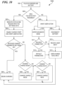
Fig. 10 , amethod 1000 illustrating operational steps of an embodiment of thebattery charger 100 is shown. AtStep 1001, the user may plug in thebattery charger 100 to a power source. Thebattery charger 100 may indicate that power is being received and that a battery may be connected by illuminating the Charge Rate /Progress indicators 120 in a "runway" pattern, followed by slow flashing of theCharge Status indicator 118. The user may connect the battery to be charged to thecharger output port 114. Additionally, the user may connect a balance port connector of the battery to be charged to the appropriatelysized balance port 116 ofbattery charger 100 if the battery to be charged is a LiPo type battery and is not implemented with an RFID tag. - At
Step 1002, thebattery charger 100 may determine if the battery connected to thecharger output port 114 is implemented with a readable RFID tag. If the battery inserted is implemented with an RFID tag that is readable by thesensor device 309 of thebattery charger 100, thebattery charger 100 may indicate to the user that a "smart" battery has been detected by illuminating thefirst switch 102, which may be the "Start / Stop" labeled push button, atStep 1003. Also atStep 1003, thebattery charger 100 may receive information from the RFID tag of the battery to be charged and configure the charging parameters of thebattery charger 100 in accordance with the information received from the battery to be charged and from default settings of thebattery charger 100. Illumination of the "Start / Stop" button may indicate to the user that thebattery charger 100 is ready to begin supplying a charge current to the battery and will do so upon the user pressing and holding the "Start / Stop" button for 2 seconds. - At
Step 1004, the battery charger may wait for user action. If thebattery charger 100 charging parameters are acceptable as configured, the user may begin charging operation by thebattery charger 100 by pressing and holding the "Start / Stop" button for 2 seconds atStep 1005. - If desired, the user may change the Charge Mode of the
battery charger 100 atStep 1006, by pressing the "Charge Mode" push button,switch 112, to toggle between available modes. During user selection of a Charge Mode atStep 1006, thebattery charger 100 may remain ready to begin supplying a charge current to the battery to be charged. The user may begin charging operation by thebattery charger 100 at any time by pressing and holding the "Start / Stop" button for 2 seconds. - Additionally, if desired, the user may change the Charge Rate of the
battery charger 100 atStep 1007, by simultaneously pressing and holding the "Start / Stop" and the "Charge Rate" push buttons, switches 102 and 104, respectively, for 2 seconds. This may place thebattery charger 100 in "Advanced Mode." The Charge Rate /Progress indicator 120 corresponding to the currently selected Charge Rate may begin flashing to indicate to the user that the battery charger is awaiting a Charge Rate selection by the user. The user may then change the Charge Rate to a desired setting by pressing the "Charge Rate" push button, thesecond switch 104, to toggle between available Charge Rates. During user selection of a Charge Rate atStep 1007, thebattery charger 100 may remain ready to begin supplying a charge current to the battery to be charged. The user may begin charging operation by thebattery charger 100 at any time by pressing and holding the "Start / Stop" button for 2 seconds. - Although the
method 1000, as shown inFig. 10 , orders the Charge Mode change step,Step 1006, before the Charge Rate change step,Step 1007, it should be noted that these steps may be performed in any order, relative to one another. For example, a user may elect to change the Charge Rate, first, before changing the Charge Mode. - Returning to Step 1002, if the
battery charger 100 determines that the connected battery is not implemented with an RFID tag, or is implemented with an unreadable RFID tag, thebattery charger 100 may indicate this status to the user atStep 1008. AtStep 1008, thebattery charger 100 may illuminate the Charging Rate /Status indicators 120 in a sweeping manner. Additionally, the "Start / Stop" push button may not illuminate. The battery charger may be configured to remain in this state and await action by the user. - The user may elect to disconnect and reconnect the battery, at
Step 1009, returning toStep 1001. The user may elect to take this action in instances where the battery connected is implemented with an RFID tag but an RFID connection was not made with thebattery charger 100 during coupling of the battery and thebattery charger 100. - Alternatively, the user may elect to enter "Advanced Mode" at
Step 1010, by simultaneously pressing and holding the "Start / Stop" and the "Charge Rate" push buttons, switches 102 and 104, respectively, for 2 seconds. The user may elect this action when the battery to be charged is not implemented with an RFID tag. - The
battery charger 100 may determine whether a balance port connector has been electrically coupled to abalance port 116 atStep 1011. If a balance connector is detected, thebattery charger 100 may select default charging parameter settings, such as setting the Battery Type to "LiPo" and setting the Charge Mode to "Balance" atStep 1012. - If no balance connector is detected, the
battery charger 100 may prompt the user to select a Battery Type by illuminating the BatteryType selection indicators 110 in an alternating manner atStep 1013. The user may select a Battery Type by pressing the "Battery Type" push button, theswitch 108, until the BatteryType selection indicator 110 corresponding to the desired Battery Type is illuminated. Thebattery charger 100 may select a default Charge Mode based on the Battery Type selected. For example, Balance mode may be selected for LiPo batteries and Fast mode selected for NiMH batteries. Additionally, thebattery charger 100 may be configured to indicate a Battery Type mismatch error if the user selects the "LiPo" Battery Type and thebattery charger 100 does not detect a balance connector coupled to abalance connector port 116, atStep 1013. - At
Step 1014, thebattery charger 100 may prompt the user to select a Charge Rate by illuminating the Charge Rate /Progress indicator 120A in a flashing mode. The user may select a Charge Rate by pressing the "Charge Rate" push button, theswitch 104, to toggle between available Charge Rates until the Charge Rate /Progress indicator 120 corresponding to the desired Charge Rate is illuminated. Once the user selects a Charge Rate, thebattery charger 100 may be configured to begin supplying a charge current to the battery to be charged. The user may begin charging operation by thebattery charger 100 by pressing and holding the "Start / Stop" button for 2 seconds. - Once charging commences, regardless of the Battery Type, Charge Mode, or Charge Rate selections, the
Charge Status indicator 118 may be configured to continuously "blink," indicating that a charging is in progress. The Charge Rate /Progress indicators 120 may also illuminate to display the amount of charge contained by the battery relative to the peak charge of the battery. Thebattery charger 100 may continuously monitor for undue delay in peak charge detection or over-temperature conditions using thermocouples, infrared radiation, and other methods. - The charge process may be halted by the occurrence of a peak charge detection timeout, or an over-temperature condition. Additionally, the charging may be halted by the user pressing the "Start / Stop" button or disconnecting the battery. If the "Start / Stop" button is pressed the
battery charger 100 may revert to its pre-charging configuration, with indicators illuminated to show current parameter setting selections. If the battery is disconnected during charging, thebattery charger 100 may be configured to illuminate the Charge Rate / Progress indicators in the "runway" pattern, indicating that thebattery charger 100 is awaiting coupling of a battery to thecharge output port 114. - Alternatively, if the charging process is not interrupted, and reaches completion, the
Charge Status indicator 118 may be configured to cease blinking and illuminate solidly. Further, the Charge Rate /Progress indicators 120 may turn off. Thebattery charger 100 may automatically begin "trickle charging" the battery for up to a pre-set amount of time while waiting for the user to disconnect the battery. - An embodiment of the
battery charger 200, as described above, may be implemented with a method of operation similar to that shown inFig. 10 and described in reference to thebattery charger 100, with the steps associated to LiPo battery charging omitted. - Having described the features and capabilities of several embodiments of a battery charger according to the present invention, along with a method of operation for the battery charger, several illustrative examples of battery charger use are now provided.
- The
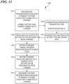
battery charger 100 may be used in accordance withmethod 1000 to balance charge a "smart" LiPo type battery implemented with an RFID chip using the RFID defined and default settings, as shown inFig. 11 . AtStep 1101, the battery charger may be electrically coupled to a power supply and the "smart" LiPo battery may be connected to the charge output port. The battery charger may then detect the RFID tag and respond by illuminating the "Start / Stop" button atStep 1102. The battery charger may then receive information from the battery RFID tag and may set the battery charger operating parameters to the "LiPo," "Balance," and "4A" settings atStep 1103. The user may then commence charging by pressing and holding the "Start / Stop" button for 2 seconds atStep 1104. - At
Step 1105, battery charging commences and theCharge Status indicator 118 "blinks." The Charge Rate /Progress indicators 120 also illuminate to display the amount of charge contained by the battery relative to the peak charge of the battery. - At
Step 1106, the charging process completes, theCharge Status indicator 118 may be configured to cease blinking and illuminate solidly. Further, the Charge Rate /Progress indicators 120 may turn off. Thebattery charger 100 may automatically begin "trickle charging" the battery for up to a pre-set amount of time while waiting for the user to disconnect the battery. Once the battery is disconnected, atStep 1107, thebattery charger 100 may illuminate the Charge Rate / Progress indicators in the "runway" pattern, indicating that thebattery charger 100 is awaiting coupling of a battery to thecharge output port 114. - The
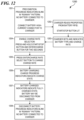
battery charger 100 may be used in accordance withmethod 1000 to balance charge a "smart" LiPo battery implemented with an RFID chip and using "Advanced Mode" to select the "2A" Charge Rate, as shown inFig. 12 . AtStep 1201, the battery charger may be electrically coupled to a power supply and the "smart" LiPo battery may be connected to the charge output port. The battery charger may then detect the RFID tag and respond by illuminating the "Start / Stop" button atStep 1202. The battery charger may then receive information from the battery RFID tag and may set the battery charger operating parameters to the "LiPo," "Balance," and "4A" settings atStep 1203. - At
Step 1204, the user may change the Charge Rate of thebattery charger 100 using "Advanced Mode" by simultaneously pressing and holding the "Start / Stop" and the "Charge Rate" push buttons for 2 seconds. The Charge Rate /Progress indicator 120 corresponding to the currently selected Charge Rate may begin flashing to indicate to the user that the battery charger is awaiting a Charge Rate selection by the user. - At
Step 1205, the user may change the Charge Rate to a desired setting of "2A" by pressing the "Charge Rate" push button twice. During user selection of a Charge Rate atStep 1205, thebattery charger 100 may remain ready to begin supplying a charge current to the battery to be charged. The user may begin charging operation atStep 1206 by pressing and holding the "Start / Stop" button for 2 seconds. - At
Step 1206, battery charging commences and theCharge Status indicator 118 "blinks." The Charge Rate /Progress indicators 120 also illuminate to display the amount of charge contained by the battery relative to the peak charge of the battery. AtStep 1207, the charging process completes, theCharge Status indicator 118 may be configured to cease blinking and illuminate solidly. Further, the Charge Rate /Progress indicators 120 may turn off. Thebattery charger 100 may automatically begin "trickle charging" the battery for up to a pre-set amount of time while waiting for the user to disconnect the battery. - Once the battery is disconnected, at
Step 1208, thebattery charger 100 may illuminate the Charge Rate / Progress indicators in the "runway" pattern, indicating that thebattery charger 100 is awaiting coupling of a battery to thecharge output port 114. - The
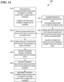
battery charger 100 may be used in accordance withmethod 1000 to charge a "smart" LiPo battery implemented with an RFID chip for storage, as shown inFig. 13 . AtStep 1301, the battery charger may be electrically coupled to a power supply and the "smart" LiPo battery may be connected to the charge output port. The battery charger may then detect the RFID tag and respond by illuminating the "Start / Stop" button atStep 1302. The battery charger may then receive information from the battery RFID tag and may set the battery charger operating parameters to the "LiPo," "Balance," and "4A" settings atStep 1303. - At
Step 1304, the user may change the Charge Mode of thebattery charger 100 by pressing the "Charge Mode," or "LIPO" push button until "Storage" mode is selected. During user selection of a Charge Mode atStep 1304, thebattery charger 100 may remain ready to begin supplying a charge current to the battery to be charged. The user may begin charging operation by pressing and holding the "Start / Stop" button for 2 seconds atstep 1305. - At
Step 1306, battery charging commences and theCharge Status indicator 118 "blinks." The Charge Rate /Progress indicators 120 also illuminate to display the amount of charge contained by the battery relative to the peak charge of the battery. AtStep 1307, the charging process completes, theCharge Status indicator 118 may be configured to cease blinking and illuminate solidly. Further, the Charge Rate /Progress indicators 120 may turn off. - Once the battery is disconnected, at
Step 1308, thebattery charger 100 may illuminate the Charge Rate / Progress indicators in the "runway" pattern, indicating that thebattery charger 100 is awaiting coupling of a battery to thecharge output port 114. - The
battery charger 100 may be used in accordance withmethod 1000 to balance charge a LiPo battery without an RFID chip, as shown inFig. 14 . AtStep 1401, the battery charger may be electrically coupled to a power supply and the LiPo battery may be connected to the charge output port. Additionally, a balance connector may be connected to a balance port of the battery charger atStep 1401. - At
Step 1402, the battery charger may detect that the battery is not implemented with an RFID tag and respond by illuminating the Charging Rate / Status indicators in a sweeping manner. The battery charger may remain in this state and await action by the user. AtStep 1403, the user may elect to enter "Advanced Mode" by simultaneously pressing and holding the "Start / Stop" and the "Charge Rate" push buttons for 2 seconds. - At
Step 1403, the battery charger may detect the balance connector electrically coupled to a balance port and may set the charging parameter settings to "LiPo" and "Balance." The "1A" Charge Rate / Progress indicator may begin flashing to indicate to the user that the battery charger is awaiting a Charge Rate selection by the user. - At
Step 1404, the user may change the Charge Rate to a desired setting of "4A" by pressing the "Charge Rate" push button three times. Upon user selection of a Charge Rate atStep 1404, thebattery charger 100 may become ready to begin supplying a charge current to the battery to be charged. The user may begin charging operation atStep 1405 by pressing and holding the "Start / Stop" button for 2 seconds. - At
Step 1406, battery charging commences and theCharge Status indicator 118 "blinks." The Charge Rate /Progress indicators 120 also illuminate to display the amount of charge contained by the battery relative to the peak charge of the battery. AtStep 1407, the charging process completes, theCharge Status indicator 118 may be configured to cease blinking and illuminate solidly. Further, the Charge Rate /Progress indicators 120 may turn off. Thebattery charger 100 may automatically begin "trickle charging" the battery for up to a pre-set amount of time while waiting for the user to disconnect the battery. - Once the battery is disconnected, at
Step 1408, thebattery charger 100 may illuminate the Charge Rate / Progress indicators in the "runway" pattern, indicating that thebattery charger 100 is awaiting coupling of a battery to thecharge output port 114. -
Fig. 15 illustrates how the battery charger may deter the user from charging a LiPo battery not implemented with an RFID tag without a balance connector coupled to a balance connector port. AtStep 1501, the battery charger may be electrically coupled to a power supply and the LiPo battery may be connected to the charge output port. - At
Step 1502, the battery charger may detect that the battery is not implemented with an RFID tag and respond by illuminating the Charging Rate / Status indicators in a sweeping manner. The battery charger may remain in this state and await action by the user. AtStep 1503, the user may elect to enter "Advanced Mode" by simultaneously pressing and holding the "Start / Stop" and the "Charge Rate" push buttons for 2 seconds. - At
Step 1504, the battery charger may detect that no balance connector is electrically coupled to a balance port and prompt the user to select a Battery Type by illuminating the LiPo and NiMH battery type selection indicators in an alternating manner. The user may select the "LiPo" Battery Type by pressing the "Battery Type" push button once at Step 1505. The battery charger may illuminate the "LiPo" Battery Type selection indicator in a solid mode and illuminate the Charge Mode selection indicator corresponding to "Balance." - At
Step 1506, the battery charger may detect that "LiPo" is selected while no balance connector is coupled to a balance connector port of the battery charger. The battery charger may indicate the error condition by illuminating the "1A" Charge Rate / Progress indicator in a blinking manner. The "1A" Charge Rate / Progress indicator may continue to blink until the user either disconnects the battery or presses the "Start / Stop" button. - The
battery charger 100 may be used in accordance withmethod 1000 to fully charge a "smart" NiMH type battery implemented with an RFID chip using the RFID defined and default settings, as shown inFig. 16 . AtStep 1601, the battery charger may be electrically coupled to a power supply and the "smart" NiMH battery may be connected to the charge output port. The battery charger may then detect the RFID tag and respond by illuminating the "Start / Stop" button atStep 1602. The battery charger may then receive information from the battery RFID tag and may set the battery charger operating parameters to the "NiMH" and "4A" settings atStep 1603. The user may then commence charging by pressing and holding the "Start / Stop" button for 2 seconds atStep 1604. - At
Step 1605, battery charging commences and theCharge Status indicator 118 "blinks." The Charge Rate /Progress indicators 120 also illuminate to display the amount of charge contained by the battery relative to the peak charge of the battery. - At
Step 1606, the charging process completes, theCharge Status indicator 118 may be configured to cease blinking and illuminate solidly. Further, the Charge Rate /Progress indicators 120 may turn off. Thebattery charger 100 may automatically begin "trickle charging" the battery for up to a pre-set amount of time while waiting for the user to disconnect the battery. Once the battery is disconnected, atStep 1607, thebattery charger 100 may, inStep 1608, illuminate the Charge Rate / Progress indicators in the "runway" pattern, indicating that thebattery charger 100 is awaiting coupling of a battery to thecharge output port 114. - The
battery charger 100 may be used in accordance withmethod 1000 to fully charge a NiMH battery without an RFID chip, as shown inFig. 17 . AtStep 1701, the battery charger may be electrically coupled to a power supply and the NiMH battery may be connected to the charge output port. - At
Step 1702, the battery charger may detect that the battery is not implemented with an RFID tag and respond by illuminating the Charging Rate / Status indicators in a sweeping manner. The battery charger may remain in this state and await action by the user. AtStep 1703, the user may elect to enter "Advanced Mode" by simultaneously pressing and holding the "Start / Stop" and the "Charge Rate" push buttons for 2 seconds. - At
Step 1704, the battery charger may detect that no balance connector is electrically coupled to a balance port and prompt the user to select a Battery Type by illuminating the "LiPo" and "NiMH" battery type selection indicators in an alternating manner. The user may select the "NiMH" Battery Type by pressing the "Battery Type" push button twice atStep 1705. The battery charger may illuminate the "NiMH" Battery Type selection indicator in a solid mode. - At
Step 1706, the "1A" Charge Rate / Progress indicator may begin flashing to indicate to the user that the battery charger is awaiting a Charge Rate selection by the user. AtStep 1707, the user may change the Charge Rate to a desired setting of "4A" by pressing the "Charge Rate" push button three times. Upon user selection of a Charge Rate, thebattery charger 100 may become ready to begin supplying a charge current to the battery to be charged. The user may begin charging operation atStep 1708 by pressing and holding the "Start / Stop" button for 2 seconds. - At
Step 1709, battery charging commences and theCharge Status indicator 118 "blinks." The Charge Rate /Progress indicators 120 also illuminate to display the amount of charge contained by the battery relative to the peak charge of the battery. AtStep 1710, the charging process completes, theCharge Status indicator 118 may be configured to cease blinking and illuminate solidly. Further, the Charge Rate /Progress indicators 120 may turn off. Thebattery charger 100 may automatically begin "trickle charging" the battery for up to a pre-set amount of time while waiting for the user to disconnect the battery. - Once the battery is disconnected, at
Step 1711, thebattery charger 100 may illuminate the Charge Rate / Progress indicators in the "runway" pattern, indicating that thebattery charger 100 is awaiting coupling of a battery to thecharge output port 114. - It should be appreciated that an embodiment of the
battery charger 200, as described above, may be implemented with a method of operation similar to that shown inFig. 10 and described in reference to thebattery charger 100, with the steps associated to LiPo battery charging omitted, to perform the charging operations described inFigs. 16 and17 above.
Claims (14)
- A battery charger (100), comprising:an electrical connector (2100) for electrically coupling to a battery (150) and delivering a configurable electrical charge for charging a battery (150);a sensor device (309) for receiving information from a battery (150) to be charged, the sensor device (309) positioned to receive the information from an RFID tag (206) connected to a battery (150) to be charged when the battery (150) is electrically coupled to the electrical connector (2100);a memory (316) for storing a plurality of predefined charging parameter settings, with the predefined charging parameter settings configured to correspond to information receivable from a battery (150) to be charged; andone or more balance connector ports (116A, 116B) for receiving a balance connector of a lithium-polymer type battery (150);wherein the battery charger (100) at least partially configures the electrical charge delivered in accordance with predefined charging parameter settings corresponding to information received from a battery (150) to be charged, the charging parameter settings comprise at least a charge mode setting, the charge mode setting comprising at least a balance charge setting;wherein the battery charger (100) is configured to be compatible with at least lithium-polymer batteries;wherein the battery charger (100) is further configured to determine whether the battery (150) connected to the charger output port (114) is implemented with a readable RFID tag (206);wherein the battery charger (100) is further configured to configure, upon determining that the battery connected to the charger output port (114) is implemented with a readable RFID tag (206), the charging parameter settings in accordance with the information received from the battery (150) to be charged;characterized in that the battery charger (100) is further configured to determine, upon determining that the battery (150) connected to the charger output port (114) is not implemented with a readable RFID tag (206) or implemented with an unreadable RFID tag (206), whether a balance connector has been electrically coupled to the balance connector port (116A, 116B), and to select, upon determining the balance connector has been electrically coupled to the balance connector port (116A, 116B), the charge mode setting to the balance charge setting.
- The battery charger of Claim 1, further comprising a battery information receipt indicator, wherein the battery information receipt indicator comprises a light emitting device configured to illuminate upon receipt of information from a battery (150) to be charged.
- The battery charger of Claim 1, further comprising a first switch, wherein the first switch (102) comprises a first button for initiating delivery of a charge to a battery (150) to be charged when the first button is depressed following the sensor device (309) receiving information from the battery (150) to be charged.
- The battery charger of Claim 3, configured such that depressing the first button while the battery charger (100) is delivering an electrical charge to a battery (150) terminates delivery of the electrical charge.
- The battery charger of Claim 1, further comprising a charge progress indicator (120), wherein the charge progress indicator (120) comprises a plurality of light emitting devices configured to illuminate in succession for indicating the amount of electrical charge delivered to a battery (150) to be charged.
- The battery charger of Claim 5, configured such that the plurality of light emitting devices illuminate in a first mode when the electrical connector is coupled to a battery (150) to be charged and information is received by the sensor device (309) from the battery (150) to be charged, and in a second mode when the electrical connector is coupled to a battery (150) to be charged and no information is received by the sensor device (309) from the battery (150) to be charged.
- The battery charger of Claim 1, further comprising a charge rate indicator (120), wherein the charge rate indicator (120) comprises a plurality of light emitting devices configured to illuminate in succession for indicating the amperage of the electrical charge delivered to a battery (150) to be charged, when a battery (150) to be charged is coupled to the battery charger (100) and when the battery charger (100) is not delivering an electrical charge for charging the battery (150).
- The battery charger of Claim 1, wherein the battery charger (100) is configured to be further compatible with nickel-metal hydride batteries, and wherein the charging parameter settings further comprise a charge rate setting and a battery type setting.
- The battery charger of Claim 8, wherein the battery charger (100, 200) is further configured to automatically select the battery type charge parameter setting corresponding to lithium-polymer batteries, upon determining the balance connector has been electrically coupled to the balance port (116A, 116B).
- The battery charger of Claim 8, wherein the charge mode parameter setting further comprises a storage charge setting and a fast charge setting.
- The battery charger of Claim 8, further comprising:a first switch (102), wherein the first switch (102) comprises a first button for initiating delivery of a charge to a battery (150) to be charged when the first button is depressed;a second switch (104) comprising a charge rate selection button, wherein depressing the charge rate selection button varies the charge rate setting in relation to the number of times the second button is depressed; anda third switch (108) comprising a battery type selection button, wherein depressing the battery type selection button toggles the battery type parameter setting between at least two settings.
- The battery charger of Claim 11, further comprising:
a fourth switch (112), wherein the fourth switch (112) comprises a charge mode selection button, wherein depressing the charge mode selection toggles the charge mode parameter setting between at least three charge mode parameter settings when the battery (150) to be charged is a lithium-polymer type battery. - The battery charger of Claim 1, wherein
the user may configure the charge delivered by manually adjusting one or more of the charging parameter settings, whereby the user may alter the one or more charging parameter settings from the predefined charging parameter settings corresponding to information receivable from a battery (150) to be charged, wherein the battery charger (100) further comprises:a switch (104) comprising a charge rate selection button;wherein the charging parameter settings comprise at least a charge rate setting; andwherein depressing the charge rate selection button varies the charge rate setting in relation to the number of times the charge rate selection button is depressed. - A method of configuring the charge delivered by a battery charger (100), which is configured to be compatible with at least lithium-polymer batteries and comprises one or more balance connector ports (116A, 116B) for receiving a balance connector of a lithium-polymer type battery (150);
the method comprising:- electrically coupling the battery charger (100) to a battery (150) to be charged, therein connecting the battery to be charged to a charger output port (114);- determining, whether the battery (150) connected to the charger output port (114) is implemented with a readable RFID tag (206);- upon determining that the battery connected to the charger output port (114) is implemented with a readable RFID tag (206):(i) receiving information from the RFID tag (206);(ii) configuring charging parameter settings of the battery charger (100) in accordance with the information received from the battery (150) to be charged, the charging parameter settings comprising at least a charge mode setting, the charge mode setting comprising at least a balance charge setting;- upon determining that the battery connected to the charger output port (114) is not implemented with a readable RFID tag (206):(i) determining, whether a balance connector has been electrically coupled to the balance connector port (116A, 116B) of the battery charger;(ii) selecting, upon determining the balance connector has been electrically coupled to the balance connector port (116A, 116B), the charge mode setting to the balance charge setting;- initiating delivery of the configured charge in response to depression of a first button by a user.
Applications Claiming Priority (2)
| Application Number | Priority Date | Filing Date | Title |
|---|---|---|---|
| US14/504,398 US10396568B2 (en) | 2014-06-03 | 2014-10-01 | Battery charger with user interface |
| PCT/US2015/053466 WO2016054359A1 (en) | 2014-10-01 | 2015-10-01 | Battery charger with user interface |
Publications (2)
| Publication Number | Publication Date |
|---|---|
| EP3202012A1 EP3202012A1 (en) | 2017-08-09 |
| EP3202012B1 true EP3202012B1 (en) | 2023-11-15 |
Family
ID=54347828
Family Applications (1)
| Application Number | Title | Priority Date | Filing Date |
|---|---|---|---|
| EP15784818.5A Active EP3202012B1 (en) | 2014-10-01 | 2015-10-01 | Battery charger with user interface |
Country Status (4)
| Country | Link |
|---|---|
| US (1) | US10396568B2 (en) |
| EP (1) | EP3202012B1 (en) |
| CN (1) | CN106797129B (en) |
| WO (1) | WO2016054359A1 (en) |
Families Citing this family (9)
| Publication number | Priority date | Publication date | Assignee | Title |
|---|---|---|---|---|
| DE112015002653B4 (en) | 2014-06-03 | 2025-02-06 | Traxxas Lp | Female and male electrical connector and associated battery and associated electrically operated device |
| US20160226278A1 (en) * | 2015-02-02 | 2016-08-04 | Black & Decker Inc. | Power tool battery pack and system |
| US10333322B2 (en) * | 2015-03-24 | 2019-06-25 | Horizon Hobby, LLC | Systems and methods for battery charger with safety component |
| US10663529B1 (en) * | 2015-09-25 | 2020-05-26 | Amazon Technologies, Inc. | Automatic battery charging |
| DE102018210524A1 (en) | 2018-06-27 | 2020-01-02 | Robert Bosch Gmbh | Process for charging battery packs for power tools and charger for carrying out the process |
| US11460907B2 (en) * | 2019-10-08 | 2022-10-04 | Eaton Intelligent Power Limited | Receptacle with an integrated power meter |
| US20240022097A1 (en) * | 2020-12-18 | 2024-01-18 | Milwaukee Electric Tool Corporation | Multi-bay battery charger |
| CN117223188A (en) * | 2021-04-27 | 2023-12-12 | 米沃奇电动工具公司 | Includes battery pack charger with programmable power levels |
| GB202217380D0 (en) | 2022-11-21 | 2023-01-04 | Nyobolt Ltd | Charging and discharging system |
Citations (2)
| Publication number | Priority date | Publication date | Assignee | Title |
|---|---|---|---|---|
| US7888913B1 (en) * | 2009-09-08 | 2011-02-15 | Intermec Ip Corp. | Smart battery charger |
| US20120249083A1 (en) * | 2011-03-29 | 2012-10-04 | Eddie Garrastacho | Method and device for voltage detection and charging of electric battery |
Family Cites Families (94)
| Publication number | Priority date | Publication date | Assignee | Title |
|---|---|---|---|---|
| US3794957A (en) | 1973-01-22 | 1974-02-26 | Anderson Power Products | Plural-poled, genderless electrical connector |
| US4193655A (en) | 1978-07-20 | 1980-03-18 | Amp Incorporated | Field repairable connector assembly |
| US5049804A (en) | 1987-06-01 | 1991-09-17 | Power-Tech Systems Corporation | Universal battery charging system and a method |
| JPH0340728A (en) | 1989-07-05 | 1991-02-21 | Nec Corp | Portable radio telephone charger |
| US5111128A (en) | 1990-12-17 | 1992-05-05 | Motorola, Inc. | Battery identification apparatus |
| US5535274A (en) | 1991-10-19 | 1996-07-09 | Cellport Labs, Inc. | Universal connection for cellular telephone interface |
| US5283512A (en) | 1992-04-13 | 1994-02-01 | Hughes Aircraft Company | Charge balancing of batteries during charging |
| US5592069A (en) | 1992-10-07 | 1997-01-07 | Dallas Semiconductor Corporation | Battery charger |
| US5371453A (en) | 1993-01-28 | 1994-12-06 | Motorola, Inc. | Battery charger system with common charge and data exchange port |
| US5370556A (en) | 1993-09-20 | 1994-12-06 | The Whitaker Corporation | Keying system for electrical connectors |
| US5575674A (en) | 1994-07-29 | 1996-11-19 | The Whitaker Corporation | Connector adapted for hermaphroditic construction |
| KR970024434A (en) | 1995-10-12 | 1997-05-30 | 김광호 | Combined Battery Charger and Control Method |
| IL116345A0 (en) | 1995-12-12 | 1996-03-31 | Electric Fuel Ltd | A battery connector for use with an electric vehicle and a metal-air battery |
| US5881454A (en) | 1996-11-25 | 1999-03-16 | Seagate Technology, Inc. | Method of making single-sided electronic connector |
| US5865651A (en) | 1996-12-17 | 1999-02-02 | Seagate Technology, Inc. | Female connector for mating with 3-in-1 IDE interface and power connector with recesses and projections for facilitating engagement |
| US5844400A (en) | 1997-02-20 | 1998-12-01 | Telxon Corporation | Battery discriminating system for charging a battery of a mobile terminal |
| AU8374698A (en) | 1997-06-27 | 1999-01-19 | Patrick H. Potega | Apparatus for monitoring temperature of a power source |
| US7059769B1 (en) | 1997-06-27 | 2006-06-13 | Patrick Henry Potega | Apparatus for enabling multiple modes of operation among a plurality of devices |
| US6634896B1 (en) | 1997-06-27 | 2003-10-21 | Patrick Potega | Method and apparatus for transferring electrical signals among electrical devices |
| US5949216A (en) | 1997-08-27 | 1999-09-07 | Ericsson Inc. | Dual mode battery chargers for portable electronic devices and related methods |
| US6007362A (en) | 1997-12-09 | 1999-12-28 | The Whitaker Corporation | Electrical connector assembly for a refrigerator door |
| US6014008A (en) | 1998-01-22 | 2000-01-11 | Ericsson, Inc. | Battery identification system |
| US6022246A (en) | 1998-05-08 | 2000-02-08 | Hon Hai Precision Ind. Co., Ltd. | Arrangement for preventing mis-mating of connector assembly |
| DE69931886T2 (en) | 1998-09-11 | 2006-11-16 | Hosiden Corp., Yao | CONNECTION BOX, CONNECTOR PLUG AND CONNECTION ASSEMBLY |
| US6232750B1 (en) * | 1999-06-08 | 2001-05-15 | Enrey Corporation | Battery charger with enhanced charging and charge measurement processes |
| SE9902778L (en) | 1999-07-23 | 2001-01-24 | Uma Trading Ab | Connection pre-connection of a battery to a charging unit |
| US6184655B1 (en) | 1999-12-10 | 2001-02-06 | Stryker Corporation | Battery charging system with internal power manager |
| US6236186B1 (en) | 1999-12-23 | 2001-05-22 | Intermec Ip | Method and system for discriminating between different types of batteries and charging the same |
| EP1128517A3 (en) | 2000-02-24 | 2003-12-10 | Makita Corporation | Adapters for rechargeable battery packs |
| JP2002320341A (en) | 2001-02-14 | 2002-10-31 | Sony Corp | Charge / discharge device and method, power supply device and method, power supply system and method, program storage medium, and program |
| JP2003259560A (en) | 2002-02-28 | 2003-09-12 | Mitsumi Electric Co Ltd | Charging circuit |
| KR100493080B1 (en) | 2002-10-05 | 2005-06-02 | 삼성전자주식회사 | Device for charging battery of portable communication terminal |
| USD494933S1 (en) | 2002-12-19 | 2004-08-24 | K.S. Terminals Inc. | Electricity connector |
| AU2003900633A0 (en) | 2003-02-13 | 2003-02-27 | Energy Storage Systems Pty Ltd | A resistive balance for an energy storage device |
| US6746284B1 (en) | 2003-10-02 | 2004-06-08 | Hon Hai Precision Ind. Co., Ltd. | Electrical connector assembly having signal and power terminals |
| US7271568B2 (en) * | 2004-02-11 | 2007-09-18 | Research In Motion Limited | Battery charger for portable devices and related methods |
| JP2005237155A (en) | 2004-02-20 | 2005-09-02 | Macnica Inc | Battery charger applicable to multiple-voltage specifications, battery charging system, and battery unit |
| US20050248310A1 (en) | 2004-05-07 | 2005-11-10 | Diversified Power International Llc | Multi-type battery charger control |
| JP4345594B2 (en) | 2004-07-02 | 2009-10-14 | 住友電装株式会社 | connector |
| DE202004012366U1 (en) | 2004-08-06 | 2004-10-21 | Robbe Modellsport Gmbh & Co. Kg | Device for identifying electrically chargeable/dischargeable battery pack parameters e.g. for model construction vehicles, has battery pack coupled to non-volatile information-storage module coupled to information reading device in charger |
| US20060145661A1 (en) | 2004-12-30 | 2006-07-06 | Joseph Patino | System and method for operating a multiple charger |
| KR200398706Y1 (en) | 2005-08-04 | 2005-10-14 | 남상률 | Battery charger for portable equipment |
| JP4155408B2 (en) | 2005-09-29 | 2008-09-24 | ソニー・エリクソン・モバイルコミュニケーションズ株式会社 | Charging device and charging system |
| JP4420879B2 (en) | 2005-09-29 | 2010-02-24 | 三洋電機株式会社 | Charger |
| USD577671S1 (en) | 2005-11-21 | 2008-09-30 | Erbe Elektromedizin Gmbh | Connector |
| US7952322B2 (en) * | 2006-01-31 | 2011-05-31 | Mojo Mobility, Inc. | Inductive power source and charging system |
| US7554292B2 (en) | 2006-06-21 | 2009-06-30 | Research In Motion Limited | Battery charger for simultaneously charging a plurality of batteries |
| TWI426678B (en) | 2006-06-28 | 2014-02-11 | 波士頓電力公司 | Electronic device with multiple charging rate, battery pack, method for charging lithium ion charge storage power supply in electronic device and portable computer |
| USD552560S1 (en) | 2006-08-28 | 2007-10-09 | Jay Victor | Breakout for cable assembly |
| JP4755056B2 (en) | 2006-09-15 | 2011-08-24 | 日本圧着端子製造株式会社 | connector |
| USD573536S1 (en) | 2007-04-17 | 2008-07-22 | Traxxas Lp | Electrical connector |
| US7374460B1 (en) | 2007-04-17 | 2008-05-20 | Traxxas Lp | Electrical connector assembly |
| USD576557S1 (en) | 2007-04-17 | 2008-09-09 | Traxxas Lp | Electrical connector |
| USD589881S1 (en) | 2007-05-10 | 2009-04-07 | Molex Incorporated | Projector lamp connector |
| US7808205B2 (en) | 2007-05-29 | 2010-10-05 | Motorola, Inc | Battery charger and method for communicating battery pack charging status information |
| JP5074490B2 (en) | 2007-06-13 | 2012-11-14 | 京セラ株式会社 | Charging system, portable electronic device, battery terminal used therefor, and secondary battery |
| US8035343B2 (en) | 2007-10-15 | 2011-10-11 | Black & Decker Inc. | Method for balancing cells in a battery pack |
| JP5050823B2 (en) | 2007-12-10 | 2012-10-17 | 住友電装株式会社 | connector |
| CN201210314Y (en) | 2008-05-15 | 2009-03-18 | 上海燃料电池汽车动力系统有限公司 | Electric automobile charging device having identity recognition function |
| US7880434B2 (en) | 2008-05-21 | 2011-02-01 | Southwest Electronic Energy Corporation | System for balancing a plurality of battery pack system modules connected in series |
| MX2011002544A (en) | 2008-09-08 | 2011-05-25 | Techtronic Power Tools Tech | BATTERY CHARGER. |
| DE102008049574A1 (en) | 2008-09-30 | 2010-04-01 | Phoenix Contact Gmbh & Co. Kg | Electrical connector system |
| US9762069B2 (en) | 2009-05-19 | 2017-09-12 | Duracell U.S. Operations, Inc. | Multi-use fast rate charging stand |
| US8483850B2 (en) | 2009-05-21 | 2013-07-09 | Lennox Industries Inc. | HVAC system, a method for determining a location of an HVAC unit with respect to a site and an HVAC controller |
| US8491341B2 (en) | 2009-07-01 | 2013-07-23 | Vertical Partners West, Llc | Universal battery connector |
| US9722334B2 (en) * | 2010-04-07 | 2017-08-01 | Black & Decker Inc. | Power tool with light unit |
| US8179092B2 (en) | 2010-04-12 | 2012-05-15 | Concorde Battery Corporation | Lithium-ion aircraft battery with automatically activated battery management system |
| JP2011243426A (en) | 2010-05-18 | 2011-12-01 | Sanyo Electric Co Ltd | Battery pack and battery pack connector |
| USD659640S1 (en) | 2010-07-23 | 2012-05-15 | Heavy Power Co. Ltd. | Luminaire disconnect |
| JP5573471B2 (en) | 2010-08-05 | 2014-08-20 | スズキ株式会社 | Battery pack |
| JP5464106B2 (en) | 2010-09-08 | 2014-04-09 | 住友電装株式会社 | connector |
| ES2836195T3 (en) | 2010-10-27 | 2021-06-24 | The Aes Corp | Procedures for use with electrical equipment to manage energy services |
| USD665748S1 (en) | 2010-10-28 | 2012-08-21 | Anderson Power Products | Finger proof, keyed power connector |
| US9190855B2 (en) | 2011-06-17 | 2015-11-17 | Southwest Electronic Energy Corporation | Module bypass switch with bypass current monitoring |
| USD662889S1 (en) | 2011-08-03 | 2012-07-03 | Anderson Power Products, Inc. | Polarized 3 pole electrical connector with protective ground |
| JP2013051780A (en) | 2011-08-30 | 2013-03-14 | Toyota Industries Corp | Charging system for vehicle and charging cable for vehicle |
| CN103931076A (en) | 2011-09-02 | 2014-07-16 | 波士顿电力公司 | Method for balancing cells in a battery |
| JP5790434B2 (en) | 2011-11-18 | 2015-10-07 | ソニー株式会社 | Electronic device, charging control method, charging system, and data transfer system |
| DE202012000291U1 (en) * | 2012-01-13 | 2012-02-15 | Cei Conrad Electronic International (Hk) Ltd. | loader |
| JP5884135B2 (en) | 2012-01-25 | 2016-03-15 | 矢崎総業株式会社 | Connector unit |
| US20130260182A1 (en) | 2012-03-27 | 2013-10-03 | Caterpillar, Inc. | PCB with Both High and Low Current Traces for Energy Storage Modules |
| JP5803798B2 (en) | 2012-04-26 | 2015-11-04 | 住友電装株式会社 | Terminal fitting |
| KR102044758B1 (en) | 2012-09-05 | 2019-11-15 | 르네사스 일렉트로닉스 가부시키가이샤 | Non-contact charging device, and non-contact power supply system using same |
| DE202012103996U1 (en) | 2012-10-18 | 2013-01-09 | Eckhard Schitter | Charging cable and charging system for electric vehicles |
| US9059590B2 (en) * | 2013-02-26 | 2015-06-16 | Bby Solutions, Inc. | Universal battery charger system and method |
| CA2908155A1 (en) | 2013-04-11 | 2014-10-16 | Sony Corporation | Battery apparatus |
| DE202013004312U1 (en) | 2013-05-10 | 2013-08-12 | Heinrich Kohorst | Housing for receiving plugs and cables, which are used for connecting devices for the identification of parameters electrically charged and rechargeable storage and charger devices. |
| TWM474284U (en) | 2013-11-05 | 2014-03-11 | Bellwether Electronic Corp | Power connector plug and power connector socket |
| CN104733911B (en) | 2013-12-23 | 2017-03-15 | 凡甲电子(苏州)有限公司 | Electric connector combination |
| CN203721910U (en) | 2014-03-06 | 2014-07-16 | 泰科电子(上海)有限公司 | An electric connector used for connecting wires |
| DE112015002653B4 (en) | 2014-06-03 | 2025-02-06 | Traxxas Lp | Female and male electrical connector and associated battery and associated electrically operated device |
| CN104037920B (en) * | 2014-06-24 | 2016-03-23 | 杭州电子科技大学 | A lead-acid battery intelligent charging control system |
| USD743339S1 (en) | 2014-07-22 | 2015-11-17 | Traxxas Lp | Female electrical connector |
| USD743338S1 (en) | 2014-07-22 | 2015-11-17 | Traxxas Lp | Male electrical connector |
-
2014
- 2014-10-01 US US14/504,398 patent/US10396568B2/en active Active
-
2015
- 2015-10-01 WO PCT/US2015/053466 patent/WO2016054359A1/en not_active Ceased
- 2015-10-01 CN CN201580054089.2A patent/CN106797129B/en active Active
- 2015-10-01 EP EP15784818.5A patent/EP3202012B1/en active Active
Patent Citations (2)
| Publication number | Priority date | Publication date | Assignee | Title |
|---|---|---|---|---|
| US7888913B1 (en) * | 2009-09-08 | 2011-02-15 | Intermec Ip Corp. | Smart battery charger |
| US20120249083A1 (en) * | 2011-03-29 | 2012-10-04 | Eddie Garrastacho | Method and device for voltage detection and charging of electric battery |
Also Published As
| Publication number | Publication date |
|---|---|
| CN106797129B (en) | 2020-10-27 |
| EP3202012A1 (en) | 2017-08-09 |
| US10396568B2 (en) | 2019-08-27 |
| CN106797129A (en) | 2017-05-31 |
| US20160099580A1 (en) | 2016-04-07 |
| WO2016054359A1 (en) | 2016-04-07 |
Similar Documents
| Publication | Publication Date | Title |
|---|---|---|
| EP3202011B1 (en) | Battery charger with user interface | |
| EP3202012B1 (en) | Battery charger with user interface | |
| US20250389247A1 (en) | Multifunctional Battery Booster | |
| JP7198293B2 (en) | battery charger | |
| US10326292B2 (en) | Battery charger operating method and method usable with plural different power supplies | |
| US7525280B2 (en) | Multi-type battery charger control | |
| US8598850B2 (en) | Devices and methods for optimizing rechargeable battery life | |
| CN102738845A (en) | Improved Series Independent Detection Battery Charger | |
| CN109891704B (en) | Equipment for jump-starting a vehicle | |
| JP2008259293A (en) | Secondary battery charger | |
| KR20180006686A (en) | a compatible adapter for the batterty of the electrically drive tool | |
| EP2561593A2 (en) | Built-in charger | |
| CN217283323U (en) | Charging bin circuit, charging bin and earphone equipment | |
| CN112531848B (en) | A battery pack and its control method | |
| CN109004708B (en) | Charging equipment and mobile terminal | |
| CN216056400U (en) | A battery charging device that can be automatically identified | |
| JP6189417B2 (en) | Power supply device and method for supplying power to electronic equipment connected to the power supply device | |
| KR20210018037A (en) | Free volt type charging device using all-round charging cable | |
| CN221531008U (en) | USB-powered V-port battery charger | |
| KR200253486Y1 (en) | Variety Multiple Use Battery Charging Set | |
| US20240339855A1 (en) | Method for rapid charging of a rechargeable battery | |
| WO2016145194A1 (en) | Battery charger usable with plural different power supplies and usb connector usable therewith and otherwise | |
| JP2024171993A (en) | Charger |
Legal Events
| Date | Code | Title | Description |
|---|---|---|---|
| STAA | Information on the status of an ep patent application or granted ep patent |
Free format text: STATUS: THE INTERNATIONAL PUBLICATION HAS BEEN MADE |
|
| PUAI | Public reference made under article 153(3) epc to a published international application that has entered the european phase |
Free format text: ORIGINAL CODE: 0009012 |
|
| STAA | Information on the status of an ep patent application or granted ep patent |
Free format text: STATUS: REQUEST FOR EXAMINATION WAS MADE |
|
| 17P | Request for examination filed |
Effective date: 20170405 |
|
| AK | Designated contracting states |
Kind code of ref document: A1 Designated state(s): AL AT BE BG CH CY CZ DE DK EE ES FI FR GB GR HR HU IE IS IT LI LT LU LV MC MK MT NL NO PL PT RO RS SE SI SK SM TR |
|
| AX | Request for extension of the european patent |
Extension state: BA ME |
|
| DAV | Request for validation of the european patent (deleted) | ||
| DAX | Request for extension of the european patent (deleted) | ||
| STAA | Information on the status of an ep patent application or granted ep patent |
Free format text: STATUS: EXAMINATION IS IN PROGRESS |
|
| 17Q | First examination report despatched |
Effective date: 20180215 |
|
| GRAP | Despatch of communication of intention to grant a patent |
Free format text: ORIGINAL CODE: EPIDOSNIGR1 |
|
| STAA | Information on the status of an ep patent application or granted ep patent |
Free format text: STATUS: GRANT OF PATENT IS INTENDED |
|
| INTG | Intention to grant announced |
Effective date: 20230609 |
|
| GRAS | Grant fee paid |
Free format text: ORIGINAL CODE: EPIDOSNIGR3 |
|
| GRAA | (expected) grant |
Free format text: ORIGINAL CODE: 0009210 |
|
| STAA | Information on the status of an ep patent application or granted ep patent |
Free format text: STATUS: THE PATENT HAS BEEN GRANTED |
|
| AK | Designated contracting states |
Kind code of ref document: B1 Designated state(s): AL AT BE BG CH CY CZ DE DK EE ES FI FR GB GR HR HU IE IS IT LI LT LU LV MC MK MT NL NO PL PT RO RS SE SI SK SM TR |
|
| REG | Reference to a national code |
Ref country code: CH Ref legal event code: EP Ref country code: GB Ref legal event code: FG4D |
|
| REG | Reference to a national code |
Ref country code: DE Ref legal event code: R096 Ref document number: 602015086551 Country of ref document: DE |
|
| REG | Reference to a national code |
Ref country code: IE Ref legal event code: FG4D |
|
| REG | Reference to a national code |
Ref country code: LT Ref legal event code: MG9D |
|
| REG | Reference to a national code |
Ref country code: NL Ref legal event code: MP Effective date: 20231115 |
|
| PG25 | Lapsed in a contracting state [announced via postgrant information from national office to epo] |
Ref country code: GR Free format text: LAPSE BECAUSE OF FAILURE TO SUBMIT A TRANSLATION OF THE DESCRIPTION OR TO PAY THE FEE WITHIN THE PRESCRIBED TIME-LIMIT Effective date: 20240216 |
|
| PG25 | Lapsed in a contracting state [announced via postgrant information from national office to epo] |
Ref country code: IS Free format text: LAPSE BECAUSE OF FAILURE TO SUBMIT A TRANSLATION OF THE DESCRIPTION OR TO PAY THE FEE WITHIN THE PRESCRIBED TIME-LIMIT Effective date: 20240315 |
|
| PG25 | Lapsed in a contracting state [announced via postgrant information from national office to epo] |
Ref country code: LT Free format text: LAPSE BECAUSE OF FAILURE TO SUBMIT A TRANSLATION OF THE DESCRIPTION OR TO PAY THE FEE WITHIN THE PRESCRIBED TIME-LIMIT Effective date: 20231115 |
|
| REG | Reference to a national code |
Ref country code: AT Ref legal event code: MK05 Ref document number: 1632662 Country of ref document: AT Kind code of ref document: T Effective date: 20231115 |
|
| PG25 | Lapsed in a contracting state [announced via postgrant information from national office to epo] |
Ref country code: NL Free format text: LAPSE BECAUSE OF FAILURE TO SUBMIT A TRANSLATION OF THE DESCRIPTION OR TO PAY THE FEE WITHIN THE PRESCRIBED TIME-LIMIT Effective date: 20231115 |
|
| PG25 | Lapsed in a contracting state [announced via postgrant information from national office to epo] |
Ref country code: AT Free format text: LAPSE BECAUSE OF FAILURE TO SUBMIT A TRANSLATION OF THE DESCRIPTION OR TO PAY THE FEE WITHIN THE PRESCRIBED TIME-LIMIT Effective date: 20231115 |
|
| PG25 | Lapsed in a contracting state [announced via postgrant information from national office to epo] |
Ref country code: ES Free format text: LAPSE BECAUSE OF FAILURE TO SUBMIT A TRANSLATION OF THE DESCRIPTION OR TO PAY THE FEE WITHIN THE PRESCRIBED TIME-LIMIT Effective date: 20231115 |
|
| PG25 | Lapsed in a contracting state [announced via postgrant information from national office to epo] |
Ref country code: NL Free format text: LAPSE BECAUSE OF FAILURE TO SUBMIT A TRANSLATION OF THE DESCRIPTION OR TO PAY THE FEE WITHIN THE PRESCRIBED TIME-LIMIT Effective date: 20231115 Ref country code: LT Free format text: LAPSE BECAUSE OF FAILURE TO SUBMIT A TRANSLATION OF THE DESCRIPTION OR TO PAY THE FEE WITHIN THE PRESCRIBED TIME-LIMIT Effective date: 20231115 Ref country code: IS Free format text: LAPSE BECAUSE OF FAILURE TO SUBMIT A TRANSLATION OF THE DESCRIPTION OR TO PAY THE FEE WITHIN THE PRESCRIBED TIME-LIMIT Effective date: 20240315 Ref country code: GR Free format text: LAPSE BECAUSE OF FAILURE TO SUBMIT A TRANSLATION OF THE DESCRIPTION OR TO PAY THE FEE WITHIN THE PRESCRIBED TIME-LIMIT Effective date: 20240216 Ref country code: ES Free format text: LAPSE BECAUSE OF FAILURE TO SUBMIT A TRANSLATION OF THE DESCRIPTION OR TO PAY THE FEE WITHIN THE PRESCRIBED TIME-LIMIT Effective date: 20231115 Ref country code: BG Free format text: LAPSE BECAUSE OF FAILURE TO SUBMIT A TRANSLATION OF THE DESCRIPTION OR TO PAY THE FEE WITHIN THE PRESCRIBED TIME-LIMIT Effective date: 20240215 Ref country code: AT Free format text: LAPSE BECAUSE OF FAILURE TO SUBMIT A TRANSLATION OF THE DESCRIPTION OR TO PAY THE FEE WITHIN THE PRESCRIBED TIME-LIMIT Effective date: 20231115 Ref country code: PT Free format text: LAPSE BECAUSE OF FAILURE TO SUBMIT A TRANSLATION OF THE DESCRIPTION OR TO PAY THE FEE WITHIN THE PRESCRIBED TIME-LIMIT Effective date: 20240315 |
|
| PG25 | Lapsed in a contracting state [announced via postgrant information from national office to epo] |
Ref country code: SE Free format text: LAPSE BECAUSE OF FAILURE TO SUBMIT A TRANSLATION OF THE DESCRIPTION OR TO PAY THE FEE WITHIN THE PRESCRIBED TIME-LIMIT Effective date: 20231115 Ref country code: RS Free format text: LAPSE BECAUSE OF FAILURE TO SUBMIT A TRANSLATION OF THE DESCRIPTION OR TO PAY THE FEE WITHIN THE PRESCRIBED TIME-LIMIT Effective date: 20231115 Ref country code: PL Free format text: LAPSE BECAUSE OF FAILURE TO SUBMIT A TRANSLATION OF THE DESCRIPTION OR TO PAY THE FEE WITHIN THE PRESCRIBED TIME-LIMIT Effective date: 20231115 Ref country code: NO Free format text: LAPSE BECAUSE OF FAILURE TO SUBMIT A TRANSLATION OF THE DESCRIPTION OR TO PAY THE FEE WITHIN THE PRESCRIBED TIME-LIMIT Effective date: 20240215 Ref country code: LV Free format text: LAPSE BECAUSE OF FAILURE TO SUBMIT A TRANSLATION OF THE DESCRIPTION OR TO PAY THE FEE WITHIN THE PRESCRIBED TIME-LIMIT Effective date: 20231115 Ref country code: HR Free format text: LAPSE BECAUSE OF FAILURE TO SUBMIT A TRANSLATION OF THE DESCRIPTION OR TO PAY THE FEE WITHIN THE PRESCRIBED TIME-LIMIT Effective date: 20231115 |
|
| PG25 | Lapsed in a contracting state [announced via postgrant information from national office to epo] |
Ref country code: DK Free format text: LAPSE BECAUSE OF FAILURE TO SUBMIT A TRANSLATION OF THE DESCRIPTION OR TO PAY THE FEE WITHIN THE PRESCRIBED TIME-LIMIT Effective date: 20231115 |
|
| PG25 | Lapsed in a contracting state [announced via postgrant information from national office to epo] |
Ref country code: CZ Free format text: LAPSE BECAUSE OF FAILURE TO SUBMIT A TRANSLATION OF THE DESCRIPTION OR TO PAY THE FEE WITHIN THE PRESCRIBED TIME-LIMIT Effective date: 20231115 |
|
| PG25 | Lapsed in a contracting state [announced via postgrant information from national office to epo] |
Ref country code: SK Free format text: LAPSE BECAUSE OF FAILURE TO SUBMIT A TRANSLATION OF THE DESCRIPTION OR TO PAY THE FEE WITHIN THE PRESCRIBED TIME-LIMIT Effective date: 20231115 |
|
| PG25 | Lapsed in a contracting state [announced via postgrant information from national office to epo] |
Ref country code: SM Free format text: LAPSE BECAUSE OF FAILURE TO SUBMIT A TRANSLATION OF THE DESCRIPTION OR TO PAY THE FEE WITHIN THE PRESCRIBED TIME-LIMIT Effective date: 20231115 Ref country code: SK Free format text: LAPSE BECAUSE OF FAILURE TO SUBMIT A TRANSLATION OF THE DESCRIPTION OR TO PAY THE FEE WITHIN THE PRESCRIBED TIME-LIMIT Effective date: 20231115 Ref country code: RO Free format text: LAPSE BECAUSE OF FAILURE TO SUBMIT A TRANSLATION OF THE DESCRIPTION OR TO PAY THE FEE WITHIN THE PRESCRIBED TIME-LIMIT Effective date: 20231115 Ref country code: IT Free format text: LAPSE BECAUSE OF FAILURE TO SUBMIT A TRANSLATION OF THE DESCRIPTION OR TO PAY THE FEE WITHIN THE PRESCRIBED TIME-LIMIT Effective date: 20231115 Ref country code: EE Free format text: LAPSE BECAUSE OF FAILURE TO SUBMIT A TRANSLATION OF THE DESCRIPTION OR TO PAY THE FEE WITHIN THE PRESCRIBED TIME-LIMIT Effective date: 20231115 Ref country code: DK Free format text: LAPSE BECAUSE OF FAILURE TO SUBMIT A TRANSLATION OF THE DESCRIPTION OR TO PAY THE FEE WITHIN THE PRESCRIBED TIME-LIMIT Effective date: 20231115 Ref country code: CZ Free format text: LAPSE BECAUSE OF FAILURE TO SUBMIT A TRANSLATION OF THE DESCRIPTION OR TO PAY THE FEE WITHIN THE PRESCRIBED TIME-LIMIT Effective date: 20231115 |
|
| REG | Reference to a national code |
Ref country code: DE Ref legal event code: R097 Ref document number: 602015086551 Country of ref document: DE |
|
| PLBE | No opposition filed within time limit |
Free format text: ORIGINAL CODE: 0009261 |
|
| STAA | Information on the status of an ep patent application or granted ep patent |
Free format text: STATUS: NO OPPOSITION FILED WITHIN TIME LIMIT |
|
| 26N | No opposition filed |
Effective date: 20240819 |
|
| PG25 | Lapsed in a contracting state [announced via postgrant information from national office to epo] |
Ref country code: SI Free format text: LAPSE BECAUSE OF FAILURE TO SUBMIT A TRANSLATION OF THE DESCRIPTION OR TO PAY THE FEE WITHIN THE PRESCRIBED TIME-LIMIT Effective date: 20231115 |
|
| PG25 | Lapsed in a contracting state [announced via postgrant information from national office to epo] |
Ref country code: SI Free format text: LAPSE BECAUSE OF FAILURE TO SUBMIT A TRANSLATION OF THE DESCRIPTION OR TO PAY THE FEE WITHIN THE PRESCRIBED TIME-LIMIT Effective date: 20231115 |
|
| REG | Reference to a national code |
Ref country code: CH Ref legal event code: PL |
|
| PG25 | Lapsed in a contracting state [announced via postgrant information from national office to epo] |
Ref country code: MC Free format text: LAPSE BECAUSE OF FAILURE TO SUBMIT A TRANSLATION OF THE DESCRIPTION OR TO PAY THE FEE WITHIN THE PRESCRIBED TIME-LIMIT Effective date: 20231115 |
|
| PG25 | Lapsed in a contracting state [announced via postgrant information from national office to epo] |
Ref country code: BE Free format text: LAPSE BECAUSE OF NON-PAYMENT OF DUE FEES Effective date: 20241031 Ref country code: LU Free format text: LAPSE BECAUSE OF NON-PAYMENT OF DUE FEES Effective date: 20241001 |
|
| PG25 | Lapsed in a contracting state [announced via postgrant information from national office to epo] |
Ref country code: CH Free format text: LAPSE BECAUSE OF NON-PAYMENT OF DUE FEES Effective date: 20241031 |
|
| REG | Reference to a national code |
Ref country code: BE Ref legal event code: MM Effective date: 20241031 |
|
| PG25 | Lapsed in a contracting state [announced via postgrant information from national office to epo] |
Ref country code: FI Free format text: LAPSE BECAUSE OF FAILURE TO SUBMIT A TRANSLATION OF THE DESCRIPTION OR TO PAY THE FEE WITHIN THE PRESCRIBED TIME-LIMIT Effective date: 20231115 |
|
| PGFP | Annual fee paid to national office [announced via postgrant information from national office to epo] |
Ref country code: GB Payment date: 20250904 Year of fee payment: 11 |
|
| PGFP | Annual fee paid to national office [announced via postgrant information from national office to epo] |
Ref country code: FR Payment date: 20250908 Year of fee payment: 11 |
|
| PG25 | Lapsed in a contracting state [announced via postgrant information from national office to epo] |
Ref country code: IE Free format text: LAPSE BECAUSE OF NON-PAYMENT OF DUE FEES Effective date: 20241001 |
|
| PGFP | Annual fee paid to national office [announced via postgrant information from national office to epo] |
Ref country code: DE Payment date: 20250902 Year of fee payment: 11 |
|
| PG25 | Lapsed in a contracting state [announced via postgrant information from national office to epo] |
Ref country code: CY Free format text: LAPSE BECAUSE OF FAILURE TO SUBMIT A TRANSLATION OF THE DESCRIPTION OR TO PAY THE FEE WITHIN THE PRESCRIBED TIME-LIMIT; INVALID AB INITIO Effective date: 20151001 |
|
| PG25 | Lapsed in a contracting state [announced via postgrant information from national office to epo] |
Ref country code: HU Free format text: LAPSE BECAUSE OF FAILURE TO SUBMIT A TRANSLATION OF THE DESCRIPTION OR TO PAY THE FEE WITHIN THE PRESCRIBED TIME-LIMIT; INVALID AB INITIO Effective date: 20151001 |