EP3201472B1 - Ensemble ventilateur pour four de cuisson avec consommation d'énergie améliorée - Google Patents
Ensemble ventilateur pour four de cuisson avec consommation d'énergie améliorée Download PDFInfo
- Publication number
- EP3201472B1 EP3201472B1 EP14777578.7A EP14777578A EP3201472B1 EP 3201472 B1 EP3201472 B1 EP 3201472B1 EP 14777578 A EP14777578 A EP 14777578A EP 3201472 B1 EP3201472 B1 EP 3201472B1
- Authority
- EP
- European Patent Office
- Prior art keywords
- shaft
- hub
- fan assembly
- fan
- snap
- Prior art date
- Legal status (The legal status is an assumption and is not a legal conclusion. Google has not performed a legal analysis and makes no representation as to the accuracy of the status listed.)
- Active
Links
Images


Classifications
-
- F—MECHANICAL ENGINEERING; LIGHTING; HEATING; WEAPONS; BLASTING
- F04—POSITIVE - DISPLACEMENT MACHINES FOR LIQUIDS; PUMPS FOR LIQUIDS OR ELASTIC FLUIDS
- F04D—NON-POSITIVE-DISPLACEMENT PUMPS
- F04D29/00—Details, component parts, or accessories
- F04D29/26—Rotors specially for elastic fluids
- F04D29/263—Rotors specially for elastic fluids mounting fan or blower rotors on shafts
Definitions
- the present invention relates to a fan assembly suitable for use in a household appliance, in particular a cooking oven.
- a cooking oven is generally provided with a ventilation unit which has a fan assembly for discharging the hot air to the outside.
- the overall cost of the cooking oven and the energy efficiency of the cooking oven are also influenced by the ventilation unit, in particular by the fan assembly.
- a prior art fan assembly has a motor and a metal fan which is releasably connectable to the shaft of the motor by a thread connection.
- the shaft usually has a flange and a thread at its free end.
- the free end of the shaft usually has a D-shaped cross section.
- the hub of the fan usually has a mating D-shaped bore for receiving the free end of the shaft.
- German patent application DE 32 23 284 A1 discloses a fan assembly which comprises a motor having a shaft, a fan having a blade and a hub, wherein the hub has a central bore for supporting the shaft.
- the shaft has a snap-fit connector and the hub has a counterpart snap-fit connector which are configured to mutually engage and secure the hub against relative axial displacement with respect to the shaft.
- a drawback of the prior art fan assembly is that it renders the production, the assembly and the maintenance labor and cost intensive. Moreover, due to the complicated assembly there is a risk that the component parts to be assembled are not correctly connected. In addition, the bulky and heavy structure of the prior art fan assembly requires a comparatively powerful motor with a relatively large package. However, such motor increases the energy consumption and reduces the utilizable volume of the cooking oven. Thus, the ventilation performance of the cooking oven is degraded.
- An objective of the present invention is to provide a fan assembly and a cooking oven having the same which overcomes the aforementioned drawbacks of the prior art in a cost effective way and which is relatively small sized and light weight and which enables an improved production, assembly and maintenance and which also enables an improved energy consumption and ventilation performance.
- the shaft comprises a snap-fit connector and the hub comprises a counterpart snap-fit connector which mutually engage and secure the hub against relative axial displacement with respect to the shaft.
- the shaft further comprises at least one anchoring rib and the hub comprises a mating sleeve which clamps the surface of the bore against each anchoring rib of the shaft and secures the hub against relative rotation with respect to the shaft.
- the snap fit connectors respectively comprise a locking notch formed into the shaft and at least one locking claw formed onto a corresponding resilient supporting arm of the hub, which do not interfere with the clamping sleeve.
- the locking claws ride on the shaft and snap-fit into the locking notch. Thereby the fan is secured against relative axial displacement with respect to the shaft.
- the locking notch is circular shaped.
- the locking notch and the supporting arms are freely accessible in the assembled state.
- the fan can be easily disassembled from the motor for maintenance by dislodging the locking claws out of the locking notch.
- each anchoring rib has a sharp protruding edge which is integrally formed onto the shaft.
- the protruding edge can be formed onto the shaft by a suitable metal working process such as forging. In the clamped state each edge remains wedged inside a corresponding mating groove carved by the edge itself during the clamping. Thereby, the fan can be further secured against relative rotation with respect to the shaft.
- the hub is rendered flexible by a gap. Thereby, the hub can be more effectively clamped by the sleeved onto the shaft.
- the hub has a stopper which restricts the downwards movement of the sleeve. Thereby, the sleeve can be held at its position.
- the hub is cylindrical-shaped and the mating sleeve is ring-shaped.
- each anchoring rib extends substantially straight along the shaft.
- the shaft has a plurality of anchoring ribs some of which are inclined in opposite directions relative to the others in order to improve the grip between the shaft and the hub.
- the fan is made of a plastic material. Thereby, the fan is rendered light weight and the torque can be reduced.
- the present invention also provides a cooking oven comprising a ventilation unit which has the fan assembly according to the present invention.
- an aperture is formed into the duct of the ventilation unit.
- the fan is immersed through the aperture into the duct.
- the aperture is also fluidly connected with the control unit.
- the control unit can be effectively ventilated via the duct and the temperature of the thermally sensitive electrical components of the control unit can be kept well below the safety limit to prevent a breakdown.
- a large amount of steam is generated inside the cooking chamber.
- a satisfactory completion of the cooking process requires the steam inside the cooking chamber to be effectively exhausted to the outside.
- the duct is also fluidly connected to the cooking chamber via an openable/closable chimney. Thereby, the hot humid air inside cooking chamber can also be effectively discharged to the outside.
- the door is also cooled by the ventilation unit.
- the temperature of the door, in particular the handle and the glass pane can be kept well below dangerous temperature limits to protect the user from skin burns and scalding.
- the fan assembly has been structurally simplified and the number of components has been reduced. Thereby, the cost for production, assembly and maintenance has been reduced. With the present invention, the fan assembly has been rendered relatively small sized and light weight. Thereby, the ventilation performance and the energy efficiency have been improved. With the present invention the consumer satisfaction can be increased.
- the connection between the shaft and the hub has been further improved and the risk of slippage has been eliminated even at comparatively high rotational speeds and high torques.
- the ventilation process can be reliably conducted and the cooking oven can be prevented from breakdown and causing any hazards to the customer by its hot parts.
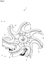
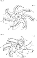
- the fan assembly (1) is suitable for use in a household appliance (2), in particular a cooking oven (2).
- the fan assembly (1) comprises a motor (3) which has a shaft (4) and a fan (5) which has a blade (6) and a hub (7).
- the hub (7) has a central bore (8) for supporting the shaft (4) ( Fig. 1 to 9 ).
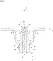
- the shaft (4) has a snap-fit connector (9a).
- the hub (7) has a counterpart snap-fit connector (9b) which engages with the snap-fit connector (9a) of the shaft (4) so as to secure the hub (7) against relative axial displacement with respect to the shaft (4).
- the shaft (4) has one or more than one anchoring rib (10).
- the hub (7) has a mating sleeve (11) for clamping the surface of the bore (8) against each anchoring rib (10) of the shaft (4) so as to secure the hub (7) against relative rotation with respect to the shaft (4).
- the snap-fit connector (9a) has a locking notch (12) which is formed into the circumferential surface of shaft (4).
- the counterpart snap-fit connector (9b) has one or more than one locking claw (13) for snap-fitting into the locking notch (12) as the shaft (4) is inserted into the bore (8).
- the counterpart snap-fit connector (9b) also has one or more than one resilient supporting arm (14). Each locking claw (13) is formed on the corresponding supporting arm (14).
- Each supporting arm (14) is formed onto the hub (7) and extends in an axial direction of the shaft (4). In the inserted state each locking claw (13) remains snap-fitted inside the locking notch (12) and secures the fan (5) against relative axial displacement with respect to the shaft (4).
- each supporting arm (14) is located on the free end of the hub (7) which is averted from the motor (3).
- the hub (7) has two supporting arms (14) which are diametrically opposed to each other.
- each anchoring rib (10) has a sawtooth shaped edge (10a) which is integrally formed onto the circumferential surface of the shaft (4) and protrudes a predetermined distance from the shaft (4).
- Each edge (10a) carves a mating groove into the inner surface of the bore (8) as the shaft (4) is inserted and clamped in the bore (8). In the clamped state each edge (10a) remains wedged inside the corresponding mating groove and secures the fan (5) against relative rotation with respect to the shaft (4).
- the fan assembly (1) comprises a gap (15) for rendering the hub (7) flexible.
- the gap (15) is formed into the hub (7).
- the sleeve (10) is clamped onto the hub (7) at the level of the gap (15).
- the fan assembly (1) comprises a stopper (16) for blocking a forward movement of the sleeve (11).
- the stopper (16) is formed onto the hub (7) at the level of the gap (15).
- the hub (7) comprises a cylindrical-shaped wall (17) which defines the bore (8).
- the gap (15) comprises two diametrically opposing slits (18) formed into the cylindrical-shaped wall (17).
- the sleeve (10) is ring-shaped and mates with the cylindrical-shaped wall (17).
- each anchoring rib (10) extends straight along the axial direction of the shaft (4).
- the shaft (4) has four anchoring ribs (10) which are evenly spaced around the axis of the shaft (4). Two of the anchoring ribs (10) are inclined towards the clockwise direction. The other two anchoring ribs (10) are inclined towards the anti-clockwise direction.
- the fan (5) is a single piece of plastic material which is heat resistant.
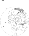
- the cooking oven (2) comprises a casing which encloses a cooking chamber for cooking food, a door for accessing the cooking chamber, a heater unit for heating the interior of the cooking chamber, a control unit which has a user-interface and a ventilation unit (19) for discharging hot air to the outside.
- the control unit controls the operation of the heater unit, the user-interface and the ventilation unit ( Fig. 1 to 9 ).
- the ventilation unit (19) comprises the fan assembly (1).
- the ventilation unit (19) further comprises a duct (20) for conveying the hot humid air to the outside.
- the duct (20) is disposed on and fluidly connected to the cooking chamber.
- the ventilation unit (19) further comprises an aperture (21) for immersing the fan (5) of the fan assembly (1) into the duct (20).
- the aperture (21) is formed into the duct (20) and is fluidly connected to a region in the proximity of the control unit.
- the ventilation unit (19) further comprises a frame (22) for retaining the motor (3) of the fan assembly (1).
- the frame (22) is detachably mountable around the aperture (21).
- the ventilation unit (19) is further configured to ventilate the door.
- the duct (20) is fluidly connected to one or more than one region in the proximity of the door.
- the structure of the fan assembly (1) has been simplified. Thereby, the need for utilizing the prior art thread connection has been obviated.
- the cost for production, assembly and maintenance of the fan assembly has been reduced.
- the present invention particularly the diameter of the shaft (4), the weight of the fan (5), the wattage of the motor (3) and the size of the motor (3) package have been substantially reduced. Thereby, the ventilation performance and the energy efficiency have also been improved. With the present invention the consumer satisfaction can be increased.
Landscapes
- Engineering & Computer Science (AREA)
- Mechanical Engineering (AREA)
- General Engineering & Computer Science (AREA)
- Structures Of Non-Positive Displacement Pumps (AREA)
- Connection Of Motors, Electrical Generators, Mechanical Devices, And The Like (AREA)
Claims (13)
- Un ensemble de ventilateur (1) destiné à être utilisé dans un appareil électroménager (2), en particulier dans un four de cuisson (2), l'ensemble de ventilateur (1) comprenant- un moteur (3) qui présente un arbre (4) et- un ventilateur (5) qui comporte une lame (6) et un moyeu (7), dont le moyeu (7) comporte un alésage central (8) pour supporter l'arbre (4),- l'arbre (4) qui comporte un connecteur à encliquetage (9a) et le moyeu (7) possède un connecteur à encliquetage homologue (9b) lesquels sont destinés à s'engager mutuellement et à sécuriser le moyeu (7) contre le déplacement axial relatif par rapport à l'arbre (4),
caractérisé en ce que- l'arbre (4) comporte une ou plusieurs nervure(s) d'ancrage (10) et le moyeu (7) comporte un manchon d'accouplement (11) conçu pour serrer la surface de l'alésage (8) contre chaque nervure d'ancrage (10) de l'arbre (4) et sécuriser le moyeu (7) contre la rotation relative par rapport à l'arbre (4),dans lequel chaque nervure d'ancrage (10) présente un bord en forme de dent de scie (10a) qui est intégralement formé sur la surface circonférentielle de l'arbre (4) et qui fait saillie d'une distance prédéterminée à partir de l'arbre (4), où chaque bord (10a) forme une rainure d'accouplement dans la surface interne de l'alésage (8) lorsque l'arbre (4) est inséré et serré dans l'alésage (8) et à l'état serré, chaque bord (10a) reste coincé à l'intérieur de la rainure d'accouplement correspondante et sécurise le ventilateur (5) contre la rotation relative par rapport à l'arbre (4). - Un ensemble de ventilateur (1) selon la revendication 1, caractérisé en ce que- le connecteur à encliquetage (9a) présente une encoche d'arrêt (12) qui est formée dans la surface circonférentielle de l'arbre (4) et- le connecteur à encliquetage homologue (9b) comporte une ou plusieurs griffes de verrouillage (13) configurées pour s'encliqueter dans l'encoche d'arrêt (12) lorsque l'arbre (4) est inséré dans l'alésage (8) et un ou plusieurs bras porteurs résilients (14), où chaque griffe de verrouillage (13) est formée sur le bras porteur correspondant (14) et dans lequel chaque bras porteur (14) est formé sur le moyeu (7) et s'étend dans la direction axiale de l'arbre (4) et, à l'état inséré, chaque griffe de verrouillage (13) reste encliquetée dans l'encoche d'arrêt (12) et sécurise le ventilateur (5) contre le déplacement axial relatif par rapport à l'arbre (4).
- L'ensemble de ventilateur (1) selon la revendication 2, caractérisé en ce que l'encoche d'arrêt (12) est située entre l'extrémité libre de l'arbre (4) et la nervure d'ancrage (10) et chaque bras porteur (14) est situé sur l'extrémité libre du moyeu (7) qui est éloignée du moteur (3).
- L'ensemble de ventilateur (1) selon la revendication 2 ou 3, caractérisé en ce que le moyeu (7) présente deux bras porteurs (14) qui sont diamétralement opposés entre eux.
- L'ensemble de ventilateur (1) selon l'une quelconque des revendications 1 à 4, caractérisé en ce qu'un écart (15) configuré afin de rendre le moyeu (7) flexible, dans lequel l'écart (15) est formé dans le moyeu (7) et dans lequel le manchon (10) est serré sur le moyeu (7) au niveau de l'écart (15).
- L'ensemble de ventilateur (1) selon la revendication 5, caractérisé en ce qu'un butoir (16) est configuré pour bloquer un mouvement avant du manchon (10), dans lequel le boutoir (16) est formé sur le moyeu (7) au niveau de l'écart (15).
- L'ensemble du ventilateur (1) selon la revendication 5 ou 6, caractérisé en ce que le moyeu (7) comprend une paroi de forme cylindrique (17) qui définit l'alésage (8) et en ce que l'écart (15) comprend deux fentes diamétralement opposées (18) formées dans la paroi de forme cylindrique (17), dans lequel le manchon (11) est de forme annulaire et s'accouple à la paroi de forme cylindrique (17).
- L'ensemble de ventilateur (1) selon l'une quelconque des revendications 1 à 7, caractérisé en ce que chaque nervure d'ancrage (10) s'étend en ligne droite dans la direction axiale de l'arbre (4).
- L'ensemble de ventilateur (1) selon l'une quelconque des revendications 1 à 8, caractérisé en ce que l'arbre (4) comporte quatre nervures d'ancrage (10) lesquelles sont espacées à intervalles réguliers autour de l'axe de l'arbre (4), où deux des nervures d'ancrage (10) sont inclinées dans le sens des aiguilles d'une montre et les deux autres nervures d'ancrage (10) sont inclinées dans le sens contraire des aiguilles d'une montre.
- L'ensemble de ventilateur (1) selon l'une quelconque des revendications 1 à 9, caractérisé en ce que le ventilateur (5) est une seule pièce en matière plastique.
- Un four de cuisson (2), en particulier un four de cuisson de type intégré (2) comprenant- un boîtier qui renferme une chambre de cuisson pour cuire les aliments,- une porte pour accéder à la chambre de cuisson,- une unité de chauffage pour chauffer l'intérieur de la chambre de cuisson,- une unité de contrôle dotée d'une interface utilisateur et- une unité de ventilation (19) pour décharger l'air chaud vers l'extérieur, où l'unité de contrôle commande l'unité de chauffage, l'interface utilisateur et l'unité de ventilation,caractérisé en ce que
l'unité de ventilation (19) comprend l'ensemble de ventilateur (1) tel que défini dans l'une quelconque des revendications 1 à 10. - Un four de cuisson (2) selon la revendication 11, caractérisé en ce que- un conduit (20) pour transmettre l'air chaud humide vers l'extérieur, où le conduit (20) est disposé sur et reliée par fluide à la chambre de cuisson,- une ouverture (21) pour immerger le ventilateur (5) de l'ensemble de ventilateur (1) dans le conduit (20), où l'ouverture (21) est formée dans le conduit (20) et est reliée par fluide à une région à proximité de l'unité de contrôle et- un cadre (22) pour retenir le moteur (3) de l'ensemble de ventilateur (1), où le cadre (22) peut être monté de manière amovible autour de l'ouverture (21).
- Un four de cuisson (2) selon la revendication 12, caractérisé en ce que l'unité de ventilation (19) est en outre configurée pour ventiler la porte, dans lequel le conduit (20) est reliée par fluide à une ou plusieurs régions à proximité de la porte.
Priority Applications (1)
| Application Number | Priority Date | Filing Date | Title |
|---|---|---|---|
| PL14777578T PL3201472T3 (pl) | 2014-09-29 | 2014-09-29 | Zespół wentylatora do piekarnika do gotowania o ulepszonym zużyciu energii |
Applications Claiming Priority (1)
| Application Number | Priority Date | Filing Date | Title |
|---|---|---|---|
| PCT/EP2014/070766 WO2016050259A1 (fr) | 2014-09-29 | 2014-09-29 | Ensemble ventilateur pour four de cuisson avec consommation d'énergie améliorée |
Publications (2)
| Publication Number | Publication Date |
|---|---|
| EP3201472A1 EP3201472A1 (fr) | 2017-08-09 |
| EP3201472B1 true EP3201472B1 (fr) | 2020-01-15 |
Family
ID=51655717
Family Applications (1)
| Application Number | Title | Priority Date | Filing Date |
|---|---|---|---|
| EP14777578.7A Active EP3201472B1 (fr) | 2014-09-29 | 2014-09-29 | Ensemble ventilateur pour four de cuisson avec consommation d'énergie améliorée |
Country Status (4)
| Country | Link |
|---|---|
| EP (1) | EP3201472B1 (fr) |
| PL (1) | PL3201472T3 (fr) |
| TR (1) | TR201511087A1 (fr) |
| WO (1) | WO2016050259A1 (fr) |
Family Cites Families (4)
| Publication number | Priority date | Publication date | Assignee | Title |
|---|---|---|---|---|
| US3367687A (en) * | 1966-01-27 | 1968-02-06 | General Electric Co. | Means to secure an element to a shaft |
| DE3223284A1 (de) * | 1982-06-22 | 1983-12-29 | Feinwerktechnik Schleicher & Co, 7778 Markdorf | Vorrichtung zur radialen und axialen verschiebungssicherung eines teils auf einer rotierenden welle |
| EP0356314A3 (fr) * | 1988-08-15 | 1990-05-16 | Akaishi Kinzoku Kogyo Co., Ltd. | Une turbine à plusieurs pales pour un ventilateur à courant transversal |
| IT216316Z2 (it) * | 1989-02-21 | 1991-07-17 | Bbs Spa | Girante per dispositivi aspiranti, il cui mozzo viene serrato al relativo perno di supporto tramite una molla elicoidale cilindrica |
-
2014
- 2014-09-29 EP EP14777578.7A patent/EP3201472B1/fr active Active
- 2014-09-29 WO PCT/EP2014/070766 patent/WO2016050259A1/fr not_active Ceased
- 2014-09-29 PL PL14777578T patent/PL3201472T3/pl unknown
-
2015
- 2015-09-07 TR TR2015/11087A patent/TR201511087A1/tr unknown
Non-Patent Citations (1)
| Title |
|---|
| None * |
Also Published As
| Publication number | Publication date |
|---|---|
| WO2016050259A1 (fr) | 2016-04-07 |
| PL3201472T3 (pl) | 2020-06-29 |
| TR201511087A1 (tr) | 2017-03-21 |
| EP3201472A1 (fr) | 2017-08-09 |
Similar Documents
| Publication | Publication Date | Title |
|---|---|---|
| RU2697544C1 (ru) | Держатель двигателя | |
| GB2553507B (en) | A handheld appliance | |
| US20200214499A1 (en) | Hot-air cooker | |
| EP3134653B1 (fr) | Pompe à chaleur et lave-vaisselle comprenant celle-ci | |
| JP2018518329A (ja) | 食品を攪拌または粉砕するための伸縮自在に移動可能な柄を伴う器具 | |
| JP2016529022A (ja) | 駆動機構に取り外し可能に係合する加工用具を含む電気調理機器 | |
| EP3201472B1 (fr) | Ensemble ventilateur pour four de cuisson avec consommation d'énergie améliorée | |
| CN108201339B (zh) | 降噪组件、破泡器及电压力锅 | |
| CN110604461B (zh) | 烹饪器具 | |
| US10808724B2 (en) | Rotor of an electric motor | |
| US9737125B2 (en) | Electric hairdryer with a motor protecting device | |
| JPWO2017212649A1 (ja) | 扇風機 | |
| CN112984763A (zh) | 空调器的导风机构以及具有其的空调器室内机 | |
| CN213514094U (zh) | 空调室内机以及具有其的空调器 | |
| EP2554913B1 (fr) | Appareil de cuisson avec agencement de couplage pour pièce d'accessoire | |
| CN211212573U (zh) | 锅体结构及烹饪器具 | |
| US20170030362A1 (en) | Vertical tower fanvertical tower fan and method for quickly assemblying and disassemblying the same | |
| CN113812745B (zh) | 包括减震器支撑件的吹风机 | |
| CN219613637U (zh) | 盖体组件和烹饪设备 | |
| EP3829384A1 (fr) | Sèche-cheveux électrique | |
| EP3647662A1 (fr) | Bouton de commande de poussée et d'expulsion pour appareil électroménager | |
| US20070017308A1 (en) | Manipulation device of microwave oven | |
| ATE376795T1 (de) | Drehwerkzeug fur elektrisches haushaltsgerät zur nahrungszubereitung | |
| EP2372254B1 (fr) | Cuisinière comprenant un couvercle et un ensemble pour assembler un conduit d'aération dans la face du couvercle | |
| CN212691900U (zh) | 自清洁风道组件及油烟机 |
Legal Events
| Date | Code | Title | Description |
|---|---|---|---|
| STAA | Information on the status of an ep patent application or granted ep patent |
Free format text: STATUS: THE INTERNATIONAL PUBLICATION HAS BEEN MADE |
|
| PUAI | Public reference made under article 153(3) epc to a published international application that has entered the european phase |
Free format text: ORIGINAL CODE: 0009012 |
|
| STAA | Information on the status of an ep patent application or granted ep patent |
Free format text: STATUS: REQUEST FOR EXAMINATION WAS MADE |
|
| 17P | Request for examination filed |
Effective date: 20170306 |
|
| AK | Designated contracting states |
Kind code of ref document: A1 Designated state(s): AL AT BE BG CH CY CZ DE DK EE ES FI FR GB GR HR HU IE IS IT LI LT LU LV MC MK MT NL NO PL PT RO RS SE SI SK SM TR |
|
| AX | Request for extension of the european patent |
Extension state: BA ME |
|
| DAX | Request for extension of the european patent (deleted) | ||
| RAP1 | Party data changed (applicant data changed or rights of an application transferred) |
Owner name: ARCELIK ANONIM SIRKETI |
|
| GRAP | Despatch of communication of intention to grant a patent |
Free format text: ORIGINAL CODE: EPIDOSNIGR1 |
|
| STAA | Information on the status of an ep patent application or granted ep patent |
Free format text: STATUS: GRANT OF PATENT IS INTENDED |
|
| INTG | Intention to grant announced |
Effective date: 20191105 |
|
| GRAS | Grant fee paid |
Free format text: ORIGINAL CODE: EPIDOSNIGR3 |
|
| GRAA | (expected) grant |
Free format text: ORIGINAL CODE: 0009210 |
|
| STAA | Information on the status of an ep patent application or granted ep patent |
Free format text: STATUS: THE PATENT HAS BEEN GRANTED |
|
| AK | Designated contracting states |
Kind code of ref document: B1 Designated state(s): AL AT BE BG CH CY CZ DE DK EE ES FI FR GB GR HR HU IE IS IT LI LT LU LV MC MK MT NL NO PL PT RO RS SE SI SK SM TR |
|
| REG | Reference to a national code |
Ref country code: CH Ref legal event code: EP Ref country code: GB Ref legal event code: FG4D |
|
| REG | Reference to a national code |
Ref country code: IE Ref legal event code: FG4D |
|
| REG | Reference to a national code |
Ref country code: AT Ref legal event code: REF Ref document number: 1225379 Country of ref document: AT Kind code of ref document: T Effective date: 20200215 |
|
| REG | Reference to a national code |
Ref country code: DE Ref legal event code: R096 Ref document number: 602014060079 Country of ref document: DE |
|
| REG | Reference to a national code |
Ref country code: RO Ref legal event code: EPE |
|
| REG | Reference to a national code |
Ref country code: NL Ref legal event code: MP Effective date: 20200115 |
|
| REG | Reference to a national code |
Ref country code: LT Ref legal event code: MG4D |
|
| PG25 | Lapsed in a contracting state [announced via postgrant information from national office to epo] |
Ref country code: RS Free format text: LAPSE BECAUSE OF FAILURE TO SUBMIT A TRANSLATION OF THE DESCRIPTION OR TO PAY THE FEE WITHIN THE PRESCRIBED TIME-LIMIT Effective date: 20200115 Ref country code: PT Free format text: LAPSE BECAUSE OF FAILURE TO SUBMIT A TRANSLATION OF THE DESCRIPTION OR TO PAY THE FEE WITHIN THE PRESCRIBED TIME-LIMIT Effective date: 20200607 Ref country code: NL Free format text: LAPSE BECAUSE OF FAILURE TO SUBMIT A TRANSLATION OF THE DESCRIPTION OR TO PAY THE FEE WITHIN THE PRESCRIBED TIME-LIMIT Effective date: 20200115 Ref country code: NO Free format text: LAPSE BECAUSE OF FAILURE TO SUBMIT A TRANSLATION OF THE DESCRIPTION OR TO PAY THE FEE WITHIN THE PRESCRIBED TIME-LIMIT Effective date: 20200415 Ref country code: FI Free format text: LAPSE BECAUSE OF FAILURE TO SUBMIT A TRANSLATION OF THE DESCRIPTION OR TO PAY THE FEE WITHIN THE PRESCRIBED TIME-LIMIT Effective date: 20200115 |
|
| PG25 | Lapsed in a contracting state [announced via postgrant information from national office to epo] |
Ref country code: IS Free format text: LAPSE BECAUSE OF FAILURE TO SUBMIT A TRANSLATION OF THE DESCRIPTION OR TO PAY THE FEE WITHIN THE PRESCRIBED TIME-LIMIT Effective date: 20200515 Ref country code: GR Free format text: LAPSE BECAUSE OF FAILURE TO SUBMIT A TRANSLATION OF THE DESCRIPTION OR TO PAY THE FEE WITHIN THE PRESCRIBED TIME-LIMIT Effective date: 20200416 Ref country code: HR Free format text: LAPSE BECAUSE OF FAILURE TO SUBMIT A TRANSLATION OF THE DESCRIPTION OR TO PAY THE FEE WITHIN THE PRESCRIBED TIME-LIMIT Effective date: 20200115 Ref country code: SE Free format text: LAPSE BECAUSE OF FAILURE TO SUBMIT A TRANSLATION OF THE DESCRIPTION OR TO PAY THE FEE WITHIN THE PRESCRIBED TIME-LIMIT Effective date: 20200115 Ref country code: LV Free format text: LAPSE BECAUSE OF FAILURE TO SUBMIT A TRANSLATION OF THE DESCRIPTION OR TO PAY THE FEE WITHIN THE PRESCRIBED TIME-LIMIT Effective date: 20200115 Ref country code: BG Free format text: LAPSE BECAUSE OF FAILURE TO SUBMIT A TRANSLATION OF THE DESCRIPTION OR TO PAY THE FEE WITHIN THE PRESCRIBED TIME-LIMIT Effective date: 20200415 |
|
| REG | Reference to a national code |
Ref country code: DE Ref legal event code: R097 Ref document number: 602014060079 Country of ref document: DE |
|
| PG25 | Lapsed in a contracting state [announced via postgrant information from national office to epo] |
Ref country code: DK Free format text: LAPSE BECAUSE OF FAILURE TO SUBMIT A TRANSLATION OF THE DESCRIPTION OR TO PAY THE FEE WITHIN THE PRESCRIBED TIME-LIMIT Effective date: 20200115 Ref country code: EE Free format text: LAPSE BECAUSE OF FAILURE TO SUBMIT A TRANSLATION OF THE DESCRIPTION OR TO PAY THE FEE WITHIN THE PRESCRIBED TIME-LIMIT Effective date: 20200115 Ref country code: SM Free format text: LAPSE BECAUSE OF FAILURE TO SUBMIT A TRANSLATION OF THE DESCRIPTION OR TO PAY THE FEE WITHIN THE PRESCRIBED TIME-LIMIT Effective date: 20200115 Ref country code: ES Free format text: LAPSE BECAUSE OF FAILURE TO SUBMIT A TRANSLATION OF THE DESCRIPTION OR TO PAY THE FEE WITHIN THE PRESCRIBED TIME-LIMIT Effective date: 20200115 Ref country code: LT Free format text: LAPSE BECAUSE OF FAILURE TO SUBMIT A TRANSLATION OF THE DESCRIPTION OR TO PAY THE FEE WITHIN THE PRESCRIBED TIME-LIMIT Effective date: 20200115 Ref country code: CZ Free format text: LAPSE BECAUSE OF FAILURE TO SUBMIT A TRANSLATION OF THE DESCRIPTION OR TO PAY THE FEE WITHIN THE PRESCRIBED TIME-LIMIT Effective date: 20200115 Ref country code: SK Free format text: LAPSE BECAUSE OF FAILURE TO SUBMIT A TRANSLATION OF THE DESCRIPTION OR TO PAY THE FEE WITHIN THE PRESCRIBED TIME-LIMIT Effective date: 20200115 |
|
| REG | Reference to a national code |
Ref country code: AT Ref legal event code: MK05 Ref document number: 1225379 Country of ref document: AT Kind code of ref document: T Effective date: 20200115 |
|
| PLBE | No opposition filed within time limit |
Free format text: ORIGINAL CODE: 0009261 |
|
| STAA | Information on the status of an ep patent application or granted ep patent |
Free format text: STATUS: NO OPPOSITION FILED WITHIN TIME LIMIT |
|
| 26N | No opposition filed |
Effective date: 20201016 |
|
| PG25 | Lapsed in a contracting state [announced via postgrant information from national office to epo] |
Ref country code: IT Free format text: LAPSE BECAUSE OF FAILURE TO SUBMIT A TRANSLATION OF THE DESCRIPTION OR TO PAY THE FEE WITHIN THE PRESCRIBED TIME-LIMIT Effective date: 20200115 Ref country code: AT Free format text: LAPSE BECAUSE OF FAILURE TO SUBMIT A TRANSLATION OF THE DESCRIPTION OR TO PAY THE FEE WITHIN THE PRESCRIBED TIME-LIMIT Effective date: 20200115 |
|
| PG25 | Lapsed in a contracting state [announced via postgrant information from national office to epo] |
Ref country code: SI Free format text: LAPSE BECAUSE OF FAILURE TO SUBMIT A TRANSLATION OF THE DESCRIPTION OR TO PAY THE FEE WITHIN THE PRESCRIBED TIME-LIMIT Effective date: 20200115 |
|
| PG25 | Lapsed in a contracting state [announced via postgrant information from national office to epo] |
Ref country code: MC Free format text: LAPSE BECAUSE OF FAILURE TO SUBMIT A TRANSLATION OF THE DESCRIPTION OR TO PAY THE FEE WITHIN THE PRESCRIBED TIME-LIMIT Effective date: 20200115 |
|
| REG | Reference to a national code |
Ref country code: CH Ref legal event code: PL |
|
| GBPC | Gb: european patent ceased through non-payment of renewal fee |
Effective date: 20200929 |
|
| REG | Reference to a national code |
Ref country code: BE Ref legal event code: MM Effective date: 20200930 |
|
| PG25 | Lapsed in a contracting state [announced via postgrant information from national office to epo] |
Ref country code: LU Free format text: LAPSE BECAUSE OF NON-PAYMENT OF DUE FEES Effective date: 20200929 |
|
| PG25 | Lapsed in a contracting state [announced via postgrant information from national office to epo] |
Ref country code: FR Free format text: LAPSE BECAUSE OF NON-PAYMENT OF DUE FEES Effective date: 20200930 |
|
| PG25 | Lapsed in a contracting state [announced via postgrant information from national office to epo] |
Ref country code: IE Free format text: LAPSE BECAUSE OF NON-PAYMENT OF DUE FEES Effective date: 20200929 Ref country code: GB Free format text: LAPSE BECAUSE OF NON-PAYMENT OF DUE FEES Effective date: 20200929 Ref country code: LI Free format text: LAPSE BECAUSE OF NON-PAYMENT OF DUE FEES Effective date: 20200930 Ref country code: BE Free format text: LAPSE BECAUSE OF NON-PAYMENT OF DUE FEES Effective date: 20200930 Ref country code: CH Free format text: LAPSE BECAUSE OF NON-PAYMENT OF DUE FEES Effective date: 20200930 |
|
| PG25 | Lapsed in a contracting state [announced via postgrant information from national office to epo] |
Ref country code: MT Free format text: LAPSE BECAUSE OF FAILURE TO SUBMIT A TRANSLATION OF THE DESCRIPTION OR TO PAY THE FEE WITHIN THE PRESCRIBED TIME-LIMIT Effective date: 20200115 Ref country code: CY Free format text: LAPSE BECAUSE OF FAILURE TO SUBMIT A TRANSLATION OF THE DESCRIPTION OR TO PAY THE FEE WITHIN THE PRESCRIBED TIME-LIMIT Effective date: 20200115 |
|
| PG25 | Lapsed in a contracting state [announced via postgrant information from national office to epo] |
Ref country code: MK Free format text: LAPSE BECAUSE OF FAILURE TO SUBMIT A TRANSLATION OF THE DESCRIPTION OR TO PAY THE FEE WITHIN THE PRESCRIBED TIME-LIMIT Effective date: 20200115 Ref country code: AL Free format text: LAPSE BECAUSE OF FAILURE TO SUBMIT A TRANSLATION OF THE DESCRIPTION OR TO PAY THE FEE WITHIN THE PRESCRIBED TIME-LIMIT Effective date: 20200115 |
|
| PGFP | Annual fee paid to national office [announced via postgrant information from national office to epo] |
Ref country code: DE Payment date: 20250919 Year of fee payment: 12 |
|
| PGFP | Annual fee paid to national office [announced via postgrant information from national office to epo] |
Ref country code: TR Payment date: 20250918 Year of fee payment: 12 Ref country code: PL Payment date: 20250923 Year of fee payment: 12 |
|
| PGFP | Annual fee paid to national office [announced via postgrant information from national office to epo] |
Ref country code: RO Payment date: 20250922 Year of fee payment: 12 |