EP3200700B1 - Biopsy kit - Google Patents
Biopsy kit Download PDFInfo
- Publication number
- EP3200700B1 EP3200700B1 EP15847271.2A EP15847271A EP3200700B1 EP 3200700 B1 EP3200700 B1 EP 3200700B1 EP 15847271 A EP15847271 A EP 15847271A EP 3200700 B1 EP3200700 B1 EP 3200700B1
- Authority
- EP
- European Patent Office
- Prior art keywords
- cutting
- penetration rod
- biopsy
- target tissue
- cutting device
- Prior art date
- Legal status (The legal status is an assumption and is not a legal conclusion. Google has not performed a legal analysis and makes no representation as to the accuracy of the status listed.)
- Active
Links
- 238000001574 biopsy Methods 0.000 title claims description 57
- 230000035515 penetration Effects 0.000 claims description 67
- 238000000034 method Methods 0.000 description 18
- 238000001356 surgical procedure Methods 0.000 description 7
- 230000000740 bleeding effect Effects 0.000 description 5
- 206010028980 Neoplasm Diseases 0.000 description 4
- 230000000149 penetrating effect Effects 0.000 description 4
- 208000027418 Wounds and injury Diseases 0.000 description 3
- 230000006378 damage Effects 0.000 description 3
- 208000014674 injury Diseases 0.000 description 3
- 239000000463 material Substances 0.000 description 3
- 210000005036 nerve Anatomy 0.000 description 3
- 238000007789 sealing Methods 0.000 description 3
- 210000004204 blood vessel Anatomy 0.000 description 2
- 238000010899 nucleation Methods 0.000 description 2
- 210000004881 tumor cell Anatomy 0.000 description 2
- 239000008280 blood Substances 0.000 description 1
- 210000004369 blood Anatomy 0.000 description 1
- 201000011510 cancer Diseases 0.000 description 1
- 238000005516 engineering process Methods 0.000 description 1
- 239000012530 fluid Substances 0.000 description 1
- 210000004907 gland Anatomy 0.000 description 1
- 238000003306 harvesting Methods 0.000 description 1
- 238000003384 imaging method Methods 0.000 description 1
- 238000013188 needle biopsy Methods 0.000 description 1
- 230000001954 sterilising effect Effects 0.000 description 1
- 238000004659 sterilization and disinfection Methods 0.000 description 1
- 238000002604 ultrasonography Methods 0.000 description 1
Images
Classifications
-
- A—HUMAN NECESSITIES
- A61—MEDICAL OR VETERINARY SCIENCE; HYGIENE
- A61B—DIAGNOSIS; SURGERY; IDENTIFICATION
- A61B10/00—Other methods or instruments for diagnosis, e.g. instruments for taking a cell sample, for biopsy, for vaccination diagnosis; Sex determination; Ovulation-period determination; Throat striking implements
- A61B10/02—Instruments for taking cell samples or for biopsy
- A61B10/0233—Pointed or sharp biopsy instruments
-
- A—HUMAN NECESSITIES
- A61—MEDICAL OR VETERINARY SCIENCE; HYGIENE
- A61B—DIAGNOSIS; SURGERY; IDENTIFICATION
- A61B10/00—Other methods or instruments for diagnosis, e.g. instruments for taking a cell sample, for biopsy, for vaccination diagnosis; Sex determination; Ovulation-period determination; Throat striking implements
- A61B10/02—Instruments for taking cell samples or for biopsy
- A61B10/0233—Pointed or sharp biopsy instruments
- A61B10/0266—Pointed or sharp biopsy instruments means for severing sample
- A61B10/0275—Pointed or sharp biopsy instruments means for severing sample with sample notch, e.g. on the side of inner stylet
-
- A—HUMAN NECESSITIES
- A61—MEDICAL OR VETERINARY SCIENCE; HYGIENE
- A61B—DIAGNOSIS; SURGERY; IDENTIFICATION
- A61B10/00—Other methods or instruments for diagnosis, e.g. instruments for taking a cell sample, for biopsy, for vaccination diagnosis; Sex determination; Ovulation-period determination; Throat striking implements
- A61B10/02—Instruments for taking cell samples or for biopsy
- A61B10/0233—Pointed or sharp biopsy instruments
- A61B10/0283—Pointed or sharp biopsy instruments with vacuum aspiration, e.g. caused by retractable plunger or by connected syringe
-
- A—HUMAN NECESSITIES
- A61—MEDICAL OR VETERINARY SCIENCE; HYGIENE
- A61B—DIAGNOSIS; SURGERY; IDENTIFICATION
- A61B18/00—Surgical instruments, devices or methods for transferring non-mechanical forms of energy to or from the body
-
- A—HUMAN NECESSITIES
- A61—MEDICAL OR VETERINARY SCIENCE; HYGIENE
- A61B—DIAGNOSIS; SURGERY; IDENTIFICATION
- A61B18/00—Surgical instruments, devices or methods for transferring non-mechanical forms of energy to or from the body
- A61B18/04—Surgical instruments, devices or methods for transferring non-mechanical forms of energy to or from the body by heating
- A61B18/12—Surgical instruments, devices or methods for transferring non-mechanical forms of energy to or from the body by heating by passing a current through the tissue to be heated, e.g. high-frequency current
- A61B18/14—Probes or electrodes therefor
- A61B18/1477—Needle-like probes
Definitions
- the present invention relates generally to a biopsy kit for removal of a piece of target tissue.
- US4461305 shows an automated biopsy device using a motor driven unit to cut from a surface into a body a depth decided of a plunger.
- a distal cutting blade is rotatable into a cutting off position from a circumference of a distal end of a core cutter.
- US2003/0023239 A1 shows a biopsy instrument using radial vacuum around a central tube in order to position target tissue in position for cutting off.
- US2009/0227895 A1 shows a biopsy needle having a stylet arranged in a cutting tube. A coil is used to snare a target tissue off.
- WO00/12010 shows a biopsy instrument for harvesting larger target tissue than the lumen of the instrument.
- a fast and efficient technique for removing pieces of target tissue, for example core biopsies, specifically from deeply situated target areas is provided. It also provides a minimally invasive technique with minimal scaring, minimal bleeding and minimal injuries to surrounding tissue and nerves and only extracting target tissue.
- the present technique enables high precision core biopsies to be performed manually, possibly by one hand only, and it is ideal to use with high quality imaging systems, for example state of the art ultrasound. It is simple, safe and fast procedure compared to other core biopsy methods.
- the kit is a low cost instrument compared to previously used instruments and is preferably disposable, which allows safe and guarantied sterilization, ready to use and simple distribution and handling. By having kits of varying sizes, length and/or diameter, a suitable kit can be chosen for each surgery/biopsy. It is also possible to use as a kit and a method for surgery with all the above advantages.
- An object of the present invention is to provide a cost effective biopsy kit. Another object of the present invention is to provide a biopsy kit, which is easy to handle. Additionally, it is an object to provide a safe biopsy kit and to provide the possibility to totally remove tumors en bloc.
- a biopsy kit according to claim 1 is provided.
- the distal end portion of the penetration rod is blunt.
- kits having a blunt penetration rod it is possible to penetrate all the way into the position before the target area or biopsy position without cutting tissue. Instead the penetration rod will separate the tissue while penetrating the body. Thus, bleeding and the risk of injuries to nerves, blood vessels and surrounding tissue will be minimized.
- the present kit is also possible to use manually without the need of stereotactic systems, although it is of course possible to arrange the present instrument in such a system.
- the penetration rod, cutting device and the cutting tube are arranged coaxially along an axis.
- the cutting device is rotatable around the axis and the cutting means extend radially from the axis.
- the cutting device is extendable from the penetration rod in an axial direction.
- the cutting device may take a first position where the cutting device is protected by the penetration rod, a second position where the cutting means (5) extends just enough to be able to cut tissue at the distal end portion (3) of the penetration rod (2) or a third position where the cutting means (5) extends through the piece of target tissue in order to be able to cut off the piece of target tissue.
- the second position it is possible to cut during the penetration on its way to the target area. For example, if the penetration rod needs to get through harder tissue.
- the cutting means of the cutting device is an electrode for diathermy.
- the cutting device comprises an electrical connector for the electrode. It is also preferable to protect the electrical connector by insulating means.
- the advantage of having diathermy electrodes is that there will be no or minimized bleeding during cutting in the tissue.
- a sealing means is provided between the penetration rod and the cutting tube and/or between the penetration rod and the cutting device.
- a negative pressure or vacuum is possible to provide during use by means of axial movement of the penetration rod. Due to the vacuum a more secure taking of the biopsy is provided and additionally a less risk of losing the taken biopsy material during withdrawal of the instrument is provided.
- the vacuum also facilitates the cutting of the target tissue by pulling the tissue into the container.
- a negative pressure may also be applied from an external source. The negative pressure may also be used for evacuating blood or other fluids.
- a second tube is arranged concentrically outside the cutting tube. In this way it is possible to minimize the risk of seeding tumor cells in the penetration channel, which is made by the biopsy kit, during withdrawal of the biopsy kit by means of keeping the second tube in the penetration channel during the withdrawal of the biopsy kit. Thereafter the second tube can be removed from the body.
- the biopsy instrument is operable with only one hand.
- a non-claimed method of removal of a piece of target tissue from a body comprises the steps
- the non-claimed method uses diathermy connected to the cutting means (5) of the cutting device in one embodiment.
- the non-claimed method provides negative pressure to the biopsy kit.
- the non-claimed method comprises extending the cutting device from the penetration rod from a first position, where the cutting means is protected by the penetration rod, to a second position where the cutting means extends just enough to be able to cut tissue at the distal end portion of the penetration rod, and cutting tissue with the cutting means in the second position.
- a biopsy kit 1 for removal of a piece of target tissue from a body comprising at least a penetration rod 2, preferably having a blunt distal end 3, a cutting device 4 and a cutting tube 6.
- a penetration rod 2 preferably having a blunt distal end 3, a cutting device 4 and a cutting tube 6.
- Fig. 1a a cutting tube 6 is shown and the cutting tube has a distal circumventing cutting edge 7.
- the cutting tube 6 is enclosing a penetration rod 2, see Fig. 1b , and is axially extendable from the distal end portion 3 of the penetration rod 2 in a distal direction for cutting and enclosing a piece of target tissue.
- FIG. 1b An embodiment of a penetration rod 2 is shown in Fig. 1b . It is for penetrating into the body up to the target area.
- a cutting device 4 is shown in Fig. 1c . It is extendable from the penetration rod 2 and comprises cutting means 5 for cutting off the piece of target tissue from the body.
- the cutting device 4 is centrally provided inside of the penetration rod 2.
- a cut 10 is shown in the distal end portion 3 of the penetration rod 2. When the cutting device 4 is in its first position it is protected inside of the penetration rod 2 and also the cutting means 5 of the cutting device 4 is protected within the penetration rod 2.
- the cutting device 4 is preferably elongated of any cross section, although a circular cross section may be preferable.
- cutting means 5 is provided, which extends radially from the cutting device 4.
- the cutting means 5 is for cutting off a piece of target tissue to be harvested.
- the cutting means 5 may have any conceivable shape, such as an L-shape, T-shape, leaf-shape corresponding with the outer shape of the distal end portion 3 of the penetration rod 2, or one or two pin cutters having the shape of the outer shape of the distal end portion 3, for example.
- the radial distance of the extension of the cutting means 5 corresponds preferably with the radius of the cutting tube 6.
- the cutting means 5 could be sharp for mechanical cutting or electrodes for diathermy, for example surgical or monopolar diathermy. If the cutting means 5 is an electrode the cutting device is a connector 8, see Fig. 1c , and insulating means 9 as shown in Fig. 1d is needed.
- Fig. 1e the kit is shown in an assembled way.
- the cutting tube 6 is extended axially out from the distal end 3 of the penetration rod 2.
- the cutting device 4 is extended axially out from the distal end 3 of the penetration rod 2.
- the biopsy kit is preferably arranged coaxially around an axis x.
- a second position is when the cutting device 4 is extended shortly out of the penetration rod 2 so that the cutting means 5 is just outside the distal end portion 3 of the penetration rod 2. In this position it is possible to cut during the penetration on its way to the target area. For example, if the penetration rod 2 needs to get through harder tissue as a gland or the like. This is possible both with the embodiment having sharp cutting means 5 and diathermy electrodes as cutting means 5. The advantage of having diathermy electrodes in this case when the penetration rod 2 needs to penetrate harder tissue is that there will be no bleeding.
- a third position is when the cutting device 4 is extended so far that it has passed through the piece of target tissue to be harvested and thus can be used to cut off the piece of target tissue at its distal end by means of the cutting means 5. Also this is possible both with the embodiment having sharp cutting means 5 and diathermy electrodes as cutting means 5.
- a sealing means may be provided for sealingly fitting with the cutting tube 6.
- a vacuum will be built up in the space that forms between the blunt end of the penetration rod 2 and the distal end of the cutting tube 6. This would facilitate the taking of the biopsy and secure a taken biopsy to remain in the inner tube during withdrawal of the instrument from the body. It is also conceivable to increase the vacuum by having a hole through the penetration rod and connect the penetration rod to a suction pump. Another way is to leave out the sealing means and connect the suction pump to the biopsy taking device.
- the penetration rod may be pushed back into the cutting tube in a distal direction when outside of the body.
- an outer tube too. This will be arranged concentrically outside the cutting tube before the biopsy instrument is penetrated into the body. This outer tube is kept in the penetration channel while the biopsy instrument is removed and thereafter removed. Thus it is possible to minimize the risk of seeding of tumor cells in the penetration channel.
- a non-claimed method of removal of a piece of target tissue from a body is provided. where a biopsy kit 1 is entered into a body through a small skin incision and pushed into a starting position in front of a target tissue area, i.e. when reaching the piece of target tissue to be removed.
- the biopsy kit 1 comprises at least a penetration rod 2 with preferably a blunt distal end 3, a cutting device 4, and a cutting tube 6.
- the blunt penetration rod 2 will separate the tissue while penetrating the body and thus it is possible to move all the way into the position before the biopsy position without cutting tissue. Thus, almost no bleeding will occur and the risk of injuries to the nerves, blood vessels and surrounding tissue will decrease.
- surgeon may choose three different paths to carry out the method. They will be described one by one hereafter. According to a first path the surgeon may withdraw the penetration rod 2 into the cutting tube 6 leaving a space between the distal end of the cutting tube 6 and the distal end of the penetration rod 2, but it is optional.
- the surgeon thereafter pushes axially in the distal direction, and preferably rotating back and forth, the cutting tube 6 further into the body cutting with the sharp distal cutting edge 7 so that the piece of target tissue enters into said space and then extending the cutting device 4 axially in the distal direction, which cuts through the piece of target tissue.
- a cutting means 5 of the cutting device 4 is used, preferably rotated, to cut off the piece of target tissue.
- the piece of target tissue may be cut off within the cutting tube 6 or just outside the cutting edge of the cutting tube 6.
- the biopsy instrument is withdrawn from the body. By pushing the penetration rod 2 forward, when outside of the body, the biopsy material will be pushed out of the cutting tube 6.
- the cutting device 4 is extended through the piece of target tissue. Thereafter, the cutting tube 6 is pushed forward enclosing the piece of target tissue, preferably as far in as the cutting device 4 was extended. Then the cutting means 5 is used to cut off the piece of target tissue. Thereafter the biopsy instrument is withdrawn from the body.
- the cutting device 4 is extended through the piece of target tissue. Thereafter, the cutting means 5 is used, preferably rotated, to cut off the distal end of the piece of target tissue. Then the cutting tube 6 is pushed forward enclosing the piece of target tissue, as far in as the cutting device 4 was extended so that the cutting tube 6 reaches the cut off distal end of the piece of target tissue. Thereafter the biopsy instrument is withdrawn from the body.
- the cutting means 5 cuts off the piece of target tissue in its distal end against or in close vicinity to the inside of the distal end portion of the cutting tube 6. It is also conceivable to cut off the tissue just outside of the cutting edge of the cutting tube 6. It is also possible to cut off the piece of target tissue at any position along the inside of the cutting tube 6.
- the cutting means may cut mechanically or by means of diathermy, preferably while rotating the cutting device 4.
- Biopsy kits may be provided in different sizes for different uses. Cutting tube 6 diameters may for example be 2-25 mm, preferably 4-15 mm. When using larger kits it may be possible to not only take a biopsy but at the same time perform the needed surgery. This could be useful in cancer treatment, for example, when a small tumor can be removed directly without the need to first take out a biopsy and analyze it and then perform the surgery. The need of surgery under seduction will be removed. Additionally, it is usually easier to locate the right position when using ultrasonic technology or radiology to identify the position of small tumors compared to when using open surgery. The biopsy kit and the corresponding method would reduce costs for surgery.
Description
- The present invention relates generally to a biopsy kit for removal of a piece of target tissue.
- In prior art biopsy instruments are known which are either fine needle biopsy instruments which are easy to use and low cost but the results are not always reliable or very complicated and expensive and usually used in systems like stereotactic systems.
-
US4461305 shows an automated biopsy device using a motor driven unit to cut from a surface into a body a depth decided of a plunger. A distal cutting blade is rotatable into a cutting off position from a circumference of a distal end of a core cutter. -
US2003/0023239 A1 shows a biopsy instrument using radial vacuum around a central tube in order to position target tissue in position for cutting off. -
US2009/0227895 A1 shows a biopsy needle having a stylet arranged in a cutting tube. A coil is used to snare a target tissue off. -
WO00/12010 - With the present biopsy kit and method of removal of a piece of target tissue a fast and efficient technique for removing pieces of target tissue, for example core biopsies, specifically from deeply situated target areas is provided. It also provides a minimally invasive technique with minimal scaring, minimal bleeding and minimal injuries to surrounding tissue and nerves and only extracting target tissue.
- The present technique enables high precision core biopsies to be performed manually, possibly by one hand only, and it is ideal to use with high quality imaging systems, for example state of the art ultrasound. It is simple, safe and fast procedure compared to other core biopsy methods. The kit is a low cost instrument compared to previously used instruments and is preferably disposable, which allows safe and guarantied sterilization, ready to use and simple distribution and handling. By having kits of varying sizes, length and/or diameter, a suitable kit can be chosen for each surgery/biopsy. It is also possible to use as a kit and a method for surgery with all the above advantages.
- An object of the present invention is to provide a cost effective biopsy kit. Another object of the present invention is to provide a biopsy kit, which is easy to handle. Additionally, it is an object to provide a safe biopsy kit and to provide the possibility to totally remove tumors en bloc.
- In order to try to fulfill the objects, a biopsy kit according to
claim 1 is provided. - Preferably the distal end portion of the penetration rod is blunt.
- With such a kit having a blunt penetration rod it is possible to penetrate all the way into the position before the target area or biopsy position without cutting tissue. Instead the penetration rod will separate the tissue while penetrating the body. Thus, bleeding and the risk of injuries to nerves, blood vessels and surrounding tissue will be minimized. The present kit is also possible to use manually without the need of stereotactic systems, although it is of course possible to arrange the present instrument in such a system.
- According to the invention the penetration rod, cutting device and the cutting tube are arranged coaxially along an axis.
- According to invention the cutting device is rotatable around the axis and the cutting means extend radially from the axis.
- According to the invention the cutting device is extendable from the penetration rod in an axial direction. In one embodiment, the cutting device may take a first position where the cutting device is protected by the penetration rod, a second position where the cutting means (5) extends just enough to be able to cut tissue at the distal end portion (3) of the penetration rod (2) or a third position where the cutting means (5) extends through the piece of target tissue in order to be able to cut off the piece of target tissue. In the second position it is possible to cut during the penetration on its way to the target area. For example, if the penetration rod needs to get through harder tissue.
- Preferably the cutting means of the cutting device is an electrode for diathermy. In such an embodiment it is preferred that the cutting device comprises an electrical connector for the electrode. It is also preferable to protect the electrical connector by insulating means. The advantage of having diathermy electrodes is that there will be no or minimized bleeding during cutting in the tissue.
- According to one embodiment, a sealing means is provided between the penetration rod and the cutting tube and/or between the penetration rod and the cutting device. Thus it is possible to provide vacuum in the distal end of the biopsy kit.
- As previously mentioned a negative pressure or vacuum is possible to provide during use by means of axial movement of the penetration rod. Due to the vacuum a more secure taking of the biopsy is provided and additionally a less risk of losing the taken biopsy material during withdrawal of the instrument is provided. The vacuum also facilitates the cutting of the target tissue by pulling the tissue into the container. A negative pressure may also be applied from an external source. The negative pressure may also be used for evacuating blood or other fluids.
- In a further embodiment a second tube is arranged concentrically outside the cutting tube. In this way it is possible to minimize the risk of seeding tumor cells in the penetration channel, which is made by the biopsy kit, during withdrawal of the biopsy kit by means of keeping the second tube in the penetration channel during the withdrawal of the biopsy kit. Thereafter the second tube can be removed from the body.
- Preferably, the biopsy instrument is operable with only one hand.
- A non-claimed method of removal of a piece of target tissue from a body is also provided. The method comprises the steps
- penetrating tissue of the body using a penetration rod,
- upon reaching the piece of target tissue to be removed, carrying out the following two steps in any consecutive order,
- extending a cutting device from the penetration rod to penetrate the piece of target tissue,
- extending a cutting tube from the penetration rod to cut out and enclose the piece of target tissue,
and additionally - cutting off the piece of target tissue using a cutting means of the cutting device after extending the cutting device either before or after extending the cutting tube.
- The non-claimed method uses diathermy connected to the cutting means (5) of the cutting device in one embodiment.
- The non-claimed method provides negative pressure to the biopsy kit.
- The non-claimed method comprises extending the cutting device from the penetration rod from a first position, where the cutting means is protected by the penetration rod, to a second position where the cutting means extends just enough to be able to cut tissue at the distal end portion of the penetration rod, and cutting tissue with the cutting means in the second position.
- The invention is now described, by way of example, with reference to the accompanying drawings, in which:
-
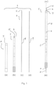
Fig. 1a shows one embodiment of a cutting tube, -
Fig. 1b shows one embodiment of a penetration rod, -
Fig. 1c shows one embodiment of a cutting device, -
Fig. 1d shows one embodiment of insulating means, and -
Fig. 1e shows one embodiment of a kit assembled. - In the following, a
biopsy kit 1 in different embodiments and a non-claimed method for - A
biopsy kit 1 for removal of a piece of target tissue from a body is provided comprising at least apenetration rod 2, preferably having a bluntdistal end 3, a cutting device 4 and a cutting tube 6. InFig. 1a a cutting tube 6 is shown and the cutting tube has a distalcircumventing cutting edge 7. The cutting tube 6 is enclosing apenetration rod 2, seeFig. 1b , and is axially extendable from thedistal end portion 3 of thepenetration rod 2 in a distal direction for cutting and enclosing a piece of target tissue. - An embodiment of a
penetration rod 2 is shown inFig. 1b . It is for penetrating into the body up to the target area. InFig. 1c a cutting device 4 is shown. It is extendable from thepenetration rod 2 and comprises cutting means 5 for cutting off the piece of target tissue from the body. The cutting device 4 is centrally provided inside of thepenetration rod 2. InFig. 1b acut 10 is shown in thedistal end portion 3 of thepenetration rod 2. When the cutting device 4 is in its first position it is protected inside of thepenetration rod 2 and also the cutting means 5 of the cutting device 4 is protected within thepenetration rod 2. - The cutting device 4 is preferably elongated of any cross section, although a circular cross section may be preferable. In its distal end cutting means 5 is provided, which extends radially from the cutting device 4. The cutting means 5 is for cutting off a piece of target tissue to be harvested. The cutting means 5 may have any conceivable shape, such as an L-shape, T-shape, leaf-shape corresponding with the outer shape of the
distal end portion 3 of thepenetration rod 2, or one or two pin cutters having the shape of the outer shape of thedistal end portion 3, for example. The radial distance of the extension of the cutting means 5 corresponds preferably with the radius of the cutting tube 6. - The cutting means 5 could be sharp for mechanical cutting or electrodes for diathermy, for example surgical or monopolar diathermy. If the cutting means 5 is an electrode the cutting device is a connector 8, see
Fig. 1c , and insulatingmeans 9 as shown inFig. 1d is needed. - In
Fig. 1e the kit is shown in an assembled way. In theFig. 1e the cutting tube 6 is extended axially out from thedistal end 3 of thepenetration rod 2. Also the cutting device 4 is extended axially out from thedistal end 3 of thepenetration rod 2. The biopsy kit is preferably arranged coaxially around an axis x. - Previously the first position of the cutting device 4 was explained. A second position is when the cutting device 4 is extended shortly out of the
penetration rod 2 so that the cutting means 5 is just outside thedistal end portion 3 of thepenetration rod 2. In this position it is possible to cut during the penetration on its way to the target area. For example, if thepenetration rod 2 needs to get through harder tissue as a gland or the like. This is possible both with the embodiment having sharp cutting means 5 and diathermy electrodes as cutting means 5. The advantage of having diathermy electrodes in this case when thepenetration rod 2 needs to penetrate harder tissue is that there will be no bleeding. - A third position is when the cutting device 4 is extended so far that it has passed through the piece of target tissue to be harvested and thus can be used to cut off the piece of target tissue at its distal end by means of the cutting means 5. Also this is possible both with the embodiment having sharp cutting means 5 and diathermy electrodes as cutting means 5.
- In the vicinity of the distal end of the penetration rod a sealing means may be provided for sealingly fitting with the cutting tube 6. When a withdrawal of the
penetration rod 2 is performed a vacuum will be built up in the space that forms between the blunt end of thepenetration rod 2 and the distal end of the cutting tube 6. This would facilitate the taking of the biopsy and secure a taken biopsy to remain in the inner tube during withdrawal of the instrument from the body. It is also conceivable to increase the vacuum by having a hole through the penetration rod and connect the penetration rod to a suction pump. Another way is to leave out the sealing means and connect the suction pump to the biopsy taking device. - In order to remove the taken biopsy material, i.e. piece of target tissue, collected inside of the cutting tube the penetration rod may be pushed back into the cutting tube in a distal direction when outside of the body.
- It is also conceivable to use an outer tube, too. This will be arranged concentrically outside the cutting tube before the biopsy instrument is penetrated into the body. This outer tube is kept in the penetration channel while the biopsy instrument is removed and thereafter removed. Thus it is possible to minimize the risk of seeding of tumor cells in the penetration channel.
- A non-claimed method of removal of a piece of target tissue from a body is provided. where a
biopsy kit 1 is entered into a body through a small skin incision and pushed into a starting position in front of a target tissue area, i.e. when reaching the piece of target tissue to be removed. Thebiopsy kit 1 comprises at least apenetration rod 2 with preferably a bluntdistal end 3, a cutting device 4, and a cutting tube 6. - The
blunt penetration rod 2 will separate the tissue while penetrating the body and thus it is possible to move all the way into the position before the biopsy position without cutting tissue. Thus, almost no bleeding will occur and the risk of injuries to the nerves, blood vessels and surrounding tissue will decrease. - Thereafter, the surgeon may choose three different paths to carry out the method. They will be described one by one hereafter. According to a first path the surgeon may withdraw the
penetration rod 2 into the cutting tube 6 leaving a space between the distal end of the cutting tube 6 and the distal end of thepenetration rod 2, but it is optional. - The surgeon thereafter pushes axially in the distal direction, and preferably rotating back and forth, the cutting tube 6 further into the body cutting with the sharp
distal cutting edge 7 so that the piece of target tissue enters into said space and then extending the cutting device 4 axially in the distal direction, which cuts through the piece of target tissue. When the cutting device 4 has passed through the piece of target tissue, and is preferably in line with the distal end of the cutting tube 6, a cutting means 5 of the cutting device 4 is used, preferably rotated, to cut off the piece of target tissue. The piece of target tissue may be cut off within the cutting tube 6 or just outside the cutting edge of the cutting tube 6. Thereafter the biopsy instrument is withdrawn from the body. By pushing thepenetration rod 2 forward, when outside of the body, the biopsy material will be pushed out of the cutting tube 6. - According to a second path of carrying out the method, the cutting device 4 is extended through the piece of target tissue. Thereafter, the cutting tube 6 is pushed forward enclosing the piece of target tissue, preferably as far in as the cutting device 4 was extended. Then the cutting means 5 is used to cut off the piece of target tissue. Thereafter the biopsy instrument is withdrawn from the body.
- According to a third path of carrying out the method, the cutting device 4 is extended through the piece of target tissue. Thereafter, the cutting means 5 is used, preferably rotated, to cut off the distal end of the piece of target tissue. Then the cutting tube 6 is pushed forward enclosing the piece of target tissue, as far in as the cutting device 4 was extended so that the cutting tube 6 reaches the cut off distal end of the piece of target tissue. Thereafter the biopsy instrument is withdrawn from the body.
- In a preferred embodiment the cutting means 5 cuts off the piece of target tissue in its distal end against or in close vicinity to the inside of the distal end portion of the cutting tube 6. It is also conceivable to cut off the tissue just outside of the cutting edge of the cutting tube 6. It is also possible to cut off the piece of target tissue at any position along the inside of the cutting tube 6. The cutting means may cut mechanically or by means of diathermy, preferably while rotating the cutting device 4.
- Biopsy kits may be provided in different sizes for different uses. Cutting tube 6 diameters may for example be 2-25 mm, preferably 4-15 mm. When using larger kits it may be possible to not only take a biopsy but at the same time perform the needed surgery. This could be useful in cancer treatment, for example, when a small tumor can be removed directly without the need to first take out a biopsy and analyze it and then perform the surgery. The need of surgery under seduction will be removed. Additionally, it is usually easier to locate the right position when using ultrasonic technology or radiology to identify the position of small tumors compared to when using open surgery. The biopsy kit and the corresponding method would reduce costs for surgery.
Claims (10)
- A biopsy kit (1) for removal of a piece of target tissue from a body, comprisinga penetration rod (2) having a distal end portion (3) for penetration into the body, a cutting tube (6) enclosing the penetration rod, comprising circumventing cutting means (7), the cutting tube being extendable from the distal end portion of the penetration rod for cutting and enclosing the piece of target tissue, whereina cutting device (4) is centrally provided inside of the penetration rod (2), wherein the penetration rod (2), the cutting device (4) and the cutting tube (6) are arranged coaxially along an axis (x), the cutting device (4) is extendable distally from the penetration rod along the axis (x), and comprises distal cutting means (5) extending radially out from the axis (x) for cutting off the piece of target tissue from the body, and wherein the cutting device (4) is rotatable around the axis.
- The biopsy kit according to claim 1, wherein the distal end portion (3) of the penetration rod is blunt.
- The biopsy kit according to claim 1 or 2, wherein the cutting device (4) is extendable from the penetration rod (2) from a first position, where the distal cutting means (5) is protected by the penetration rod (2).
- The biopsy kit according to any one of the preceding claims, wherein the cutting device (4) is extendable from the penetration rod (2) from a first position, where the distal cutting means (5) is protected by the penetration rod (2), to a second position where the distal cutting means (5) extends just enough to be able to cut tissue at the distal end portion (3) of the penetration rod (2).
- The biopsy kit according to any one of the preceding claims, wherein the cutting device (4) is extendable from the penetration rod (2) from a first position, where the distal cutting means (5) is protected by the penetration rod (2), to a third position where the distal cutting means (5) extends through the piece of target tissue in order to be able to cut off the piece of target tissue.
- The biopsy kit according to any one of the preceding claims, wherein the distal cutting means (5) is an electrode for diathermy.
- The biopsy kit according to claim 6, wherein the cutting device (4) is rod shaped and comprises an electrical connector (8) for the electrode.
- The biopsy kit according to claim 7, wherein the electrical connector (8) is protected by insulating means (9).
- The biopsy kit according to any one of the preceding claims, wherein the cutting tube (6) and/or the cutting device (4) is sealingly fitted to the penetration rod (2).
- The biopsy kit according to any one of the preceding claims, wherein a negative pressure is connected to the biopsy kit (1).
Applications Claiming Priority (2)
| Application Number | Priority Date | Filing Date | Title |
|---|---|---|---|
| SE1451173A SE538474C2 (en) | 2014-10-03 | 2014-10-03 | Biopsy kit |
| PCT/SE2015/051016 WO2016053165A1 (en) | 2014-10-03 | 2015-09-28 | Biopsy kit and method of removal of a piece of target tissue |
Publications (3)
| Publication Number | Publication Date |
|---|---|
| EP3200700A1 EP3200700A1 (en) | 2017-08-09 |
| EP3200700A4 EP3200700A4 (en) | 2017-10-18 |
| EP3200700B1 true EP3200700B1 (en) | 2022-02-23 |
Family
ID=55631053
Family Applications (1)
| Application Number | Title | Priority Date | Filing Date |
|---|---|---|---|
| EP15847271.2A Active EP3200700B1 (en) | 2014-10-03 | 2015-09-28 | Biopsy kit |
Country Status (13)
| Country | Link |
|---|---|
| US (1) | US10973498B2 (en) |
| EP (1) | EP3200700B1 (en) |
| JP (1) | JP2017536145A (en) |
| KR (1) | KR102517178B1 (en) |
| CN (1) | CN107106150B (en) |
| AU (1) | AU2015324652A1 (en) |
| BR (1) | BR112017006504B1 (en) |
| CA (1) | CA2961726C (en) |
| ES (1) | ES2913341T3 (en) |
| IL (1) | IL251100B (en) |
| RU (1) | RU2017109588A (en) |
| SE (1) | SE538474C2 (en) |
| WO (1) | WO2016053165A1 (en) |
Families Citing this family (3)
| Publication number | Priority date | Publication date | Assignee | Title |
|---|---|---|---|---|
| CN109758189A (en) * | 2019-03-04 | 2019-05-17 | 青岛大学附属医院 | Pathological material-drawing knife and pathologic sampling method |
| CN113081069A (en) * | 2021-04-06 | 2021-07-09 | 河南省肿瘤医院 | Take cutting device's bone tumour pathological tissue remove device |
| SE545602C2 (en) * | 2022-04-05 | 2023-11-07 | Resitu Medical Ab | A biopsy instrument |
Family Cites Families (13)
| Publication number | Priority date | Publication date | Assignee | Title |
|---|---|---|---|---|
| US4461305A (en) | 1981-09-04 | 1984-07-24 | Cibley Leonard J | Automated biopsy device |
| US5353804A (en) * | 1990-09-18 | 1994-10-11 | Peb Biopsy Corporation | Method and device for percutaneous exisional breast biopsy |
| US5431635A (en) * | 1990-12-18 | 1995-07-11 | Yoon; Inbae | Safety penetrating instrument having a triggered safety member for establishing an endoscopic portal in an anatomical cavity wall |
| US5486161A (en) * | 1993-02-02 | 1996-01-23 | Zomed International | Medical probe device and method |
| US5470308A (en) * | 1992-08-12 | 1995-11-28 | Vidamed, Inc. | Medical probe with biopsy stylet |
| US6758848B2 (en) | 1998-03-03 | 2004-07-06 | Senorx, Inc. | Apparatus and method for accessing a body site |
| US6136014A (en) | 1998-09-01 | 2000-10-24 | Vivant Medical, Inc. | Percutaneous tissue removal device |
| WO2000056220A1 (en) | 1999-03-19 | 2000-09-28 | Paul Cervi | Biopsy needle |
| US7278970B2 (en) * | 2003-07-29 | 2007-10-09 | Goldenberg Alec S | Biopsy needles |
| US20080119846A1 (en) * | 2006-10-11 | 2008-05-22 | Rioux Robert F | Methods and apparatus for percutaneous patient access and subcutaneous tissue tunneling |
| EP2205170A2 (en) * | 2007-10-31 | 2010-07-14 | Stanley I. Kim | Rotating biopsy device and biopsy robot |
| US20090131819A1 (en) * | 2007-11-20 | 2009-05-21 | Ritchie Paul G | User Interface On Biopsy Device |
| US7608049B2 (en) * | 2008-03-04 | 2009-10-27 | Goldenberg Alec S | Biopsy needle |
-
2014
- 2014-10-03 SE SE1451173A patent/SE538474C2/en unknown
-
2015
- 2015-09-28 BR BR112017006504-5A patent/BR112017006504B1/en active IP Right Grant
- 2015-09-28 CN CN201580054011.0A patent/CN107106150B/en active Active
- 2015-09-28 JP JP2017516698A patent/JP2017536145A/en active Pending
- 2015-09-28 EP EP15847271.2A patent/EP3200700B1/en active Active
- 2015-09-28 AU AU2015324652A patent/AU2015324652A1/en not_active Abandoned
- 2015-09-28 CA CA2961726A patent/CA2961726C/en active Active
- 2015-09-28 WO PCT/SE2015/051016 patent/WO2016053165A1/en active Application Filing
- 2015-09-28 KR KR1020177010891A patent/KR102517178B1/en active IP Right Grant
- 2015-09-28 US US15/516,132 patent/US10973498B2/en active Active
- 2015-09-28 RU RU2017109588A patent/RU2017109588A/en not_active Application Discontinuation
- 2015-09-28 ES ES15847271T patent/ES2913341T3/en active Active
-
2017
- 2017-03-12 IL IL251100A patent/IL251100B/en unknown
Also Published As
| Publication number | Publication date |
|---|---|
| SE1451173A1 (en) | 2016-04-04 |
| US10973498B2 (en) | 2021-04-13 |
| WO2016053165A1 (en) | 2016-04-07 |
| JP2017536145A (en) | 2017-12-07 |
| IL251100B (en) | 2021-12-01 |
| AU2015324652A1 (en) | 2017-03-30 |
| BR112017006504A2 (en) | 2017-12-19 |
| KR102517178B1 (en) | 2023-04-04 |
| CN107106150B (en) | 2021-03-02 |
| IL251100A0 (en) | 2017-04-30 |
| SE538474C2 (en) | 2016-07-19 |
| BR112017006504B1 (en) | 2022-04-19 |
| RU2017109588A (en) | 2018-11-06 |
| CA2961726C (en) | 2022-05-24 |
| CA2961726A1 (en) | 2016-04-07 |
| US20170303902A1 (en) | 2017-10-26 |
| EP3200700A1 (en) | 2017-08-09 |
| CN107106150A (en) | 2017-08-29 |
| EP3200700A4 (en) | 2017-10-18 |
| KR20170065565A (en) | 2017-06-13 |
| ES2913341T3 (en) | 2022-06-01 |
Similar Documents
| Publication | Publication Date | Title |
|---|---|---|
| US8128639B2 (en) | Tools and methods for harvesting follicular units | |
| EP2923645B1 (en) | Devices and systems for obtaining a tissue sample using a biopsy tool | |
| US7066893B2 (en) | Biopsy method | |
| EP3589214B1 (en) | Biopsy system for enhanced tissue harvesting | |
| US20040097920A1 (en) | Hollow surgical probe | |
| US11083441B2 (en) | Distal tip tissue sampling arrangement | |
| EP3206588B1 (en) | Trocar arrangement for tissue sampling device | |
| US9237906B2 (en) | Combination of a bone drill and a sleeve | |
| EP3200700B1 (en) | Biopsy kit | |
| US6981949B2 (en) | Perimeter cut biopsy probe | |
| EP3603546B1 (en) | A kit for removing a tissue lesion | |
| WO2005094692A1 (en) | System and method for tissue sampling and therapeutic treatment | |
| KR101621650B1 (en) | Biopsy Device Comprising Radiofrequency Catheter | |
| RU2608623C1 (en) | Replaceable head piece to electrode-knife of placemaker for dissection of cicatricial tissues surrounding the extravascular fragment of placemaker electrode (versions) | |
| CN116723805A (en) | Coring and truncation apparatus, systems and methods |
Legal Events
| Date | Code | Title | Description |
|---|---|---|---|
| STAA | Information on the status of an ep patent application or granted ep patent |
Free format text: STATUS: THE INTERNATIONAL PUBLICATION HAS BEEN MADE |
|
| PUAI | Public reference made under article 153(3) epc to a published international application that has entered the european phase |
Free format text: ORIGINAL CODE: 0009012 |
|
| STAA | Information on the status of an ep patent application or granted ep patent |
Free format text: STATUS: REQUEST FOR EXAMINATION WAS MADE |
|
| 17P | Request for examination filed |
Effective date: 20170403 |
|
| AK | Designated contracting states |
Kind code of ref document: A1 Designated state(s): AL AT BE BG CH CY CZ DE DK EE ES FI FR GB GR HR HU IE IS IT LI LT LU LV MC MK MT NL NO PL PT RO RS SE SI SK SM TR |
|
| AX | Request for extension of the european patent |
Extension state: BA ME |
|
| A4 | Supplementary search report drawn up and despatched |
Effective date: 20170920 |
|
| RIC1 | Information provided on ipc code assigned before grant |
Ipc: A61B 10/02 20060101AFI20170914BHEP |
|
| DAV | Request for validation of the european patent (deleted) | ||
| DAX | Request for extension of the european patent (deleted) | ||
| STAA | Information on the status of an ep patent application or granted ep patent |
Free format text: STATUS: EXAMINATION IS IN PROGRESS |
|
| 17Q | First examination report despatched |
Effective date: 20191212 |
|
| STAA | Information on the status of an ep patent application or granted ep patent |
Free format text: STATUS: EXAMINATION IS IN PROGRESS |
|
| RAP1 | Party data changed (applicant data changed or rights of an application transferred) |
Owner name: RESITU MEDICAL AB |
|
| GRAP | Despatch of communication of intention to grant a patent |
Free format text: ORIGINAL CODE: EPIDOSNIGR1 |
|
| STAA | Information on the status of an ep patent application or granted ep patent |
Free format text: STATUS: GRANT OF PATENT IS INTENDED |
|
| INTG | Intention to grant announced |
Effective date: 20210928 |
|
| RIN1 | Information on inventor provided before grant (corrected) |
Inventor name: HEDEN, PER Inventor name: SJUNNESSON, HAKAN |
|
| GRAS | Grant fee paid |
Free format text: ORIGINAL CODE: EPIDOSNIGR3 |
|
| GRAA | (expected) grant |
Free format text: ORIGINAL CODE: 0009210 |
|
| STAA | Information on the status of an ep patent application or granted ep patent |
Free format text: STATUS: THE PATENT HAS BEEN GRANTED |
|
| AK | Designated contracting states |
Kind code of ref document: B1 Designated state(s): AL AT BE BG CH CY CZ DE DK EE ES FI FR GB GR HR HU IE IS IT LI LT LU LV MC MK MT NL NO PL PT RO RS SE SI SK SM TR |
|
| REG | Reference to a national code |
Ref country code: GB Ref legal event code: FG4D |
|
| REG | Reference to a national code |
Ref country code: CH Ref legal event code: EP |
|
| REG | Reference to a national code |
Ref country code: DE Ref legal event code: R096 Ref document number: 602015077142 Country of ref document: DE |
|
| REG | Reference to a national code |
Ref country code: AT Ref legal event code: REF Ref document number: 1469827 Country of ref document: AT Kind code of ref document: T Effective date: 20220315 |
|
| REG | Reference to a national code |
Ref country code: IE Ref legal event code: FG4D |
|
| RAP4 | Party data changed (patent owner data changed or rights of a patent transferred) |
Owner name: RESITU MEDICAL AB |
|
| REG | Reference to a national code |
Ref country code: ES Ref legal event code: FG2A Ref document number: 2913341 Country of ref document: ES Kind code of ref document: T3 Effective date: 20220601 |
|
| REG | Reference to a national code |
Ref country code: LT Ref legal event code: MG9D |
|
| REG | Reference to a national code |
Ref country code: NL Ref legal event code: MP Effective date: 20220223 |
|
| REG | Reference to a national code |
Ref country code: AT Ref legal event code: MK05 Ref document number: 1469827 Country of ref document: AT Kind code of ref document: T Effective date: 20220223 |
|
| PG25 | Lapsed in a contracting state [announced via postgrant information from national office to epo] |
Ref country code: SE Free format text: LAPSE BECAUSE OF FAILURE TO SUBMIT A TRANSLATION OF THE DESCRIPTION OR TO PAY THE FEE WITHIN THE PRESCRIBED TIME-LIMIT Effective date: 20220223 Ref country code: RS Free format text: LAPSE BECAUSE OF FAILURE TO SUBMIT A TRANSLATION OF THE DESCRIPTION OR TO PAY THE FEE WITHIN THE PRESCRIBED TIME-LIMIT Effective date: 20220223 Ref country code: PT Free format text: LAPSE BECAUSE OF FAILURE TO SUBMIT A TRANSLATION OF THE DESCRIPTION OR TO PAY THE FEE WITHIN THE PRESCRIBED TIME-LIMIT Effective date: 20220623 Ref country code: NO Free format text: LAPSE BECAUSE OF FAILURE TO SUBMIT A TRANSLATION OF THE DESCRIPTION OR TO PAY THE FEE WITHIN THE PRESCRIBED TIME-LIMIT Effective date: 20220523 Ref country code: NL Free format text: LAPSE BECAUSE OF FAILURE TO SUBMIT A TRANSLATION OF THE DESCRIPTION OR TO PAY THE FEE WITHIN THE PRESCRIBED TIME-LIMIT Effective date: 20220223 Ref country code: LT Free format text: LAPSE BECAUSE OF FAILURE TO SUBMIT A TRANSLATION OF THE DESCRIPTION OR TO PAY THE FEE WITHIN THE PRESCRIBED TIME-LIMIT Effective date: 20220223 Ref country code: HR Free format text: LAPSE BECAUSE OF FAILURE TO SUBMIT A TRANSLATION OF THE DESCRIPTION OR TO PAY THE FEE WITHIN THE PRESCRIBED TIME-LIMIT Effective date: 20220223 Ref country code: BG Free format text: LAPSE BECAUSE OF FAILURE TO SUBMIT A TRANSLATION OF THE DESCRIPTION OR TO PAY THE FEE WITHIN THE PRESCRIBED TIME-LIMIT Effective date: 20220523 |
|
| PG25 | Lapsed in a contracting state [announced via postgrant information from national office to epo] |
Ref country code: PL Free format text: LAPSE BECAUSE OF FAILURE TO SUBMIT A TRANSLATION OF THE DESCRIPTION OR TO PAY THE FEE WITHIN THE PRESCRIBED TIME-LIMIT Effective date: 20220223 Ref country code: LV Free format text: LAPSE BECAUSE OF FAILURE TO SUBMIT A TRANSLATION OF THE DESCRIPTION OR TO PAY THE FEE WITHIN THE PRESCRIBED TIME-LIMIT Effective date: 20220223 Ref country code: GR Free format text: LAPSE BECAUSE OF FAILURE TO SUBMIT A TRANSLATION OF THE DESCRIPTION OR TO PAY THE FEE WITHIN THE PRESCRIBED TIME-LIMIT Effective date: 20220524 Ref country code: FI Free format text: LAPSE BECAUSE OF FAILURE TO SUBMIT A TRANSLATION OF THE DESCRIPTION OR TO PAY THE FEE WITHIN THE PRESCRIBED TIME-LIMIT Effective date: 20220223 Ref country code: AT Free format text: LAPSE BECAUSE OF FAILURE TO SUBMIT A TRANSLATION OF THE DESCRIPTION OR TO PAY THE FEE WITHIN THE PRESCRIBED TIME-LIMIT Effective date: 20220223 |
|
| PG25 | Lapsed in a contracting state [announced via postgrant information from national office to epo] |
Ref country code: IS Free format text: LAPSE BECAUSE OF FAILURE TO SUBMIT A TRANSLATION OF THE DESCRIPTION OR TO PAY THE FEE WITHIN THE PRESCRIBED TIME-LIMIT Effective date: 20220623 |
|
| PG25 | Lapsed in a contracting state [announced via postgrant information from national office to epo] |
Ref country code: SM Free format text: LAPSE BECAUSE OF FAILURE TO SUBMIT A TRANSLATION OF THE DESCRIPTION OR TO PAY THE FEE WITHIN THE PRESCRIBED TIME-LIMIT Effective date: 20220223 Ref country code: SK Free format text: LAPSE BECAUSE OF FAILURE TO SUBMIT A TRANSLATION OF THE DESCRIPTION OR TO PAY THE FEE WITHIN THE PRESCRIBED TIME-LIMIT Effective date: 20220223 Ref country code: RO Free format text: LAPSE BECAUSE OF FAILURE TO SUBMIT A TRANSLATION OF THE DESCRIPTION OR TO PAY THE FEE WITHIN THE PRESCRIBED TIME-LIMIT Effective date: 20220223 Ref country code: EE Free format text: LAPSE BECAUSE OF FAILURE TO SUBMIT A TRANSLATION OF THE DESCRIPTION OR TO PAY THE FEE WITHIN THE PRESCRIBED TIME-LIMIT Effective date: 20220223 Ref country code: DK Free format text: LAPSE BECAUSE OF FAILURE TO SUBMIT A TRANSLATION OF THE DESCRIPTION OR TO PAY THE FEE WITHIN THE PRESCRIBED TIME-LIMIT Effective date: 20220223 Ref country code: CZ Free format text: LAPSE BECAUSE OF FAILURE TO SUBMIT A TRANSLATION OF THE DESCRIPTION OR TO PAY THE FEE WITHIN THE PRESCRIBED TIME-LIMIT Effective date: 20220223 |
|
| REG | Reference to a national code |
Ref country code: DE Ref legal event code: R097 Ref document number: 602015077142 Country of ref document: DE |
|
| PG25 | Lapsed in a contracting state [announced via postgrant information from national office to epo] |
Ref country code: AL Free format text: LAPSE BECAUSE OF FAILURE TO SUBMIT A TRANSLATION OF THE DESCRIPTION OR TO PAY THE FEE WITHIN THE PRESCRIBED TIME-LIMIT Effective date: 20220223 |
|
| PLBE | No opposition filed within time limit |
Free format text: ORIGINAL CODE: 0009261 |
|
| STAA | Information on the status of an ep patent application or granted ep patent |
Free format text: STATUS: NO OPPOSITION FILED WITHIN TIME LIMIT |
|
| 26N | No opposition filed |
Effective date: 20221124 |
|
| PG25 | Lapsed in a contracting state [announced via postgrant information from national office to epo] |
Ref country code: SI Free format text: LAPSE BECAUSE OF FAILURE TO SUBMIT A TRANSLATION OF THE DESCRIPTION OR TO PAY THE FEE WITHIN THE PRESCRIBED TIME-LIMIT Effective date: 20220223 |
|
| PG25 | Lapsed in a contracting state [announced via postgrant information from national office to epo] |
Ref country code: MC Free format text: LAPSE BECAUSE OF FAILURE TO SUBMIT A TRANSLATION OF THE DESCRIPTION OR TO PAY THE FEE WITHIN THE PRESCRIBED TIME-LIMIT Effective date: 20220223 |
|
| REG | Reference to a national code |
Ref country code: CH Ref legal event code: PL |
|
| REG | Reference to a national code |
Ref country code: BE Ref legal event code: MM Effective date: 20220930 |
|
| PG25 | Lapsed in a contracting state [announced via postgrant information from national office to epo] |
Ref country code: LU Free format text: LAPSE BECAUSE OF NON-PAYMENT OF DUE FEES Effective date: 20220928 |
|
| P01 | Opt-out of the competence of the unified patent court (upc) registered |
Effective date: 20230615 |
|
| PG25 | Lapsed in a contracting state [announced via postgrant information from national office to epo] |
Ref country code: LI Free format text: LAPSE BECAUSE OF NON-PAYMENT OF DUE FEES Effective date: 20220930 Ref country code: IE Free format text: LAPSE BECAUSE OF NON-PAYMENT OF DUE FEES Effective date: 20220928 Ref country code: CH Free format text: LAPSE BECAUSE OF NON-PAYMENT OF DUE FEES Effective date: 20220930 |
|
| PG25 | Lapsed in a contracting state [announced via postgrant information from national office to epo] |
Ref country code: BE Free format text: LAPSE BECAUSE OF NON-PAYMENT OF DUE FEES Effective date: 20220930 |
|
| PGFP | Annual fee paid to national office [announced via postgrant information from national office to epo] |
Ref country code: IT Payment date: 20230920 Year of fee payment: 9 Ref country code: GB Payment date: 20230920 Year of fee payment: 9 |
|
| PGFP | Annual fee paid to national office [announced via postgrant information from national office to epo] |
Ref country code: FR Payment date: 20230915 Year of fee payment: 9 Ref country code: DE Payment date: 20230921 Year of fee payment: 9 |
|
| PGFP | Annual fee paid to national office [announced via postgrant information from national office to epo] |
Ref country code: ES Payment date: 20231005 Year of fee payment: 9 |
|
| PG25 | Lapsed in a contracting state [announced via postgrant information from national office to epo] |
Ref country code: HU Free format text: LAPSE BECAUSE OF FAILURE TO SUBMIT A TRANSLATION OF THE DESCRIPTION OR TO PAY THE FEE WITHIN THE PRESCRIBED TIME-LIMIT; INVALID AB INITIO Effective date: 20150928 |