EP3200663B1 - Poignee pour récipient de cuisson comprenant un dissipateur thermique a chaleur latente - Google Patents
Poignee pour récipient de cuisson comprenant un dissipateur thermique a chaleur latente Download PDFInfo
- Publication number
- EP3200663B1 EP3200663B1 EP15787253.2A EP15787253A EP3200663B1 EP 3200663 B1 EP3200663 B1 EP 3200663B1 EP 15787253 A EP15787253 A EP 15787253A EP 3200663 B1 EP3200663 B1 EP 3200663B1
- Authority
- EP
- European Patent Office
- Prior art keywords
- handle
- cooking vessel
- heat sink
- thermoelectric generator
- lid according
- Prior art date
- Legal status (The legal status is an assumption and is not a legal conclusion. Google has not performed a legal analysis and makes no representation as to the accuracy of the status listed.)
- Active
Links
- 238000010411 cooking Methods 0.000 title claims description 19
- 239000011343 solid material Substances 0.000 claims description 15
- 239000000463 material Substances 0.000 claims description 7
- 239000007787 solid Substances 0.000 claims description 6
- 229910052751 metal Inorganic materials 0.000 claims description 5
- 239000002184 metal Substances 0.000 claims description 5
- 239000012188 paraffin wax Substances 0.000 claims description 5
- 239000000203 mixture Substances 0.000 claims description 3
- 230000007704 transition Effects 0.000 claims description 2
- 239000000155 melt Substances 0.000 claims 1
- 230000005611 electricity Effects 0.000 description 5
- 238000002844 melting Methods 0.000 description 4
- 230000008018 melting Effects 0.000 description 4
- 238000001816 cooling Methods 0.000 description 3
- 241000467686 Eschscholzia lobbii Species 0.000 description 2
- 239000003570 air Substances 0.000 description 2
- 239000012080 ambient air Substances 0.000 description 2
- 239000004020 conductor Substances 0.000 description 2
- 238000010276 construction Methods 0.000 description 2
- 238000010438 heat treatment Methods 0.000 description 2
- 229910052782 aluminium Inorganic materials 0.000 description 1
- XAGFODPZIPBFFR-UHFFFAOYSA-N aluminium Chemical compound [Al] XAGFODPZIPBFFR-UHFFFAOYSA-N 0.000 description 1
- 230000008859 change Effects 0.000 description 1
- 238000006243 chemical reaction Methods 0.000 description 1
- 238000004519 manufacturing process Methods 0.000 description 1
- 230000004048 modification Effects 0.000 description 1
- 238000012986 modification Methods 0.000 description 1
Images
Classifications
-
- H—ELECTRICITY
- H10—SEMICONDUCTOR DEVICES; ELECTRIC SOLID-STATE DEVICES NOT OTHERWISE PROVIDED FOR
- H10N—ELECTRIC SOLID-STATE DEVICES NOT OTHERWISE PROVIDED FOR
- H10N10/00—Thermoelectric devices comprising a junction of dissimilar materials, i.e. devices exhibiting Seebeck or Peltier effects
- H10N10/10—Thermoelectric devices comprising a junction of dissimilar materials, i.e. devices exhibiting Seebeck or Peltier effects operating with only the Peltier or Seebeck effects
- H10N10/17—Thermoelectric devices comprising a junction of dissimilar materials, i.e. devices exhibiting Seebeck or Peltier effects operating with only the Peltier or Seebeck effects characterised by the structure or configuration of the cell or thermocouple forming the device
-
- A—HUMAN NECESSITIES
- A47—FURNITURE; DOMESTIC ARTICLES OR APPLIANCES; COFFEE MILLS; SPICE MILLS; SUCTION CLEANERS IN GENERAL
- A47J—KITCHEN EQUIPMENT; COFFEE MILLS; SPICE MILLS; APPARATUS FOR MAKING BEVERAGES
- A47J36/00—Parts, details or accessories of cooking-vessels
- A47J36/06—Lids or covers for cooking-vessels
- A47J36/064—Lids or covers for cooking-vessels non-integrated lids or covers specially adapted for frying-pans
-
- A—HUMAN NECESSITIES
- A47—FURNITURE; DOMESTIC ARTICLES OR APPLIANCES; COFFEE MILLS; SPICE MILLS; SUCTION CLEANERS IN GENERAL
- A47J—KITCHEN EQUIPMENT; COFFEE MILLS; SPICE MILLS; APPARATUS FOR MAKING BEVERAGES
- A47J45/00—Devices for fastening or gripping kitchen utensils or crockery
- A47J45/06—Handles for hollow-ware articles
- A47J45/063—Knobs, e.g. for lids
-
- A—HUMAN NECESSITIES
- A47—FURNITURE; DOMESTIC ARTICLES OR APPLIANCES; COFFEE MILLS; SPICE MILLS; SUCTION CLEANERS IN GENERAL
- A47J—KITCHEN EQUIPMENT; COFFEE MILLS; SPICE MILLS; APPARATUS FOR MAKING BEVERAGES
- A47J45/00—Devices for fastening or gripping kitchen utensils or crockery
- A47J45/06—Handles for hollow-ware articles
- A47J45/068—Handles having indicating means, e.g. for temperature
-
- H—ELECTRICITY
- H10—SEMICONDUCTOR DEVICES; ELECTRIC SOLID-STATE DEVICES NOT OTHERWISE PROVIDED FOR
- H10N—ELECTRIC SOLID-STATE DEVICES NOT OTHERWISE PROVIDED FOR
- H10N10/00—Thermoelectric devices comprising a junction of dissimilar materials, i.e. devices exhibiting Seebeck or Peltier effects
- H10N10/80—Constructional details
- H10N10/82—Connection of interconnections
-
- H—ELECTRICITY
- H10—SEMICONDUCTOR DEVICES; ELECTRIC SOLID-STATE DEVICES NOT OTHERWISE PROVIDED FOR
- H10N—ELECTRIC SOLID-STATE DEVICES NOT OTHERWISE PROVIDED FOR
- H10N10/00—Thermoelectric devices comprising a junction of dissimilar materials, i.e. devices exhibiting Seebeck or Peltier effects
- H10N10/80—Constructional details
- H10N10/85—Thermoelectric active materials
- H10N10/851—Thermoelectric active materials comprising inorganic compositions
-
- A—HUMAN NECESSITIES
- A47—FURNITURE; DOMESTIC ARTICLES OR APPLIANCES; COFFEE MILLS; SPICE MILLS; SUCTION CLEANERS IN GENERAL
- A47J—KITCHEN EQUIPMENT; COFFEE MILLS; SPICE MILLS; APPARATUS FOR MAKING BEVERAGES
- A47J45/00—Devices for fastening or gripping kitchen utensils or crockery
- A47J45/06—Handles for hollow-ware articles
- A47J45/061—Saucepan, frying-pan handles
Definitions
- the invention is in the field of handles for cooking vessels (also called containers) or for lids of cooking vessels, simply called covers.
- the invention relates more particularly to handles incorporating electricity supply devices for the purpose of supplying electronic functions and which operate on the principle of thermoelectric conversion.
- Cooking containers are already known, for example, frying pans which use an electricity supply device such as a thermoelectric generator to supply an electronic temperature indicating system situated in the handle. When the frying pans are heated a heat flow is created. The thermoelectric generator uses this thermal flow to produce electricity necessary for the operation of the electronic indication system.
- an electricity supply device such as a thermoelectric generator to supply an electronic temperature indicating system situated in the handle.
- the document CN201015533 discloses an electronic stove that includes a stove body and a handle that is screwed to this stove body.
- the pan also includes a temperature sensor and this temperature can be displayed on a display integrated in the handle.
- the stove includes a thermoelectric generator that generates electricity for the operation of the sensor and the display.
- this thermoelectric generator comprises two faces, the first of which is positioned against the body of the pan. This positioning makes it possible to ensure a heat exchange between the thermoelectric generator and the body of the pan.
- This document also discloses a heat sink connected to the second face of the thermoelectric generator.
- the heat sink is intended to promote the cooling of the thermoelectric generator and it has the form of a metal radiator comprising fins that rise vertically and in parallel in order to create a convection cooling air flow by sufficient air exchange with the ambient air.
- the document EP2361538 also discloses a handle for a cooking vessel comprising a thermoelectric generator, said thermoelectric generator having a first contact surface thermally connected to a heat sink.
- One of the aspects to be solved by the present invention is to provide a heat sink for a cookware or lid handle which eliminates convection cooling to make this heat sink more efficient and less cumbersome for the handle.
- the heat sink is composed of a solid material whose melting takes place between 50 ° C. C and 70 ° C.
- this solid material is a mixture based on solid paraffin.
- the handle comprises a thermal diffuser.
- the thermal diffuser comprises one or more metal rods.
- the handle comprises a connecting piece positioned between the thermoelectric generator and the thermal diffuser.
- the thermal diffuser is hooked to the junction piece.
- the handle comprises an electronic device connected to the thermoelectric generator.
- the electronic device may be an electronic display or an electronic sensor.
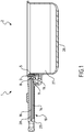
- the handle (1) for cooking vessel (2) or lid as illustrated on the figure 1 is fixedly positioned to a cooking container (2) hereinafter simply called container (2).
- the fixing of the handle (1) on the container (2) or the lid is carried out conventionally, either by a mechanical screw-nut system, or by a system of rivets.
- a container (2) In the case of a container (2), it comprises a bottom (26), a wall (27) which surrounds the bottom (26) and a handle (1).
- This container (2) may be for example a frying pan but may also be a saucepan, a Dutch oven or any other metal container to be heated thermally at the bottom (26).
- the container (2) can be made of aluminum or any other heat conductive material.
- the handle (1) comprises a main body (23). Without limitation this is made of a thermostable material. This body (23) can be made of any other non-heat conducting material.
- the main body (23) is recessed at its center and in the length of the handle (1) to obtain a cavity (28).
- the handle (1) comprises a thermoelectric generator (3).
- This consists of at least one thermoelectric module which may be a Peltier module. In this case, it has two surfaces (5, 8) of contact. A first (5) hot contact surface is brought into contact with a heat source while the second (8) cold contact surface is in contact with a cold source.
- thermoelectric generator (3) comes into contact with the wall (27) of the container (2).
- the handle (1) also comprises a connecting piece (9).
- the second (8) contact surface of the thermoelectric generator (3) is thermally connected to this joining piece (9).
- the handle (1) also comprises a heat sink (10). This heat sink (10) is contained in the cavity (28) of the handle (1).
- this heat sink (10) can be either connected to the junction piece (9), or connected directly to the second (8) contact surface of the thermoelectric generator (3). In both cases the contact has a minimum thermal resistance.
- This heat sink (10) is made of a material for which a phase transition occurs when the material is brought to temperatures ranging from 50 ° C to 70 ° C.
- dissipator (10) thermal according to the invention and visible to the figure 1 it is composed of a solid material (14) melting between 50 ° C and 70 ° C.
- the solid material (14) is a solid paraffin-based mixture.
- the handle (1) may further include a thermal diffuser (16).
- the thermal diffuser (16) extends longitudinally in the handle (1) and more particularly in the heat sink (10).
- the thermal diffuser (16) comprises one or more metal rods which are either connected to the junction piece (9), or connected directly to the second (8) contact surface of the generator (3). thermoelectric. In both cases the contact has a minimum thermal resistance.
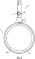
- the handle (1) may also comprise an electronic device (17), as visible in FIG. figure 2 , and connected to the thermoelectric generator (3).
- This electronic device (17) can be an electronic display (18) or an electronic sensor (19).
- This electronic sensor (19) may be for example and without limitation a temperature sensor.
- thermoelectric generator (3) When heating the container (2), it will gradually heat up.
- the wall (27) against which is in contact the first (5) contact surface of the thermoelectric generator (3) also rises in temperature.
- This wall will constitute the hot source for the thermoelectric generator (3).
- the heat sink (10) consists of a material solid whose melting point is between 50 ° C and 70 ° C, it is this solid material (14) which is used as a cold source of the thermoelectric generator (3) and more particularly the latent energy of phase change of this solid material (14) which is stored in the cavity (28) near the thermoelectric generator (3).
- This solid material (14), solid paraffin type will in turn yield this latent energy to the environment during a period of non-use of the product, which is not a problem given the cycles of use of domestic products .
- thermoelectric generator (3) During the heating of the container (2), a flow is established through the thermoelectric generator (3), from the hot source (the wall (27) of the container (2)) to the cold source consisting of the solid material ( 14) and optionally the diffuser (16) thermal.
- the temperature of the solid material (14) will gradually rise from ambient temperature to its melting temperature (about 50 ° C).
- the solid material (14) will gradually melt, remaining at a temperature of about 50 ° C, thus allowing the thermal flow through the thermoelectric generator (3) to remain constant, and the same goes for the production electric.
- the temperature of the handle (1) remains relatively cold compared to a conventional handle. After a time that depends on the amount of solid material (14) and the power of the heat source, the solid body (14) will be completely melted, and the temperature of the handle (1) will start again. raise up to find a thermal equilibrium with the ambient temperature.
- the thermal diffusers (16) are intended to facilitate the heat transfer from the hot source to the cold source but also to optimally distribute heat throughout the solid material (14).
- a handle (1) containing 40 cm3 of solid material (14) type paraffin allows stable operation of the thermoelectric generator (3) for 85 minutes, the maximum recoverable power being 20mW at 2.5V, while the outside temperature close to the handle (1) remains at 66 ° C.
Landscapes
- Engineering & Computer Science (AREA)
- Food Science & Technology (AREA)
- Chemical & Material Sciences (AREA)
- Inorganic Chemistry (AREA)
- Cookers (AREA)
- Frying-Pans Or Fryers (AREA)
Description
- L'invention se situe dans le domaine des poignées pour des récipients de cuisson (appelés également récipients) ou pour des couvercles de récipients de cuisson, appelés simplement couvercles. L'invention concerne plus particulièrement des poignées intégrant des dispositifs de fourniture d'électricité dans le but d'alimenter des fonctions électroniques et qui fonctionnent sur le principe de la conversion thermoélectrique.
- On connait déjà des récipients de cuisson comme par exemple des poêles à frire qui utilisent un dispositif de fourniture d'électricité tel qu'un générateur thermoélectrique pour alimenter un système électronique d'indication de température situé dans la poignée. Lorsque les poêles à frire sont chauffées un flux thermique se crée. Le générateur thermoélectrique utilise ce flux thermique pour produire de l'électricité nécessaire au fonctionnement du système électronique d'indication.
- Le document
CN201015533 divulgue une poêle électronique qui comprend un corps de poêle ainsi qu'une poignée qui est vissée à ce corps de poêle. La poêle comprend également un capteur de température et cette température peut être affichée sur un afficheur intégré dans la poignée. Afin d'alimenter ce capteur et cet afficheur la poêle comprend un générateur thermoélectrique qui génère de l'électricité pour le fonctionnement du capteur et de l'afficheur. Pour produire de l'électricité, ce générateur thermoélectrique comprend deux faces dont la première est positionnée contre le corps de la poêle. Ce positionnement permet d'assurer un échange thermique entre le générateur thermoélectrique et le corps de la poêle. Ce document divulgue également un dissipateur thermique relié à la seconde face du générateur thermoélectrique. Le dissipateur thermique est destiné à favoriser le refroidissement du générateur thermoélectrique et il a la forme d'un radiateur métallique comprenant des ailettes qui s'élèvent verticalement et parallèlement afin de créer un courant d'air de refroidissement par convection par un échange d'air suffisant avec l'air ambiant. Le documentEP2361538 divulgue également une poignée pour un récipient de cuisson comprenant un générateur thermoélectrique, ledit générateur thermoélectrique comportant une première surface de contact reliée thermiquement à un dissipateur thermique. - Cependant pour qu'un tel radiateur soit efficace il faut dimensionner les ailettes de telle sorte que celles-ci aient un encombrement important dans la poignée. Il est alors difficile d'envisager de pouvoir mettre d'autres dispositifs dans cette poignée tel que par exemple le système électronique. Un autre inconvénient rencontré est que le fonctionnement de ce radiateur peut être perturbé voire empêché en fonction du mode d'usage de l'appareil en raison de la circulation de l'air ambiant au voisinage de ce radiateur.
- L'un des aspects que se propose de résoudre la présente invention est de proposer un dissipateur thermique pour une poignée de récipient de cuisson ou de couvercle qui s'affranchisse du refroidissement par convection afin de rendre ce dissipateur thermique plus efficace et moins encombrant pour la poignée.
- Ce but est atteint à l'aide d'une poignée pour récipient de cuisson ou couvercle selon la revendication 1. Selon une caractéristique de l'invention, le dissipateur thermique est composé d'un matériau solide dont la fusion s'effectue entre 50°C et 70°C.
- Selon une caractéristique de l'invention, ce matériau solide est un mélange à base de paraffine solide.
- Selon une caractéristique de l'invention, la poignée comprend un diffuseur thermique.
- Selon une caractéristique de l'invention, le diffuseur thermique comprend une ou plusieurs tiges métalliques.
- Selon une caractéristique de l'invention, la poignée comprend une pièce de jonction positionnée entre le générateur thermoélectrique et le diffuseur thermique.
- Selon une caractéristique de l'invention, le diffuseur thermique est accroché à la pièce de jonction.
- Selon une caractéristique de l'invention, la poignée comprend un dispositif électronique relié au générateur thermoélectrique.
- Selon une caractéristique de l'invention, le dispositif électronique peut être un afficheur électronique ou un capteur électronique.
- On comprendra mieux les buts, aspects et avantages de la présente invention, d'après la description donnée ci-après d'un mode particulier de réalisation de l'invention présenté à titre d'exemple non limitatif, en se référant aux dessins annexés dans lesquels :
- la
figure 1 est une vue en coupe d'un récipient de cuisson comprenant une poignée conforme à l'invention ; - la
figure 2 est une vue de dessus d'un récipient de cuisson comprenant une poignée conforme à l'invention. - La poignée (1) pour récipient (2) de cuisson ou couvercle telle qu'illustrée sur la
figure 1 est positionnée de façon fixe à un récipient (2) de cuisson ci après dénommé simplement récipient (2). - La fixation de la poignée (1) sur le récipient (2) ou le couvercle est effectuée de manière classique, soit par un système mécanique de vis-écrou, soit par un système de rivets.
- Dans le cas d'un récipient (2), celui-ci comprend un fond (26), une paroi (27) qui entoure le fond (26) et une poignée (1). Ce récipient (2) peut être par exemple une poêle à frire mais peut également être une casserole, un faitout ou tout autre contenant métallique destiné à être chauffé thermiquement au niveau du fond (26). Le récipient (2) peut être fait en aluminium ou tout autre matériau conducteur de chaleur.
- La poignée (1) comprend un corps principal (23). De façon non limitative celui-ci est fait dans un matériau thermostable. Ce corps (23) peut être fait dans tout autre matériau non conducteur de chaleur.
- Le corps principal (23) est évidé en son centre et dans la longueur de la poignée (1) afin d'obtenir une cavité (28).
- La poignée (1) comprend un générateur (3) thermoélectrique. Celui-ci est constitué d'au moins un module thermoélectrique qui peut être un module Peltier. Dans ce cas de figure il présente deux surfaces (5, 8) de contact. Une première (5) surface de contact, dite chaude, est mise en contact avec une source de chaleur alors que la seconde (8) surface de contact, dite froide, est quant à elle mise en contact avec une source froide.
- Lorsque la poignée est fixée au récipient (2), la première (5) surface de contact du générateur (3) thermoélectrique vient en contact avec la paroi (27) du récipient (2).
- Toujours en lien avec la
figure 1 , la poignée (1) comprend également une pièce (9) de jonction. La seconde (8) surface de contact du générateur (3) thermoélectrique est reliée thermiquement à cette pièce (9) de jonction. - La poignée (1) comprend également un dissipateur (10) thermique. Ce dissipateur (10) thermique est contenu dans la cavité (28) de la poignée (1).
- Selon deux variantes, ce dissipateur (10) thermique peut être soit relié à la pièce (9) de jonction, soit relié directement à la seconde (8) surface de contact du générateur (3) thermoélectrique. Dans les deux cas le contact a une résistance thermique minimale.
- Dans le second cas, cela signifie que la pièce (9) de jonction a été retirée.
- Ce dissipateur (10) thermique est constitué d'un matériau pour lequel une transition de phase s'opère lorsque le matériau est amené à des températures allant de 50°C à 70°C.
- Dans le mode de réalisation du dissipateur (10) thermique conforme à l'invention et visible à la
figure 1 , celui-ci est composé d'un matériau solide (14) dont la fusion s'effectue entre 50°C et 70°C. - Dans une réalisation particulière du matériau solide (14), celui-ci est un mélange à base de paraffine solide.
- La poignée (1) peut comprendre en plus un diffuseur (16) thermique. Le diffuseur (16) thermique s'étend longitudinalement dans la poignée (1) et plus particulièrement dans le dissipateur (10) thermique.
- Selon une caractéristique de l'invention, le diffuseur (16) thermique comprend une ou plusieurs tiges métalliques qui sont soit reliées à la pièce (9) de jonction, soit reliées directement à la seconde (8) surface de contact du générateur (3) thermoélectrique. Dans les deux cas le contact a une résistance thermique minimale.
- La poignée (1) peut également comprendre un dispositif électronique (17), comme visible à la
figure 2 , et relié au générateur (3) thermoélectrique. Ce dispositif électronique (17) peut être un afficheur (18) électronique ou un capteur électronique (19). - Ce capteur électronique (19) peut être par exemple et de façon non limitative un capteur de température.
- Dans le cas d'un couvercle de récipient, la construction est la même qu'avec l'ustensile (2).
- Lors de la mise en chauffe du récipient (2), celui-ci va progressivement s'échauffer. La paroi (27) contre laquelle est en contact la première (5) surface de contact du générateur (3) thermoélectrique s'élève également en température.
- Cette paroi va constituer la source chaude pour le générateur (3) thermoélectrique.
- Dans le cas où le dissipateur (10) thermique est constitué par un matériau solide dont le point de fusion est compris entre 50°C et 70°C, c'est ce matériau solide (14) qui est utilisé comme source froide du générateur (3) thermoélectrique et plus particulièrement l'énergie latente de changement de phase de ce matériau solide (14) qui est stocké dans la cavité (28) à proximité du générateur (3) thermoélectrique. Ce matériau solide (14), type paraffine solide, devra à son tour céder cette énergie latente à l'environnement lors d'une période de non utilisation du produit, ce qui ne pose pas de problème vu les cycles d'usage des produits domestiques.
- Lors de la chauffe du récipient (2), un flux s'établit au travers du générateur (3) thermoélectrique, allant de la source chaude (la paroi (27) du récipient (2)) vers la source froide constituée du matériau solide (14) et éventuellement du diffuseur (16) thermique. Dans un premier temps, la température du matériau solide (14) va progressivement s'élever de la température ambiante jusqu'à sa température de fusion (environ 50°C). Ensuite, le matériau solide (14) va progressivement fondre, en restant à une température d'environ 50°C, permettant ainsi au flux thermique au travers du générateur (3) thermoélectrique de rester constant, et il en va de même pour la production électrique. Pendant cette période, la température de la poignée (1) reste relativement froide par rapport à une poignée classique. Au bout d'un temps qui dépend de la quantité de matériau solide (14) et de la puissance de la source de chaleur, le corps solide (14) sera complètement fondu, et la température de la poignée (1) recommencera à s'élever jusqu'à trouver un équilibre thermique avec la température ambiante.
- Dans ce cas, les diffuseurs (16) thermiques ont pour but de faciliter le transfert thermique de la source chaude vers la source froide mais également de diffuser de manière optimale la chaleur dans l'ensemble du matériau solide (14).
- On peut également avoir une telle construction mais sans diffuseurs (16) thermiques.
- Dans un cas standard où le récipient (2) est placé sur un foyer dissipant 300W, une poignée (1) contenant 40 cm3 de matériau solide (14) type paraffine permet un fonctionnement stable du générateur (3) thermoélectrique pendant 85 minutes, la puissance maximale récupérable étant de 20mW sous 2,5V, alors que la température extérieure proche de la poignée (1) reste à 66°C.
- On comprendra que diverses modifications et/ou améliorations évidentes pour l'homme du métier peuvent être apportées au mode de réalisation de l'invention décrit dans la présente description sans sortir du cadre de l'invention défini par les revendications annexées.
Claims (9)
- Poignée (1) pour récipient (2) de cuisson ou couvercle qui comprend au moins un générateur (3) thermoélectrique comprenant au moins une première (5) surface de contact reliée thermiquement à un dissipateur (10) thermique, caractérisé en ce que le dissipateur (10) thermique est constitué d'un matériau pour lequel une transition de phase s'opère lorsque le matériau est amené à des températures allant de 50°C à 70°C.
- Poignée (1) pour récipient (2) de cuisson ou couvercle selon la revendication précédente caractérisée en ce que le matériau constituant le dissipateur (10) thermique est un matériau solide dont la fusion s'effectue entre 50°C et 70°C.
- Poignée (1) pour récipient (2) de cuisson ou couvercle selon la revendication précédente caractérisée en ce que le matériau solide est un mélange à base de paraffine solide.
- Poignée (1) pour récipient (2) de cuisson ou couvercle selon les revendications 2 à 3 caractérisée en ce que la poignée (1) comprend un diffuseur (16) thermique.
- Poignée (1) pour récipient (2) de cuisson ou couvercle selon la revendication précédente caractérisée en ce que le diffuseur (16) thermique comprend une ou plusieurs tiges métalliques.
- Poignée (1) pour récipient (2) de cuisson ou couvercle selon les revendications 4 à 5 caractérisée en ce que la poignée (1) comprend une pièce (9) de jonction positionnée entre le générateur (3) thermoélectrique et le diffuseur (16) thermique.
- Poignée (1) pour récipient (2) de cuisson ou couvercle selon la revendication précédente caractérisé en ce que le diffuseur (16) thermique est accroché à la pièce (9) de jonction.
- Poignée (1) pour récipient (2) de cuisson ou couvercle selon l'une des revendications précédentes caractérisée en ce que la poignée (1) comprend un dispositif électronique (17) relié au générateur (3) thermoélectrique.
- Poignée (1) pour récipient (2) de cuisson ou couvercle selon la revendication précédente caractérisée en ce que le dispositif électronique (17) peut être un afficheur (18) électronique ou un capteur électronique (19).
Applications Claiming Priority (2)
| Application Number | Priority Date | Filing Date | Title |
|---|---|---|---|
| FR1459230A FR3026289B1 (fr) | 2014-09-30 | 2014-09-30 | Poignee pour recipient de cuisson comprenant un dissipateur thermique a chaleur latente |
| PCT/FR2015/052577 WO2016051058A1 (fr) | 2014-09-30 | 2015-09-28 | Poignee pour récipient de cuisson comprenant un dissipateur thermique a chaleur latente |
Publications (2)
| Publication Number | Publication Date |
|---|---|
| EP3200663A1 EP3200663A1 (fr) | 2017-08-09 |
| EP3200663B1 true EP3200663B1 (fr) | 2018-05-23 |
Family
ID=51932487
Family Applications (1)
| Application Number | Title | Priority Date | Filing Date |
|---|---|---|---|
| EP15787253.2A Active EP3200663B1 (fr) | 2014-09-30 | 2015-09-28 | Poignee pour récipient de cuisson comprenant un dissipateur thermique a chaleur latente |
Country Status (8)
| Country | Link |
|---|---|
| US (1) | US10193050B2 (fr) |
| EP (1) | EP3200663B1 (fr) |
| JP (1) | JP2017529951A (fr) |
| KR (1) | KR20170062507A (fr) |
| CN (1) | CN107072439B (fr) |
| ES (1) | ES2683233T3 (fr) |
| FR (1) | FR3026289B1 (fr) |
| WO (1) | WO2016051058A1 (fr) |
Families Citing this family (1)
| Publication number | Priority date | Publication date | Assignee | Title |
|---|---|---|---|---|
| US11206943B2 (en) * | 2017-01-26 | 2021-12-28 | John A. Grace | High-temperature liner for cooking devices |
Family Cites Families (11)
| Publication number | Priority date | Publication date | Assignee | Title |
|---|---|---|---|---|
| US6698420B2 (en) * | 1999-10-04 | 2004-03-02 | Michael M. Anthony | Cooking pot apparatus with pot lid having heat exchange means for containing food aromas |
| US6279568B1 (en) * | 1999-10-04 | 2001-08-28 | Michael M. Anthony | Cooking apparatus and method |
| US6570362B1 (en) * | 2000-08-22 | 2003-05-27 | Motorola, Inc. | Portable electronic device with enhanced battery life and cooling |
| US20080008858A1 (en) * | 2006-07-08 | 2008-01-10 | Hong Keith C | Roofing Products Containing Phase Change Materials |
| CN201029753Y (zh) * | 2006-12-20 | 2008-03-05 | 广东威王集团有限公司 | 一种压力锅盖 |
| CN201015533Y (zh) | 2007-04-06 | 2008-02-06 | 明高五金制品(深圳)有限公司 | 半导体制冷片自发电电子锅 |
| US8104163B2 (en) * | 2007-05-22 | 2012-01-31 | Meyer Intellectual Properties Limited | Cookware handle |
| CN101352307B (zh) * | 2008-09-16 | 2010-10-27 | 明高五金制品(深圳)有限公司 | 半导体制冷片温差发电电子测温锅 |
| US20100096116A1 (en) * | 2008-10-17 | 2010-04-22 | Access Business Group International Llc | Heat Diffuser with Silicone Handle |
| FR2961956B1 (fr) * | 2010-06-23 | 2012-08-17 | Commissariat Energie Atomique | Thermogenerateur a materiaux a changement de phase |
| DE102012202196B4 (de) * | 2012-02-14 | 2022-07-21 | Wmf Gmbh | Deckelgriff eines Deckels sowie Deckel |
-
2014
- 2014-09-30 FR FR1459230A patent/FR3026289B1/fr not_active Expired - Fee Related
-
2015
- 2015-09-28 US US15/515,351 patent/US10193050B2/en not_active Expired - Fee Related
- 2015-09-28 ES ES15787253.2T patent/ES2683233T3/es active Active
- 2015-09-28 KR KR1020177011311A patent/KR20170062507A/ko unknown
- 2015-09-28 JP JP2017517332A patent/JP2017529951A/ja active Pending
- 2015-09-28 EP EP15787253.2A patent/EP3200663B1/fr active Active
- 2015-09-28 CN CN201580052103.5A patent/CN107072439B/zh active Active
- 2015-09-28 WO PCT/FR2015/052577 patent/WO2016051058A1/fr active Application Filing
Non-Patent Citations (1)
| Title |
|---|
| None * |
Also Published As
| Publication number | Publication date |
|---|---|
| ES2683233T3 (es) | 2018-09-25 |
| CN107072439B (zh) | 2020-02-18 |
| FR3026289A1 (fr) | 2016-04-01 |
| EP3200663A1 (fr) | 2017-08-09 |
| CN107072439A (zh) | 2017-08-18 |
| KR20170062507A (ko) | 2017-06-07 |
| US10193050B2 (en) | 2019-01-29 |
| JP2017529951A (ja) | 2017-10-12 |
| US20170244020A1 (en) | 2017-08-24 |
| WO2016051058A1 (fr) | 2016-04-07 |
| FR3026289B1 (fr) | 2016-10-07 |
Similar Documents
| Publication | Publication Date | Title |
|---|---|---|
| EP3200662B1 (fr) | Poignée amovible comprenant un générateur thermoélectrique | |
| EP2986191B1 (fr) | Recipient de cuisson comportant un capteur de temperature muni d'un element de fixation | |
| EP0777433B1 (fr) | Appareil de chauffe pour aliments, en particulier pour la realisation de fritures, comportant une contre-cuve | |
| FR2831954A1 (fr) | Procede et appareil de conduction d'energie thermique et conducteur thermique | |
| EP2454919B1 (fr) | Dispositif de chauffe par induction | |
| EP3200663B1 (fr) | Poignee pour récipient de cuisson comprenant un dissipateur thermique a chaleur latente | |
| EP3262477B1 (fr) | Dispositif pour la régulation de température | |
| EP3200664B1 (fr) | Poignée comprenant un générateur thermoélectrique | |
| EP0603969B1 (fr) | Appareil à effet thermique muni d'un indicateur de température | |
| FR2748383A3 (fr) | Recipient de cuisson a parois sous vide | |
| FR3063624B1 (fr) | Dispositif de cuisson en exterieur | |
| FR2882638A3 (fr) | Dispositif de cuisson ayant une structure non-conductrice | |
| WO2000040130A1 (fr) | Friteuse electrique | |
| AU1000502A (en) | Method of conducting thermal energy, thermal conductor, and electrical appliance using the thermal conductor | |
| BE485286A (fr) | ||
| FR2898479A1 (fr) | Cuve d'un barbecue electrique | |
| FR2964027A1 (fr) | Contenant de cuisson pour oeufs | |
| FR2818523A1 (fr) | Ustensile pour la cuisson lente a la vapeur |
Legal Events
| Date | Code | Title | Description |
|---|---|---|---|
| PUAI | Public reference made under article 153(3) epc to a published international application that has entered the european phase |
Free format text: ORIGINAL CODE: 0009012 |
|
| 17P | Request for examination filed |
Effective date: 20170413 |
|
| AK | Designated contracting states |
Kind code of ref document: A1 Designated state(s): AL AT BE BG CH CY CZ DE DK EE ES FI FR GB GR HR HU IE IS IT LI LT LU LV MC MK MT NL NO PL PT RO RS SE SI SK SM TR |
|
| AX | Request for extension of the european patent |
Extension state: BA ME |
|
| DAV | Request for validation of the european patent (deleted) | ||
| DAX | Request for extension of the european patent (deleted) | ||
| GRAP | Despatch of communication of intention to grant a patent |
Free format text: ORIGINAL CODE: EPIDOSNIGR1 |
|
| GRAS | Grant fee paid |
Free format text: ORIGINAL CODE: EPIDOSNIGR3 |
|
| INTG | Intention to grant announced |
Effective date: 20180319 |
|
| GRAA | (expected) grant |
Free format text: ORIGINAL CODE: 0009210 |
|
| AK | Designated contracting states |
Kind code of ref document: B1 Designated state(s): AL AT BE BG CH CY CZ DE DK EE ES FI FR GB GR HR HU IE IS IT LI LT LU LV MC MK MT NL NO PL PT RO RS SE SI SK SM TR |
|
| REG | Reference to a national code |
Ref country code: GB Ref legal event code: FG4D Free format text: NOT ENGLISH |
|
| REG | Reference to a national code |
Ref country code: CH Ref legal event code: EP |
|
| REG | Reference to a national code |
Ref country code: IE Ref legal event code: FG4D Free format text: LANGUAGE OF EP DOCUMENT: FRENCH |
|
| REG | Reference to a national code |
Ref country code: AT Ref legal event code: REF Ref document number: 1000816 Country of ref document: AT Kind code of ref document: T Effective date: 20180615 |
|
| REG | Reference to a national code |
Ref country code: DE Ref legal event code: R096 Ref document number: 602015011506 Country of ref document: DE |
|
| REG | Reference to a national code |
Ref country code: ES Ref legal event code: FG2A Ref document number: 2683233 Country of ref document: ES Kind code of ref document: T3 Effective date: 20180925 |
|
| REG | Reference to a national code |
Ref country code: NL Ref legal event code: MP Effective date: 20180523 |
|
| REG | Reference to a national code |
Ref country code: FR Ref legal event code: PLFP Year of fee payment: 4 |
|
| REG | Reference to a national code |
Ref country code: LT Ref legal event code: MG4D |
|
| PG25 | Lapsed in a contracting state [announced via postgrant information from national office to epo] |
Ref country code: SE Free format text: LAPSE BECAUSE OF FAILURE TO SUBMIT A TRANSLATION OF THE DESCRIPTION OR TO PAY THE FEE WITHIN THE PRESCRIBED TIME-LIMIT Effective date: 20180523 Ref country code: NO Free format text: LAPSE BECAUSE OF FAILURE TO SUBMIT A TRANSLATION OF THE DESCRIPTION OR TO PAY THE FEE WITHIN THE PRESCRIBED TIME-LIMIT Effective date: 20180823 Ref country code: FI Free format text: LAPSE BECAUSE OF FAILURE TO SUBMIT A TRANSLATION OF THE DESCRIPTION OR TO PAY THE FEE WITHIN THE PRESCRIBED TIME-LIMIT Effective date: 20180523 Ref country code: BG Free format text: LAPSE BECAUSE OF FAILURE TO SUBMIT A TRANSLATION OF THE DESCRIPTION OR TO PAY THE FEE WITHIN THE PRESCRIBED TIME-LIMIT Effective date: 20180823 Ref country code: LT Free format text: LAPSE BECAUSE OF FAILURE TO SUBMIT A TRANSLATION OF THE DESCRIPTION OR TO PAY THE FEE WITHIN THE PRESCRIBED TIME-LIMIT Effective date: 20180523 |
|
| PG25 | Lapsed in a contracting state [announced via postgrant information from national office to epo] |
Ref country code: GR Free format text: LAPSE BECAUSE OF FAILURE TO SUBMIT A TRANSLATION OF THE DESCRIPTION OR TO PAY THE FEE WITHIN THE PRESCRIBED TIME-LIMIT Effective date: 20180824 Ref country code: NL Free format text: LAPSE BECAUSE OF FAILURE TO SUBMIT A TRANSLATION OF THE DESCRIPTION OR TO PAY THE FEE WITHIN THE PRESCRIBED TIME-LIMIT Effective date: 20180523 Ref country code: LV Free format text: LAPSE BECAUSE OF FAILURE TO SUBMIT A TRANSLATION OF THE DESCRIPTION OR TO PAY THE FEE WITHIN THE PRESCRIBED TIME-LIMIT Effective date: 20180523 Ref country code: RS Free format text: LAPSE BECAUSE OF FAILURE TO SUBMIT A TRANSLATION OF THE DESCRIPTION OR TO PAY THE FEE WITHIN THE PRESCRIBED TIME-LIMIT Effective date: 20180523 Ref country code: HR Free format text: LAPSE BECAUSE OF FAILURE TO SUBMIT A TRANSLATION OF THE DESCRIPTION OR TO PAY THE FEE WITHIN THE PRESCRIBED TIME-LIMIT Effective date: 20180523 |
|
| REG | Reference to a national code |
Ref country code: AT Ref legal event code: MK05 Ref document number: 1000816 Country of ref document: AT Kind code of ref document: T Effective date: 20180523 |
|
| PG25 | Lapsed in a contracting state [announced via postgrant information from national office to epo] |
Ref country code: CZ Free format text: LAPSE BECAUSE OF FAILURE TO SUBMIT A TRANSLATION OF THE DESCRIPTION OR TO PAY THE FEE WITHIN THE PRESCRIBED TIME-LIMIT Effective date: 20180523 Ref country code: RO Free format text: LAPSE BECAUSE OF FAILURE TO SUBMIT A TRANSLATION OF THE DESCRIPTION OR TO PAY THE FEE WITHIN THE PRESCRIBED TIME-LIMIT Effective date: 20180523 Ref country code: AT Free format text: LAPSE BECAUSE OF FAILURE TO SUBMIT A TRANSLATION OF THE DESCRIPTION OR TO PAY THE FEE WITHIN THE PRESCRIBED TIME-LIMIT Effective date: 20180523 Ref country code: DK Free format text: LAPSE BECAUSE OF FAILURE TO SUBMIT A TRANSLATION OF THE DESCRIPTION OR TO PAY THE FEE WITHIN THE PRESCRIBED TIME-LIMIT Effective date: 20180523 Ref country code: EE Free format text: LAPSE BECAUSE OF FAILURE TO SUBMIT A TRANSLATION OF THE DESCRIPTION OR TO PAY THE FEE WITHIN THE PRESCRIBED TIME-LIMIT Effective date: 20180523 Ref country code: PL Free format text: LAPSE BECAUSE OF FAILURE TO SUBMIT A TRANSLATION OF THE DESCRIPTION OR TO PAY THE FEE WITHIN THE PRESCRIBED TIME-LIMIT Effective date: 20180523 Ref country code: SK Free format text: LAPSE BECAUSE OF FAILURE TO SUBMIT A TRANSLATION OF THE DESCRIPTION OR TO PAY THE FEE WITHIN THE PRESCRIBED TIME-LIMIT Effective date: 20180523 |
|
| REG | Reference to a national code |
Ref country code: DE Ref legal event code: R097 Ref document number: 602015011506 Country of ref document: DE |
|
| PG25 | Lapsed in a contracting state [announced via postgrant information from national office to epo] |
Ref country code: SM Free format text: LAPSE BECAUSE OF FAILURE TO SUBMIT A TRANSLATION OF THE DESCRIPTION OR TO PAY THE FEE WITHIN THE PRESCRIBED TIME-LIMIT Effective date: 20180523 |
|
| PLBE | No opposition filed within time limit |
Free format text: ORIGINAL CODE: 0009261 |
|
| STAA | Information on the status of an ep patent application or granted ep patent |
Free format text: STATUS: NO OPPOSITION FILED WITHIN TIME LIMIT |
|
| PG25 | Lapsed in a contracting state [announced via postgrant information from national office to epo] |
Ref country code: MC Free format text: LAPSE BECAUSE OF FAILURE TO SUBMIT A TRANSLATION OF THE DESCRIPTION OR TO PAY THE FEE WITHIN THE PRESCRIBED TIME-LIMIT Effective date: 20180523 |
|
| REG | Reference to a national code |
Ref country code: CH Ref legal event code: PL |
|
| 26N | No opposition filed |
Effective date: 20190226 |
|
| REG | Reference to a national code |
Ref country code: IE Ref legal event code: MM4A |
|
| PG25 | Lapsed in a contracting state [announced via postgrant information from national office to epo] |
Ref country code: LU Free format text: LAPSE BECAUSE OF NON-PAYMENT OF DUE FEES Effective date: 20180928 |
|
| PG25 | Lapsed in a contracting state [announced via postgrant information from national office to epo] |
Ref country code: IE Free format text: LAPSE BECAUSE OF NON-PAYMENT OF DUE FEES Effective date: 20180928 |
|
| PG25 | Lapsed in a contracting state [announced via postgrant information from national office to epo] |
Ref country code: LI Free format text: LAPSE BECAUSE OF NON-PAYMENT OF DUE FEES Effective date: 20180930 Ref country code: CH Free format text: LAPSE BECAUSE OF NON-PAYMENT OF DUE FEES Effective date: 20180930 |
|
| PG25 | Lapsed in a contracting state [announced via postgrant information from national office to epo] |
Ref country code: AL Free format text: LAPSE BECAUSE OF FAILURE TO SUBMIT A TRANSLATION OF THE DESCRIPTION OR TO PAY THE FEE WITHIN THE PRESCRIBED TIME-LIMIT Effective date: 20180523 |
|
| PG25 | Lapsed in a contracting state [announced via postgrant information from national office to epo] |
Ref country code: MT Free format text: LAPSE BECAUSE OF FAILURE TO SUBMIT A TRANSLATION OF THE DESCRIPTION OR TO PAY THE FEE WITHIN THE PRESCRIBED TIME-LIMIT Effective date: 20180523 |
|
| PG25 | Lapsed in a contracting state [announced via postgrant information from national office to epo] |
Ref country code: TR Free format text: LAPSE BECAUSE OF FAILURE TO SUBMIT A TRANSLATION OF THE DESCRIPTION OR TO PAY THE FEE WITHIN THE PRESCRIBED TIME-LIMIT Effective date: 20180523 |
|
| PG25 | Lapsed in a contracting state [announced via postgrant information from national office to epo] |
Ref country code: PT Free format text: LAPSE BECAUSE OF FAILURE TO SUBMIT A TRANSLATION OF THE DESCRIPTION OR TO PAY THE FEE WITHIN THE PRESCRIBED TIME-LIMIT Effective date: 20180523 |
|
| PG25 | Lapsed in a contracting state [announced via postgrant information from national office to epo] |
Ref country code: CY Free format text: LAPSE BECAUSE OF FAILURE TO SUBMIT A TRANSLATION OF THE DESCRIPTION OR TO PAY THE FEE WITHIN THE PRESCRIBED TIME-LIMIT Effective date: 20180523 Ref country code: HU Free format text: LAPSE BECAUSE OF FAILURE TO SUBMIT A TRANSLATION OF THE DESCRIPTION OR TO PAY THE FEE WITHIN THE PRESCRIBED TIME-LIMIT; INVALID AB INITIO Effective date: 20150928 Ref country code: MK Free format text: LAPSE BECAUSE OF NON-PAYMENT OF DUE FEES Effective date: 20180523 |
|
| PG25 | Lapsed in a contracting state [announced via postgrant information from national office to epo] |
Ref country code: IS Free format text: LAPSE BECAUSE OF FAILURE TO SUBMIT A TRANSLATION OF THE DESCRIPTION OR TO PAY THE FEE WITHIN THE PRESCRIBED TIME-LIMIT Effective date: 20180923 |
|
| PG25 | Lapsed in a contracting state [announced via postgrant information from national office to epo] |
Ref country code: SI Free format text: LAPSE BECAUSE OF NON-PAYMENT OF DUE FEES Effective date: 20180928 |
|
| REG | Reference to a national code |
Ref country code: FR Ref legal event code: PLFP Year of fee payment: 8 |
|
| PGFP | Annual fee paid to national office [announced via postgrant information from national office to epo] |
Ref country code: IT Payment date: 20230911 Year of fee payment: 9 Ref country code: GB Payment date: 20230920 Year of fee payment: 9 |
|
| PGFP | Annual fee paid to national office [announced via postgrant information from national office to epo] |
Ref country code: FR Payment date: 20230927 Year of fee payment: 9 Ref country code: DE Payment date: 20230911 Year of fee payment: 9 Ref country code: BE Payment date: 20230914 Year of fee payment: 9 |
|
| PGFP | Annual fee paid to national office [announced via postgrant information from national office to epo] |
Ref country code: ES Payment date: 20231006 Year of fee payment: 9 |