EP3200428B1 - Computer-implemented method for implementing a v2x-application - Google Patents
Computer-implemented method for implementing a v2x-application Download PDFInfo
- Publication number
- EP3200428B1 EP3200428B1 EP16152681.9A EP16152681A EP3200428B1 EP 3200428 B1 EP3200428 B1 EP 3200428B1 EP 16152681 A EP16152681 A EP 16152681A EP 3200428 B1 EP3200428 B1 EP 3200428B1
- Authority
- EP
- European Patent Office
- Prior art keywords
- sensor
- data
- message
- object list
- computer
- Prior art date
- Legal status (The legal status is an assumption and is not a legal conclusion. Google has not performed a legal analysis and makes no representation as to the accuracy of the status listed.)
- Active
Links
Images

Classifications
-
- H—ELECTRICITY
- H04—ELECTRIC COMMUNICATION TECHNIQUE
- H04L—TRANSMISSION OF DIGITAL INFORMATION, e.g. TELEGRAPHIC COMMUNICATION
- H04L67/00—Network arrangements or protocols for supporting network services or applications
- H04L67/01—Protocols
- H04L67/12—Protocols specially adapted for proprietary or special-purpose networking environments, e.g. medical networks, sensor networks, networks in vehicles or remote metering networks
-
- H—ELECTRICITY
- H04—ELECTRIC COMMUNICATION TECHNIQUE
- H04L—TRANSMISSION OF DIGITAL INFORMATION, e.g. TELEGRAPHIC COMMUNICATION
- H04L67/00—Network arrangements or protocols for supporting network services or applications
- H04L67/34—Network arrangements or protocols for supporting network services or applications involving the movement of software or configuration parameters
-
- H—ELECTRICITY
- H04—ELECTRIC COMMUNICATION TECHNIQUE
- H04L—TRANSMISSION OF DIGITAL INFORMATION, e.g. TELEGRAPHIC COMMUNICATION
- H04L67/00—Network arrangements or protocols for supporting network services or applications
- H04L67/50—Network services
- H04L67/51—Discovery or management thereof, e.g. service location protocol [SLP] or web services
-
- H—ELECTRICITY
- H04—ELECTRIC COMMUNICATION TECHNIQUE
- H04W—WIRELESS COMMUNICATION NETWORKS
- H04W76/00—Connection management
- H04W76/40—Connection management for selective distribution or broadcast
-
- H—ELECTRICITY
- H04—ELECTRIC COMMUNICATION TECHNIQUE
- H04W—WIRELESS COMMUNICATION NETWORKS
- H04W84/00—Network topologies
- H04W84/005—Moving wireless networks
Definitions
- the invention relates to a computer-implemented method for implementing a V2X application on a target hardware with a radio adapter, the V2X application being modeled with a graphical modeling environment in the form of a block diagram.
- the invention further relates to various blocks for use in a graphical modeling environment with which a V2X application can be modeled and implemented.
- control-related functionality is not to be understood narrowly in the system-theoretical sense, it means any targeted influence on a technical process associated with the control device. This can also only be the processing and / or fusion of sensor data, for example of environmental sensors.
- V-model The associated development goes through various phases, which are part of the so-called V-model.
- desired control-related functionality is initially mapped abstractly in the context of offline simulations - no connection to the real process, no real-time requirement - using a mathematical model, usually with block diagrams, both the control and control-related aspect and the technical-physical process to be influenced can be mathematically simulated and simulated using numerical methods.
- the control-related functionality is converted into program code and implemented on target hardware that usually differs considerably from the series control unit that will be used later.
- the target hardware is usually more powerful than series control units, so that when testing the control functionality to be implemented it is ensured that the hardware is not a limiting factor in the design.
- the target hardware instrumented in this way is tested in any case in connection with the technical process to be influenced.
- the target hardware does not necessarily have to differ from the hardware on which the graphic modeling environment is operated and / or with which the translation into an executable V2X program takes place; in this case the transfer to the target hardware is very short, the program only has to be loaded and executed.
- the target hardware can also be a PC, including the PC on which the modeling environment is executed and / or the model / block diagram is translated into an executable program.
- the series target hardware i.e. the series control device
- the control algorithm to be implemented for this target hardware is generated, the series control device then not being tested in connection with the real physical process, but with a simulated process environment as part of a hardware in-the-loop test (HIL test).
- HIL test hardware in-the-loop test
- the target hardware is tested in the form of the series control unit in a real physical process, in the present case in the motor vehicle, with adjustments being made in the parameterization if necessary.
- the block diagram is translated into a V2X program that can be executed on the target hardware, then it can also be such a program that is interpreted on the target hardware for execution; even then it is an executable V2X program.
- the vehicles can be road vehicles, for example, so that Car2X applications can be used in this case.
- the environment can also consist of other objects and means of communication, e.g. B. also backend servers in the cloud.
- a system that uses such communication is also known as an intelligent transport system (ITS).
- ITS intelligent transport system
- the road users participating in the ITS regularly send V2X messages with their telematics data in order to inform the other road users about their status.
- the status includes, for example, the location, the speed and the direction of movement of the road user.
- Such messages are also referred to as cooperative awareness messages (CAM).
- CAM cooperative awareness messages
- a road user who receives these CAMs can then keep a list of all road users from whom he has received a status.
- Such a list is also known as a local dynamic map (LDM). Since not all road users send out CAMs, in most cases an LDM will not contain all road users. Due to this incomplete database, road users cannot optimally use all the advantages of the ITS.
- LDM local dynamic map
- WO 2015/144887 A2 describes a computer-implemented method for implementing a V2X application on a target hardware with a radio adapter, the V2X application being modeled with a graphical modeling environment in the form of a block diagram.
- the object of the invention is to provide a method that enables a more complete database to be obtained.
- the subject matter is a computer-implemented method for implementing a V2X application on target hardware with a radio adapter, the V2X application being modeled with a graphical modeling environment in the form of a block diagram which comprises an LDM object list in which received telematics data from surrounding objects are recorded , wherein telematics data of surrounding objects determined in a sensor object list are recorded, the block diagram comprising a telematics data comparison block which determines by comparison of the LDM object list with the sensor object list difference environmental objects which are only recorded in the sensor object list, and wherein For at least one of the differential environment objects, a substitute V2X message is created in the block diagram with the telematics data of this differential environment object, the block diagram being translated into a V2X program executable on the target hardware and the V2X program for the target hardware is transferred and executed there, the substitution V2X message being sent by the target hardware via the radio adapter.
- Telematics data is understood here to mean telematics data which were received as such by the target hardware and which were therefore not reconstructed from other data by the target hardware.
- Telematics data received can originate, for example, from V2X messages from other road users.
- the received messages assign certain properties to certain objects. These can be time-independent properties such as the dimensions, but also time-dependent properties such as location or speed. For time-dependent properties, the messages can contain time stamps or a time stamp is assigned to the messages on receipt.
- Determined telematics data is understood here to mean telematics data that have been reconstructed from the target hardware from other data.
- the target hardware can be connected to a sensor.
- Objects and some properties such as location or speed of the objects can then be determined from the sensor data.
- a sensor can be, for example, a radar sensor, an ultrasound sensor, a video sensor or a lidar sensor.
- the objects in the LDM object list and the sensor object list can be other road users, for example. So cars, trucks, motorcycles, bicycles, pedestrians, wheelchair users, strollers or similar.
- the properties of the objects in the object lists can be compared.
- location, speed, direction of movement and time stamp of the properties can be compared and it can be determined from this whether two objects in the two lists describe the same object.
- the target hardware can itself comprise the radio adapter in an integrated hardware solution, but the target hardware can also be connected to a radio adapter via a separately implemented hardware interface. If we are talking here that the block diagram created with the graphic modeling environment is translated into a V2X program that can be executed on the target hardware, then this program can be a program that can be executed on a processor / microcontroller, but it can also be is a hardware description with which a circuit structure is given the desired functionality by "hard wiring".
- the block diagram is translated into a V2X program that can be executed on the target hardware, then it can also be such a program that is interpreted on the target hardware for execution; even then it is an executable V2X program.
- the telematics data of road users who do not send V2X messages themselves are disseminated via substitute V2X messages that appear to the recipients as normal V2X messages.
- the distribution takes place via road users or traffic infrastructure that can send V2X messages and have the functionality shown above.
- the number of road users whose telematics data is distributed via V2X messages is thereby increased and the overall performance of the ITS is improved since more is known about the road users.
- the proxy V2X message is created to appear to the recipients as if it had been sent by the differential environment object itself.
- a message is compiled with the data of the difference environment object.
- the data relevant for the V2X applications such as speed, direction of movement, position and vehicle class, are adapted accordingly to the difference surrounding object.
- the position of the difference environment object can be specified instead of your own position.
- the use another signature key for generating the electronic signature of the message is purely optional.
- An advantage of the embodiment is that the recipients of the substitution V2X message do not incorrectly assign the telematics data contained to the sender of the substitution V2X message.
- the signature is typically only used for an integrity check and therefore the same signature key as for your own V2X messages can be used for the substitution message.
- the block diagram includes a substitution message block that creates the substitution V2X message, the substitution V2X message containing at least the telematics data of the differential environment object.
- An advantage of the further development is that the formal requirements for the creation of the substitute V2X message are decoupled from the comparison of the object lists. If the formal requirements change, e.g. because the V2X program is to be used in another ITS with different formal requirements, only the substitute message block has to be exchanged. The telematics data comparison block, however, can be left unchanged.
- the target hardware is connected to at least one sensor.
- the target hardware is therefore able to receive data from the sensor.
- This data can be raw data, i.e. the direct measured values of the sensor, as well as processed data, i.e. information about objects recognized by the sensor and their properties.
- a sensor can also be a simulated sensor. In this case, a real measurement is not carried out by a sensor, but a simulator provides data that that of a real sensor same. This can be useful, for example, when testing the modeled program if the target hardware is to be checked for correct function using a simulator.
- An advantage of the configuration is that the target hardware can receive current data from the sensor and can thus update the telematics data in the sensor object list. In this way, current data are available in the sensor object list for comparison with the telematics data of the LDM object list.
- the telematics data are determined by means of at least one radar, lidar, ultrasound and / or video sensor and entered into the sensor object list by the V2X program.
- Data from sensors that can detect the location, speed, acceleration, type of object or a combination of these properties of objects are advantageous. This data can then be stored in the sensor object list and processed from there.
- the block diagram includes a data fusion block that compares the telematics data of different sensors with one another, and only consistent telematics data are entered into the sensor object list by the V2X program.
- Consistent telematics data are understood here to mean data in which the differences in the data from several sensors for the same property of the same object lie below a predetermined threshold value.
- a threshold value can be, for example, the measurement inaccuracy of the sensor or a multiple thereof.
- An advantage of the further development is that the reliability of the telematics data in the sensor object list can be increased.
- V2X messages with telematics data from other road users are received via a radio receiver, in particular from Cooperative Awareness Messages (CAM), the telematics data are transferred to the V2X program and entered into the LDM object list by the V2X program.
- CAM Cooperative Awareness Messages
- the V2X messages can be received via the same radio receiver via which the substitute V2X message is sent, but an additional radio receiver for receiving the V2X messages can also be connected to the target hardware.
- the V2X messages can be transferred unchanged from the radio receiver to the V2X program, but it is also possible that only the telematics data are transferred to the V2X program.
- the reception of telematics data from other road users can also be simulated. In this case, the simulated V2X messages or directly the simulated telematics data can be transmitted to the V2X program.
- An advantage of the embodiment is that the telematics data in the LDM object list are updated by the received telematics data from the V2X messages.
- the V2X messages can be assigned to the sending object and its telematics data can be updated in the LDM object list. In this way, current values are available for comparison with the telematics data from the sensor object list.
- the telematics data of the environment objects are stored in the LDM object list as absolute telematics data.
- Absolute telematics data are understood here to mean telematics data that relate to a frame of reference that does not depend on the object. The data are therefore given in relation to an external frame of reference.
- E.g. locations can be specified in relation to the GPS grid and speeds in relation to the resting surface of the earth.
- An advantage of the embodiment is that the absolute telematics data can be processed more easily by the uniform reference frame, since the reference frame does not have to be known for every object.
- the telematics data of the environmental objects are stored in the sensor object list as relative telematics data relative to the sensor's own movement data, and absolute telematics data of the surroundings objects are determined from the relative telematics data of the environment objects in the sensor object list and the sensor's own movement data.
- Position, speed and / or acceleration of the sensor are viewed here, for example, under self-movement data.
- data from sensors is recorded relative to the sensor.
- the telematics data In order to be able to compare the relative telematics data of the sensor object list with the absolute telematics data of the LDM object list, the telematics data must be converted into a uniform frame of reference. By simply adding the own movement data and the sensor data, the relative telematics data can easily be converted into absolute telematics data and then compared with the absolute telematics data of the LDM object list.
- the own movement data can also come from a simulation of the own movement of the sensor. This is advantageous, for example, for test purposes.
- the sensor's own movement data are determined at least in part via a global navigation satellite system.
- GNSS global navigation satellite systems
- GPS global navigation satellite systems
- GLONASS Globalstar Satellite System
- GALILEO Beidou
- the position and speed of the Receiver of the satellite signals can be determined.
- a GNSS is therefore very suitable for determining the sensor's own movement data.
- further sensors can be used to determine the own movement data.
- wheel sensors can measure the speed and / or acceleration of the vehicle.
- Inertia sensors can also be used to measure accelerations.
- the substitution V2X message is created as a cooperative awareness message (CAM).
- CAM cooperative awareness message
- An advantage of the configuration is that the shape of a CAM is known and standardized. This enables the recipient of the substitute V2X message to treat it like a normal CAM. The receivers therefore do not have to be specially prepared to receive the substitute V2X message, but only have to be able to process the known CAMs. However, the substitution V2X message does not contain the telematics data of the sending road user like a normal CAM, but the telematics data of the differential environment object. In an alternative embodiment, a Basic Safety Message (BSM) can also be used instead of the CAM.
- BSM Basic Safety Message
- the target hardware is housed in a vehicle.
- a vehicle is typically in motion and can thus compare telematics data determined at different locations and telematics data received at different locations.
- the target hardware is accommodated in a stationary traffic infrastructure.
- the stationary traffic infrastructure can permanently monitor a special area, for example an intersection area.
- the traffic infrastructure can transmit telematics data to remote recipients so that they are informed about the objects in this area before they reach the area.
- a partial aspect also relates to a telematics data comparison block for implementing a V2X application with a graphical modeling environment in the form of a block diagram, the received telematics data from surrounding objects being recorded in an LDM object list, the determined telematics data from surrounding objects being recorded in a sensor object list, whereby the telematics data comparison block is determined by comparing the LDM object list with the sensor object list, difference environmental objects that are only recorded in the sensor object list.
- the telematics data comparison block can, for example, compare the properties of the objects, such as location or speed, and start from the same object if the differences in the properties lie below a predetermined threshold value. In other words, the telematics data comparison block can start from the same object if the properties of the objects are consistent.
- a partial aspect also relates to a substitution message block for implementing a V2X application with a graphical modeling environment in the form of a block diagram, the V2X substitution message block created at least one substitute V2X message with telematics data of a differential environment object.
- the substitution message block can be used to simplify the creation of the substitution V2X message within the modeling environment.
- the substitution message block receives the telematics data of the differential environment object and uses it to create the substitution V2X message, i.e. H. it ensures that the protocol requirements for a V2X message are met. For example, he can enter a sender or digitally sign the substitute V2X message.
- the substitution V2X message is created by the substitution message block in such a way that the substitution V2X message appears to the recipient as if it had been sent out by the difference environment object itself.
- the proxy V2X message appears to the recipient as if it had been sent by the differential environment object itself, for example, by entering a different sender in the proxy V2X message than the one sent by the target hardware V2X messages. Also, the proxy V2X message can be signed with a different signature key than other V2X messages sent by the target hardware.
- An advantage of the embodiment is that the recipients of the representative V2X message do not incorrectly assign the telematics data contained to the sender of the representative V2X message.
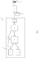
- Fig. 1 the sequence of the proposed computer-implemented method 1 for implementing a V2X application on a target hardware 2 with a radio adapter 3 is shown schematically, the V2X application being modeled with a graphical modeling environment 4 in the form of a block diagram 5.
- the V2X application modeled as a block diagram 5 accesses an LDM object list 6 and the received telematics data of surrounding objects contained therein.
- the V2X application also accesses a sensor object list 7 and the determined telematics data contained in it from surrounding objects.
- a telematics data comparison block 8 contained in block diagram 5 determines, by comparing the telematics data contained in the lists, differential environment objects which are only recorded in the sensor object list.
- a representative V2X message 9 is created in block diagram 5 for at least one differential environment object.
- Block diagram 5 and the V2X application modeled with it are first translated into a V2X program 10 executable on target hardware 2, and V2X program 10 is then transferred to target hardware 2 and executed there. This takes place overall via intermediate stages not shown in detail here: the block diagram 5 is analyzed and first translated into program code, the program code then being compiled so that the executable V2X program 10 results.
- the V2X program 10 executed on the target hardware 2 thus implements the functionality of the V2X application 10 previously modeled using the graphical modeling environment 4 in the form of the block diagram 5.
- the created substitution V2X message 9 is sent via the radio adapter 3 on the target hardware 2 during the execution of the V2X program 10.
- the radio adapter 3 represents the technical medium with which either with other vehicles or with other, fixed Communication partners is communicated, such as B. light signals, traffic jam stations, etc.
- the target hardware builds an ad hoc network with the other communication partners within radio range, which is naturally highly variable due to the constantly changing communication partners.
- the implementation of a V2X application on the target hardware 2 is facilitated by the use of a telematics data comparison block 8, with which the block diagram 5 is created, at least in part.
- the telematics data comparison block 8 contains an elementary object comparison functionality with which telematics data can easily be compared. Because the telematics data comparison block 8 has the required functionality for comparing telematics data from the two object lists 6, 7, it is no longer necessary to model this functionality in detail with elementary operations of the modeling environment 4.
- the object lists 6, 7 contain a multitude of properties as telematics data for each object. These properties can be, for example, movement data such as location, speed or direction of movement.
- the telematics data comparison block compares the properties of the objects with one another. If several properties of an object from the sensor object list and an object from the LDM object list are essentially the same, then they are regarded as the same object. In order for two objects to be considered the same object, not all properties have to be essentially the same, but it is advantageous if several properties have to be essentially the same in order for the objects to be considered the same object. Two properties are considered substantially the same if the difference in property values is below a predetermined threshold.
- the threshold values for deciding whether two properties are essentially the same can be set for each property during modeling in the modeling environment 4. Is too it is possible to make the threshold dependent on external conditions. So z. B. Weather conditions worsen measurements and justify a larger threshold. If there is no property value for a property in a list for an object, this property is not used for the comparison of the object. If the telematics data comparison block 8 does not find an essentially identical object in the LDM object list for an object from the sensor object list 7, it outputs this object as a difference environment object.
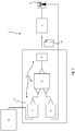
- Block diagram 5 contains a substitution message block 11.
- Substitution message block 11 receives the telematics data of a differential environment object from telematics data comparison block 8 and creates a substitution V2X message 9 from the telematics data.
- the implementation of a V2X application on the target hardware 2 is facilitated by the use of a substitute message block 11, with which the block diagram 5 is created, at least in part.
- the substitution message block 11 contains the functionality required to be able to create a substitution V2X message 9 from the telematics data of a differential environment object.
- the formal requirements for V2X messages and corresponding signature keys are stored in the representation message block 11. Because the representation message block 11 has this functionality, it is no longer necessary to model this functionality in detail with elementary operations of the modeling environment 4.
- a first sensor 12 is communicatively coupled to the sensor object list 7.
- the communicative connection is shown here, it is understood that the function of the block diagram 5 shown on the target hardware 2 is executed and the target hardware 2 establishes the communicative connection to the sensor 12.
- This first sensor 12 can be, for example, a radar sensor, an ultrasound sensor, a video sensor or a lidar sensor.
- the first sensor scans its surroundings. Objects and their properties in the surroundings of the first sensor 12 can be identified by means of the sensor data. Which properties can be identified depends on the sensor used.
- the identified objects and their properties are then entered by the V2X program 10 in the sensor object list 7.
- the radio adapter 3 is communicatively connected to the LDM object list 6.
- the radio adapter 3 receives V2X messages from other road users or from the traffic infrastructure.
- the telematics data contained in the received V2X messages are stored by the V2X program 10 in the LDM object list 6.
- the V2X program 10 can update the telematics data in the sensor object list via the communicative connections to the sensor. By receiving V2X messages from other road users, the V2X program 10 can update the telematics data in the LDM object list.
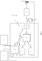
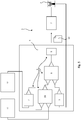
- FIG 5 Another embodiment of method 1 is shown. Below are just the differences from that Figure 3 explained.
- the telematics data transmitted from the sensor 12 into the sensor object list 7 are stored in the sensor object list 7 as relative data relative to the sensor.
- the received telematics data in the LDM object list 6, are stored as absolute data, ie relative to the earth's surface.
- the sensor's own movement data 15 are loaded by the V2X program 10.
- the self-movement data 15 indicate the position, speed, acceleration and / or orientation of the sensor relative to the earth's surface.
- the V2X program 10 can calculate absolute sensor telematics data 16 by suitably linking the relative telematics data from the sensor object list 7 with the self-movement data 15 of the sensor.
- the absolute sensor telematics data 16 can then be compared with the absolute telematics data from the LDM object list 6 by the telematics data comparison block 8.
Description
Die Erfindung betrifft ein computerimplementiertes Verfahren zur Implementierung einer V2X-Anwendung auf einer Zielhardware mit einem Funkadapter, wobei die V2X-Anwendung mit einer grafischen Modellierungsumgebung in Form eines Blockschaltbildes modelliert wird. Die Erfindung betrifft ferner verschiedene Blöcke zur Verwendung in einer grafischen Modellierungsumgebung, mit denen eine V2X-Anwendung modelliert und implementiert werden kann.The invention relates to a computer-implemented method for implementing a V2X application on a target hardware with a radio adapter, the V2X application being modeled with a graphical modeling environment in the form of a block diagram. The invention further relates to various blocks for use in a graphical modeling environment with which a V2X application can be modeled and implemented.
Die Erfindung entstammt dem Umfeld der Steuergeräteentwicklung, sie betrifft hier weniger die hardwaremäßige Entwicklung eines Steuergeräts, sondern vielmehr die Entwicklung und den Test einer im weitesten Sinne regelungstechnischen Funktionalität auf einem Steuergerät. Der Begriff "regelungstechnische Funktionalität" ist nicht eng im systemtheoretischen Sinne zu verstehen, gemeint ist jegliche gezielte Einflussnahme auf einen mit dem Steuergerät verbundenen technischen Prozess. Das kann auch lediglich die Verarbeitung und/oder Fusion von Sensordaten sein, beispielsweise von Umgebungssensoren.The invention originates from the field of control unit development, it relates less to the hardware development of a control unit, but rather to the development and testing of a control function in the broadest sense on a control unit. The term "control-related functionality" is not to be understood narrowly in the system-theoretical sense, it means any targeted influence on a technical process associated with the control device. This can also only be the processing and / or fusion of sensor data, for example of environmental sensors.
Die damit verbundene Entwicklung durchläuft verschiedene Phasen, die Teil des sogenannten V-Modells sind. Üblicherweise wird die gewünschte regelungstechnische Funktionalität zunächst abstrakt im Rahmen von Offline-Simulationen - keine Verbindung zum realen Prozess, keine Echtzeitanforderung - durch ein mathematisches Modell abgebildet, wobei üblicherweise mit Blockschaltbildern sowohl der regelungs- und steuerungstechnische Aspekt wie auch der zu beeinflussende technisch-physikalische Prozess mathematisch nachgebildet und mit Hilfe von numerischen Verfahren simuliert werden.The associated development goes through various phases, which are part of the so-called V-model. Usually, the desired control-related functionality is initially mapped abstractly in the context of offline simulations - no connection to the real process, no real-time requirement - using a mathematical model, usually with block diagrams, both the control and control-related aspect and the technical-physical process to be influenced can be mathematically simulated and simulated using numerical methods.
In einem weiteren Schritt wird die regelungstechnische Funktionalität in Programmcode umgesetzt und auf einer Zielhardware implementiert, die sich von dem später zum Einsatz kommenden Seriensteuergerät meist erheblich unterscheidet. Die Zielhardware ist üblicherweise leistungsfähiger als Seriensteuergeräte, so dass beim Test der zu implementierenden regelungstechnischen Funktionalität jedenfalls sichergestellt ist, dass die Hardware kein limitierender Faktor im Aufbau ist. Die so instrumentierte Zielhardware wird jedenfalls im Zusammenhang mit dem zu beeinflussenden technischen Prozess getestet. Die Zielhardware muss sich nicht zwingend von der Hardware unterscheiden, auf der die grafische Modellierungsumgebung betrieben wird und/oder mit der die Übersetzung in ein ausführbares V2X-Programm erfolgt; in diesem Fall ist die Übertragung auf die Zielhardware dann denkbar kurz, das Programm muss lediglich geladen und ausgeführt werden. Die Zielhardware kann also auch ein PC sein, auch der PC, auf dem die Modellierungsumgebung ausgeführt und/oder die Übersetzung des Modells/Blockschaltbildes in ein ausführbares Programm erfolgt.In a further step, the control-related functionality is converted into program code and implemented on target hardware that usually differs considerably from the series control unit that will be used later. The target hardware is usually more powerful than series control units, so that when testing the control functionality to be implemented it is ensured that the hardware is not a limiting factor in the design. The target hardware instrumented in this way is tested in any case in connection with the technical process to be influenced. The target hardware does not necessarily have to differ from the hardware on which the graphic modeling environment is operated and / or with which the translation into an executable V2X program takes place; in this case the transfer to the target hardware is very short, the program only has to be loaded and executed. The target hardware can also be a PC, including the PC on which the modeling environment is executed and / or the model / block diagram is translated into an executable program.
Sobald die Serien-Zielhardware, also das Seriensteuergerät, zur Verfügung steht, wird der zu implementierende Regelungsalgorithmus für diese Zielhardware erzeugt, wobei das Seriensteuergerät dann zunächst nicht im Zusammenhang mit dem echten physikalischen Prozess getestet wird, sondern mit einer simulierten Prozessumgebung im Rahmen eines Hardware-in-the-Loop-Test (HIL-Test). Nach erfolgreich absolviertem HIL-Test wird die Zielhardware in Form des Seriensteuergeräts im echten physikalischen Prozess, vorliegend also im Kraftfahrzeug, getestet, wobei hier ggf. noch Abstimmungen in der Parametrierung erfolgen.As soon as the series target hardware, i.e. the series control device, is available, the control algorithm to be implemented for this target hardware is generated, the series control device then not being tested in connection with the real physical process, but with a simulated process environment as part of a hardware in-the-loop test (HIL test). After successfully completing the HIL test, the target hardware is tested in the form of the series control unit in a real physical process, in the present case in the motor vehicle, with adjustments being made in the parameterization if necessary.
Wichtig für sämtliche Entwicklungsschritte ist, dass der aus dem Blockschaltbild bekannte abstrakte Regelungsvorgang - im zuvor ausgeführten Sinne eine regelungstechnische Funktionalität, die auch in einer Sensordatenauswertung oder Datenfusion bestehen kann - nicht mehr manuell in Programmcode übersetzt wird, sondern dass diese Übertragung durch einen automatisierten Codegenerierungsprozess aus dem Blockschaltbild heraus erfolgt. So werden die fehlerträchtige manuelle Übertragung vermieden und schnelle Testzyklen mit variierender regelungstechnischer Funktionalität ermöglicht. Die Funktionalität der Blockschaltbilder bzw. der Blöcke der Blockschaltbilder selbst kann ganz unterschiedlich implementiert sein. Es ist möglich, dass die Funktionalität eines Blockschaltbildes intern mit weiteren Blockschaltbildern und Blöcken elementarerer Funktionalität realisiert ist - in Sub- und Subsub-Blockschaltbildern und Blöcken usw. -, es kann aber auch sein, dass die Funktionalität eines Blockschaltbildes selbst in einer höheren Programmier- bzw. Beschreibungssprache hinterlegt ist; darauf kommt es im Einzelnen nicht an.It is important for all development steps that the abstract control process known from the block diagram - in the previously described sense a control functionality that can also consist of sensor data evaluation or data fusion - is no longer translated manually into program code, but that this transmission is carried out by an automated code generation process the Block diagram is done. This avoids the error-prone manual transmission and enables fast test cycles with varying control functions. The functionality of the block diagrams or the blocks of the block diagrams themselves can be implemented in very different ways. It is possible that the functionality of a block diagram is implemented internally with further block diagrams and blocks of elementary functionality - in sub- and subsub block diagrams and blocks etc. - but it can also be the case that the functionality of a block diagram can be implemented even in a higher programming or description language is stored; that is not what matters in detail.
Mit den heute gängigen grafischen Modellierungs- und Simulationsumgebungen lassen sich durch Verwendung der zur Verfügung stehenden Elementaroperationen (Grundrechenarten, Differential- und Integraloperationen, Bitbeeinflussung, Look-Up-Tables etc.) praktisch beliebige Funktionalitäten nachbilden, wie beispielsweise auch die Buskommunikation zwischen Steuergeräten oder eine Sensordatenauswertung und -fusion. Auch kann in Blöcken Programmcode hinterlegt werden, beispielsweise C/C++ oder C#-Code. Beispiele für Entwicklungsumgebungen, die auf Blockschaltbildern basieren, sind Simulink (The MathWorks), ConfigurationDesk (dSPACE), ADTF (Automotive Data and Time-Triggered Framework, Elektrobit) und RTMaps (Real-Time Multisensor Advanced Prototyping Software, Intempora).With today's common graphical modeling and simulation environments, practically any functionalities can be simulated by using the available elementary operations (basic arithmetic operations, differential and integral operations, bit manipulation, look-up tables, etc.), such as bus communication between control units or one Sensor data evaluation and fusion. Program code can also be stored in blocks, for example C / C ++ or C # code. Examples of development environments based on block diagrams are Simulink (The MathWorks), ConfigurationDesk (dSPACE), ADTF (Automotive Data and Time-Triggered Framework, Elektrobit) and RTMaps (Real-Time Multisensor Advanced Prototyping Software, Intempora).
Wenn davon die Rede ist, dass das Blockschaltbild in ein auf der Zielhardware ausführbares V2X-Programm übersetzt wird, dann kann es sich auch um ein solches Programm handeln, das auf der Zielhardware zur Ausführung interpretiert wird; auch dann handelt es sich um ein ausführbares V2X-Programm.If it is said that the block diagram is translated into a V2X program that can be executed on the target hardware, then it can also be such a program that is interpreted on the target hardware for execution; even then it is an executable V2X program.
Unter V2X-Technologie wird die Kommunikation eines Fahrzeugs (V = vehicle) mit seiner Umgebung verstanden. Dabei kann es sich um die Kommunikation mit anderen umgebenden Fahrzeugen handeln (V2V) oder um die Kommunikation mit immobilen Kommunikationspartnern (V2Infrastructure). Bei den Fahrzeugen kann es sich beispielsweise um Straßenfahrzeuge handeln, so dass in diesem Fall von Car2X-Anwendungen gesprochen werden kann. Bei der Umgebung kann es sich um gleichartige Fahrzeuge handeln, aber auch um andere Verkehrsteilnehmer (beispielsweise VRU = vulnerable road user wie z. B. Fußgänger, Fahrräder, Rollstühle). Die Umgebung kann aber auch aus anderen Objekten und Kommunikationsmitteln bestehen, z. B. auch Backend-Servern in der Cloud. Ein System, das eine solche Kommunikation nutzt, wird auch als intelligentes Transportsystem (ITS) bezeichnet.V2X technology means the communication of a vehicle (V = vehicle) with its surroundings. This can be communication with other surrounding vehicles (V2V) or for communication with immobile communication partners (V2Infrastructure). The vehicles can be road vehicles, for example, so that Car2X applications can be used in this case. The surroundings can be vehicles of the same type, but also other road users (e.g. VRU = vulnerable road user such as pedestrians, bicycles, wheelchairs). The environment can also consist of other objects and means of communication, e.g. B. also backend servers in the cloud. A system that uses such communication is also known as an intelligent transport system (ITS).
In einem intelligenten Transportsystem kann es vorgesehen sein, dass die am ITS teilnehmenden Verkehrsteilnehmer regelmäßig V2X-Nachrichten mit ihren Telematikdaten aussenden, um die anderen Verkehrsteilnehmer über ihren Status zu informieren. Der Status umfasst bspw. den Ort, die Geschwindigkeit und die Bewegungsrichtung des Verkehrsteilnehmers. Solche Nachrichten werden auch als cooperative awareness messages (CAM) bezeichnet. Ein Verkehrsteilnehmer, der diese CAMs empfängt, kann dann eine Liste führen mit allen Verkehrsteilnehmern, von denen er einen Status erhalten hat. Eine solche Liste wird auch als local dynamic map (LDM) bezeichnet. Da nicht alle Verkehrsteilnehmer CAMs aussenden, wird eine LDM in den meisten Fällen nicht alle Verkehrsteilnehmer enthalten. Durch diese unvollständige Datenbasis können die Verkehrsteilnehmer nicht alle Vorteile des ITS optimal nutzen.In an intelligent transport system it can be provided that the road users participating in the ITS regularly send V2X messages with their telematics data in order to inform the other road users about their status. The status includes, for example, the location, the speed and the direction of movement of the road user. Such messages are also referred to as cooperative awareness messages (CAM). A road user who receives these CAMs can then keep a list of all road users from whom he has received a status. Such a list is also known as a local dynamic map (LDM). Since not all road users send out CAMs, in most cases an LDM will not contain all road users. Due to this incomplete database, road users cannot optimally use all the advantages of the ITS.
Vor diesem Hintergrund besteht die Aufgabe der Erfindung darin, ein Verfahren anzugeben, dass es ermöglicht eine vollständigere Datenbasis zu erhalten.Against this background, the object of the invention is to provide a method that enables a more complete database to be obtained.
Die Aufgabe wird durch ein Verfahren mit den Merkmalen des Patentanspruchs 1 gelöst. Vorteilhafte Ausgestaltungen der Erfindung sind Gegenstand von abhängigen Unteransprüchen.The object is achieved by a method having the features of
Gegenstand ist ein computerimplementiertes Verfahren zur Implementierung einer V2X-Anwendung auf einer Zielhardware mit einem Funkadapter, wobei die V2X-Anwendung mit einer grafischen Modellierungsumgebung in Form eines Blockschaltbildes modelliert wird, das eine LDM- Objektliste, umfasst, in der empfangene Telematikdaten von Umgebungsobjekten erfasst sind, wobei in einer Sensor-Objektliste ermittelte Telematikdaten von Umgebungsobjekten erfasst sind, wobei das Blockschaltbild einen Telematikdatenvergleichsblock umfasst, der durch Vergleich der LDM-Objektliste mit der Sensor-Objektliste Differenz-Umgebungsobjekte ermittelt, die nur in der Sensor-Objektliste erfasst sind, und wobei für wenigstens eines der Differenz-Umgebungsobjekte eine in dem Blockschaltbild eine Vertretungs-V2X-Nachricht mit den Telematikdaten dieses Differenz-Umgebungsobjektes erstellt wird, wobei das Blockschaltbild in ein auf der Zielhardware ausführbares V2X-Programm übersetzt und das V2X-Programm auf die Zielhardware übertragen und dort ausgeführt wird, wobei die Vertretungs-V2X-Nachricht von der Zielhardware über den Funkadapter versendet wird.The subject matter is a computer-implemented method for implementing a V2X application on target hardware with a radio adapter, the V2X application being modeled with a graphical modeling environment in the form of a block diagram which comprises an LDM object list in which received telematics data from surrounding objects are recorded , wherein telematics data of surrounding objects determined in a sensor object list are recorded, the block diagram comprising a telematics data comparison block which determines by comparison of the LDM object list with the sensor object list difference environmental objects which are only recorded in the sensor object list, and wherein For at least one of the differential environment objects, a substitute V2X message is created in the block diagram with the telematics data of this differential environment object, the block diagram being translated into a V2X program executable on the target hardware and the V2X program for the target hardware is transferred and executed there, the substitution V2X message being sent by the target hardware via the radio adapter.
Unter "empfangenen Telematikdaten" werden hier Telematikdaten verstanden, die als solche von der Zielhardware empfangen wurden, die also nicht von der Zielhardware aus anderen Daten rekonstruiert wurden. Empfangenen Telematikdaten können bspw. aus V2X-Nachrichten von anderen Verkehrsteilnehmern stammen. Die empfangenen Nachrichten ordnen bestimmten Objekten bestimmte Eigenschaften zu. Dies können zeitunabhängige Eigenschaften wie die Abmessungen sein, aber auch zeitabhängige Eigenschaften wie Ort oder Geschwindigkeit. Für zeitabhängige Eigenschaften können die Nachrichten Zeitstempel enthalten oder den Nachrichten wird beim Empfang ein Zeitstempel zugeordnet.“Received telematics data” is understood here to mean telematics data which were received as such by the target hardware and which were therefore not reconstructed from other data by the target hardware. Telematics data received can originate, for example, from V2X messages from other road users. The received messages assign certain properties to certain objects. These can be time-independent properties such as the dimensions, but also time-dependent properties such as location or speed. For time-dependent properties, the messages can contain time stamps or a time stamp is assigned to the messages on receipt.
Unter "ermittelten Telematikdaten" werden hier Telematikdaten verstanden, die von der Zielhardware aus anderen Daten rekonstruiert wurden. Bspw. kann die Zielhardware an einen Sensor angeschlossen sein. Aus den Daten des Sensors können dann Objekte und einige Eigenschaften wie bspw. Ort oder Geschwindigkeit der Objekte bestimmt werden. Ein solcher Sensor kann bspw. ein Radarsensor, ein Ultraschallsensor, ein Videosensor oder ein Lidarsensor sein.“Determined telematics data” is understood here to mean telematics data that have been reconstructed from the target hardware from other data. E.g. the target hardware can be connected to a sensor. Objects and some properties such as location or speed of the objects can then be determined from the sensor data. Such a sensor can be, for example, a radar sensor, an ultrasound sensor, a video sensor or a lidar sensor.
Die Objekte in der LDM-Objektliste und der Sensor-Objektliste können bspw. andere Verkehrsteilnehmer sein. Also PKW, LKW, Motorräder, Fahrräder, Fußgänger, Rollstuhlfahrer, Kinderwagen o.ä.The objects in the LDM object list and the sensor object list can be other road users, for example. So cars, trucks, motorcycles, bicycles, pedestrians, wheelchair users, strollers or similar.
Bei dem Vergleich können die Eigenschaften der Objekte in den Objektlisten verglichen werden. Bspw. können Ort, Geschwindigkeit, Bewegungsrichtung und Zeitstempel der Eigenschaften verglichen werden und daraus bestimmt werden, ob zwei Objekte in den zwei Listen dasselbe Objekt beschreiben.In the comparison, the properties of the objects in the object lists can be compared. E.g. location, speed, direction of movement and time stamp of the properties can be compared and it can be determined from this whether two objects in the two lists describe the same object.
Die Zielhardware kann den Funkadapter in einer integrierten hardwaremäßigen Lösung selbst umfassen, die Zielhardware kann aber mit einem Funkadapter auch über eine separat realisierte hardwaremäßige Schnittstelle verbunden sein. Wenn hier davon die Rede ist, dass das mit der grafischen Modellierungsumgebung erstellte Blockschaltbild in ein auf der Zielhardware ausführbares V2X-Programm übersetzt wird, dann kann es sich bei diesem Programm um ein auf einem Prozessor/Mikrocontroller ausführbares Programm handeln, es kann sich aber auch um eine Hardwarebeschreibung handeln, mit der einer Schaltkreisstruktur durch "feste Verdrahtung" die gewünschte Funktionalität aufgegeben wird.The target hardware can itself comprise the radio adapter in an integrated hardware solution, but the target hardware can also be connected to a radio adapter via a separately implemented hardware interface. If we are talking here that the block diagram created with the graphic modeling environment is translated into a V2X program that can be executed on the target hardware, then this program can be a program that can be executed on a processor / microcontroller, but it can also be is a hardware description with which a circuit structure is given the desired functionality by "hard wiring".
Wenn davon die Rede ist, dass das Blockschaltbild in ein auf der Zielhardware ausführbares V2X-Programm übersetzt wird, dann kann es sich auch um ein solches Programm handeln, das auf der Zielhardware zur Ausführung interpretiert wird; auch dann handelt es sich um ein ausführbares V2X-Programm.If it is said that the block diagram is translated into a V2X program that can be executed on the target hardware, then it can also be such a program that is interpreted on the target hardware for execution; even then it is an executable V2X program.
Vorteilhaft ist, dass durch den Vergleich der LDM-Objektliste mit der Sensor-Objektliste Vertretungs-V2X-Nachrichten nur für solche Objekte erstellt werden, die noch nicht in der LDM Objektliste enthalten sind. Für Objekte, die bereits in der LDM-Objektliste enthalten sind, wurden offenbar bereits Telematikdaten verbreitet, daher ist es unnötig, für diese eine Vertretungs-V2X-Nachricht auszusenden.It is advantageous that by comparing the LDM object list with the sensor object list, representative V2X messages are only created for objects that are not yet contained in the LDM object list. For objects that are already in the LDM object list have been revealed already distributes telematics data, so it is unnecessary to send them a substitute V2X message.
Weiterhin ist vorteilhaft, dass andere Verkehrsteilnehmer durch die Vertretungs-V2X-Nachricht die Telematikdaten eines Objektes, das offenbar nicht selbst seine Telematikdaten verbreitet, erhalten. Dadurch können die Empfänger der Vertretungs-V2X-Nachricht ihre Liste der Objekte in ihrer LDM-Objektliste um dieses Objekt erweitern. Die Empfänger der Vertretungs-V2X-Nachricht behandeln diese wie eine ganz normale V2X-Nachricht. Falls die Vertretungs-V2X-Nachricht eine CAM ist, wird diese also wie jede andere CAM behandelt. Die Empfänger müssen folglich nicht auf den Empfang der Vertretungs-V2X-Nachricht vorbereitet werden, da die Vertretungs-V2X-Nachricht ihnen als normale V2X-Nachricht erscheint.It is also advantageous that other road users receive the telematics data of an object which obviously does not itself distribute its telematics data through the substitution V2X message. This enables the recipients of the substitute V2X message to add this object to their list of objects in their LDM object list. The recipients of the substitute V2X message treat it like a normal V2X message. If the proxy V2X message is a CAM, it is treated like any other CAM. The recipients therefore do not have to be prepared to receive the proxy V2X message, since the proxy V2X message appears to them as a normal V2X message.
Im Ergebnis werden mit diesem Verfahren also die Telematikdaten von Verkehrsteilnehmern, die selbst keine V2X-Nachrichten versenden, über Vertretungs-V2X-Nachrichten verbreitet, die den Empfängern als normale V2X-Nachricht erscheint. Die Verbreitung erfolgt über Verkehrsteilnehmer oder Verkehrsinfrastruktur, die V2X-Nachrichten versenden können und die zuvor aufgezeigte Funktionalität aufweisen. Die Anzahl der Verkehrsteilnehmer, deren Telematikdaten über V2X-Nachrichten verbreitet werden, wird dadurch erhöht und die Leistungsfähigkeit des ITS insgesamt verbessert, da mehr über die Verkehrsteilnehmer bekannt ist.As a result, with this method, the telematics data of road users who do not send V2X messages themselves are disseminated via substitute V2X messages that appear to the recipients as normal V2X messages. The distribution takes place via road users or traffic infrastructure that can send V2X messages and have the functionality shown above. The number of road users whose telematics data is distributed via V2X messages is thereby increased and the overall performance of the ITS is improved since more is known about the road users.
In einer Ausführungsform wird die Vertretungs-V2X-Nachricht so erstellt, dass sie den Empfängern so erscheint, als sei sie vom Differenz-Umgebungsobjekt selbst gesendet worden. Dazu wird eine Nachricht mit den Daten des Differenz-Umgebungsobjekts zusammengestellt. Bspw. werden die für die V2X-Anwendungen relevanten Daten, wie Geschwindigkeit, Bewegungsrichtung, Position und Fahrzeugklasse, entsprechend an das Differenz-Umgebungsobjekt angepasst. Dazu kann z. B. im Header des GeoNetworking Protokolls anstelle der eigenen Position die Position des Differenz-Umgebungsobjektes angegeben werden. Die Nutzung eines anderen Signaturschlüssels für die Erzeugung der elektronischen Signatur der Nachricht ist rein optional.In one embodiment, the proxy V2X message is created to appear to the recipients as if it had been sent by the differential environment object itself. For this purpose, a message is compiled with the data of the difference environment object. E.g. the data relevant for the V2X applications, such as speed, direction of movement, position and vehicle class, are adapted accordingly to the difference surrounding object. For this, e.g. B. In the header of the GeoNetworking protocol, the position of the difference environment object can be specified instead of your own position. The use another signature key for generating the electronic signature of the message is purely optional.
Ein Vorteil der Ausführungsform ist, dass die Empfänger der Vertretungs-V2X-Nachricht die enthaltenen Telematikdaten nicht fälschlich dem Versender der Vertretungs-V2X-Nachricht zuordnen. Die Signatur wird typischerweise nur für eine Integritätsprüfung genutzt und daher kann für die Vertretungsnachricht auch der gleiche Signaturschlüssel wie für eigene V2X-Nachrichten verwendet werden.An advantage of the embodiment is that the recipients of the substitution V2X message do not incorrectly assign the telematics data contained to the sender of the substitution V2X message. The signature is typically only used for an integrity check and therefore the same signature key as for your own V2X messages can be used for the substitution message.
In einer Weiterbildung umfasst das Blockschaltbild einen Vertretungsnachrichtenblock, der die Vertretungs-V2X-Nachricht erstellt, wobei die Vertretungs-V2X-Nachricht zumindest die Telematikdaten des Differenz-Umgebungsobjektes enthält.In a further development, the block diagram includes a substitution message block that creates the substitution V2X message, the substitution V2X message containing at least the telematics data of the differential environment object.
Ein Vorteil der Weiterbildung ist, dass die Formvorschriften für die Erstellung der Vertretungs-V2X-Nachricht von dem Vergleich der Objektlisten entkoppelt werden. Wenn sich die Formvorschriften ändern, bspw. weil das V2X-Programm in einem anderen ITS mit anderen Formvorschriften eingesetzt werden soll, so muss nur der Vertretungsnachrichtenblock ausgetauscht werden. Der Telematikdatenvergleichsblock hingegen kann unverändert gelassen werden.An advantage of the further development is that the formal requirements for the creation of the substitute V2X message are decoupled from the comparison of the object lists. If the formal requirements change, e.g. because the V2X program is to be used in another ITS with different formal requirements, only the substitute message block has to be exchanged. The telematics data comparison block, however, can be left unchanged.
In einer vorteilhaften Ausgestaltung ist die Zielhardware an wenigstens einen Sensor angeschlossen.In an advantageous embodiment, the target hardware is connected to at least one sensor.
Angeschlossen heißt hier kommunikativ angeschlossen. Die Zielhardware ist also in der Lage, Daten vom Sensor zu empfangen. Diese Daten können Rohdaten sein, also die direkten Messwerte des Sensors, als auch verarbeitete Daten, also Informationen über vom Sensor erkannte Objekte und deren Eigenschaften. Ein Sensor kann auch ein simulierter Sensor sein. In diesem Fall wird keine echte Messung durch einen Sensor durchgeführt, sondern ein Simulator liefert Daten, die denen eines echten Sensors gleichen. Dies kann bspw. bei der Prüfung des modellierten Programms sinnvoll sein, wenn die Zielhardware mittels eines Simulators auf korrekte Funktion geprüft werden soll.Connected here means communicatively connected. The target hardware is therefore able to receive data from the sensor. This data can be raw data, i.e. the direct measured values of the sensor, as well as processed data, i.e. information about objects recognized by the sensor and their properties. A sensor can also be a simulated sensor. In this case, a real measurement is not carried out by a sensor, but a simulator provides data that that of a real sensor same. This can be useful, for example, when testing the modeled program if the target hardware is to be checked for correct function using a simulator.
Vorteilhaft an der Ausgestaltung ist, dass die Zielhardware vom Sensor aktuelle Daten erhalten kann und so die Telematikdaten in der Sensor-Objektliste aktualisieren kann. Auf diese Weise stehen in der Sensor-Objektliste aktuelle Daten für den Vergleich mit den Telematikdaten der LDM-Objektliste bereit.An advantage of the configuration is that the target hardware can receive current data from the sensor and can thus update the telematics data in the sensor object list. In this way, current data are available in the sensor object list for comparison with the telematics data of the LDM object list.
In einer anderen Ausführungsform werden die Telematikdaten mittels wenigstens eines Radar-, Lidar-, Ultraschall- und/oder Video-Sensor ermittelt und von dem V2X-Programm in die Sensor-Objektliste eingetragen.In another embodiment, the telematics data are determined by means of at least one radar, lidar, ultrasound and / or video sensor and entered into the sensor object list by the V2X program.
Vorteilhaft sind Daten von Sensoren, die Ort, Geschwindigkeit, Beschleunigung, Art des Objektes oder eine Kombination dieser Eigenschaften von Objekten erfassen können. Diese Daten können dann in der Sensorobjektliste abgelegt werden und von dort weiterverarbeitet werden.Data from sensors that can detect the location, speed, acceleration, type of object or a combination of these properties of objects are advantageous. This data can then be stored in the sensor object list and processed from there.
In einer Weiterbildung umfasst das Blockschaltbild einen Datenfusionsblock, der Telematikdaten verschiedener Sensoren miteinander vergleicht, und nur konsistente Telematikdaten werden von dem V2X-Programm in die Sensor-Objektliste eingetragen.In a further development, the block diagram includes a data fusion block that compares the telematics data of different sensors with one another, and only consistent telematics data are entered into the sensor object list by the V2X program.
Unter konsistenten Telematikdaten werden hier Daten verstanden, bei denen die Unterschiede der Daten von mehreren Sensoren für dieselbe Eigenschaft vom selben Objekt unterhalb eines vorgegebenen Schwellwertes liegen. Ein solcher Schwellwert kann bspw. die Messungenauigkeit des Sensors oder ein Vielfaches davon sein.Consistent telematics data are understood here to mean data in which the differences in the data from several sensors for the same property of the same object lie below a predetermined threshold value. Such a threshold value can be, for example, the measurement inaccuracy of the sensor or a multiple thereof.
Vorteilhaft an der Weiterbildung ist, dass die Zuverlässigkeit der Telematikdaten in der Sensor-Objektliste gesteigert werden kann.An advantage of the further development is that the reliability of the telematics data in the sensor object list can be increased.
In einer weiteren Ausführungsform werden über einen Funkempfänger V2X-Nachrichten mit Telematikdaten anderer Verkehrsteilnehmer empfangen, insbesondere aus Cooperative Awareness Messages (CAM), die Telematikdaten an das V2X-Programm übergeben und von dem V2X-Programm in die LDM-Objektliste eingetragen.In a further embodiment, V2X messages with telematics data from other road users are received via a radio receiver, in particular from Cooperative Awareness Messages (CAM), the telematics data are transferred to the V2X program and entered into the LDM object list by the V2X program.
Die V2X-Nachrichten können sowohl über denselben Funkempfänger empfangen werden, über den die Vertretungs-V2X-Nachricht versendet wird, es kann aber auch ein weiterer Funkempfänger für den Empfang der V2X-Nachrichten an die Zielhardware angeschlossen sein. Die V2X-Nachrichten können unverändert vom Funkempfänger an das V2X-Programm übergeben werden, es ist aber auch möglich, dass nur die Telematikdaten an das V2X-Programm übergeben werden. Der Empfang von Telematikdaten anderer Verkehrsteilnehmer kann auch simuliert werden. In dem Fall können die simulierten V2X-Nachrichten oder auch direkt die simulierten Telematikdaten an das V2X-Programm übermittelt werden.The V2X messages can be received via the same radio receiver via which the substitute V2X message is sent, but an additional radio receiver for receiving the V2X messages can also be connected to the target hardware. The V2X messages can be transferred unchanged from the radio receiver to the V2X program, but it is also possible that only the telematics data are transferred to the V2X program. The reception of telematics data from other road users can also be simulated. In this case, the simulated V2X messages or directly the simulated telematics data can be transmitted to the V2X program.
Vorteilhaft an der Ausführungsform ist, dass die Telematikdaten in der LDM-Objektliste durch die empfangenen Telematikdaten aus den V2X-Nachrichten aktualisiert werden. Die V2X-Nachrichten können dem aussendenden Objekt zugeordnet und dessen Telematikdaten in der LDM-Objektliste aktualisiert werden. Auf diese Weise stehen aktuelle Werte für den Vergleich mit den Telematikdaten aus der Sensor-Objektliste bereit.An advantage of the embodiment is that the telematics data in the LDM object list are updated by the received telematics data from the V2X messages. The V2X messages can be assigned to the sending object and its telematics data can be updated in the LDM object list. In this way, current values are available for comparison with the telematics data from the sensor object list.
In einer Ausführungsform ist es bevorzugt, dass die Telematikdaten der Umgebungsobjekte in der LDM-Objektliste als absolute Telematikdaten gespeichert sind.In one embodiment, it is preferred that the telematics data of the environment objects are stored in the LDM object list as absolute telematics data.
Als absolute Telematikdaten werden hier Telematikdaten verstanden, die sich auf einen Bezugsrahmen beziehen, der nicht vom Objekt abhängt. Die Daten werden also in Bezug auf einen äußeren Bezugsrahmen angegeben.Absolute telematics data are understood here to mean telematics data that relate to a frame of reference that does not depend on the object. The data are therefore given in relation to an external frame of reference.
Bspw. können Orte in Bezug auf das GPS-Raster und Geschwindigkeiten in Bezug auf die ruhende Erdoberfläche angegeben werden.E.g. locations can be specified in relation to the GPS grid and speeds in relation to the resting surface of the earth.
Vorteilhaft an der Ausführungsform ist, dass die absoluten Telematikdaten durch den einheitlichen Bezugsrahmen leichter verarbeitet werden können, da nicht zu jedem Objekt auch der Bezugsrahmen bekannt sein muss.An advantage of the embodiment is that the absolute telematics data can be processed more easily by the uniform reference frame, since the reference frame does not have to be known for every object.
Gemäß einer anderen Weiterbildung sind die Telematikdaten der Umgebungsobjekte in der Sensor-Objektliste als relative Telematikdaten relativ zu Eigenbewegungsdaten des Sensors gespeichert, und aus den relativen Telematikdaten der Umgebungsobjekte in der Sensor-Objektliste und den Eigenbewegungsdaten des Sensors werden absolute Telematikdaten der Umgebungsobjekte bestimmt.According to another development, the telematics data of the environmental objects are stored in the sensor object list as relative telematics data relative to the sensor's own movement data, and absolute telematics data of the surroundings objects are determined from the relative telematics data of the environment objects in the sensor object list and the sensor's own movement data.
Unter Eigenbewegungsdaten werden hier bspw. Position, Geschwindigkeit und/oder Beschleunigung des Sensors angesehen. Daten von Sensoren werden in den meisten Fällen relativ zum Sensor erfasst. Für eine Vergleichbarkeit der relativen Telematikdaten der Sensor-Objektliste mit den absoluten Telematikdaten der LDM-Objektliste müssen die Telematikdaten in einen einheitlichen Bezugsrahmen überführt werden. Durch eine einfache Addition der Eigenbewegungsdaten und der Sensordaten können die relativen Telematikdaten leicht in absolute Telematikdaten umgewandelt werden und danach mit den absoluten Telematikdaten der LDM-Objektliste verglichen werden. Die Eigenbewegungsdaten können auch aus einer Simulation der Eigenbewegung des Sensors stammen. Dies ist bspw. zu Testzwecken vorteilhaft.Position, speed and / or acceleration of the sensor are viewed here, for example, under self-movement data. In most cases, data from sensors is recorded relative to the sensor. In order to be able to compare the relative telematics data of the sensor object list with the absolute telematics data of the LDM object list, the telematics data must be converted into a uniform frame of reference. By simply adding the own movement data and the sensor data, the relative telematics data can easily be converted into absolute telematics data and then compared with the absolute telematics data of the LDM object list. The own movement data can also come from a simulation of the own movement of the sensor. This is advantageous, for example, for test purposes.
In einer Weiterbildung werden die Eigenbewegungsdaten des Sensors zumindest zum Teil über ein globales Navigationssatellitensystem bestimmt.In one development, the sensor's own movement data are determined at least in part via a global navigation satellite system.
Es sind mehrere globale Navigationssatellitensysteme (GNSS) bekannt bspw. GPS, GLONASS, GALILEO oder Beidou. Mit einem GNSS können in vielen Fällen sehr schnell und präzise Position und Geschwindigkeit des Empfängers der Satellitensignale bestimmt werden. Ein GNSS eignet sich daher sehr gut für die Bestimmung der Eigenbewegungsdaten des Sensors. Alternativ oder zusätzlich können weitere Sensoren zur Bestimmung der Eigenbewegungsdaten eingesetzt werden. Beim Einsatz in einem Fahrzeug können bspw. Radsensoren die Geschwindigkeit und/oder Beschleunigung des Fahrzeugs messen. Trägheitssensoren können ebenfalls zur Messung von Beschleunigungen eingesetzt werden.Several global navigation satellite systems (GNSS) are known, for example GPS, GLONASS, GALILEO or Beidou. With a GNSS, the position and speed of the Receiver of the satellite signals can be determined. A GNSS is therefore very suitable for determining the sensor's own movement data. As an alternative or in addition, further sensors can be used to determine the own movement data. When used in a vehicle, for example, wheel sensors can measure the speed and / or acceleration of the vehicle. Inertia sensors can also be used to measure accelerations.
In einer Ausgestaltung wird die Vertretungs-V2X-Nachricht als eine Cooperative Awareness Message (CAM) erstellt.In one embodiment, the substitution V2X message is created as a cooperative awareness message (CAM).
Vorteilhaft an der Ausgestaltung ist, dass die Form einer CAM bekannt und normiert ist. Dadurch können die Empfänger der Vertretungs-V2X-Nachricht diese wie eine normale CAM behandeln. Die Empfänger müssen also nicht speziell für den Empfang der Vertretungs-V2X-Nachricht vorbereitet werden, sondern müssen nur die bekannten CAMs verarbeiten können. Die Vertretungs-V2X-Nachricht enthält allerdings nicht wie eine normale CAM die Telematikdaten des aussendenden Verkehrsteilnehmers, sondern die Telematikdaten des Differenz-Umgebungsobjektes. In einer alternativen Ausgestaltung kann anstelle der CAM auch eine Basic Safety Message (BSM) genutzt werden.An advantage of the configuration is that the shape of a CAM is known and standardized. This enables the recipient of the substitute V2X message to treat it like a normal CAM. The receivers therefore do not have to be specially prepared to receive the substitute V2X message, but only have to be able to process the known CAMs. However, the substitution V2X message does not contain the telematics data of the sending road user like a normal CAM, but the telematics data of the differential environment object. In an alternative embodiment, a Basic Safety Message (BSM) can also be used instead of the CAM.
In einer Ausgestaltung ist die Zielhardware in einem Fahrzeug untergebracht.In one embodiment, the target hardware is housed in a vehicle.
Vorteilhaft an der Ausgestaltung ist, dass ein Fahrzeug typischerweise in Bewegung ist und so an verschiedenen Orte ermittelte Telematikdaten und an verschiedenen Orten empfangene Telematikdaten miteinander vergleichen kann.It is advantageous in the embodiment that a vehicle is typically in motion and can thus compare telematics data determined at different locations and telematics data received at different locations.
In einer anderen Ausgestaltung ist die Zielhardware in stationärer Verkehrsinfrastruktur untergebracht.In another embodiment, the target hardware is accommodated in a stationary traffic infrastructure.
Vorteilhaft an der Ausgestaltung ist, dass die stationäre Verkehrsinfrastruktur dauerhaft einen speziellen Bereich bspw. einen Kreuzungsbereich überwachen kann. Für diesen Bereich kann die Verkehrsinfrastruktur Telematikdaten an entfernte Empfänger übermitteln, sodass diese über die Objekte in diesem Bereich informiert sind, bevor sie den Bereich erreichen.An advantage of the configuration is that the stationary traffic infrastructure can permanently monitor a special area, for example an intersection area. For this area, the traffic infrastructure can transmit telematics data to remote recipients so that they are informed about the objects in this area before they reach the area.
Ein Teilaspekt betrifft auch einen Telematikdatenvergleichsblock zur Implementierung einer V2X-Anwendung mit einer grafischen Modellierungsumgebung in Form eines Blockschaltbildes, wobei in einer LDM-Objektliste die empfangenen Telematikdaten von Umgebungsobjekten erfasst sind, wobei in einer Sensor-Objektliste die ermittelten Telematikdaten von Umgebungsobjekten erfasst sind, wobei der Telematikdatenvergleichsblock durch Vergleich der LDM-Objektliste mit der Sensor-Objektliste Differenz-Umgebungsobjekte ermittelt, die nur in der Sensor-Objektliste erfasst sind.A partial aspect also relates to a telematics data comparison block for implementing a V2X application with a graphical modeling environment in the form of a block diagram, the received telematics data from surrounding objects being recorded in an LDM object list, the determined telematics data from surrounding objects being recorded in a sensor object list, whereby the telematics data comparison block is determined by comparing the LDM object list with the sensor object list, difference environmental objects that are only recorded in the sensor object list.
Über den Telematikdatenvergleichsblock kann innerhalb der Modellierungsumgebung einfach ein Vergleich von Telematikdaten durchgeführt werden, sodass die Modellierung eines Blockschaltbildes vereinfacht wird. Der Block erkennt, welche Objekte in den beiden Objektlisten dasselbe Objekt beschreiben und welche Objekte nur in der Sensor-Objektliste beschrieben werden. Dazu kann der Telematikdatenvergleichsblock bspw. die Eigenschaften der Objekte wie Ort oder Geschwindigkeit miteinander vergleichen und vom selben Objekt ausgehen, wenn die Unterschiede der Eigenschaften unterhalb eines vorgegebenen Schwellwertes liegen. Anders ausgedrückt, kann der Telematikdatenvergleichsblock vom selben Objekt ausgehen, wenn die Eigenschaften der Objekte konsistent sind.Using the telematics data comparison block, a comparison of telematics data can easily be carried out within the modeling environment, so that the modeling of a block diagram is simplified. The block recognizes which objects in the two object lists describe the same object and which objects are only described in the sensor object list. For this purpose, the telematics data comparison block can, for example, compare the properties of the objects, such as location or speed, and start from the same object if the differences in the properties lie below a predetermined threshold value. In other words, the telematics data comparison block can start from the same object if the properties of the objects are consistent.
Ein Teilaspekt betrifft auch einen Vertretungsnachrichtenblock zur Implementierung einer V2X-Anwendung mit einer grafischen Modellierungsumgebung in Form eines Blockschaltbildes, wobei der V2X-Vertretungsnachrichtenblock wenigstens eine Vertretungs-V2X-Nachricht mit Telematikdaten eines Differenz-Umgebungsobjektes erstellt.A partial aspect also relates to a substitution message block for implementing a V2X application with a graphical modeling environment in the form of a block diagram, the V2X substitution message block created at least one substitute V2X message with telematics data of a differential environment object.
Mit dem Vertretungsnachrichtenblock lässt sich die Erstellung der Vertretungs-V2X-Nachricht innerhalb der Modellierungsumgebung vereinfachen. Der Vertretungsnachrichtenblock nimmt die Telematikdaten des Differenz-Umgebungsobjektes entgegen und erstellt daraus die Vertretungs-V2X-Nachricht, d. h. er stellt sicher, dass die Protokollanforderungen an eine V2X-Nachricht erfüllt werden. So kann er bspw. einen Absender eintragen oder die Vertretungs-V2X-Nachricht digital signieren.The substitution message block can be used to simplify the creation of the substitution V2X message within the modeling environment. The substitution message block receives the telematics data of the differential environment object and uses it to create the substitution V2X message, i.e. H. it ensures that the protocol requirements for a V2X message are met. For example, he can enter a sender or digitally sign the substitute V2X message.
In einer vorteilhaften Ausgestaltung wird die Vertretungs-V2X-Nachricht vom Vertretungsnachrichtenblock so erstellt, dass die Vertretungs-V2X-Nachricht dem Empfänger so erscheint, als sei sie vom Differenz-Umgebungsobjekt selbst ausgesendet worden.In an advantageous embodiment, the substitution V2X message is created by the substitution message block in such a way that the substitution V2X message appears to the recipient as if it had been sent out by the difference environment object itself.
Dass die Vertretungs-V2X-Nachricht dem Empfänger so erscheint, als sei sie vom Differenz-Umgebungsobjekt selbst ausgesendet worden, lässt sich bspw. erreichen, indem in die Vertretungs-V2X-Nachricht ein anderer Absender eingetragen wird, als in andere von der Zielhardware ausgesendete V2X-Nachrichten. Auch kann die Vertretungs-V2X-Nachricht mit einem anderen Signaturschlüssel unterzeichnet werden als andere von der Zielhardware ausgesendete V2X-Nachrichten.The proxy V2X message appears to the recipient as if it had been sent by the differential environment object itself, for example, by entering a different sender in the proxy V2X message than the one sent by the target hardware V2X messages. Also, the proxy V2X message can be signed with a different signature key than other V2X messages sent by the target hardware.
Ein Vorteil der Ausgestaltung ist, dass die Empfänger der Vertretungs-V2X-Nachricht die enthaltenen Telematikdaten nicht fälschlich dem Versender der Vertretungs-V2X-Nachricht zuordnen.An advantage of the embodiment is that the recipients of the representative V2X message do not incorrectly assign the telematics data contained to the sender of the representative V2X message.
Die Erfindung wird nachfolgend unter Bezugnahme auf die Zeichnungen näher erläutert. Hierbei werden gleichartige Teile mit identischen Bezeichnungen beschriftet. Die dargestellten Ausführungsformen sind stark schematisiert, d. h. die Abstände und die laterale und die vertikale Erstreckungen sind nicht maßstäblich und weisen, sofern nicht anders angegeben, auch keine ableitbaren geometrische Relationen zueinander auf. Es versteht sich, dass die in den einzelnen Figuren dargestellten Details auch miteinander kombiniert werden können. Darin zeigt:
Figur 1- eine schematische Darstellung eines computerimplementierten Verfahrens zur Implementierung einer V2X-Anwendung auf einer Zielhardware mit einem Funkadapter,
Figur 2- eine weitere schematische Darstellung eines computerimplementierten Verfahrens zur Implementierung einer V2X-Anwendung, wobei ein Vertretungsnachrichtenblock eingesetzt wird,
Figur 3- eine weitere schematische Darstellung eines computerimplementierten Verfahrens zur Implementierung einer V2X-Anwendung auf einer Zielhardware mit einem Funkadapter, wobei ein Sensor Daten an die V2X-Anwendung liefert,
Figur 4- eine weitere schematische Darstellung eines computerimplementierten Verfahrens zur Implementierung einer V2X-Anwendung auf einer Zielhardware mit einem Funkadapter, wobei zwei Sensoren Daten an die V2X-Anwendung liefern und
Figur 5- eine weitere schematische Darstellung eines computerimplementierten Verfahrens zur Implementierung einer V2X-Anwendung auf einer Zielhardware mit einem Funkadapter, wobei die V2X-Anwendung Eigenbewegungsdaten eines Sensors berücksichtigt.
- Figure 1
- 1 shows a schematic representation of a computer-implemented method for implementing a V2X application on target hardware with a radio adapter,
- Figure 2
- 1 shows a further schematic illustration of a computer-implemented method for implementing a V2X application, a substitution message block being used,
- Figure 3
- 1 shows a further schematic illustration of a computer-implemented method for implementing a V2X application on target hardware with a radio adapter, a sensor delivering data to the V2X application,
- Figure 4
- a further schematic representation of a computer-implemented method for implementing a V2X application on target hardware with a radio adapter, two sensors delivering data to the V2X application and
- Figure 5
- a further schematic representation of a computer-implemented method for implementing a V2X application on target hardware with a radio adapter, the V2X application taking into account the movement data of a sensor.
In
Die als Blockschaltbild 5 modellierte V2X-Anwendung greift auf eine LDM-Objektliste 6 und die darin enthaltenen empfangenen Telematikdaten von Umgebungsobjekten zu. Ebenso greift die V2X-Anwendung auf eine Sensor-Objektliste 7 und die darin enthaltenen ermittelten Telematikdaten von Umgebungsobjekten zu. Ein im Blockschaltbild 5 enthaltener Telematikdatenvergleichsblock 8 ermittelt durch Vergleich der in den Listen enthaltenen Telematikdaten Differenzumgebungsobjekte, die nur in der Sensor-Objektliste erfasst sind. Für wenigstens ein Differenzumgebungsobjekt wird in dem Blockschaltbild 5 eine Vertretungs-V2X-Nachricht 9 erstellt.The V2X application modeled as a block diagram 5 accesses an
Das Blockschaltbild 5 und die mit ihm modellierte V2X-Anwendung werden zunächst in ein auf der Zielhardware 2 ausführbares V2X-Programm 10 übersetzt und das V2X-Programm 10 wird dann auf die Zielhardware 2 übertragen und dort ausgeführt. Dies geschieht insgesamt über hier im Einzelnen nicht dargestellte Zwischenstufen: das Blockschaltbild 5 wird analysiert und zunächst in Programmcode übersetzt, wobei der Programmcode dann kompiliert wird, sodass das ausführbare V2X-Programm 10 resultiert. Das auf der Zielhardware 2 ausgeführte V2X-Programm 10 implementiert damit die zuvor mit Hilfe der grafischen Modellierungsumgebung 4 in Form des Blockschaltbildes 5 modellierte Funktionalität der V2X-Anwendung 10.Block diagram 5 and the V2X application modeled with it are first translated into a
Die erstellte Vertretungs-V2X-Nachricht 9 wird während der Ausführung des V2X-Programms 10 auf der Zielhardware 2 über den Funkadapter 3 versendet.The created
Der Funkadapter 3 stellt das technische Medium dar, mit dem entweder mit anderen Fahrzeugen oder mit anderen, festen Kommunikationspartnern kommuniziert wird, wie z. B. Lichtzeichen, Staumeldestationen usw.The
Die Zielhardware baut mit den in Funkreichweite befindlichen anderen Kommunikationspartnern ein ad-hoc-Netzwerk auf, das naturgemäß aufgrund der ständig wechselnden Kommunikationspartner hochgradig veränderlich ist.The target hardware builds an ad hoc network with the other communication partners within radio range, which is naturally highly variable due to the constantly changing communication partners.
Die Implementierung einer V2X-Anwendung auf der Zielhardware 2 wird durch den Einsatz eines Telematikdatenvergleichsblockes 8 erleichtert, mit dem das Blockschaltbild 5 - zumindest teilweise - erstellt wird. Der Telematikdatenvergleichsblock 8 enthält eine elementare Objektvergleichsfunktionalität, mit der Telematikdaten einfach verglichen werden können. Dadurch, dass der Telematikdatenvergleichsblock 8 die erforderliche Funktionalität zum Vergleich von Telematikdaten aus den beiden Objektlisten 6, 7 mitbringt, ist es nicht mehr erforderlich, diese Funktionalität im Einzelnen mit Elementaroperationen der Modellierungsumgebung 4 zu modellieren.The implementation of a V2X application on the
Die Objektlisten 6,7 enthalten als Telematikdaten zu jedem Objekt eine Vielzahl von Eigenschaften. Diese Eigenschaften können bspw. Bewegungsdaten wie Ort, Geschwindigkeit oder Bewegungsrichtung sein. Der Telematikdatenvergleichsblock vergleicht die Eigenschaften der Objekte miteinander. Sind mehrere Eigenschaften von einem Objekt aus der Sensor-Objektliste und einem Objekt aus der LDM-Objektliste im Wesentlichen gleich, so werden sie als dasselbe Objekt angesehen. Damit zwei Objekte als dasselbe Objekt angesehen werden, müssen nicht alle Eigenschaften im Wesentlichen gleich sein, es ist jedoch vorteilhaft, wenn mehrere Eigenschaften im Wesentlichen gleich sein müssen, damit die Objekte als dasselbe Objekt angesehen werden. Zwei Eigenschaften werden als im Wesentlichen gleich angesehen, wenn die Differenz der Eigenschaftswerte unterhalb eines vorgegebenen Schwellenwertes liegt. Die Schwellenwerte für die Entscheidung, ob zwei Eigenschaften im Wesentlichen gleich sind, kann während der Modellierung in der Modellierungsumgebung 4 für jede Eigenschaft eingestellt werden. Auch ist es möglich, den Schwellwert von äußeren Bedingungen abhängig zu machen. So können z. B. Witterungsbedingungen Messungen verschlechtern und einen größeren Schwellwert rechtfertigen. Ist in einer Liste bei einem Objekt für eine Eigenschaft kein Eigenschaftswert vorhanden, so wird diese Eigenschaft nicht für den Vergleich des Objektes herangezogen. Findet der Telematikdatenvergleichsblock 8 zu einem Objekt aus der Sensor-Objektliste 7 kein im Wesentlichen gleiches Objekt in der LDM-Objektliste, so gibt er dieses Objekt als Differenz-Umgebungsobjekt aus.The object lists 6, 7 contain a multitude of properties as telematics data for each object. These properties can be, for example, movement data such as location, speed or direction of movement. The telematics data comparison block compares the properties of the objects with one another. If several properties of an object from the sensor object list and an object from the LDM object list are essentially the same, then they are regarded as the same object. In order for two objects to be considered the same object, not all properties have to be essentially the same, but it is advantageous if several properties have to be essentially the same in order for the objects to be considered the same object. Two properties are considered substantially the same if the difference in property values is below a predetermined threshold. The threshold values for deciding whether two properties are essentially the same can be set for each property during modeling in the
In der Abbildung der
Die Implementierung einer V2X-Anwendung auf der Zielhardware 2 wird durch den Einsatz eines Vertretungsnachrichtenblocks 11 erleichtert, mit dem das Blockschaltbild 5 - zumindest teilweise - erstellt wird. Der Vertretungsnachrichtenblock 11 enthält die notwendige Funktionalität, um aus den Telematikdaten eines Differenzumgebungsobjektes eine Vertretungs-V2X-Nachricht 9 erstellen zu können. So sind in dem Vertretungsnachrichtenblock 11 die Formvorschriften für V2X-Nachrichten und entsprechende Signaturschlüssel hinterlegt. Dadurch, dass der Vertretungsnachrichtenblock 11 diese Funktionalität mitbringt, ist es nicht mehr erforderlich, diese Funktionalität im Einzelnen mit Elementaroperationen der Modellierungsumgebung 4 zu modellieren.The implementation of a V2X application on the
In
Der Funkadapter 3 ist kommunikativ mit der LDM-Objektliste 6 verbunden. Der Funkadapter 3 empfängt V2X-Nachrichten von anderen Verkehrsteilnehmern oder von der Verkehrsinfrastruktur. Die in den empfangenen V2X-Nachrichten enthaltenen Telematikdaten werden von dem V2X-Programm 10 in der LDM-Objektliste 6 abgelegt.The
Das V2X-Programm 10 kann über die kommunikativen Verbindungen zum Sensor die Telematikdaten in der Sensor-Objektliste aktualisieren. Durch den Empfang von V2X-Nachrichten anderer Verkehrsteilnehmer kann das V2X-Programm 10 die Telematikdaten in der LDM-Objektliste aktualisieren.The
In der Abbildung der
In
Claims (13)
- A computer-implemented method (1) for implementing a V2X application on a target hardware (2) having a radio adapter (3), the V2X application being modeled in the form of a block diagram (5) by means of a graphic modeling environment (4),
V2X technology being understood to mean communication between a vehicle and the environment thereof,
the block diagram (5) comprising an LDM object list (6) in which received telematic data of environmental objects is captured,
the LDM object list (6) representing a local dynamic map, the block diagram (5) being translated into a V2X program (10) for executing on the target hardware (2) and the V2X program (10) being transferred to the target hardware (2) and executed there,
characterized in that
determined telematic data of environmental objects is captured in a sensor-object list (7),
wherein the block diagram (5) comprises a telematic data comparison block (8) for determining differential environmental objects captured only in the sensor object list (7) by comparing the LDM object list (6) to the sensor object list (7), and
creating a representative V2X message (9) having the telematic data of said differential environmental object for at least one of the differential environmental objects,
wherein the representative V2X message (9) is sent by the target hardware (2) by means of the radio adapter (3) . - The computer-implemented method (1) according to claim 1, characterized in that the representative V2X message (9) is compiled having the data of the differential environmental object, so that said message appears to the recipients as if said message were sent from the differential environmental object itself.
- The computer-implemented method (1) according to claim 1 or 2, characterized in that the block diagram (5) comprises a representative message block (11) for creating the representative V2X message (9), wherein the representative V2X message (9) comprises at least the telematic data of the differential environmental obj ect.
- The computer-implemented method (1) according to any one of the preceding claims, characterized in that the target hardware (2) is connected to at least one sensor (12) .
- The computer-implemented method (1) according to any one of the preceding claims, characterized in that the telematic data is determined by means of at least one radar, lidar, ultrasonic, and/or video sensor (12) and entered in the sensor object list (7) by the V2X program (10).
- The computer-implemented method (1) according to any one of the preceding claims, characterized in that the block diagram (5) comprises a data fusion block (14) for comparing telematic data of different sensors (12, 13) to each other, and that only consistent telematic data is entered in the sensor object list (7) by the V2X program (10).
- The computer-implemented method (1) according to any one of the preceding claims, characterized in that V2X messages having telematic data of other traffic participants are received by means of a radio receiver, particularly from Cooperative Awareness Messages (CAM), and the telematic data is transferred to the V2X program and is entered in the LDM object list (6) by the V2X program.
- The computer-implemented method (1) according to any one of the preceding claims, characterized in that the telematic data of the environmental objects is saved as absolute telematic data in the LDM object list (6).
- The computer-implemented method (1) according to any one of the preceding claims, characterized in that the telematic data of the environmental objects is saved in the sensor object list (7) as relative telematic data relative to the intrinsic motion data of the sensor (12, 13) and absolute telematic data of the environmental objects is determined from the relative telematic data of the environmental objects in the sensor object list (7) and the intrinsic motion data of the sensor.
- The computer-implemented method (1) according to any one of the preceding claims, characterized in that the intrinsic motion data of the sensor is determined at least partially by means of a global navigation satellite system.
- The computer-implemented method (1) according to any one of the preceding claims, characterized in that the representative V2X message (9) is created as a Cooperative Awareness Message (CAM).
- The computer-implemented method (1) according to any one of the preceding claims, characterized in that the target hardware (2) is accommodated in a vehicle.
- The computer-implemented method (1) according to any one of the claims 1 through 9, characterized in that the target hardware (2) is accommodated in stationary traffic infrastructure.
Priority Applications (2)
| Application Number | Priority Date | Filing Date | Title |
|---|---|---|---|
| EP16152681.9A EP3200428B1 (en) | 2016-01-26 | 2016-01-26 | Computer-implemented method for implementing a v2x-application |
| US15/413,461 US20170214747A1 (en) | 2016-01-26 | 2017-01-24 | Computer-implemented method for implementing a v2x application and corresponding v2x blocks for a graphical modeling environment |
Applications Claiming Priority (1)
| Application Number | Priority Date | Filing Date | Title |
|---|---|---|---|
| EP16152681.9A EP3200428B1 (en) | 2016-01-26 | 2016-01-26 | Computer-implemented method for implementing a v2x-application |
Publications (2)
| Publication Number | Publication Date |
|---|---|
| EP3200428A1 EP3200428A1 (en) | 2017-08-02 |
| EP3200428B1 true EP3200428B1 (en) | 2020-03-25 |
Family
ID=55353003
Family Applications (1)
| Application Number | Title | Priority Date | Filing Date |
|---|---|---|---|
| EP16152681.9A Active EP3200428B1 (en) | 2016-01-26 | 2016-01-26 | Computer-implemented method for implementing a v2x-application |
Country Status (2)
| Country | Link |
|---|---|
| US (1) | US20170214747A1 (en) |
| EP (1) | EP3200428B1 (en) |
Families Citing this family (15)
| Publication number | Priority date | Publication date | Assignee | Title |
|---|---|---|---|---|
| US20180049274A1 (en) * | 2016-08-12 | 2018-02-15 | Samsung Electronics Co., Ltd. | V2x communication method and terminal |
| WO2018230856A1 (en) * | 2017-06-11 | 2018-12-20 | 엘지전자 주식회사 | Estimated route-based travel route determination method and mobile its station therefor |
| US11757994B2 (en) | 2017-09-25 | 2023-09-12 | Intel Corporation | Collective perception messaging for source-sink communication |
| EP3707881A1 (en) * | 2017-11-10 | 2020-09-16 | Intel IP Corporation | Multi-access edge computing (mec) architecture and mobility framework |
| US11232350B2 (en) | 2017-11-29 | 2022-01-25 | Honda Motor Co., Ltd. | System and method for providing road user classification training using a vehicle communications network |
| US10235882B1 (en) | 2018-03-19 | 2019-03-19 | Derq Inc. | Early warning and collision avoidance |
| US10567934B1 (en) * | 2018-11-14 | 2020-02-18 | Continental Teves Ag & Co. Ohg | Device for vehicle-to-X communication and method |
| DE102018219961A1 (en) * | 2018-11-21 | 2020-05-28 | Continental Teves Ag & Co. Ohg | Vehicle system and method for vehicle-to-X communication |
| CN110189517B (en) * | 2019-05-14 | 2020-10-20 | 浙江大学 | Simulation experiment platform for car networking privacy protection research |
| US11094192B2 (en) | 2019-06-11 | 2021-08-17 | Denso International America, Inc. | Method and system for generating and processing safety messages for vehicle-to-everything communication |
| US11198386B2 (en) | 2019-07-08 | 2021-12-14 | Lear Corporation | System and method for controlling operation of headlights in a host vehicle |
| JP2022546320A (en) | 2019-08-29 | 2022-11-04 | ディーイーアールキュー インコーポレイテッド | Advanced in-vehicle equipment |
| US11485197B2 (en) | 2020-03-13 | 2022-11-01 | Lear Corporation | System and method for providing an air quality alert to an occupant of a host vehicle |
| CN111586639B (en) * | 2020-04-30 | 2022-07-12 | 招商局检测车辆技术研究院有限公司 | V2X node indoor scale evaluation system based on comprehensive tester |
| US11315429B1 (en) | 2020-10-27 | 2022-04-26 | Lear Corporation | System and method for providing an alert to a driver of a host vehicle |
Family Cites Families (5)
| Publication number | Priority date | Publication date | Assignee | Title |
|---|---|---|---|---|
| DE102012219637A1 (en) * | 2012-10-26 | 2014-04-30 | Continental Teves Ag & Co. Ohg | METHOD AND SYSTEM FOR FUSING UMFELDSENSORDATEN WITH COMMUNICATION DATA AND USE OF THE SYSTEM |
| EP3039843B1 (en) * | 2013-08-26 | 2023-01-11 | Continental Automotive Technologies GmbH | Filter method for adapting a computing load |
| EP2925025B1 (en) * | 2014-03-27 | 2016-03-23 | dSPACE digital signal processing and control engineering GmbH | Computer implemented method for implementing a Car2x application |
| US10229363B2 (en) * | 2015-10-19 | 2019-03-12 | Ford Global Technologies, Llc | Probabilistic inference using weighted-integrals-and-sums-by-hashing for object tracking |
| US9916703B2 (en) * | 2015-11-04 | 2018-03-13 | Zoox, Inc. | Calibration for autonomous vehicle operation |
-
2016
- 2016-01-26 EP EP16152681.9A patent/EP3200428B1/en active Active
-
2017
- 2017-01-24 US US15/413,461 patent/US20170214747A1/en not_active Abandoned
Non-Patent Citations (1)
| Title |
|---|
| None * |
Also Published As
| Publication number | Publication date |
|---|---|
| EP3200428A1 (en) | 2017-08-02 |
| US20170214747A1 (en) | 2017-07-27 |
Similar Documents
| Publication | Publication Date | Title |
|---|---|---|
| EP3200428B1 (en) | Computer-implemented method for implementing a v2x-application | |
| EP3571553B1 (en) | Method for testing a control function of a control device of a vehicle | |
| EP3438901A1 (en) | Test drive scenario database system for realistic virtual test drive scenarios | |
| DE102019107797B4 (en) | VEHICLE PREDICTIONS AND REMEDIAL ACTIONS | |
| WO2014183948A2 (en) | Sensor product, simulator and method for simulating sensor measurements, for merging sensor measurements, for validating a sensor model and for designing a driver assistance system | |
| EP3688742A1 (en) | System for producing and/or updating a digital model of a digital map | |
| EP2925025A1 (en) | Computer implemented method for implementing a Car2x application | |
| EP3510577B1 (en) | Concept for detecting the surroundings of a vehicle | |
| DE102018207566A1 (en) | A system for performing simulated collision scenarios of a motor vehicle with a non-motorized road user | |
| DE102017201796A1 (en) | Control device for determining a self-motion of a motor vehicle and motor vehicle and method for providing the control device | |
| DE102016217081A1 (en) | Method and device for receiving, processing and transmitting data | |
| WO2019063630A1 (en) | Method and device | |
| EP3881572B1 (en) | System for vehicle-to-x communication, and method | |
| DE102020213862A1 (en) | Method and environment detection system for providing environment data | |
| DE102020007072A1 (en) | Method for data collection from a plurality of connected service providers | |
| DE102020215657A1 (en) | Method and system for testing a control unit of a vehicle | |
| DE102020127253A1 (en) | QUANTIFYING PHOTOREALISM IN SIMULATED DATA WITH GAN | |
| DE102016009199B4 (en) | Method for operating a data acquisition unit for recording at least one control event of a control device of a motor vehicle as well as a data acquisition unit and a data processing unit | |
| DE102019101127A1 (en) | Process for processing data obtained by ultrasound | |
| DE102019202980A1 (en) | System and method for determining analysis data for the further development of a mobility system | |
| EP4109194B1 (en) | Sensor data generation for controlling an autonomous vehicle | |
| WO2018046249A1 (en) | Concept for sensing an environment of a motor vehicle | |
| WO2023222794A1 (en) | Update of software of a vehicle on the basis of vehicle field data | |
| EP2104046A1 (en) | Method and device for computer-aided testing of the constructability of a product | |
| DE102022207725A1 (en) | Method and device for calibrating an infrastructure sensor system |
Legal Events
| Date | Code | Title | Description |
|---|---|---|---|
| PUAI | Public reference made under article 153(3) epc to a published international application that has entered the european phase |
Free format text: ORIGINAL CODE: 0009012 |
|
| STAA | Information on the status of an ep patent application or granted ep patent |
Free format text: STATUS: THE APPLICATION HAS BEEN PUBLISHED |
|
| AK | Designated contracting states |
Kind code of ref document: A1 Designated state(s): AL AT BE BG CH CY CZ DE DK EE ES FI FR GB GR HR HU IE IS IT LI LT LU LV MC MK MT NL NO PL PT RO RS SE SI SK SM TR |
|
| AX | Request for extension of the european patent |
Extension state: BA ME |
|
| STAA | Information on the status of an ep patent application or granted ep patent |
Free format text: STATUS: REQUEST FOR EXAMINATION WAS MADE |
|
| 17P | Request for examination filed |
Effective date: 20180202 |
|
| RBV | Designated contracting states (corrected) |
Designated state(s): AL AT BE BG CH CY CZ DE DK EE ES FI FR GB GR HR HU IE IS IT LI LT LU LV MC MK MT NL NO PL PT RO RS SE SI SK SM TR |
|
| RIN1 | Information on inventor provided before grant (corrected) |
Inventor name: TENGE, ANDREAS Inventor name: SCHULTE, SEBASTIAN |
|
| STAA | Information on the status of an ep patent application or granted ep patent |
Free format text: STATUS: EXAMINATION IS IN PROGRESS |
|
| 17Q | First examination report despatched |
Effective date: 20180725 |
|
| GRAP | Despatch of communication of intention to grant a patent |
Free format text: ORIGINAL CODE: EPIDOSNIGR1 |
|
| STAA | Information on the status of an ep patent application or granted ep patent |
Free format text: STATUS: GRANT OF PATENT IS INTENDED |
|
| INTG | Intention to grant announced |
Effective date: 20200108 |
|
| GRAS | Grant fee paid |
Free format text: ORIGINAL CODE: EPIDOSNIGR3 |
|
| GRAA | (expected) grant |
Free format text: ORIGINAL CODE: 0009210 |
|
| STAA | Information on the status of an ep patent application or granted ep patent |
Free format text: STATUS: THE PATENT HAS BEEN GRANTED |
|
| AK | Designated contracting states |
Kind code of ref document: B1 Designated state(s): AL AT BE BG CH CY CZ DE DK EE ES FI FR GB GR HR HU IE IS IT LI LT LU LV MC MK MT NL NO PL PT RO RS SE SI SK SM TR |
|
| REG | Reference to a national code |
Ref country code: GB Ref legal event code: FG4D Free format text: NOT ENGLISH |
|
| REG | Reference to a national code |
Ref country code: DE Ref legal event code: R096 Ref document number: 502016009228 Country of ref document: DE |
|
| REG | Reference to a national code |
Ref country code: AT Ref legal event code: REF Ref document number: 1249911 Country of ref document: AT Kind code of ref document: T Effective date: 20200415 Ref country code: IE Ref legal event code: FG4D Free format text: LANGUAGE OF EP DOCUMENT: GERMAN |
|
| PG25 | Lapsed in a contracting state [announced via postgrant information from national office to epo] |
Ref country code: RS Free format text: LAPSE BECAUSE OF FAILURE TO SUBMIT A TRANSLATION OF THE DESCRIPTION OR TO PAY THE FEE WITHIN THE PRESCRIBED TIME-LIMIT Effective date: 20200325 Ref country code: FI Free format text: LAPSE BECAUSE OF FAILURE TO SUBMIT A TRANSLATION OF THE DESCRIPTION OR TO PAY THE FEE WITHIN THE PRESCRIBED TIME-LIMIT Effective date: 20200325 Ref country code: NO Free format text: LAPSE BECAUSE OF FAILURE TO SUBMIT A TRANSLATION OF THE DESCRIPTION OR TO PAY THE FEE WITHIN THE PRESCRIBED TIME-LIMIT Effective date: 20200625 |
|
| PG25 | Lapsed in a contracting state [announced via postgrant information from national office to epo] |
Ref country code: HR Free format text: LAPSE BECAUSE OF FAILURE TO SUBMIT A TRANSLATION OF THE DESCRIPTION OR TO PAY THE FEE WITHIN THE PRESCRIBED TIME-LIMIT Effective date: 20200325 Ref country code: LV Free format text: LAPSE BECAUSE OF FAILURE TO SUBMIT A TRANSLATION OF THE DESCRIPTION OR TO PAY THE FEE WITHIN THE PRESCRIBED TIME-LIMIT Effective date: 20200325 Ref country code: SE Free format text: LAPSE BECAUSE OF FAILURE TO SUBMIT A TRANSLATION OF THE DESCRIPTION OR TO PAY THE FEE WITHIN THE PRESCRIBED TIME-LIMIT Effective date: 20200325 Ref country code: BG Free format text: LAPSE BECAUSE OF FAILURE TO SUBMIT A TRANSLATION OF THE DESCRIPTION OR TO PAY THE FEE WITHIN THE PRESCRIBED TIME-LIMIT Effective date: 20200625 Ref country code: GR Free format text: LAPSE BECAUSE OF FAILURE TO SUBMIT A TRANSLATION OF THE DESCRIPTION OR TO PAY THE FEE WITHIN THE PRESCRIBED TIME-LIMIT Effective date: 20200626 |
|
| REG | Reference to a national code |
Ref country code: NL Ref legal event code: MP Effective date: 20200325 |
|
| REG | Reference to a national code |
Ref country code: LT Ref legal event code: MG4D |
|
| PG25 | Lapsed in a contracting state [announced via postgrant information from national office to epo] |
Ref country code: NL Free format text: LAPSE BECAUSE OF FAILURE TO SUBMIT A TRANSLATION OF THE DESCRIPTION OR TO PAY THE FEE WITHIN THE PRESCRIBED TIME-LIMIT Effective date: 20200325 |
|
| PG25 | Lapsed in a contracting state [announced via postgrant information from national office to epo] |
Ref country code: RO Free format text: LAPSE BECAUSE OF FAILURE TO SUBMIT A TRANSLATION OF THE DESCRIPTION OR TO PAY THE FEE WITHIN THE PRESCRIBED TIME-LIMIT Effective date: 20200325 Ref country code: CZ Free format text: LAPSE BECAUSE OF FAILURE TO SUBMIT A TRANSLATION OF THE DESCRIPTION OR TO PAY THE FEE WITHIN THE PRESCRIBED TIME-LIMIT Effective date: 20200325 Ref country code: LT Free format text: LAPSE BECAUSE OF FAILURE TO SUBMIT A TRANSLATION OF THE DESCRIPTION OR TO PAY THE FEE WITHIN THE PRESCRIBED TIME-LIMIT Effective date: 20200325 Ref country code: SM Free format text: LAPSE BECAUSE OF FAILURE TO SUBMIT A TRANSLATION OF THE DESCRIPTION OR TO PAY THE FEE WITHIN THE PRESCRIBED TIME-LIMIT Effective date: 20200325 Ref country code: EE Free format text: LAPSE BECAUSE OF FAILURE TO SUBMIT A TRANSLATION OF THE DESCRIPTION OR TO PAY THE FEE WITHIN THE PRESCRIBED TIME-LIMIT Effective date: 20200325 Ref country code: SK Free format text: LAPSE BECAUSE OF FAILURE TO SUBMIT A TRANSLATION OF THE DESCRIPTION OR TO PAY THE FEE WITHIN THE PRESCRIBED TIME-LIMIT Effective date: 20200325 Ref country code: IS Free format text: LAPSE BECAUSE OF FAILURE TO SUBMIT A TRANSLATION OF THE DESCRIPTION OR TO PAY THE FEE WITHIN THE PRESCRIBED TIME-LIMIT Effective date: 20200725 Ref country code: PT Free format text: LAPSE BECAUSE OF FAILURE TO SUBMIT A TRANSLATION OF THE DESCRIPTION OR TO PAY THE FEE WITHIN THE PRESCRIBED TIME-LIMIT Effective date: 20200818 |
|
| REG | Reference to a national code |
Ref country code: DE Ref legal event code: R097 Ref document number: 502016009228 Country of ref document: DE |
|
| PG25 | Lapsed in a contracting state [announced via postgrant information from national office to epo] |
Ref country code: IT Free format text: LAPSE BECAUSE OF FAILURE TO SUBMIT A TRANSLATION OF THE DESCRIPTION OR TO PAY THE FEE WITHIN THE PRESCRIBED TIME-LIMIT Effective date: 20200325 Ref country code: ES Free format text: LAPSE BECAUSE OF FAILURE TO SUBMIT A TRANSLATION OF THE DESCRIPTION OR TO PAY THE FEE WITHIN THE PRESCRIBED TIME-LIMIT Effective date: 20200325 Ref country code: DK Free format text: LAPSE BECAUSE OF FAILURE TO SUBMIT A TRANSLATION OF THE DESCRIPTION OR TO PAY THE FEE WITHIN THE PRESCRIBED TIME-LIMIT Effective date: 20200325 |
|
| PLBE | No opposition filed within time limit |
Free format text: ORIGINAL CODE: 0009261 |
|
| STAA | Information on the status of an ep patent application or granted ep patent |
Free format text: STATUS: NO OPPOSITION FILED WITHIN TIME LIMIT |
|
| PG25 | Lapsed in a contracting state [announced via postgrant information from national office to epo] |
Ref country code: PL Free format text: LAPSE BECAUSE OF FAILURE TO SUBMIT A TRANSLATION OF THE DESCRIPTION OR TO PAY THE FEE WITHIN THE PRESCRIBED TIME-LIMIT Effective date: 20200325 |
|
| 26N | No opposition filed |
Effective date: 20210112 |
|
| PG25 | Lapsed in a contracting state [announced via postgrant information from national office to epo] |
Ref country code: SI Free format text: LAPSE BECAUSE OF FAILURE TO SUBMIT A TRANSLATION OF THE DESCRIPTION OR TO PAY THE FEE WITHIN THE PRESCRIBED TIME-LIMIT Effective date: 20200325 |
|
| PG25 | Lapsed in a contracting state [announced via postgrant information from national office to epo] |
Ref country code: MC Free format text: LAPSE BECAUSE OF FAILURE TO SUBMIT A TRANSLATION OF THE DESCRIPTION OR TO PAY THE FEE WITHIN THE PRESCRIBED TIME-LIMIT Effective date: 20200325 |
|
| REG | Reference to a national code |
Ref country code: CH Ref legal event code: PL |
|
| GBPC | Gb: european patent ceased through non-payment of renewal fee |
Effective date: 20210126 |
|
| PG25 | Lapsed in a contracting state [announced via postgrant information from national office to epo] |
Ref country code: LU Free format text: LAPSE BECAUSE OF NON-PAYMENT OF DUE FEES Effective date: 20210126 |
|
| REG | Reference to a national code |
Ref country code: BE Ref legal event code: MM Effective date: 20210131 |
|
| PG25 | Lapsed in a contracting state [announced via postgrant information from national office to epo] |
Ref country code: FR Free format text: LAPSE BECAUSE OF NON-PAYMENT OF DUE FEES Effective date: 20210131 |
|
| REG | Reference to a national code |
Ref country code: DE Ref legal event code: R079 Ref document number: 502016009228 Country of ref document: DE Free format text: PREVIOUS MAIN CLASS: H04L0029080000 Ipc: H04L0065000000 |
|
| PG25 | Lapsed in a contracting state [announced via postgrant information from national office to epo] |
Ref country code: LI Free format text: LAPSE BECAUSE OF NON-PAYMENT OF DUE FEES Effective date: 20210131 Ref country code: GB Free format text: LAPSE BECAUSE OF NON-PAYMENT OF DUE FEES Effective date: 20210126 Ref country code: CH Free format text: LAPSE BECAUSE OF NON-PAYMENT OF DUE FEES Effective date: 20210131 |
|
| REG | Reference to a national code |
Ref country code: DE Ref legal event code: R081 Ref document number: 502016009228 Country of ref document: DE Owner name: DSPACE GMBH, DE Free format text: FORMER OWNER: DSPACE DIGITAL SIGNAL PROCESSING AND CONTROL ENGINEERING GMBH, 33102 PADERBORN, DE |
|
| PG25 | Lapsed in a contracting state [announced via postgrant information from national office to epo] |
Ref country code: IE Free format text: LAPSE BECAUSE OF NON-PAYMENT OF DUE FEES Effective date: 20210126 |
|
| REG | Reference to a national code |
Ref country code: AT Ref legal event code: MM01 Ref document number: 1249911 Country of ref document: AT Kind code of ref document: T Effective date: 20210126 |
|
| PG25 | Lapsed in a contracting state [announced via postgrant information from national office to epo] |
Ref country code: AT Free format text: LAPSE BECAUSE OF NON-PAYMENT OF DUE FEES Effective date: 20210126 |
|
| PG25 | Lapsed in a contracting state [announced via postgrant information from national office to epo] |
Ref country code: BE Free format text: LAPSE BECAUSE OF NON-PAYMENT OF DUE FEES Effective date: 20210131 |
|
| PG25 | Lapsed in a contracting state [announced via postgrant information from national office to epo] |
Ref country code: HU Free format text: LAPSE BECAUSE OF FAILURE TO SUBMIT A TRANSLATION OF THE DESCRIPTION OR TO PAY THE FEE WITHIN THE PRESCRIBED TIME-LIMIT; INVALID AB INITIO Effective date: 20160126 |
|
| PGFP | Annual fee paid to national office [announced via postgrant information from national office to epo] |
Ref country code: DE Payment date: 20230123 Year of fee payment: 8 |
|
| P01 | Opt-out of the competence of the unified patent court (upc) registered |
Effective date: 20230515 |
|
| PG25 | Lapsed in a contracting state [announced via postgrant information from national office to epo] |
Ref country code: CY Free format text: LAPSE BECAUSE OF FAILURE TO SUBMIT A TRANSLATION OF THE DESCRIPTION OR TO PAY THE FEE WITHIN THE PRESCRIBED TIME-LIMIT Effective date: 20200325 |