EP3200356A1 - Procédé, dispositif et système de renvoi d'informations d'état de canal - Google Patents
Procédé, dispositif et système de renvoi d'informations d'état de canal Download PDFInfo
- Publication number
- EP3200356A1 EP3200356A1 EP15844823.3A EP15844823A EP3200356A1 EP 3200356 A1 EP3200356 A1 EP 3200356A1 EP 15844823 A EP15844823 A EP 15844823A EP 3200356 A1 EP3200356 A1 EP 3200356A1
- Authority
- EP
- European Patent Office
- Prior art keywords
- pmi information
- network side
- side device
- information
- downlink channel
- Prior art date
- Legal status (The legal status is an assumption and is not a legal conclusion. Google has not performed a legal analysis and makes no representation as to the accuracy of the status listed.)
- Pending
Links
- 238000000034 method Methods 0.000 title claims abstract description 44
- 238000005259 measurement Methods 0.000 claims abstract description 250
- 230000015654 memory Effects 0.000 claims description 34
- 230000005540 biological transmission Effects 0.000 claims description 22
- 239000011159 matrix material Substances 0.000 claims description 13
- 238000012545 processing Methods 0.000 claims description 9
- 239000013598 vector Substances 0.000 description 27
- 238000013459 approach Methods 0.000 description 21
- 101000577063 Arabidopsis thaliana Mannose-6-phosphate isomerase 1 Proteins 0.000 description 5
- 101001094831 Homo sapiens Phosphomannomutase 2 Proteins 0.000 description 5
- 102100025022 Mannose-6-phosphate isomerase Human genes 0.000 description 5
- 230000008569 process Effects 0.000 description 5
- 238000010586 diagram Methods 0.000 description 4
- 238000004891 communication Methods 0.000 description 3
- 238000005516 engineering process Methods 0.000 description 3
- 238000000354 decomposition reaction Methods 0.000 description 2
- 230000006870 function Effects 0.000 description 2
- 230000003993 interaction Effects 0.000 description 2
- 238000012986 modification Methods 0.000 description 2
- 230000004048 modification Effects 0.000 description 2
- 230000002093 peripheral effect Effects 0.000 description 2
- 239000003381 stabilizer Substances 0.000 description 2
- 238000012935 Averaging Methods 0.000 description 1
- 101100366000 Caenorhabditis elegans snr-1 gene Proteins 0.000 description 1
- 238000003491 array Methods 0.000 description 1
- 238000004364 calculation method Methods 0.000 description 1
- 230000001413 cellular effect Effects 0.000 description 1
- 230000003247 decreasing effect Effects 0.000 description 1
- 238000011161 development Methods 0.000 description 1
- 230000000694 effects Effects 0.000 description 1
- 230000002708 enhancing effect Effects 0.000 description 1
- 230000007774 longterm Effects 0.000 description 1
- 238000005457 optimization Methods 0.000 description 1
Images


Classifications
-
- H—ELECTRICITY
- H04—ELECTRIC COMMUNICATION TECHNIQUE
- H04B—TRANSMISSION
- H04B7/00—Radio transmission systems, i.e. using radiation field
- H04B7/02—Diversity systems; Multi-antenna system, i.e. transmission or reception using multiple antennas
- H04B7/04—Diversity systems; Multi-antenna system, i.e. transmission or reception using multiple antennas using two or more spaced independent antennas
- H04B7/06—Diversity systems; Multi-antenna system, i.e. transmission or reception using multiple antennas using two or more spaced independent antennas at the transmitting station
- H04B7/0613—Diversity systems; Multi-antenna system, i.e. transmission or reception using multiple antennas using two or more spaced independent antennas at the transmitting station using simultaneous transmission
- H04B7/0615—Diversity systems; Multi-antenna system, i.e. transmission or reception using multiple antennas using two or more spaced independent antennas at the transmitting station using simultaneous transmission of weighted versions of same signal
- H04B7/0619—Diversity systems; Multi-antenna system, i.e. transmission or reception using multiple antennas using two or more spaced independent antennas at the transmitting station using simultaneous transmission of weighted versions of same signal using feedback from receiving side
- H04B7/0621—Feedback content
- H04B7/0632—Channel quality parameters, e.g. channel quality indicator [CQI]
-
- H—ELECTRICITY
- H04—ELECTRIC COMMUNICATION TECHNIQUE
- H04B—TRANSMISSION
- H04B7/00—Radio transmission systems, i.e. using radiation field
- H04B7/02—Diversity systems; Multi-antenna system, i.e. transmission or reception using multiple antennas
- H04B7/04—Diversity systems; Multi-antenna system, i.e. transmission or reception using multiple antennas using two or more spaced independent antennas
- H04B7/0413—MIMO systems
- H04B7/0456—Selection of precoding matrices or codebooks, e.g. using matrices antenna weighting
- H04B7/0478—Special codebook structures directed to feedback optimisation
-
- H—ELECTRICITY
- H04—ELECTRIC COMMUNICATION TECHNIQUE
- H04B—TRANSMISSION
- H04B7/00—Radio transmission systems, i.e. using radiation field
- H04B7/02—Diversity systems; Multi-antenna system, i.e. transmission or reception using multiple antennas
- H04B7/04—Diversity systems; Multi-antenna system, i.e. transmission or reception using multiple antennas using two or more spaced independent antennas
- H04B7/0413—MIMO systems
- H04B7/0456—Selection of precoding matrices or codebooks, e.g. using matrices antenna weighting
- H04B7/0478—Special codebook structures directed to feedback optimisation
- H04B7/0479—Special codebook structures directed to feedback optimisation for multi-dimensional arrays, e.g. horizontal or vertical pre-distortion matrix index [PMI]
-
- H—ELECTRICITY
- H04—ELECTRIC COMMUNICATION TECHNIQUE
- H04B—TRANSMISSION
- H04B7/00—Radio transmission systems, i.e. using radiation field
- H04B7/02—Diversity systems; Multi-antenna system, i.e. transmission or reception using multiple antennas
- H04B7/04—Diversity systems; Multi-antenna system, i.e. transmission or reception using multiple antennas using two or more spaced independent antennas
- H04B7/06—Diversity systems; Multi-antenna system, i.e. transmission or reception using multiple antennas using two or more spaced independent antennas at the transmitting station
- H04B7/0613—Diversity systems; Multi-antenna system, i.e. transmission or reception using multiple antennas using two or more spaced independent antennas at the transmitting station using simultaneous transmission
- H04B7/0615—Diversity systems; Multi-antenna system, i.e. transmission or reception using multiple antennas using two or more spaced independent antennas at the transmitting station using simultaneous transmission of weighted versions of same signal
- H04B7/0619—Diversity systems; Multi-antenna system, i.e. transmission or reception using multiple antennas using two or more spaced independent antennas at the transmitting station using simultaneous transmission of weighted versions of same signal using feedback from receiving side
- H04B7/0636—Feedback format
- H04B7/0639—Using selective indices, e.g. of a codebook, e.g. pre-distortion matrix index [PMI] or for beam selection
-
- H—ELECTRICITY
- H04—ELECTRIC COMMUNICATION TECHNIQUE
- H04B—TRANSMISSION
- H04B7/00—Radio transmission systems, i.e. using radiation field
- H04B7/02—Diversity systems; Multi-antenna system, i.e. transmission or reception using multiple antennas
- H04B7/04—Diversity systems; Multi-antenna system, i.e. transmission or reception using multiple antennas using two or more spaced independent antennas
- H04B7/06—Diversity systems; Multi-antenna system, i.e. transmission or reception using multiple antennas using two or more spaced independent antennas at the transmitting station
- H04B7/0686—Hybrid systems, i.e. switching and simultaneous transmission
- H04B7/0695—Hybrid systems, i.e. switching and simultaneous transmission using beam selection
-
- H—ELECTRICITY
- H04—ELECTRIC COMMUNICATION TECHNIQUE
- H04L—TRANSMISSION OF DIGITAL INFORMATION, e.g. TELEGRAPHIC COMMUNICATION
- H04L1/00—Arrangements for detecting or preventing errors in the information received
-
- H—ELECTRICITY
- H04—ELECTRIC COMMUNICATION TECHNIQUE
- H04L—TRANSMISSION OF DIGITAL INFORMATION, e.g. TELEGRAPHIC COMMUNICATION
- H04L1/00—Arrangements for detecting or preventing errors in the information received
- H04L1/004—Arrangements for detecting or preventing errors in the information received by using forward error control
-
- H—ELECTRICITY
- H04—ELECTRIC COMMUNICATION TECHNIQUE
- H04L—TRANSMISSION OF DIGITAL INFORMATION, e.g. TELEGRAPHIC COMMUNICATION
- H04L1/00—Arrangements for detecting or preventing errors in the information received
- H04L1/02—Arrangements for detecting or preventing errors in the information received by diversity reception
- H04L1/06—Arrangements for detecting or preventing errors in the information received by diversity reception using space diversity
- H04L1/0618—Space-time coding
- H04L1/0675—Space-time coding characterised by the signaling
- H04L1/0687—Full feedback
-
- H—ELECTRICITY
- H04—ELECTRIC COMMUNICATION TECHNIQUE
- H04L—TRANSMISSION OF DIGITAL INFORMATION, e.g. TELEGRAPHIC COMMUNICATION
- H04L1/00—Arrangements for detecting or preventing errors in the information received
- H04L1/02—Arrangements for detecting or preventing errors in the information received by diversity reception
- H04L1/06—Arrangements for detecting or preventing errors in the information received by diversity reception using space diversity
- H04L1/0618—Space-time coding
- H04L1/0675—Space-time coding characterised by the signaling
- H04L1/0693—Partial feedback, e.g. partial channel state information [CSI]
Definitions
- the present disclosure relates to the field of communication technology, in particular to a channel state information (CSI) feedback method, a CSI feedback device and a CSI feedback system.
- CSI channel state information
- antenna arrays of a network side device are usually arranged horizontally. Beams from a transmitter of the network side device may merely be adjusted in a horizontal direction, and are at a fixed down-tilt angle to each user in a vertical direction. Hence, various beamforming/pre-coding technologies may be performed on the basis of channel information in the horizontal direction. However, actually, a radio signal is transmitted in a space in a three-dimensional manner, so it is impossible to provide an optimal system performance through the fixed down-tilt angle. The beam adjustment in the vertical direction may play a very important role in enhancing the system performance.
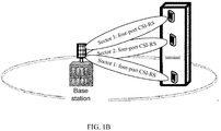
- Fig.1A shows an active antenna with four ports.
- a vertical dimension of a base station is segmented into three sectors, i.e., sector 1, sector 2 and sector 3, which may provide services to respective terminals therein.
- Each sector is allocated with a set of Channel State Information-Reference Signal (CSI-RS) resources, including several CSI-RS ports, e.g., four CSI-RS ports.
- CSI-RS Channel State Information-Reference Signal
- one CSI-RS resource is configured for the network side device at each of the horizontal dimension and the vertical dimension, and each CSI-RS resource is transmitted from a set of antennae to the UE.
- the UE measures the CSI-RS resource at the vertical dimension and generates the corresponding CSI, and measures the CSI-RS resource at the horizontal dimension and generating the corresponding CSI.
- the network side device acquires information about downlink three-dimensional Multiple Input Multiple Output (3D-MIMO) beamforming based on the vertical-dimension CSI and the horizontal-dimension CSI from the UE.
- 3D-MIMO Three-dimensional Multiple Input Multiple Output
- the UE needs to feed back two pieces of CSI, each including a Rank Indicator (RI), a Pre-coding Matrix Indicator (PMI) and a Channel Quality Indicator (CQI), so there is a relatively large uplink feedback overhead.
- RI Rank Indicator
- PMI Pre-coding Matrix Indicator
- CQI Channel Quality Indicator
- the present disclosure provides a CSI feedback method, a CSI feedback device and a CSI feedback system, so as to reduce the uplink feedback overhead as compared with the conventional CSI feedback approach.
- the present disclosure provides in some embodiments a CSI feedback method.
- the CSI feedback method includes: configuring, by a network side device, a first downlink channel measurement pilot for a UE; and receiving, by the network side device, first PMI information fed back by the UE, the first PMI information being acquired by the UE based on measurement of the first downlink channel measurement pilot and second PMI information.
- a dimension represented by the first PMI information is different from a dimension represented by the second PMI information.
- the UE According to the CSI feedback method in the embodiments of the present disclosure, it is merely necessary for the UE to feed the first PMI information back to the network side device to enable the network side device to perform a beamforming operation based on the first PMI information. As a result, it is possible to remarkably reduce an uplink feedback overhead as compared with the related art.
- the CSI feedback method further includes performing, by the network side device, a beamforming operation on a signal to be transmitted to the UE based on the first PMI information and the second PMI information.
- the CSI feedback method further includes receiving, by the network side device, CQI information fed back by the UE, the CQI information being determined by the UE based on the first PMI information and the second PMI information.
- the CSI feedback method further includes performing, by the network side device, a link adjustment on the signal to be transmitted to the UE based on the CQI information.
- the CSI feedback method further includes configuring, by the network side device, second PMI information for the UE to enable the UE to determine the first PMI information based on the second PMI information configured for the UE and the first downlink channel measurement pilot and determine the CQI information based on the first PMI information and the second PMI information configured for the UE.
- a step of determining, by the network side device, the second PMI information includes: receiving, by the network side device, the second PMI information reported by the UE; or measuring, by the network side device, an uplink signal from the UE so as to determine the second PMI information.
- the CSI feedback method further includes, prior to receiving, by the network side device, the second PMI information reported by the UE: configuring, by the network side device, a second downlink channel measurement pilot for the UE, so as to enable the UE to determine the second PMI information based on the second downlink channel measurement pilot; or configuring, by the network side device, a two-dimensional joint antenna array downlink channel measurement pilot for the UE, so as to enable the UE to determine the second PMI information based on the two-dimensional joint antenna array downlink channel measurement pilot.
- the step of configuring, by the network side device, the second PMI information for the UE includes: transmitting, by the network side device, the second PMI information to the UE to enable the UE to determine the first PMI information based on the received second PMI information, the first downlink channel measurement pilot and the second downlink channel measurement pilot in the event that the network side device configures the second downlink channel measurement pilot for the UE, and enable the UE to determine the first PMI information based on the received second PMI information and the two-dimensional joint antenna array downlink channel measurement pilot in the event that the network side device configures the two-dimensional joint antenna array downlink channel measurement pilot for the UE; or notifying, by the network side device, the UE to use the second PMI information determined by the UE to enable the UE to determine the first PMI information based on the second PMI information determined by the UE, the first downlink channel measurement pilot and the second downlink channel measurement pilot in the event that the network side device configures the second downlink channel measurement pilot for
- the present disclosure provides in some embodiments a CSI feedback method, including steps of: determining, by a UE, first PMI information based on second PMI information and a first downlink channel measurement pilot configured by a network side device; and feeding, by the UE, the first PMI information back to the network side device.
- a dimension represented by the first PMI information is different from a dimension represented by the second PMI information.
- the UE it is merely necessary for the UE to feed the first PMI information back to the network side device, so as to enable the network side device to perform a beamforming operation based on the first PMI information.
- the network side device it is possible to remarkably reduce an uplink feedback overhead as compared with the related art.
- the CSI feedback method further includes: determining, by the UE, CQI information based on the first PMI information and the second PMI information; and feeding, by the UE, the CQI information back to the network side device.
- a step of determining, by the UE, the second PMI information includes: measuring, by the UE, a downlink pilot signal so as to determine the second PMI information; or determining, by the UE, the second PMI information based on second PMI information configured by the network side device.
- the step of measuring, by the UE, the downlink pilot signal so as to determine the second PMI information includes measuring, by the UE, a second downlink channel measurement pilot or a two-dimensional joint antenna array downlink channel measurement pilot configured by the network side device, so as to determine the second PMI information.
- the step of determining, by the UE, the first PMI information based on the second PMI information and the first downlink channel measurement pilot configured by the network side device includes: determining, by the UE, the first PMI information based on the second PMI information, and the first downlink channel measurement pilot configured by the network side and the second downlink channel measurement pilot; or measuring, by the UE, a downlink pilot signal based on the second PMI information and the two-dimensional joint antenna array downlink channel measurement pilot configured by the network side device, so as to determine the first PMI information.
- the CSI feedback method further includes, subsequent to the step of measuring, by the UE, the downlink pilot signal so as to determine the second PMI information: reporting, by the UE, the determined second PMI information to the network side device.
- the CSI feedback method further includes, subsequent to the step of reporting, by the UE, the determined second PMI information to the network side device: after the UE receives the second PMI information from the network side device, using the received second PMI information as second PMI information for determining the first PMI information and the CQI information; or after the UE receives an acknowledgement message from the network side device, using the reported second PMI information as second PMI information for determining the first PMI information and the CQI information.
- the present disclosure provides in some embodiments a network side device.
- the network side device includes: a configuration module configured to configure a first downlink channel measurement pilot for a UE; and a reception module configured to receive first PMI information from the UE, the first PMI information being acquired by the UE based on measurement of the first downlink channel measurement pilot and second PMI information.
- a dimension represented by the first PMI information is different from a dimension represented by the second PMI information.
- the network side device in the embodiments of the present disclosure, it is merely necessary for the UE to feed back the first PMI information to the network side device, so as to enable the network side device to perform a beamforming operation based on the first PMI information. As a result, it is possible to remarkably reduce an uplink feedback overhead as compared with the related art.
- the network side device further includes a processing module configured to perform a beamforming operation on a signal to be transmitted to the UE based on the first PMI information and the second PMI information.
- the reception module is further configured to receive CQI information fed back by the UE, the CQI information being determined by the UE based on the first PMI information and the second PMI information.
- the processing module is further configured to perform a link adjustment on the signal to be transmitted to the UE based on the CQI information.
- the configuration module is further configured to configure second PMI information for the UE, so as to enable the UE to determine the first PMI information based on the second PMI information and the first downlink channel measurement pilot configured for the UE and determine the CQI information based on the first PMI information and the second PMI information configured for the UE.
- the network side device further includes a determination module configured to receive the second PMI information reported by the UE; or measure an uplink signal from the UE so as to determine the second PMI information.
- the configuration module is further configured to, before the determination module receives the second PMI information reported by the UE, configure a second downlink channel measurement pilot for the UE, so as to enable the UE to determine the second PMI information based on the second downlink channel measurement pilot; or configure a two-dimensional joint antenna array downlink channel measurement pilot for the UE, so as to enable the UE to determine the second PMI information based on the two-dimensional joint antenna array downlink channel measurement pilot.
- the configuration module is further configured to: transmit the second PMI information to the UE to, enable the UE to determine the first PMI information based on the configured second PMI information, the first downlink channel measurement pilot and the second downlink channel measurement pilot in the event that the network side device configures the second downlink channel measurement pilot for the UE, and enable the UE to determine the first PMI information based on the configured second PMI information and the two-dimensional joint antenna array downlink channel measurement pilot in the event that the network side device configures the two-dimensional joint antenna array downlink channel measurement pilot for the UE; or notify the UE to use the second PMI information determined by the UE to enable the UE to determine the first PMI information based on the second PMI information determined by the UE, the first downlink channel measurement pilot and the second downlink channel measurement pilot in the event that the network side device configures the second downlink channel measurement pilot for the UE, and enable the UE to determine the first PMI information based on the second PMI information determined by the UE and
- the present disclosure provides in some embodiments a UE.
- the UE includes: a first determination module configured to determine first PMI information based on second PMI information and a first downlink channel measurement pilot configured by a network side device; and a transmission module configured to feed the first PMI information back to the network side device.
- a dimension represented by the first PMI information is different from a dimension represented by the second PMI information.
- the UE in the embodiments of the present disclosure, it is merely necessary for the UE to feed the first PMI information back to the network side device, so as to enable the network side device to perform a beamforming operation based on the first PMI information. As a result, it is possible to remarkably reduce an uplink feedback overhead as compared with the related art.
- the first determination module is further configured to determine CQI information based on the first PMI information and the second PMI information
- the transmission module is further configured to feed the CQI information back to the network side device.
- the UE further includes a second determination module configured to measure a downlink pilot signal so as to determine the second PMI information, or determine the second PMI information based on second PMI information configured by the network side device.
- the second determination module is further configured to measure a downlink pilot signal based on a second downlink channel measurement pilot or a two-dimensional joint antenna array downlink channel measurement pilot configured by the network side device, so as to determine the second PMI information.
- the first determination module is further configured to determine the first PMI information based on the second PMI information and the first downlink channel measurement pilot and the second downlink channel measurement pilot configured by the network side device, or measure the downlink pilot signal based on the second PMI information and the two-dimensional joint antenna array downlink channel measurement pilot configured by the network side device so as to determine the first PMI information.
- the transmission module is further configured to report the determined second PMI information to the network side device, after the second determination module measures the downlink pilot signal and determines the second PMI information.
- the UE further includes a third determination module configured to, after the transmission module reports the determined second PMI information to the network side device: after receiving the second PMI information from the network side device, determine the received second PMI information as second PMI information for determining the first PMI information and the CQI information; or after receiving an acknowledgement message from the network side device, use the reported second PMI information as second PMI information for determining the first PMI information and the CQI information.
- a third determination module configured to, after the transmission module reports the determined second PMI information to the network side device: after receiving the second PMI information from the network side device, determine the received second PMI information as second PMI information for determining the first PMI information and the CQI information; or after receiving an acknowledgement message from the network side device, use the reported second PMI information as second PMI information for determining the first PMI information and the CQI information.
- the present disclosure provides in some embodiments a CSI feedback system.
- the CSI feedback system includes a network side device and a UE.
- the network side device is configured to configure a first downlink channel measurement pilot for the UE, and receive first PMI information fed back by the UE.
- the UE is configured to determine the first PMI information based on second PMI information and the first downlink channel measurement pilot configured by the network side device, and feed the first PMI information back to the network side device.
- a dimension represented by the first PMI information is different from a dimension represented by the second PMI information.
- the UE it is merely necessary for the UE to feed the first PMI information back to the network side device, so as to enable the network side device to perform a beamforming operation based on the first PMI information.
- the network side device it is possible to remarkably reduce an uplink feedback overhead as compared with the related art.
- the present disclosure provides in some embodiments a network side device.
- the network side device includes: a processor; a memory connected to the processor via a bus interface and configured to store programs and data used when the processor performs an operation; and a transceiver connected to the processor and the memory via the bus interface and configured to receive and transmit the data under the control of the processor.
- the processor is further configured to call and execute the programs and data stored in the memory, so as to: configure a first downlink channel measurement pilot for a UE, and receive first PMI information from the UE.
- the first PMI information is acquired by the UE based on measurement of the first downlink channel measurement pilot and second PMI information.
- a dimension represented by the first PMI information is different from a dimension represented by the second PMI information.
- the network side device in the embodiments of the present disclosure, it is merely necessary for the UE to feed the first PMI information back to the network side device, so as to enable the network side device to perform a beamforming operation based on the first PMI information. As a result, it is possible to remarkably reduce an uplink feedback overhead as compared with the related art.
- the present disclosure provides in some embodiments a UE.
- the UE includes: a processor; a memory connected to the processor via a bus interface and configured to store programs and data used when the processor performs an operation; and a transceiver connected to the processor and the memory via the bus interface and configured to receive and transmit the data under the control of the processor.
- the processor is further configured to call and execute the programs and data stored in the memory, so as to determine first PMI information based on second PMI information and a first downlink channel measurement pilot configured by a network side device, and feed the first PMI information back to the network side device.
- a dimension represented by the first PMI information is different from a dimension represented by the second PMI information.
- the UE in the embodiments of the present disclosure, it is merely necessary for the UE to feed the first PMI information back to the network side device, so as to enable the network side device to perform a beamforming operation based on the first PMI information. As a result, it is possible to remarkably reduce an uplink feedback overhead as compared with the related art.
- a network side device may configure a first downlink channel measurement pilot for a UE and receive first PMI information from the UE.
- the first PMI information is acquired by the UE based on second PMI information and measurement of the first downlink channel measurement pilot, and a dimension represented by the first PMI information is different from a dimension represented by the second PMI information.
- the network side device only receives the first PMI information, which is acquired by the UE based on the second PMI information and the measurement of the first downlink channel measurement pilot, from the UE, and then process a signal to be transmitted to the UE based on the first PMI information.
- the first PMI information is selected by the UE from a codebook of a first dimension based on the second PMI information and the measurement information about the first downlink channel measurement pilot, and the first PMI information corresponds to a beamforming vector achieving an optimal beamforming performance.
- PMI1 is acquired by merely measuring a CSI-RS resource in the horizontal dimension or the vertical dimension, and is irrelevant to a CSI-RS resource in the other dimension.
- the network side device may perform the beamforming operation on the signal to be transmitted to the UE based on the first PMI information and the second PMI information, and receive CQI information from the UE.
- the CQI information is acquired by the UE based on the first PMI information and the second PMI information.
- the network side device may directly perform a link adjustment on the signal to be transmitted to the UE based on the CQI information, so as to remarkably simplify the network side device.
- the CSI includes a RI, a PMI and a CQI.
- the RI is used to represent the number of downlink code streams capable of being supported by the UE
- the PMI is used to represent an index number of a pre-coding matrix in a codebook fed from the UE
- the CQI is used to represent the strength of a signal that may be received by the UE in the event that the RI/PMI is subjected to an MIMO encoding operation.
- the CQI must be determined on the basis of the RI/PMI, and may represent signal strength, e.g., Signal to Interference plus Noise Ratio (SINR), Modulation and Coding Scheme that may be accepted, or any other characteristics.
- SINR Signal to Interference plus Noise Ratio
- the number of CQI may be adjusted based on the RI.
- the implementation of the network side device will precede the implementation of the UE.
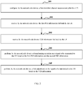
- the present disclosure provides in some embodiments a CSI feedback method for a network side device, which includes the following steps.
- the network side device may perform a downlink adjustment on the signal to be transmitted to the UE based on the CQI information.
- step 205 is a preferred step in the embodiments of the present disclosure.
- the CQI information is determined by the UE based on the first PMI information and the second PMI information, so upon the receipt of the CQI information, the network side device may perform the downlink adjustment on the signal to be transmitted to the UE directly using the CQI information.
- the network side device may configure the second PMI information for the UE, so as to enable the UE to determine the first PMI information based on the second PMI information configured for the UE and the first downlink channel measurement pilot, and determine the CQI information based on the first PMI information and the second PMI information configured for the UE.
- the network side device may determine the second PMI information in step 203 and/or that configured for the UE in one of the following two approaches, or a combination thereof.
- the network side device may receive the second PMI information reported by the UE, and then determine the second PMI information in step 203 and/or that configured for the UE based on the reported second PMI information.
- the network side device may also receive a second RI from the UE.
- a dimension represented by the first RI is different from a dimension represented by the second RI.
- the network side device may measure an uplink signal from the UE, so as to determine the second PMI information.
- the uplink signal may be an uplink pilot signal, e.g., a Sounding Reference Signal (SRS), or a Demodulation Reference Symbol (DRS) transmitted along with a Physical Uplink Shared Channel (PUSCH).
- SRS Sounding Reference Signal
- DRS Demodulation Reference Symbol
- the determination of the second PMI information may be achieved through the following steps.
- the determination of the second PMI information through the above two steps is merely a possible way in the embodiments of the present disclosure, and the network side device may measure the uplink signal from the UE so as to determine the second PMI information in any other ways, which is not limited herein.
- the second PMI information obtained in the first and second approaches may be processed on the basis of a preset algorithm (e.g., an averaging process, or an extremum (e.g., maximum or minimum value) calculation process) so as to obtain final second PMI information, and then this final second PMI information may be taken as the second PMI information in step 203 and/or that configured for the UE.
- a preset algorithm e.g., an averaging process, or an extremum (e.g., maximum or minimum value) calculation process
- the determination of the second PMI information in Step 203 and/or that configured for the UE by the network side device is not limited to the above-mentioned first and second approaches, and any other modes may also be used, which is not limited herein.
- the above-mentioned second approach may be applied to an uplink/downlink channel reciprocity system.
- uplink and downlink channels have identical characteristics, so the second PMI information acquired by the network side device through measuring the uplink signal is equivalent to the second PMI information acquired by the UE through the measurement of the downlink pilot signal, i.e., the second PMI information may be determined in the above-mentioned second approach.
- the uplink/downlink channel reciprocity system includes a TDD system, or a FDD system where a difference between an uplink frequency and a downlink frequency is small relative to a carrier frequency (in this case, the uplink channel is equivalent to the downlink channel to some extent, i.e., the uplink and downlink channels have identical characteristics).
- the UE may determine and report the second PMI information directly using the joint antenna array CSI-RS resource.
- the network side device may, prior to receiving the second PMI information reported by the UE, configure a resource for the UE in one of the following two resource configuration approaches to facilitate the UE reporting the second PMI information.
- the resource may also be configured in any other approaches, as long as the UE can determine the second PMI information to be reported based on the resource.
- Resource configuration approach 1 the network side device may configure a second downlink channel measurement pilot for the UE, so as to enable the UE to determine the second PMI information based on the second downlink channel measurement pilot.
- the network side device may configure a two-dimension joint antenna array downlink channel measurement pilot for the UE, so as to enable the UE to determine the second PMI information based on the two-dimension joint antenna array downlink channel measurement pilot.
- the UE may determine the second PMI information based on the joint antenna array downlink channel measurement pilot, so the two-dimensional joint antenna array downlink channel measurement pilot may not be configured for the UE through the above-mentioned resource configuration approaches (1) and (2).
- the downlink channel measurement pilot is a CSI-RS resource and the network side device includes a 4*8 antenna array (32 antennae in total).
- the second downlink channel measurement pilot configured for the UE in the event that the first downlink channel measurement pilot configured by the network side device for the UE at step 201 is a four-port CSI-RS resource, the second downlink channel measurement pilot configured for the UE is an eight-port CSI-RS resource; in the event that the first downlink channel measurement pilot configured by the network side device for the UE at step 201 is an eight-port CSI-RS resource, the second downlink channel measurement pilot configured for the UE is a four-port CSI-RS resource.
- the first downlink channel measurement pilot configured by the network side device for the UE at step 201 is a four-port CSI-RS resource, an eight-port CSI-RS resource or a thirty two-port CSI-RS resource, a thirty two-port CSI-RS resource may be configured for the UE, and this thirty two-port CSI-RS resource is the two-dimensional joint antenna array downlink channel measurement pilot.
- LTE Long Term Evolution
- the network side device In order to ensure that the network side device and the UE use the same second PMI information to process relevant information (e.g., the determination of the pre-coding matrix by the network side device, and the determination of the first PMI information and the CQI information by the UE), thereby to ensure the accuracy of the CSI from the UE and the accuracy of the subsequent beamforming and signal adjustment operations, the network side device needs to confirm the second PMI information with the UE.
- the network side device may configure the second PMI information for the UE through one of the following two ways.
- the network side device may transmit the second PMI information to the UE, so as to: in the event that the network side device has configured the second downlink channel measurement pilot for the UE, enable the UE to determine the first PMI information based on the configured second PMI information, the first downlink channel measurement pilot and the second downlink channel measurement pilot, and in the event that the network side device has configured the two-dimensional joint antenna array downlink channel measurement pilot for the UE, enable the UE to determine the first PMI information based on the configured second PMI information and the two-dimensional joint antenna array downlink channel measurement pilot, and enable the UE to determine the CQI information based on the first PMI information and the second PMI information.
- the network side device may notify the UE to use the second PMI information determined by the UE itself, so as to: in the event that the network side device has configured the second downlink channel measurement pilot for the UE, enable the UE to determine the first PMI information based on the second PMI information determined by the UE, the first downlink channel measurement pilot and the second downlink channel measurement pilot, and in the event that the network side device has configured the two-dimensional joint antenna array downlink channel measurement pilot for the UE, enable the UE to determine the first PMI information based on the second PMI information determined by the UE and the two-dimensional joint antenna array downlink channel measurement pilot, and enable the UE to determine the CQI information based on the first PMI information and the second PMI information.
- the network side device and the UE may confirm the second PMI information in any other ways, or the network side device and the UE may confirm the second PMI information based on a preset agreement (e.g., the UE may use the latest reported second PMI information, and the network side device may use the latest second PMI information reported by the UE) without any interaction.
- a preset agreement e.g., the UE may use the latest reported second PMI information, and the network side device may use the latest second PMI information reported by the UE
- the network side device in the embodiments of the present disclosure may be a base station (e.g., a macro base station or a Femtocell), or a relay node (RN) device, or any other network side device.
- a base station e.g., a macro base station or a Femtocell
- RN relay node
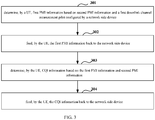
- the present disclosure provides in some embodiments a CSI feedback method for a UE which includes the following steps.
- steps 303 and 304 are preferred steps in the embodiments of the present disclosure.
- step 303 may be performed subsequent to step 301, and in the event that step 303 is performed between step 301 and step 302, step 304 may be performed at the same time with, or subsequent to, step 302, i.e., the performing order of these steps is not limited herein.
- the CQI information determined in step 303 is CQI information (e.g., highest Modulation Coding Scheme (MCS) or SNR) that may be measured by the UE in the event that the beamforming operation and the data transmission (e.g., over a Physical Downlink Shared Channel (PDSCH)) are performed by the network side device based on the first PMI information (and the first RI information) and the second PMI information (at the second RI information) reported by the UE.
- CQI information e.g., highest Modulation Coding Scheme (MCS) or SNR
- MCS Modulation Coding Scheme
- SNR Physical Downlink Shared Channel
- the conventional CQI information refers to CQI information that may be measured by the UE in the event that the beamforming operation and the downlink data transmission are performed by the network side device based on a single piece of PMI/RI information reported by the UE.
- the single piece of PMI/RI information is acquired by the UE through the measurement of the horizontal-dimension CSI-RS resource or the vertical-dimension CSI-RS resource.
- Step 303 may include the following steps.
- SNR represents a signal-to-noise ration.
- Parameters G, H, a, V1, V2, H1 and H2 have meanings identical to those in the above-mentioned equations (1), (2) and (3), and thus will not be repeated herein.
- the UE may determine the second PMI information in any one of the following two ways. In a first way, the UE may measure a downlink pilot signal, so as to determine the second PMI information. In a second way, the UE may determine the second PMI information based on the second PMI information transmitted from the network side device.
- the downlink pilot signal includes a CSI-RS resource or a CRS.
- the UE may measure the second downlink channel measurement pilot or the two-dimension joint antenna array downlink channel measurement pilot configured by the network side device, so as to determine the second PMI information.
- the above-mentioned step 301 may include: determining, by the UE, the first PMI information based on the second PMI information, and the first downlink channel measurement pilot and the second downlink channel measurement pilot configured by the network side device; or measuring, by the UE, a downlink pilot signal based on the second PMI information and the two-dimension joint antenna array downlink channel measurement pilot configured by the network side device, so as to determine the first PMI information.
- the UE may measure the downlink pilot signal based on the second downlink channel measurement pilot or the two-dimension joint antenna array downlink channel measurement pilot configured by the network side device, so as to determine the second channel information.
- the method may further include reporting, by the UE, the determined second PMI information to the network side device.
- the method may further include: after receiving the second PMI information configured by the network side device, determining, by the UE, the first PMI information and the CQI information based on the second PMI information; or after receiving an acknowledgement message from the network side device, using, by the UE, the reported second PMI information as the PMI information for determining the first PMI information and the CQI information.
- the CSI measured by the UE on each CSI-RS resource merely reflects a channel state on the current CSI-RS resource, so it merely reflects a channel in one dimension.
- the pieces of CSI measured on the CSI-RS resources in different dimensions are completely independent of each other, so upon the receipt of the CSI information of different dimensions, the network side device may not directly use the CSI information for the 3D-MIMO downlink transmission, and instead, the network side device must acquire the downlink 3D-MIMO beamforming information and the CQI information for the downlink link adjustment based on the CSI information of different dimensions.
- the complexity of an eNB may be increased and the downlink transmission accuracy may be decreased.
- the UE may determine the first PMI information based on the first downlink channel measurement pilot and the second PMI information, and feed back the first PMI information to the network side device.
- the network side device may perform the beamforming operation based on the first PMI information.
- the UE merely needs to feed back the first PMI information to the network side device, so as compared with the related art where two independent pieces of CSI information each including RI, PMI and CQI information are provided, it is possible to remarkably reduce an uplink feedback overhead.
- the first PMI information determined by the UE is PMI corresponding to the beamforming vector capable of achieving the optimal beamforming performance and selected from a codebook in a first dimension.
- the second PMI information is utilized and the PMI information corresponds to the beamforming vector capable of achieving the optimal beamforming performance, so the first PMI information from the UE may have relatively high accuracy, and in the event of performing the beamforming operation based on the first PMI information, it is possible to remarkably increase the downlink transmission accuracy.
- the UE may determine and feed back the CQI information based on the first PMI information and the second PMI information.
- the CQI information which is determined based on the first PMI information and the second PMI information may reflect the overall channel quality in different dimensions, so the network side device may directly perform the downlink adjustment on the signal to be transmitted to the UE based on the CQI information determined and fed back by the UE, and as compared with the related art where the network side device determines the CQI information based on the PMI information of different dimensions, it is possible to remarkably simplify the network side device.
- the network side device includes: a configuration module 41 configured to configure a first downlink channel measurement pilot for a UE; and a reception module 42 configured to receive first PMI information from the UE.
- the first PMI information is acquired by the UE based on measurement of the first downlink channel measurement pilot and second PMI information.
- a dimension represented by the first PMI information is different from a dimension represented by the second PMI information.
- the network side device further includes a processing module 43 configured to perform a beamforming operation on a signal to be transmitted to the UE based on the first PMI information and the second PMI information.
- the reception module 42 is further configured to receive CQI information from the UE.
- the CQI information is determined by the UE based on the first PMI information and the second PMI information.
- the processing module 43 is further configured to perform link adjustment on the signal to be transmitted to the UE based on the CQI information.
- the configuration module 41 is further configured to configure second PMI information for the UE, so as to enable the UE to determine the first PMI information based on the second PMI information and the first downlink channel measurement pilot and determine the CQI information based on the first PMI information and the second PMI information.
- the network side device further includes a determination module 44 configured to receive the second PMI information reported by the UE; or measure an uplink signal from the UE so as to determine the second PMI information.
- the configuration module 41 is further configured to, before the determination module has received the second PMI information reported by the UE, configure a second downlink channel measurement pilot for the UE, so as to enable the UE to determine the second PMI information based on the second downlink channel measurement pilot; or configure a two-dimensional joint antenna array downlink channel measurement pilot for the UE, so as to enable the UE to determine the second PMI information based on the two-dimensional joint antenna array downlink channel measurement pilot.
- the configuration module 41 is further configured to: transmit the second PMI information to the UE, so as to, in the event that the network side device has configured the second downlink channel measurement pilot for the UE, enable the UE to determine the first PMI information based on the second PMI information, the first downlink channel measurement pilot and the second downlink channel measurement pilot, and in the event that the network side device has configured the two-dimensional joint antenna array downlink channel measurement pilot for the UE, enable the UE to determine the first PMI information based on the second PMI information and the two-dimensional joint antenna array downlink channel measurement pilot, and enable the UE to determine the CQI information based on the first PMI information and the second PMI information; or notify the UE to use the second PMI information determined by the UE itself, so as to, in the event that the network side device has configured the second downlink channel measurement pilot for the UE, enable the UE to determine the first PMI information based on the second PMI information determined by the UE, the first downlink channel
- the UE includes a first determination module 51 and a transmission module 52.
- the first determination module 51 is configured to determine first PMI information based on second PMI information and a first downlink channel measurement pilot configured by a network side device. A dimension represented by the first PMI information is different from a dimension represented by the second PMI information.
- the transmission module 52 is configured to feed back the first PMI information to the network side device.
- the first determination module 51 is further configured to determine CQI information based on the first PMI information and the second PMI information
- the transmission module 52 is further configured to feed back the CQI information to the network side device.
- the UE further includes a second determination module 53 configured to measure a downlink pilot signal so as to determine the second PMI information, or determine the second PMI information based on the received second PMI information transmitted from the network side device.
- a second determination module 53 configured to measure a downlink pilot signal so as to determine the second PMI information, or determine the second PMI information based on the received second PMI information transmitted from the network side device.
- the second determination module 53 is further configured to measure a two-dimensional joint antenna array downlink channel measurement pilot or a second downlink channel measurement pilot configured by the network side device, so as to determine the second PMI information.
- the first determination module 51 is further configured to determine the first PMI information based on the second PMI information and the second downlink channel measurement pilot and the first downlink channel measurement pilot configured by the network side device, or measure the downlink pilot signal based on the second PMI information and the two-dimensional joint antenna array downlink channel measurement pilot configured by the network side device so as to determine the first PMI information.
- the transmission module 52 is further configured to, after the second determination module has measured the downlink pilot signal and determined the second PMI information, report the determined second PMI information to the network side device.
- the UE further includes a third determination module 54 configured to: after the transmission module has reported the determined second PMI information to the network side device, upon the receipt of the second PMI information from the network side device, use the received second PMI information as the second PMI information used for determining the first PMI information and the CQI information; or upon the receipt of an acknowledgement message from the network side device, use the reported second PMI information as the second PMI information used for determining the first PMI information and the CQI information.
- a third determination module 54 configured to: after the transmission module has reported the determined second PMI information to the network side device, upon the receipt of the second PMI information from the network side device, use the received second PMI information as the second PMI information used for determining the first PMI information and the CQI information; or upon the receipt of an acknowledgement message from the network side device, use the reported second PMI information as the second PMI information used for determining the first PMI information and the CQI information.
- the CSI feedback system includes a network side device 61 and a UE 62.
- the network side device 61 is configured to configure a first downlink channel measurement pilot for the UE, and receive first PMI information from the UE.
- a dimension represented by the first PMI information is different from a dimension represented by the second PMI information.
- the UE 62 is configured to determine the first PMI information based on second PMI information and the first downlink channel measurement pilot configured by the network side device, and feed back the first PMI information to the network side device.
- the network side device 61 is further configured to perform a beamforming operation on a signal to be transmitted to the UE based on the first PMI information and the second PMI information.
- the network side device 61 is further configured to receive CQI information from the UE, and the UE 62 is further configured to determine the CQI information based on the first PMI information and the second PMI information and feed back the CQI information to the network side device.
- the network side device 61 is further configured to perform a link adjustment on the signal to be transmitted to the UE based on the CQI information.
- the network side device 61 is further configured to configure the second PMI information for the UE, so as to enable the UE to determine the first PMI information based on the second PMI information and the first downlink channel measurement pilot configured for the UE and determine the CQI information based on the first PMI information and the second PMI information configured for the UE.
- the UE 62 is further configured to measure a downlink pilot signal so as to determine the second PMI information, or determine the second PMI information based on the second PMI information configured by the network side device.
- the network side device 61 is further configured to receive the second PMI information reported by the UE, or measure an uplink signal from the UE so as to determine the second PMI information.
- the UE 62 is further configured to measure the downlink pilot signal so as to determine the second PMI information, and then report the determined second PMI information to the network side device.
- the network side device 61 is further configured to receive the second PMI information reported by the UE, or measure the uplink signal form the UE so as to determine the second PMI information.
- the UE 62 is further configured to report the determined second PMI information to the network side device.
- the network side device 61 is further configured to, before receiving the second PMI information reported by the UE, configure a second downlink channel measurement pilot for the UE, so as to enable the UE to determine the second PMI information based on the second downlink channel measurement pilot; or configure a two-dimensional joint antenna array downlink channel measurement pilot for the UE, so as to enable the UE to determine the second PMI information based on the two-dimensional joint antenna array downlink channel measurement pilot.
- the UE 62 is further configured to measure the second downlink channel measurement pilot or the two-dimensional joint antenna array downlink channel measurement pilot configured by the network side device, so as to determine the second PMI Information; and determine the first PMI information based on the second PMI information and the first downlink channel measurement pilot and the second downlink channel measurement pilot configured by the network side device, or measure a downlink pilot signal based on the second PMI information and the two-dimensional joint antenna array downlink channel measurement pilot configured by the network side, so as to determine the first PMI information.
- the network side device 61 is further configured to transmit the second PMI information to the UE, so as to, in the event that the network side device has configured the second downlink channel measurement pilot for the UE, enable the UE to determine the first PMI information based on the second PMI information, the first downlink channel measurement pilot and the second downlink channel measurement pilot, and in the event that the network side device has configured the two-dimensional joint antenna array downlink channel measurement pilot for the UE, enable the UE to determine the first PMI information based on the second PMI information and the two-dimensional joint antenna array downlink channel measurement pilot, and enable the UE to determine the CQI information based on the first PMI information and the second PMI information; or notify the UE to use the second PMI information determined by the UE itself, so as to, in the event that the network side device has configured the second downlink channel measurement pilot for the UE, enable the UE to determine the first PMI information based on the second PMI information determined by the UE, the first downlink
- the UE 62 is further configured to, after the determined second PMI information has been reported to the network side device, upon the receipt of the second PMI information from the network side device, use the received second PMI information as the second PMI information used for determining the first PMI information and the CQI information; or upon the receipt of an acknowledgement message from the network side device, use the reported second PMI information as the second PMI information used for determining the first PMI information and the CQI information.
- the network side device includes a processor 700, a transceiver 710 and a memory 720 which communicate with each other via a bus interface.
- the processor 700 is configured to read programs stored in the memory 720, so as to configure a first downlink channel measurement pilot for a UE, and receive first PMI information from the UE through the transceiver 710.
- the first PMI information is acquired by the UE based on measurement of the first downlink channel measurement pilot and second PMI information.
- a dimension represented by the first PMI information is different from a dimension represented by the second PMI information.
- the transceiver 710 is configured to receive and transmit data under the control of the processor 700.
- the processor 700 is further configured to read the programs stored in the memory 720, so as to perform a beamforming operation on a signal to be transmitted to the UE based on the first PMI information and the second PMI information.
- the processor 700 is further configured to read the programs stored in the memory 720, so as to receive CQI information fed back by the UE through the transceiver 710.
- the CQI information is determined by the UE based on the first PMI information and the second PMI information.
- the processor 700 is further configured to read the programs stored in the memory 720, so as to perform a link adjustment on the signal to be transmitted to the UE based on the CQI information.
- the processor 700 is further configured to read the programs stored in the memory 720, so as to configure second PMI information for the UE, so as to enable the UE to determine the first PMI information based on the second PMI information configured for the UE and the first downlink channel measurement pilot and determine the CQI information based on the first PMI information and the second PMI information configured for the UE.
- the processor 700 is further configure dot read the programs stored in the memory 720, so as to receive the second PMI information reported by the UE through the transceiver 710, or measure an uplink signal from the UE so as to determine the second PMI information.
- the processor 700 is further configured to read the programs stored in the memory 720, so as to, before the second PMI information reported by the UE has been received through the transceiver 710, configure a second downlink channel measurement pilot for the UE, so as to enable the UE to determine the second PMI information based on the second downlink channel measurement pilot; or configure a two-dimensional joint antenna array downlink channel measurement pilot for the UE, so as to enable the UE to determine the second PMI information based on the two-dimensional joint antenna array downlink channel measurement pilot.
- the processor 700 is further configured to read the programs stored in the memory 720, so as to: transmit the second PMI information to the UE through the transceiver 710, so as to, in the event that the network side device has configured the second downlink channel measurement pilot for the UE, enable the UE to determine the first PMI information based on the configured second PMI information, the first downlink channel measurement pilot and the second downlink channel measurement pilot, and in the event that the network side device has configured the two-dimensional joint antenna array downlink channel measurement pilot for the UE, enable the UE to determine the first PMI information based on the configured second PMI information and the two-dimensional joint antenna array downlink channel measurement pilot, and enable the UE to determine the CQI information based on the first PMI information and the configured second PMI information; or transmit an acknowledgement message to the UE through the transceiver 710, so as to, in the event that the network side device has configured the second downlink channel measurement pilot for the UE, enable the UE to determine the
- the bus architecture may include any number of buses and bridges connected to each other, so as to connect various circuits for one or more processors presented by the processor 700 and one or more memories presented by the memory 720.
- the bus architecture may be used to connect any other circuits, such as a circuit of a peripheral device, a circuit of a voltage stabilizer and a power management circuit, which will not be repeated herein.
- Bus interfaces are provided, and the transceiver 710 may consist of more than one element, e.g., transmitters and receivers for communication with any other devices over a transmission medium.
- the processor 700 may take charge of managing the bus architecture as well as general processing.
- the memory 720 may store data for the operation of the processor 700.
- the UE includes a processor 800, a transceiver 801, a memory 802 and a user interface 803.
- the processor 800 is configured to read programs stored in the memory 802, so as to determine first PMI information based on second PMI information and a first downlink channel measurement pilot configured by a network side device, and transmit the first PMI information to the network side device through the transceiver 801.
- a dimension represented by the first PMI information is different from a dimension represented by the second PMI information.
- the transceiver 801 is configured to receive and transmit data under the control of the processor 800.
- the processor 800 is further configured to read the programs stored in the memory 802, so as to determine CQI information based on the first PMI information and the second PMI information, and feed back the CQI information to the network side device trough the transceiver 801.
- the processor 800 is further configured to read the programs stored in the memory 802, so as to measure a downlink pilot signal and determine the second PMI information, or determine the second PMI information based on the received second PMI information issued from the network side device through the transceiver 801.
- the processor 800 is further configured to read the programs stored in the memory 802, so as to: measure a second downlink channel measurement pilot or a two-dimensional joint antenna array downlink channel measurement pilot configured by the network side device, determine the second PMI information; and determine the first PMI information based on the second PMI information and the first downlink channel measurement pilot and the second downlink channel measurement pilot configured by the network side device, or measure the downlink pilot signal based on the second PMI information and the two-dimensional joint antenna array downlink channel measurement pilot configured by the network side device so as to determine the first PMI information.
- the processor 800 is further configured to read the programs stored in the memory 802, so as to, after measuring the downlink pilot signal and determining the second PMI information, report the determined second PMI information to the network side device through the transceiver 801.
- the processor 800 is further configured to, after the determined second PMI information has been reported to the network side device through the transceiver 801, read the programs stored in the memory 802, so as to: upon the receipt of the second PMI information from the network side device, use the received second PMI information as the second PMI information used for determining the first PMI information and the CQI information; or upon receiving through the transceiver 801 an acknowledgement message from the network side device, use the reported second PMI information as the second PMI information used for determining the first PMI information and the CQI information.
- the bus architecture may include any number of buses and bridges connected to each other, so as to connect various circuits for one or more processors represented by the processor 800 and one or more memories represented by the memory 802.
- the bus architecture may be used to connect any other circuits, such as a circuit of a peripheral device, a circuit of a voltage stabilizer and a power management circuit, which will not be defined herein.
- Bus interfaces are provided, and the transceiver 1201 may consist of more than one element, e.g., a transmitter and a receiver for communication with any other devices over a transmission medium.
- the user interface 803 may also be provided for devices which are arranged inside or outside the UE, and these devices may include, but not limited to, a keypad, a display, a speaker, a microphone and a joystick.
- the processor 800 may take charge of managing the bus architecture as well as general processing.
- the memory 802 may store data for the operation of the processor 800.
Applications Claiming Priority (2)
| Application Number | Priority Date | Filing Date | Title |
|---|---|---|---|
| CN201410509463.0A CN105530036B (zh) | 2014-09-28 | 2014-09-28 | 信道状态信息反馈方法、设备及系统 |
| PCT/CN2015/089871 WO2016045535A1 (fr) | 2014-09-28 | 2015-09-17 | Procédé, dispositif et système de renvoi d'informations d'état de canal |
Publications (2)
| Publication Number | Publication Date |
|---|---|
| EP3200356A1 true EP3200356A1 (fr) | 2017-08-02 |
| EP3200356A4 EP3200356A4 (fr) | 2017-09-27 |
Family
ID=55580294
Family Applications (1)
| Application Number | Title | Priority Date | Filing Date |
|---|---|---|---|
| EP15844823.3A Pending EP3200356A4 (fr) | 2014-09-28 | 2015-09-17 | Procédé, dispositif et système de renvoi d'informations d'état de canal |
Country Status (4)
| Country | Link |
|---|---|
| US (1) | US10291308B2 (fr) |
| EP (1) | EP3200356A4 (fr) |
| CN (1) | CN105530036B (fr) |
| WO (1) | WO2016045535A1 (fr) |
Cited By (1)
| Publication number | Priority date | Publication date | Assignee | Title |
|---|---|---|---|---|
| EP3993281A4 (fr) * | 2019-07-12 | 2022-11-16 | Huawei Technologies Co., Ltd. | Procédé et dispositif de traitement de précodage |
Families Citing this family (9)
| Publication number | Priority date | Publication date | Assignee | Title |
|---|---|---|---|---|
| JP6731497B2 (ja) * | 2016-05-13 | 2020-07-29 | 華為技術有限公司Huawei Technologies Co.,Ltd. | チャネル状態情報報告方法、チャネル状態情報読み出し方法、及び関連装置 |
| BR112019002672A2 (pt) * | 2016-08-10 | 2019-05-14 | Idac Holdings, Inc. | método de transmissão de enlace ascendente implementado por uma unidade de transmissão/recepção sem fio, e, unidade de transmissão/recepção sem fio |
| CN107733485B (zh) * | 2016-08-12 | 2021-09-03 | 中兴通讯股份有限公司 | 信道状态信息的反馈方法及装置 |
| CN107889220B (zh) | 2016-09-29 | 2022-01-28 | 华为技术有限公司 | 通信方法、基站和终端设备 |
| CN108023717B (zh) * | 2016-11-04 | 2021-08-20 | 华为技术有限公司 | 一种参考信号的测量方法和装置 |
| CN108271174A (zh) * | 2016-12-30 | 2018-07-10 | 华为技术有限公司 | 上行传输的方法、装置和系统 |
| CN108282250B (zh) * | 2017-01-06 | 2021-03-26 | 维沃移动通信有限公司 | 一种下行信道状态信息的测量方法、基站及终端 |
| CN109121206B (zh) * | 2017-06-22 | 2021-08-31 | 华为技术有限公司 | 通信方法及通信节点 |
| CN112262536B (zh) * | 2018-06-27 | 2021-09-07 | 华为技术有限公司 | 一种数据传输方法及装置 |
Family Cites Families (15)
| Publication number | Priority date | Publication date | Assignee | Title |
|---|---|---|---|---|
| CN102158263B (zh) * | 2010-02-11 | 2015-12-02 | 索尼公司 | 基于码书的信道信息反馈方法、设备和系统 |
| CN101867458B (zh) * | 2010-06-21 | 2016-03-02 | 中兴通讯股份有限公司 | 信道状态信息的反馈方法及装置 |
| CN102291212B (zh) * | 2011-08-12 | 2014-06-18 | 电信科学技术研究院 | 信道状态信息的反馈方法和设备 |
| CN103828276A (zh) * | 2012-06-28 | 2014-05-28 | 华为技术有限公司 | 信道状态信息处理方法及终端 |
| CN103716078B (zh) | 2012-09-29 | 2019-03-12 | 中兴通讯股份有限公司 | 一种信道状态信息的处理方法及装置 |
| CN103780332B (zh) | 2012-10-19 | 2017-03-29 | 电信科学技术研究院 | 传输编码指示信息和确定预编码矩阵的方法、系统及设备 |
| CN103840868A (zh) * | 2012-11-20 | 2014-06-04 | 电信科学技术研究院 | 一种指示和反馈信道质量信息的方法、设备及系统 |
| US8971437B2 (en) * | 2012-12-20 | 2015-03-03 | Google Technology Holdings LLC | Method and apparatus for antenna array channel feedback |
| WO2014117352A1 (fr) * | 2013-01-31 | 2014-08-07 | Qualcomm Incorporated | Retour de csi mimo 3d basé sur des ports d'élévation virtuelle |
| CN103152140B (zh) | 2013-03-05 | 2016-03-02 | 东南大学 | 一种基于直积码书的三维多用户mimo有限反馈方法 |
| CN104065448B (zh) * | 2013-03-22 | 2017-11-14 | 电信科学技术研究院 | 一种确定预编码矩阵的方法、系统和设备 |
| WO2015109463A1 (fr) * | 2014-01-22 | 2015-07-30 | Nec Corporation | Méthode et appareil de mesure et de rétroaction de canal |
| CN103825678B (zh) | 2014-03-06 | 2017-03-08 | 重庆邮电大学 | 一种基于Khatri‑Rao积3D MU‑MIMO的预编码方法 |
| WO2015156457A1 (fr) * | 2014-04-09 | 2015-10-15 | Lg Electronics Inc. | Procédé et appareil permettant de réaliser une rétroaction pour une formation de faisceaux basée sur un réseau antennaire massif dans un système de communication sans fil |
| US9405578B2 (en) * | 2014-07-11 | 2016-08-02 | Accenture Global Services Limited | Intelligent application back stack management |
-
2014
- 2014-09-28 CN CN201410509463.0A patent/CN105530036B/zh active Active
-
2015
- 2015-09-17 US US15/514,817 patent/US10291308B2/en active Active
- 2015-09-17 EP EP15844823.3A patent/EP3200356A4/fr active Pending
- 2015-09-17 WO PCT/CN2015/089871 patent/WO2016045535A1/fr active Application Filing
Cited By (2)
| Publication number | Priority date | Publication date | Assignee | Title |
|---|---|---|---|---|
| EP3993281A4 (fr) * | 2019-07-12 | 2022-11-16 | Huawei Technologies Co., Ltd. | Procédé et dispositif de traitement de précodage |
| US11804884B2 (en) | 2019-07-12 | 2023-10-31 | Huawei Technologies Co., Ltd. | Precoding processing method and apparatus |
Also Published As
| Publication number | Publication date |
|---|---|
| WO2016045535A1 (fr) | 2016-03-31 |
| US20170222707A1 (en) | 2017-08-03 |
| US10291308B2 (en) | 2019-05-14 |
| CN105530036B (zh) | 2019-04-02 |
| CN105530036A (zh) | 2016-04-27 |
| EP3200356A4 (fr) | 2017-09-27 |
Similar Documents
| Publication | Publication Date | Title |
|---|---|---|
| US10291308B2 (en) | Channel state information feedback method, device and system | |
| US10659981B2 (en) | Method, system, and device for transmitting preamble signal and for signal measurement | |
| US10778297B2 (en) | Signal transmission method and apparatus | |
| KR102401001B1 (ko) | 부분 프리코딩 csi-rs 및 csi 피드백을 위한 다운링크 시그널링 방법 및 장치 | |
| EP2901568B1 (fr) | Retour d'informations d'état de canal non basé sur des livres de codes | |
| EP3146739B1 (fr) | Notification periodique et aperiodique d'informations d'etat de voie (csi) pour mimo | |
| CN105991231B (zh) | 获取信道状态信息csi的方法及装置 | |
| EP3331181B1 (fr) | Procédé et dispositif de rétroaction et de réception d'informations d'état de canal | |
| EP2813005B1 (fr) | Correction de normalisation de gain de pmi et rétroaction de cqi pour une station de base avec réseau d'antennes | |
| WO2016070706A1 (fr) | Système et procédé pour des signaux de référence d'état de canal ayant subi une formation de faisceau | |
| US9124327B2 (en) | Channel feedback for cooperative multipoint transmission | |
| JP2019537874A (ja) | プリコーディング行列指示方法、装置、及びシステム | |
| US20210203392A1 (en) | Method and device for transmitting and receiving channel state information in wireless communication system using multiple antennas | |
| CN109076572B (zh) | 信道状态信息参考信号发送方法及基站 | |
| KR20170020287A (ko) | 채널 상태 정보 피드백 방법 및 장치 | |
| KR20160086948A (ko) | 채널 상태 정보의 피드백 방법 및 장치 | |
| US10419094B2 (en) | Channel state information measurement method, channel state information acquisition method, terminal and network device | |
| EP3211806B1 (fr) | Procédé et dispositif de retour et d'acquisition d'informations d'état de canal | |
| CN106888062B (zh) | Cqi估计、sinr确定方法及相关设备 | |
| US20180083683A1 (en) | Apparatus and method for feedback of channel state information in wireless communication system | |
| CN111095809A (zh) | 一种测量方法、网络设备和终端设备 | |
| WO2016124078A1 (fr) | Procédé et dispositif de mesure de canal | |
| EP3487141B1 (fr) | Terminal, station de base et procédé permettant d'obtenir des informations de canal | |
| WO2016066036A1 (fr) | Procédé et dispositif de rétroaction et d'acquisition d'informations d'état de canal | |
| US10404430B2 (en) | Method for transmitting pilot signal, base station, and user equipment |
Legal Events
| Date | Code | Title | Description |
|---|---|---|---|
| STAA | Information on the status of an ep patent application or granted ep patent |
Free format text: STATUS: THE INTERNATIONAL PUBLICATION HAS BEEN MADE |
|
| PUAI | Public reference made under article 153(3) epc to a published international application that has entered the european phase |
Free format text: ORIGINAL CODE: 0009012 |
|
| STAA | Information on the status of an ep patent application or granted ep patent |
Free format text: STATUS: REQUEST FOR EXAMINATION WAS MADE |
|
| 17P | Request for examination filed |
Effective date: 20170322 |
|
| AK | Designated contracting states |
Kind code of ref document: A1 Designated state(s): AL AT BE BG CH CY CZ DE DK EE ES FI FR GB GR HR HU IE IS IT LI LT LU LV MC MK MT NL NO PL PT RO RS SE SI SK SM TR |
|
| AX | Request for extension of the european patent |
Extension state: BA ME |
|
| A4 | Supplementary search report drawn up and despatched |
Effective date: 20170825 |
|
| RIC1 | Information provided on ipc code assigned before grant |
Ipc: H04B 7/06 20060101AFI20170821BHEP Ipc: H04B 7/0456 20170101ALI20170821BHEP Ipc: H04L 1/06 20060101ALI20170821BHEP Ipc: H04L 1/00 20060101ALI20170821BHEP |
|
| DAV | Request for validation of the european patent (deleted) | ||
| DAX | Request for extension of the european patent (deleted) | ||
| STAA | Information on the status of an ep patent application or granted ep patent |
Free format text: STATUS: EXAMINATION IS IN PROGRESS |
|
| 17Q | First examination report despatched |
Effective date: 20190128 |
|
| STAA | Information on the status of an ep patent application or granted ep patent |
Free format text: STATUS: EXAMINATION IS IN PROGRESS |
|
| RAP1 | Party data changed (applicant data changed or rights of an application transferred) |
Owner name: DATANG MOBILE COMMUNICATIONS EQUIPMENT CO., LTD. |
|
| STAA | Information on the status of an ep patent application or granted ep patent |
Free format text: STATUS: EXAMINATION IS IN PROGRESS |
|
| REG | Reference to a national code |
Ref country code: DE Ref legal event code: R079 Free format text: PREVIOUS MAIN CLASS: H04B0007060000 Ipc: H04B0007045600 |
|
| GRAP | Despatch of communication of intention to grant a patent |
Free format text: ORIGINAL CODE: EPIDOSNIGR1 |
|
| STAA | Information on the status of an ep patent application or granted ep patent |
Free format text: STATUS: GRANT OF PATENT IS INTENDED |
|
| RIC1 | Information provided on ipc code assigned before grant |
Ipc: H04B 7/06 20060101ALI20240226BHEP Ipc: H04B 7/0456 20170101AFI20240226BHEP |
|
| INTG | Intention to grant announced |
Effective date: 20240322 |