EP3200327A1 - Air-cooled electric machine - Google Patents
Air-cooled electric machine Download PDFInfo
- Publication number
- EP3200327A1 EP3200327A1 EP17153168.4A EP17153168A EP3200327A1 EP 3200327 A1 EP3200327 A1 EP 3200327A1 EP 17153168 A EP17153168 A EP 17153168A EP 3200327 A1 EP3200327 A1 EP 3200327A1
- Authority
- EP
- European Patent Office
- Prior art keywords
- fan
- machine
- electric machine
- coupling part
- air
- Prior art date
- Legal status (The legal status is an assumption and is not a legal conclusion. Google has not performed a legal analysis and makes no representation as to the accuracy of the status listed.)
- Granted
Links
- 238000001816 cooling Methods 0.000 claims abstract description 60
- 230000008878 coupling Effects 0.000 claims abstract description 56
- 238000010168 coupling process Methods 0.000 claims abstract description 56
- 238000005859 coupling reaction Methods 0.000 claims abstract description 56
- 230000005540 biological transmission Effects 0.000 claims abstract description 7
- 229910000831 Steel Inorganic materials 0.000 claims description 6
- 239000010959 steel Substances 0.000 claims description 6
- 229910000838 Al alloy Inorganic materials 0.000 claims description 5
- 229910052782 aluminium Inorganic materials 0.000 claims description 5
- XAGFODPZIPBFFR-UHFFFAOYSA-N aluminium Chemical compound [Al] XAGFODPZIPBFFR-UHFFFAOYSA-N 0.000 claims description 5
- 230000000694 effects Effects 0.000 abstract description 9
- 230000004323 axial length Effects 0.000 description 4
- 238000004519 manufacturing process Methods 0.000 description 4
- 238000005266 casting Methods 0.000 description 3
- 238000011109 contamination Methods 0.000 description 2
- 230000010354 integration Effects 0.000 description 2
- 239000002245 particle Substances 0.000 description 2
- 238000005276 aerator Methods 0.000 description 1
- 239000002131 composite material Substances 0.000 description 1
- 238000010276 construction Methods 0.000 description 1
- 238000011161 development Methods 0.000 description 1
- 230000018109 developmental process Effects 0.000 description 1
- 238000009434 installation Methods 0.000 description 1
- 239000000463 material Substances 0.000 description 1
- 239000012528 membrane Substances 0.000 description 1
- 229910052751 metal Inorganic materials 0.000 description 1
- 239000002184 metal Substances 0.000 description 1
- 150000002739 metals Chemical class 0.000 description 1
- 238000007789 sealing Methods 0.000 description 1
Images


Classifications
-
- H—ELECTRICITY
- H02—GENERATION; CONVERSION OR DISTRIBUTION OF ELECTRIC POWER
- H02K—DYNAMO-ELECTRIC MACHINES
- H02K7/00—Arrangements for handling mechanical energy structurally associated with dynamo-electric machines, e.g. structural association with mechanical driving motors or auxiliary dynamo-electric machines
- H02K7/003—Couplings; Details of shafts
-
- F—MECHANICAL ENGINEERING; LIGHTING; HEATING; WEAPONS; BLASTING
- F16—ENGINEERING ELEMENTS AND UNITS; GENERAL MEASURES FOR PRODUCING AND MAINTAINING EFFECTIVE FUNCTIONING OF MACHINES OR INSTALLATIONS; THERMAL INSULATION IN GENERAL
- F16D—COUPLINGS FOR TRANSMITTING ROTATION; CLUTCHES; BRAKES
- F16D3/00—Yielding couplings, i.e. with means permitting movement between the connected parts during the drive
- F16D3/16—Universal joints in which flexibility is produced by means of pivots or sliding or rolling connecting parts
- F16D3/18—Universal joints in which flexibility is produced by means of pivots or sliding or rolling connecting parts the coupling parts (1) having slidably-interengaging teeth
- F16D3/185—Universal joints in which flexibility is produced by means of pivots or sliding or rolling connecting parts the coupling parts (1) having slidably-interengaging teeth radial teeth connecting concentric inner and outer coupling parts
-
- H—ELECTRICITY
- H02—GENERATION; CONVERSION OR DISTRIBUTION OF ELECTRIC POWER
- H02K—DYNAMO-ELECTRIC MACHINES
- H02K1/00—Details of the magnetic circuit
- H02K1/06—Details of the magnetic circuit characterised by the shape, form or construction
- H02K1/12—Stationary parts of the magnetic circuit
- H02K1/20—Stationary parts of the magnetic circuit with channels or ducts for flow of cooling medium
-
- H—ELECTRICITY
- H02—GENERATION; CONVERSION OR DISTRIBUTION OF ELECTRIC POWER
- H02K—DYNAMO-ELECTRIC MACHINES
- H02K9/00—Arrangements for cooling or ventilating
- H02K9/02—Arrangements for cooling or ventilating by ambient air flowing through the machine
- H02K9/04—Arrangements for cooling or ventilating by ambient air flowing through the machine having means for generating a flow of cooling medium
- H02K9/06—Arrangements for cooling or ventilating by ambient air flowing through the machine having means for generating a flow of cooling medium with fans or impellers driven by the machine shaft
-
- H—ELECTRICITY
- H02—GENERATION; CONVERSION OR DISTRIBUTION OF ELECTRIC POWER
- H02K—DYNAMO-ELECTRIC MACHINES
- H02K9/00—Arrangements for cooling or ventilating
- H02K9/14—Arrangements for cooling or ventilating wherein gaseous cooling medium circulates between the machine casing and a surrounding mantle
- H02K9/16—Arrangements for cooling or ventilating wherein gaseous cooling medium circulates between the machine casing and a surrounding mantle wherein the cooling medium circulates through ducts or tubes within the casing
-
- F—MECHANICAL ENGINEERING; LIGHTING; HEATING; WEAPONS; BLASTING
- F16—ENGINEERING ELEMENTS AND UNITS; GENERAL MEASURES FOR PRODUCING AND MAINTAINING EFFECTIVE FUNCTIONING OF MACHINES OR INSTALLATIONS; THERMAL INSULATION IN GENERAL
- F16D—COUPLINGS FOR TRANSMITTING ROTATION; CLUTCHES; BRAKES
- F16D13/00—Friction clutches
- F16D13/76—Friction clutches specially adapted to incorporate with other transmission parts, i.e. at least one of the clutch parts also having another function, e.g. being the disc of a pulley
-
- F—MECHANICAL ENGINEERING; LIGHTING; HEATING; WEAPONS; BLASTING
- F16—ENGINEERING ELEMENTS AND UNITS; GENERAL MEASURES FOR PRODUCING AND MAINTAINING EFFECTIVE FUNCTIONING OF MACHINES OR INSTALLATIONS; THERMAL INSULATION IN GENERAL
- F16D—COUPLINGS FOR TRANSMITTING ROTATION; CLUTCHES; BRAKES
- F16D2300/00—Special features for couplings or clutches
- F16D2300/02—Overheat protection, i.e. means for protection against overheating
- F16D2300/021—Cooling features not provided for in group F16D13/72 or F16D25/123, e.g. heat transfer details
- F16D2300/0212—Air cooling
-
- F—MECHANICAL ENGINEERING; LIGHTING; HEATING; WEAPONS; BLASTING
- F16—ENGINEERING ELEMENTS AND UNITS; GENERAL MEASURES FOR PRODUCING AND MAINTAINING EFFECTIVE FUNCTIONING OF MACHINES OR INSTALLATIONS; THERMAL INSULATION IN GENERAL
- F16D—COUPLINGS FOR TRANSMITTING ROTATION; CLUTCHES; BRAKES
- F16D2300/00—Special features for couplings or clutches
- F16D2300/08—Details or arrangements of sealings not provided for in group F16D3/84
-
- H—ELECTRICITY
- H02—GENERATION; CONVERSION OR DISTRIBUTION OF ELECTRIC POWER
- H02K—DYNAMO-ELECTRIC MACHINES
- H02K7/00—Arrangements for handling mechanical energy structurally associated with dynamo-electric machines, e.g. structural association with mechanical driving motors or auxiliary dynamo-electric machines
- H02K7/10—Structural association with clutches, brakes, gears, pulleys or mechanical starters
- H02K7/116—Structural association with clutches, brakes, gears, pulleys or mechanical starters with gears
Definitions
- the invention relates to an air-cooled electric machine having a rotatably connected to a rotor shaft rotor, a stator with axially disposed cooling channels, arranged on the drive side and non-drive side of the machine end shields containing the bearings for rotatably receiving the rotor shaft, arranged at the drive end of the shaft coupling a machine-side coupling part and a transmission-side coupling part for connection to a transmission, and with a fan connected to the rotor shaft for guiding the cooling air through the axial cooling channels.
- a fan which is rotatably connected to the rotor shaft to guide during operation of the electric machine cooling air through axially disposed cooling channels in the stator and possibly rotor and dissipate the heat generated.
- this describes AT 508 879 B1 Such an air-cooled electric machine with a non-drive side fan arranged.
- the axial length of the drive is increased, whereby the space required for the electric machine increases.
- the cooling effect is deteriorated in an electric machine with non-drive side fan arranged on the drive side.
- the object of the present invention is therefore to provide an above-mentioned air-cooled electric machine with less space or higher performance with the same size and at least the same cooling effect compared to conventional electrical machines.
- the object of the invention is achieved in that the fan is arranged on the drive side of the machine and integrated in the clutch, so that the cooling air can be guided from an air inlet on the drive side through the axial cooling channels to an air outlet on the non-drive side.
- the inventive arrangement of the fan on the drive side of the machine and integration in the coupling the axial length of the electric machine can be reduced or the performance of be increased electrical machine with the same size compared to conventional air-cooled electrical machines.
- the fact that the rotor shaft can be made shorter than conventional electric machines, also results in a corresponding reduction in mass.
- the fan arranged on the drive side the cooling effect of the bearing on the drive side of the electric machine with respect to the cooling effect on the non-drive side is improved.
- Such space-saving air-cooled electrical machines are particularly suitable for use as a drive machine in rail vehicles, in particular trams.
- the fan is arranged on the machine-side coupling part.
- the axial length of the electric machine is not increased by the fan.
- the fan can be pressed on the machine-side coupling part or the rotor shaft in this area or connected via appropriate screws.
- the fan can be made in one piece with the machine-side coupling part. Such an integration of the fan in the coupling of the installation effort is reduced accordingly.
- the cooling effect can be further improved by directing the cooling air over the areas of the electric machine to be cooled.
- guide elements are arranged in the region of the air inlet.
- the cooling air can be selectively supplied to the drive side arranged fan, whereby turbulence can be avoided and the efficiency of the cooling can be improved.
- the guide elements can be made in one piece with the drive-side bearing plate, whereby the assembly cost can be reduced.
- a further fan for cooling the transmission is arranged on the transmission-side coupling part.
- this further fan can be pressed onto the transmission-side coupling part or the rotor shaft or connected with appropriate screws.
- a one-piece production of the transmission-side coupling part with the other fan is possible.
- the electric machine is surrounded by a housing.
- the electrical machine is protected from contamination.
- mechanical or magnetic filter which remove particles from the cooling air and prevent them from accumulating in the cooling channels of the electric machine.
- the stator may have cooling ribs in the region of the axial cooling channels.
- cooling fins which may also be integrated in the above-mentioned housing, the dissipation of heat is further improved.
- the fan and possibly the other fan can be formed by a radial fan.
- radial aerators are for the objective application, in which the cooling air enters axially through the air inlets and is then continued radially in the direction of the channels arranged in the stator, particularly advantageous.
- the use of axial fans is conceivable.
- the fan and possibly the other fan can be made of steel or aluminum or an aluminum alloy.
- the use of metals is preferable in terms of mechanical ruggedness, with aluminum or aluminum alloy being preferable to steel in terms of weight.
- On the condition of appropriate temperature resistance and material variants are based on plastic or Plastic-based composites, which withstand temperatures in excess of 100 ° Celsius, are conceivable for the production of the fans.
- the fans are made by casting.
- the fan and possibly the further fan on curved blades are advantageous in electric machines with only one direction of rotation. If the electric machine is used in both directions of rotation, it will be preferable to use shovels in order to be able to achieve a corresponding cooling effect in both directions of rotation.
- the fan and the machine-side coupling part of the clutch and the other fan and the transmission-side coupling part of the clutch are balanced together.
- vibrations of the electric machine and, as a result, noise developments can be reduced.
- the fan and possibly the other fan may have a corresponding groove for the use of balancing weights.
- the coupling may be formed for example by a curved tooth coupling.
- a curved tooth coupling of the machine-side coupling part and the transmission-side coupling part is releasably connected to each other by interlocking teeth.
- Other variants of clutches are of course also conceivable (for example, membrane couplings, all-steel couplings, front-toothed couplings, dog clutches, elastic pin couplings, elastic sprocket couplings, hollow shaft couplings, Keilverskupplept).
- the couplings can be carried out in a current-isolated manner.
- the couplings can be equipped with a sliding element.
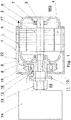
- Fig. 1 shows an air-cooled electric machine 1 of the subject type in partially cut form.
- the electric machine 1 shows a rotatably connected to a rotor shaft 2 rotor 3, a stator 4 arranged therein with axial cooling channels 5 and arranged on the drive side AS bearing plate 8 with a bearing 6 therein for rotatably receiving the rotor shaft 2 and one on the non-drive side NAS of the machine 1 arranged bearing plate 9 with the bearing 7 for rotatably receiving the rotor shaft 2.
- a clutch 11 is provided for connection to a corresponding gear 14.
- the clutch 11 includes a machine-side coupling part 12 and a transmission-side coupling part 13, which are connected to each other, for example via corresponding teeth, such as in a curved-tooth coupling, detachably.
- a fan 15 for guiding the cooling air L through the axial cooling channels 5 is connected.
- the fan 15 is arranged on the drive side AS of the machine 1 and integrated in the coupling 11.
- the cooling air L passes through the air inlets 16 on the drive side AS of the electric machine 1 through the axial cooling channels 5 in the stator 4 to corresponding air outlets 17 on the non-drive side NAS of the electric machine 1.
- the axial Length of the electric machine 1 is not increased by the fan 15, which is why smaller electric machines 1 can be made at the same power or identical electric machines 1 with higher performance over conventional electric machines 1.
- the fan 15 can be arranged on the machine-side coupling part 12, for example, be pressed.
- the area of the fan 15 may be surrounded by a housing 22, whereby the area of the fan 15 is protected from contamination.
- mechanical or magnetic filters can be arranged at the air inlets, which remove particles from the cooling air and prevent deposits in the cooling channels of the electric machine 1.
- Fig. 2 shows a variant in which the fan 15 is arranged via corresponding screws 18 on the machine-side coupling part 12. Furthermore, the fan 15, a groove 26 for the Use of balancing weights.
- the fan 15 is preferably formed of steel or aluminum or an aluminum alloy and is possibly produced together with the machine-side coupling part 12, preferably by casting.
- Fig. 4 shows a part of an air-cooled electric machine 1 in a sectional view, wherein elements 19 for guiding the cooling air L in the region of the air inlet 16 and on the inside of the housing 22 are arranged.
- the guide elements 19 are made in one piece with the housing or drive-side end plate 8.
- a further fan 21 is arranged for cooling the transmission 14 on the transmission-side coupling part 13.
- This further fan 21 can in turn be pressed onto the transmission-side coupling part 13 or connected by appropriate screws (not shown).
- cooling fins 20 may be provided to improve the cooling effect.
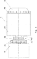
- FIG. 6 and 7 show a further embodiment of an electric machine 1, wherein on the housing 22 in the region of the axial cooling channels 5 of the stator 4 additional cooling fins 23 are arranged. These cooling ribs 23 are preferably produced in a casting process with the housing 22 of the electric machine 1.
- Fig. 8 shows a further embodiment of an inventively designed air-cooled electric machine 1 with two drive side AS arranged fans 15, 21.
- the blades 25 of the other fan 21 are curved, which is advantageous for electrical machines 1 with only one direction of rotation.
- FIG. 10 a further embodiment of a portion of an electric machine 1 in the sectional view, in which on the drive side AS between the drive-side bearing plate 8 and the rotor shaft 2 and the motor-side coupling part 12, a labyrinth seal 25 is arranged.
- the bearing 6 With the help of the machine-side coupling part 12, the bearing 6 is axially fixed on the drive side AS and prevents turning of the bearing inner ring.
Landscapes
- Engineering & Computer Science (AREA)
- Power Engineering (AREA)
- General Engineering & Computer Science (AREA)
- Mechanical Engineering (AREA)
- Motor Or Generator Cooling System (AREA)
- Motor Or Generator Frames (AREA)
Abstract
Die Erfindung betrifft eine luftgekühlte elektrische Maschine (1) mit einem mit einer Rotorwelle (2) drehfest verbundenen Rotor (3), einem Stator (4) mit axial angeordneten Kühlkanälen (5), an der Antriebsseite (AS) und Nichtantriebsseite (NAS) der Maschine (1) angeordneten Lagerschilde (8, 9) enthaltend die Lager (6, 7) zur drehbaren Aufnahme der Rotorwelle (2), einer am antriebsseitigen Ende (10) der Welle (2) angeordneten Kupplung (11) mit einem maschinenseitigen Kupplungsteil (12) und einem getriebeseitigen Kupplungsteil (13) zur Verbindung mit einem Getriebe (14), und mit einem mit der Rotorwelle (2) verbundenen Lüfter (15) zur Führung der Kühlluft durch die axialen Kühlkanäle (5). Zur Erzielung einer kompakteren Bauweise und eines verbesserten Kühlwirkung ist der Lüfter (15) an der Antriebsseite (AS) der Maschine (1) angeordnet und in der Kupplung (11) integriert, sodass die Kühlluft (L) von einem Lufteinlass (16) an der Antriebsseite (AS) durch die axialen Kühlkanäle (5) zu einem Luftauslass (17) an der Nichtantriebsseite (NAS) führbar ist.The invention relates to an air - cooled electric machine (1) having a rotor (3) connected in a rotationally fixed manner to a rotor shaft (2), a stator (4) with axially arranged cooling channels (5) on the drive side (AS) and non - drive side (NAS) Machine (1) arranged bearing plates (8, 9) comprising the bearings (6, 7) for rotatably receiving the rotor shaft (2), one at the drive end (10) of the shaft (2) arranged clutch (11) with a machine-side coupling part ( 12) and a transmission-side coupling part (13) for connection to a transmission (14), and with a with the rotor shaft (2) connected fan (15) for guiding the cooling air through the axial cooling channels (5). To achieve a more compact design and improved cooling effect of the fan (15) on the drive side (AS) of the machine (1) is arranged and integrated in the clutch (11), so that the cooling air (L) from an air inlet (16) on the Drive side (AS) through the axial cooling channels (5) to an air outlet (17) on the non-drive side (NAS) is feasible.
Description
Die Erfindung betrifft eine luftgekühlte elektrische Maschine mit einem mit einer Rotorwelle drehfest verbundenen Rotor, einem Stator mit axial angeordneten Kühlkanälen, an der Antriebsseite und Nichtantriebsseite der Maschine angeordneten Lagerschilde enthaltend die Lager zur drehbaren Aufnahme der Rotorwelle, einer am antriebsseitigen Ende der Welle angeordneten Kupplung mit einem maschinenseitigen Kupplungsteil und einem getriebeseitigen Kupplungsteil zur Verbindung mit einem Getriebe, und mit einem mit der Rotorwelle verbundenen Lüfter zur Führung der Kühlluft durch die axialen Kühlkanäle.The invention relates to an air-cooled electric machine having a rotatably connected to a rotor shaft rotor, a stator with axially disposed cooling channels, arranged on the drive side and non-drive side of the machine end shields containing the bearings for rotatably receiving the rotor shaft, arranged at the drive end of the shaft coupling a machine-side coupling part and a transmission-side coupling part for connection to a transmission, and with a fan connected to the rotor shaft for guiding the cooling air through the axial cooling channels.
Üblicherweise befindet sich bei luftgekühlten elektrischen Maschinen an der Nichtantriebsseite der Maschine ein Lüfter, der mit der Rotorwelle drehfest verbunden ist, um im Betrieb der elektrischen Maschine Kühlluft durch axial angeordnete Kühlkanäle im Stator und allenfalls Rotor zu leiten und die entstandene Wärme abzuführen. Beispielsweise beschreibt die
Durch den an der Nichtantriebsseite angeordneten Lüfter wird die axiale Länge des Antriebs vergrößert, wodurch der Platzbedarf für die elektrische Maschine steigt. Darüber hinaus ist die Kühlwirkung bei einer elektrischen Maschine mit nichtantriebsseitig angeordnetem Lüfter an der Antriebsseite verschlechtert.By arranged on the non-drive side fan the axial length of the drive is increased, whereby the space required for the electric machine increases. In addition, the cooling effect is deteriorated in an electric machine with non-drive side fan arranged on the drive side.
Die Aufgabe der vorliegenden Erfindung besteht daher in der Schaffung einer oben genannten luftgekühlten elektrischen Maschine mit geringerem Platzbedarf bzw. höherer Leistung bei gleicher Baugröße und zumindest gleicher Kühlwirkung gegenüber herkömmlichen elektrischen Maschinen.The object of the present invention is therefore to provide an above-mentioned air-cooled electric machine with less space or higher performance with the same size and at least the same cooling effect compared to conventional electrical machines.
Gelöst wird die erfindungsgemäße Aufgabe dadurch, dass der Lüfter an der Antriebsseite der Maschine angeordnet und in der Kupplung integriert ist, sodass die Kühlluft von einem Lufteinlass an der Antriebsseite durch die axialen Kühlkanäle zu einem Luftauslass an der Nichtantriebsseite führbar ist. Durch die erfindungsgemäße Anordnung des Lüfters an der Antriebsseite der Maschine und Integration in der Kupplung kann die axiale Länge der elektrischen Maschine reduziert werden bzw. die Leistung der elektrischen Maschine bei gleicher Baugröße gegenüber herkömmlichen luftgekühlten elektrischen Maschinen erhöht werden. Dadurch, dass die Rotorwelle gegenüber herkömmlichen elektrischen Maschinen kürzer ausgeführt werden kann, resultiert auch eine entsprechende Massenreduktion. Durch den antriebsseitig angeordneten Lüfter ist die Kühlwirkung des Lagers an der Antriebsseite der elektrischen Maschine gegenüber der Kühlwirkung an der Nichtantriebsseite verbessert. Derartige platzsparende luftgekühlte elektrische Maschinen eignen sich insbesondere für die Anwendung als Antriebsmaschine bei Schienenfahrzeugen, insbesondere Straßenbahnen.The object of the invention is achieved in that the fan is arranged on the drive side of the machine and integrated in the clutch, so that the cooling air can be guided from an air inlet on the drive side through the axial cooling channels to an air outlet on the non-drive side. The inventive arrangement of the fan on the drive side of the machine and integration in the coupling, the axial length of the electric machine can be reduced or the performance of be increased electrical machine with the same size compared to conventional air-cooled electrical machines. The fact that the rotor shaft can be made shorter than conventional electric machines, also results in a corresponding reduction in mass. By the fan arranged on the drive side, the cooling effect of the bearing on the drive side of the electric machine with respect to the cooling effect on the non-drive side is improved. Such space-saving air-cooled electrical machines are particularly suitable for use as a drive machine in rail vehicles, in particular trams.
Vorteilhafterweise ist der Lüfter am maschinenseitigen Kupplungsteil angeordnet. Durch eine derartige Konstruktion wird die axiale Länge der elektrischen Maschine durch den Lüfter nicht vergrößert. Der Lüfter kann am maschinenseitigen Kupplungsteil oder der Rotorwelle in diesem Bereich aufgepresst oder über entsprechende Schrauben verbunden werden.Advantageously, the fan is arranged on the machine-side coupling part. By such a construction, the axial length of the electric machine is not increased by the fan. The fan can be pressed on the machine-side coupling part or the rotor shaft in this area or connected via appropriate screws.
Ebenso kann der Lüfter mit dem maschinenseitigen Kupplungsteil einstückig hergestellt sein. Durch eine derartige Integration des Lüfters in der Kupplung wird der Montageaufwand entsprechend reduziert.Likewise, the fan can be made in one piece with the machine-side coupling part. Such an integration of the fan in the coupling of the installation effort is reduced accordingly.
Wenn Elemente zum Leiten der Kühlluft vorgesehen sind, kann die Kühlwirkung weiter verbessert werden, indem die Kühlluft gezielt über die zu kühlenden Bereiche der elektrischen Maschine geleitet wird.If elements for guiding the cooling air are provided, the cooling effect can be further improved by directing the cooling air over the areas of the electric machine to be cooled.
Gemäß einem Merkmal der Erfindung sind Leitelemente im Bereich des Lufteinlasses angeordnet. Durch derartige Luftleitelemente im Bereich des Lufteinlasses kann die Kühlluft gezielt dem antriebsseitig angeordneten Lüfter zugeführt werden, wodurch Turbulenzen vermieden und die Effizienz der Kühlung verbessert werden kann.According to a feature of the invention, guide elements are arranged in the region of the air inlet. By such air guide elements in the region of the air inlet, the cooling air can be selectively supplied to the drive side arranged fan, whereby turbulence can be avoided and the efficiency of the cooling can be improved.
Die Leitelemente können einstückig mit dem antriebsseitigen Lagerschild hergestellt sein, wodurch der Montageaufwand reduziert werden kann.The guide elements can be made in one piece with the drive-side bearing plate, whereby the assembly cost can be reduced.
Am nichtantriebsseitigen Lagerschild können Kühlrippen angeordnet sein. Somit kann auch an der Nichtantriebsseite der elektrischen Maschine eine verbesserte Kühlwirkung erzielt werden.On the non-drive end shield cooling fins can be arranged. Thus, an improved cooling effect can also be achieved on the non-drive side of the electric machine.
Gegebenenfalls ist am getriebeseitigen Kupplungsteil ein weiterer Lüfter zum Kühlen des Getriebes angeordnet. Auch dieser weitere Lüfter kann auf dem getriebeseitigen Kupplungsteil oder der Rotorwelle aufgepresst oder mit entsprechenden Schrauben verbunden sein. Darüber hinaus ist auch eine einstückige Herstellung des getriebeseitigen Kupplungsteils mit dem weiteren Lüfter möglich.Optionally, a further fan for cooling the transmission is arranged on the transmission-side coupling part. Also, this further fan can be pressed onto the transmission-side coupling part or the rotor shaft or connected with appropriate screws. In addition, a one-piece production of the transmission-side coupling part with the other fan is possible.
Vorteilhafterweise ist die elektrische Maschine von einem Gehäuse umgeben. Durch ein derartiges Gehäuse wird die elektrische Maschine vor Verschmutzung geschützt. Zum Verhindern des Ansaugens schmutziger Kühlluft können an den Lufteinlässen mechanische oder auch magnetische Filter angeordnet sein, welche Partikel aus der Kühlluft entfernen und ein Anlagern in den Kühlkanälen der elektrischen Maschine verhindern.Advantageously, the electric machine is surrounded by a housing. By such a housing, the electrical machine is protected from contamination. To prevent the suction of dirty cooling air can be arranged on the air inlets mechanical or magnetic filter, which remove particles from the cooling air and prevent them from accumulating in the cooling channels of the electric machine.
Der Stator kann im Bereich der axialen Kühlkanäle Kühlrippen aufweisen. Durch derartig gestaltete Kühlrippen, welche auch im oben genannten Gehäuse integriert sein können, wird das Abführen der Wärme weiter verbessert.The stator may have cooling ribs in the region of the axial cooling channels. By thus designed cooling fins, which may also be integrated in the above-mentioned housing, the dissipation of heat is further improved.
Der Lüfter und allenfalls der weitere Lüfter kann durch einen Radiallüfter gebildet sein. Derartige Radialbelüfter sind für den gegenständlichen Anwendungsfall, bei dem die Kühlluft axial durch die Lufteinlässe eintritt und danach radial in Richtung der im Stator angeordneten Kanäle weitergeführt wird, besonders vorteilhaft. Alternativ dazu ist jedoch auch die Anwendung von Axiallüftern denkbar.The fan and possibly the other fan can be formed by a radial fan. Such radial aerators are for the objective application, in which the cooling air enters axially through the air inlets and is then continued radially in the direction of the channels arranged in the stator, particularly advantageous. Alternatively, however, the use of axial fans is conceivable.
Der Lüfter und allenfalls der weitere Lüfter kann aus Stahl oder Aluminium oder einer Aluminiumlegierung gebildet werden. Die Verwendung von Metallen ist hinsichtlich der mechanischen Robustheit vorzuziehen, wobei Aluminium oder Aluminiumlegierung im Bezug auf das Gewicht Stahl vorzuziehen ist. Unter der Voraussetzung entsprechender Temperaturbeständigkeit sind auch Materialvarianten auf Kunststoffbasis beziehungsweise Verbundwerkstoffe auf Kunststoffbasis, welche Temperaturen über 100° Celsius standhalten, für die Herstellung der Lüfter denkbar. Idealerweise werden die Lüfter durch Gießen hergestellt.The fan and possibly the other fan can be made of steel or aluminum or an aluminum alloy. The use of metals is preferable in terms of mechanical ruggedness, with aluminum or aluminum alloy being preferable to steel in terms of weight. On the condition of appropriate temperature resistance and material variants are based on plastic or Plastic-based composites, which withstand temperatures in excess of 100 ° Celsius, are conceivable for the production of the fans. Ideally, the fans are made by casting.
Gemäß einem weiteren Merkmal der Erfindung weist der Lüfter und allenfalls der weitere Lüfter gekrümmte Schaufeln auf. Eine derartige Ausführungsvariante ist bei elektrischen Maschinen mit nur einer Drehrichtung von Vorteil. Wird die elektrische Maschine in beiden Drehrichtungen verwendet, werden gerade Schaufeln vorzuziehen sein, um bei beiden Drehrichtungen eine entsprechende Kühlwirkung erzielen zu können.According to a further feature of the invention, the fan and possibly the further fan on curved blades. Such a variant is advantageous in electric machines with only one direction of rotation. If the electric machine is used in both directions of rotation, it will be preferable to use shovels in order to be able to achieve a corresponding cooling effect in both directions of rotation.
Vorteilhafterweise sind der Lüfter und der maschinenseitige Kupplungsteil der Kupplung sowie der weitere Lüfter und der getriebeseitige Kupplungsteil der Kupplung gemeinsam gewuchtet. Durch diese Maßnahme können Schwingungen der elektrischen Maschine und in der Folge auch Geräuschentwicklungen reduziert werden. Zu diesem Zweck können der Lüfter und allenfalls der weitere Lüfter eine entsprechende Nut für den Einsatz von Wuchtgewichten aufweisen.Advantageously, the fan and the machine-side coupling part of the clutch and the other fan and the transmission-side coupling part of the clutch are balanced together. By this measure, vibrations of the electric machine and, as a result, noise developments can be reduced. For this purpose, the fan and possibly the other fan may have a corresponding groove for the use of balancing weights.
Die Kupplung kann beispielsweise durch eine Bogenzahn-Kupplung gebildet sein. Bei einer Bogenzahn-Kupplung wird der maschinenseitige Kupplungsteil und der getriebeseitige Kupplungsteil durch ineinandergreifende Verzahnung lösbar miteinander verbunden. Andere Ausführungsvarianten von Kupplungen sind natürlich ebenfalls denkbar (beispielsweise Membrankupplungen, Ganzstahlkupplungen, stirnverzahnte Kupplungen, Klauenkupplungen, elastische Bolzenkupplungen, elastische Zahnkranzkupplungen, Hohlwellenkupplungen, Keilpaketkupplungen). Die Kupplungen können stromisoliert ausgeführt werden. Weiters können die Kupplungen mit einen Rutschelement ausgestattet werden.The coupling may be formed for example by a curved tooth coupling. In a curved tooth coupling of the machine-side coupling part and the transmission-side coupling part is releasably connected to each other by interlocking teeth. Other variants of clutches are of course also conceivable (for example, membrane couplings, all-steel couplings, front-toothed couplings, dog clutches, elastic pin couplings, elastic sprocket couplings, hollow shaft couplings, Keilpaketkupplungen). The couplings can be carried out in a current-isolated manner. Furthermore, the couplings can be equipped with a sliding element.
An der Antriebsseite ist zwischen Lagerschild und maschinenseitigem Kupplungsteil vorzugsweise eine Labyrinthdichtung angeordnet. Durch eine derartige Labyrinthdichtung kann eine berührungsfreie Abdichtung der rotierenden Rotorwelle gegenüber den stehenden Teilen der elektrischen Maschine erreicht werden. Je nach Ausführungsform können entsprechend viele Labyrinthstufen in der Labyrinthdichtung vorgesehen sein. Die rotierende Labyrinthdichtung kann wie folgt ausgeführt werden:
- die Labyrinthstufen werden in einem eigenen Bauteil integriert, welches auf der Rotorwelle montiert ist;
- die Labyrinthstufen als Teil des maschinenseitigen Kupplungsteils;
- die Labyrinthstufen als Teil des Lüfters.
- the labyrinth stages are integrated in a separate component, which is mounted on the rotor shaft;
- the labyrinth stages as part of the machine-side coupling part;
- the labyrinth stages as part of the fan.
Die Erfindung wird anhand der beigefügten Zeichnungen näher erläutert. Darin zeigen:
-
Fig. 1 eine teilweise geschnittene Ausführungsform einer erfindungsgemäß ausgebildeten luftgekühlten elektrischen Maschine; -
Fig. 2 eine Variante gegenüberFig. 1 , bei der der Lüfter über Schrauben mit dem maschinenseitigen Kupplungsteil verbunden ist; -
Fig. 3 eine Variante eines Lüfters, der einstückig mit dem maschinenseitigen Kupplungsteil hergestellt ist; -
Fig. 4 optional angeordnete Leitelemente im Bereich des Lufteinlasses und antriebsseitigen Lagerschilds; -
Fig. 5 eine Ansicht auf eine luftgekühlte elektrische Maschine mit einem weiteren Lüfter zum Kühlen des Getriebes; -
Fig. 6 und 7 eine Ausführungsform der luftgekühlten elektrischen Maschine mit Kühlrippen am Stator in Draufsicht und Seitenansicht; -
Fig. 8 eine Ausführungsvariante einer elektrischen Maschine mit zwei antriebsseitig angeordneten Lüftern; -
Fig. 9 ein Schnittbild entlang der Schnittlinie IX-IX derFig. 8 ; und -
Fig. 10 eine geschnittene Teilansicht der Antriebsseite einer luftgekühlten elektrischen Maschine der gegenständlichen Art mit einer Labyrinthdichtung im Bereich des antriebsseitigen Lagerschilds.
-
Fig. 1 a partially sectioned embodiment of an inventively designed air-cooled electric machine; -
Fig. 2 a variant oppositeFig. 1 in which the fan is connected via screws to the machine-side coupling part; -
Fig. 3 a variant of a fan, which is made in one piece with the machine-side coupling part; -
Fig. 4 optionally arranged guide elements in the region of the air inlet and drive-side end shield; -
Fig. 5 a view of an air-cooled electric machine with another fan for cooling the transmission; -
6 and 7 an embodiment of the air-cooled electric machine with cooling fins on the stator in plan view and side view; -
Fig. 8 an embodiment of an electric machine with two fans arranged on the drive side; -
Fig. 9 a sectional view along the section line IX-IX ofFig. 8 ; and -
Fig. 10 a sectional partial view of the drive side of an air-cooled electric machine of the subject type with a labyrinth seal in the region of the drive-side end shield.
Weiters ist, wie in
Der Lüfter 15 ist vorzugsweise aus Stahl oder Aluminium oder einer Aluminiumlegierung gebildet und wird allenfalls zusammen mit dem maschinenseitigen Kupplungsteil 12, vorzugsweise durch Gießen, hergestellt.The
Bei der Ausführungsvariante einer luftgekühlten elektrischen Maschine 1 gemäß
Schließlich zeigt
Claims (15)
Priority Applications (1)
| Application Number | Priority Date | Filing Date | Title |
|---|---|---|---|
| PL17153168T PL3200327T3 (en) | 2016-01-29 | 2017-01-26 | Air-cooled electric machine |
Applications Claiming Priority (1)
| Application Number | Priority Date | Filing Date | Title |
|---|---|---|---|
| ATA50051/2016A AT518218B1 (en) | 2016-01-29 | 2016-01-29 | Air-cooled electric machine |
Publications (2)
| Publication Number | Publication Date |
|---|---|
| EP3200327A1 true EP3200327A1 (en) | 2017-08-02 |
| EP3200327B1 EP3200327B1 (en) | 2020-06-03 |
Family
ID=57906516
Family Applications (1)
| Application Number | Title | Priority Date | Filing Date |
|---|---|---|---|
| EP17153168.4A Active EP3200327B1 (en) | 2016-01-29 | 2017-01-26 | Air-cooled electric machine |
Country Status (4)
| Country | Link |
|---|---|
| EP (1) | EP3200327B1 (en) |
| AT (1) | AT518218B1 (en) |
| ES (1) | ES2809102T3 (en) |
| PL (1) | PL3200327T3 (en) |
Cited By (3)
| Publication number | Priority date | Publication date | Assignee | Title |
|---|---|---|---|---|
| CN111740544A (en) * | 2020-08-25 | 2020-10-02 | 南京莉上网络科技有限公司 | Heat dissipation motor that heat was adjusted can carry out |
| WO2021114451A1 (en) * | 2019-12-09 | 2021-06-17 | 深圳市中悦机电科技有限公司 | Heat dissipation structure of permanent magnet motor |
| CN114645909A (en) * | 2022-04-14 | 2022-06-21 | 深圳市联兆电子有限公司 | New energy automobile power coupling excess temperature protection device |
Citations (5)
| Publication number | Priority date | Publication date | Assignee | Title |
|---|---|---|---|---|
| AT154719B (en) * | 1936-05-28 | 1938-10-25 | Bbc Ag Oesterr | Drive for electrically operated vehicles, in particular for light rail vehicles and road vehicles. |
| CH444949A (en) * | 1965-11-09 | 1967-10-15 | Bosch Gmbh Robert | Collector motor that can be operated with alternating current |
| US3622821A (en) * | 1970-03-27 | 1971-11-23 | Black & Decker Mfg Co | Double-insulated motor armature |
| DE2548058A1 (en) * | 1975-10-27 | 1977-04-28 | Thyssen Industrie | DOUBLE AXLE DRIVE FOR RAIL VEHICLES |
| US20040150270A1 (en) * | 2002-11-25 | 2004-08-05 | Takashi Nagayama | Fully enclosed type motor with outer fans |
Family Cites Families (3)
| Publication number | Priority date | Publication date | Assignee | Title |
|---|---|---|---|---|
| US6695581B2 (en) * | 2001-12-19 | 2004-02-24 | Mcmillan Electric Company | Combination fan-flywheel-pulley assembly and method of forming |
| US7459817B2 (en) * | 2006-08-15 | 2008-12-02 | Bombardier Transportation Gmbh | Semi-enclosed AC motor |
| DE102008023712A1 (en) * | 2008-05-15 | 2009-11-19 | Bayerische Motoren Werke Aktiengesellschaft | Drive train for hybrid vehicles, comprises combustion engine, which has crankshaft, transmission, which comprises transmission input, and coupling unit arranged between crankshaft and transmission input |
-
2016
- 2016-01-29 AT ATA50051/2016A patent/AT518218B1/en active
-
2017
- 2017-01-26 EP EP17153168.4A patent/EP3200327B1/en active Active
- 2017-01-26 PL PL17153168T patent/PL3200327T3/en unknown
- 2017-01-26 ES ES17153168T patent/ES2809102T3/en active Active
Patent Citations (5)
| Publication number | Priority date | Publication date | Assignee | Title |
|---|---|---|---|---|
| AT154719B (en) * | 1936-05-28 | 1938-10-25 | Bbc Ag Oesterr | Drive for electrically operated vehicles, in particular for light rail vehicles and road vehicles. |
| CH444949A (en) * | 1965-11-09 | 1967-10-15 | Bosch Gmbh Robert | Collector motor that can be operated with alternating current |
| US3622821A (en) * | 1970-03-27 | 1971-11-23 | Black & Decker Mfg Co | Double-insulated motor armature |
| DE2548058A1 (en) * | 1975-10-27 | 1977-04-28 | Thyssen Industrie | DOUBLE AXLE DRIVE FOR RAIL VEHICLES |
| US20040150270A1 (en) * | 2002-11-25 | 2004-08-05 | Takashi Nagayama | Fully enclosed type motor with outer fans |
Cited By (5)
| Publication number | Priority date | Publication date | Assignee | Title |
|---|---|---|---|---|
| WO2021114451A1 (en) * | 2019-12-09 | 2021-06-17 | 深圳市中悦机电科技有限公司 | Heat dissipation structure of permanent magnet motor |
| CN111740544A (en) * | 2020-08-25 | 2020-10-02 | 南京莉上网络科技有限公司 | Heat dissipation motor that heat was adjusted can carry out |
| CN111740544B (en) * | 2020-08-25 | 2021-01-22 | 浙江福霸机电有限公司 | Heat dissipation motor that heat was adjusted can carry out |
| CN114645909A (en) * | 2022-04-14 | 2022-06-21 | 深圳市联兆电子有限公司 | New energy automobile power coupling excess temperature protection device |
| CN114645909B (en) * | 2022-04-14 | 2023-11-03 | 深圳市联兆电子有限公司 | Over-temperature protection device for power coupler of new energy automobile |
Also Published As
| Publication number | Publication date |
|---|---|
| EP3200327B1 (en) | 2020-06-03 |
| PL3200327T3 (en) | 2020-11-16 |
| AT518218B1 (en) | 2017-12-15 |
| ES2809102T3 (en) | 2021-03-03 |
| AT518218A1 (en) | 2017-08-15 |
Similar Documents
| Publication | Publication Date | Title |
|---|---|---|
| EP2109207B1 (en) | Liquid cooled electric machine and process for cooling an electric machine | |
| EP1703618B1 (en) | Air-cooled electric motor | |
| DE112014002014B4 (en) | Hybrid module for motor vehicle | |
| EP3878080A1 (en) | Electric machine having a fluid cooling device | |
| WO2011101224A1 (en) | Electrical drive unit | |
| EP3200327B1 (en) | Air-cooled electric machine | |
| EP2191940A1 (en) | Electrical tool | |
| DE112012000043T5 (en) | generator motor | |
| DE102016210930B4 (en) | Electric machine | |
| DE102020106341A1 (en) | Electric machine | |
| DE102013020324A1 (en) | Electric machine i.e. asynchronous machine, for use in drive train of e.g. electric vehicle, has duct element comprising channel running diagonal to axial direction of shaft for guiding coolant from channel of shaft to environment of shaft | |
| EP3114756A1 (en) | Electric machine having a hollow shaft through which cooling fluid flows | |
| EP0688090B1 (en) | Motor cooling system | |
| EP3355444B1 (en) | Motor vehicle and rotor for an electric machine, an electric machine, in particular asynchronous machine for a motor vehicle | |
| DE102011087273B4 (en) | Electric machine | |
| WO2018029217A1 (en) | Electrical machine unit comprising a slip ring arrangement exposed to an air current | |
| DE102016004936B4 (en) | Electric machine | |
| EP2086091A2 (en) | Electric air-cooled machine | |
| DE102016009248A1 (en) | Electric machine and machine-gear arrangement with such an electric machine | |
| DE102013203911B3 (en) | Electric machine, has stator portion and rotor-side part flowing around winding head and omitting over outlet in housing, where vicinity of machine is delivered into orifice and rotor-side part is guided along direction of axis | |
| WO2015197158A1 (en) | Drive | |
| EP3211761B1 (en) | Air cooled electric machine | |
| DE102019207326A1 (en) | Cooling arrangement for the rotor of an electrical machine and electrical machine | |
| EP2920867A2 (en) | Electric motor with a stator | |
| DE102020107376B4 (en) | Cooling device with a distributor ring that can be driven in rotation by a coolant flow; as well as electric drive unit |
Legal Events
| Date | Code | Title | Description |
|---|---|---|---|
| PUAI | Public reference made under article 153(3) epc to a published international application that has entered the european phase |
Free format text: ORIGINAL CODE: 0009012 |
|
| STAA | Information on the status of an ep patent application or granted ep patent |
Free format text: STATUS: THE APPLICATION HAS BEEN PUBLISHED |
|
| AK | Designated contracting states |
Kind code of ref document: A1 Designated state(s): AL AT BE BG CH CY CZ DE DK EE ES FI FR GB GR HR HU IE IS IT LI LT LU LV MC MK MT NL NO PL PT RO RS SE SI SK SM TR |
|
| AX | Request for extension of the european patent |
Extension state: BA ME |
|
| STAA | Information on the status of an ep patent application or granted ep patent |
Free format text: STATUS: REQUEST FOR EXAMINATION WAS MADE |
|
| 17P | Request for examination filed |
Effective date: 20180122 |
|
| RBV | Designated contracting states (corrected) |
Designated state(s): AL AT BE BG CH CY CZ DE DK EE ES FI FR GB GR HR HU IE IS IT LI LT LU LV MC MK MT NL NO PL PT RO RS SE SI SK SM TR |
|
| STAA | Information on the status of an ep patent application or granted ep patent |
Free format text: STATUS: EXAMINATION IS IN PROGRESS |
|
| 17Q | First examination report despatched |
Effective date: 20180411 |
|
| GRAP | Despatch of communication of intention to grant a patent |
Free format text: ORIGINAL CODE: EPIDOSNIGR1 |
|
| STAA | Information on the status of an ep patent application or granted ep patent |
Free format text: STATUS: GRANT OF PATENT IS INTENDED |
|
| RIC1 | Information provided on ipc code assigned before grant |
Ipc: H02K 7/116 20060101ALN20191213BHEP Ipc: F16D 13/76 20060101ALN20191213BHEP Ipc: H02K 1/20 20060101ALN20191213BHEP Ipc: H02K 9/06 20060101ALI20191213BHEP Ipc: B61C 9/48 20060101ALN20191213BHEP Ipc: H02K 9/16 20060101ALI20191213BHEP Ipc: F16D 3/18 20060101ALI20191213BHEP Ipc: H02K 7/00 20060101AFI20191213BHEP |
|
| INTG | Intention to grant announced |
Effective date: 20200117 |
|
| GRAS | Grant fee paid |
Free format text: ORIGINAL CODE: EPIDOSNIGR3 |
|
| GRAA | (expected) grant |
Free format text: ORIGINAL CODE: 0009210 |
|
| STAA | Information on the status of an ep patent application or granted ep patent |
Free format text: STATUS: THE PATENT HAS BEEN GRANTED |
|
| AK | Designated contracting states |
Kind code of ref document: B1 Designated state(s): AL AT BE BG CH CY CZ DE DK EE ES FI FR GB GR HR HU IE IS IT LI LT LU LV MC MK MT NL NO PL PT RO RS SE SI SK SM TR |
|
| REG | Reference to a national code |
Ref country code: GB Ref legal event code: FG4D Free format text: NOT ENGLISH |
|
| REG | Reference to a national code |
Ref country code: AT Ref legal event code: REF Ref document number: 1278045 Country of ref document: AT Kind code of ref document: T Effective date: 20200615 Ref country code: CH Ref legal event code: EP |
|
| REG | Reference to a national code |
Ref country code: DE Ref legal event code: R096 Ref document number: 502017005503 Country of ref document: DE |
|
| REG | Reference to a national code |
Ref country code: CH Ref legal event code: NV Representative=s name: KELLER AND PARTNER PATENTANWAELTE AG, CH |
|
| REG | Reference to a national code |
Ref country code: SE Ref legal event code: TRGR |
|
| REG | Reference to a national code |
Ref country code: CH Ref legal event code: PFA Owner name: TRAKTIONSSYSTEME AUSTRIA GMBH, AT Free format text: FORMER OWNER: TRAKTIONSSYSTEME AUSTRIA GMBH, AT |
|
| REG | Reference to a national code |
Ref country code: LT Ref legal event code: MG4D |
|
| PG25 | Lapsed in a contracting state [announced via postgrant information from national office to epo] |
Ref country code: NO Free format text: LAPSE BECAUSE OF FAILURE TO SUBMIT A TRANSLATION OF THE DESCRIPTION OR TO PAY THE FEE WITHIN THE PRESCRIBED TIME-LIMIT Effective date: 20200903 Ref country code: GR Free format text: LAPSE BECAUSE OF FAILURE TO SUBMIT A TRANSLATION OF THE DESCRIPTION OR TO PAY THE FEE WITHIN THE PRESCRIBED TIME-LIMIT Effective date: 20200904 Ref country code: FI Free format text: LAPSE BECAUSE OF FAILURE TO SUBMIT A TRANSLATION OF THE DESCRIPTION OR TO PAY THE FEE WITHIN THE PRESCRIBED TIME-LIMIT Effective date: 20200603 Ref country code: LT Free format text: LAPSE BECAUSE OF FAILURE TO SUBMIT A TRANSLATION OF THE DESCRIPTION OR TO PAY THE FEE WITHIN THE PRESCRIBED TIME-LIMIT Effective date: 20200603 |
|
| REG | Reference to a national code |
Ref country code: NL Ref legal event code: MP Effective date: 20200603 |
|
| PG25 | Lapsed in a contracting state [announced via postgrant information from national office to epo] |
Ref country code: LV Free format text: LAPSE BECAUSE OF FAILURE TO SUBMIT A TRANSLATION OF THE DESCRIPTION OR TO PAY THE FEE WITHIN THE PRESCRIBED TIME-LIMIT Effective date: 20200603 Ref country code: BG Free format text: LAPSE BECAUSE OF FAILURE TO SUBMIT A TRANSLATION OF THE DESCRIPTION OR TO PAY THE FEE WITHIN THE PRESCRIBED TIME-LIMIT Effective date: 20200903 Ref country code: RS Free format text: LAPSE BECAUSE OF FAILURE TO SUBMIT A TRANSLATION OF THE DESCRIPTION OR TO PAY THE FEE WITHIN THE PRESCRIBED TIME-LIMIT Effective date: 20200603 Ref country code: HR Free format text: LAPSE BECAUSE OF FAILURE TO SUBMIT A TRANSLATION OF THE DESCRIPTION OR TO PAY THE FEE WITHIN THE PRESCRIBED TIME-LIMIT Effective date: 20200603 |
|
| PG25 | Lapsed in a contracting state [announced via postgrant information from national office to epo] |
Ref country code: NL Free format text: LAPSE BECAUSE OF FAILURE TO SUBMIT A TRANSLATION OF THE DESCRIPTION OR TO PAY THE FEE WITHIN THE PRESCRIBED TIME-LIMIT Effective date: 20200603 Ref country code: AL Free format text: LAPSE BECAUSE OF FAILURE TO SUBMIT A TRANSLATION OF THE DESCRIPTION OR TO PAY THE FEE WITHIN THE PRESCRIBED TIME-LIMIT Effective date: 20200603 |
|
| PG25 | Lapsed in a contracting state [announced via postgrant information from national office to epo] |
Ref country code: PT Free format text: LAPSE BECAUSE OF FAILURE TO SUBMIT A TRANSLATION OF THE DESCRIPTION OR TO PAY THE FEE WITHIN THE PRESCRIBED TIME-LIMIT Effective date: 20201006 Ref country code: SM Free format text: LAPSE BECAUSE OF FAILURE TO SUBMIT A TRANSLATION OF THE DESCRIPTION OR TO PAY THE FEE WITHIN THE PRESCRIBED TIME-LIMIT Effective date: 20200603 Ref country code: EE Free format text: LAPSE BECAUSE OF FAILURE TO SUBMIT A TRANSLATION OF THE DESCRIPTION OR TO PAY THE FEE WITHIN THE PRESCRIBED TIME-LIMIT Effective date: 20200603 Ref country code: RO Free format text: LAPSE BECAUSE OF FAILURE TO SUBMIT A TRANSLATION OF THE DESCRIPTION OR TO PAY THE FEE WITHIN THE PRESCRIBED TIME-LIMIT Effective date: 20200603 |
|
| PG25 | Lapsed in a contracting state [announced via postgrant information from national office to epo] |
Ref country code: IS Free format text: LAPSE BECAUSE OF FAILURE TO SUBMIT A TRANSLATION OF THE DESCRIPTION OR TO PAY THE FEE WITHIN THE PRESCRIBED TIME-LIMIT Effective date: 20201003 Ref country code: SK Free format text: LAPSE BECAUSE OF FAILURE TO SUBMIT A TRANSLATION OF THE DESCRIPTION OR TO PAY THE FEE WITHIN THE PRESCRIBED TIME-LIMIT Effective date: 20200603 |
|
| REG | Reference to a national code |
Ref country code: ES Ref legal event code: FG2A Ref document number: 2809102 Country of ref document: ES Kind code of ref document: T3 Effective date: 20210303 |
|
| REG | Reference to a national code |
Ref country code: DE Ref legal event code: R097 Ref document number: 502017005503 Country of ref document: DE |
|
| PLBE | No opposition filed within time limit |
Free format text: ORIGINAL CODE: 0009261 |
|
| STAA | Information on the status of an ep patent application or granted ep patent |
Free format text: STATUS: NO OPPOSITION FILED WITHIN TIME LIMIT |
|
| PG25 | Lapsed in a contracting state [announced via postgrant information from national office to epo] |
Ref country code: DK Free format text: LAPSE BECAUSE OF FAILURE TO SUBMIT A TRANSLATION OF THE DESCRIPTION OR TO PAY THE FEE WITHIN THE PRESCRIBED TIME-LIMIT Effective date: 20200603 |
|
| 26N | No opposition filed |
Effective date: 20210304 |
|
| PG25 | Lapsed in a contracting state [announced via postgrant information from national office to epo] |
Ref country code: SI Free format text: LAPSE BECAUSE OF FAILURE TO SUBMIT A TRANSLATION OF THE DESCRIPTION OR TO PAY THE FEE WITHIN THE PRESCRIBED TIME-LIMIT Effective date: 20200603 |
|
| PG25 | Lapsed in a contracting state [announced via postgrant information from national office to epo] |
Ref country code: MC Free format text: LAPSE BECAUSE OF FAILURE TO SUBMIT A TRANSLATION OF THE DESCRIPTION OR TO PAY THE FEE WITHIN THE PRESCRIBED TIME-LIMIT Effective date: 20200603 |
|
| PG25 | Lapsed in a contracting state [announced via postgrant information from national office to epo] |
Ref country code: LU Free format text: LAPSE BECAUSE OF NON-PAYMENT OF DUE FEES Effective date: 20210126 |
|
| REG | Reference to a national code |
Ref country code: BE Ref legal event code: MM Effective date: 20210131 |
|
| PG25 | Lapsed in a contracting state [announced via postgrant information from national office to epo] |
Ref country code: IE Free format text: LAPSE BECAUSE OF NON-PAYMENT OF DUE FEES Effective date: 20210126 |
|
| PGFP | Annual fee paid to national office [announced via postgrant information from national office to epo] |
Ref country code: SE Payment date: 20220125 Year of fee payment: 6 Ref country code: CZ Payment date: 20220118 Year of fee payment: 6 |
|
| PG25 | Lapsed in a contracting state [announced via postgrant information from national office to epo] |
Ref country code: BE Free format text: LAPSE BECAUSE OF NON-PAYMENT OF DUE FEES Effective date: 20210131 |
|
| REG | Reference to a national code |
Ref country code: AT Ref legal event code: MM01 Ref document number: 1278045 Country of ref document: AT Kind code of ref document: T Effective date: 20220126 |
|
| PG25 | Lapsed in a contracting state [announced via postgrant information from national office to epo] |
Ref country code: AT Free format text: LAPSE BECAUSE OF NON-PAYMENT OF DUE FEES Effective date: 20220126 |
|
| PG25 | Lapsed in a contracting state [announced via postgrant information from national office to epo] |
Ref country code: HU Free format text: LAPSE BECAUSE OF FAILURE TO SUBMIT A TRANSLATION OF THE DESCRIPTION OR TO PAY THE FEE WITHIN THE PRESCRIBED TIME-LIMIT; INVALID AB INITIO Effective date: 20170126 |
|
| P01 | Opt-out of the competence of the unified patent court (upc) registered |
Effective date: 20230522 |
|
| PG25 | Lapsed in a contracting state [announced via postgrant information from national office to epo] |
Ref country code: CY Free format text: LAPSE BECAUSE OF FAILURE TO SUBMIT A TRANSLATION OF THE DESCRIPTION OR TO PAY THE FEE WITHIN THE PRESCRIBED TIME-LIMIT Effective date: 20200603 |
|
| REG | Reference to a national code |
Ref country code: SE Ref legal event code: EUG |
|
| PG25 | Lapsed in a contracting state [announced via postgrant information from national office to epo] |
Ref country code: SE Free format text: LAPSE BECAUSE OF NON-PAYMENT OF DUE FEES Effective date: 20230127 Ref country code: CZ Free format text: LAPSE BECAUSE OF NON-PAYMENT OF DUE FEES Effective date: 20230126 |
|
| PGFP | Annual fee paid to national office [announced via postgrant information from national office to epo] |
Ref country code: ES Payment date: 20240216 Year of fee payment: 8 |
|
| PG25 | Lapsed in a contracting state [announced via postgrant information from national office to epo] |
Ref country code: MK Free format text: LAPSE BECAUSE OF FAILURE TO SUBMIT A TRANSLATION OF THE DESCRIPTION OR TO PAY THE FEE WITHIN THE PRESCRIBED TIME-LIMIT Effective date: 20200603 |
|
| PGFP | Annual fee paid to national office [announced via postgrant information from national office to epo] |
Ref country code: DE Payment date: 20240119 Year of fee payment: 8 Ref country code: GB Payment date: 20240124 Year of fee payment: 8 Ref country code: CH Payment date: 20240202 Year of fee payment: 8 |
|
| PGFP | Annual fee paid to national office [announced via postgrant information from national office to epo] |
Ref country code: PL Payment date: 20240116 Year of fee payment: 8 Ref country code: IT Payment date: 20240131 Year of fee payment: 8 Ref country code: FR Payment date: 20240123 Year of fee payment: 8 |