EP3200262B1 - Rectangular secondary battery - Google Patents
Rectangular secondary battery Download PDFInfo
- Publication number
- EP3200262B1 EP3200262B1 EP15843323.5A EP15843323A EP3200262B1 EP 3200262 B1 EP3200262 B1 EP 3200262B1 EP 15843323 A EP15843323 A EP 15843323A EP 3200262 B1 EP3200262 B1 EP 3200262B1
- Authority
- EP
- European Patent Office
- Prior art keywords
- joint
- collecting plate
- current collecting
- positive electrode
- thickness
- Prior art date
- Legal status (The legal status is an assumption and is not a legal conclusion. Google has not performed a legal analysis and makes no representation as to the accuracy of the status listed.)
- Active
Links
Images


Classifications
-
- H—ELECTRICITY
- H01—ELECTRIC ELEMENTS
- H01M—PROCESSES OR MEANS, e.g. BATTERIES, FOR THE DIRECT CONVERSION OF CHEMICAL ENERGY INTO ELECTRICAL ENERGY
- H01M10/00—Secondary cells; Manufacture thereof
- H01M10/05—Accumulators with non-aqueous electrolyte
- H01M10/058—Construction or manufacture
- H01M10/0587—Construction or manufacture of accumulators having only wound construction elements, i.e. wound positive electrodes, wound negative electrodes and wound separators
-
- H—ELECTRICITY
- H01—ELECTRIC ELEMENTS
- H01M—PROCESSES OR MEANS, e.g. BATTERIES, FOR THE DIRECT CONVERSION OF CHEMICAL ENERGY INTO ELECTRICAL ENERGY
- H01M10/00—Secondary cells; Manufacture thereof
- H01M10/05—Accumulators with non-aqueous electrolyte
- H01M10/052—Li-accumulators
- H01M10/0525—Rocking-chair batteries, i.e. batteries with lithium insertion or intercalation in both electrodes; Lithium-ion batteries
-
- H—ELECTRICITY
- H01—ELECTRIC ELEMENTS
- H01M—PROCESSES OR MEANS, e.g. BATTERIES, FOR THE DIRECT CONVERSION OF CHEMICAL ENERGY INTO ELECTRICAL ENERGY
- H01M50/00—Constructional details or processes of manufacture of the non-active parts of electrochemical cells other than fuel cells, e.g. hybrid cells
- H01M50/50—Current conducting connections for cells or batteries
- H01M50/531—Electrode connections inside a battery casing
- H01M50/533—Electrode connections inside a battery casing characterised by the shape of the leads or tabs
-
- H—ELECTRICITY
- H01—ELECTRIC ELEMENTS
- H01M—PROCESSES OR MEANS, e.g. BATTERIES, FOR THE DIRECT CONVERSION OF CHEMICAL ENERGY INTO ELECTRICAL ENERGY
- H01M50/00—Constructional details or processes of manufacture of the non-active parts of electrochemical cells other than fuel cells, e.g. hybrid cells
- H01M50/50—Current conducting connections for cells or batteries
- H01M50/531—Electrode connections inside a battery casing
- H01M50/534—Electrode connections inside a battery casing characterised by the material of the leads or tabs
-
- H—ELECTRICITY
- H01—ELECTRIC ELEMENTS
- H01M—PROCESSES OR MEANS, e.g. BATTERIES, FOR THE DIRECT CONVERSION OF CHEMICAL ENERGY INTO ELECTRICAL ENERGY
- H01M2220/00—Batteries for particular applications
- H01M2220/20—Batteries in motive systems, e.g. vehicle, ship, plane
-
- Y—GENERAL TAGGING OF NEW TECHNOLOGICAL DEVELOPMENTS; GENERAL TAGGING OF CROSS-SECTIONAL TECHNOLOGIES SPANNING OVER SEVERAL SECTIONS OF THE IPC; TECHNICAL SUBJECTS COVERED BY FORMER USPC CROSS-REFERENCE ART COLLECTIONS [XRACs] AND DIGESTS
- Y02—TECHNOLOGIES OR APPLICATIONS FOR MITIGATION OR ADAPTATION AGAINST CLIMATE CHANGE
- Y02E—REDUCTION OF GREENHOUSE GAS [GHG] EMISSIONS, RELATED TO ENERGY GENERATION, TRANSMISSION OR DISTRIBUTION
- Y02E60/00—Enabling technologies; Technologies with a potential or indirect contribution to GHG emissions mitigation
- Y02E60/10—Energy storage using batteries
-
- Y—GENERAL TAGGING OF NEW TECHNOLOGICAL DEVELOPMENTS; GENERAL TAGGING OF CROSS-SECTIONAL TECHNOLOGIES SPANNING OVER SEVERAL SECTIONS OF THE IPC; TECHNICAL SUBJECTS COVERED BY FORMER USPC CROSS-REFERENCE ART COLLECTIONS [XRACs] AND DIGESTS
- Y02—TECHNOLOGIES OR APPLICATIONS FOR MITIGATION OR ADAPTATION AGAINST CLIMATE CHANGE
- Y02P—CLIMATE CHANGE MITIGATION TECHNOLOGIES IN THE PRODUCTION OR PROCESSING OF GOODS
- Y02P70/00—Climate change mitigation technologies in the production process for final industrial or consumer products
- Y02P70/50—Manufacturing or production processes characterised by the final manufactured product
Definitions
- the present invention relates to a secondary battery in which a wound group is stored inside a battery can and electric power is extracted from the wound group through a current collecting plate, and particularly to a rectangular secondary battery in which the structure of the current collecting plate is improved.
- EP 2 827 406 A1 is a document under Article 54(3) EPC and relates to a rechargeable battery with a case and an electrode assembly in the case.
- a secondary battery comprising a detachable current collector is described.
- the secondary battery comprises an electrode assembly in a case, a cap plate for sealing an opening of the case, and an electrode terminal protruding outside the case.
- a secondary battery is provided with a battery container in which a wound electrode group is provided.
- a positive electrode collector plate comprises a positive electrode first collector plate and a positive electrode second collector plate which are bifurcated from a fixation part.
- JP 2014 082 072 A a power storage element is described.
- a power generation element, a container main body, and a lid part housing the power generation element are provided.
- the present invention has been made in view of the above-described circumstances and an object thereof is to provide a rectangular secondary battery in which heat generation of a current collecting plate is suppressed.
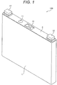
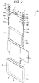
- FIG. 1 is an external perspective view of a rectangular secondary battery and FIG. 2 is an exploded perspective view of the rectangular secondary battery illustrated in FIG. 1 .
- a rectangular secondary battery 100 is a flat wound battery including a flat wound group 3 and includes a battery can 1 and a battery lid 6 that constitute a battery case storing the wound group 3.
- the battery can 1 has sides, which include a pair of wide sides 1b facing each other and having a relatively large area and a pair of narrow sides 1c facing each other and having a relatively small area, and a rectangular bottom 1d, and the battery can has an opening 1a opening upward at the upper portion of the battery can.
- the wound group 3 is stored in the battery can 1, and the opening 1a of the battery can 1 is sealed by the battery lid 6.
- the battery lid 6 has a substantially rectangular flat plate shape and is welded to cover the upper opening 1a of the battery can 1 so that the battery can 1 is sealed.
- the battery lid 6 is provided with a positive electrode external terminal 14 and a negative electrode external terminal 12. Through the positive electrode external terminal 14 and the negative electrode external terminal 12, the wound group 3 is electrically charged and electric power is supplied to an external load.
- a gas release vent 10 is integrally provided in the battery lid 6, and when the pressure in the battery case is increased, the gas release vent 10 opens, releases gas from the inside, and reduces the pressure in the battery case. Therefore, the safety of the rectangular secondary battery 100 is ensured.
- the wound group 3 is stored in the battery can 1 through an insulation protection film 2.
- the wound group 3 Since the wound group 3 is flatly wound, the wound group 3 includes a pair of curved parts having semicircular cross-sectional shapes and facing each other and a flat part continuously formed between the pair of curved parts.
- the wound group 3 is inserted into the battery can 1 from one of the curved parts so that the winding axis direction of the wound group 3 coincides with the width direction of the battery can 1.
- the other curved part is disposed at the upper opening of the battery can 1.
- a positive electrode metal foil-exposed portion 34b of the wound group 3 is electrically connected to the positive electrode external terminal 14 provided on the battery lid 6 through a positive electrode current collecting plate 44. Further, a negative electrode metal foil-exposed portion 32b of the wound group 3 is electrically connected to the negative electrode external terminal 12 provided on the battery lid 6 through a negative electrode current collecting plate 24. Therefore, electric power is supplied from the wound group 3 to an external load through the positive electrode current collecting plate 44 and the negative electrode current collecting plate 24, and electric power generated from the outside is supplied to the wound group 3 through the positive electrode current collecting plate 44 and the negative electrode current collecting plate 24 and the wound group 3 is electrically charged.
- the battery lid 6 is provided with gaskets 5 and insulating plates 7. Further, an electrolyte is filled into the battery can 1 through an injection vent 9. Thereafter, a vent plug 11 is welded to the battery lid 6 by laser welding to seal the injection vent 9, by which the rectangular secondary battery 100 is hermetically sealed.
- materials for forming the positive electrode external terminal 14 and the positive electrode current collecting plate 44 for example, an aluminum alloy is mentioned, and as materials for forming the negative electrode external terminal 12 and the negative electrode current collecting plate 24, for example, a copper alloy is mentioned.
- materials for forming the insulating plate 7 and the gasket 5 for example, resin materials having insulation property such as polybutylene terephthalate, polyphenylenesulfide, and perfluoroalkoxy fluorine resins are mentioned.
- the injection vent 9 used for injecting an electrolyte into the battery case is formed in the battery lid 6, and the injection vent 9 is sealed by the vent plug 11 after the electrolyte is injected into the battery case.
- a non-aqueous electrolyte in which a lithium salt such as lithium hexafluorophosphate (LiPF 6 ) is dissolved in a carbonate ester-based organic solvent such as ethylene carbonate can be employed.
- Each of the positive electrode external terminal 14 and the negative electrode external terminal 12 has a welding joint part to be joined to a bus bar or the like by means of welding.
- the welding joint part has a rectangular parallelepiped block shape protruding upward from the battery lid 6 and has a configuration in which the lower surface faces the surface of the battery lid 6 and the upper surface extends in parallel with the battery lid 6 at a predetermined height position.
- a positive electrode joint 14a and a negative electrode joint 12a each have a cylindrical shape protruding from the lower surface of each of the positive electrode external terminal 14 and the negative electrode external terminal 12 so that each tip end can be inserted into each of a positive electrode side through-hole 46 and a negative electrode side through-hole 26 of the battery lid 6.
- the positive electrode joint 14a and the negative electrode joint 12a each protrude through the battery lid 6 to reach the inside of the battery can 1 from each of a fixed portion 44a of the positive electrode current collecting plate 44 and a fixed portion 24a of the negative electrode current collecting plate 24, and each tip end is caulked, by which the positive electrode external terminal 14, the negative electrode external terminal 12, the positive electrode current collecting plate 44, and the negative electrode current collecting plate 24 each are integrally fixed to the battery lid 6.
- Each gasket 5 is interposed between the positive electrode external terminal 14 and the battery lid 6 and between the negative electrode external terminal 12 and the battery lid 6, and each insulating plate 7 is arranged between the positive electrode current collecting plate 44 and the battery lid 6 and between the negative electrode current collecting plate 24 and the battery lid 6.
- the positive electrode current collecting plate 44 and the negative electrode current collecting plate 24 have the fixed portion 44a and the fixed portion 24a in a rectangular plate shape which are arranged to face the lower surface of the battery lid 6 and a welded portion 44c and a welded portion 24c each which are bent at a lateral edge of each of the fixed portion 44a and the fixed portion 24a, extend toward the bottom 1d along the wide side 1b of the battery can 1, and are connected to each of the positive electrode metal foil-exposed portion 34b and the negative electrode metal foil-exposed portion 32b of the wound group 3 in a state of being overlapped on each of the positive electrode metal foil-exposed portion 34b and the negative electrode metal foil-exposed portion 32b to face each of the positive electrode metal foil-exposed portion 34b and the negative electrode metal foil-exposed portion 32b, respectively.
- a positive electrode side opening 43 and a negative electrode side opening 23 into which the positive electrode joint 14a and the negative electrode joint 12a are respectively inserted are formed in the fixed portion 44a and the fixed portion 24a, respectively
- the insulation protection film 2 is wound around the wound group 3.
- the insulation protection film 2 is wound around the wound group 3 using a direction along the flat surface of the wound group 3 and perpendicular to the winding axis direction of the wound group 3 as a central axis direction.
- the insulation protection film 2 is formed by a sheet made of a synthetic resin such as polypropylene (PP) or a plurality of film members, and when winding is performed using a direction parallel to the flat surface of the wound group 3 and perpendicular to the winding axis direction as a winding center, the insulation protection film 2 has such a size that enables the entire wound group to be completely covered by at least one turn or more of winding of the insulation protection film.
- PP polypropylene
- FIG. 3 is an exploded perspective view illustrating a state where a part of the wound group is developed.
- the wound group 3 is configured by flatly winding a negative electrode 32 and a positive electrode 34 with separators 33 and 35 interposed therebetween.
- the outermost electrode of the wound group 3 is the negative electrode 32 and the separators 33 and 35 are wound around the outside thereof.
- the separators 33 and 35 insulate the positive electrode 34 from the negative electrode 32.
- a portion to which a negative electrode mixture layer 32a of the negative electrode 32 is applied is larger in the width direction than a portion to which a positive electrode mixture layer 34a of the positive electrode 34 is applied and the portion to which the positive electrode mixture layer 34a is applied is overlapped to be necessarily held by the portion to which the negative electrode mixture layer 32a is applied.
- the positive electrode metal foil-exposed portion 34b and the negative electrode metal foil-exposed portion 32b are bundled at a flat portion and then connected by welding or the like.
- the separators 33 and 35 are larger in the width direction than the portion to which the negative electrode mixture layer 32a is applied but are wound at positions where metal foil surfaces are exposed on the ends of the positive electrode metal foil-exposed portion 34b and the negative electrode metal foil-exposed portion 32b. Thus, this does not hamper welding of the bundled exposed portions.
- the positive electrode 34 has the positive electrode mixture layer 34a, which is formed by coating both surfaces of a positive electrode metal foil serving as a positive electrode current collector with a positive electrode mixture containing a positive electrode active material, and is provided with the positive electrode metal foil-exposed portion 34b, which is not coated with the positive electrode mixture, at an end of the positive electrode metal foil in one direction of the width direction.
- the negative electrode 32 has the negative electrode mixture layer 32a, which is formed by coating both surfaces of a negative electrode foil serving as a negative electrode current collector with a negative electrode mixture containing a negative electrode active material, and is provided with the negative electrode metal foil-exposed portion 32b, which is not coated with the negative electrode mixture, at an end of the negative electrode metal foil in the other direction of the width direction.
- the positive electrode metal foil-exposed portion 34b and the negative electrode metal foil-exposed portion 32b are regions where the metal surface of the electrode foil is exposed, and the wound group 3 is wound such that the positive electrode metal foil-exposed portion 34b and the negative electrode metal foil-exposed portion 32b are disposed at the positions in the one direction and the other direction of the winding axis direction, respectively.
- the negative electrode 32 10 parts by weight of polyvinylidene fluoride (hereinafter, referred to as PVDF) as a binder was added to 100 parts by weight of amorphous carbon powder as a negative electrode active material, N-methylpyrrolidone (hereinafter, referred to as NMP) as a dispersing solvent was added thereto, and the obtained mixture was then kneaded to thereby prepare a negative electrode mixture.
- the negative electrode mixture was applied to both surfaces of copper foil (negative electrode metal foil) having a thickness of 10 ⁇ m, except for a negative electrode uncoated portion serving as a welded portion. Thereafter, the foil was subjected to drying, pressing, and cutting processes to obtain the negative electrode 32 having a portion coated with the negative electrode active material without containing a copper foil with a thickness of 70 ⁇ m.
- the negative electrode active material is not limited thereto.
- the negative electrode active material may be natural graphite allowing insertion and desorption of lithium ions, various artificial graphite materials, carbonaceous materials such as coke, a compound of materials such as Si and Sn (for example, SiO or TiSi 2 ), or a composite material thereof.
- the forms of particles include scaly, spherical, fibrous, and massive forms and are not particularly limited.
- the positive electrode 34 10 parts by weight of scaly graphite as a conductive material and 10 parts by weight of PVDF as a binder were added to 100 parts by weight of lithium manganate (chemical formula LiMn 2 O 4 ) as a positive electrode active material, NMP as a dispersing solvent was added thereto and the obtained mixture was then kneaded to thereby prepare a positive electrode mixture.
- the positive electrode mixture was applied to both surfaces of aluminum foil (positive electrode metal foil) having a thickness of 20 ⁇ m, except for a positive electrode uncoated portion serving as a welded portion. Thereafter, the foil was subjected to drying, pressing, and cutting processes to obtain the positive electrode 34 having a portion coated with the positive electrode active material without containing an aluminum foil with a thickness of 90 ⁇ m.
- lithium manganate is used as the positive electrode active material
- another lithium manganate having a spinel crystal structure a lithium manganese complex oxide partially substituted by or doped with a metallic element, lithium cobaltate or lithium titanate having a laminar crystal structure, or a lithium-metal composite oxide obtained by substitution or doping of some of these substances with metallic elements may be used.
- PVDF polytetrafluoroethylene
- PTFE polytetrafluoroethylene
- polyethylene polystyrene
- polybutadiene butyl rubber
- nitrile rubber styrene-butadiene rubber
- polysulfide rubber nitrocellulose, cyanoethylcellulose
- various kinds of latex acrylonitrile, vinyl fluoride, vinylidene fluoride, propylene fluoride, chloroprene fluoride, acrylic resin, or the like, and a mixture thereof can be used as a binder.
- a shaft core configured by winding a resin sheet having higher flexural rigidity than the positive electrode metal foil, the negative electrode metal foil, and the separators 33 and 35 can be used.
- the wound group 3 may have a structure having no shaft core.
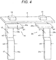
- FIG. 4 is an exploded perspective view of a lid assembly in Example 1
- FIGS. 5(a) to 5(c) are diagrams for describing the configuration of a positive electrode current collecting plate in Example 1.
- FIG. 5(a) is a perspective view schematically illustrating the positive electrode current collecting plate
- FIG. 5(b) is a view as seen in the b arrow direction of FIG. 5(a)
- FIG. 5(c) is a view as seen in the c arrow direction of FIG. 5(a) .
- the lid assembly has, as described in FIG. 4 , the battery lid 6, the positive electrode external terminal 14 and the negative electrode external terminal 12 which are provided on the battery lid 6, the positive electrode current collecting plate 44 which is integrally caulked and fixed to the battery lid 6 by the positive electrode external terminal 14, and the negative electrode current collecting plate 24 which is integrally caulked and fixed to the battery lid 6 by the negative electrode external terminal 12.
- the positive electrode current collecting plate 44 has the fixed portion 44a, the joint 44b, and the welded portion 44c
- the negative electrode current collecting plate 24 has the fixed portion 24a, the joint 24b, and the welded portion 24c.
- the positive electrode side opening 43 and the negative electrode side opening 23 are provided in the fixed portions 44a and 24a respectively but are not illustrated in the drawing.
- the fixed portions 44a and 24a are fixed to face the battery lid 6.
- the welded portions 44c and 24c are welded to the wound group 3.
- the joints 44b and 24b connect the fixed portions 44a and 24a with the welded portions 44c and 24c respectively and face the lateral wall of the battery can 1.
- widths w2 and w5 of the joints 44b and 24b are equal to or less than widths w3 and w6 of the welded portions 44c and 24c and widths w1 and w4 of the fixed portions 44a and 24a.
- the widths w1 and w4 of the fixed portions 44a and 24a are largest, and the widths w2 and w5 of the joints 44b and 24b and the widths w3 and w6 of the welded portions 44c and 24c have the same width.
- the joint 44b has a width portion equal to or less than the widths of the fixed portion 44a and the welded portion 44c and a thickness portion thicker than the fixed portion 44a or the welded portion 44c.
- the negative electrode current collecting plate 24 has a constant thickness t4 in all of the fixed portion 24a, the joint 24b, and the welded portion 24c; meanwhile, in the positive electrode current collecting plate 44 that is the feature configuration of the present invention, a thickness t2 of the joint 44b is thicker than thicknesses t1 and t3 of the fixed portion 44a and the welded portion 44c.
- the positive electrode current collecting plate 44 is produced by casting, forging, or a method using casting and forging in combination.
- the positive electrode current collecting plate 44 is produced, for example, by casting aluminum or an aluminum alloy.
- the negative electrode current collecting plate 24 may be produced, similarly to the positive electrode current collecting plate 44, by casting, forging, or a method using casting and forging in combination or may be produced by bending a plate material having a certain thickness.
- the positive electrode current collecting plate 44 has a portion satisfying a relation of t2 > t1 or t2 > t3.
- the thickness t2 of the joint 44b is thickest, and the thicknesses t1 and t3 of the fixed portion 44a and the welded portion 44c have the same thickness.
- the width w2 of the joint 44b is equal to or less than the width w1 of the fixed portion 44a and the width w3 of the welded portion 44c, and the thickness t2 of the joint 44b is thicker than the thickness t1 of the fixed portion 44a and the thickness t3 of the welded portion 44c.
- a cross-sectional area S2 of the joint 44b is largest, a cross-sectional area S1 of the fixed portion 44a is secondly largest, and a cross-sectional area S3 of the welded portion 44c is smallest.
- the fixed portion 44a of the positive electrode current collecting plate 44 is connected to the positive electrode external terminal 14, can transfer heat directly to the positive electrode external terminal 14 to release heat, and has satisfactory heat dissipation performance. Further, the welded portion 44c is connected to the wound group 3 having a large thermal capacity and can transfer heat directly to the wound group 3 to release heat, and the temperature thereof is less likely to increase. On the other hand, the joint 44b does not have a portion which can transfer heat directly and the temperature thereof is most prone to reach a high temperature among the portions of the positive electrode current collecting plate 44. Therefore, it is most effective to suppress heat generation of the joint 44b.
- the thickness t2 of the joint 44b is set to be thicker than the thickness t1 of the fixed portion 44a and the thickness t3 of the welded portion 44c. Therefore, as compared to the fixed portion 44a and the welded portion 44c, a current resistance value of the joint 44b can be lowered and thus the heat generation of the joint 44b can be suppressed.
- the effect of suppressing heat generation is largest, but even when only a portion of the entire joint 44b is thick, the effect of suppressing heat generation is obtained at the portion.
- a maximum thickness t1max of the fixed portion 44a and a maximum thickness t2max of the joint 44b have a relation of t2max > t1max
- a minimum thickness t1min of the fixed portion 44a and a minimum thickness t2min of the joint 44b have a relation of t2min ⁇ t1min.
- the heat generation suppression effect is smaller as compared to a case where the entire joint 44b has a thickness relation of t2 > t1 with respect to the fixed portion 44a, but the weight can be decreased and the material cost can be decreased.
- a maximum thickness t3max of the welded portion 44c and a maximum thickness t2max of the joint 44b have a relation of t2max > t3max and a minimum thickness t3min of the welded portion 44c and a minimum thickness t2min of the joint 44b have a relation of t2min ⁇ t3min.
- the heat generation suppression effect is smaller as compared to a case where the entire joint 44b has a thickness relation of t2 > t3 with respect to the welded portion 44c, but the weight can be decreased and the material cost can be decreased.
- the joint 44b of the positive electrode current collecting plate 44 is thicker than the fixed portion 44a and the welded portion 44c (t2 > t1 or t2 > t3) has been described, but instead of the positive electrode current collecting plate 44, the joint 24b of the negative electrode current collecting plate 24 may be thicker than the fixed portion 24a and the welded portion 24c or the joints 44b and 24b may be configured to be thick in both the positive electrode current collecting plate 44 and the negative electrode current collecting plate 24.
- the cross-sectional shape of the joint 44b is a rectangular shape
- the cross-sectional shape thereof may be a circular shape, an elliptical shape, or a polygonal shape.
- FIG. 6 is a diagram illustrating temperature distribution in the current collecting plate of Example 1 and is an isothermal diagram with a scale of 1°C.
- FIG. 6 and Table 1 present simulation results when 500 A of current flows to the positive electrode current collecting plate 44.
- the fixed portion 44a and the welded portion 44c have a setting in which heat easily releases outside.
- [Table 1] t2 (mm) W2 (mm) S2/S1 maxT mean T max-mean Conventional product 2 15 0.75 113.1 103.1 10 Example 1 4 15 1.5 88.2 84.0 4.2 maxT: a maximum temperature (°C) of the current collecting plate meanT: an average temperature (°C) of the entire current collecting plate max - mean: a difference between the maximum temperature and the average temperature S1 40 (mm 2 )
- the thicknesses of the fixed portion, the joint, and the welded portion are constant to one another; meanwhile, in the current collecting plate of Example 1, the thickness of the joint 44b is twice the thickness of each of the fixed portion 44a and the welded portion 44c.
- the maximum heat generation place when a current flows was the joint, the maximum temperature thereof was 113.1°C, and a difference between the maximum temperature and the average temperature was 10°C.
- the maximum heat generation place when a current flows was the joint 44b, the maximum temperature thereof was 88.2°C, and a difference between the maximum temperature and the average temperature was 4.2°C.
- Example 1 it was found out that when the thickness of the joint 44b is set to be thicker than the fixed portion 44a, the cross-sectional area is increased and the electric resistance is decreased so that the difference between the heat generation maximum temperature and the average temperature when a current flows can be further suppressed as compared to the case of the conventional product.
- Example 2 will be described using FIGS. 7(a) to 7(c) .
- FIGS. 7(a) to 7(c) are diagrams for describing the configuration of a current collecting plate in Example 2. Incidentally, constituent elements equivalent to those in Example 1 described above are assigned the same reference numerals as in Example 1 and detailed description thereof is omitted.
- Characteristic features in this Example are as follows. As compared to the configuration of Example 1, the thickness of a welded portion of a positive electrode current collecting plate 144 is also set to be increased, and heat generation of the welded portion can also be suppressed in addition to the effect of Example 1.
- the positive electrode current collecting plate 144 is produced, similarly to the positive electrode current collecting plate 44 of Example 1, by casting, forging, or a method using casting and forging in combination.
- the positive electrode current collecting plate 144 has a portion satisfying a relation of t2 > t1 and t3 > t1. That is, the welded portion 144c has a thickness portion thicker than the fixed portion 44a.
- the thickness t2 of the joint 44b and the thickness t3 of the welded portion 144c are set to be the same thickness and to be thicker than the thickness t1 of the fixed portion 44a. Therefore, resistance values of the joint 44b and the welded portion 144c are lowered, and thus heat generation of the joint 44b and the welded portion 144c can be suppressed.
- the thickness t2 of the joint 44b and the thickness t3 of the welded portion 144c are set to be thicker than the thickness t1 of the fixed portion 44a, as compared to the fixed portion 44a, current resistance values of the joint 44b and the welded portion 144c can be lowered and heat generation of the joint 44b can be suppressed.
- the welded portion 144c is thick, when the welded portion 144c is welded to the positive electrode metal foil-exposed portion 34b of the wound group 3, an amount of welding penetration can be increased in laser welding, and in ultrasonic welding, force is easily applied when the welded portion is held by an anvil and a horn and the number of sheets of the positive electrode metal foil-exposed portion 34b overlapped can be increased.
- Example 3 will be described using FIGS. 8(a) to 8(c) and FIGS. 9(a) to 9(c) .
- FIGS. 8(a) to 8(c) are diagrams for describing the configuration of a current collecting plate in Example 3 and FIGS. 9(a) to 9(c) are diagrams for describing an arrangement state of the current collecting plate and a wound group in a battery case of a rectangular secondary battery.
- FIG. 9(a) is a diagram illustrating a part of the rectangular secondary battery seen from the front face
- FIG. 9(b) is a cross-sectional view taken along b-b line of FIG. 9(a)
- FIG. 9(c) is a cross-sectional view taken along c-c line of FIG. 9(a) .
- constituent elements equivalent to those in each Example described above are assigned the same reference numerals as in each Example and detailed description thereof is omitted.
- Characteristic features in this Example are as follows.
- the thickness of a joint 244b of a positive electrode current collecting plate 244 is set to be thicker than the fixed portion 44a and the welded portion 44c and the width of the joint 244b is set to be narrower than the fixed portion 44a and the welded portion 44c.
- the positive electrode current collecting plate 244 is produced, similarly to the positive electrode current collecting plate 44 of Example 1, by casting, forging, or a method using casting and forging in combination. Particularly, as illustrated in FIG. 8(c) , in the positive electrode current collecting plate 244, the width W2 of the joint 244b is narrower than the width W3 of the welded portion 44c. Further, as illustrated in FIG. 8(b) , the thickness t2 of the joint 244b is thicker than the thickness t1 of the fixed portion 44a and the thickness t3 of the welded portion 44c. As illustrated in FIG. 8(c) , the width of the joint 244b is narrowed to be close to one side of the fixed portion 44a in the longitudinal direction. In this Example, among the fixed portion 44a, the joint 244b, and the welded portion 44c, the thickness t2 of the joint 244b is thickest and the width W2 of the joint 244b is smallest.
- a minimum cross-sectional area portion of the joint 244b in a direction perpendicular to a current path is larger than at least one of each minimum cross-sectional area portion of the fixed portion 44a and the welded portion 44c in the direction perpendicular to the current path.
- the positive electrode current collecting plate 244 has a portion satisfying a relation of S2 > S1 and W2 ⁇ W1 or S2 > S3 and W2 ⁇ W3.
- the width of the joint 244b is narrowed, when the positive electrode current collecting plate 244 is assembled as the rectangular secondary battery 100, as illustrated in FIG. 9(b) , a space corresponding to the narrowed width is formed inside the battery can 1, and a position of the positive electrode current collecting plate which interferes with the positive electrode metal foil-exposed portion 34b of the wound group 3 can be disposed at a position close to the outside of the wound group 3 in the winding axis direction. Therefore, the width of the positive electrode metal foil-exposed portion 34b in the wound group 3 can be further shortened, and the widths of the positive electrode mixture layer 34a and the negative electrode mixture layer 32a can be widened.
- the thickness t2 of the joint 244b is thickest. Therefore, in addition to the same efface as in Example 1 that heat generation can be suppressed by lowering the electric resistance of the joint 244b, the effect that the volume of the rectangular secondary battery 100 can be increased by using a space inside the battery can generated by narrowing the width w2 of the joint 244b can be exhibited.
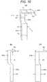
- Example 4 will be described using FIGS. 10(a) to 10(c) .
- FIGS. 10(a) to 10(c) are diagrams for describing the configuration of a current collecting plate in Example 4. Incidentally, constituent elements equivalent to those in each Example described above are assigned the same reference numerals as in each Example and detailed description thereof is omitted.
- a characteristic feature in this Example is as follows. As compared to the configuration of Example 3, the thickness of a welded portion 344c of a positive electrode current collecting plate 344 is also set to be thick.
- the positive electrode current collecting plate 344 is produced, similarly to the positive electrode current collecting plate 244 of Example 3, by casting, forging, or a method using casting and forging in combination.
- the positive electrode current collecting plate 344 has a portion satisfying a relation of t2 > t1 and t3 > t1.
- a minimum cross-sectional area portion of the welded portion 344c in the direction perpendicular to the current path is larger than a minimum cross-sectional area portion of the fixed portion 44a in the direction perpendicular to the current path.
- the positive electrode current collecting plate 344 has a relation of S2 > S1, W2 ⁇ W1, S3 > S1, and W3 ⁇ W1.
- Example 3 since the thickness t2 of the joint 344b and the thickness t3 of the welded portion 344c are set to be thicker than the thickness t1 of the fixed portion 44a, resistance values of the joint 344b and the welded portion 344c are lowered, and thus heat generation of the joint 344b and the welded portion 344c is suppressed. Therefore, in addition to the effect of Example 3 that the volume of the rectangular secondary battery 100 can be increased, current resistance values of the joint 344b and the welded portion 344c can be further lowered as compared to the fixed portion 44a and the effect that heat generation of the joint 344b can be suppressed is obtained.
- the welded portion 344c is thick, when the welded portion 344c is welded to the positive electrode metal foil-exposed portion 34b of the wound group 3, an amount of welding penetration can be increased in laser welding, and in ultrasonic welding, force is easily applied when the welded portion is held by an anvil and a horn and the number of sheets of the positive electrode metal foil-exposed portion 34b overlapped can be increased.
- FIGS. 11(a) to 11(c) are diagrams for describing the configuration of a current collecting plate in Example 5
- FIG. 12(a) is a cross-sectional view taken along d-d line of FIG. 11(c)
- FIG. 12(b) is a diagram corresponding to Example 1
- FIG. 13 is a diagram illustrating temperature distribution in the current collecting plate of Example 5 and an isothermal diagram with a scale of 1°C.
- constituent elements equivalent to those in each Example described above are assigned the same reference numerals as in each Example and detailed description thereof is omitted.
- a characteristic feature in this Example is as follows. As illustrated in FIG. 11(b) , the thickness of a joint portion of the joint 44b with the fixed portion 44a is configured to be thicker than the thickness of the joint portion close to the welded portion 44c.
- a positive electrode current collecting plate 444 is produced, similarly to the positive electrode current collecting plate 44 of Example 1, by casting, forging, or a method using casting and forging in combination.
- the positive electrode current collecting plate 444 is provided with an R portion 444d, in which the thickness t2 of the joint 44b is gradually increased, at a joint portion of the joint 44b with the fixed portion 44a, as compared to the configuration of Example 1.
- the R portion 444d is formed such that the thickness t2 is gradually increased as being close to the fixed portion 44a and the R portion 444d is smoothly continued to the surface of the fixed portion 44a.
- Example 1 a joint portion of the joint 44b with the fixed portion 44a is formed at an approximately right angle. Further, since the cross-sectional area of the fixed portion 44a and the cross-sectional area of the joint 44b are different from each other, current densities flowing in each of fixed portion 44a and the joint 44b are also different from each other. Therefore, for example, when a large current flows from the fixed portion 44a toward the joint 44b, there is a concern that current concentration occurs in the corner portion and thus heat generation occurs at the corner portion. On the other hand, in this Example, as illustrated in FIG.
- FIG. 13 and Table 2 present simulation results of Joule heat generation when 500 A of current flows to the positive electrode current collecting plate 444.
- r1 (mm) maxT mean T max-mean Example 1 0 88.2 84.0 4.2
- Example 5 the curvature radius r1 of the R portion 444d was set to have a dimension of 6 mm. That is, the conventional product is not provided with the R portion; meanwhile, the positive electrode current collecting plate 444 of Example 5 has the R portion 444d, in which the thickness t2 of the joint 44b is gradually increased and which is smoothly continued to the surface of the fixed portion 44a, at the joint portion of the joint 44b with the fixed portion 44a.
- Example 1 the maximum heat generation place when a current flows was the joint 44b, the maximum temperature thereof was 88. 2°C, and a difference between the maximum temperature and the average temperature was 4.2°C. Meanwhile, according to the simulation results of Example 5, the maximum heat generation place when a current flows was the joint 44b, the maximum temperature thereof was 86.0°C, and a difference between the maximum temperature and the average temperature was 3.8°C.
- Example 5 it was found out that when current concentration at the joint portion is alleviated by providing the R portion 444d at the joint portion of the joint 44b with the fixed portion 44a, the difference between the heat generation maximum temperature and the average temperature when current flows can be further suppressed as compared to Example 1.
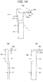
- Example 6 will be described using FIGS. 14(a) to 14(c) and FIG. 15 .
- FIGS. 14(a) to 14(c) are diagrams for describing the configuration of a current collecting plate in Example 6, and FIG. 15 is a diagram illustrating temperature distribution in the current collecting plate of Example 6 and an isothermal diagram with a scale of 1°C.
- constituent elements equivalent to those in each Example described above are assigned the same reference numerals as in each Example and detailed description thereof is omitted.
- a characteristic feature in this Example is as follows. As illustrated in FIG. 14(c) , the width of the joint portion of the joint 44b with the fixed portion 44a is configured to be larger than the width of the joint portion close to the welded portion 44c.
- a positive electrode current collecting plate 544 is produced, similarly to the positive electrode current collecting plate 44 of Example 1, by casting, forging, or a method using casting and forging in combination.
- the positive electrode current collecting plate 544 is provided with an R portion 544e, in which the width W2 of the joint 44b is gradually increased, at the joint portion of the joint 44b with the fixed portion 44a, as compared to the configuration of Example 1.
- the R portion 544e is formed such that width W2 is gradually increased as being close to the fixed portion 44a and the R portion 544e is smoothly continued to the surface of the fixed portion 44a.
- FIG. 15 and Table 3 present simulation results of Joule heat generation when 500 A of current flows to the positive electrode current collecting plate 544.
- r2 (mm) maxT mean T max-mean Example 1 0 88.2 84.0 4.2
- Example 6 6 86.1 82.1 4.0 r2: a curvature radius of the R portion
- Example 6 the curvature radius r2 of the R portion 544e was set to have a dimension of 6 mm. That is, the conventional product is not provided with the R portion; meanwhile, the positive electrode current collecting plate 544 of Example 6 has the R portion 544e, in which the width W2 of the joint 44b is gradually increased and which is smoothly continued to the surface of the fixed portion 44a, at the joint portion of the joint 44b with the fixed portion 44a and the positive electrode current collecting plate 544.
- Example 1 the maximum heat generation place when a current flows was the joint 44b, the maximum temperature thereof was 88.2°C, and a difference between the maximum temperature and the average temperature was 4.2°C. Meanwhile, according to the simulation results of Example 6, the maximum heat generation place when a current flows was the joint 44b, the maximum temperature thereof was 86.1°C, and a difference between the maximum temperature and the average temperature was 4.0°C.
- Example 6 it was found out that when current concentration at the joint portion is alleviated by providing the R portion 544e at the joint portion of the joint 44b with the fixed portion 44a, the difference between the heat generation maximum temperature and the average temperature when current flows can be further suppressed as compared to Example 1.
- Example 7 will be described using FIGS. 16(a) to 16(c) .
- FIGS. 16(a) to 16(c) are diagrams for describing the configuration of a current collecting plate in Example 7. Incidentally, constituent elements equivalent to those in each Example described above are assigned the same reference numerals as in each Example and detailed description thereof is omitted.
- Characteristic features in this Example are as follows. As illustrated in FIG. 16(b) , the thickness of the joint portion of the joint 44b with the fixed portion 44a is configured to be thicker than the thickness of the joint portion close to the welded portion 44c, and as illustrated in FIG. 16(c) , the width of the joint portion of the joint 44b with the fixed portion 44a is configured to be larger than the width of the joint portion close to the welded portion 44c.
- the positive electrode current collecting plate 644 is produced, similarly to the positive electrode current collecting plate 44 of Example 1, by casting, forging, or a method using casting and forging in combination.
- an R portion 644d in which the thickness t2 of the joint 44b is gradually increased and an R portion 644e in which the width W2 of the joint 44b is gradually increased are provided at the joint portion of the joint 44b with the fixed portion 44a, as compared to the configuration of Example 1.
- the R portion 644d is formed such that the thickness t2 is gradually increased as being close to the fixed portion 44a and the R portion 644d is smoothly continued to the surface of the fixed portion 44a.
- the R portion 644e is formed such that the width W2 is gradually increased as being close to the fixed portion 44a and the R portion 644e is smoothly continued to the surface of the fixed portion 44a.
- Example 8 will be described using FIGS. 17(a) to 17(c) .
- FIGS. 17(a) to 17(c) are diagrams for describing the configuration of a current collecting plate in Example 8. Incidentally, constituent elements equivalent to those in each Example described above are assigned the same reference numerals as in each Example and detailed description thereof is omitted.
- Characteristic features in this Example are as follows. As compared to the configuration of Example 1, the thickness of a fixed portion of a positive electrode current collecting plate 744 is also increased, and in addition to the effect of Example 1, heat generation of the fixed portion can also be suppressed.
- the positive electrode current collecting plate 744 is produced, similarly to the positive electrode current collecting plate 44 of Example 1, by casting, forging, or a method using casting and forging in combination.
- the positive electrode current collecting plate 744 has a portion satisfying a relation of t2 > t3 and t1 > t3. Therefore, resistance values of the joint 44b and the fixed portion 744a are lowered, and thus heat generation of the fixed portion 744a and the joint 44b can be suppressed.
- the thickness t1 of the fixed portion 744a and the thickness t2 of the joint 44b are set to be thicker than the thickness t3 of the welded portion 44c, as compared to the welded portion 44c, current resistance values of the fixed portion 744a and the joint 44b can be lowered and heat generation of the joint 44b can be suppressed. Further, since the fixed portion 744a is thick, the fixed portion 744a has high rigidity, and when the fixed portion 744a is fixed to the battery lid 6 by caulking-fixation, the fixed portion 744a can be more strongly fixed.
- the configuration of the present invention may be applied to the negative electrode or can be applied to both the positive electrode and the negative electrode.
Description
- The present invention relates to a secondary battery in which a wound group is stored inside a battery can and electric power is extracted from the wound group through a current collecting plate, and particularly to a rectangular secondary battery in which the structure of the current collecting plate is improved.
- In recent years, cylindrical and rectangular secondary batteries that are batteries having high energy densities have been developed as power sources of electric vehicles and so on. Among these, as a technique that is mostly employed in rectangular secondary batteries, a technique disclosed in
PTL 1 is proposed. In thisPTL 1, it is described that "There is provided a secondary battery capable of preventing occurrence of positional deviation in each electrode group when a current collecting plate jointed with a plurality of electrode groups is bent to dispose each electrode group at a predetermined arrangement position so that miniaturization of the entire battery can be achieved (see Abstract)." This current collecting plate is mostly produced by performing press processing on a metallic plate, and the thickness thereof is constant. -
EP 2 827 406 A1 - In
EP 2 506 358 A1 - In
WO 2013/168260 A1 , a secondary battery is provided with a battery container in which a wound electrode group is provided. A positive electrode collector plate comprises a positive electrode first collector plate and a positive electrode second collector plate which are bifurcated from a fixation part. - In
JP 2014 082 072 A - PTL 1: Japanese Unexamined Patent Application Publication No.
2013-122842 - In the rectangular secondary batteries, higher current has been demanded, and heat generation in the current collecting plate inside the cell has become a problem. However, the method for producing the current collecting plate using metallic plate is mainly used and the thickness of the entire current collecting plate is constant. For these reasons, there is limitation on the suppression of heat generation of the current collecting plate.
- The present invention has been made in view of the above-described circumstances and an object thereof is to provide a rectangular secondary battery in which heat generation of a current collecting plate is suppressed.
- The problem is solved by providing a rectangular secondary battery with the features of
claim 1. - According to the present invention, heat generation of the current collecting plate can be suppressed. Incidentally, problems, configurations, and effects other than those described above will be apparent from the following description of embodiments.
-
-
FIG. 1 is an external perspective view of a rectangular secondary battery. -
FIG. 2 is an exploded perspective view of the rectangular secondary battery illustrated inFIG. 1 . -
FIG. 3 is an exploded perspective view of a wound group. -
FIG. 4 is an exploded perspective view of a lid assembly in Example 1. -
FIGS. 5(a) to 5(c) are diagrams for describing the configuration of a positive electrode current collecting plate in Example 1. -
FIG. 6 is a diagram illustrating temperature distribution in a current collecting plate of Example 1. -
FIGS. 7(a) to 7(c) are diagrams for describing the configuration of a current collecting plate in Example 2. -
FIGS. 8(a) to 8(c) are diagrams for describing the configuration of a current collecting plate in Example 3. -
FIGS. 9(a) to 9(c) are diagrams for describing an arrangement state of the current collecting plate of Example 3 and a wound group in a battery case. -
FIGS. 10 (a) to 10 (c) are diagrams for describing the configuration of a current collecting plate in Example 4. -
FIGS. 11(a) to 11(c) are diagrams for describing the configuration of a current collecting plate in Example 5. -
FIGS. 12(a) and 12(b) are diagrams for describing the flow of current in each current collecting plate of Example 1 (FIG. 12(b) ) and Example 5 (FIG. 12(a) ). -
FIG. 13 is a diagram illustrating temperature distribution in the current collecting plate of Example 5. -
FIGS. 14(a) to 14(c) are diagrams for describing the configuration of a current collecting plate in Example 6. -
FIG. 15 is a diagram illustrating temperature distribution in the current collecting plate of Example 6. -
FIGS. 16(a) to 16(c) are diagrams for describing the configuration of a current collecting plate in Example 7. -
FIGS. 17(a) to 17(c) are diagrams for describing the configuration of a current collecting plate in Example 8. - Hereinafter, Examples to which the present invention is applied will be described using drawings. Incidentally, in the following each Example, a case where a rectangular secondary battery is a lithium ion secondary battery will be exemplified; however, the rectangular secondary battery is not limited to the lithium ion secondary battery and can also be applied to other batteries.
-
FIG. 1 is an external perspective view of a rectangular secondary battery andFIG. 2 is an exploded perspective view of the rectangular secondary battery illustrated inFIG. 1 . - A rectangular
secondary battery 100 is a flat wound battery including aflat wound group 3 and includes a battery can 1 and abattery lid 6 that constitute a battery case storing thewound group 3. The battery can 1 has sides, which include a pair ofwide sides 1b facing each other and having a relatively large area and a pair ofnarrow sides 1c facing each other and having a relatively small area, and arectangular bottom 1d, and the battery can has an opening 1a opening upward at the upper portion of the battery can. - The
wound group 3 is stored in the battery can 1, and the opening 1a of the battery can 1 is sealed by thebattery lid 6. Thebattery lid 6 has a substantially rectangular flat plate shape and is welded to cover theupper opening 1a of the battery can 1 so that the battery can 1 is sealed. Thebattery lid 6 is provided with a positive electrodeexternal terminal 14 and a negative electrodeexternal terminal 12. Through the positive electrodeexternal terminal 14 and the negative electrodeexternal terminal 12, thewound group 3 is electrically charged and electric power is supplied to an external load. Agas release vent 10 is integrally provided in thebattery lid 6, and when the pressure in the battery case is increased, thegas release vent 10 opens, releases gas from the inside, and reduces the pressure in the battery case. Therefore, the safety of the rectangularsecondary battery 100 is ensured. - The
wound group 3 is stored in the battery can 1 through aninsulation protection film 2. - Since the
wound group 3 is flatly wound, thewound group 3 includes a pair of curved parts having semicircular cross-sectional shapes and facing each other and a flat part continuously formed between the pair of curved parts. Thewound group 3 is inserted into the battery can 1 from one of the curved parts so that the winding axis direction of thewound group 3 coincides with the width direction of the battery can 1. In this state, the other curved part is disposed at the upper opening of the battery can 1. - A positive electrode metal foil-exposed
portion 34b of thewound group 3 is electrically connected to the positive electrodeexternal terminal 14 provided on thebattery lid 6 through a positive electrodecurrent collecting plate 44. Further, a negative electrode metal foil-exposedportion 32b of thewound group 3 is electrically connected to the negative electrodeexternal terminal 12 provided on thebattery lid 6 through a negative electrodecurrent collecting plate 24. Therefore, electric power is supplied from thewound group 3 to an external load through the positive electrodecurrent collecting plate 44 and the negative electrodecurrent collecting plate 24, and electric power generated from the outside is supplied to thewound group 3 through the positive electrodecurrent collecting plate 44 and the negative electrodecurrent collecting plate 24 and thewound group 3 is electrically charged. - For the purpose of the electrical insulation of the positive electrode
current collecting plate 44, the negative electrode current collectingplate 24, the positive electrodeexternal terminal 14, and the negative electrodeexternal terminal 12 from thebattery lid 6, thebattery lid 6 is provided withgaskets 5 andinsulating plates 7. Further, an electrolyte is filled into the battery can 1 through an injection vent 9. Thereafter, avent plug 11 is welded to thebattery lid 6 by laser welding to seal the injection vent 9, by which the rectangularsecondary battery 100 is hermetically sealed. - Herein, as materials for forming the positive electrode
external terminal 14 and the positive electrodecurrent collecting plate 44, for example, an aluminum alloy is mentioned, and as materials for forming the negative electrodeexternal terminal 12 and the negative electrodecurrent collecting plate 24, for example, a copper alloy is mentioned. In addition, as materials for forming the insulatingplate 7 and thegasket 5, for example, resin materials having insulation property such as polybutylene terephthalate, polyphenylenesulfide, and perfluoroalkoxy fluorine resins are mentioned. - Further, the injection vent 9 used for injecting an electrolyte into the battery case is formed in the
battery lid 6, and the injection vent 9 is sealed by thevent plug 11 after the electrolyte is injected into the battery case. Herein, as the electrolyte to be injected into the battery case, for example, a non-aqueous electrolyte in which a lithium salt such as lithium hexafluorophosphate (LiPF6) is dissolved in a carbonate ester-based organic solvent such as ethylene carbonate can be employed. - Each of the positive electrode
external terminal 14 and the negative electrodeexternal terminal 12 has a welding joint part to be joined to a bus bar or the like by means of welding. The welding joint part has a rectangular parallelepiped block shape protruding upward from thebattery lid 6 and has a configuration in which the lower surface faces the surface of thebattery lid 6 and the upper surface extends in parallel with thebattery lid 6 at a predetermined height position. - A positive electrode joint 14a and a negative electrode joint 12a each have a cylindrical shape protruding from the lower surface of each of the positive electrode
external terminal 14 and the negative electrodeexternal terminal 12 so that each tip end can be inserted into each of a positive electrode side through-hole 46 and a negative electrode side through-hole 26 of thebattery lid 6. The positive electrode joint 14a and the negative electrode joint 12a each protrude through thebattery lid 6 to reach the inside of the battery can 1 from each of a fixedportion 44a of the positive electrodecurrent collecting plate 44 and a fixedportion 24a of the negative electrodecurrent collecting plate 24, and each tip end is caulked, by which the positive electrodeexternal terminal 14, the negative electrodeexternal terminal 12, the positive electrodecurrent collecting plate 44, and the negative electrodecurrent collecting plate 24 each are integrally fixed to thebattery lid 6. Eachgasket 5 is interposed between the positive electrodeexternal terminal 14 and thebattery lid 6 and between the negative electrodeexternal terminal 12 and thebattery lid 6, and each insulatingplate 7 is arranged between the positive electrodecurrent collecting plate 44 and thebattery lid 6 and between the negative electrodecurrent collecting plate 24 and thebattery lid 6. - The positive electrode
current collecting plate 44 and the negative electrodecurrent collecting plate 24 have the fixedportion 44a and the fixedportion 24a in a rectangular plate shape which are arranged to face the lower surface of thebattery lid 6 and a weldedportion 44c and a weldedportion 24c each which are bent at a lateral edge of each of the fixedportion 44a and the fixedportion 24a, extend toward the bottom 1d along thewide side 1b of the battery can 1, and are connected to each of the positive electrode metal foil-exposedportion 34b and the negative electrode metal foil-exposedportion 32b of thewound group 3 in a state of being overlapped on each of the positive electrode metal foil-exposedportion 34b and the negative electrode metal foil-exposedportion 32b to face each of the positive electrode metal foil-exposedportion 34b and the negative electrode metal foil-exposedportion 32b, respectively. A positiveelectrode side opening 43 and a negativeelectrode side opening 23 into which the positive electrode joint 14a and the negative electrode joint 12a are respectively inserted are formed in the fixedportion 44a and the fixedportion 24a, respectively. - The
insulation protection film 2 is wound around thewound group 3. Theinsulation protection film 2 is wound around thewound group 3 using a direction along the flat surface of thewound group 3 and perpendicular to the winding axis direction of thewound group 3 as a central axis direction. Theinsulation protection film 2 is formed by a sheet made of a synthetic resin such as polypropylene (PP) or a plurality of film members, and when winding is performed using a direction parallel to the flat surface of thewound group 3 and perpendicular to the winding axis direction as a winding center, theinsulation protection film 2 has such a size that enables the entire wound group to be completely covered by at least one turn or more of winding of the insulation protection film. -
FIG. 3 is an exploded perspective view illustrating a state where a part of the wound group is developed. - The
wound group 3 is configured by flatly winding anegative electrode 32 and apositive electrode 34 withseparators wound group 3 is thenegative electrode 32 and theseparators separators positive electrode 34 from thenegative electrode 32. - A portion to which a negative
electrode mixture layer 32a of thenegative electrode 32 is applied is larger in the width direction than a portion to which a positiveelectrode mixture layer 34a of thepositive electrode 34 is applied and the portion to which the positiveelectrode mixture layer 34a is applied is overlapped to be necessarily held by the portion to which the negativeelectrode mixture layer 32a is applied. The positive electrode metal foil-exposedportion 34b and the negative electrode metal foil-exposedportion 32b are bundled at a flat portion and then connected by welding or the like. Incidentally, theseparators electrode mixture layer 32a is applied but are wound at positions where metal foil surfaces are exposed on the ends of the positive electrode metal foil-exposedportion 34b and the negative electrode metal foil-exposedportion 32b. Thus, this does not hamper welding of the bundled exposed portions. - The
positive electrode 34 has the positiveelectrode mixture layer 34a, which is formed by coating both surfaces of a positive electrode metal foil serving as a positive electrode current collector with a positive electrode mixture containing a positive electrode active material, and is provided with the positive electrode metal foil-exposedportion 34b, which is not coated with the positive electrode mixture, at an end of the positive electrode metal foil in one direction of the width direction. Thenegative electrode 32 has the negativeelectrode mixture layer 32a, which is formed by coating both surfaces of a negative electrode foil serving as a negative electrode current collector with a negative electrode mixture containing a negative electrode active material, and is provided with the negative electrode metal foil-exposedportion 32b, which is not coated with the negative electrode mixture, at an end of the negative electrode metal foil in the other direction of the width direction. The positive electrode metal foil-exposedportion 34b and the negative electrode metal foil-exposedportion 32b are regions where the metal surface of the electrode foil is exposed, and thewound group 3 is wound such that the positive electrode metal foil-exposedportion 34b and the negative electrode metal foil-exposedportion 32b are disposed at the positions in the one direction and the other direction of the winding axis direction, respectively. - Regarding the
negative electrode negative electrode 32 having a portion coated with the negative electrode active material without containing a copper foil with a thickness of 70 µm. - Incidentally, in this embodiment, a case where amorphous carbon is used as the negative electrode active material has been exemplified, but the negative electrode active material is not limited thereto. The negative electrode active material may be natural graphite allowing insertion and desorption of lithium ions, various artificial graphite materials, carbonaceous materials such as coke, a compound of materials such as Si and Sn (for example, SiO or TiSi2), or a composite material thereof. The forms of particles include scaly, spherical, fibrous, and massive forms and are not particularly limited.
- Regarding the
positive electrode positive electrode 34 having a portion coated with the positive electrode active material without containing an aluminum foil with a thickness of 90 µm. - Further, in this Example, a case where lithium manganate is used as the positive electrode active material has been exemplified, but another lithium manganate having a spinel crystal structure, a lithium manganese complex oxide partially substituted by or doped with a metallic element, lithium cobaltate or lithium titanate having a laminar crystal structure, or a lithium-metal composite oxide obtained by substitution or doping of some of these substances with metallic elements may be used.
- Further, in this Example, a case where PVDF is used as a binder of a coated portion in the positive electrode and the negative electrode has been exemplified, but any polymer of, for example, polytetrafluoroethylene (PTFE), polyethylene, polystyrene, polybutadiene, butyl rubber, nitrile rubber, styrene-butadiene rubber, polysulfide rubber, nitrocellulose, cyanoethylcellulose, various kinds of latex, acrylonitrile, vinyl fluoride, vinylidene fluoride, propylene fluoride, chloroprene fluoride, acrylic resin, or the like, and a mixture thereof can be used as a binder. Furthermore, as a shaft core, a shaft core configured by winding a resin sheet having higher flexural rigidity than the positive electrode metal foil, the negative electrode metal foil, and the
separators wound group 3 may have a structure having no shaft core. -
FIG. 4 is an exploded perspective view of a lid assembly in Example 1, andFIGS. 5(a) to 5(c) are diagrams for describing the configuration of a positive electrode current collecting plate in Example 1.FIG. 5(a) is a perspective view schematically illustrating the positive electrode current collecting plate,FIG. 5(b) is a view as seen in the b arrow direction ofFIG. 5(a), and FIG. 5(c) is a view as seen in the c arrow direction ofFIG. 5(a) . - The lid assembly has, as described in
FIG. 4 , thebattery lid 6, the positive electrodeexternal terminal 14 and the negative electrodeexternal terminal 12 which are provided on thebattery lid 6, the positive electrodecurrent collecting plate 44 which is integrally caulked and fixed to thebattery lid 6 by the positive electrodeexternal terminal 14, and the negative electrodecurrent collecting plate 24 which is integrally caulked and fixed to thebattery lid 6 by the negative electrodeexternal terminal 12. The positive electrodecurrent collecting plate 44 has the fixedportion 44a, the joint 44b, and the weldedportion 44c, and the negative electrodecurrent collecting plate 24 has the fixedportion 24a, the joint 24b, and the weldedportion 24c. Incidentally, actually, the positiveelectrode side opening 43 and the negativeelectrode side opening 23 are provided in the fixedportions - The fixed
portions battery lid 6. The weldedportions wound group 3. Thejoints portions portions - Regarding the positive electrode
current collecting plate 44 and the negative electrodecurrent collecting plate 24, widths w2 and w5 of thejoints portions portions portions joints portions current collecting plate 44, the joint 44b has a width portion equal to or less than the widths of the fixedportion 44a and the weldedportion 44c and a thickness portion thicker than the fixedportion 44a or the weldedportion 44c. - The negative electrode
current collecting plate 24 has a constant thickness t4 in all of the fixedportion 24a, the joint 24b, and the weldedportion 24c; meanwhile, in the positive electrodecurrent collecting plate 44 that is the feature configuration of the present invention, a thickness t2 of the joint 44b is thicker than thicknesses t1 and t3 of the fixedportion 44a and the weldedportion 44c. - The positive electrode
current collecting plate 44 is produced by casting, forging, or a method using casting and forging in combination. The positive electrodecurrent collecting plate 44 is produced, for example, by casting aluminum or an aluminum alloy. The negative electrodecurrent collecting plate 24 may be produced, similarly to the positive electrodecurrent collecting plate 44, by casting, forging, or a method using casting and forging in combination or may be produced by bending a plate material having a certain thickness. - When the positive electrode
current collecting plate 44 is produced by casting, for the purpose that the weldedportion 44c can be easily welded to the positive electrode metal foil-exposedportion 34b of thewound group 3, polishing processing is performed on the surface of the weldedportion 44c. - In a relation among the thickness t1 of the fixed
portion 44a, the thickness t2 of the joint 44b, and the thickness t3 of the weldedportion 44c, the positive electrodecurrent collecting plate 44 has a portion satisfying a relation of t2 > t1 or t2 > t3. In this Example, asFIGS. 5(a) to 5(c) , the thickness t2 of the joint 44b is thickest, and the thicknesses t1 and t3 of the fixedportion 44a and the weldedportion 44c have the same thickness. - As described above, in the positive electrode
current collecting plate 44, the width w2 of the joint 44b is equal to or less than the width w1 of the fixedportion 44a and the width w3 of the weldedportion 44c, and the thickness t2 of the joint 44b is thicker than the thickness t1 of the fixedportion 44a and the thickness t3 of the weldedportion 44c. Regarding the cross-sectional area of the positive electrodecurrent collecting plate 44, a cross-sectional area S2 of the joint 44b is largest, a cross-sectional area S1 of the fixedportion 44a is secondly largest, and a cross-sectional area S3 of the weldedportion 44c is smallest. - The fixed
portion 44a of the positive electrodecurrent collecting plate 44 is connected to the positive electrodeexternal terminal 14, can transfer heat directly to the positive electrodeexternal terminal 14 to release heat, and has satisfactory heat dissipation performance. Further, the weldedportion 44c is connected to thewound group 3 having a large thermal capacity and can transfer heat directly to thewound group 3 to release heat, and the temperature thereof is less likely to increase. On the other hand, the joint 44b does not have a portion which can transfer heat directly and the temperature thereof is most prone to reach a high temperature among the portions of the positive electrodecurrent collecting plate 44. Therefore, it is most effective to suppress heat generation of the joint 44b. - In this Example, the thickness t2 of the joint 44b is set to be thicker than the thickness t1 of the fixed
portion 44a and the thickness t3 of the weldedportion 44c. Therefore, as compared to the fixedportion 44a and the weldedportion 44c, a current resistance value of the joint 44b can be lowered and thus the heat generation of the joint 44b can be suppressed. - When the entire joint 44b is thick, the effect of suppressing heat generation is largest, but even when only a portion of the entire joint 44b is thick, the effect of suppressing heat generation is obtained at the portion. For example, when the thickness of the fixed
portion 44a and the thickness of the joint 44b each are not constant and each of the fixedportion 44a and the joint 44b has a portion having a large thickness and a portion having a small thickness, a maximum thickness t1max of the fixedportion 44a and a maximum thickness t2max of the joint 44b have a relation of t2max > t1max, and a minimum thickness t1min of the fixedportion 44a and a minimum thickness t2min of the joint 44b have a relation of t2min ≥ t1min. The heat generation suppression effect is smaller as compared to a case where the entire joint 44b has a thickness relation of t2 > t1 with respect to the fixedportion 44a, but the weight can be decreased and the material cost can be decreased. - Further, a maximum thickness t3max of the welded
portion 44c and a maximum thickness t2max of the joint 44b have a relation of t2max > t3max and a minimum thickness t3min of the weldedportion 44c and a minimum thickness t2min of the joint 44b have a relation of t2min ≥ t3min. The heat generation suppression effect is smaller as compared to a case where the entire joint 44b has a thickness relation of t2 > t3 with respect to the weldedportion 44c, but the weight can be decreased and the material cost can be decreased. - Incidentally, in this Example, a case where the joint 44b of the positive electrode
current collecting plate 44 is thicker than the fixedportion 44a and the weldedportion 44c (t2 > t1 or t2 > t3) has been described, but instead of the positive electrodecurrent collecting plate 44, the joint 24b of the negative electrodecurrent collecting plate 24 may be thicker than the fixedportion 24a and the weldedportion 24c or thejoints current collecting plate 44 and the negative electrodecurrent collecting plate 24. Further, in Example described above, a case where the cross-sectional shape of the joint 44b is a rectangular shape has been described, but for example, the cross-sectional shape thereof may be a circular shape, an elliptical shape, or a polygonal shape. -
FIG. 6 is a diagram illustrating temperature distribution in the current collecting plate of Example 1 and is an isothermal diagram with a scale of 1°C.FIG. 6 and Table 1 present simulation results when 500 A of current flows to the positive electrodecurrent collecting plate 44. The fixedportion 44a and the weldedportion 44c have a setting in which heat easily releases outside.[Table 1] t2 (mm) W2 (mm) S2/S1 maxT mean T max-mean Conventional product 2 15 0.75 113.1 103.1 10 Example 1 4 15 1.5 88.2 84.0 4.2 maxT: a maximum temperature (°C) of the current collecting plate
meanT: an average temperature (°C) of the entire current collecting plate
max - mean: a difference between the maximum temperature and the average temperature
S1 = 40 (mm2) - The dimension of the fixed
portion 44a is the thickness t1 = 2.0 mm, the width W1 = 20 mm, and the cross-sectional area S1 = 40 mm2. The conventional product was set to have a dimension of the thickness t2 of the joint = 2.0 mm, the width W2 = 15 mm, and the cross-sectional area S2 = 30 mm2, and Example 1 was set to have a dimension of the thickness t2 = 4.0 mm, the width W2 = 15 mm, and the cross-sectional area S2 = 60 mm2. That is, in the conventional product, the thicknesses of the fixed portion, the joint, and the welded portion are constant to one another; meanwhile, in the current collecting plate of Example 1, the thickness of the joint 44b is twice the thickness of each of the fixedportion 44a and the weldedportion 44c. - According to the simulation results of the conventional product, the maximum heat generation place when a current flows was the joint, the maximum temperature thereof was 113.1°C, and a difference between the maximum temperature and the average temperature was 10°C. Meanwhile, according to the simulation results of Example 1, the maximum heat generation place when a current flows was the joint 44b, the maximum temperature thereof was 88.2°C, and a difference between the maximum temperature and the average temperature was 4.2°C.
- In Example 1, it was found out that when the thickness of the joint 44b is set to be thicker than the fixed
portion 44a, the cross-sectional area is increased and the electric resistance is decreased so that the difference between the heat generation maximum temperature and the average temperature when a current flows can be further suppressed as compared to the case of the conventional product. - Next, Example 2 will be described using
FIGS. 7(a) to 7(c) . -
FIGS. 7(a) to 7(c) are diagrams for describing the configuration of a current collecting plate in Example 2. Incidentally, constituent elements equivalent to those in Example 1 described above are assigned the same reference numerals as in Example 1 and detailed description thereof is omitted. - Characteristic features in this Example are as follows. As compared to the configuration of Example 1, the thickness of a welded portion of a positive electrode
current collecting plate 144 is also set to be increased, and heat generation of the welded portion can also be suppressed in addition to the effect of Example 1. - The positive electrode
current collecting plate 144 is produced, similarly to the positive electrodecurrent collecting plate 44 of Example 1, by casting, forging, or a method using casting and forging in combination. In a relation among the thickness t1 of the fixedportion 44a, the thickness t2 of the joint 44b, and the thickness t3 of a weldedportion 144c, the positive electrodecurrent collecting plate 144 has a portion satisfying a relation of t2 > t1 and t3 > t1. That is, the weldedportion 144c has a thickness portion thicker than the fixedportion 44a. In this Example, the thickness t2 of the joint 44b and the thickness t3 of the weldedportion 144c are set to be the same thickness and to be thicker than the thickness t1 of the fixedportion 44a. Therefore, resistance values of the joint 44b and the weldedportion 144c are lowered, and thus heat generation of the joint 44b and the weldedportion 144c can be suppressed. - In this Example, since the thickness t2 of the joint 44b and the thickness t3 of the welded
portion 144c are set to be thicker than the thickness t1 of the fixedportion 44a, as compared to the fixedportion 44a, current resistance values of the joint 44b and the weldedportion 144c can be lowered and heat generation of the joint 44b can be suppressed. - Further, since the welded
portion 144c is thick, when the weldedportion 144c is welded to the positive electrode metal foil-exposedportion 34b of thewound group 3, an amount of welding penetration can be increased in laser welding, and in ultrasonic welding, force is easily applied when the welded portion is held by an anvil and a horn and the number of sheets of the positive electrode metal foil-exposedportion 34b overlapped can be increased. - Next, Example 3 will be described using
FIGS. 8(a) to 8(c) andFIGS. 9(a) to 9(c) . -
FIGS. 8(a) to 8(c) are diagrams for describing the configuration of a current collecting plate in Example 3 andFIGS. 9(a) to 9(c) are diagrams for describing an arrangement state of the current collecting plate and a wound group in a battery case of a rectangular secondary battery.FIG. 9(a) is a diagram illustrating a part of the rectangular secondary battery seen from the front face,FIG. 9(b) is a cross-sectional view taken along b-b line ofFIG. 9(a), and FIG. 9(c) is a cross-sectional view taken along c-c line ofFIG. 9(a) . Incidentally, constituent elements equivalent to those in each Example described above are assigned the same reference numerals as in each Example and detailed description thereof is omitted. - Characteristic features in this Example are as follows. The thickness of a joint 244b of a positive electrode
current collecting plate 244 is set to be thicker than the fixedportion 44a and the weldedportion 44c and the width of the joint 244b is set to be narrower than the fixedportion 44a and the weldedportion 44c. - The positive electrode
current collecting plate 244 is produced, similarly to the positive electrodecurrent collecting plate 44 of Example 1, by casting, forging, or a method using casting and forging in combination. Particularly, as illustrated inFIG. 8(c) , in the positive electrodecurrent collecting plate 244, the width W2 of the joint 244b is narrower than the width W3 of the weldedportion 44c. Further, as illustrated inFIG. 8(b) , the thickness t2 of the joint 244b is thicker than the thickness t1 of the fixedportion 44a and the thickness t3 of the weldedportion 44c. As illustrated inFIG. 8(c) , the width of the joint 244b is narrowed to be close to one side of the fixedportion 44a in the longitudinal direction. In this Example, among the fixedportion 44a, the joint 244b, and the weldedportion 44c, the thickness t2 of the joint 244b is thickest and the width W2 of the joint 244b is smallest. - In the positive electrode
current collecting plate 244, a minimum cross-sectional area portion of the joint 244b in a direction perpendicular to a current path is larger than at least one of each minimum cross-sectional area portion of the fixedportion 44a and the weldedportion 44c in the direction perpendicular to the current path. More specifically, regarding relations between a minimum cross-sectional area S1 of the fixedportion 44a in the direction perpendicular to the current path and the width W1, a minimum cross-sectional area S2 of the joint 244b in the direction perpendicular to the current path and the width W2, and a minimum cross-sectional area S3 of the weldedportion 44c in the direction perpendicular to the current path and the width W3, the positive electrodecurrent collecting plate 244 has a portion satisfying a relation of S2 > S1 and W2 < W1 or S2 > S3 and W2 < W3. - Since the width of the joint 244b is narrowed, when the positive electrode
current collecting plate 244 is assembled as the rectangularsecondary battery 100, as illustrated inFIG. 9(b) , a space corresponding to the narrowed width is formed inside the battery can 1, and a position of the positive electrode current collecting plate which interferes with the positive electrode metal foil-exposedportion 34b of thewound group 3 can be disposed at a position close to the outside of thewound group 3 in the winding axis direction. Therefore, the width of the positive electrode metal foil-exposedportion 34b in thewound group 3 can be further shortened, and the widths of the positiveelectrode mixture layer 34a and the negativeelectrode mixture layer 32a can be widened. - Further, in the positive electrode
current collecting plate 244, among the fixedportion 44a, the joint 244b, and the weldedportion 44c, the thickness t2 of the joint 244b is thickest. Therefore, in addition to the same efface as in Example 1 that heat generation can be suppressed by lowering the electric resistance of the joint 244b, the effect that the volume of the rectangularsecondary battery 100 can be increased by using a space inside the battery can generated by narrowing the width w2 of the joint 244b can be exhibited. - Next, Example 4 will be described using
FIGS. 10(a) to 10(c) . -
FIGS. 10(a) to 10(c) are diagrams for describing the configuration of a current collecting plate in Example 4. Incidentally, constituent elements equivalent to those in each Example described above are assigned the same reference numerals as in each Example and detailed description thereof is omitted. - A characteristic feature in this Example is as follows. As compared to the configuration of Example 3, the thickness of a welded
portion 344c of a positive electrodecurrent collecting plate 344 is also set to be thick. - The positive electrode
current collecting plate 344 is produced, similarly to the positive electrodecurrent collecting plate 244 of Example 3, by casting, forging, or a method using casting and forging in combination. In a relation among the thickness t1 of the fixedportion 44a, the thickness t2 of a joint 344b, and the thickness t3 of the weldedportion 344c, the positive electrodecurrent collecting plate 344 has a portion satisfying a relation of t2 > t1 and t3 > t1. - In the positive electrode
current collecting plate 344, a minimum cross-sectional area portion of the weldedportion 344c in the direction perpendicular to the current path is larger than a minimum cross-sectional area portion of the fixedportion 44a in the direction perpendicular to the current path. More specifically, regarding relations between the minimum cross-sectional area S1 of the fixedportion 44a in the direction perpendicular to the current path and the width W1, the minimum cross-sectional area S2 of the joint 344b in the direction perpendicular to the current path and the width W2, and the minimum cross-sectional area S3 of the weldedportion 344c in the direction perpendicular to the current path and the width W3, the positive electrodecurrent collecting plate 344 has a relation of S2 > S1, W2 < W1, S3 > S1, and W3 < W1. - In this Example, since the thickness t2 of the joint 344b and the thickness t3 of the welded
portion 344c are set to be thicker than the thickness t1 of the fixedportion 44a, resistance values of the joint 344b and the weldedportion 344c are lowered, and thus heat generation of the joint 344b and the weldedportion 344c is suppressed. Therefore, in addition to the effect of Example 3 that the volume of the rectangularsecondary battery 100 can be increased, current resistance values of the joint 344b and the weldedportion 344c can be further lowered as compared to the fixedportion 44a and the effect that heat generation of the joint 344b can be suppressed is obtained. - Further, since the welded
portion 344c is thick, when the weldedportion 344c is welded to the positive electrode metal foil-exposedportion 34b of thewound group 3, an amount of welding penetration can be increased in laser welding, and in ultrasonic welding, force is easily applied when the welded portion is held by an anvil and a horn and the number of sheets of the positive electrode metal foil-exposedportion 34b overlapped can be increased. - Next, Example 5 will be described using
FIGS. 11(a) to 13 .FIGS. 11(a) to 11(c) are diagrams for describing the configuration of a current collecting plate in Example 5,FIG. 12(a) is a cross-sectional view taken along d-d line ofFIG. 11(c) ,FIG. 12(b) is a diagram corresponding to Example 1, andFIG. 13 is a diagram illustrating temperature distribution in the current collecting plate of Example 5 and an isothermal diagram with a scale of 1°C. Incidentally, constituent elements equivalent to those in each Example described above are assigned the same reference numerals as in each Example and detailed description thereof is omitted. - A characteristic feature in this Example is as follows. As illustrated in
FIG. 11(b) , the thickness of a joint portion of the joint 44b with the fixedportion 44a is configured to be thicker than the thickness of the joint portion close to the weldedportion 44c. - A positive electrode
current collecting plate 444 is produced, similarly to the positive electrodecurrent collecting plate 44 of Example 1, by casting, forging, or a method using casting and forging in combination. The positive electrodecurrent collecting plate 444 is provided with anR portion 444d, in which the thickness t2 of the joint 44b is gradually increased, at a joint portion of the joint 44b with the fixedportion 44a, as compared to the configuration of Example 1. TheR portion 444d is formed such that the thickness t2 is gradually increased as being close to the fixedportion 44a and theR portion 444d is smoothly continued to the surface of the fixedportion 44a. - In Example 1, as illustrated in
FIG. 12(b) , a joint portion of the joint 44b with the fixedportion 44a is formed at an approximately right angle. Further, since the cross-sectional area of the fixedportion 44a and the cross-sectional area of the joint 44b are different from each other, current densities flowing in each of fixedportion 44a and the joint 44b are also different from each other. Therefore, for example, when a large current flows from the fixedportion 44a toward the joint 44b, there is a concern that current concentration occurs in the corner portion and thus heat generation occurs at the corner portion. On the other hand, in this Example, as illustrated inFIG. 12(a) , since theR portion 444d is provided at the joint portion of the joint 44b with the fixedportion 44a, current concentration at the joint portion between the fixedportion 44a and the joint 44b is alleviated and heat generation at the joint portion is suppressed. - Therefore, in addition to the same effect as in Example 1 that heat generation can be suppressed by lowering the electric resistance of the joint 44b, the effect that heat generation of the joint portion between the fixed
portion 44a and the joint 44b can be effectively suppressed can be exhibited. -
FIG. 13 and Table 2 present simulation results of Joule heat generation when 500 A of current flows to the positive electrodecurrent collecting plate 444.[Table 2] r1 (mm) maxT mean T max-mean Example 1 0 88.2 84.0 4.2 Example 5 6 86.0 82.2 3.8 r1: a curvature radius of the R portion - In Example 5, the curvature radius r1 of the
R portion 444d was set to have a dimension of 6 mm. That is, the conventional product is not provided with the R portion; meanwhile, the positive electrodecurrent collecting plate 444 of Example 5 has theR portion 444d, in which the thickness t2 of the joint 44b is gradually increased and which is smoothly continued to the surface of the fixedportion 44a, at the joint portion of the joint 44b with the fixedportion 44a. - According to the simulation results of Example 1, the maximum heat generation place when a current flows was the joint 44b, the maximum temperature thereof was 88. 2°C, and a difference between the maximum temperature and the average temperature was 4.2°C. Meanwhile, according to the simulation results of Example 5, the maximum heat generation place when a current flows was the joint 44b, the maximum temperature thereof was 86.0°C, and a difference between the maximum temperature and the average temperature was 3.8°C.
- In Example 5, it was found out that when current concentration at the joint portion is alleviated by providing the
R portion 444d at the joint portion of the joint 44b with the fixedportion 44a, the difference between the heat generation maximum temperature and the average temperature when current flows can be further suppressed as compared to Example 1. - Next, Example 6 will be described using
FIGS. 14(a) to 14(c) andFIG. 15 . -
FIGS. 14(a) to 14(c) are diagrams for describing the configuration of a current collecting plate in Example 6, andFIG. 15 is a diagram illustrating temperature distribution in the current collecting plate of Example 6 and an isothermal diagram with a scale of 1°C. Incidentally, constituent elements equivalent to those in each Example described above are assigned the same reference numerals as in each Example and detailed description thereof is omitted. - A characteristic feature in this Example is as follows. As illustrated in
FIG. 14(c) , the width of the joint portion of the joint 44b with the fixedportion 44a is configured to be larger than the width of the joint portion close to the weldedportion 44c. - A positive electrode
current collecting plate 544 is produced, similarly to the positive electrodecurrent collecting plate 44 of Example 1, by casting, forging, or a method using casting and forging in combination. The positive electrodecurrent collecting plate 544 is provided with anR portion 544e, in which the width W2 of the joint 44b is gradually increased, at the joint portion of the joint 44b with the fixedportion 44a, as compared to the configuration of Example 1. TheR portion 544e is formed such that width W2 is gradually increased as being close to the fixedportion 44a and theR portion 544e is smoothly continued to the surface of the fixedportion 44a. - In this Example, since the
R portion 544e is provided at the joint portion of the joint 44b with the fixedportion 44a, current concentration at the joint portion between the fixedportion 44a and the joint 44b is alleviated and heat generation at the joint portion is suppressed. Further, since the width of the joint portion is widened, the cross-sectional area can be widened without interference with thewound group 3. - Therefore, in addition to the same effect as in Example 1 that heat generation can be suppressed by lowering the electric resistance of the joint 44b, the effects that heat generation at the joint portion between the fixed
portion 44a and the joint 44b can be suppressed effectively and there is no influence on the volume of the wound group can be exhibited. -
FIG. 15 and Table 3 present simulation results of Joule heat generation when 500 A of current flows to the positive electrodecurrent collecting plate 544.[Table 3] r2 (mm) maxT mean T max-mean Example 1 0 88.2 84.0 4.2 Example 6 6 86.1 82.1 4.0 r2: a curvature radius of the R portion - In Example 6, the curvature radius r2 of the
R portion 544e was set to have a dimension of 6 mm. That is, the conventional product is not provided with the R portion; meanwhile, the positive electrodecurrent collecting plate 544 of Example 6 has theR portion 544e, in which the width W2 of the joint 44b is gradually increased and which is smoothly continued to the surface of the fixedportion 44a, at the joint portion of the joint 44b with the fixedportion 44a and the positive electrodecurrent collecting plate 544. - According to the simulation results of Example 1, the maximum heat generation place when a current flows was the joint 44b, the maximum temperature thereof was 88.2°C, and a difference between the maximum temperature and the average temperature was 4.2°C. Meanwhile, according to the simulation results of Example 6, the maximum heat generation place when a current flows was the joint 44b, the maximum temperature thereof was 86.1°C, and a difference between the maximum temperature and the average temperature was 4.0°C.
- In Example 6, it was found out that when current concentration at the joint portion is alleviated by providing the
R portion 544e at the joint portion of the joint 44b with the fixedportion 44a, the difference between the heat generation maximum temperature and the average temperature when current flows can be further suppressed as compared to Example 1. - Next, Example 7 will be described using
FIGS. 16(a) to 16(c) . -
FIGS. 16(a) to 16(c) are diagrams for describing the configuration of a current collecting plate in Example 7. Incidentally, constituent elements equivalent to those in each Example described above are assigned the same reference numerals as in each Example and detailed description thereof is omitted. - Characteristic features in this Example are as follows. As illustrated in
FIG. 16(b) , the thickness of the joint portion of the joint 44b with the fixedportion 44a is configured to be thicker than the thickness of the joint portion close to the weldedportion 44c, and as illustrated inFIG. 16(c) , the width of the joint portion of the joint 44b with the fixedportion 44a is configured to be larger than the width of the joint portion close to the weldedportion 44c. - The positive electrode
current collecting plate 644 is produced, similarly to the positive electrodecurrent collecting plate 44 of Example 1, by casting, forging, or a method using casting and forging in combination. In the positive electrodecurrent collecting plate 644, anR portion 644d in which the thickness t2 of the joint 44b is gradually increased and anR portion 644e in which the width W2 of the joint 44b is gradually increased are provided at the joint portion of the joint 44b with the fixedportion 44a, as compared to the configuration of Example 1. TheR portion 644d is formed such that the thickness t2 is gradually increased as being close to the fixedportion 44a and theR portion 644d is smoothly continued to the surface of the fixedportion 44a. TheR portion 644e is formed such that the width W2 is gradually increased as being close to the fixedportion 44a and theR portion 644e is smoothly continued to the surface of the fixedportion 44a. - In this Example, as illustrated in
FIGS. 16(b) and 16(c) , since theR portions portion 44a, current concentration at the joint portion between the fixedportion 44a and the joint 44b is alleviated and heat generation at the joint portion is suppressed. Further, since the width of the joint portion is widened, the cross-sectional area can be widened without interference with thewound group 3. Therefore, in addition to the same effect as in Example 1 that heat generation can be suppressed by lowering the electric resistance of the joint 44b, the effects that heat generation at the joint portion between the fixedportion 44a and the joint 44b can be suppressed effectively and there is no influence on the volume of the wound group can be exhibited. - Next, Example 8 will be described using
FIGS. 17(a) to 17(c) . -
FIGS. 17(a) to 17(c) are diagrams for describing the configuration of a current collecting plate in Example 8. Incidentally, constituent elements equivalent to those in each Example described above are assigned the same reference numerals as in each Example and detailed description thereof is omitted. - Characteristic features in this Example are as follows. As compared to the configuration of Example 1, the thickness of a fixed portion of a positive electrode
current collecting plate 744 is also increased, and in addition to the effect of Example 1, heat generation of the fixed portion can also be suppressed. - The positive electrode
current collecting plate 744 is produced, similarly to the positive electrodecurrent collecting plate 44 of Example 1, by casting, forging, or a method using casting and forging in combination. In a relation among the thickness t1 of a fixedportion 744a, the thickness t2 of the joint 44b, and the thickness t3 of the weldedportion 44c, the positive electrodecurrent collecting plate 744 has a portion satisfying a relation of t2 > t3 and t1 > t3. Therefore, resistance values of the joint 44b and the fixedportion 744a are lowered, and thus heat generation of the fixedportion 744a and the joint 44b can be suppressed. - In this Example, since the thickness t1 of the fixed
portion 744a and the thickness t2 of the joint 44b are set to be thicker than the thickness t3 of the weldedportion 44c, as compared to the weldedportion 44c, current resistance values of the fixedportion 744a and the joint 44b can be lowered and heat generation of the joint 44b can be suppressed. Further, since the fixedportion 744a is thick, the fixedportion 744a has high rigidity, and when the fixedportion 744a is fixed to thebattery lid 6 by caulking-fixation, the fixedportion 744a can be more strongly fixed. - Incidentally, in each Example described above, a case where the configuration of the present invention is applied to the positive electrode has been described, but instead of the positive electrode, the configuration of the present invention may be applied to the negative electrode or can be applied to both the positive electrode and the negative electrode.
- Hereinbefore, the embodiments of the present invention have been described in detail; however, the present invention is not limited to the above-described embodiments and various types of design alteration can be performed in a range of not departing from the present invention as described in the appended claims.
-
- 1
- battery can
- 3
- wound group
- 6
- battery lid
- 12
- negative electrode external terminal
- 14
- positive electrode external terminal
- 24
- negative electrode current collecting plate
- 32
- negative electrode
- 32a
- negative electrode mixture layer
- 32b
- negative electrode metal foil-exposed portion
- 33
- separator
- 34
- positive electrode
- 34a
- positive electrode mixture layer
- 34b
- positive electrode metal foil-exposed portion
- 35
- separator
- 44
- positive electrode current collecting plate
- 100
- rectangular secondary battery
Claims (7)
- A rectangular secondary battery (100) comprising:a flat wound group (3) which is obtained by winding an electrode (32, 34) and has a metal foil-exposed portion (32b, 34b);a battery can (1) which stores the wound group;a battery lid (6) which seals the battery can (1);an external terminal (12, 14) which is provided on the battery lid (6); anda current collecting plate (24, 44) which electrically connects the external terminal (12, 14) and the wound group, the current collecting plate (24, 44) including a fixed portion (24a, 44a) fixed on the battery lid (6), a welded portion (24c, 44c) welded on the metal foil-exposed portion (32b, 34b) of the wound group, and a joint connecting the fixed portion (24a, 44a) and the welded portion (24c, 44c);wherein in the current collecting plate (24, 44), the joint has a width portion equal to or less than widths of the fixed portion (24a, 44a)and the welded portion (24c, 44c) and a thickness portion thicker than the fixed portion (24a, 44a) or the welded portion (24c, 44c);wherein a minimum cross-sectional area portion of the joint in a direction perpendicular to a current path is larger than at least one of minimum cross-sectional area portions of the fixed portion (24a, 44a) and the welded portion (24c, 44c) in the direction perpendicular to the current path;characterized in that the current collecting plate (24, 44) has a thickness of a joint portion of the joint with the fixed portion (24a, 44a) thicker than a thickness of the joint portion close to the welded portion (24c, 44c).
- The rectangular secondary battery according to claim 1, wherein the welded portion (24c, 44c) has a thickness portion thicker than the fixed portion (24a, 44a).
- The rectangular secondary battery according to claim 1, wherein a minimum cross-sectional area portion of the welded portion (24c, 44c) in the direction perpendicular to the current path is larger than the minimum cross-sectional area portion of the fixed portion (24a, 44a) in the direction perpendicular to the current path.
- The rectangular secondary battery according to claim 1, wherein the current collecting plate (24, 44) has a width of a joint portion of the joint with the fixed portion (24a, 44a) larger than a width of the joint portion close to the welded portion (24c, 44c).
- The rectangular secondary battery according to claim 1, wherein the current collecting plate (24, 44) is used for a positive electrode.
- The rectangular secondary battery according to claim 1, wherein the current collecting plate (24, 44) is produced by casting.
- The rectangular secondary battery according to claim 6, wherein in the current collecting plate (24, 44), a surface of the welded portion (24c, 44c) is polished.
Priority Applications (1)
| Application Number | Priority Date | Filing Date | Title |
|---|---|---|---|
| EP19165674.3A EP3537507B1 (en) | 2014-09-26 | 2015-05-21 | Rectangular secondary battery |
Applications Claiming Priority (2)
| Application Number | Priority Date | Filing Date | Title |
|---|---|---|---|
| JP2014197222 | 2014-09-26 | ||
| PCT/JP2015/064598 WO2016047199A1 (en) | 2014-09-26 | 2015-05-21 | Rectangular secondary battery |
Related Child Applications (2)
| Application Number | Title | Priority Date | Filing Date |
|---|---|---|---|
| EP19165674.3A Division EP3537507B1 (en) | 2014-09-26 | 2015-05-21 | Rectangular secondary battery |
| EP19165674.3A Division-Into EP3537507B1 (en) | 2014-09-26 | 2015-05-21 | Rectangular secondary battery |
Publications (3)
| Publication Number | Publication Date |
|---|---|
| EP3200262A1 EP3200262A1 (en) | 2017-08-02 |
| EP3200262A4 EP3200262A4 (en) | 2018-05-23 |
| EP3200262B1 true EP3200262B1 (en) | 2019-07-10 |
Family
ID=55580740
Family Applications (2)
| Application Number | Title | Priority Date | Filing Date |
|---|---|---|---|
| EP19165674.3A Active EP3537507B1 (en) | 2014-09-26 | 2015-05-21 | Rectangular secondary battery |
| EP15843323.5A Active EP3200262B1 (en) | 2014-09-26 | 2015-05-21 | Rectangular secondary battery |
Family Applications Before (1)
| Application Number | Title | Priority Date | Filing Date |
|---|---|---|---|
| EP19165674.3A Active EP3537507B1 (en) | 2014-09-26 | 2015-05-21 | Rectangular secondary battery |
Country Status (5)
| Country | Link |
|---|---|
| US (1) | US11424488B2 (en) |
| EP (2) | EP3537507B1 (en) |
| JP (1) | JP6410833B2 (en) |
| CN (1) | CN106688123B (en) |
| WO (1) | WO2016047199A1 (en) |
Families Citing this family (7)
| Publication number | Priority date | Publication date | Assignee | Title |
|---|---|---|---|---|
| JP6789749B2 (en) * | 2016-09-30 | 2020-11-25 | 三洋電機株式会社 | Square secondary battery |
| JP6837796B2 (en) * | 2016-09-30 | 2021-03-03 | 三洋電機株式会社 | Non-aqueous electrolyte secondary battery |
| KR20190031174A (en) * | 2017-09-15 | 2019-03-25 | 주식회사 엘지화학 | Negative electrode for lithium secondary battery and lithium secondary battery comprising the same |
| WO2020017096A1 (en) * | 2018-07-18 | 2020-01-23 | 日立オートモティブシステムズ株式会社 | Secondary battery |
| EP4068490A4 (en) * | 2021-01-29 | 2023-05-03 | Contemporary Amperex Technology Co., Limited | Battery cell, battery, electric device, and manufacturing method and device for battery cell |
| EP4170813A4 (en) * | 2021-07-30 | 2024-03-06 | Contemporary Amperex Technology Co Ltd | Battery cell, battery, electrical apparatus, and battery cell manufacturing method and device |
| EP4318784A1 (en) * | 2022-08-05 | 2024-02-07 | Northvolt AB | Current collector for a battery cell |
Family Cites Families (13)
| Publication number | Priority date | Publication date | Assignee | Title |
|---|---|---|---|---|
| KR100627374B1 (en) * | 2005-07-29 | 2006-09-22 | 삼성에스디아이 주식회사 | Secondary battery |
| JP4491747B2 (en) * | 2007-07-23 | 2010-06-30 | トヨタ自動車株式会社 | battery |
| KR101050995B1 (en) * | 2009-03-03 | 2011-07-21 | 주식회사 네스캡 | Electrical energy storage |
| KR101130294B1 (en) * | 2010-03-30 | 2012-08-23 | 에스비리모티브 주식회사 | Rechargeable Battery |
| US8722237B2 (en) * | 2011-03-29 | 2014-05-13 | Samsung Sdi Co., Ltd. | Secondary battery |
| JP5663415B2 (en) * | 2011-06-24 | 2015-02-04 | 日立オートモティブシステムズ株式会社 | Secondary battery |
| JP2013122842A (en) | 2011-12-09 | 2013-06-20 | Hitachi Vehicle Energy Ltd | Secondary battery |
| JP5821674B2 (en) * | 2012-02-08 | 2015-11-24 | 株式会社豊田自動織機 | Connection structure, power storage device, and vehicle |
| JPWO2013168260A1 (en) * | 2012-05-10 | 2015-12-24 | 日立オートモティブシステムズ株式会社 | Secondary battery |
| JP5951402B2 (en) * | 2012-08-09 | 2016-07-13 | 三洋電機株式会社 | Non-aqueous electrolyte secondary battery and manufacturing method thereof |
| JPWO2014033827A1 (en) | 2012-08-28 | 2016-08-08 | 日立オートモティブシステムズ株式会社 | Secondary battery |
| JP6217066B2 (en) * | 2012-10-15 | 2017-10-25 | 株式会社Gsユアサ | Storage element, power supply module, and storage element manufacturing method |
| US9525161B2 (en) * | 2013-07-18 | 2016-12-20 | Samsung Sdi Co., Ltd. | Rechargeable battery |
-
2015
- 2015-05-21 EP EP19165674.3A patent/EP3537507B1/en active Active
- 2015-05-21 US US15/514,277 patent/US11424488B2/en active Active
- 2015-05-21 CN CN201580049631.5A patent/CN106688123B/en active Active
- 2015-05-21 JP JP2016549979A patent/JP6410833B2/en active Active
- 2015-05-21 WO PCT/JP2015/064598 patent/WO2016047199A1/en active Application Filing
- 2015-05-21 EP EP15843323.5A patent/EP3200262B1/en active Active
Non-Patent Citations (1)
| Title |
|---|
| None * |
Also Published As
| Publication number | Publication date |
|---|---|
| EP3200262A1 (en) | 2017-08-02 |
| JP6410833B2 (en) | 2018-10-24 |
| US20170294684A1 (en) | 2017-10-12 |
| CN106688123B (en) | 2020-06-02 |
| EP3200262A4 (en) | 2018-05-23 |
| WO2016047199A1 (en) | 2016-03-31 |
| EP3537507B1 (en) | 2020-04-08 |
| CN106688123A (en) | 2017-05-17 |
| US11424488B2 (en) | 2022-08-23 |
| EP3537507A1 (en) | 2019-09-11 |
| JPWO2016047199A1 (en) | 2017-08-31 |
Similar Documents
| Publication | Publication Date | Title |
|---|---|---|
| EP3200262B1 (en) | Rectangular secondary battery | |
| CN106575721B (en) | Square secondary battery | |
| US8778530B2 (en) | Battery and battery pack using the same | |
| JP6801645B2 (en) | Cylindrical battery | |
| US20170125778A1 (en) | Rectangular Secondary Battery | |
| US9362587B2 (en) | Rectangular battery | |
| US20050100784A1 (en) | Laminated battery | |
| US20100159310A1 (en) | Cap assembly and secondary battery having the same | |
| US20130252078A1 (en) | Secondary battery | |
| US20120321942A1 (en) | Electrode assembly and secondary battery using the same | |
| JP5679271B2 (en) | Battery cover with electrode terminal, method for manufacturing battery cover with electrode terminal, and sealed battery | |
| US11322790B2 (en) | Prismatic secondary battery | |
| KR101431726B1 (en) | Electrode Assembly of Improved Safety And Secondary Battery with the Same | |
| JP6401589B2 (en) | Lithium secondary battery | |
| WO2017130702A1 (en) | Rectangular secondary battery | |
| JP2016143618A (en) | Rectangular secondary battery | |
| JP2021064519A (en) | Secondary battery | |
| JP7065965B2 (en) | Secondary battery | |
| JP6978500B2 (en) | Secondary battery | |
| JP6261236B2 (en) | Flat rechargeable secondary battery | |
| EP3975306A1 (en) | Secondary battery | |
| EP4246674A1 (en) | Method for manufacturing battery, battery, and battery intermediate | |
| WO2022190439A1 (en) | Rectangular secondary cell and method for manufacturing same | |
| JP2018056086A (en) | Secondary battery and method of manufacturing secondary battery | |
| JP2018056023A (en) | Secondary battery |
Legal Events
| Date | Code | Title | Description |
|---|---|---|---|
| STAA | Information on the status of an ep patent application or granted ep patent |
Free format text: STATUS: THE INTERNATIONAL PUBLICATION HAS BEEN MADE |
|
| PUAI | Public reference made under article 153(3) epc to a published international application that has entered the european phase |
Free format text: ORIGINAL CODE: 0009012 |
|
| STAA | Information on the status of an ep patent application or granted ep patent |
Free format text: STATUS: REQUEST FOR EXAMINATION WAS MADE |
|
| 17P | Request for examination filed |
Effective date: 20170426 |
|
| AK | Designated contracting states |
Kind code of ref document: A1 Designated state(s): AL AT BE BG CH CY CZ DE DK EE ES FI FR GB GR HR HU IE IS IT LI LT LU LV MC MK MT NL NO PL PT RO RS SE SI SK SM TR |
|
| AX | Request for extension of the european patent |
Extension state: BA ME |
|
| DAV | Request for validation of the european patent (deleted) | ||
| DAX | Request for extension of the european patent (deleted) | ||
| A4 | Supplementary search report drawn up and despatched |
Effective date: 20180419 |
|
| RIC1 | Information provided on ipc code assigned before grant |
Ipc: H01M 10/0587 20100101ALI20180413BHEP Ipc: H01M 2/26 20060101AFI20180413BHEP Ipc: H01M 10/0525 20100101ALI20180413BHEP |
|
| GRAP | Despatch of communication of intention to grant a patent |
Free format text: ORIGINAL CODE: EPIDOSNIGR1 |
|
| STAA | Information on the status of an ep patent application or granted ep patent |
Free format text: STATUS: GRANT OF PATENT IS INTENDED |
|
| INTG | Intention to grant announced |
Effective date: 20190109 |
|
| GRAS | Grant fee paid |
Free format text: ORIGINAL CODE: EPIDOSNIGR3 |
|
| GRAA | (expected) grant |
Free format text: ORIGINAL CODE: 0009210 |
|
| STAA | Information on the status of an ep patent application or granted ep patent |
Free format text: STATUS: THE PATENT HAS BEEN GRANTED |
|
| AK | Designated contracting states |
Kind code of ref document: B1 Designated state(s): AL AT BE BG CH CY CZ DE DK EE ES FI FR GB GR HR HU IE IS IT LI LT LU LV MC MK MT NL NO PL PT RO RS SE SI SK SM TR |
|
| REG | Reference to a national code |
Ref country code: GB Ref legal event code: FG4D |
|
| REG | Reference to a national code |
Ref country code: CH Ref legal event code: EP Ref country code: AT Ref legal event code: REF Ref document number: 1154472 Country of ref document: AT Kind code of ref document: T Effective date: 20190715 |
|
| REG | Reference to a national code |
Ref country code: DE Ref legal event code: R096 Ref document number: 602015033710 Country of ref document: DE |
|
| REG | Reference to a national code |
Ref country code: IE Ref legal event code: FG4D |
|
| REG | Reference to a national code |
Ref country code: NL Ref legal event code: MP Effective date: 20190710 |
|
| REG | Reference to a national code |
Ref country code: LT Ref legal event code: MG4D |
|
| REG | Reference to a national code |
Ref country code: AT Ref legal event code: MK05 Ref document number: 1154472 Country of ref document: AT Kind code of ref document: T Effective date: 20190710 |
|
| PG25 | Lapsed in a contracting state [announced via postgrant information from national office to epo] |
Ref country code: AT Free format text: LAPSE BECAUSE OF FAILURE TO SUBMIT A TRANSLATION OF THE DESCRIPTION OR TO PAY THE FEE WITHIN THE PRESCRIBED TIME-LIMIT Effective date: 20190710 Ref country code: SE Free format text: LAPSE BECAUSE OF FAILURE TO SUBMIT A TRANSLATION OF THE DESCRIPTION OR TO PAY THE FEE WITHIN THE PRESCRIBED TIME-LIMIT Effective date: 20190710 Ref country code: NO Free format text: LAPSE BECAUSE OF FAILURE TO SUBMIT A TRANSLATION OF THE DESCRIPTION OR TO PAY THE FEE WITHIN THE PRESCRIBED TIME-LIMIT Effective date: 20191010 Ref country code: HR Free format text: LAPSE BECAUSE OF FAILURE TO SUBMIT A TRANSLATION OF THE DESCRIPTION OR TO PAY THE FEE WITHIN THE PRESCRIBED TIME-LIMIT Effective date: 20190710 Ref country code: FI Free format text: LAPSE BECAUSE OF FAILURE TO SUBMIT A TRANSLATION OF THE DESCRIPTION OR TO PAY THE FEE WITHIN THE PRESCRIBED TIME-LIMIT Effective date: 20190710 Ref country code: LT Free format text: LAPSE BECAUSE OF FAILURE TO SUBMIT A TRANSLATION OF THE DESCRIPTION OR TO PAY THE FEE WITHIN THE PRESCRIBED TIME-LIMIT Effective date: 20190710 Ref country code: BG Free format text: LAPSE BECAUSE OF FAILURE TO SUBMIT A TRANSLATION OF THE DESCRIPTION OR TO PAY THE FEE WITHIN THE PRESCRIBED TIME-LIMIT Effective date: 20191010 Ref country code: NL Free format text: LAPSE BECAUSE OF FAILURE TO SUBMIT A TRANSLATION OF THE DESCRIPTION OR TO PAY THE FEE WITHIN THE PRESCRIBED TIME-LIMIT Effective date: 20190710 Ref country code: PT Free format text: LAPSE BECAUSE OF FAILURE TO SUBMIT A TRANSLATION OF THE DESCRIPTION OR TO PAY THE FEE WITHIN THE PRESCRIBED TIME-LIMIT Effective date: 20191111 |
|
| PG25 | Lapsed in a contracting state [announced via postgrant information from national office to epo] |
Ref country code: LV Free format text: LAPSE BECAUSE OF FAILURE TO SUBMIT A TRANSLATION OF THE DESCRIPTION OR TO PAY THE FEE WITHIN THE PRESCRIBED TIME-LIMIT Effective date: 20190710 Ref country code: RS Free format text: LAPSE BECAUSE OF FAILURE TO SUBMIT A TRANSLATION OF THE DESCRIPTION OR TO PAY THE FEE WITHIN THE PRESCRIBED TIME-LIMIT Effective date: 20190710 Ref country code: GR Free format text: LAPSE BECAUSE OF FAILURE TO SUBMIT A TRANSLATION OF THE DESCRIPTION OR TO PAY THE FEE WITHIN THE PRESCRIBED TIME-LIMIT Effective date: 20191011 Ref country code: ES Free format text: LAPSE BECAUSE OF FAILURE TO SUBMIT A TRANSLATION OF THE DESCRIPTION OR TO PAY THE FEE WITHIN THE PRESCRIBED TIME-LIMIT Effective date: 20190710 Ref country code: AL Free format text: LAPSE BECAUSE OF FAILURE TO SUBMIT A TRANSLATION OF THE DESCRIPTION OR TO PAY THE FEE WITHIN THE PRESCRIBED TIME-LIMIT Effective date: 20190710 Ref country code: IS Free format text: LAPSE BECAUSE OF FAILURE TO SUBMIT A TRANSLATION OF THE DESCRIPTION OR TO PAY THE FEE WITHIN THE PRESCRIBED TIME-LIMIT Effective date: 20191110 |
|
| REG | Reference to a national code |
Ref country code: DE Ref legal event code: R082 Ref document number: 602015033710 Country of ref document: DE Representative=s name: MERH-IP MATIAS ERNY REICHL HOFFMANN PATENTANWA, DE Ref country code: DE Ref legal event code: R081 Ref document number: 602015033710 Country of ref document: DE Owner name: VEHICLE ENERGY JAPAN INC., HITACHINAKA-SHI, JP Free format text: FORMER OWNER: HITACHI AUTOMOTIVE SYSTEMS, LTD., HITACHINAKA-SHI, IBARAKI, JP |
|
| PG25 | Lapsed in a contracting state [announced via postgrant information from national office to epo] |
Ref country code: TR Free format text: LAPSE BECAUSE OF FAILURE TO SUBMIT A TRANSLATION OF THE DESCRIPTION OR TO PAY THE FEE WITHIN THE PRESCRIBED TIME-LIMIT Effective date: 20190710 |
|
| PG25 | Lapsed in a contracting state [announced via postgrant information from national office to epo] |
Ref country code: PL Free format text: LAPSE BECAUSE OF FAILURE TO SUBMIT A TRANSLATION OF THE DESCRIPTION OR TO PAY THE FEE WITHIN THE PRESCRIBED TIME-LIMIT Effective date: 20190710 Ref country code: RO Free format text: LAPSE BECAUSE OF FAILURE TO SUBMIT A TRANSLATION OF THE DESCRIPTION OR TO PAY THE FEE WITHIN THE PRESCRIBED TIME-LIMIT Effective date: 20190710 Ref country code: EE Free format text: LAPSE BECAUSE OF FAILURE TO SUBMIT A TRANSLATION OF THE DESCRIPTION OR TO PAY THE FEE WITHIN THE PRESCRIBED TIME-LIMIT Effective date: 20190710 Ref country code: DK Free format text: LAPSE BECAUSE OF FAILURE TO SUBMIT A TRANSLATION OF THE DESCRIPTION OR TO PAY THE FEE WITHIN THE PRESCRIBED TIME-LIMIT Effective date: 20190710 Ref country code: IT Free format text: LAPSE BECAUSE OF FAILURE TO SUBMIT A TRANSLATION OF THE DESCRIPTION OR TO PAY THE FEE WITHIN THE PRESCRIBED TIME-LIMIT Effective date: 20190710 |
|
| PG25 | Lapsed in a contracting state [announced via postgrant information from national office to epo] |
Ref country code: IS Free format text: LAPSE BECAUSE OF FAILURE TO SUBMIT A TRANSLATION OF THE DESCRIPTION OR TO PAY THE FEE WITHIN THE PRESCRIBED TIME-LIMIT Effective date: 20200224 Ref country code: SM Free format text: LAPSE BECAUSE OF FAILURE TO SUBMIT A TRANSLATION OF THE DESCRIPTION OR TO PAY THE FEE WITHIN THE PRESCRIBED TIME-LIMIT Effective date: 20190710 Ref country code: CZ Free format text: LAPSE BECAUSE OF FAILURE TO SUBMIT A TRANSLATION OF THE DESCRIPTION OR TO PAY THE FEE WITHIN THE PRESCRIBED TIME-LIMIT Effective date: 20190710 Ref country code: SK Free format text: LAPSE BECAUSE OF FAILURE TO SUBMIT A TRANSLATION OF THE DESCRIPTION OR TO PAY THE FEE WITHIN THE PRESCRIBED TIME-LIMIT Effective date: 20190710 |
|
| REG | Reference to a national code |
Ref country code: DE Ref legal event code: R097 Ref document number: 602015033710 Country of ref document: DE |
|
| PLBE | No opposition filed within time limit |
Free format text: ORIGINAL CODE: 0009261 |
|
| STAA | Information on the status of an ep patent application or granted ep patent |
Free format text: STATUS: NO OPPOSITION FILED WITHIN TIME LIMIT |
|
| PG2D | Information on lapse in contracting state deleted |
Ref country code: IS |
|
| 26N | No opposition filed |
Effective date: 20200603 |
|
| PG25 | Lapsed in a contracting state [announced via postgrant information from national office to epo] |
Ref country code: SI Free format text: LAPSE BECAUSE OF FAILURE TO SUBMIT A TRANSLATION OF THE DESCRIPTION OR TO PAY THE FEE WITHIN THE PRESCRIBED TIME-LIMIT Effective date: 20190710 |
|
| REG | Reference to a national code |
Ref country code: DE Ref legal event code: R079 Ref document number: 602015033710 Country of ref document: DE Free format text: PREVIOUS MAIN CLASS: H01M0002260000 Ipc: H01M0050531000 |
|
| PG25 | Lapsed in a contracting state [announced via postgrant information from national office to epo] |
Ref country code: CH Free format text: LAPSE BECAUSE OF NON-PAYMENT OF DUE FEES Effective date: 20200531 Ref country code: LI Free format text: LAPSE BECAUSE OF NON-PAYMENT OF DUE FEES Effective date: 20200531 Ref country code: MC Free format text: LAPSE BECAUSE OF FAILURE TO SUBMIT A TRANSLATION OF THE DESCRIPTION OR TO PAY THE FEE WITHIN THE PRESCRIBED TIME-LIMIT Effective date: 20190710 |
|
| REG | Reference to a national code |
Ref country code: BE Ref legal event code: MM Effective date: 20200531 |
|
| GBPC | Gb: european patent ceased through non-payment of renewal fee |
Effective date: 20200521 |
|
| PG25 | Lapsed in a contracting state [announced via postgrant information from national office to epo] |
Ref country code: LU Free format text: LAPSE BECAUSE OF NON-PAYMENT OF DUE FEES Effective date: 20200521 |
|
| PG25 | Lapsed in a contracting state [announced via postgrant information from national office to epo] |
Ref country code: IE Free format text: LAPSE BECAUSE OF NON-PAYMENT OF DUE FEES Effective date: 20200521 Ref country code: GB Free format text: LAPSE BECAUSE OF NON-PAYMENT OF DUE FEES Effective date: 20200521 |
|
| PG25 | Lapsed in a contracting state [announced via postgrant information from national office to epo] |
Ref country code: BE Free format text: LAPSE BECAUSE OF NON-PAYMENT OF DUE FEES Effective date: 20200531 |
|
| PG25 | Lapsed in a contracting state [announced via postgrant information from national office to epo] |
Ref country code: MT Free format text: LAPSE BECAUSE OF FAILURE TO SUBMIT A TRANSLATION OF THE DESCRIPTION OR TO PAY THE FEE WITHIN THE PRESCRIBED TIME-LIMIT Effective date: 20190710 Ref country code: CY Free format text: LAPSE BECAUSE OF FAILURE TO SUBMIT A TRANSLATION OF THE DESCRIPTION OR TO PAY THE FEE WITHIN THE PRESCRIBED TIME-LIMIT Effective date: 20190710 |
|
| PG25 | Lapsed in a contracting state [announced via postgrant information from national office to epo] |
Ref country code: MK Free format text: LAPSE BECAUSE OF FAILURE TO SUBMIT A TRANSLATION OF THE DESCRIPTION OR TO PAY THE FEE WITHIN THE PRESCRIBED TIME-LIMIT Effective date: 20190710 |
|
| REG | Reference to a national code |
Ref country code: FR Ref legal event code: PLFP Year of fee payment: 9 |
|
| PGFP | Annual fee paid to national office [announced via postgrant information from national office to epo] |
Ref country code: FR Payment date: 20230411 Year of fee payment: 9 Ref country code: DE Payment date: 20230331 Year of fee payment: 9 |