EP3200052A1 - Driving circuit, touch display device, and method of driving the touch display device - Google Patents
Driving circuit, touch display device, and method of driving the touch display device Download PDFInfo
- Publication number
- EP3200052A1 EP3200052A1 EP16181393.6A EP16181393A EP3200052A1 EP 3200052 A1 EP3200052 A1 EP 3200052A1 EP 16181393 A EP16181393 A EP 16181393A EP 3200052 A1 EP3200052 A1 EP 3200052A1
- Authority
- EP
- European Patent Office
- Prior art keywords
- force
- driving
- touch
- electrodes
- signal
- Prior art date
- Legal status (The legal status is an assumption and is not a legal conclusion. Google has not performed a legal analysis and makes no representation as to the accuracy of the status listed.)
- Granted
Links
- 238000000034 method Methods 0.000 title claims abstract description 40
- 230000008859 change Effects 0.000 claims description 17
- 230000002441 reversible effect Effects 0.000 claims description 7
- 238000005516 engineering process Methods 0.000 abstract 1
- 101100279972 Saccharomyces cerevisiae (strain ATCC 204508 / S288c) ERG20 gene Proteins 0.000 description 69
- 238000001514 detection method Methods 0.000 description 20
- 230000004044 response Effects 0.000 description 17
- 238000012545 processing Methods 0.000 description 10
- 239000004020 conductor Substances 0.000 description 9
- 101000821257 Homo sapiens Syncoilin Proteins 0.000 description 7
- 102100021919 Syncoilin Human genes 0.000 description 7
- 239000003990 capacitor Substances 0.000 description 7
- 238000012546 transfer Methods 0.000 description 7
- 230000003071 parasitic effect Effects 0.000 description 6
- 239000000615 nonconductor Substances 0.000 description 5
- 239000000758 substrate Substances 0.000 description 5
- 230000010287 polarization Effects 0.000 description 4
- 230000002123 temporal effect Effects 0.000 description 4
- 239000004973 liquid crystal related substance Substances 0.000 description 2
- 230000002093 peripheral effect Effects 0.000 description 2
- 101100368146 Arabidopsis thaliana SYNC2 gene Proteins 0.000 description 1
- 230000009471 action Effects 0.000 description 1
- 230000001419 dependent effect Effects 0.000 description 1
- 238000013461 design Methods 0.000 description 1
- 238000011161 development Methods 0.000 description 1
- 239000011159 matrix material Substances 0.000 description 1
- 238000012986 modification Methods 0.000 description 1
- 230000004048 modification Effects 0.000 description 1
- 238000003672 processing method Methods 0.000 description 1
- 230000011664 signaling Effects 0.000 description 1
- 239000000126 substance Substances 0.000 description 1
- 239000010409 thin film Substances 0.000 description 1
Images


Classifications
-
- G—PHYSICS
- G06—COMPUTING; CALCULATING OR COUNTING
- G06F—ELECTRIC DIGITAL DATA PROCESSING
- G06F3/00—Input arrangements for transferring data to be processed into a form capable of being handled by the computer; Output arrangements for transferring data from processing unit to output unit, e.g. interface arrangements
- G06F3/01—Input arrangements or combined input and output arrangements for interaction between user and computer
- G06F3/03—Arrangements for converting the position or the displacement of a member into a coded form
- G06F3/041—Digitisers, e.g. for touch screens or touch pads, characterised by the transducing means
- G06F3/0412—Digitisers structurally integrated in a display
-
- G—PHYSICS
- G06—COMPUTING; CALCULATING OR COUNTING
- G06F—ELECTRIC DIGITAL DATA PROCESSING
- G06F3/00—Input arrangements for transferring data to be processed into a form capable of being handled by the computer; Output arrangements for transferring data from processing unit to output unit, e.g. interface arrangements
- G06F3/01—Input arrangements or combined input and output arrangements for interaction between user and computer
- G06F3/03—Arrangements for converting the position or the displacement of a member into a coded form
- G06F3/041—Digitisers, e.g. for touch screens or touch pads, characterised by the transducing means
- G06F3/0416—Control or interface arrangements specially adapted for digitisers
- G06F3/04164—Connections between sensors and controllers, e.g. routing lines between electrodes and connection pads
-
- G—PHYSICS
- G06—COMPUTING; CALCULATING OR COUNTING
- G06F—ELECTRIC DIGITAL DATA PROCESSING
- G06F3/00—Input arrangements for transferring data to be processed into a form capable of being handled by the computer; Output arrangements for transferring data from processing unit to output unit, e.g. interface arrangements
- G06F3/01—Input arrangements or combined input and output arrangements for interaction between user and computer
- G06F3/03—Arrangements for converting the position or the displacement of a member into a coded form
- G06F3/041—Digitisers, e.g. for touch screens or touch pads, characterised by the transducing means
- G06F3/0416—Control or interface arrangements specially adapted for digitisers
- G06F3/04166—Details of scanning methods, e.g. sampling time, grouping of sub areas or time sharing with display driving
-
- G—PHYSICS
- G06—COMPUTING; CALCULATING OR COUNTING
- G06F—ELECTRIC DIGITAL DATA PROCESSING
- G06F3/00—Input arrangements for transferring data to be processed into a form capable of being handled by the computer; Output arrangements for transferring data from processing unit to output unit, e.g. interface arrangements
- G06F3/01—Input arrangements or combined input and output arrangements for interaction between user and computer
- G06F3/03—Arrangements for converting the position or the displacement of a member into a coded form
- G06F3/041—Digitisers, e.g. for touch screens or touch pads, characterised by the transducing means
- G06F3/044—Digitisers, e.g. for touch screens or touch pads, characterised by the transducing means by capacitive means
- G06F3/0445—Digitisers, e.g. for touch screens or touch pads, characterised by the transducing means by capacitive means using two or more layers of sensing electrodes, e.g. using two layers of electrodes separated by a dielectric layer
-
- G—PHYSICS
- G06—COMPUTING; CALCULATING OR COUNTING
- G06F—ELECTRIC DIGITAL DATA PROCESSING
- G06F3/00—Input arrangements for transferring data to be processed into a form capable of being handled by the computer; Output arrangements for transferring data from processing unit to output unit, e.g. interface arrangements
- G06F3/01—Input arrangements or combined input and output arrangements for interaction between user and computer
- G06F3/03—Arrangements for converting the position or the displacement of a member into a coded form
- G06F3/041—Digitisers, e.g. for touch screens or touch pads, characterised by the transducing means
- G06F3/044—Digitisers, e.g. for touch screens or touch pads, characterised by the transducing means by capacitive means
- G06F3/0447—Position sensing using the local deformation of sensor cells
-
- G—PHYSICS
- G06—COMPUTING; CALCULATING OR COUNTING
- G06F—ELECTRIC DIGITAL DATA PROCESSING
- G06F2203/00—Indexing scheme relating to G06F3/00 - G06F3/048
- G06F2203/041—Indexing scheme relating to G06F3/041 - G06F3/045
- G06F2203/04103—Manufacturing, i.e. details related to manufacturing processes specially suited for touch sensitive devices
-
- G—PHYSICS
- G06—COMPUTING; CALCULATING OR COUNTING
- G06F—ELECTRIC DIGITAL DATA PROCESSING
- G06F2203/00—Indexing scheme relating to G06F3/00 - G06F3/048
- G06F2203/041—Indexing scheme relating to G06F3/041 - G06F3/045
- G06F2203/04105—Pressure sensors for measuring the pressure or force exerted on the touch surface without providing the touch position
-
- G—PHYSICS
- G06—COMPUTING; CALCULATING OR COUNTING
- G06F—ELECTRIC DIGITAL DATA PROCESSING
- G06F2203/00—Indexing scheme relating to G06F3/00 - G06F3/048
- G06F2203/041—Indexing scheme relating to G06F3/041 - G06F3/045
- G06F2203/04107—Shielding in digitiser, i.e. guard or shielding arrangements, mostly for capacitive touchscreens, e.g. driven shields, driven grounds
Abstract
Description
- This application claims priority from Republic of Korea Patent Application Number
10-2016-0011723 filed on January 29, 2016 - The present disclosure relates to a driving circuit, a touch display device, and a method of driving the touch display device.
- In response to the development of the information society, there has been increasing demand for various types of display devices able to display images. A range of display devices, such as liquid crystal display (LCD) devices, plasma display panels (PDPs), and organic light-emitting diode (OLED) display devices, are in common use.
- Such display devices may be included in mobile devices, such as smartphones and tablets, and medium-sized or larger display devices, such as smart TVs, to provide a touch-based user interface for user convenience according to various device characteristics.
- Such display devices allowing for touch-based device interactions are being developed to provide a wider range of functions, and user demands are also becoming ever more diverse.
- However, currently available touch-type user interfaces are designed to only detect a point touched by a user (touch coordinates) and execute input processing at the sensed touch point. Current touch-type user interfaces are limited in current circumstances in which a large number of functions must be provided in a range of types and shapes and a large number of user demands must be satisfied.
- Various aspects of the present disclosure provide a driving circuit, a touch display device, and a method of driving the touch display device, in which, when a user touches a screen, not only can a touch point be sensed, but also a level of touch force with which the user presses the screen can also be efficiently sensed, in order to provide a range of functions.
- Also provided are a driving circuit, a touch display device, and a method of driving the touch display device, in which electrodes of a single type disposed within a display panel can be used for three distinct driving operations, including display (image output), touch sensing, and force sensing.
- Also provided are a driving circuit, a touch display device, and a method of driving the touch display device, in which, when electrodes of a single type disposed within a display panel are used for three distinct driving operations, including display (image output), touch sensing, and force sensing, the three distinct driving operations can be performed without confusion or interference.
- According to an aspect of the present disclosure, a touch display device may include: a plurality of first electrodes disposed within a display panel; a second electrode disposed outside the display panel; and a driving circuit, the driving circuit applying a touch driving signal to at least one first electrode among the plurality of first electrodes in each touch driving period and applying a first force driving signal to at least one first electrode among the plurality of first electrodes and a second force driving signal to the second electrode in a force driving period.
- According to another aspect of the present disclosure, provided is a method of driving a touch display device. The method includes: driving a display panel in a display driving period; determining whether or not a screen is touched or detecting a touch point by sequentially driving at least one first electrode among a plurality of first electrodes disposed in the display panel in a touch driving period; and detecting a level of touch force by driving at least one first electrode among the plurality of first electrodes and driving a second electrode in a force driving period, wherein a gap is formed between the second electrode and each of the plurality of first electrodes, with a size of the gap being changeable depending on the level of touch force.
- According to further another aspect of the present disclosure, a driving circuit includes: a signal generating circuit generating a touch driving signal and a first force driving signal; a first electrode driving circuit, the first electrode driving circuit receiving the touch driving signal and sequentially applying the touch driving signal to at least one first electrode among a plurality of first electrodes in a touch driving period, and receiving the first force driving signal and applying the first force driving signal to at least one first electrode among the plurality of first electrodes in a force driving period; and a second electrode driving circuit applying a second force driving signal to a second electrode disposed outside a display panel in the force driving period
- According to yet another aspect of the present disclosure, a driving circuit includes: a touch driving circuit sequentially applying a touch driving signal to at least one first electrode among a plurality of first electrodes disposed within a display panel in a touch driving period; and a force driving circuit applying a first force driving signal to at least one first electrode among the plurality of first electrodes in a force driving period.
- According to the present disclosure as set forth above, when a user touches a screen, not only can a touch point be sensed, but also a level of touch force with which the user presses the screen can also be efficiently sensed, in order to provide a range of functions.
- According to the present disclosure, electrodes of a single type disposed within a display panel can be used for three distinct driving operations, including display (image output), touch sensing, and force sensing, thereby reducing the number of electrodes required for the three driving operations.
- According to the present disclosure, when electrodes of a single type disposed within a display panel are used for three distinct driving operations, including display (image output), touch sensing, and force sensing, the three distinct driving operations can be performed without confusion or interference.
- The present disclosure provides a driving circuit for driving a touch display device and a method of driving a touch display device according to the independent claims. Further embodiments are described in the dependent claims.
- In various embodiments, a touch display device comprises a plurality of first electrodes disposed within a display panel; one or more second electrodes separated from the first electrodes by a gap; and a driving circuit. The driving circuit is configured to provide a touch driving signal to at least one first electrode among the plurality of first electrodes in a touch driving period; sense touch position based on the touch driving signal; provide a first force driving signal to the at least one first electrode among the plurality of first electrodes during a force driving period, and provide a second force driving signal different than the first force driving signal to the one or more second electrodes during the force driving period; and sense force touch based on the first force driving signal and the second force driving signal. In one or more embodiments, the driving circuit time divides one frame period into a display driving period, the touch driving period, and the force driving period, wherein the driving circuit provides a common voltage to the first electrodes during the display driving period. In one or more embodiments, the touch driving signal is a direct-current voltage signal or a pulse signal in the touch driving period. In one or more embodiments, in the touch driving period, when the touch driving signal is provided to the at least one first electrode among the plurality of first electrodes, the driving circuit applies a load-free driving signal to the second electrode, the load-free driving signal (being in-phase with the touch driving signal. In one or more embodiments, in the force driving period, the first force driving signal and the second force driving signal are pulse signals; the first force driving signal is a signal having a first direct-current voltage, and the second force driving signal is a signal having a second direct-current voltage; the first force driving signal is a pulse signal, and the second force driving signal is a signal having the second direct-current voltage; or the first force driving signal is a signal having the first direct-current voltage, and the second force driving signal is a pulse signal. In one or more embodiments, in the force driving period, when the first driving signal and the second force driving signal are pulse signals, the first force driving signal is in-phase with or in reverse phase with the second force driving signal. In one or more embodiments, in the force driving period, when the first force driving signal and the second force driving signal are pulse signals, the second force driving signal is in-phase with the first force driving signal, and an amplitude of the second force driving signal is greater than an amplitude of the first force driving signal. In one or more embodiments, the first direct-current voltage is a first reference voltage or a ground voltage, the second direct-current voltage is a second reference voltage or a ground voltage, and the first reference voltage and the second reference voltage are the same voltage or are different voltages. In one or more embodiments, in the force driving period, when the first force driving signal is a signal having a first direct-current voltage and the second force driving signal is a signal having a second direct-current voltage, the first direct-current voltage and the second direct-current voltage are different voltages. In one or more embodiments, the second electrodes are disposed outside of the display panel and a size of the gap is changeable depending on a level of touch force. In one or more embodiments, in the force driving period, the driving circuit detects a level of touch force by determining a change in capacitance between each of the one or more first electrodes and the one or more second electrodes based on a signal received from each of the first electrodes, the signal generated based on the first force driving signal and the second force driving signal. In one or more embodiments, in the force driving period, the driving circuit detects a level of touch force by determining a change in capacitance between each of the one or more first electrodes and the one or more second electrodes based on a signal received from a group of the first electrodes that includes at least two first electrodes among the one or more first electrodes. In one or more embodiments, the one or more second electrodes comprise a plurality of second electrodes. In one or more embodiments, in the force driving period, the driving circuit applies a second force driving signal to a specific second electrode among the plurality of second electrodes corresponding to the touch position detected in the touch driving period. In one or more embodiments, in the force driving period, the driving circuit applies the first force driving signal to all of the plurality of first electrodes or applies the first force driving signal to a first electrode among the plurality of first electrodes corresponding to the specific second electrode when providing a second force driving signal to the specific second electrode. In one or more embodiments, in the force driving period, the driving circuit applies a second force driving signal to the specific split electrode and surrounding split electrodes close to the specific split electrode, applies the first force driving signal to all of the plurality of first electrodes, or applies the first force driving signal to first electrodes among the plurality of first electrodes corresponding to the specific split electrode and the surrounding split electrodes. In one or more embodiments, the touch driving signal and the first driving signal are a same signal.
- In various embodiments, a method of driving a touch display device is disclosed. The method comprises providing a touch driving signal to at least one first electrode among the plurality of first electrodes during a touch driving period; sensing touch position based on the touch driving signal; providing a first force driving signal to the at least one first electrode among the plurality of first electrodes during a force driving period, and providing a second force driving signal different than the first force driving signal to the one or more second electrodes during the force driving period; and sensing force touch based on the first force driving signal and the second force driving signal.
- In various embodiments, a driving circuit for the touch display device is disclosed. The touch display device comprises a plurality of first electrodes disposed within a display panel and one or more second electrodes separated from the first electrodes by a gap, and the driving circuit comprises a first circuit to provide a touch driving signal to at least one first electrode among the plurality of first electrodes during a touch driving period, to provide a first force driving signal to the at least one first electrode among the plurality of first electrodes during a force driving period, and provide a second force driving signal different than the first force driving signal to the one or more second electrodes during the force driving period. The driving circuit also comprises a second circuit to sense touch position based on the touch driving signal and to sense force touch based on the first force driving signal and the second force driving signal. In one or more embodiments, the driving circuit time divides one frame period into a display driving period, the touch driving period, and the force driving period, wherein the first circuit provides a common voltage to the first electrodes during the display driving period. In one or more embodiments, the touch driving signal is a direct-current voltage signal or a pulse signal in the touch driving period. In one or more embodiments, in the touch driving period, when the touch driving signal is provided to the at least one first electrode among the plurality of first electrodes, the first circuit applies a load-free driving signal to the second electrode, the load-free driving signal being in-phase with the touch driving signal. In one or more embodiments, in the force driving period, the first force driving signal and the second force driving signal are pulse signals; the first force driving signal is a signal having a first direct-current voltage, and the second force driving signal is a signal having a second direct-current voltage; the first force driving signal is a pulse signal, and the second force driving signal is a signal having the second direct-current voltage; or the first force driving signal is a signal having the first direct-current voltage, and the second force driving signal is a pulse signal. In one or more embodiments, in the force driving period, when the first driving signal and the second force driving signal are pulse signals, the first force driving signal is in-phase with or in reverse phase with the second force driving signal. In one or more embodiments, in the force driving period, when the first force driving signal and the second force driving signal are pulse signals, the second force driving signal is in-phase with the first force driving signal, and an amplitude of the second force driving signal is greater than an amplitude of the first force driving signal. In one or more embodiments, the first direct-current voltage is a first reference voltage or a ground voltage, the second direct-current voltage is a second reference voltage or a ground voltage, and the first reference voltage and the second reference voltage are the same voltage or are different voltages. In one or more embodiments, in the force driving period, when the first force driving signal is a signal having a first direct-current voltage and the second force driving signal is a signal having a second direct-current voltage, the first direct-current voltage and the second direct-current voltage are different voltages. In one or more embodiments, in the force driving period, the second circuit detects a level of touch force by determining a change in capacitance between each of the one or more first electrodes and the one or more second electrodes based on a signal received from each of the first electrodes, the signal generated based on the first force driving signal and the second force driving signal. In one or more embodiments, in the force driving period, the second circuit detects a level of touch force by determining a change in capacitance between each of the one or more first electrodes and the one or more second electrodes based on a signal received from a group of the first electrodes that includes at least two first electrodes among the one or more first electrodes. In one or more embodiments, the one or more second electrodes comprise a plurality of second electrodes, and in the force driving period, the first circuit applies a second force driving signal to a specific second electrode among the plurality of second electrodes corresponding to the touch position detected in the touch driving period.
- The above and other objects, features and advantages of the present disclosure will be more clearly understood from the following detailed description when taken in conjunction with the accompanying drawings, in which:
-
FIG. 1 schematically illustrates a touch display device according to exemplary embodiments; -
FIG. 2 illustrates three driving operations of the touch display device according to the present embodiments; -
FIG. 3 schematically explains the touch sensing method of the touch display device according to the present embodiments; -
FIG. 4A ,FIG. 4B ,FIG. 5A , andFIG. 5B schematically explain the force sensing method of the touch display device according to the present embodiments; -
FIG. 6 illustrates a touch driving signal in use for touch sensing according to the present embodiments; -
FIG. 7A to FIG. 7H illustrate a first force driving signal and a second force driving signal in use for force sensing according to the present embodiments; -
FIG. 8A is an exemplary view of the driving circuit of the touch display device in force driving period according to the present embodiments; -
FIG. 8B is an exemplary view of the driving circuit of the touch display device in touch driving period according to the present embodiments; -
FIG. 9 illustrates the intensity of an incoming signal in response to a soft touch and the intensity of an incoming signal in response to a force touch in the touch display device according to the present embodiments; -
FIG. 10A andFIG. 10B illustrate the intensity distribution of the incoming signals in response to a soft touch and a force touch in the touch display device according to the present embodiments; -
FIG. 11A andFIG. 11B schematically illustrate a force sensing structure of the touch display device according to the present embodiments; -
FIG. 12A is a cross-sectional view of the touch display device having the force sensing structure according to the present embodiments; -
FIG. 12B illustrates a situation in which the size of the gap G changes in response to a force touch; -
FIG. 13A andFIG. 13B illustrate the driving circuit of thetouch display device 100 according to the present embodiments; -
FIG. 14A andFIG. 14B illustrate signal supply structures of thetouch display device 100 according to the present embodiments; -
FIG. 15 illustrates three driving periods of the touch display device according to the present embodiments and signals applied to a first electrode and a second electrode depending on driving periods; -
FIG. 16A to FIG. 16C illustrate a first method of allocating three driving periods in the touch display device according to the present embodiments; -
FIG. 17A to FIG. 17E illustrate a second method of allocating three driving periods in the touch display device according to the present embodiments. -
FIG. 18A andFIG. 18B illustrate load-free driving of the touch display device according to the present embodiments; -
FIG. 19 illustrates a switch circuit and a signal detection circuit of the first electrode driving circuit in the driving circuit of the touch display device according to the present embodiments; -
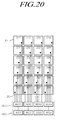
FIG. 20 illustrates exemplary embodiments of the switch circuit and the signal detection circuit of the first electrode driving circuit in the driving circuit of the touch display device according to the present embodiments; -
FIG. 21A to FIG. 21C illustrate signal detection processing for touch sensing and force sensing of the touch display device according to the present embodiments; -
FIG. 22 illustrates exemplary grouping of first electrodes for the purpose of efficient force sensing in touch display device according to the present embodiments; -
FIG. 23 illustrates an exemplary second electrode composed of two or more split electrodes in the touch display device according to the present embodiments; -
FIG. 24 illustrates a method of driving the second electrode composed of split electrodes in the touch display device according to the present embodiments; -
FIG. 25A andFIG. 25B illustrate exemplary partial driving of the second electrode in the touch display device according to the present embodiments; -
FIG. 26 is a flowchart illustrating the method of driving the touch display device according to the present embodiments; -
FIG. 27 to FIG. 30 illustrate exemplary display driving ICs of the touch display device according to the present embodiments. - Reference will now be made in detail to embodiments of the present disclosure, examples of which are illustrated in the accompanying drawings. Throughout this document, reference should be made to the drawings, in which the same reference numerals and signs will be used to designate the same or like components. In the following description of the present disclosure, detailed descriptions of known functions and components incorporated herein will be omitted in the case that the subject matter of the present disclosure may be rendered unclear thereby.
- It will also be understood that, while terms such as "first," "second," "A," "B," "(a)," and "(b)" may be used herein to describe various elements, such terms are only used to distinguish one element from another element. The substance, sequence, order or number of these elements is not limited by these terms. It will be understood that when an element is referred to as being "connected to" or "coupled to" another element, not only can it be "directly connected" or "coupled to" the other element, but it can also be "indirectly connected or coupled to" the other element via an "intervening" element. In the same context, it will be understood that when an element is referred to as being formed "on" or "under" another element, not only can it be directly formed on or under another element, but it can also be indirectly formed on or under another element via an intervening element.
-
FIG. 1 schematically illustrates a touch display device according to exemplary embodiments. - Referring to
FIG. 1 , thetouch display device 100 according to the present embodiments can provide not only a display function to display images, but also a "touch sensing function" to determine whether or not the screen is touched by a pointer, such as a finger or a pen, and/or to detect a touch position (touch coordinates) and a "force sensing function" to detect a level of touch force corresponding to the amount of force (pressure) applied by a user touching the screen. - The term "touch" used herein means an action that the user touches a
display panel 110 with the pointer, such as a finger or a pen. - The touch may be divided into "soft touch" in which the amount of force (pressure) of pressing the
display panel 110 is equal to or less than a predetermined magnitude and "force touch" in which the amount of force (pressure) of pressing thedisplay panel 110 is greater than the predetermined magnitude. - When a soft touch is performed, the
touch display device 100 can determine whether or not the screen is touched and/or detect a touch point (touch coordinates) using the touch sensing function. - When a force touch is performed, the
touch display device 100 can detect the amount of force or pressure (touch force) applied by the user using the force sensing function or the like. - For the touch position sensing function, the pointer must be a pointer, such as a finger or a pen, including a conductor or formed from a conductor. In contrast, for the force sensing function, the pointer may be a pointer formed from not only a conductor, but also a nonconductor. The pointer for the force sensing function may be any type of pointers that can press the screen.
- Referring to
FIG. 1 , thetouch display device 100 according to the present embodiments includes a plurality of first electrodes E1, at least one second electrode E2, and adriving circuit 120. - The plurality of first electrodes E1 form "touch sensors" required to determine whether or not the screen is touched and to detect touch position coordinates. The plurality of first electrodes E1 may be disposed on a touchscreen panel separate from the
display panel 110 or may be disposed within thedisplay panel 110. - When the plurality of first electrodes E1 are disposed within the
display panel 110, thedisplay panel 110 may be referred to as a "touchscreen embedded display panel" within which the plurality of first electrodes E1 functioning as the touch sensors are disposed. - The touchscreen disposed within the
display panel 110 may be an in-cell touchscreen panel or an on-cell touchscreen panel. - The second electrode E2 is an electrode added to sense a level of touch force, and may be located outside (e.g. on the bottom, top, and sides of) the
display panel 110. - In order to sense the touch force, not only the second electrode E2 is operated, but also at least one first electrode E1 among the plurality of first electrodes E1 is operated.
- Thus, in the
touch display device 100 according to the present embodiments, the plurality of first electrodes E1 disposed within thedisplay panel 110 and the second electrode E2 located outside thedisplay panel 110 may be collectively referred to as "force sensors." -
FIG. 2 illustrates three driving operations of thetouch display device 100 according to the present embodiments. - Referring to
FIG. 2 , thetouch display device 100 according to the present embodiments carries out a display driving operation to perform the display function, a touch driving operation to perform the touch sensing function, and a force driving operation to perform the force sensing function. - In a predefined display driving period, the
touch display device 100 according to the present embodiments performs the display driving operation by driving data lines, gate lines, and the like in thedisplay panel 110. - Then, the display function can be provided to the
display panel 110, in which the gradation levels of subpixels are controlled via the data lines and the gate lines to display an intended image. -
FIG. 3 schematically explains the touch sensing method of thetouch display device 100 according to the present embodiments. - Referring to
FIG. 3 , in a predefined touch driving period, thetouch display device 100 performs the touch driving operation to sequentially drive the plurality of first electrodes E1 by sequentially applying touch driving signals TDS to the plurality of first electrodes E1. - Then, the
touch display device 100 can determine whether or not the screen is touched and/or detect a touch position by detecting a change in the capacitance of each of the first electrodes E1 depending on whether or not a capacitance C1 is formed between each of the first electrodes E1 and the pointer, such as a finger, based on signals received from the first electrodes E1 as a result of the touch driving signals TDS. - In the pointer enabling the touch sensing function, a panel contact portion thereof must be formed from a conductor. For example, the pointer may be a finger or a pen, the panel contact portion of which is formed from a conductor.
-
FIG. 4A andFIG. 4B schematically explain the force sensing method of the touch display device according to the present embodiments when a force touch is performed using a pointer, the panel contact portion of which is formed from a conductor.FIG. 5A andFIG. 5B schematically explain the force sensing method of the touch display device according to the present embodiments when a force touch is performed using a pointer, the panel contact portion of which is formed from a nonconductor. - Referring to
FIG. 4A to FIG. 5B , thetouch display device 100 performs the force driving operation by applying a first force driving signal FDS1 to at least one first electrode E1 among the plurality of first electrodes E1 while applying a second force driving signal FDS2 to the second electrode E2. - In the pointer enabling the force sensing function, a panel contact portion thereof may be formed from a conductor or a nonconductor.
- The pointer having the conductive panel contact portion may be, for example, a finger or a pen, the contact portion of which is formed from a conductor. The pointer having the nonconductive panel contact portion may be, for example, a gloved finger or a pen, the contact portion of which is formed from a nonconductor.
- Referring to
FIG. 4A to FIG. 5B , in order to enable the force sensing function of determining the presence of touch force and the amount of touch force, at least one gap G, the size of which is changeable depending on the amount of touch force, must be present between the plurality of first electrodes E1 and the second electrode E2. - The gap G is only required to be present between plurality of first electrodes E1 and the second electrode E2. The position of the gap G may be variously determined depending on the surrounding structures.
- The gap G may be, for example, an air gap or a dielectric gap.
- Referring to
FIG. 4A andFIG. 4B , in response to the force driving operation, the first force driving signal FDS1 is applied to at least one first electrode E1 among the plurality of first electrodes E1 and the second force driving signal FDS2 is applied to the second electrode E2. Then, a first capacitance C1 is formed between the first electrode E1, to which the first force driving signal FDS1 is applied, and the pointer, the panel contact portion of which is formed from a conductor. A second capacitance C2 is formed between the first electrode E1, to which the first force driving signal FDS1 is applied, and the second electrode E2, to which the second force driving signal FDS2 is applied. - The size of the gap G between the first electrode E1 and the second electrode E2 changes depending on the touch force, thereby changing the second capacitance C2 between first electrode E1 and the second electrode E2.
- The
touch display device 100 can perform the force sensing function of determining the presence of touch force and/or the amount of touch force by determining a change in the size of the second capacitance C2 between the first electrode E1 and the second electrode E2, based on signals received from the plurality of first electrodes E1 as a result of the force driving signals FDS1 and FDS2. - Referring to
FIG. 5A andFIG. 5B , in response to the force driving operation, a first force driving signal FDS1 is applied to at least one first electrode E1 of the plurality of first electrodes E1 and a second force driving signal FDS2 is applied to the second electrode E2. Then, no capacitance is formed between the first electrode E1, to which the first force driving signal FDS1, and the pointer, the panel contact portion of which is formed from a nonconductor, whereas a second capacitance C2 is formed between the first electrode E1, to which the first force driving signal FDS1, and the second electrode E2, to which the second force driving signal FDS2 is applied. - The size of the gap G between the first electrode E1 and the second electrode E2 changes depending on the touch force, thereby changing the second capacitance C2 between first electrode E1 and the second electrode E2.
- The
touch display device 100 can perform the force sensing function of determining the presence of touch force and/or the amount of touch force by determining a change in the size of the second capacitance C2 between the first electrode E1 and the second electrode E2, based on signals received from the plurality of first electrodes E1. - As described above, the gap G, structurally formed between the first electrode E1 and the second electrode E2, causes the second capacitance C2 between the first electrode E1 and the second electrode E2 to change depending on the level of touch force, whereby force sensing can be performed based on changes in the capacitance.
-
FIG. 6 illustrates a touch driving signal TDS for the touch sensing function according to the present embodiments. - Referring to
FIG. 6 , in a touch driving period, the touch driving signal TDS applied to a first electrode E1 may be a DC voltage signal or a pulse signal. - Thus, various types of touch driving signals TDS may be used, in consideration of the efficiency of touch driving and the accuracy of touch sensing.
-
FIG. 7A to FIG. 7H illustrate a first force driving signal FDS1 and a second force driving signal FDS2 for the force sensing function according to the present embodiments. - The force sensing function only requires a potential difference to be formed between the first electrode E1 and the second electrode E2.
- In this regard, as illustrated in
FIG. 7A to FIG. 7H , in a force driving period, the first force driving signal FDS1 and the second force driving signal FDS2 applied to the first electrode E1 and the second electrode E2 may have a variety of combinations. - As illustrated in
FIG. 7A andFIG. 7B , the first force driving signal FDS1 and the second force driving signal FDS2 may be pulse signals. - Here, the first force driving signal FDS1 may be a pulse signal, the amplitude of which corresponds to a voltage V1, and the second force driving signal FDS2 may be a pulse signal, the amplitude of which corresponds to a voltage V2. V1 and V2 may be the same voltage or different voltages. When the first force driving signal FDS1 and the second force driving signal FDS2 are pulse signals in reverse phase relationship, V1 and V2 may be the same voltage.
- As illustrated in
FIG. 7C andFIG. 7D , the first force driving signal FDS1 may be a pulse signal, and the second force driving signal FDS2 may be a signal having a second DC voltage. - Here, the first force driving signal FDS1 may be a pulse signal, the width of which corresponds to the voltage V1. The second force driving signal FDS2 may be a signal having the second DC voltage corresponding to a ground voltage or a signal having the second DC voltage corresponding to a second reference voltage Vref2 of the voltage V2.
- As illustrated in
FIG. 7E andFIG. 7F , the first force driving signal FDS1 may be a signal having a first DC voltage, and second force driving signal FDS2 may be a pulse signal. - Here, the first force driving signal FDS1 may be a signal having the first DC voltage corresponding to the ground voltage or a signal having the first DC voltage corresponding to a first reference voltage Vref1 of the voltage V1. The second force driving signal FDS2 may be a pulse signal, the amplitude of which corresponds to the voltage V2.
- As illustrated in
FIG. 7G andFIG. 7H , the first force driving signal FDS1 may be a signal having the first DC voltage, and the second force driving signal FDS2 may be a signal having the second DC voltage. - Here, the first force driving signal FDS1 may be a signal having the first DC voltage corresponding to the ground voltage or a signal having the first DC voltage corresponding to the first reference voltage Vref1 of the voltage V1. The second force driving signal FDS2 may be a signal having the second DC voltage corresponding to the ground voltage or a signal having the second DC voltage corresponding to the second reference voltage Vref2 of the voltage V1.
- The first DC voltage may be the ground voltage GND or the first reference voltage Vref1, which is not the ground voltage GND. The second DC voltage may be the ground voltage GND or the second reference voltage Vref2, which is not the ground voltage GND. The first reference voltage Vref1 and the second reference voltage Vref2 may be the same voltage or different voltages.
- As described above, it is possible to provide efficient force driving using one of a variety of combinations of the first force driving signal FDS1 and the second force driving signal FDS2.
- Among the variety of combinations as mentioned above, in the force driving period F, the first force driving signal FDS1 and the second force driving signal FDS2 may be pulse signals. In this case, as illustrated in
FIG. 7A , the first force driving signal FDS1 and the second force driving signal FDS2 may have an in-phase relationship, in which the phases of the signals are the same. Alternatively, as illustrated inFIG. 7B , the first force driving signal FDS1 and the second force driving signal FDS2 may be in reverse phase relationship, in which the phases of the signals have a phase difference of 180°. - As described above, the phase relationship (in-phase relationship or reverse phase relationship) between the first force driving signal FDS1 and the second force driving signal FDS2, which are pulse signals, can be properly selected considering the signal generating component, the force driving component, and the sensing component, thereby improving the efficiency of the signal generating component, force driving, and sensing.
- As illustrated in
FIG. 7A , in the force driving period F, when the first force driving signal FDS1 and the second force driving signal FDS2 are pulse signals having an in-phase relationship, the second force driving signal FDS2 may be a signal, the phase of which is the same as that of the first force driving signal FDS1, and the amplitude of which is greater than that of the first force driving signal FDS1. - As described above, when the first force driving signal FDS1 and the second force driving signal FDS2, each having the form of a pulse signal, are in the in-phase relationship, the amplitude V2 of the second force driving signal FDS2 may be set greater than the amplitude V1 of the first force driving signal FDS1. Consequently, when the force sensing function is performed based on a signal received from the first electrode E1, it is possible to accurately determine the presence of touch force and/or the amount of touch force by accurately determining whether a corresponding touch is a force touch or a soft touch.
- As illustrated in
FIG. 7G andFIG. 7H , in the force driving period F, when the first force driving signal FDS1 is a signal having the first DC voltage and the second force driving signal FDS2 is a signal having the second DC voltage, the first DC voltage and the second DC voltage may be different voltages. - For example, as illustrated in
FIG. 7G , the first DC voltage may be the ground voltage GND, and the second DC voltage may be the second reference voltage Vref2. Alternatively, as illustrated inFIG. 7H , the first DC voltage may be the first reference voltage Vref1, and the second DC voltage may be the ground voltage GND. - In addition, the first DC voltage may be the first reference voltage Vref1, and the second DC voltage may be the second reference voltage Vref2 different from the first reference voltage Vref1.
- As described above, when the first force driving signal FDS1 is a signal having the first DC voltage and the second force driving signal FDS2 has a signal having the second DC voltage, the first DC voltage and the second DC voltage may be set different. This consequently enables the force sensing function even in the case in which the force driving operation is simply performed using the first force driving signal FDS1 and the second force driving signal FDS2, each having the form of a pulse signal.
-
FIG. 8A is an exemplary view of the drivingcircuit 120 of thetouch display device 100 in force driving period according to the present embodiments. - As illustrated in
FIG. 8A , the drivingcircuit 120 includes a first force drivingsignal provider 810, a second force drivingsignal provider 820, anintegrator 830, an analog-digital converter ADC, and aprocessor 840. The first force drivingsignal provider 810 supplies a first force driving signal FDS1 having one of the signal waveforms illustrated inFIG. 7A to FIG. 7H to the first electrode E1 by on/off control of two switches SW1 and SW10. The second force drivingsignal provider 820 supplies the second force driving signal FDS2 having one of the signal waveforms illustrated inFIG. 7A to FIG. 7H to the second electrode E2 by on/off control of the switches SW1 and SW10. Theintegrator 830 includes an operation amplifier OP-AMP, a capacitor C, and a resistor R, and produces an output value by integrating an input. The analog-digital converter ADC converts the value output by the integrator to a digital value. Theprocessor 840 calculates touch position coordinates and senses touch force based on the digital value output by the analog-digital converter ADC. - At least one of the analog-digital converter ADC and the
processor 840 may be disposed outside the drivingcircuit 120. - The circuit configuration of the driving
circuit 120 illustrated inFIG. 8A is illustrative only and may be embodied in a variety of forms. - Referring to
FIG. 8A , in the force driving operation, the drivingcircuit 120 applies the first force driving signal FDS1 to at least one first electrode E1 among the plurality of first electrodes E1 and applies the second force driving signal FDS2 to the second electrode E2. The drivingcircuit 120 determines a change in the second capacitance C2 between the corresponding first electrode E1 or a group of the first electrodes E1 and the second electrode E2 by sensing a charge level (or a voltage) depending on a change in the size of the gap G between the corresponding first electrode E1 or the group of the first electrodes E1 and the second electrode E2, based on a signal (an input of the integrator 830) received from each of the first electrodes E1 or the group of the first electrodes E1, thereby determining the presence and/or the amount of touch force of a touch. - Referring to
FIG. 8A , a signal (an input of the integrator 830) received from each of the first electrodes E1 or the group of the first electrodes E1 corresponds to a total of charges Q1+Q2 of a charge Q1 charged in a capacitor C1 between the pointer and the first electrode E1 and a charge Q2 charged in a capacitor C2 between the first electrode E1 and the second electrode E2. - The total of charges Q1+Q2 is charged in a capacitor C within the
integrator 830 and is output as a sensing voltage Vsen from theintegrator 830. - Then, the analog-digital converter ADC converts the sensing voltage Vsen to a digital value.
- The
processor 840 can determine the presence and/or amount of touch force based on the digital value output to the analog-digital converter ADC. - When the generation of touch force is determined, an application or a function, previously set in correspondence to the touch force, can be performed.
- Alternatively, when the amount of touch force is determined, an application or a function, previously set in correspondence to the amount of touch force, can be performed.
-
FIG. 8B is an exemplary view of the driving circuit of the touch display device in touch driving period according to the present embodiments. - Referring to
FIG. 8B , in the touch driving operation, the drivingcircuit 120 applies the touch driving signal TDS to at least one first electrode E1 among the plurality of first electrodes E1. The drivingcircuit 120 determines a change in the second capacitance C1 between the corresponding first electrode E1 or a group of the first electrodes E1 and pointer (etc. finger), based on a signal (an input of the integrator 830) received from each of the first electrodes E1 or the group of the first electrodes E1, thereby determining the position of a touch. - The touch driving signal TDS is generated by alternate on/off control two switches SW1 and SW10(SW1=OFF, SW10=ON -> SW1=ON, SW10=OFF -> SW1=OFF, SW10=ON -> ...... ). The touch driving signal TDS is a pulse signal with a desired amplitude (ex. if V0=0 [volt], amplitude=V1 [volt]).
- The touch driving signal TDS may be same or similar as the first force driving signal FDS1 for the first electrodes E1.
- In the touch driving operation, two switches SW2 and SW20 become off-state. So, No voltage is applied to the second electrode E2. That is, the second electrode E2 becomes floating state. The second capacitance C2 is not formed between the corresponding first electrode E1 or a group of the first electrodes E1 and the second electrode E2.
- Referring to
FIG. 8B , a signal (an input of the integrator 830) received from each of the first electrodes E1 or the group of the first electrodes E1 corresponds to a charge Q1 charged in a capacitor C1 between the pointer and the first electrode E1. - The charges Q1 is charged in a capacitor C within the
integrator 830 and is output as a sensing voltage Vsen from theintegrator 830. - Then, the analog-digital converter ADC converts the sensing voltage Vsen to a digital value.
- The
processor 840 can determine the position of a touch based on the digital value output to the analog-digital converter ADC. - Hereinafter, reference will be made to the characteristics of incoming signals discriminatively generated in response to a soft touch and a force touch as the
touch display device 100 according to the present embodiments performs the force driving operation such that the soft touch and the force touch can be distinguished. -
FIG. 9 illustrates the intensity of an incoming signal in response to a soft touch and the intensity of an incoming signal in response to a force touch in thetouch display device 100 according to the present embodiments.FIG. 10A andFIG. 10B illustrate the intensity distribution of the incoming signals in response to a soft touch and a force touch in thetouch display device 100 according to the present embodiments. - Here,
FIG. 9 ,FIG. 10A , andFIG. 10B are based on the assumption that the first force driving signal FDS1 and the second force driving signal FDS2 are pulse signals as illustrated inFIG. 7A andFIG. 7B . - Referring to
FIG. 9 , the intensity of a signal received from the first electrode E1 may be determined based on digital values output from the analog-digital converter ADC. - Referring to
FIG. 9 , in the case of a soft touch, in which the amount of pressing force is equal to or less than a predetermined magnitude, digital values output from the analog-digital converter ADC have positive (+) values with respect to a digital value output from the analog-digital converter ADC when there is no touch (baseline). - Referring to
FIG. 9 , when the second force driving signal FDS2 is in-phase with the first force driving signal FDS1, digital values output from the analog-digital converter ADC in the case of a force touch, in which the amount of pressing force exceeds the predetermined magnitude, have negative (-) values with respect to a digital value output from the analog-digital converter ADC when there is no touch (baseline). - Referring to
FIG. 9 , when the second force driving signal FDS2 is in the reverse phase relationship with the first force driving signal FDS1, digital values output from the analog-digital converter ADC in the case of a force touch, in which the amount of pressing force exceeds the predetermined magnitude, have positive (+) values with respect to a digital value output from the analog-digital converter ADC when there is no touch (baseline) and is greater than a digital value output from the analog-digital converter ADC in the case of a soft touch, in which the amount of pressing force is equal to or less than a predetermined magnitude. - As illustrated in
FIG. 10A , in the case of a soft touch, the magnitudes of digital values (signal intensity) output from the analog-digital converter ADC are distributed such that the signal intensity generally increases in the positive (+) direction of the z axis based on the baseline. - In addition, as illustrated in
FIG. 10A , referring to the distribution of signal intensity in the case of a soft touch, higher values of signal intensity may be concentrated in a location of the entire screen area where the soft touch has occurred. - As illustrated in
FIG. 10B , when the second electrode E2 is assumed to be an integral plate when viewed from the outside of thedisplay panel 110, in the case of a force touch, the magnitudes of digital values (signal intensity) output from the analog-digital converter ADC are distributed such that the signal intensity generally increases in the negative (-) direction of the z axis based on the baseline. - In addition, as illustrated in
FIG. 10B , in the case of a force touch, signal intensities are distributed such that the signal intensity at the center point of the screen is greatest in the negative (-) direction and the signal intensity gradually increases from the periphery toward the center of the screen. - As the force touch becomes stronger, the change in the size of the gap G between the plurality of first electrodes E1 and the second electrode E2 increases. Consequently, digital value outputs from the analog-digital converter ADC have a greater value in the negative (-) direction of the z axis based on a digital value output from the analog-digital converter ADC when there is no touch (baseline). That is, the stronger the force touch is, the greater the signal intensity becomes.
-
FIG. 11A andFIG. 11B schematically illustrate a force sensing structure of thetouch display device 100 according to the present embodiments. - Referring to
FIG. 11A , thetouch display device 100 according to the present embodiments includes a plurality of first electrodes E1 disposed within adisplay panel 110 and a second electrode E2 disposed outside (e.g. below) thedisplay panel 110. Each first electrode E1 is a common electrode for a corresponding plurality of pixels (not shown). - In addition, a gap G, the size of which is changeable in response to a force touch, is formed between the plurality of first electrodes E1 and the second electrode E2, such that force sensing is possible.
- In this regard, the
touch display device 100 according to the present embodiments includes agap structure unit 1000 forming the gap G between the plurality of first electrodes E1 and the second electrode E2. Thegap structure unit 1000 allows the size of the gap G to change in response to the force touch. - The
gap structure unit 1000 enables the force sensing function. - The shape (e.g. a frame shape) of the
gap structure unit 1000 corresponds to the outline shape of thedisplay panel 110. - The
gap structure unit 1000 may be a separate structure or may be embodied by using an existing structure such as a guide panel. - The
touch display device 100 according to the present embodiments may be a range of display devices, such as a liquid crystal display (LCD) device or an OLED display device. - Hereinafter, for the sake of brevity, the
touch display device 100 according to the present embodiments will be assumed to be an LCD device. - Referring to
FIG. 11B , in thetouch display device 100 according to the present embodiments, thedisplay panel 110 includes afirst substrate 1110 on which thin-film transistors (TFTs) and the like are disposed and asecond substrate 1120 on which color filters (CFs) and the like are disposed. - A
driving chip 1130 may be disposed on, bonded to, or connected to the peripheral portion (non-active area) of thefirst substrate 1110. - The
driving chip 1130 may be a chip in which a data driving circuit is formed, a chip including a firstelectrode driving circuit 1310 within the drivingcircuit 120, or a chip including a data driving circuit and the firstelectrode driving circuit 1310. In some cases, thedriving chip 1130 may be a chip including the drivingcircuit 120. - Referring to
FIG. 11B , alower structure 1100 is disposed below thedisplay panel 110. - The
gap structure unit 1000 may be disposed below, within, or on one side of thelower structure 1100. - The second electrode E2 is disposed below the
gap structure unit 1000. - The second electrode E2 may be positioned below or within the
lower structure 1100 of thedisplay panel 110. - As described above, the position of the second electrode E2 or the position of the
gap structure unit 1000 is variously designed. Thus, the force sensor structure can be designed to be suitable to the designed structures of thedisplay panel 110 and the display device. -
FIG. 12A is a cross-sectional view of thetouch display device 100 having the force sensing structure according to the present embodiments, andFIG. 12B illustrates a situation in which the size of the gap G changes in response to a force touch. - Referring to
FIG. 12A , thedisplay panel 110 includes afirst polarization plate 1210, afirst substrate 1110, a plurality of first electrodes E1, asecond substrate 1120, and asecond polarization plate 1220. - A
bonding layer 1230 and anupper cover 1240 are disposed on the upper part of thedisplay panel 110. - A
lower structure 1100 is disposed on the lower part of thedisplay panel 110. - The
lower structure 1100 may be a structure that is a part of the display device or a separate structure provided for a second electrode E2. - For example, the
lower structure 1100 may be a backlight unit or a rear cover of the LCD device. - In addition, the
lower structure 1100 may be any structure that can form a capacitor between each of the first electrodes E1 and the second electrode E2. - Referring to
FIG. 12A , for example, thegap structure unit 1000 has the shape of a frame, and is situated between the periphery of the rear surface of thedisplay panel 110 and the periphery of the second electrode E2. - In addition, the
lower structure 1100, such as a backlight unit, is situated in a space between the rear surface of the display panel 110 (the rear surface of the first polarization plate 1210) and the second electrode E2, defined by thegap structure unit 1000. - A gap G, such as an air gap or a dielectric gap, is present between the rear surface of the display panel 110 (the rear surface of the first polarization plate 1210) and the
lower structure 1000. - Referring to
FIG. 12b , in the case of a force touch, theupper cover 1240, thedisplay panel 110, and the like are slightly warped downward. - This consequently changes the size of the gap g, such as an air gap or a dielectric gap, disposed between the first electrodes E1 and the second electrode E2.
- When the gap G prior to the force touch is designated with G1 and the gap G after the force touch is designated with G2, G2 is reduced to be smaller than G1 in response to the touch force.
- With the gap G being reduced from G1 to G2 after the force touch, a second capacitance C2 is changed, whereby the force touch can be recognized.
-
FIG. 13A andFIG. 13B illustrate the drivingcircuit 120 of thetouch display device 100 according to the present embodiments. - Referring to
FIG. 13A andFIG. 13B , the drivingcircuit 120 of thetouch display device 100 according to the present embodiments is a circuit able to improve both the touch sensing function and the force sensing function. - The driving
circuit 120 includes asignal generating circuit 1300, a firstelectrode driving circuit 1310, a secondelectrode driving circuit 1320, and adetection processor 1330. - The
signal generating circuit 1300 generates and outputs a touch driving signal TDS and a first force driving signal FDS1. -
FIG. 13A andFIG. 13B illustrate two drivingcircuits 120 depending on whether or not a second force driving signal FDS2 is generated by thesignal generating circuit 1300. - Specifically,
FIG. 13A illustrates the drivingcircuit 120 in which thesignal generating circuit 1300 generates and outputs not only the touch driving signal TDS and the first force driving signal FDS1, but also the second force driving signal FDS2.FIG. 13B illustrates the drivingcircuit 120 in which thesignal generating circuit 1300 generates and outputs the touch driving signal TDS and the first force driving signal FDS1 without generating the second force driving signal FDS2. - In a touch driving period T, the first
electrode driving circuit 1310 receives the touch driving signal TDS from thesignal generating circuit 1300 and sequentially applies the touch driving signal TDS to at least one first electrode among the plurality of first electrodes E1. In a force driving period F, the firstelectrode driving circuit 1310 receives the first force driving signal FDS1 from thesignal generating circuit 1300 and applies the first force driving signal FDS1 to at least one first electrode among the plurality of first electrodes E1. - The first
electrode driving circuit 1310 includes anintegrator 830 and an analog-digital converter ADC, as illustrated inFIG. 8A . - In the force driving period F, the second
electrode driving circuit 1320 applies the second force driving signal FDS2 to the second electrode E2 positioned outside thedisplay panel 110. - The use of the above-described
driving circuit 120 enables not only the touch sensing function of determining whether or not the screen is touched and/or detecting a touch point, but also the force sensing function of determining the presence and/or amount of touch force. - Referring to
FIG. 13A , thesignal generating circuit 1300 can also generate and output the second force driving signal FDS2. Then, the secondelectrode driving circuit 1320 transfers the second force driving signal FDS2, output from thesignal generating circuit 1300, to the second electrode E2. - As described above, since the
signal generating circuit 1300 generates and outputs not only the first force driving signal FDS1, but also the second force driving signal FDS2, the use of the second force driving signal FDS2 different from the first force driving signal FDS1 facilitates the force driving operation. - Referring to
FIG. 13B , since thesignal generating circuit 1300 does not generate the second force driving signal FDS2, the drivingcircuit 120 further includes asignal converter 1340 that generates the second force driving signal FDS2 by converting at least one of the amplitude, the phase, and the like of the first force driving signal FDS1 generated by thesignal generating circuit 1300. - With this configuration, the
signal generating circuit 1300 is required only to generate the first force driving signal FDS1. The signaling load of thesignal generating circuit 1300 is reduced. For the purpose of effective force driving and force sensing, the second force driving signal FDS2 matching the first force driving signal FDS1 can be generated. - For example, the
signal converter 1340 may include a level shifter to adjust the voltage level of a signal, may include a phase controller to control the phase of a signal, and/or may include a DA converter to convert a DC signal to an AC signal (e.g. a pulse signal) or an AD converter to convert an AC signal (e.g. a pulse signal) to a DC signal. Thesignal converter 1340 may be implemented as the secondelectrode driving circuit 1320 or may be included in the secondelectrode driving circuit 1320. - In the touch driving period T, the first
electrode driving circuit 1310 receives a touch sensing signal generated in response to the touch driving signal TDS, and generates digital data from the received signal. Thedetection processor 1330 receives the digital data and determines whether or not the screen is touched and detects a touch position from the digital data. - In the force driving period F, the first
electrode driving circuit 1310 receives a touch sensing signal generated in response to the force driving signals FDS1 and FDS2, and generates digital data from the received signal. Thedetection processor 1330 receives the digital data and detects a level of touch force from the digital data. - The
detection processor 1330 may be a component corresponding to theprocessor 840 inFIG. 8A andFIG. 8B , and may be a micro controller unit (MCU). - As described above, the
detection processor 1330 performs not only the touch sensing function but also the force sensing function by receiving data from the firstelectrode driving circuit 1310 that corresponds to signals from the first electrodes E1, whereby the two sensing functions can be efficiently performed using the same processing method. - The
signal generating circuit 1300 may be implemented as a power integrated circuit (IC). - The
signal generating circuit 1300 and the firstelectrode driving circuit 1310 may be included in a single IC. In some cases, thesignal generating circuit 1300, the firstelectrode driving circuit 1310, and thedetection processor 1330 may be included in a single IC. -
FIG. 14A andFIG. 14B illustrate signal supply structures of thetouch display device 100 according to the present embodiments. -
FIG. 14A andFIG. 14B illustrate thetouch display device 100, in which thelower structure 1100 is abacklight unit 1400, including a first printedcircuit 1420 and a second printedcircuit 1430. The first printedcircuit 1420 transfers signals to thedisplay panel 110, and the second printedcircuit 1430 transfers signals to a backlight driver within thebacklight unit 1400. -
FIG. 14A is an exemplary embodiment ofFIG. 13A , andFIG. 14B is an exemplary embodiment ofFIG. 13B . - Referring to
FIG. 14A andFIG. 14B , the secondelectrode driving circuit 1320 includes one or more of the printedcircuits signal generating circuit 1300 and the second electrode E2, as a component for transferring a second force driving signal. - That is, the printed
circuits - As described above, one or more of the printed
circuits electrode driving circuit 1320 to transfer the second force driving signal FDS2 in the force driving operation. Accordingly, it is unnecessary to form an additional circuit, and a compact signal transfer structure can be formed using one or more of the printedcircuits - More specifically, by way of example, referring to
FIG. 14A andFIG. 14B , the first printedcircuit 1420 receiving the first force driving signal FDS1 output from thesignal generating circuit 1300 is connected to a peripheral portion of thedisplay panel 110, whereby the first printedcircuit 1420 is electrically connected to thedriving chip 1130. - The first and second printed
circuits - The second printed
circuit 1430 has a terminal PA connected to the first printedcircuit 1420. - The terminal PA of the second, flexible printed
circuit 1430 has not only a pin to receive a signal for the driving of thebacklight unit 1400, but also a touch force sensing drivingpin 1431 to receive the second force driving signal FDS2 from the first printedcircuit 1420. - The touch force sensing driving
pin 1431 allows the second force driving signal FDS2 to be transferred from the first printedcircuit 1420 to the second printedcircuit 1430. - As described above, in order to transfer the second force driving signal FDS2, necessary for the driving of the second electrode E2 for the force sensing function, from the first printed
circuit 1420 to the second printedcircuit 1430, the first printedcircuit 1420 and the second printedcircuit 1430 are connected via the dedicated touch force sensing drivingpin 1431 using the pin contact method. The first printedcircuit 1420 and the second printedcircuit 1430 can be easily connected, and signals can be accurately transferred. - The first printed
circuit 1420 and the second printedcircuit 1430 may be directly connected via contact terminals, or may be electrically connected via a connecting medium 1440, such as a wire, a conductive tape, or a conductive pattern electrode. - Hereinafter, reference will be made to points in time for the three driving operations (display driving, touch driving, and force driving) of the
touch display device 100. -
FIG. 15 illustrates three driving periods of thetouch display device 100 according to the present embodiments and signals applied to a first electrode E1 and a second electrode E2 depending on driving periods. - Referring to
FIG. 15 , a display driving period D, a touch driving period T, and a force driving period F may be divided by time division. - In the display driving period D, the driving
circuit 120 supplies a display driving voltage (e.g. a common voltage Vcom) to a plurality of first electrodes E1. - In the touch driving period T, the driving
circuit 120 applies a touch driving signal TDS to at least one first electrode among the plurality of first electrodes E1. - In the force driving period F, the driving
circuit 120 applies a first force driving signal FDS1 to at least one first electrode among the plurality of first electrodes E1 and applies a second force driving signal FDS2 to the second electrode E2. - Even in the case in which all of the first electrodes E1 are used for both the display driving operation, the touch driving operation, and the force driving operation, the display driving period D, the touch driving period T, and the force driving period F are divided and allocated by time division, such that the three driving operations (display driving, touch driving, and force driving) can be accurately performed without confusion or interference.
- Hereinafter, exemplary methods of allocating the display driving period D, the touch driving period T, and the force driving period F to frame periods will be described.
-
FIG. 16A to FIG. 16C illustrate a first method of allocating three driving periods in thetouch display device 100 according to the present embodiments, andFIG. 17A to FIG. 17E illustrate a second method of allocating three driving periods in thetouch display device 100 according to the present embodiments. - Referring to
FIG. 16A to FIG. 16C , the first allocation method allocates one display driving period D and one touch driving period T to every frame period and allocates one force driving period F to at least every second frame period. - Referring to
FIG. 16A , according to the first allocation method, in at least one frame period among a plurality of frame periods, one display driving period D, one touch driving period T, and one force driving period F are divided by time division. - Referring to
FIG. 16B , one display driving period D, one touch driving period T, and one force driving period F are controlled based on a synchronization signal SYNC, provided from a controller (not shown) such as a timing controller to thedriving circuit 120. - That is, the driving
circuit 120 can perform the display driving operation, the touch driving operation, and the force driving operation in corresponding fractions of time, based on the synchronization signal SYNC received from the controller (not shown). - Referring to
FIG. 16B , in the synchronization signal SYNC, a higher level fraction (or a lower level fraction) corresponds to the display driving period D, a lower level fraction (or a higher level fraction) corresponds to the touch driving period T. - In the synchronization signal SYNC, the force driving period F starts after the lapse of a fraction of time in which the lower level fraction defined as the touch driving period T.
- Referring to
FIG. 16B , the display driving period D, the touch driving period T, and the force driving period F are defined using the single synchronization signal SYNC. - Alternatively, the display driving period D and the touch driving period T may be defined using a first synchronization signal, and the force driving signal F may be defined using a second synchronization signal (
FIG. 17C ). - As illustrated in
FIG. 16C , the force sensing period F may not be present in every frame period but may be present in at least every second frame period. - In addition, in
FIG. 16A to FIG. 16C , the orders of the display driving period D, the touch driving period T, and the force driving period F may be variously designed. - Furthermore, in
FIG. 16A to FIG. 16C , one display driving period D, one touch driving period T, and two or more force driving periods F may be present in a single frame period. - For example, a single frame period may be designed in the order of the display driving period D, the force driving period F, and the touch driving period T.
- Referring to
FIG. 17A to FIG. 17E , the second allocation method allocates two or more display periods D and two or more touch driving periods T to every frame period and allocates one force driving period F to every or every second frame period. - Referring to
FIG. 17A , in at least one frame period among a plurality of frame periods, at least n number of touch driving periods T1, T2, ..., and Tn (where n is a natural number equal to or greater than 2) and m number of force driving periods F1, ..., and Fm (where m is a natural number equal to or greater than 1) are divided by time division. - Referring to
FIG. 17B , for example, n+m number of display driving periods D1, D2, ..., Dn, Dn+1, ..., and Dn+m, at least n number of touch driving periods T1, T2, ..., and Tn, and m number of force driving periods F1, ..., and Fm in a single frame period are controlled based on a synchronization signal SYNC. - Referring to
FIG. 17C , in a single frame period, n+m number of display driving periods D1, D2, ..., Dn, Dn+1, ..., and Dn+m and at least n number of touch driving periods T1, T2, ..., and Tn are controlled based on a first synchronization signal SYNC1, and m number of force driving periods F1, ..., and Fm are controlled based on a second synchronization signal SYNC2. -
FIG. 17D illustrates a case in which two display driving periods D1 and D2 and two touch driving periods T1 and T2 alternate in a single frame period and one force driving period F is present in the last part of the frame period. - Here, the force driving period F may be positioned any location between the two display driving periods D1 and D2 and the two touch driving periods T1 and T2 (e.g. "D1, T1, D2, T2, F", "D1, T1, D2, F, T2", and "D1, T1, F, D2, T2").
-
FIG. 17E illustrates a case in which three display driving periods D1, D2, and D3 and two touch driving periods T1 and T2 alternate in a single frame period and one force driving period F is present in the last part of the frame period. - Here, the force driving period F may be positioned any location between the three display driving periods D1, D2, and D3 and the two touch driving periods T1 and T2 (e.g. "D1, T1, D2, T2, D3, F", "D1, T1, D2, T2, F, D3", "D1, T1, D2, F, T2, D3", and "D1, T1, F, D2, T2, D3").
- Referring to
FIG. 16A to FIG. 16C andFIG. 17A to FIG. 17E , one frame period includes at least one display driving period D. One or more touch driving periods T are present in every frame period. That is, the display driving period D can be present in every frame period. Although one or more touch driving periods T may be present in every frame period as illustrated in the drawings, one or more touch driving periods T may be present in at least every second frame period instead of being present in every frame period. - Referring to
FIG. 16A to FIG. 16C andFIG. 17A to FIG. 17E , one or more force driving periods F are present in at least every second frame period. - A driving frequency for touch driving and a driving frequency for force driving may be lower than a driving frequency for display driving.
- In addition, the
touch display device 100 operates in active mode when there is an external input (a user input, a data input, etc.) and operates in idle mode (also referred to as "sleep mode") when there is no external input. - When the
touch display device 100 operates in the idle mode, it is possible to set driving frequencies for the display driving operation, the touch driving operation, and the force driving operation to be lower than the driving frequency of active mode in order to reduce power consumption. - As described above, when the display driving period D, the touch driving period T, and the force driving period F are divided in time, one allocation method can be selected from a variety of allocation methods for the display driving period D, the touch driving period T, and the force driving period F, by comprehensively considering display performance, touch sensing performance, and force sensing performance, whereby an optimum driving method can be designed.
- In the touch driving period T, when a touch driving signal TDS is applied to one first electrode of the first electrodes E1, a parasitic capacitance may be formed between the first electrode E1 and an adjacent electrode or portion.
- For example, a parasitic capacitance may be formed between the first electrode E1 and a data line, may be formed between the first electrode E1 and a gate line, or may be formed between the first electrode E1 and another first electrode E1. In addition, a parasitic capacitance may be formed between the first electrode E1 and the second electrode E2.
- When a touch is sensed based on a change in the capacitance between the first electrode E1 and the pointer, a parasitic capacitance formed between the first electrode E1 and the adjacent electrode may significantly lower the accuracy of touch sensing, as described above.
- In order to overcome this problem, the
touch display device 100 according to the present embodiments may operate with no load (load-free driving). - The load-free driving is a method of driving the surrounding electrode(s) of the first electrode in order to prevent a parasitic capacitance from being formed between the first electrode E1 and the surrounding electrode(s).
-
FIG. 18A andFIG. 18B illustrate load-free driving of thetouch display device 100 according to the present embodiments. - Referring to
FIG. 18A andFIG. 18B , when the drivingcircuit 120 sequentially applies a touch driving signal TDS to at least one first electrode among the plurality of first electrodes E1 in a touch driving period T, a touch driving signal TDS or a load-free driving signal LFDS may be applied to the second electrode E2, the load-free driving signal being in-phase with the touch driving signal TDS. - The load-free driving signal LFDS may be a touch driving signal TDS simultaneously applied to the first electrode E1 and the second electrode E2.
- Alternatively, the load-free driving signal LFDS may be a separate signal in-phase with the touch driving signal TDS. In this case, the load-free driving signal LFDS and the touch driving signal TDS may have the same voltage and the same amplitude.
- Thus, as described above, when the touch driving signal TDS is applied to the first electrode E1 in the touch driving period T, an application of the touch driving signal TDS or the load-free driving signal LFDS, in-phase with the touch driving signal TDS, to the second electrode E2 can prevent a parasitic capacitance from being formed between the first electrode E1 and the second electrode E2. This can consequently improve the accuracy of touch sensing.
- As described above, when the touch driving signal TDS is applied to the first electrode E1 in the touch driving period T, the touch driving signal TDS or the load-free driving signal LFDS, in-phase with the touch driving signal TDS, may be applied to the entire data lines or the surrounding data line(s).
- When the touch driving signal TDS is applied to the first electrode E1 in the touch driving period T, the touch driving signal TDS or the load-free driving signal LFDS, in-phase with the touch driving signal TDS, may be applied to the entire gate lines or the surrounding gate line(s).
- When the touch driving signal TDS is applied to the first electrode E1 in the touch driving period T, the touch driving signal TDS or the load-free driving signal LFDS, in-phase with the touch driving signal TDS, may be applied to the entire first electrodes E1 or the surrounding first electrode(s) E1.
-
FIG. 19 illustrates aswitch circuit 1910 and asignal detection circuit 1920 of the firstelectrode driving circuit 1310 in thedriving circuit 120 of thetouch display device 100 according to the present embodiments, andFIG. 20 illustrates exemplary embodiments of theswitch circuit 1910 and thesignal detection circuit 1920 of the firstelectrode driving circuit 1310 in thedriving circuit 120 of thetouch display device 100 according to the present embodiments. - Referring to
FIG. 19 , in order to selectively supply a display driving voltage (e.g. Vcom), a touch driving signal TDS, and a first force driving signal FDS1 to the first electrodes E1 according to the three driving periods D, T, and F, the firstelectrode driving circuit 1310 includes theswitch circuit 1910 and thesignal detection circuit 1920. Theswitch circuit 1910 selects all or some of signal lines SL connected to the plurality of first electrodes E1 as a signal line SL through which the display driving voltage (e.g. Vcom), the touch driving signal TDS, and the first force driving signal FDS1 are supplied. Thesignal detection circuit 1920 detects signals through the first electrodes E1 connected to theswitch circuit 1910. - The
switch circuit 1910 includes one or more multiplexers. - The
signal detection circuit 1920 includes one or more analog front ends (AFEs). - As illustrated in
FIG. 19 andFIG. 20 , twenty-four first electrodes E1 (S11, S12, S13, S14, S21, S22, S23, S24, ..., S61, S62, S63, and S64) are arranged in a matrix of six rows and four columns. In the interests of driving efficiency, for example, theswitch circuit 1910 includes four multiplexers MUX1, MUX2, MUX3, and MUX4, and thesignal detection circuit 1920 includes four analog front ends AFE1, AFE2, AFE3, and AFE4. -
FIG. 21A to FIG. 21C illustrate the signal detection processing for touch sensing and force sensing of the touch display device according to the present embodiments. - Referring to
FIG. 21A , in the touch driving operation, at a point in time t1, a touch driving signal TDS is simultaneously applied to the four first electrodes S11, S12, S13, and S14 in the first row through the four multiplexers MUX1, MUX2, MUX3, and MUX4, and the four analog front ends AFE1, AFE2, AFE3, and AFE4 detect an incoming signal through the four first electrodes S11, S12, S13, and S14 in the first row. - In the same manner, at a point in time t2, a touch driving signal TDS is simultaneously applied to the four first electrodes S21, S22, S23, and S24 in the second row through the four multiplexers MUX1, MUX2, MUX3, and MUX4, and the four analog front ends AFE1, AFE2, AFE3, and AFE4 detect an incoming signal through the four first electrodes S21, S22, S23, and S24 in the second row.
- Likewise, at a point in time t3, the four first electrodes S31, S32, S33, and S33 in the third row are subjected to touch driving and signal sensing. At a point in time t4, the four first electrodes S41, S42, S43, and S43 in the fourth row are subjected to touch driving and signal sensing. At a point in time t5, the four first electrodes S51, S52, S53, and S53 in the fifth row are subjected to touch driving and signal sensing. In addition, at a point in time t6, the four first electrodes S61, S62, S63, and S63 in the sixth row are subjected to touch driving and signal sensing.
- Touch sensing may be performed based on all incoming signals detected using the above-described method.
- Referring to
FIG. 21B , in the force driving period, at a point in time t1, a first force driving signal FDS1 is simultaneously applied to the four first electrodes S11, S12, S13, and S14 in the first row through the four multiplexers MUX1, MUX2, MUX3, and MUX4, and the four analog front ends AFE1, AFE2, AFE3, and AFE4 detect an incoming signal (force data) through the four first electrodes S11, S12, S13, and S14 in the first row. - In the same manner, at a point in time t2, a first force driving signal FDS1 is simultaneously applied to the four first electrodes S21, S22, S23, and S24 in the second row through the four multiplexers MUX1, MUX2, MUX3, and MUX4, and the four analog front ends AFE1, AFE2, AFE3, and AFE4 detect an incoming signal through the four first electrodes S21, S22, S23, and S24 in the second row.
- Likewise, at a point in time t3, the four first electrodes
- S31, S32, S33, and S33 in the third row are subjected to force driving and signal sensing. At a point in time t4, the four first electrodes S41, S42, S43, and S43 in the fourth row are subjected to force driving and signal sensing. At a point in time t5, the four first electrodes S51, S52, S53, and S53 in the fifth row are subjected to force driving and signal sensing. In addition, at a point in time t6, the four first electrodes S61, S62, S63, and S63 in the sixth row are subjected to force driving and signal sensing.
- As described above, force sensing may be performed based on all incoming signals detected during force driving at the points in time t1 to t6.
- That is, in the force driving period F, the driving
circuit 120 can sense a level of touch force by determining a change in the capacitance between each of the first electrodes E1 and the second electrode E2, based on the signals received from the first electrodes E1. - As described above, the entire changes in the capacitance formed between the first electrodes E1 and the second electrode E2 are determined, such that precise force sensing can be performed.
- Referring to
FIG. 21C , for the purpose of force driving and sensing efficiency, the twenty-four first electrodes E1 (S11, S12, S13, S14, S21, S22, S23, S24, ..., S61, S62, S63, and S64), arranged in six rows and four columns, are grouped in columns. In this case, the twenty-four first electrodes E1 (S11, S12, S13, S14, S21, S22, S23, S24, ..., S61, S62, S63, and S64) are grouped into four groups of first electrodes G1, G2, G3, and G4. - With this configuration, the six signal lines SL connected to the six first electrodes S11, S21, ..., S61 of the first group of first electrodes G1 in the first column are electrically connected by means of the first multiplexer MUX1.
- Thus, in the force driving period F, a first force driving signal FDS1 is simultaneously applied to the six first electrodes S11, S21, ..., S61 of the first group of first electrodes G1 in the first column.
- In the same manner, the first force driving signal FDS1 is simultaneously applied to the six first electrodes S12, S22, ..., and S62 of the second group of first electrodes G2 in the second column. Likewise, the first force driving signal FDS1 is simultaneously applied to the six first electrodes S13, S23, ..., and S63 of the third group of first electrodes G3 in the third column. In addition, the first force driving signal FDS1 is simultaneously applied to the six first electrodes S14, S24, ..., and S64 of the fourth group of first electrodes G4 in the fourth column.
- Consequently, the first force driving signal FDS1 can be simultaneously applied to the twenty-four first electrodes E1 (S11, S12, S13, S14, S21, S22, S23, S24, ..., S61, S62, S63, and S64).
- The force driving time can be reduced to about 1/6 compared to the case in
FIG. 21b . - In addition, the six signal lines SL, connected to the six first electrodes S11, S21, ..., and S61 of the first group of first electrodes G1 in the first column due to column grouping, are electrically connected by means of the first multiplexer MUX1.
- Thus, the analog front end AFE1 can detect a signal received from the first group of first electrodes G1 including the six first electrodes S11, S21, ..., and S61 arranged in the first column.
- In this manner, the second analog front end AFE2 can detect a signal received from the second group of first electrodes G2 including the six first electrodes S12, S22, ..., and S62 arranged in the second row. The third analog front end AFE3 can detect a signal received from the third group of first electrodes G3 including the six first electrodes S13, S23, ..., and S63 arranged in the third row. In addition, the fourth analog front end AFE4 can detect a signal received from the fourth group of first electrodes G4 including the six first electrodes S14, S24, ..., and S64 arranged in the fourth row.
- Signal detection using the four analog front ends AFE1, AFE2, AFE3, and AFE4 can be simultaneously performed. Thus, signal detection time can be reduced to about 1/6 compared to the case in
FIG. 21b . - After the signal detection, in the force driving period F, the driving
circuit 120 can sense a level of touch force by determining changes in the capacitance between the groups of first electrodes G1, G2, G3, and G4 and the second electrode E2, based on a signal received from the groups of first electrodes G1, G2, G3, and G4. -
FIG. 22 illustrates exemplary grouping of first electrodes for the purpose of efficient force sensing intouch display device 100 according to the present embodiments. -
FIG. 22 illustrates exemplary cases of grouping first electrodes as inFIG. 21C . - Referring to
FIG. 22 , the cases of grouping first electrodes include column grouping in which first electrodes arranged in a single column are grouped into a group of first electrodes, row grouping in which first electrodes arranged in a single row are grouped into a group of first electrodes, and block grouping in which adjacent first electrodes are grouped into a group of first electrodes. - According to such grouping of first electrodes, in the force driving period F, the driving
circuit 120 can sense a level of touch force by determining changes in the capacitance between the groups of first electrodes and the second electrode E2, based on a signal received from the groups of first electrodes respectively including two or more first electrodes E1. - When the precision of force sensing is not required to be high compared to that of touch sensing, it is possible to significantly reduce the force sensing time through such grouping of first electrodes.
-
FIG. 23 illustrates an exemplary second electrode E2 composed of two or more split electrodes F11, F12, F13, ..., and F64 in thetouch display device 100 according to the present embodiments. - Referring to
FIG. 23 , the second electrode E2 may be a single electrode plate or may include two or more split electrodes F11, F12, F13, ..., and F64. Here, the second electrode E2 is one of force sensors, to which a second force driving signal FDS2 is applied. - The use of the second electrode E2, including the two or more split electrodes F11, F12, F13, ..., and F64, makes it possible to control a force driving area and a force sensing area, to detect a location where a level of touch force is formed, or to determine a position-specific amount of touch force depending.
- The number into which the second electrode E2 is split, i.e. the number of the split electrodes, may be smaller than, equal to, or greater than the number of the first electrodes E1.
- The number of the split electrodes may be determined considering the efficiency of force driving, the precision of force sensing, etc.
- For the sake of brevity, the second electrode E2 is assumed to include twenty-four split electrodes.
- Then, the positions of the twenty-four first electrodes E1 (S11, S12, S13, S14, S21, S22, S23, S24, ..., S61, S62, S63, and S64) correspond to the positions of the twenty-four split electrodes F11, F12, F13, F14, F21, F22, F23, F24, ..., F61, F62, F63, and F64 of the second electrode E2.
-
FIG. 24 illustrates a method of driving the second electrode E2 composed of split electrodes in thetouch display device 100 according to the present embodiments,FIG. 25A andFIG. 25B illustrate exemplary partial driving of the second electrode E2 in thetouch display device 100 according to the present embodiments. - Referring to
FIG. 24 , when the second electrode E2 is composed of the split electrodes, the second electrode may be partially driven in order to reduce power consumption and reduce processing time required for force driving and force sensing. - Referring to
FIG. 24 ,FIG. 25A , andFIG. 25B , it will be assumed, by way of example, that the twenty-four first electrodes E1 (S11, S12, S13, S14, S21, S22, S23, S24, ..., S61, S62, S63, and S64) are arranged in six rows and four columns, as described above. In a touch driving period T, it will be assumed that a detected touch position corresponds to the first electrode S53 among the twenty-four first electrodes E1 (S11, S12, S13, S14, S21, S22, S23, S24, ..., S61, S62, S63, and S64). In order to reduce power consumption and reduce processing time required for force driving and force sensing, partial driving may be performed to apply a second force driving signal FDS2 to the split electrode F53 of the second electrode E2 corresponding to the touch position, instead of applying the second force driving signal FDS2 to the entire twenty-four split electrodes F11, F12, F13, F14, F21, F22, F23, F24, ..., F61, F62, F63, and F64 of the second electrode E2. - In such force driving, a first force driving signal FDS1 can be applied to only the first electrode S53 corresponding to the touch position, among the twenty-four first electrodes E1 (S11, S12, S13, S14, S21, S22, S23, S24, ..., S61, S62, S63, and S64).
- In such partial force driving, expanded partial force driving can be performed in order to improve the precision of force sensing.
- Referring to
FIG. 24 ,FIG. 25A , andFIG. 25B , for example, expanded partial driving can be performed such that the second force driving signal FDS2 is applied not only to the split electrode F53 corresponding to the touch position, but also to the surrounding split electrodes F42, F43, F44, F52, F54, F62, F63, and F64. - In addition, expanded partial driving can be performed such that the first force driving signal FDS1 is applied not only to the first electrode S53 corresponding to the touch position, among the twenty-four first electrodes E1 (S11, S12, S13, S14, S21, S22, S23, S24, ..., S61, S62, S63, and S64), but also to the surrounding first electrodes S42, S43, S44, S52, S54, S62, S63, and S64.
- Hereinafter, partial force driving as described above will be described again.
- In the force driving period F, the driving
circuit 120 can apply a second force driving signal FDS2 to a specific split electrode (e.g. F53) among the two or more split electrodes F11, F12, F13, ..., and F64 of the second electrode E2, corresponding to a touch position detected in the touch driving period T. - Such split driving for the second electrode E2 can reduce power consumption and reduce processing time required for force driving and force sensing.
- In the force driving period F, split driving for the second electrode E2 can be performed as follows: When the driving
circuit 120 applies a second force driving signal FDS2 to a specific split electrode (e.g. F53), the drivingcircuit 120 may apply the first force driving signal FDS1 to the entire first electrodes E1. In order to further reduce power consumption and processing time, the first force driving signal FDS1 may be applied to the first electrode S53 corresponding to the specific split electrode (e.g. F53) among the plurality of first electrodes E1, i.e. the first electrode S53 corresponding to the touch position. - Since split driving for the first electrode E1 is performed together with split driving for the second electrode E2 in the force driving period F, power consumption and processing time required for force driving and force sensing can be further reduced.
- When partial force driving is performed using split driving for the second electrode E2, the precision of force sensing may be slightly lowered. In order to compensate for this problem, in the force driving period F, the driving
circuit 120 applies the second force driving signal FDS2 to the specific split electrode F53 and the surrounding split electrodes F42, F43, F44, F52, F54, F62, F63, and F64 close to the specific split electrode F53. - Here, the driving
circuit 120 may apply the first force driving signal FDS1 to the entire first electrodes E1 or may apply the first force driving signal FDS1 to specific first electrodes among the entire first electrodes E1, i.e. the first electrode S53 corresponding to the specific split electrode F53 and the first electrodes S42, S43, S44, S52, S54, S62, S63, S64 corresponding to the surrounding split electrodes F42, F43, F44, F52, F54, F62, F63, and F64 close to the specific split electrode F53. - As described above, expanded partial force driving is performed such that, among the two or more split electrodes of the second electrode E2, not only the specific split electrode corresponding to the touch position, but also the surrounding split electrodes are driven. This can consequently reduce power consumption and processing time, and improve the precision of force sensing to a desirable level.
- As described above, partial force driving corresponds to spatial partial driving for the second electrode E2 when the second electrode E2 is spatially divided.
- Alternatively, when the second electrode E is a single electrode plate instead of being composed of the split electrodes, temporal partial force driving can be provided in order to reduce power consumption.
- For such temporal partial force driving, in the force driving period F, the driving
circuit 120 can perform temporal partial driving for the second electrode E2 by applying a first force driving signal FDS1 to a specific first electrode E1 among the plurality of first electrodes E1, corresponding to a touch position detected in the touch driving period T, and applying a second force driving signal FDS2 to the second electrode E2 while applying the first force driving signal FDS1 to the specific first electrode E1. - Even in the case in which the second electrode E2 is a single electrode plate, temporal partial force driving as described above can reduce power consumption required for driving the second electrode E2 and reduce processing time for force sending.
- Hereinafter, the above-described method of driving the
touch display device 100 will be briefly described with referenced toFIG. 26 . -
FIG. 26 is a flowchart illustrating the method of driving thetouch display device 100 according to the present embodiments. - Referring to
FIG. 26 , the method of driving thetouch display device 100 according to the present embodiments includes: step S2610 of driving thedisplay panel 110 in a display driving period D; step S2620 of determining whether or not the screen is touched and/or detecting a touch position in a touch driving period T by sequentially driving at least one first electrode among the plurality of first electrodes E1 disposed within thedisplay panel 110; and step S2630 of detecting a level of touch force in a force driving period F by driving at least one first electrode among the plurality of first electrodes E1 and driving a second electrode E2, the gap G between the plurality of first electrodes E1 and the second electrode E2 changing depending on the amount of touch force. - In the display driving period D, a display driving voltage (e.g. Vcom) is applied to the plurality of first electrodes E1 disposed within the
display panel 110. - A single frame period includes at least one display driving period D and at least one touch driving period T, which are divided by time division.
- At least one force driving period F is present in at least every second frame period.
- When the above-described driving method is used, even in the case in which the entire first electrodes E1 are used for the display driving, touch driving, and force driving, the display driving period D, the touch driving period T, and the force driving period F can be allocated by timing division, such that the three driving operations (display driving, touch driving, and force driving) can be accurately performed without confusion or interference.
-
FIG. 27 to FIG. 30 illustrate exemplarydisplay driving ICs touch display device 100 according to the present embodiments. - Referring to
FIG. 27 , thedisplay driving IC 2700 may be a driving IC for the first electrode E1. - The
display driving IC 2700 includes: adisplay driving circuit 2710 supplying a display driving voltage (e.g. a common voltage Vcom) to the plurality of first electrodes E1 disposed within thedisplay panel 110 in a display driving period D; atouch driving circuit 2720 sequentially applying a touch driving signal TDS to at least one first electrode among the plurality of first electrodes E1 in a touch driving period T; and aforce driving circuit 2730 applying a first force driving signal FDS1 to at least one first electrode among the plurality of first electrodes E1 in a force driving period F. - The
display driving IC 2700 illustrated inFIG. 27 may be an exemplary embodiment of the firstelectrode driving circuit 1310 illustrated inFIG. 13A andFIG. 13B . - The use of the above-described
display driving IC 2700 can efficiently drive the plurality of first electrodes E1 according to three driving operations (display driving, touch driving, and force driving) even in the case in which the plurality of first electrodes E1 are common electrodes used in the entire three driving operations. - Referring to
FIG. 28 , thedisplay driving IC 2800 includes the firstelectrode driving circuit 1310 and adata driving circuit 2810. Thedata driving circuit 2810 drives a plurality of data lines DL disposed on thedisplay panel 110 by supplying data voltages to the plurality of data lines DL. - Referring to
FIG. 29 , thedisplay driving IC 2900 further includes asignal generating circuit 1300, in addition to the firstelectrode driving circuit 1310, and thedata driving circuit 2810. - Referring to
FIG. 30 , thedisplay driving IC 3000 further includes adetection processor 1330, in addition to the firstelectrode driving circuit 1310, thedriving circuit 2810, and thesignal generating circuit 1300. - One of the
display driving ICs FIG. 27 to FIG. 30 , may be used considering the size of thetouch display device 100, the size and resolution of thedisplay panel 110, and the space and design of the driving circuit of thetouch display device 100. - According to the present embodiments as set forth above, when a user touches a screen, not only can a touch position be sensed, but also a level of touch force with which the user presses the screen can also be efficiently sensed, in order to provide a range of functions.
- In addition, according to the present embodiments, the electrodes E1 of a single type disposed within the
display panel 110 can be used for three distinct driving operations, including display (image output), touch sensing, and force sensing, thereby reducing the number of electrodes required for the three driving operations. - Furthermore, according to the present embodiments, when the electrodes E1 of a single type disposed within the
display panel 110 are used for three distinct driving operations, including display (image output), touch sensing, and force sensing, the three distinct driving operations can be performed without confusion or interference. - The foregoing descriptions and the accompanying drawings have been presented in order to explain the certain principles of the present disclosure. A person skilled in the art to which the disclosure relates can make many modifications and variations by combining, dividing, substituting for, or changing the elements without departing from the principle of the disclosure. The foregoing embodiments disclosed herein shall be interpreted as illustrative only but not as limitative of the principle and scope of the disclosure. It should be understood that the scope of the disclosure shall be defined by the appended Claims and all of their equivalents fall within the scope of the disclosure.
Claims (19)
- A driving circuit (120) for driving a touch display device (100), the touch display device (100) comprising a plurality of first electrodes (E1) disposed within a display panel (110) and one or more second electrodes (E2) separated from the first electrodes (E1) by a gap (G), the driving circuit (120) configured to:provide a touch driving signal (TDS) to at least one first electrode (E1) among the plurality of first electrodes (E1) during a touch driving period (T), provide a first force driving signal (FDS1) to the at least one first electrode (E1) among the plurality of first electrodes (E1) during a force driving period (F), and provide a second force driving signal (FDS2) different than the first force driving signal (FDS1) to the one or more second electrodes (E2) during the force driving period (F); andsense touch position based on the touch driving signal (TDS) and sense force touch based on the first force driving signal (FDS1) and the second force driving signal (FDS2).
- The driving circuit (120) of claim 1, comprising:a first circuit configured to provide the touch driving signal (TDS), the first force driving signal (FDS1), and the second force driving signal (FDS2); anda second circuit configured to sense the touch position and force touch.
- The driving circuit (120) of claim 2, wherein the driving circuit (120) is configured to divide one frame period into a display driving period (D), the touch driving period (T), and the force driving period (F), wherein the first circuit is configured to provide a common voltage to the first electrodes (E1) during the display driving period (D).
- The driving circuit (120) of claim 2 or 3, wherein the touch driving signal (TDS) is a direct-current voltage signal or a pulse signal in the touch driving period (T).
- The driving circuit (120) of any one of claims 2 to 4, wherein the first circuit is configured to apply, in the touch driving period (T), when the touch driving signal (TDS) is provided to the at least one first electrode (E1) among the plurality of first electrodes (E1), a load-free driving signal (LFDS) to the one or more second electrodes (E2), the load-free driving signal (LFDS) being in-phase with the touch driving signal (TDS).
- The driving circuit (120) of any one of claims 2 to 5, wherein, in the force driving period (F),
the first force driving signal (FDS1) and the second force driving signal (FDS2) are pulse signals;
the first force driving signal (FDS1) is a signal having a first direct-current voltage, and the second force driving signal (FDS2) is a signal having a second direct-current voltage;
the first force driving signal (FDS1) is a pulse signal, and the second force driving signal (FDS2) is a signal having the second direct-current voltage; or
the first force driving signal (FDS1) is a signal having the first direct-current voltage, and the second force driving signal (FDS2) is a pulse signal. - The driving circuit (120) of claim 6, wherein, in the force driving period (F), when the first force driving signal (FDS1) and the second force driving signal (FDS2) are pulse signals, the first force driving signal (FDS1) is in-phase with or in reverse phase with the second force driving signal (FDS2).
- The driving circuit (120) of claim 7, wherein, in the force driving period (F), when the first force driving signal (FDS1) and the second force driving signal (FDS2) are pulse signals, the second force driving signal (FDS2) is in-phase with the first force driving signal (FDS1), and an amplitude of the second force driving signal (FDS2) is greater than an amplitude of the first force driving signal (LFDS1).
- The driving circuit (120) of any one of claims 6 to 8, wherein the first direct-current voltage is a first reference voltage or a ground voltage, the second direct-current voltage is a second reference voltage or a ground voltage, and the first reference voltage and the second reference voltage are the same voltage or are different voltages.
- The driving circuit (120) of any one of claims 6 to 9, wherein, in the force driving period (F), when the first force driving signal (FDS1) is a signal having a first direct-current voltage and the second force driving signal (FDS2) is a signal having a second direct-current voltage, the first direct-current voltage and the second direct-current voltage are different voltages.
- The driving circuit (120) of any one of claims 2 to 10, wherein, in the force driving period (F), the second circuit detects a level of touch force by determining a change in capacitance between each of the plurality of first electrodes (E1) and the one or more second electrodes (E2) based on a signal received from each of the first electrodes (E1), the signal generated based on the first force driving signal (FDS1) and the second force driving signal (FDS2).
- The driving circuit (120) of any one of claims 2 to 10, wherein, in the force driving period (F), the second circuit detects a level of touch force by determining a change in capacitance between each of the plurality of first electrodes (E1) and the one or more second electrodes (E2) based on a signal received from a group of the first electrodes (E1) that includes at least two first electrodes (E1) among the one or more first electrodes (E1).
- The driving circuit (120) of any one of claims 2 to 12, wherein, the one or more second electrodes (E2) comprise a plurality of second electrodes (E2), and the first circuit is configured to apply, in the force driving period (F), the second force driving signal (FDS2) to a specific second electrode (E2) among the plurality of second electrodes (E2) corresponding to the touch position detected in the touch driving period (T).
- The driving circuit (120) of claim 13, wherein the first circuit is configured to apply, in the force driving period (F), the first force driving signal (FDS1) to all of the plurality of first electrodes (E1) or apply the first force driving signal (FDS1) to a first electrode (E1) among the plurality of first electrodes (E1) corresponding to the specific second electrode (E2) when providing the second force driving signal (FDS2) to the specific second electrode (E2).
- The driving circuit (120) of claim 13, wherein the first circuit is configured to apply, in the force driving period (F), the second force driving signal (FDS2) to the specific split electrode and surrounding split electrodes close to the specific split electrode, apply the first force driving signal (FDS1) to all of the plurality of first electrodes (E1), or apply the first force driving signal (FDS1) to first electrodes (E1) among the plurality of first electrodes (E1) corresponding to the specific split electrode and the surrounding split electrodes.
- The driving circuit (120) of any one of claims 1 to 15, wherein the touch driving signal (TDS) and the first force driving signal (FDS1)l are the same signal.
- A touch display device (100) comprising:a plurality of first electrodes (E1) disposed within a display panel (110);one or more second electrodes (E2) separated from the first electrodes (E1) by a gap (G); anda driving circuit (120) according to any one of claims 1 to 12, coupled to the plurality of first electrodes (E1) and the one or more second electrodes (E2).
- The touch display device (100) of claim 17, wherein the second electrodes (E2) are disposed outside of the display panel (110) and a size of the gap (G) is changeable depending on a level of touch force.
- A method of driving a touch display device (100), the touch display device comprising a plurality of first electrodes (E1) disposed within a display panel (110) and one or more second electrodes (E2) separated from the first electrodes (E1) by a gap (G), the method comprising:providing a touch driving signal (TDS) to at least one first electrode (E1) among the plurality of first electrodes (E1) during a touch driving period (T);sensing touch position based on the touch driving signal (TDS);providing a first force driving signal (FDS1) to the at least one first electrode (E1) among the plurality of first electrodes (E1) during a force driving period (F), and providing a second force driving signal (FDS2) different than the first force driving signal (FDS1) to the one or more second electrodes (E2) during the force driving period (F); andsensing force touch based on the first force driving signal (FDS1) and the second force driving signal (FDS2).
Applications Claiming Priority (1)
| Application Number | Priority Date | Filing Date | Title |
|---|---|---|---|
| KR1020160011723A KR101809917B1 (en) | 2016-01-29 | 2016-01-29 | Driving circuit, touch display device, and method for driving the touch display device |
Publications (2)
| Publication Number | Publication Date |
|---|---|
| EP3200052A1 true EP3200052A1 (en) | 2017-08-02 |
| EP3200052B1 EP3200052B1 (en) | 2022-02-09 |
Family
ID=56551252
Family Applications (1)
| Application Number | Title | Priority Date | Filing Date |
|---|---|---|---|
| EP16181393.6A Active EP3200052B1 (en) | 2016-01-29 | 2016-07-27 | Driving circuit, touch display device, and method of driving the touch display device |
Country Status (5)
| Country | Link |
|---|---|
| US (1) | US10120490B2 (en) |
| EP (1) | EP3200052B1 (en) |
| KR (1) | KR101809917B1 (en) |
| CN (1) | CN107025008B (en) |
| TW (2) | TWI621977B (en) |
Families Citing this family (14)
| Publication number | Priority date | Publication date | Assignee | Title |
|---|---|---|---|---|
| CN105786251B (en) * | 2016-02-26 | 2019-11-22 | 京东方科技集团股份有限公司 | Display panel and its driving method and display device |
| JP6581927B2 (en) * | 2016-03-09 | 2019-09-25 | 株式会社ジャパンディスプレイ | Detection device, display device, and electronic device |
| US10198125B2 (en) * | 2016-03-22 | 2019-02-05 | Synaptics Incorporated | Force sensor recalibration |
| TWI581168B (en) * | 2016-04-18 | 2017-05-01 | 速博思股份有限公司 | Mutual capacitance integral sensing apparatus for touch and force sensing and method for the same |
| JPWO2018096386A1 (en) * | 2016-11-24 | 2019-10-17 | 株式会社 ハイディープHiDeep Inc. | Touch input device capable of detecting pressure applied with display noise compensation |
| KR102489964B1 (en) * | 2017-09-05 | 2023-01-18 | 엘지디스플레이 주식회사 | Display device including touch sensor and touch senser driving method thereof |
| CN107608559B (en) * | 2017-10-16 | 2021-03-02 | 京东方科技集团股份有限公司 | Force sensing unit, preparation method thereof, touch panel and touch display panel |
| KR20190076155A (en) | 2017-12-22 | 2019-07-02 | 엘지디스플레이 주식회사 | Touch panel liquid crystal display device and method for driving the same |
| CN108089766B (en) * | 2018-01-23 | 2020-03-27 | 武汉华星光电半导体显示技术有限公司 | Touch driving circuit, touch assembly, touch driving method and display touch equipment |
| JP2019185174A (en) * | 2018-04-03 | 2019-10-24 | 株式会社ジャパンディスプレイ | Display device and detection device |
| KR102552746B1 (en) * | 2018-07-30 | 2023-07-07 | 주식회사 엘엑스세미콘 | Touch driving device and display device |
| KR102159067B1 (en) * | 2018-09-06 | 2020-09-23 | 주식회사 하이딥 | Touch sensor panel driving method and touch input apparatus |
| KR102611016B1 (en) * | 2018-12-26 | 2023-12-07 | 엘지디스플레이 주식회사 | Touch display and driving method for the same |
| EP3754474A4 (en) * | 2019-03-06 | 2021-09-22 | Shenzhen Goodix Technology Co., Ltd. | Touch controller, related chip, touch control system, and touch control method |
Citations (6)
| Publication number | Priority date | Publication date | Assignee | Title |
|---|---|---|---|---|
| US20120256876A1 (en) * | 2011-04-11 | 2012-10-11 | Elan Microelectronics Corporation | Capacitive touchpad |
| WO2014092758A1 (en) * | 2012-12-14 | 2014-06-19 | Changello Enterprise Llc | Force sensing through capacitance changes |
| US20140247239A1 (en) * | 2013-03-04 | 2014-09-04 | Apple Inc. | Display integrated pressure sensor |
| US20150084876A1 (en) * | 2013-09-26 | 2015-03-26 | Synaptics Incorporated | Using a printed circuit to offset charge during capacitive sensing |
| WO2015047374A1 (en) * | 2013-09-30 | 2015-04-02 | Rinand Solutions Llc | Operating multiple functions in a display of an electronic device |
| US20150091843A1 (en) * | 2013-10-01 | 2015-04-02 | Synaptics Incorporated | Display guarding techniques |
Family Cites Families (20)
| Publication number | Priority date | Publication date | Assignee | Title |
|---|---|---|---|---|
| JP5491020B2 (en) * | 2008-11-26 | 2014-05-14 | 株式会社ジャパンディスプレイ | Touch panel |
| JP5455126B2 (en) * | 2010-04-28 | 2014-03-26 | 株式会社ジャパンディスプレイ | Display device with touch detection function, driving method, and electronic device |
| US20120162122A1 (en) * | 2010-12-27 | 2012-06-28 | 3M Innovative Properties Company | Force sensitive device with force sensitive resistors |
| JPWO2014041716A1 (en) * | 2012-09-13 | 2016-08-12 | パナソニックIpマネジメント株式会社 | Input device and liquid crystal display device |
| WO2014098946A1 (en) * | 2012-12-17 | 2014-06-26 | Changello Enterprise Llc | Force detection in touch devices using piezoelectric sensors |
| CN104423741A (en) * | 2013-08-30 | 2015-03-18 | 天津富纳源创科技有限公司 | Touch point and touch pressure detection method |
| KR102081606B1 (en) | 2013-09-04 | 2020-02-26 | 엘지디스플레이 주식회사 | Touch ic and display device integrated with touch screen using the same |
| KR102077454B1 (en) * | 2013-12-24 | 2020-02-14 | 삼성전자주식회사 | Apparatus for generating dirving signal |
| KR102240828B1 (en) | 2014-08-28 | 2021-04-15 | 엘지디스플레이 주식회사 | Touch panel and apparatus for driving thereof |
| JP2016111378A (en) * | 2014-12-02 | 2016-06-20 | キヤノン株式会社 | Solid-state image sensor |
| TWI621045B (en) | 2015-06-16 | 2018-04-11 | 禾瑞亞科技股份有限公司 | Pressure and touch sensitive panel, system and touch sensitive processing apparatus and method thereof |
| KR101583765B1 (en) * | 2015-07-27 | 2016-01-08 | 주식회사 하이딥 | Smartphone |
| TWI590139B (en) | 2015-08-24 | 2017-07-01 | 群創光電股份有限公司 | Display touch device |
| TWI578202B (en) | 2015-09-03 | 2017-04-11 | 敦泰電子股份有限公司 | Touch display device, driving method thereof, and pressure detection method thereof |
| KR102361247B1 (en) | 2015-09-08 | 2022-02-11 | 엘지디스플레이 주식회사 | In-cell touch type display device, touch circuit, display driver, and method for driving the in-cell touch type display device |
| CN105068695A (en) * | 2015-09-11 | 2015-11-18 | 京东方科技集团股份有限公司 | Touch display panel with pressure detection function, display device and driving method |
| TWI591527B (en) | 2015-09-16 | 2017-07-11 | 瑞鼎科技股份有限公司 | Capacitive force sensing touch panel |
| CN105117089B (en) * | 2015-09-17 | 2018-06-05 | 京东方科技集团股份有限公司 | Touch base plate, touch-control display panel and its driving method, touch control display apparatus |
| CN204965385U (en) * | 2015-10-15 | 2016-01-13 | 京东方科技集团股份有限公司 | In cell touch panel and display device |
| KR101679622B1 (en) | 2015-12-21 | 2016-12-06 | 주식회사 하이딥 | Touch input device |
-
2016
- 2016-01-29 KR KR1020160011723A patent/KR101809917B1/en active IP Right Grant
- 2016-07-21 US US15/216,656 patent/US10120490B2/en active Active
- 2016-07-27 EP EP16181393.6A patent/EP3200052B1/en active Active
- 2016-08-15 CN CN201610671641.9A patent/CN107025008B/en active Active
- 2016-10-19 TW TW105133769A patent/TWI621977B/en active
- 2016-10-19 TW TW107101675A patent/TWI649683B/en active
Patent Citations (6)
| Publication number | Priority date | Publication date | Assignee | Title |
|---|---|---|---|---|
| US20120256876A1 (en) * | 2011-04-11 | 2012-10-11 | Elan Microelectronics Corporation | Capacitive touchpad |
| WO2014092758A1 (en) * | 2012-12-14 | 2014-06-19 | Changello Enterprise Llc | Force sensing through capacitance changes |
| US20140247239A1 (en) * | 2013-03-04 | 2014-09-04 | Apple Inc. | Display integrated pressure sensor |
| US20150084876A1 (en) * | 2013-09-26 | 2015-03-26 | Synaptics Incorporated | Using a printed circuit to offset charge during capacitive sensing |
| WO2015047374A1 (en) * | 2013-09-30 | 2015-04-02 | Rinand Solutions Llc | Operating multiple functions in a display of an electronic device |
| US20150091843A1 (en) * | 2013-10-01 | 2015-04-02 | Synaptics Incorporated | Display guarding techniques |
Also Published As
| Publication number | Publication date |
|---|---|
| TW201737039A (en) | 2017-10-16 |
| TWI649683B (en) | 2019-02-01 |
| KR20170091230A (en) | 2017-08-09 |
| CN107025008A (en) | 2017-08-08 |
| CN107025008B (en) | 2021-07-09 |
| TWI621977B (en) | 2018-04-21 |
| US10120490B2 (en) | 2018-11-06 |
| KR101809917B1 (en) | 2017-12-21 |
| US20170220183A1 (en) | 2017-08-03 |
| TW201816574A (en) | 2018-05-01 |
| EP3200052B1 (en) | 2022-02-09 |
Similar Documents
| Publication | Publication Date | Title |
|---|---|---|
| EP3200052A1 (en) | Driving circuit, touch display device, and method of driving the touch display device | |
| EP3208698B1 (en) | Driving circuit, touch display device, and method of driving the touch display device | |
| CN107977122B (en) | Touch screen device with integrated fingerprint sensor | |
| CN107977107B (en) | Display device including touch sensor and touch sensing method thereof | |
| US11487371B2 (en) | Driving circuit, touch display device, and method for driving the touch display device | |
| KR102509502B1 (en) | Driving circuit, touch display device, and method for driving the touch display device | |
| EP3141989B1 (en) | In-cell touch type display device, touch circuit, display driver, and in-cell touch type display device driving method | |
| CN107300995B (en) | Driving circuit, touch display device and method for driving touch display device | |
| CN107291288B (en) | Driving circuit, touch display device and method of driving the touch display device | |
| US10394373B2 (en) | Active matrix touch panel with narrow bezel | |
| KR102175932B1 (en) | Touch sensing system and driving method thereof | |
| KR20170081017A (en) | Finger sensor integrated type touch screen panel and driving method of the same | |
| WO2018058645A1 (en) | Touch display unit and electronic device | |
| KR101850039B1 (en) | Driving circuit, touch display device, and method for driving the touch display device | |
| KR102520692B1 (en) | Touch sensing system | |
| WO2018058662A1 (en) | Touch display unit and electronic device | |
| WO2018058659A1 (en) | Driver circuit | |
| CN107885370B (en) | Touch display device and electronic apparatus | |
| KR20130022840A (en) | Display device including flexible printed circuit board |
Legal Events
| Date | Code | Title | Description |
|---|---|---|---|
| PUAI | Public reference made under article 153(3) epc to a published international application that has entered the european phase |
Free format text: ORIGINAL CODE: 0009012 |
|
| STAA | Information on the status of an ep patent application or granted ep patent |
Free format text: STATUS: REQUEST FOR EXAMINATION WAS MADE |
|
| 17P | Request for examination filed |
Effective date: 20160727 |
|
| AK | Designated contracting states |
Kind code of ref document: A1 Designated state(s): AL AT BE BG CH CY CZ DE DK EE ES FI FR GB GR HR HU IE IS IT LI LT LU LV MC MK MT NL NO PL PT RO RS SE SI SK SM TR |
|
| AX | Request for extension of the european patent |
Extension state: BA ME |
|
| RBV | Designated contracting states (corrected) |
Designated state(s): AL AT BE BG CH CY CZ DE DK EE ES FI FR GB GR HR HU IE IS IT LI LT LU LV MC MK MT NL NO PL PT RO RS SE SI SK SM TR |
|
| R17P | Request for examination filed (corrected) |
Effective date: 20160727 |
|
| STAA | Information on the status of an ep patent application or granted ep patent |
Free format text: STATUS: EXAMINATION IS IN PROGRESS |
|
| 17Q | First examination report despatched |
Effective date: 20200312 |
|
| STAA | Information on the status of an ep patent application or granted ep patent |
Free format text: STATUS: EXAMINATION IS IN PROGRESS |
|
| GRAP | Despatch of communication of intention to grant a patent |
Free format text: ORIGINAL CODE: EPIDOSNIGR1 |
|
| STAA | Information on the status of an ep patent application or granted ep patent |
Free format text: STATUS: GRANT OF PATENT IS INTENDED |
|
| INTG | Intention to grant announced |
Effective date: 20210920 |
|
| RIN1 | Information on inventor provided before grant (corrected) |
Inventor name: KIM, JUHAN Inventor name: KIM, SUNGCHUL |
|
| GRAS | Grant fee paid |
Free format text: ORIGINAL CODE: EPIDOSNIGR3 |
|
| GRAA | (expected) grant |
Free format text: ORIGINAL CODE: 0009210 |
|
| STAA | Information on the status of an ep patent application or granted ep patent |
Free format text: STATUS: THE PATENT HAS BEEN GRANTED |
|
| AK | Designated contracting states |
Kind code of ref document: B1 Designated state(s): AL AT BE BG CH CY CZ DE DK EE ES FI FR GB GR HR HU IE IS IT LI LT LU LV MC MK MT NL NO PL PT RO RS SE SI SK SM TR |
|
| REG | Reference to a national code |
Ref country code: GB Ref legal event code: FG4D |
|
| REG | Reference to a national code |
Ref country code: CH Ref legal event code: EP Ref country code: AT Ref legal event code: REF Ref document number: 1467920 Country of ref document: AT Kind code of ref document: T Effective date: 20220215 |
|
| REG | Reference to a national code |
Ref country code: IE Ref legal event code: FG4D |
|
| REG | Reference to a national code |
Ref country code: DE Ref legal event code: R096 Ref document number: 602016068917 Country of ref document: DE |
|
| REG | Reference to a national code |
Ref country code: LT Ref legal event code: MG9D |
|
| REG | Reference to a national code |
Ref country code: NL Ref legal event code: MP Effective date: 20220209 |
|
| REG | Reference to a national code |
Ref country code: AT Ref legal event code: MK05 Ref document number: 1467920 Country of ref document: AT Kind code of ref document: T Effective date: 20220209 |
|
| PG25 | Lapsed in a contracting state [announced via postgrant information from national office to epo] |
Ref country code: SE Free format text: LAPSE BECAUSE OF FAILURE TO SUBMIT A TRANSLATION OF THE DESCRIPTION OR TO PAY THE FEE WITHIN THE PRESCRIBED TIME-LIMIT Effective date: 20220209 Ref country code: RS Free format text: LAPSE BECAUSE OF FAILURE TO SUBMIT A TRANSLATION OF THE DESCRIPTION OR TO PAY THE FEE WITHIN THE PRESCRIBED TIME-LIMIT Effective date: 20220209 Ref country code: PT Free format text: LAPSE BECAUSE OF FAILURE TO SUBMIT A TRANSLATION OF THE DESCRIPTION OR TO PAY THE FEE WITHIN THE PRESCRIBED TIME-LIMIT Effective date: 20220609 Ref country code: NO Free format text: LAPSE BECAUSE OF FAILURE TO SUBMIT A TRANSLATION OF THE DESCRIPTION OR TO PAY THE FEE WITHIN THE PRESCRIBED TIME-LIMIT Effective date: 20220509 Ref country code: NL Free format text: LAPSE BECAUSE OF FAILURE TO SUBMIT A TRANSLATION OF THE DESCRIPTION OR TO PAY THE FEE WITHIN THE PRESCRIBED TIME-LIMIT Effective date: 20220209 Ref country code: LT Free format text: LAPSE BECAUSE OF FAILURE TO SUBMIT A TRANSLATION OF THE DESCRIPTION OR TO PAY THE FEE WITHIN THE PRESCRIBED TIME-LIMIT Effective date: 20220209 Ref country code: HR Free format text: LAPSE BECAUSE OF FAILURE TO SUBMIT A TRANSLATION OF THE DESCRIPTION OR TO PAY THE FEE WITHIN THE PRESCRIBED TIME-LIMIT Effective date: 20220209 Ref country code: ES Free format text: LAPSE BECAUSE OF FAILURE TO SUBMIT A TRANSLATION OF THE DESCRIPTION OR TO PAY THE FEE WITHIN THE PRESCRIBED TIME-LIMIT Effective date: 20220209 Ref country code: BG Free format text: LAPSE BECAUSE OF FAILURE TO SUBMIT A TRANSLATION OF THE DESCRIPTION OR TO PAY THE FEE WITHIN THE PRESCRIBED TIME-LIMIT Effective date: 20220509 |
|
| PG25 | Lapsed in a contracting state [announced via postgrant information from national office to epo] |
Ref country code: PL Free format text: LAPSE BECAUSE OF FAILURE TO SUBMIT A TRANSLATION OF THE DESCRIPTION OR TO PAY THE FEE WITHIN THE PRESCRIBED TIME-LIMIT Effective date: 20220209 Ref country code: LV Free format text: LAPSE BECAUSE OF FAILURE TO SUBMIT A TRANSLATION OF THE DESCRIPTION OR TO PAY THE FEE WITHIN THE PRESCRIBED TIME-LIMIT Effective date: 20220209 Ref country code: GR Free format text: LAPSE BECAUSE OF FAILURE TO SUBMIT A TRANSLATION OF THE DESCRIPTION OR TO PAY THE FEE WITHIN THE PRESCRIBED TIME-LIMIT Effective date: 20220510 Ref country code: FI Free format text: LAPSE BECAUSE OF FAILURE TO SUBMIT A TRANSLATION OF THE DESCRIPTION OR TO PAY THE FEE WITHIN THE PRESCRIBED TIME-LIMIT Effective date: 20220209 Ref country code: AT Free format text: LAPSE BECAUSE OF FAILURE TO SUBMIT A TRANSLATION OF THE DESCRIPTION OR TO PAY THE FEE WITHIN THE PRESCRIBED TIME-LIMIT Effective date: 20220209 |
|
| PG25 | Lapsed in a contracting state [announced via postgrant information from national office to epo] |
Ref country code: IS Free format text: LAPSE BECAUSE OF FAILURE TO SUBMIT A TRANSLATION OF THE DESCRIPTION OR TO PAY THE FEE WITHIN THE PRESCRIBED TIME-LIMIT Effective date: 20220609 |
|
| PG25 | Lapsed in a contracting state [announced via postgrant information from national office to epo] |
Ref country code: SM Free format text: LAPSE BECAUSE OF FAILURE TO SUBMIT A TRANSLATION OF THE DESCRIPTION OR TO PAY THE FEE WITHIN THE PRESCRIBED TIME-LIMIT Effective date: 20220209 Ref country code: SK Free format text: LAPSE BECAUSE OF FAILURE TO SUBMIT A TRANSLATION OF THE DESCRIPTION OR TO PAY THE FEE WITHIN THE PRESCRIBED TIME-LIMIT Effective date: 20220209 Ref country code: RO Free format text: LAPSE BECAUSE OF FAILURE TO SUBMIT A TRANSLATION OF THE DESCRIPTION OR TO PAY THE FEE WITHIN THE PRESCRIBED TIME-LIMIT Effective date: 20220209 Ref country code: EE Free format text: LAPSE BECAUSE OF FAILURE TO SUBMIT A TRANSLATION OF THE DESCRIPTION OR TO PAY THE FEE WITHIN THE PRESCRIBED TIME-LIMIT Effective date: 20220209 Ref country code: DK Free format text: LAPSE BECAUSE OF FAILURE TO SUBMIT A TRANSLATION OF THE DESCRIPTION OR TO PAY THE FEE WITHIN THE PRESCRIBED TIME-LIMIT Effective date: 20220209 Ref country code: CZ Free format text: LAPSE BECAUSE OF FAILURE TO SUBMIT A TRANSLATION OF THE DESCRIPTION OR TO PAY THE FEE WITHIN THE PRESCRIBED TIME-LIMIT Effective date: 20220209 |
|
| REG | Reference to a national code |
Ref country code: DE Ref legal event code: R097 Ref document number: 602016068917 Country of ref document: DE |
|
| PG25 | Lapsed in a contracting state [announced via postgrant information from national office to epo] |
Ref country code: AL Free format text: LAPSE BECAUSE OF FAILURE TO SUBMIT A TRANSLATION OF THE DESCRIPTION OR TO PAY THE FEE WITHIN THE PRESCRIBED TIME-LIMIT Effective date: 20220209 |
|
| PLBE | No opposition filed within time limit |
Free format text: ORIGINAL CODE: 0009261 |
|
| STAA | Information on the status of an ep patent application or granted ep patent |
Free format text: STATUS: NO OPPOSITION FILED WITHIN TIME LIMIT |
|
| 26N | No opposition filed |
Effective date: 20221110 |
|
| PG25 | Lapsed in a contracting state [announced via postgrant information from national office to epo] |
Ref country code: SI Free format text: LAPSE BECAUSE OF FAILURE TO SUBMIT A TRANSLATION OF THE DESCRIPTION OR TO PAY THE FEE WITHIN THE PRESCRIBED TIME-LIMIT Effective date: 20220209 Ref country code: MC Free format text: LAPSE BECAUSE OF FAILURE TO SUBMIT A TRANSLATION OF THE DESCRIPTION OR TO PAY THE FEE WITHIN THE PRESCRIBED TIME-LIMIT Effective date: 20220209 |
|
| REG | Reference to a national code |
Ref country code: CH Ref legal event code: PL |
|
| REG | Reference to a national code |
Ref country code: BE Ref legal event code: MM Effective date: 20220731 |
|
| PG25 | Lapsed in a contracting state [announced via postgrant information from national office to epo] |
Ref country code: LU Free format text: LAPSE BECAUSE OF NON-PAYMENT OF DUE FEES Effective date: 20220727 Ref country code: LI Free format text: LAPSE BECAUSE OF NON-PAYMENT OF DUE FEES Effective date: 20220731 Ref country code: CH Free format text: LAPSE BECAUSE OF NON-PAYMENT OF DUE FEES Effective date: 20220731 |
|
| PG25 | Lapsed in a contracting state [announced via postgrant information from national office to epo] |
Ref country code: BE Free format text: LAPSE BECAUSE OF NON-PAYMENT OF DUE FEES Effective date: 20220731 |
|
| PG25 | Lapsed in a contracting state [announced via postgrant information from national office to epo] |
Ref country code: IT Free format text: LAPSE BECAUSE OF FAILURE TO SUBMIT A TRANSLATION OF THE DESCRIPTION OR TO PAY THE FEE WITHIN THE PRESCRIBED TIME-LIMIT Effective date: 20220209 Ref country code: IE Free format text: LAPSE BECAUSE OF NON-PAYMENT OF DUE FEES Effective date: 20220727 |
|
| PGFP | Annual fee paid to national office [announced via postgrant information from national office to epo] |
Ref country code: FR Payment date: 20230609 Year of fee payment: 8 |
|
| PGFP | Annual fee paid to national office [announced via postgrant information from national office to epo] |
Ref country code: GB Payment date: 20230607 Year of fee payment: 8 |
|
| PGFP | Annual fee paid to national office [announced via postgrant information from national office to epo] |
Ref country code: DE Payment date: 20230607 Year of fee payment: 8 |
|
| PG25 | Lapsed in a contracting state [announced via postgrant information from national office to epo] |
Ref country code: HU Free format text: LAPSE BECAUSE OF FAILURE TO SUBMIT A TRANSLATION OF THE DESCRIPTION OR TO PAY THE FEE WITHIN THE PRESCRIBED TIME-LIMIT; INVALID AB INITIO Effective date: 20160727 |