EP3199821B1 - Verdichterschaufel für motor - Google Patents
Verdichterschaufel für motor Download PDFInfo
- Publication number
- EP3199821B1 EP3199821B1 EP15872872.5A EP15872872A EP3199821B1 EP 3199821 B1 EP3199821 B1 EP 3199821B1 EP 15872872 A EP15872872 A EP 15872872A EP 3199821 B1 EP3199821 B1 EP 3199821B1
- Authority
- EP
- European Patent Office
- Prior art keywords
- coating
- blade
- deposits
- titanium
- coatings
- Prior art date
- Legal status (The legal status is an assumption and is not a legal conclusion. Google has not performed a legal analysis and makes no representation as to the accuracy of the status listed.)
- Active
Links
Images

Classifications
-
- F—MECHANICAL ENGINEERING; LIGHTING; HEATING; WEAPONS; BLASTING
- F04—POSITIVE - DISPLACEMENT MACHINES FOR LIQUIDS; PUMPS FOR LIQUIDS OR ELASTIC FLUIDS
- F04D—NON-POSITIVE-DISPLACEMENT PUMPS
- F04D29/00—Details, component parts, or accessories
- F04D29/02—Selection of particular materials
- F04D29/023—Selection of particular materials especially adapted for elastic fluid pumps
-
- C—CHEMISTRY; METALLURGY
- C23—COATING METALLIC MATERIAL; COATING MATERIAL WITH METALLIC MATERIAL; CHEMICAL SURFACE TREATMENT; DIFFUSION TREATMENT OF METALLIC MATERIAL; COATING BY VACUUM EVAPORATION, BY SPUTTERING, BY ION IMPLANTATION OR BY CHEMICAL VAPOUR DEPOSITION, IN GENERAL; INHIBITING CORROSION OF METALLIC MATERIAL OR INCRUSTATION IN GENERAL
- C23C—COATING METALLIC MATERIAL; COATING MATERIAL WITH METALLIC MATERIAL; SURFACE TREATMENT OF METALLIC MATERIAL BY DIFFUSION INTO THE SURFACE, BY CHEMICAL CONVERSION OR SUBSTITUTION; COATING BY VACUUM EVAPORATION, BY SPUTTERING, BY ION IMPLANTATION OR BY CHEMICAL VAPOUR DEPOSITION, IN GENERAL
- C23C14/00—Coating by vacuum evaporation, by sputtering or by ion implantation of the coating forming material
- C23C14/06—Coating by vacuum evaporation, by sputtering or by ion implantation of the coating forming material characterised by the coating material
- C23C14/0641—Nitrides
-
- F—MECHANICAL ENGINEERING; LIGHTING; HEATING; WEAPONS; BLASTING
- F01—MACHINES OR ENGINES IN GENERAL; ENGINE PLANTS IN GENERAL; STEAM ENGINES
- F01D—NON-POSITIVE DISPLACEMENT MACHINES OR ENGINES, e.g. STEAM TURBINES
- F01D5/00—Blades; Blade-carrying members; Heating, heat-insulating, cooling or antivibration means on the blades or the members
- F01D5/12—Blades
- F01D5/28—Selecting particular materials; Particular measures relating thereto; Measures against erosion or corrosion
- F01D5/288—Protective coatings for blades
-
- F—MECHANICAL ENGINEERING; LIGHTING; HEATING; WEAPONS; BLASTING
- F04—POSITIVE - DISPLACEMENT MACHINES FOR LIQUIDS; PUMPS FOR LIQUIDS OR ELASTIC FLUIDS
- F04D—NON-POSITIVE-DISPLACEMENT PUMPS
- F04D29/00—Details, component parts, or accessories
- F04D29/26—Rotors specially for elastic fluids
- F04D29/32—Rotors specially for elastic fluids for axial flow pumps
- F04D29/321—Rotors specially for elastic fluids for axial flow pumps for axial flow compressors
- F04D29/324—Blades
-
- F—MECHANICAL ENGINEERING; LIGHTING; HEATING; WEAPONS; BLASTING
- F04—POSITIVE - DISPLACEMENT MACHINES FOR LIQUIDS; PUMPS FOR LIQUIDS OR ELASTIC FLUIDS
- F04D—NON-POSITIVE-DISPLACEMENT PUMPS
- F04D29/00—Details, component parts, or accessories
- F04D29/40—Casings; Connections of working fluid
- F04D29/52—Casings; Connections of working fluid for axial pumps
- F04D29/54—Fluid-guiding means, e.g. diffusers
- F04D29/541—Specially adapted for elastic fluid pumps
- F04D29/542—Bladed diffusers
-
- C—CHEMISTRY; METALLURGY
- C23—COATING METALLIC MATERIAL; COATING MATERIAL WITH METALLIC MATERIAL; CHEMICAL SURFACE TREATMENT; DIFFUSION TREATMENT OF METALLIC MATERIAL; COATING BY VACUUM EVAPORATION, BY SPUTTERING, BY ION IMPLANTATION OR BY CHEMICAL VAPOUR DEPOSITION, IN GENERAL; INHIBITING CORROSION OF METALLIC MATERIAL OR INCRUSTATION IN GENERAL
- C23C—COATING METALLIC MATERIAL; COATING MATERIAL WITH METALLIC MATERIAL; SURFACE TREATMENT OF METALLIC MATERIAL BY DIFFUSION INTO THE SURFACE, BY CHEMICAL CONVERSION OR SUBSTITUTION; COATING BY VACUUM EVAPORATION, BY SPUTTERING, BY ION IMPLANTATION OR BY CHEMICAL VAPOUR DEPOSITION, IN GENERAL
- C23C14/00—Coating by vacuum evaporation, by sputtering or by ion implantation of the coating forming material
- C23C14/06—Coating by vacuum evaporation, by sputtering or by ion implantation of the coating forming material characterised by the coating material
-
- F—MECHANICAL ENGINEERING; LIGHTING; HEATING; WEAPONS; BLASTING
- F05—INDEXING SCHEMES RELATING TO ENGINES OR PUMPS IN VARIOUS SUBCLASSES OF CLASSES F01-F04
- F05D—INDEXING SCHEME FOR ASPECTS RELATING TO NON-POSITIVE-DISPLACEMENT MACHINES OR ENGINES, GAS-TURBINES OR JET-PROPULSION PLANTS
- F05D2260/00—Function
- F05D2260/60—Fluid transfer
- F05D2260/607—Preventing clogging or obstruction of flow paths by dirt, dust, or foreign particles
-
- F—MECHANICAL ENGINEERING; LIGHTING; HEATING; WEAPONS; BLASTING
- F05—INDEXING SCHEMES RELATING TO ENGINES OR PUMPS IN VARIOUS SUBCLASSES OF CLASSES F01-F04
- F05D—INDEXING SCHEME FOR ASPECTS RELATING TO NON-POSITIVE-DISPLACEMENT MACHINES OR ENGINES, GAS-TURBINES OR JET-PROPULSION PLANTS
- F05D2300/00—Materials; Properties thereof
- F05D2300/20—Oxide or non-oxide ceramics
- F05D2300/22—Non-oxide ceramics
- F05D2300/228—Nitrides
- F05D2300/2284—Nitrides of titanium
-
- F—MECHANICAL ENGINEERING; LIGHTING; HEATING; WEAPONS; BLASTING
- F05—INDEXING SCHEMES RELATING TO ENGINES OR PUMPS IN VARIOUS SUBCLASSES OF CLASSES F01-F04
- F05D—INDEXING SCHEME FOR ASPECTS RELATING TO NON-POSITIVE-DISPLACEMENT MACHINES OR ENGINES, GAS-TURBINES OR JET-PROPULSION PLANTS
- F05D2300/00—Materials; Properties thereof
- F05D2300/20—Oxide or non-oxide ceramics
- F05D2300/22—Non-oxide ceramics
- F05D2300/228—Nitrides
- F05D2300/2285—Nitrides of zirconium
-
- F—MECHANICAL ENGINEERING; LIGHTING; HEATING; WEAPONS; BLASTING
- F05—INDEXING SCHEMES RELATING TO ENGINES OR PUMPS IN VARIOUS SUBCLASSES OF CLASSES F01-F04
- F05D—INDEXING SCHEME FOR ASPECTS RELATING TO NON-POSITIVE-DISPLACEMENT MACHINES OR ENGINES, GAS-TURBINES OR JET-PROPULSION PLANTS
- F05D2300/00—Materials; Properties thereof
- F05D2300/60—Properties or characteristics given to material by treatment or manufacturing
- F05D2300/611—Coating
-
- Y—GENERAL TAGGING OF NEW TECHNOLOGICAL DEVELOPMENTS; GENERAL TAGGING OF CROSS-SECTIONAL TECHNOLOGIES SPANNING OVER SEVERAL SECTIONS OF THE IPC; TECHNICAL SUBJECTS COVERED BY FORMER USPC CROSS-REFERENCE ART COLLECTIONS [XRACs] AND DIGESTS
- Y02—TECHNOLOGIES OR APPLICATIONS FOR MITIGATION OR ADAPTATION AGAINST CLIMATE CHANGE
- Y02T—CLIMATE CHANGE MITIGATION TECHNOLOGIES RELATED TO TRANSPORTATION
- Y02T50/00—Aeronautics or air transport
- Y02T50/60—Efficient propulsion technologies, e.g. for aircraft
Definitions
- the disclosure herein relates to a vane or a blade of a compressor for an aircraft jet engine or a gas turbine engine, and in particular relates to a compressor vane or blade capable of keeping good aerodynamic properties as deposits on surfaces of the vane or the blade naturally exfoliate.
- its combustor creates high-speed hot gas, its turbine extracts energy from the hot gas, and part of the energy is used to drive its compressor.
- the compressor sucks ambient air and compresses and supplies it to the combustor.
- the air is, in the compressor, adiabatically compressed and therefore generates high temperatures about 400 - 700 degrees C for example.
- the ambient air contains various types of dust and sand as well as volcanic ash in some cases, it is unavoidable that these substances flow into the compressor. Part of these substances may, along with the compressed air, pass through the compressor and be exhausted out but another part thereof may adhere to the vanes and the blades of the compressor.
- the ambient air further contains moisture, sulfates, sulfites, chlorides, carbonates and such in the form of gas or minute droplets, which may adhere to the vanes and the blades of the compressor as well.
- These foreign substances are, by being exposed to high temperatures, physically and chemically changeable into deposits that adhere to the surfaces of the vanes and the blades.
- Patent Literatures 1 and 2 disclose related arts. Coatings disclosed therein are intended to prevent adhesion of foreign substances.
- US 2012/0148762 shows nanocomposites containing nanodiamond particles including titanium-silicon-nitride.
- EP 1595 977 A2 shows a turbine engine rotor component comprising a base metal substrate and an oxidation and corrosion resistant metal nitride or metal carbide overlay coating applied on the base metal substrate.
- Coatings according to the aforementioned related arts may work in the early stage where the foreign substances start to adhere to the surfaces of the vanes and blades to prevent adhesion thereof. Once the adhesion starts and sticking deposits start to form, however, the coated surfaces are covered by the deposits and subsequently arriving foreign substances can become deposited on the precedent deposits. It could not be expected in this stage that the effect of the coatings amounts to much and therefore the deposits would grow as much as those in the prior arts do. More specifically, what these related arts do is nothing more than retardation of the early stage of deposition and therefore these arts cannot essentially solve the problem of the deposits.
- the contents disclosed in the specification are arts created in order to solve these problems originated from environments containing abundant foreign substances.
- a compressor vane or blade for an engine used in an environment containing abundant foreign substances is comprised of a base body of the compressor vane or blade; and a coating covering the base body, the coating consisting essentially of one or more selected from the group of nitrides of one or more first metals of titanium, zirconium and hafnium beyond 0 at% but less than 100 at% and a balance of silicon, and nitrides of one or more second metals of vanadium, niobium and tantalum.
- Oxides generated at the interface between the coating and the deposits promote exfoliation of the deposits, thereby keeping preventing deposition of the deposits for a long term.
- the foreign substances sucked into the engine contain sulfates.
- Sulfates are more oxidative than oxygen and therefore gradually corrode even highly corrosion-resistant materials such as CrAlN when combined with a high temperature environment. While such corrosion results in formation of metal oxides, numerous metal oxides generated in such an environment have compact structures and are rigid, and in some cases function as anchors for holding the deposits. Therefore they do not prevent, but rather sometimes promote, adhesion of subsequent deposits thereon.
- the present inventors discovered that specific metals can form coarse and brittle oxides even in the environment at issue.
- specific metals could be titanium, or zirconium and hafnium as its equivalents in chemical properties, and vanadium, or niobium and tantalum as its equivalents in chemical properties.
- these oxides come into being at an interface between the deposits and the coating and have a property of promoting exfoliation of them (sometimes referred to as "exfoliative property" hereinafter).
- the deposits would thereby get exfoliated before growing up into a thick layer and be blown off by flow of the compressed air.
- the coating could repeatedly recover its fresh surface and therefore the property of promoting exfoliation of the deposits could be maintained for a long term. This property is available to compressor vanes and blades of an aircraft jet engine or a gas turbine engine for suppressing deposition of deposits for a long term.
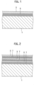
- an engine compressor vane or blade is comprised of a base body 1 of the compressor vane or blade and a coating 3 covering the base body 1.
- the base body 1 is one of vanes and blades of a compressor for an aircraft jet engine or a gas turbine engine and is applicable to either a rotor blade or a stator vane.
- the coating 3 is of a titanium-silicon nitride (Ti x Si 1-x N) for example.
- the coating thickness may be arbitrarily determined but may be 3 micrometers or more for example as a greater thickness is advantageous in order to ensure a longer lifetime. Further, it may be 10 micrometers or less for example as a smaller thickness is advantageous in order to reduce a risk for causing defects.
- Titanium and silicon contained in the coating 3 when coexisting with sulfates, form complex oxides at considerably elevated temperatures.
- a coating having such a property is referred to as "exfoliative coating”.
- Titanium could be substituted for zirconium or hafnium, both of which have equivalent chemical properties as described above.
- the coating 3 may include a zirconium-silicon nitride (Zr x Si 1-x N) or a hafniumsilicon nitride (Hf x Si 1-x N) .
- Vanadium or chemical equivalents such as niobium or tantalum, is available as the exfoliative coating as described earlier. More specifically, the coating 3 may be of any nitrides of one or more metals selected from the group of vanadium, niobium and tantalum.
- a smoother surface of the coating 3 is advantageous in light of prevention of adhesion of the deposits.
- the surface roughness of the coating 3 is preferably 0.1 Ra or less (Ra is an arithmetic average roughness based on Japanese Industrial Standards: JIS-B-0601-2001) .
- the intermediate coating 5 is formed of, or includes, any components distinct from the coating 3, or alternatively may be formed of the same components but have a distinct composition.
- the intermediate coating 5 may further include two or more layers that are distinguishable from each other.
- the components for the intermediate coating 5 may be arbitrarily selected in light of various properties.
- a titanium-aluminum nitride (Ti y Al 1-y N) or a chromium-aluminum nitride (Cr z Al 1-z N) is applicable to the coating 5 in light of improvement of corrosion-resistance and erosion-resistance for example.
- any substances that are advantageous for improving adhesion between the coating 3 and the base body 1 or relaxing stress around the interface can be selected and applied to the coating 5.
- the coating 3 and another coating 7 may be alternately layered to form a multi-layered coating of three or more sets of the alternate layers as shown in FIG. 2 .
- To form a multi-layered structure is advantageous for relaxing residual stress or such.
- a coating of a titanium-silicon nitride and a coating of a titanium-aluminum nitride may be alternately layered.
- a coating of a titanium-silicon nitride and a coating of a vanadium nitride may be alternately layered.
- both of them may be titanium-silicon nitrides but ratios of titanium to silicon therein may be differentiated.
- the other coating 7 by itself may include two or more layers mutually distinguishable.
- the uppermost layer is preferably the coating 3. In the multi-layered coating, each layer may be about from 10 to 20 nm in thickness.
- the coating 3 fully covers the airfoil faces of the engine compressor vane or blade at least, it may further cover its platform section (in a case of a rotor blade), or its inner band section and its outer band section (in a case of a stator vane). Further the coating 3 may be limited to these sections. Other sections in the engine compressor vane or blade are either a section used for fixation to the engine or a section to rub against another member. These sections will, if coated by any hard coating such as nitrides, will soon wear the opposite member off. To limit the coating on the airfoil faces and the platform section or the inner band section and the outer band section is advantageous for elongating the lifetime of the opposite member.
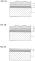
- Deposits 9 contain dust, sand, volcanic ash, moisture, sulfates, sulfites, chlorides, carbonates and such, and can adhere onto the coating 3 as shown in FIG. 3A .
- the combination of oxidative power by the sulfates or such and elevated temperatures about 400 - 700 degrees C for example created by adiabatic compression of the air causes formation of oxides 11 of the coating 3 at the interface between the coating 3 and the deposits 9 as shown in FIG. 3B .
- oxides 11 contain brittle substances such as titanium oxide or such, the deposits 9 along with the oxides 11 exfoliate therefrom. Observation of its cross section by TEM or such shows that only a layer of the oxides 11 several hundred nm in thickness at the most exists there. More specifically, it is considered that the oxides 11 would exfoliate before it grows up to several hundred nm in thickness.
- a fresh surface of the coating 3 is exposed as shown in FIG. 3C , and can create again the action of promoting exfoliation of deposits that are going to adhere onto the surface.
- Loss of the coating 3 in each occasion of exfoliation would be no more than several hundred nm in thickness as the layer of the oxides 11 could exfoliate before growing thick as described above.
- the thickness of the coating 3 is about 3 - 10 micrometers as also described above, the coating 3 survives even after repeating exfoliation several ten times and therefore keeps its effects for a long term.
- the coating 3 (or the coatings 5, 7 as well) on the base body 1 can be formed by using a known arc ion plating method for example. Alternatively, a sputtering method or any of other coating methods is also applicable. The production method will be described below, in which the arc ion plating method is applied.
- the base body 1 and a raw material for evaporation are introduced into an arc ion plating apparatus.
- the coating 3 is to be formed of a titanium-silicon nitride
- the raw material is an ingot of a titanium-silicon alloy. Its composition should be selected in accordance with a target composition as desired in the coating.
- the base body 1 is a rotor blade
- its dovetail section is fit into the holder to combine the base body with the holder. This is not only to establish electrical connection but also uses the holder to shelter the dovetail section from discharge, thereby being helpful to limit formation of the coating to a restricted portion. More specifically, this is helpful to limit formation of the coating to the airfoil faces and the platform section of the rotor blade.
- the base body 1 is a stator vane
- structures outside the outer band section or inside the inner band section are used. This is helpful to limit formation of the coating to the airfoil faces and the outer band section or the inner band section of the stator vane.
- the chamber is gas-tightly closed and evacuated down to a proper vacuum by means of a vacuum pump. This is helpful to eliminate impurities.
- the evacuation is continued to the extent that a degree of vacuum reaches about 0.01 Pa or such.
- valves of the gas supplier device are opened and thereby argon and nitrogen are introduced therein so as to regulate the pressure in the chamber.
- the pressure is 2 - 10 Pa for example.
- a discharge power source By a discharge power source, a voltage is applied between the evaporation source and the chamber to generate discharge therebetween, and, simultaneously by a bias power source, a bias voltage is applied to the base body 1.
- the titanium-silicon alloy as the evaporation source works as a cathode to generate the discharge. And as well, titanium and silicon change into vapor and are partly ionized and accelerated by the bias voltage toward the base body 1. They react with nitrogen in the gas phase to form the coating 3.
- sections sheltered in the holder are free from formation of the coating but gas phase particles are induced by the bias electric field to come around to all the exposed surfaces of the base body 1. Thereby the coating 3 fully covers all the surfaces other than the sheltered surfaces.
- burner rig tests are executed to compare adhesion amounts of deposits.
- a burner rig test apparatus is generally constituted of a burner 13 for generating hot gas and a holder 15 for supporting test pieces.
- a fuel nozzle 17 comprised of a supply system for supplying kerosene for example and a salt water nozzle 19 comprised of a salt water supply system are connected.
- a plug 21 As gas flow expelled from these nozzles is ignited by a plug 21, hot gas flow F is generated.
- the holder 15 is so constituted as to support a plurality of test pieces P of a round bar shape. By rotating the holder 15 around an axis perpendicular to the gas flow F by means of a motor 23, the plurality of test pieces P is unitarily exposed to the hot gas flow F.
- Test pieces of a round bar shape formed of INCONEL718 (INCONEL is a name commonly used by persons skilled in this art field) on which titanium-silicon nitride (TiSiN) coatings are formed, test pieces on which vanadium nitride (VN) coatings are formed, and test pieces without coatings are respectively produced.
- Table 1 summarizes relations between the compositions of the evaporation raw materials (target compositions) and the compositions in the formed coatings, in regard to the titanium-silicon nitride.
- the compositions of the coatings are results from elemental analyses by EPMA, each in which three spots in each SEM image are subject to point analysis and results are averaged.
- Table 1 Compositions of Coatings (at%) Evaporated Material (Target Composition) Composition of Coating (at%) Ti : Si Ti Si 85 : 15 87.8 12.2 75 : 25 78.5 21.5 60 : 40 61.9 38.1
- compositions of the coatings can be regulated in accordance with the compositions of the evaporation raw materials.
- the compositions of the coatings are not based on results of elemental analyses but on the compositions of the evaporation raw materials (target compositions).
- the coatings will often be expressed in the form such as Ti 0.75 Si 0.25 N so that the coatings are expressed in combination with these compositions.
- test pieces are respectively served for the burner rig test.
- salt water calcium sulfate solution is supplied to the burner.
- Each test piece is attached to the holder and is, with rotating the holder, exposed to hot gas flow for two hours, thereafter detached therefrom and subject to visual observation and weight change measurement. Thereafter each test piece is again attached to the holder and is, with rotating the holder, exposed to hot gas flow for forty hours, thereafter detached therefrom and subject to visual observation and weight change measurement.
- Table 2 summarizes the measurement results of weight changes.
- test pieces without the coatings exhibit ash gray deposits adhering on whole portions exposed to the hot gas flow. While the test pieces with the coatings also exhibit ash gray deposits, these deposits are partly exfoliated and portions from which the deposits come off exhibit metallic luster.
- the results of the weight change measurements present that the test pieces without the coatings make considerable weight gains, which are considered to be corresponding to the weights of the deposits, but the test pieces with the coatings only make slight weight gains. As being apparent from these test results, the test pieces with the coatings have a prominent effect of promoting exfoliation of the deposits as compared with those without the coatings.
- the multi-layered coatings exhibit similar effects.
- the multi-layered coating of the combination of titanium-silicon nitride and vanadium nitride is excellent in the effects.
- An engine compressor vane or blade is provided, on which deposits hardly deposit even in an environment containing abundant foreign substances.
Landscapes
- Engineering & Computer Science (AREA)
- Mechanical Engineering (AREA)
- General Engineering & Computer Science (AREA)
- Chemical & Material Sciences (AREA)
- Materials Engineering (AREA)
- Chemical Kinetics & Catalysis (AREA)
- Metallurgy (AREA)
- Organic Chemistry (AREA)
- Structures Of Non-Positive Displacement Pumps (AREA)
- Turbine Rotor Nozzle Sealing (AREA)
- Physical Vapour Deposition (AREA)
Claims (5)
- Verdichterleitschaufel oder -schaufel für ein Triebwerk, das in einer Umgebung verwendet wird, die reichlich Fremdkörper enthält, wobei die Verdichterleitschaufel oder -schaufel umfasst:einen Grundkörper (1) der Verdichterleitschaufel oder -schaufel; undeine Beschichtung (3), die den Grundkörper abdeckt,dadurch gekennzeichnet, dassdie Beschichtung (3) aus einem Titannitrid mit mehr als 60 at%, aber weniger als 85 at%, und einem Rest aus Silizium besteht.
- Verdichterleitschaufel oder -schaufel nach Anspruch 1, dadurch gekennzeichnet, dass:
die Beschichtung (3) auf eine Profilfläche, einen Plattformabschnitt oder einen inneren Bandabschnitt und einen äußeren Bandabschnitt begrenzt ist und diese bzw. diesen vollständig abdeckt. - Verdichterleitschaufel oder -schaufel nach Anspruch 1 oder 2, dadurch gekennzeichnet, dass sie ferner umfasst:
eine Zwischenbeschichtung (5), die zwischen der Beschichtung (3) und dem Grundkörper (1) angeordnet ist. - Verdichterleitschaufel oder -schaufel nach Anspruch 3, dadurch gekennzeichnet, dass:
die Beschichtung (3) und die Zwischenbeschichtung (5) abwechselnd geschichtet sind, um eine mehrschichtige Beschichtung aus drei Sätzen oder mehr Schichten zu bilden. - Verdichterleitschaufel oder -schaufel nach Anspruch 3, dadurch gekennzeichnet, dass:
die Zwischenbeschichtung (5) aus einem oder mehreren besteht, die ausgewählt sind aus der Gruppe von Titan-Aluminium-Nitrid und Chrom-Aluminium-Nitrid.
Applications Claiming Priority (2)
| Application Number | Priority Date | Filing Date | Title |
|---|---|---|---|
| JP2014262590 | 2014-12-25 | ||
| PCT/JP2015/085299 WO2016104303A1 (ja) | 2014-12-25 | 2015-12-17 | エンジン用圧縮機翼 |
Publications (3)
| Publication Number | Publication Date |
|---|---|
| EP3199821A1 EP3199821A1 (de) | 2017-08-02 |
| EP3199821A4 EP3199821A4 (de) | 2018-06-06 |
| EP3199821B1 true EP3199821B1 (de) | 2023-08-30 |
Family
ID=56150324
Family Applications (1)
| Application Number | Title | Priority Date | Filing Date |
|---|---|---|---|
| EP15872872.5A Active EP3199821B1 (de) | 2014-12-25 | 2015-12-17 | Verdichterschaufel für motor |
Country Status (5)
| Country | Link |
|---|---|
| US (1) | US10619644B2 (de) |
| EP (1) | EP3199821B1 (de) |
| JP (1) | JP6408607B2 (de) |
| CA (1) | CA2965607C (de) |
| WO (1) | WO2016104303A1 (de) |
Families Citing this family (1)
| Publication number | Priority date | Publication date | Assignee | Title |
|---|---|---|---|---|
| GB201802468D0 (en) * | 2018-02-15 | 2018-04-04 | Rolls Royce Plc | Coated substrate |
Family Cites Families (22)
| Publication number | Priority date | Publication date | Assignee | Title |
|---|---|---|---|---|
| US3850869A (en) | 1973-01-02 | 1974-11-26 | Johns Manville | Glass fiber sizing composition and resultant product with high resistance to abrasion |
| JPS6056061A (ja) * | 1983-09-07 | 1985-04-01 | Toshiba Corp | 耐摩耗部品 |
| US4904542A (en) * | 1988-10-11 | 1990-02-27 | Midwest Research Technologies, Inc. | Multi-layer wear resistant coatings |
| US5851678A (en) * | 1995-04-06 | 1998-12-22 | General Electric Company | Composite thermal barrier coating with impermeable coating |
| DE102004001392A1 (de) * | 2004-01-09 | 2005-08-04 | Mtu Aero Engines Gmbh | Verschleißschutzbeschichtung und Bauteil mit einer Verschleißschutzbeschichtung |
| US20050255329A1 (en) * | 2004-05-12 | 2005-11-17 | General Electric Company | Superalloy article having corrosion resistant coating thereon |
| US20060154093A1 (en) * | 2005-01-13 | 2006-07-13 | General Electric Company | Multilayered environmental barrier coating and related articles and methods |
| JP4764868B2 (ja) | 2007-12-07 | 2011-09-07 | トーカロ株式会社 | 圧縮機翼及び火力発電用ガスタービン |
| US20100247321A1 (en) * | 2008-01-08 | 2010-09-30 | General Electric Company | Anti-fouling coatings and articles coated therewith |
| US8790789B2 (en) * | 2008-05-29 | 2014-07-29 | General Electric Company | Erosion and corrosion resistant coatings, methods and articles |
| US20100086397A1 (en) | 2008-10-03 | 2010-04-08 | General Electric Company | Surface Treatments for Turbine Components to Reduce Particle Accumulation During Use Thereof |
| US20100226783A1 (en) * | 2009-03-06 | 2010-09-09 | General Electric Company | Erosion and Corrosion Resistant Turbine Compressor Airfoil and Method of Making the Same |
| CN101851738A (zh) | 2009-03-31 | 2010-10-06 | 东莞瀚晶纳米材料有限公司 | 纳米复合钛硅氮化物刀具涂层及其制备方法 |
| US20110165433A1 (en) * | 2010-01-06 | 2011-07-07 | General Electric Company | Erosion and corrosion resistant coating system for compressor |
| US8409695B2 (en) | 2010-05-28 | 2013-04-02 | Kennametal Inc. | Multilayer nitride hard coatings |
| DE102010060152A1 (de) * | 2010-10-25 | 2012-04-26 | Max-Planck-Institut für Plasmaphysik | Verschleißschutzbeschichtung |
| US8871340B2 (en) * | 2010-10-28 | 2014-10-28 | Sumitomo Electric Hardmetal Corp. | Surface-coated sintered body |
| US8496992B2 (en) * | 2010-12-10 | 2013-07-30 | Southwest Research Institute | Methods of forming nanocomposites containing nanodiamond particles by vapor deposition |
| EP2722415B1 (de) | 2011-06-17 | 2020-07-29 | Kabushiki Kaisha Kobe Seiko Sho (Kobe Steel, Ltd.) | Mit einer hartbeschichtung beschichtetes element |
| EP2767616A1 (de) * | 2013-02-15 | 2014-08-20 | Alstom Technology Ltd | Turbomaschinenkomponente mit einem erosions- und korrosionsbeständigen Beschichtungssystem und Verfahren zur Herstellung solch einer Komponente |
| JP2014238014A (ja) * | 2013-06-06 | 2014-12-18 | 株式会社Ihi | 航空機用ジェットエンジンの圧縮機のブレード及びその表面処理方法 |
| EP3374539B1 (de) * | 2015-11-10 | 2022-08-03 | Oerlikon Surface Solutions AG, Pfäffikon | Turbinenabstandssteuerungsbeschichtungen und verfahren |
-
2015
- 2015-12-17 EP EP15872872.5A patent/EP3199821B1/de active Active
- 2015-12-17 CA CA2965607A patent/CA2965607C/en active Active
- 2015-12-17 WO PCT/JP2015/085299 patent/WO2016104303A1/ja not_active Ceased
- 2015-12-17 JP JP2016566161A patent/JP6408607B2/ja active Active
-
2017
- 2017-04-03 US US15/477,740 patent/US10619644B2/en active Active
Also Published As
| Publication number | Publication date |
|---|---|
| JPWO2016104303A1 (ja) | 2017-09-07 |
| JP6408607B2 (ja) | 2018-10-17 |
| CA2965607A1 (en) | 2016-06-30 |
| EP3199821A4 (de) | 2018-06-06 |
| EP3199821A1 (de) | 2017-08-02 |
| US10619644B2 (en) | 2020-04-14 |
| CA2965607C (en) | 2019-07-23 |
| WO2016104303A1 (ja) | 2016-06-30 |
| US20170204871A1 (en) | 2017-07-20 |
Similar Documents
| Publication | Publication Date | Title |
|---|---|---|
| EP1327704B1 (de) | Thermische Schutztschicht und Verfahren zur deren Herstellung | |
| US6042898A (en) | Method for applying improved durability thermal barrier coatings | |
| US8062759B2 (en) | Thermal barrier coating systems including a rare earth aluminate layer for improved resistance to CMAS infiltration and coated articles | |
| US6586115B2 (en) | Yttria-stabilized zirconia with reduced thermal conductivity | |
| US12196109B2 (en) | Reactive thermal barrier coating | |
| US20020110698A1 (en) | Thermal barrier coatings and electron-beam, physical vapor deposition for making same | |
| US20140377473A1 (en) | Thermal barrier coating systems and processes therefor | |
| US6287644B1 (en) | Continuously-graded bond coat and method of manufacture | |
| JP2014166949A (ja) | セラミック粉末及びそのための方法 | |
| JP2019507828A (ja) | 基材上に高温保護層を接合するための付着促進層、並びにそれの製造方法 | |
| US20150064430A1 (en) | Heat insulation layer system with corrosion and erosion protection | |
| US10533566B2 (en) | Compressor vane or blade for engine with exfoliating coating | |
| US6663983B1 (en) | Thermal barrier coating with improved strength and fracture toughness | |
| EP3199821B1 (de) | Verdichterschaufel für motor | |
| WO2010116568A1 (ja) | 遮熱コーティング用材料、遮熱コーティング、タービン部材及びガスタービン | |
| US20230139765A1 (en) | Reactive thermal barrier coating | |
| Braun et al. | Oxidation behaviour of TiAlYN/CrN and CrAlYN/CrN nanoscale multilayer coatings with Al2O3 topcoat deposited on γ-TiAl alloys | |
| WO2011076446A1 (en) | Thermal barrier coating having low thermal conductivity | |
| Lima et al. | A Comparison of Thermal Shock Behavior between APS and Low-Energy VLPPS ZrO2-7% Y2O3 Thermal Barrier Coatings |
Legal Events
| Date | Code | Title | Description |
|---|---|---|---|
| STAA | Information on the status of an ep patent application or granted ep patent |
Free format text: STATUS: THE INTERNATIONAL PUBLICATION HAS BEEN MADE |
|
| PUAI | Public reference made under article 153(3) epc to a published international application that has entered the european phase |
Free format text: ORIGINAL CODE: 0009012 |
|
| STAA | Information on the status of an ep patent application or granted ep patent |
Free format text: STATUS: REQUEST FOR EXAMINATION WAS MADE |
|
| 17P | Request for examination filed |
Effective date: 20170425 |
|
| AK | Designated contracting states |
Kind code of ref document: A1 Designated state(s): AL AT BE BG CH CY CZ DE DK EE ES FI FR GB GR HR HU IE IS IT LI LT LU LV MC MK MT NL NO PL PT RO RS SE SI SK SM TR |
|
| AX | Request for extension of the european patent |
Extension state: BA ME |
|
| DAV | Request for validation of the european patent (deleted) | ||
| DAX | Request for extension of the european patent (deleted) | ||
| A4 | Supplementary search report drawn up and despatched |
Effective date: 20180508 |
|
| RIC1 | Information provided on ipc code assigned before grant |
Ipc: F01D 5/28 20060101ALI20180502BHEP Ipc: C23C 14/06 20060101AFI20180502BHEP Ipc: F04D 29/32 20060101ALI20180502BHEP Ipc: F04D 29/02 20060101ALI20180502BHEP Ipc: F02C 7/00 20060101ALI20180502BHEP |
|
| STAA | Information on the status of an ep patent application or granted ep patent |
Free format text: STATUS: EXAMINATION IS IN PROGRESS |
|
| 17Q | First examination report despatched |
Effective date: 20210621 |
|
| GRAP | Despatch of communication of intention to grant a patent |
Free format text: ORIGINAL CODE: EPIDOSNIGR1 |
|
| STAA | Information on the status of an ep patent application or granted ep patent |
Free format text: STATUS: GRANT OF PATENT IS INTENDED |
|
| INTG | Intention to grant announced |
Effective date: 20230405 |
|
| GRAS | Grant fee paid |
Free format text: ORIGINAL CODE: EPIDOSNIGR3 |
|
| GRAA | (expected) grant |
Free format text: ORIGINAL CODE: 0009210 |
|
| STAA | Information on the status of an ep patent application or granted ep patent |
Free format text: STATUS: THE PATENT HAS BEEN GRANTED |
|
| RAP3 | Party data changed (applicant data changed or rights of an application transferred) |
Owner name: PROTERIAL, LTD. Owner name: IHI CORPORATION |
|
| AK | Designated contracting states |
Kind code of ref document: B1 Designated state(s): AL AT BE BG CH CY CZ DE DK EE ES FI FR GB GR HR HU IE IS IT LI LT LU LV MC MK MT NL NO PL PT RO RS SE SI SK SM TR |
|
| REG | Reference to a national code |
Ref country code: GB Ref legal event code: FG4D |
|
| REG | Reference to a national code |
Ref country code: CH Ref legal event code: EP |
|
| REG | Reference to a national code |
Ref country code: DE Ref legal event code: R096 Ref document number: 602015085470 Country of ref document: DE |
|
| REG | Reference to a national code |
Ref country code: IE Ref legal event code: FG4D |
|
| REG | Reference to a national code |
Ref country code: LT Ref legal event code: MG9D |
|
| REG | Reference to a national code |
Ref country code: NL Ref legal event code: MP Effective date: 20230830 |
|
| REG | Reference to a national code |
Ref country code: AT Ref legal event code: MK05 Ref document number: 1605545 Country of ref document: AT Kind code of ref document: T Effective date: 20230830 |
|
| PG25 | Lapsed in a contracting state [announced via postgrant information from national office to epo] |
Ref country code: GR Free format text: LAPSE BECAUSE OF FAILURE TO SUBMIT A TRANSLATION OF THE DESCRIPTION OR TO PAY THE FEE WITHIN THE PRESCRIBED TIME-LIMIT Effective date: 20231201 |
|
| PG25 | Lapsed in a contracting state [announced via postgrant information from national office to epo] |
Ref country code: IS Free format text: LAPSE BECAUSE OF FAILURE TO SUBMIT A TRANSLATION OF THE DESCRIPTION OR TO PAY THE FEE WITHIN THE PRESCRIBED TIME-LIMIT Effective date: 20231230 |
|
| PG25 | Lapsed in a contracting state [announced via postgrant information from national office to epo] |
Ref country code: SE Free format text: LAPSE BECAUSE OF FAILURE TO SUBMIT A TRANSLATION OF THE DESCRIPTION OR TO PAY THE FEE WITHIN THE PRESCRIBED TIME-LIMIT Effective date: 20230830 Ref country code: RS Free format text: LAPSE BECAUSE OF FAILURE TO SUBMIT A TRANSLATION OF THE DESCRIPTION OR TO PAY THE FEE WITHIN THE PRESCRIBED TIME-LIMIT Effective date: 20230830 Ref country code: NO Free format text: LAPSE BECAUSE OF FAILURE TO SUBMIT A TRANSLATION OF THE DESCRIPTION OR TO PAY THE FEE WITHIN THE PRESCRIBED TIME-LIMIT Effective date: 20231130 Ref country code: LV Free format text: LAPSE BECAUSE OF FAILURE TO SUBMIT A TRANSLATION OF THE DESCRIPTION OR TO PAY THE FEE WITHIN THE PRESCRIBED TIME-LIMIT Effective date: 20230830 Ref country code: LT Free format text: LAPSE BECAUSE OF FAILURE TO SUBMIT A TRANSLATION OF THE DESCRIPTION OR TO PAY THE FEE WITHIN THE PRESCRIBED TIME-LIMIT Effective date: 20230830 Ref country code: IS Free format text: LAPSE BECAUSE OF FAILURE TO SUBMIT A TRANSLATION OF THE DESCRIPTION OR TO PAY THE FEE WITHIN THE PRESCRIBED TIME-LIMIT Effective date: 20231230 Ref country code: HR Free format text: LAPSE BECAUSE OF FAILURE TO SUBMIT A TRANSLATION OF THE DESCRIPTION OR TO PAY THE FEE WITHIN THE PRESCRIBED TIME-LIMIT Effective date: 20230830 Ref country code: GR Free format text: LAPSE BECAUSE OF FAILURE TO SUBMIT A TRANSLATION OF THE DESCRIPTION OR TO PAY THE FEE WITHIN THE PRESCRIBED TIME-LIMIT Effective date: 20231201 Ref country code: FI Free format text: LAPSE BECAUSE OF FAILURE TO SUBMIT A TRANSLATION OF THE DESCRIPTION OR TO PAY THE FEE WITHIN THE PRESCRIBED TIME-LIMIT Effective date: 20230830 Ref country code: AT Free format text: LAPSE BECAUSE OF FAILURE TO SUBMIT A TRANSLATION OF THE DESCRIPTION OR TO PAY THE FEE WITHIN THE PRESCRIBED TIME-LIMIT Effective date: 20230830 |
|
| PG25 | Lapsed in a contracting state [announced via postgrant information from national office to epo] |
Ref country code: PL Free format text: LAPSE BECAUSE OF FAILURE TO SUBMIT A TRANSLATION OF THE DESCRIPTION OR TO PAY THE FEE WITHIN THE PRESCRIBED TIME-LIMIT Effective date: 20230830 Ref country code: NL Free format text: LAPSE BECAUSE OF FAILURE TO SUBMIT A TRANSLATION OF THE DESCRIPTION OR TO PAY THE FEE WITHIN THE PRESCRIBED TIME-LIMIT Effective date: 20230830 |
|
| PG25 | Lapsed in a contracting state [announced via postgrant information from national office to epo] |
Ref country code: ES Free format text: LAPSE BECAUSE OF FAILURE TO SUBMIT A TRANSLATION OF THE DESCRIPTION OR TO PAY THE FEE WITHIN THE PRESCRIBED TIME-LIMIT Effective date: 20230830 |
|
| PG25 | Lapsed in a contracting state [announced via postgrant information from national office to epo] |
Ref country code: SM Free format text: LAPSE BECAUSE OF FAILURE TO SUBMIT A TRANSLATION OF THE DESCRIPTION OR TO PAY THE FEE WITHIN THE PRESCRIBED TIME-LIMIT Effective date: 20230830 Ref country code: RO Free format text: LAPSE BECAUSE OF FAILURE TO SUBMIT A TRANSLATION OF THE DESCRIPTION OR TO PAY THE FEE WITHIN THE PRESCRIBED TIME-LIMIT Effective date: 20230830 Ref country code: ES Free format text: LAPSE BECAUSE OF FAILURE TO SUBMIT A TRANSLATION OF THE DESCRIPTION OR TO PAY THE FEE WITHIN THE PRESCRIBED TIME-LIMIT Effective date: 20230830 Ref country code: EE Free format text: LAPSE BECAUSE OF FAILURE TO SUBMIT A TRANSLATION OF THE DESCRIPTION OR TO PAY THE FEE WITHIN THE PRESCRIBED TIME-LIMIT Effective date: 20230830 Ref country code: DK Free format text: LAPSE BECAUSE OF FAILURE TO SUBMIT A TRANSLATION OF THE DESCRIPTION OR TO PAY THE FEE WITHIN THE PRESCRIBED TIME-LIMIT Effective date: 20230830 Ref country code: CZ Free format text: LAPSE BECAUSE OF FAILURE TO SUBMIT A TRANSLATION OF THE DESCRIPTION OR TO PAY THE FEE WITHIN THE PRESCRIBED TIME-LIMIT Effective date: 20230830 Ref country code: PT Free format text: LAPSE BECAUSE OF FAILURE TO SUBMIT A TRANSLATION OF THE DESCRIPTION OR TO PAY THE FEE WITHIN THE PRESCRIBED TIME-LIMIT Effective date: 20240102 Ref country code: SK Free format text: LAPSE BECAUSE OF FAILURE TO SUBMIT A TRANSLATION OF THE DESCRIPTION OR TO PAY THE FEE WITHIN THE PRESCRIBED TIME-LIMIT Effective date: 20230830 |
|
| PG25 | Lapsed in a contracting state [announced via postgrant information from national office to epo] |
Ref country code: IT Free format text: LAPSE BECAUSE OF FAILURE TO SUBMIT A TRANSLATION OF THE DESCRIPTION OR TO PAY THE FEE WITHIN THE PRESCRIBED TIME-LIMIT Effective date: 20230830 |
|
| REG | Reference to a national code |
Ref country code: DE Ref legal event code: R097 Ref document number: 602015085470 Country of ref document: DE |
|
| PLBE | No opposition filed within time limit |
Free format text: ORIGINAL CODE: 0009261 |
|
| STAA | Information on the status of an ep patent application or granted ep patent |
Free format text: STATUS: NO OPPOSITION FILED WITHIN TIME LIMIT |
|
| PG25 | Lapsed in a contracting state [announced via postgrant information from national office to epo] |
Ref country code: SI Free format text: LAPSE BECAUSE OF FAILURE TO SUBMIT A TRANSLATION OF THE DESCRIPTION OR TO PAY THE FEE WITHIN THE PRESCRIBED TIME-LIMIT Effective date: 20230830 |
|
| REG | Reference to a national code |
Ref country code: CH Ref legal event code: PL |
|
| 26N | No opposition filed |
Effective date: 20240603 |
|
| PG25 | Lapsed in a contracting state [announced via postgrant information from national office to epo] |
Ref country code: LU Free format text: LAPSE BECAUSE OF NON-PAYMENT OF DUE FEES Effective date: 20231217 |
|
| PG25 | Lapsed in a contracting state [announced via postgrant information from national office to epo] |
Ref country code: MC Free format text: LAPSE BECAUSE OF FAILURE TO SUBMIT A TRANSLATION OF THE DESCRIPTION OR TO PAY THE FEE WITHIN THE PRESCRIBED TIME-LIMIT Effective date: 20230830 |
|
| GBPC | Gb: european patent ceased through non-payment of renewal fee |
Effective date: 20231217 |
|
| REG | Reference to a national code |
Ref country code: BE Ref legal event code: MM Effective date: 20231231 |
|
| PG25 | Lapsed in a contracting state [announced via postgrant information from national office to epo] |
Ref country code: MC Free format text: LAPSE BECAUSE OF FAILURE TO SUBMIT A TRANSLATION OF THE DESCRIPTION OR TO PAY THE FEE WITHIN THE PRESCRIBED TIME-LIMIT Effective date: 20230830 Ref country code: LU Free format text: LAPSE BECAUSE OF NON-PAYMENT OF DUE FEES Effective date: 20231217 |
|
| REG | Reference to a national code |
Ref country code: IE Ref legal event code: MM4A |
|
| PG25 | Lapsed in a contracting state [announced via postgrant information from national office to epo] |
Ref country code: IE Free format text: LAPSE BECAUSE OF NON-PAYMENT OF DUE FEES Effective date: 20231217 |
|
| PG25 | Lapsed in a contracting state [announced via postgrant information from national office to epo] |
Ref country code: GB Free format text: LAPSE BECAUSE OF NON-PAYMENT OF DUE FEES Effective date: 20231217 |
|
| PG25 | Lapsed in a contracting state [announced via postgrant information from national office to epo] |
Ref country code: BE Free format text: LAPSE BECAUSE OF NON-PAYMENT OF DUE FEES Effective date: 20231231 |
|
| PG25 | Lapsed in a contracting state [announced via postgrant information from national office to epo] |
Ref country code: FR Free format text: LAPSE BECAUSE OF NON-PAYMENT OF DUE FEES Effective date: 20231231 |
|
| PG25 | Lapsed in a contracting state [announced via postgrant information from national office to epo] |
Ref country code: CH Free format text: LAPSE BECAUSE OF NON-PAYMENT OF DUE FEES Effective date: 20231231 |
|
| PG25 | Lapsed in a contracting state [announced via postgrant information from national office to epo] |
Ref country code: IE Free format text: LAPSE BECAUSE OF NON-PAYMENT OF DUE FEES Effective date: 20231217 Ref country code: GB Free format text: LAPSE BECAUSE OF NON-PAYMENT OF DUE FEES Effective date: 20231217 Ref country code: FR Free format text: LAPSE BECAUSE OF NON-PAYMENT OF DUE FEES Effective date: 20231231 Ref country code: CH Free format text: LAPSE BECAUSE OF NON-PAYMENT OF DUE FEES Effective date: 20231231 Ref country code: BE Free format text: LAPSE BECAUSE OF NON-PAYMENT OF DUE FEES Effective date: 20231231 |
|
| PG25 | Lapsed in a contracting state [announced via postgrant information from national office to epo] |
Ref country code: BG Free format text: LAPSE BECAUSE OF FAILURE TO SUBMIT A TRANSLATION OF THE DESCRIPTION OR TO PAY THE FEE WITHIN THE PRESCRIBED TIME-LIMIT Effective date: 20230830 |
|
| PG25 | Lapsed in a contracting state [announced via postgrant information from national office to epo] |
Ref country code: BG Free format text: LAPSE BECAUSE OF FAILURE TO SUBMIT A TRANSLATION OF THE DESCRIPTION OR TO PAY THE FEE WITHIN THE PRESCRIBED TIME-LIMIT Effective date: 20230830 |
|
| PGFP | Annual fee paid to national office [announced via postgrant information from national office to epo] |
Ref country code: DE Payment date: 20241231 Year of fee payment: 10 |
|
| PG25 | Lapsed in a contracting state [announced via postgrant information from national office to epo] |
Ref country code: CY Free format text: LAPSE BECAUSE OF FAILURE TO SUBMIT A TRANSLATION OF THE DESCRIPTION OR TO PAY THE FEE WITHIN THE PRESCRIBED TIME-LIMIT; INVALID AB INITIO Effective date: 20151217 |
|
| PG25 | Lapsed in a contracting state [announced via postgrant information from national office to epo] |
Ref country code: HU Free format text: LAPSE BECAUSE OF FAILURE TO SUBMIT A TRANSLATION OF THE DESCRIPTION OR TO PAY THE FEE WITHIN THE PRESCRIBED TIME-LIMIT; INVALID AB INITIO Effective date: 20151217 |
|
| PG25 | Lapsed in a contracting state [announced via postgrant information from national office to epo] |
Ref country code: TR Free format text: LAPSE BECAUSE OF FAILURE TO SUBMIT A TRANSLATION OF THE DESCRIPTION OR TO PAY THE FEE WITHIN THE PRESCRIBED TIME-LIMIT Effective date: 20230830 |