EP3199754B1 - Inlet guide assembly - Google Patents
Inlet guide assembly Download PDFInfo
- Publication number
- EP3199754B1 EP3199754B1 EP17153698.0A EP17153698A EP3199754B1 EP 3199754 B1 EP3199754 B1 EP 3199754B1 EP 17153698 A EP17153698 A EP 17153698A EP 3199754 B1 EP3199754 B1 EP 3199754B1
- Authority
- EP
- European Patent Office
- Prior art keywords
- nozzles
- flow
- turbine
- nozzle
- inlet guide
- Prior art date
- Legal status (The legal status is an assumption and is not a legal conclusion. Google has not performed a legal analysis and makes no representation as to the accuracy of the status listed.)
- Active
Links
- 238000002485 combustion reaction Methods 0.000 claims description 26
- 150000001875 compounds Chemical class 0.000 claims description 14
- 238000011144 upstream manufacturing Methods 0.000 claims description 13
- 238000004891 communication Methods 0.000 claims description 10
- 239000012530 fluid Substances 0.000 claims description 6
- 238000000034 method Methods 0.000 claims description 5
- 238000006243 chemical reaction Methods 0.000 description 24
- 239000000446 fuel Substances 0.000 description 8
- 230000002093 peripheral effect Effects 0.000 description 7
- 230000000712 assembly Effects 0.000 description 4
- 238000000429 assembly Methods 0.000 description 4
- 239000007789 gas Substances 0.000 description 4
- 230000001133 acceleration Effects 0.000 description 3
- 230000006835 compression Effects 0.000 description 3
- 238000007906 compression Methods 0.000 description 3
- 239000002826 coolant Substances 0.000 description 3
- 239000000203 mixture Substances 0.000 description 3
- 238000004880 explosion Methods 0.000 description 2
- 238000012986 modification Methods 0.000 description 2
- 230000004048 modification Effects 0.000 description 2
- 230000003068 static effect Effects 0.000 description 2
- 239000002551 biofuel Substances 0.000 description 1
- 230000005540 biological transmission Effects 0.000 description 1
- 230000000295 complement effect Effects 0.000 description 1
- 238000001816 cooling Methods 0.000 description 1
- 230000001419 dependent effect Effects 0.000 description 1
- -1 diesel Substances 0.000 description 1
- 238000007599 discharging Methods 0.000 description 1
- KVIPHDKUOLVVQN-UHFFFAOYSA-N ethene;hydrate Chemical group O.C=C KVIPHDKUOLVVQN-UHFFFAOYSA-N 0.000 description 1
- 238000002347 injection Methods 0.000 description 1
- 239000007924 injection Substances 0.000 description 1
- 239000003350 kerosene Substances 0.000 description 1
- 239000000463 material Substances 0.000 description 1
- 238000005192 partition Methods 0.000 description 1
- 230000000750 progressive effect Effects 0.000 description 1
- 230000001902 propagating effect Effects 0.000 description 1
- 238000011084 recovery Methods 0.000 description 1
- 238000007789 sealing Methods 0.000 description 1
- 239000007787 solid Substances 0.000 description 1
- 230000000087 stabilizing effect Effects 0.000 description 1
Images


Classifications
-
- F—MECHANICAL ENGINEERING; LIGHTING; HEATING; WEAPONS; BLASTING
- F01—MACHINES OR ENGINES IN GENERAL; ENGINE PLANTS IN GENERAL; STEAM ENGINES
- F01D—NON-POSITIVE DISPLACEMENT MACHINES OR ENGINES, e.g. STEAM TURBINES
- F01D9/00—Stators
- F01D9/02—Nozzles; Nozzle boxes; Stator blades; Guide conduits, e.g. individual nozzles
- F01D9/04—Nozzles; Nozzle boxes; Stator blades; Guide conduits, e.g. individual nozzles forming ring or sector
- F01D9/041—Nozzles; Nozzle boxes; Stator blades; Guide conduits, e.g. individual nozzles forming ring or sector using blades
-
- F—MECHANICAL ENGINEERING; LIGHTING; HEATING; WEAPONS; BLASTING
- F01—MACHINES OR ENGINES IN GENERAL; ENGINE PLANTS IN GENERAL; STEAM ENGINES
- F01D—NON-POSITIVE DISPLACEMENT MACHINES OR ENGINES, e.g. STEAM TURBINES
- F01D1/00—Non-positive-displacement machines or engines, e.g. steam turbines
- F01D1/02—Non-positive-displacement machines or engines, e.g. steam turbines with stationary working-fluid guiding means and bladed or like rotor, e.g. multi-bladed impulse steam turbines
- F01D1/026—Impact turbines with buckets, i.e. impulse turbines, e.g. Pelton turbines
-
- F—MECHANICAL ENGINEERING; LIGHTING; HEATING; WEAPONS; BLASTING
- F01—MACHINES OR ENGINES IN GENERAL; ENGINE PLANTS IN GENERAL; STEAM ENGINES
- F01D—NON-POSITIVE DISPLACEMENT MACHINES OR ENGINES, e.g. STEAM TURBINES
- F01D5/00—Blades; Blade-carrying members; Heating, heat-insulating, cooling or antivibration means on the blades or the members
- F01D5/02—Blade-carrying members, e.g. rotors
-
- F—MECHANICAL ENGINEERING; LIGHTING; HEATING; WEAPONS; BLASTING
- F01—MACHINES OR ENGINES IN GENERAL; ENGINE PLANTS IN GENERAL; STEAM ENGINES
- F01D—NON-POSITIVE DISPLACEMENT MACHINES OR ENGINES, e.g. STEAM TURBINES
- F01D5/00—Blades; Blade-carrying members; Heating, heat-insulating, cooling or antivibration means on the blades or the members
- F01D5/12—Blades
-
- F—MECHANICAL ENGINEERING; LIGHTING; HEATING; WEAPONS; BLASTING
- F02—COMBUSTION ENGINES; HOT-GAS OR COMBUSTION-PRODUCT ENGINE PLANTS
- F02B—INTERNAL-COMBUSTION PISTON ENGINES; COMBUSTION ENGINES IN GENERAL
- F02B37/00—Engines characterised by provision of pumps driven at least for part of the time by exhaust
-
- F—MECHANICAL ENGINEERING; LIGHTING; HEATING; WEAPONS; BLASTING
- F02—COMBUSTION ENGINES; HOT-GAS OR COMBUSTION-PRODUCT ENGINE PLANTS
- F02B—INTERNAL-COMBUSTION PISTON ENGINES; COMBUSTION ENGINES IN GENERAL
- F02B53/00—Internal-combustion aspects of rotary-piston or oscillating-piston engines
- F02B53/04—Charge admission or combustion-gas discharge
- F02B53/08—Charging, e.g. by means of rotary-piston pump
-
- F—MECHANICAL ENGINEERING; LIGHTING; HEATING; WEAPONS; BLASTING
- F01—MACHINES OR ENGINES IN GENERAL; ENGINE PLANTS IN GENERAL; STEAM ENGINES
- F01D—NON-POSITIVE DISPLACEMENT MACHINES OR ENGINES, e.g. STEAM TURBINES
- F01D17/00—Regulating or controlling by varying flow
- F01D17/10—Final actuators
- F01D17/12—Final actuators arranged in stator parts
-
- F—MECHANICAL ENGINEERING; LIGHTING; HEATING; WEAPONS; BLASTING
- F02—COMBUSTION ENGINES; HOT-GAS OR COMBUSTION-PRODUCT ENGINE PLANTS
- F02B—INTERNAL-COMBUSTION PISTON ENGINES; COMBUSTION ENGINES IN GENERAL
- F02B53/00—Internal-combustion aspects of rotary-piston or oscillating-piston engines
- F02B2053/005—Wankel engines
-
- F—MECHANICAL ENGINEERING; LIGHTING; HEATING; WEAPONS; BLASTING
- F05—INDEXING SCHEMES RELATING TO ENGINES OR PUMPS IN VARIOUS SUBCLASSES OF CLASSES F01-F04
- F05D—INDEXING SCHEME FOR ASPECTS RELATING TO NON-POSITIVE-DISPLACEMENT MACHINES OR ENGINES, GAS-TURBINES OR JET-PROPULSION PLANTS
- F05D2220/00—Application
- F05D2220/40—Application in turbochargers
-
- F—MECHANICAL ENGINEERING; LIGHTING; HEATING; WEAPONS; BLASTING
- F05—INDEXING SCHEMES RELATING TO ENGINES OR PUMPS IN VARIOUS SUBCLASSES OF CLASSES F01-F04
- F05D—INDEXING SCHEME FOR ASPECTS RELATING TO NON-POSITIVE-DISPLACEMENT MACHINES OR ENGINES, GAS-TURBINES OR JET-PROPULSION PLANTS
- F05D2260/00—Function
- F05D2260/96—Preventing, counteracting or reducing vibration or noise
- F05D2260/961—Preventing, counteracting or reducing vibration or noise by mistuning rotor blades or stator vanes with irregular interblade spacing, airfoil shape
-
- Y—GENERAL TAGGING OF NEW TECHNOLOGICAL DEVELOPMENTS; GENERAL TAGGING OF CROSS-SECTIONAL TECHNOLOGIES SPANNING OVER SEVERAL SECTIONS OF THE IPC; TECHNICAL SUBJECTS COVERED BY FORMER USPC CROSS-REFERENCE ART COLLECTIONS [XRACs] AND DIGESTS
- Y02—TECHNOLOGIES OR APPLICATIONS FOR MITIGATION OR ADAPTATION AGAINST CLIMATE CHANGE
- Y02T—CLIMATE CHANGE MITIGATION TECHNOLOGIES RELATED TO TRANSPORTATION
- Y02T10/00—Road transport of goods or passengers
- Y02T10/10—Internal combustion engine [ICE] based vehicles
- Y02T10/12—Improving ICE efficiencies
Definitions
- the application relates generally to compound engine assemblies and, more particularly, to turbine inlet guide assemblies for such engines.
- Compound engine assemblies including an impulse turbine with a reciprocating engine core are known and typically include exhaust pipes defining a nozzle at their end for communication with a flow path of the impulse turbine.
- US-2009/0136338 discloses an inlet guide assembly for a turbine receiving a pulsed flow whereby the guide vanes (nozzles) are firmly arranged on the guide vane support and exhibit different angle positions opposite to the rotor disk in different sectors of the peripheral region.
- each nozzle delivers the exhaust over a respective arc of the flow path, and flow velocity tends to drop along the respective arc, which may lead to inefficient use of the exhaust pulse energy within the turbine.
- an inlet guide assembly for a turbine receiving a pulsed flow
- the inlet guide assembly comprising a duct having an internal volume and an inlet port and a plurality of nozzles communicating with the internal volume, the inlet port configured to receive the pulsed flow, the plurality of nozzles each defining a respective nozzle area communicating between the internal volume and a flow path of the turbine, the nozzles arranged serially and spaced-apart along a direction of flow through the duct, at least one of the nozzles having a greater nozzle area than at least another one of the nozzles located upstream therefrom.
- a method of introducing a pulsed flow into a flow path of a turbine comprising: providing a plurality of circumferentially spaced nozzles in communication with the flow path of the turbine, the nozzles defining a greater restriction to the pulsed flow in a first location than in a second location along a circumferential direction of the nozzles; and directing the pulsed flow along a circumferential path to the first location and then to the second location so that the first location is upstream of the second location, while circulating the flow through the plurality of circumferentially spaced nozzles to the flow path of the turbine.
- the compound engine assembly 10 includes an engine core with one or more intermittent combustion internal combustion engine(s) 12.
- the internal combustion engine(s) 12 drive a common load.
- the common load includes an output shaft 14 which may be for example connected to a propeller through a reduction gearbox (not shown) and to which each internal engine is engaged.
- Other possible common loads may include, but are not limited to, one or more compressor and/or fan rotor(s), electrical generator(s), accessories, rotor mast(s), or any other type of load or combination thereof.
- the compound engine assembly 10 also includes a turbocharger 16, including a compressor 18 and a second stage turbine 20 which are drivingly interconnected by a shaft 22.
- the compressor 18 and the second stage turbine 20 may each be a single-stage device or a multiple-stage device with a single shaft or split on multiple independent shafts in parallel or in series, and may each be a centrifugal or axial device.
- the compressor 18 of the turbocharger 16 compresses the air before it enters the core engine(s) 12.
- the compressor 18 and the second stage turbine 20 may each include one or more rotors, with radial, axial or mixed flow blades.
- the shaft 22 of the turbocharger 16 extends along a different axis than that of the output shaft 14, for example parallel thereto; alternately, the shaft 22 of the turbocharger may extend transverse to the output shaft 14, or may be defined coaxially with the output shaft 14.
- the turbocharger shaft 22 and output shaft 14 are in driving engagement with one another, through any suitable type of transmission or gearbox 26, for example a planetary, star, offset or angular gear system.
- turbocharger 16 may be omitted.
- Each internal combustion engine 12 provides an exhaust flow in the form of exhaust pulses or pulsed flow, caused by the intermittent combustion occurring with the intermittent combustion internal combustion engine 12.
- the exhaust flow of the internal combustion engine 12 is supplied to a compound or first stage turbine 24 in fluid communication therewith.
- the first stage turbine 24 could be an axial, radial or mixed flow turbine.
- the first stage turbine 24 is drivingly interconnected to the second stage turbine 20 by being mounted to the same turbine shaft 22, and accordingly also drivingly engaged to the output shaft 14 through the gearbox 26.
- the turbines 24, 20 may rotate independently, with the first stage turbine 24 drivingly engaged to the output shaft 14, for example via the gearbox 26, and the second stage turbine 26 drivingly engaged to the compressor 18, for example via the turbine shaft 22.
- the outlet of the first stage turbine 24 is in fluid communication with an inlet of the second stage turbine 20. Energy is extracted from the exhaust gas exiting the first stage turbine 24 by the second stage turbine 20 to drive the compressor 18 via the connecting shaft 22.
- the second stage turbine 20 is a pressure turbine, also known as a reaction turbine
- the first stage turbine 24 is configured as a velocity type turbine, also known as an impulse turbine.
- a pure impulse turbine works by changing the direction of the flow without accelerating the flow inside the rotor; the fluid is deflected without a significant pressure drop across the rotor blades.
- the blades of the pure impulse turbine are designed such that in a transverse plane perpendicular to the direction of flow, the area defined between the blades is the same at the leading edges of the blades and at the trailing edges of the blade: the flow area of the turbine is constant, and the blades are usually symmetrical about the plane of the rotating disc.
- the work of the pure impulse turbine is due only to the change of direction in the flow through the turbine blades.
- Typical pure impulse turbines include steam and hydraulic turbines.
- a reaction turbine accelerates the flow inside the rotor but needs a static pressure drop across the rotor to enable this flow acceleration.
- the blades of the reaction turbine are designed such that in a transverse plane perpendicular to the direction of flow, the area defined between the blades is larger at the leading edges of the blades than at the trailing edges of the blade: the flow area of the turbine reduces along the direction of flow, and the blades are usually not symmetrical about the plane of the rotating disc.
- the work of the pure reaction turbine is due to the acceleration and turning of the flow through the turbine blades.
- Aeronautical turbines referred to as impulse turbines typically have a reaction ratio of 0.25 (25% reaction) or lower, although other values are also possible.
- the first stage turbine 24 is configured to take benefit of the kinetic energy of the pulsating flow exiting the internal combustion engine(s) 12 while stabilizing the flow, and the second stage turbine 20 is configured to extract energy from the remaining pressure in the flow. Accordingly, the first stage turbine 24 has a lower (i.e. lower value) reaction ratio than that of the second stage turbine 20.
- the second stage turbine 20 has a reaction ratio higher than 0.25; in another particular embodiment, the second stage turbine 20 has a reaction ratio higher than 0.3; in another particular embodiment, the second stage turbine 20 has a reaction ratio of about 0.5; in another particular embodiment, the second stage turbine 20 has a reaction ratio higher than 0.5.
- the first stage turbine 24 has a reaction ratio of at most 0.2; in another particular embodiment, the first stage turbine 24 has a reaction ratio of at most 0.15; in another particular embodiment, the first stage turbine 24 has a reaction ratio of at most 0.1; in another particular embodiment, the first stage turbine 24 has a reaction ratio of at most 0.05.
- reaction ratios for the second stage turbine 20 can be combined with any of the above-mentioned reaction ratios for the first stage turbine 24 and that these ratios can be pressure-based or temperature-based. Other values are also possible.
- the air may optionally circulate through an intercooler between the compressor 18 and the internal combustion engine(s) 12, and the engine assembly 10 also includes a cooling system, including for example a circulation system for a coolant (e.g. water-ethylene, oil, air) to cool the housing of each internal combustion engine 12, an oil coolant for the internal mechanical parts of the internal combustion engine(s) 12, one or more coolant heat exchangers, etc.
- a coolant e.g. water-ethylene, oil, air
- each internal combustion engine 12 which in a particular embodiment are common rail fuel injectors, communicate with a source 28 of Heavy fuel (e.g. diesel, kerosene (jet fuel), equivalent biofuel), and deliver the heavy fuel into the internal combustion engine(s) 12 such that the combustion chamber is stratified with a rich fuel-air mixture near the ignition source and a leaner mixture elsewhere.
- Heavy fuel e.g. diesel, kerosene (jet fuel), equivalent biofuel
- each internal combustion engine 12 is a rotary internal combustion engine having a rotor sealingly engaged in a respective housing.
- the rotary engine(s) is/are Wankel engine(s). Referring to Fig. 2 , an exemplary embodiment of a Wankel engine is shown; it is understood that the configuration of the internal combustion engine(s) 12 used in the compound engine assembly 10, e.g. placement of ports, number and placement of seals, etc., may vary from that of the embodiment shown.
- each internal combustion engine 12 may be of any other type including, but not limited to, any other type of rotary engine.
- each Wankel engine comprises a housing 32 defining an internal cavity with a profile defining two lobes, which is preferably an epitrochoid.
- a rotor 30 is received within the internal cavity.
- the rotor 30 defines three circumferentially-spaced apex portions 34, and a generally triangular profile with outwardly arched sides.
- the apex portions 34 are in sealing engagement with the inner surface of a peripheral wall 36 of the housing 32 to form three working chambers 38 between the rotor 30 and the housing 32.
- the rotor 30 is engaged to an eccentric portion 40 of the output shaft 14 to perform orbital revolutions within the internal cavity.
- the output shaft 14 performs three rotations for each orbital revolution of the rotor 30.
- the geometrical axis 42 of the rotor 30 is offset from and parallel to the axis 44 of the housing 32.
- each chamber 38 varies in volume and moves around the internal cavity to undergo the four phases of intake, compression, expansion and exhaust.
- An intake port 46 is provided through the peripheral wall 36 for successively admitting compressed air into each working chamber 38.
- An exhaust port 48 is also provided through the peripheral wall 36 for successively discharging the exhaust gases from each working chamber 38.
- Passages 50 for a glow plug, spark plug or other ignition element, as well as for one or more fuel injectors (not shown) are also provided through the peripheral wall 36.
- the intake port 46, the exhaust port 48 and/or the passages 50 may be provided through an end or side wall of the housing 32; and/or, the ignition element and a pilot fuel injector may communicate with a pilot subchamber (not shown) defined in the housing 32 and communicating with the internal cavity for providing a pilot injection.
- the pilot subchamber may be for example defined in an insert (not shown) received in the peripheral wall 36.
- the working chambers 38 are sealed, for example by spring-loaded apex seals 54 extending from the rotor 30 to engage the peripheral wall 36, and spring-loaded face or gas seals 56 and end or corner seals 58 extending from the rotor 30 to engage the end walls.
- the rotor 30 also includes at least one spring-loaded oil seal ring 60 biased against the end wall around the bearing for the rotor 30 on the shaft eccentric portion 40.
- Each Wankel engine provides an exhaust flow in the form of a relatively long exhaust pulse through the exhaust port 48; for example, in a particular embodiment, each Wankel engine has one explosion per 360° of rotation of the output shaft, with the exhaust port remaining open for about 270° of that rotation, thus providing for a pulse duty cycle of about 75%.
- a piston of a reciprocating 4-stroke piston engine typically has one explosion per 720° of rotation of the output shaft with the exhaust port remaining open for about 180° of that rotation, thus providing a pulse duty cycle of 25%.
- each Wankel engine has a volumetric expansion ratio of from 5 to 9, and a volumetric compression ratio lower than the volumetric expansion ratio.
- the power recovery of the first stage turbine 24 may be maximized by having the exhaust gas temperatures at the material limit, and as such is suitable for such relatively low volumetric compression ratios, which may help increase the power density of the Wankel engine and may also improve combustion at high speed and of heavy fuel.
- the compound engine assembly 10 includes two (2) internal combustion engines 12 in the form of Wankel engines, for example such as shown in Fig. 2 .
- more or less internal combustion engines may be provided; for example, in another particular embodiment, the engine core includes four (4) Wankel engines, or any suitable number of internal combustion engines having any other suitable configuration (e.g. reciprocating engine defining one exhaust port per piston).
- the first stage turbine 24 includes a circumferential array of rotor blades 62 adapted to rotate in an annular flow path 64.
- the turbine is an axial turbine, and the flow path 64 extends along an axial direction relative to an axis of rotation of the first stage turbine 24.
- the first stage turbine 24 may be a radial turbine, for example with an upstream part of the flow path extending along a radial direction.
- the compound engine assembly 10 includes an exhaust pipe 66 for each exhaust port 48.
- Each exhaust pipe 66 includes a first end 68 in fluid communication with the exhaust port 48 of the respective internal combustion engine 12 and an opposed second end 70 in fluid communication with an inlet guide assembly 72, 172, 272, 372, 372' of the first stage turbine 24, which communicates with the flow path 64 upstream of the rotor blades 62.
- the inlet guide assembly 72, 172, 272, 372, 372' thus receives the pulsed flow from the exhaust pipe(s) 66 and directs the pulsed flow into the flow path 64.
- a cross-sectional area of the exhaust pipe(s) 66 upstream of the second end 70 is constant, and this constant cross-sectional area corresponds to that of the engine exhaust port 48 connected to the exhaust pipe 66.
- the exhaust pipe 66 may have a different cross-sectional area than that of the exhaust port 48, and may be for example smaller than that of the corresponding exhaust port 48.
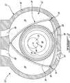
- the inlet guide assembly 72 includes an arcuately-shaped duct 74 defining one or more internal volume(s) 76.
- the duct 74 can be any structure adapted to receive and direct the pulsed flow therein along a circumferential direction 78.
- the duct 74 has axially spaced end faces 80 (only one end face is shown) interconnected by concentric radially spaced faces 82 for receiving and directing the pulsed flow within the duct 74.
- the duct 74 is an annular duct.
- the duct 74 may have a circular or semi-circular cross-section, such that some or all of the faces 80, 82 may be defined by a common wall.
- Each internal volume 76 is defined as a portion of the inner volume between the axially spaced end faces 80 and the radially spaced faces 82 of the duct 74.
- the duct 74 includes two interconnected internal volumes 76.
- Each of these two internal volumes 76 defines a section of the duct 74.
- each section expands over an arc covering an angle ⁇ approximately 120° of the circumference of the duct 74.
- the internal volumes 76 are separated from one another by any suitable type of partition 77, which may include a solid wall, spaced apart walls enclosing a cavity or other structure of the engine, or spaced apart, separate walls.
- the internal volumes 76 are shown as together extending around only part of a complete circumference, alternately the internal volumes 76 may together extend around a complete circumference of the duct 74 (e.g., two internal volumes extending around approximately 180° each as shown for example by the assembly 172 of Fig. 5 , three internal volumes extending around approximately 120° each). Moreover, the internal volumes 76 may together extend around only part of the circumference with different angular values than that shown (e.g. two or three internal volumes extending around approximately 90° each). Other values are of course possible.
- the duct 74 may be provided as a single structure or in separate sections each containing one of the internal volumes 76; such sections can abut one another and be interconnected, or be circumferentially spaced from one another when the internal volumes together extend around only part of a complete circumference.
- Each internal volume 76 includes an inlet port 84 configured to engage the second end 70 of the respective exhaust pipe 66 receiving the pulsed flow.
- the inlet port 84 fluidly communicates with the respective internal volume 76.
- each internal volume 76 includes circumferentially spaced outlet nozzles 86 arranged along an admission arc 75 and configured to communicate with the flow path 64 of the first stage turbine 24.
- the nozzles 86 also fluidly communicates with the respective internal volume 76 and are located upstream of the turbine blades 62.
- the inlet guide assembly 72 is configured for use with an axial turbine and accordingly the nozzles 86 are located on one of the end faces 80 to discharge the pulsed flow along an axial direction of the duct 74.
- the nozzles 86 are circumferentially distributed around the duct 74. Each nozzle 86 is located at a circumferential distance or arc length from the inlet port 84, measured along the circumferential direction 78 of the duct 74; the distance is thus defined along the arc extending between a centerline 90 of the inlet port 84 to a centerline 92 of each nozzle 86.
- Each nozzle 86 also defines a nozzle area 88 (open cross-sectional area) for providing the communication between the respective internal volume 76 and the turbine flow path 64.
- a nozzle 86' located at a distance R1 from the inlet port 84 has a nozzle area 88 which is smaller than that of a nozzle 86" located at a greater distance R2 from the inlet port 84.
- the nozzle 86' located closer to the inlet port 84 (upstream relative to the flow direction through the duct 74) has a smaller nozzle area 88. Therefore, the nozzles 86 define a greater restriction to the pulsed flow through the first nozzle 86' closer to the inlet port 84 compared to through the second nozzle 86" further away or downstream thereof.
- the pulsed flow circulating in the duct 74 is supersonic.
- An increase in nozzle area 88 as flow travels away from the inlet port 84 is thus desirable to increase the flow velocity of the pulsed flow since the pressure of the pulsed flow propagating through the duct 74 can be reduced over the arc of the internal volume 76 along the circumferential direction 78.
- the increase in nozzle area of the nozzles 86 located further away from the inlet port 84 allows for a greater increase in flow velocity through such nozzles 86 as compared to the nozzles closer to the inlet port 84, which in a particular embodiment allows to obtain a substantially constant flow velocity across the arc of the nozzles 86 within each internal volume 76.
- the nozzle area 88 of each nozzle 86 located at a given distance from the inlet port 84 is at least equal to that of the nozzle areas of the nozzles 86 located closer to the inlet port 84.
- the increase in the nozzle area 88 can be progressive or discrete as the distance R from the inlet port 84 increases. In the case of the discrete increase, adjacent nozzles 86 can have the same nozzle area 88.
- a first group of the nozzles 86 closer to the inlet port 84 can have a first nozzle area that is smaller than a second nozzle area of a second group of nozzles 86 further away from the inlet port 84.
- each nozzle 86 may have a greater nozzle area than that of the nozzles located closer to the inlet port 84.
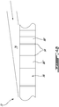
- each nozzle 86 is defined between adjacent pairs of circumferentially spaced vanes 94 spanning the open end face 80.
- the vanes 94 may have any appropriate type of airfoil profile.
- the nozzle area 88 of the nozzles 86 is varied by varying an inter-vane spacing or circumferential distance between the adjacent vanes.
- the inter-vane spacing or circumferential distance between the adjacent vanes 94 thus increases as the vanes 94 are located further away from the inlet port 84.
- the inter-vane spacing may progressively increase as the distance from the inlet port increases (as shown in Figs. 4A-4B ) or alternately, increase in groups (as shown in Fig. 5 ).
- a first group of nozzles may be defined by a first group of identically spaced vanes, and a second group of nozzles be defined by a second group of identically spaced vanes, with the vanes of the group closer to the inlet port 84 having a smaller inter-vane spacing.
- an inlet guide assembly 272 according to another particular embodiment is shown.
- the inlet guide assembly 272 of Fig. 6 is similar to the inlet guide assembly 72 of Fig. 4 , except that it is configured for use with a radial turbine; the end faces 80 are closed and the nozzles 286 span an inner one of the radially spaced faces 82 which is open, to discharge the pulsed flow along a radial direction of the duct 74.
- the nozzles 286 are also defined between adjacent vanes of a circumferential array of vanes 294. As in the embodiment of Fig. 4 , a smaller circumferential distance is defined between adjacent ones of the vanes 294 located closer to the inlet port 84 than that between adjacent ones of the vanes located further away from the inlet port 84.
- inlet guide assemblies 372, 372' suitable for use with an axial turbine.
- the nozzles 386, 386' are defined by spaced apart apertures 396 formed through one of the end faces 380 of the duct 374.
- the apertures 396 can have any suitable shape.
- the apertures 396 have an elliptical shape, slanted with respect to the flow.
- Each nozzle may be defined by a single aperture ( Fig. 7A ), or by a plurality of apertures with the nozzle area corresponding to the sum of the cross-sectional area of its apertures ( Fig. 7B for nozzles 386').
- the nozzles may be equally spaced apart along the direction of flow.
- the inlet guide assembly 72, 172, 272, 372, 372' is used for introducing the pulsed flow into a flow path 64 of the first stage turbine 24 by directing the pulsed flow into one or more internal volume(s) 76 of the duct 74 through the respective inlet of the duct 74, directing the pulsed flow circumferentially along each internal volume 76, and finally directing the pulsed flow from each internal volume 76 to the flow path 64 through the circumferentially spaced nozzles 86 of the duct 74.
Landscapes
- Engineering & Computer Science (AREA)
- Mechanical Engineering (AREA)
- General Engineering & Computer Science (AREA)
- Chemical & Material Sciences (AREA)
- Combustion & Propulsion (AREA)
- Turbine Rotor Nozzle Sealing (AREA)
- Supercharger (AREA)
Priority Applications (1)
| Application Number | Priority Date | Filing Date | Title |
|---|---|---|---|
| PL17153698T PL3199754T3 (pl) | 2016-01-29 | 2017-01-30 | Zespół kierownicy wlotowej |
Applications Claiming Priority (1)
| Application Number | Priority Date | Filing Date | Title |
|---|---|---|---|
| US15/010,634 US9890649B2 (en) | 2016-01-29 | 2016-01-29 | Inlet guide assembly |
Publications (2)
| Publication Number | Publication Date |
|---|---|
| EP3199754A1 EP3199754A1 (en) | 2017-08-02 |
| EP3199754B1 true EP3199754B1 (en) | 2019-03-13 |
Family
ID=57956119
Family Applications (1)
| Application Number | Title | Priority Date | Filing Date |
|---|---|---|---|
| EP17153698.0A Active EP3199754B1 (en) | 2016-01-29 | 2017-01-30 | Inlet guide assembly |
Country Status (7)
| Country | Link |
|---|---|
| US (1) | US9890649B2 (pl) |
| EP (1) | EP3199754B1 (pl) |
| CN (1) | CN108884759B (pl) |
| CA (1) | CA2956598C (pl) |
| ES (1) | ES2730203T3 (pl) |
| PL (1) | PL3199754T3 (pl) |
| WO (1) | WO2017127931A1 (pl) |
Families Citing this family (5)
| Publication number | Priority date | Publication date | Assignee | Title |
|---|---|---|---|---|
| CN111075513B (zh) * | 2019-11-12 | 2022-04-29 | 沈阳航空航天大学 | 一种扇形叶栅试验器及改变扇形叶栅进气角的方法 |
| CN111810242B (zh) * | 2020-08-05 | 2024-07-30 | 李海鹏 | 高压旋转活塞叶轮蒸汽动力机 |
| CN112478181A (zh) * | 2020-11-25 | 2021-03-12 | 中国航空工业集团公司沈阳飞机设计研究所 | 一种机载综合冷却系统 |
| CN116220843B (zh) * | 2023-02-27 | 2025-09-19 | 潍柴动力股份有限公司 | 一种双通道涡轮、涡轮增压器及发动机 |
| US12366176B2 (en) * | 2023-08-28 | 2025-07-22 | General Electric Company | Rotor system for a turbine engine |
Family Cites Families (19)
| Publication number | Priority date | Publication date | Assignee | Title |
|---|---|---|---|---|
| US856208A (en) | 1905-05-29 | 1907-06-11 | Backstrom Smith Steam Turbine & Mfg Company | Turbine nozzle-partition and nozzle. |
| US1069177A (en) | 1912-12-09 | 1913-08-05 | Connecticut Turbine Mfg Company | Elastic-fluid turbine. |
| GB226532A (en) | 1923-12-21 | 1925-03-12 | Vickers Electrical Co Ltd | An improved nozzle block for elastic fluid turbines |
| US1534721A (en) | 1924-04-28 | 1925-04-21 | Aeg | Construction of elastic-fluid turbines to prevent breakage of blades due to vibrations |
| US3006603A (en) | 1954-08-25 | 1961-10-31 | Gen Electric | Turbo-machine blade spacing with modulated pitch |
| US3873231A (en) * | 1972-08-11 | 1975-03-25 | Allis Chalmers | Centrifugal pump diffuser |
| JPS5525555A (en) * | 1978-08-12 | 1980-02-23 | Hitachi Ltd | Impeller |
| US6419464B1 (en) * | 2001-01-16 | 2002-07-16 | Honeywell International Inc. | Vane for variable nozzle turbocharger |
| US6457305B1 (en) * | 2001-02-07 | 2002-10-01 | James R. Schierbaum | Turbo shaft engine with acoustical compression flow amplifying ramjet |
| DE102005011482B4 (de) | 2005-03-12 | 2018-05-30 | Daimler Ag | Abgasturbolader mit einem Verdichter und einer Abgasturbine |
| EP2014925A1 (de) | 2007-07-12 | 2009-01-14 | ABB Turbo Systems AG | Diffuser für Radialverdichter |
| US7694518B2 (en) | 2007-08-14 | 2010-04-13 | Deere & Company | Internal combustion engine system having a power turbine with a broad efficiency range |
| DE102007056889A1 (de) | 2007-11-26 | 2009-05-28 | Bosch Mahle Turbo Systems Gmbh & Co. Kg | Abgasturbolader mit mindestens einer Turbine variabler Turbinengeometrie |
| CN102168610B (zh) * | 2010-02-26 | 2014-11-05 | 吴思 | 有间隔叶片室的非透平涡轮转子内燃机 |
| HRP20170078T1 (hr) | 2011-11-03 | 2017-03-10 | Duerr Cyplan Ltd. | Turbo stroj |
| WO2013153052A2 (en) | 2012-04-12 | 2013-10-17 | University Of Limerick | An impulse turbine with controlled guide vane mechanism |
| US9926843B2 (en) | 2012-07-20 | 2018-03-27 | Pratt & Whitney Canada Corp. | Compound cycle engine |
| DE102014105836B4 (de) * | 2013-04-29 | 2023-02-23 | GM Global Technology Operations LLC (n. d. Ges. d. Staates Delaware) | Verbrennungsmotor mit einem Abgasnachbehandlungssystem |
| CN104775900B (zh) * | 2014-01-13 | 2019-08-20 | 普拉特-惠特尼加拿大公司 | 复合循环发动机 |
-
2016
- 2016-01-29 US US15/010,634 patent/US9890649B2/en active Active
-
2017
- 2017-01-27 WO PCT/CA2017/050088 patent/WO2017127931A1/en not_active Ceased
- 2017-01-27 CN CN201780021180.3A patent/CN108884759B/zh active Active
- 2017-01-27 CA CA2956598A patent/CA2956598C/en active Active
- 2017-01-30 PL PL17153698T patent/PL3199754T3/pl unknown
- 2017-01-30 EP EP17153698.0A patent/EP3199754B1/en active Active
- 2017-01-30 ES ES17153698T patent/ES2730203T3/es active Active
Non-Patent Citations (1)
| Title |
|---|
| None * |
Also Published As
| Publication number | Publication date |
|---|---|
| CA2956598C (en) | 2023-08-15 |
| ES2730203T3 (es) | 2019-11-08 |
| US9890649B2 (en) | 2018-02-13 |
| WO2017127931A1 (en) | 2017-08-03 |
| CN108884759B (zh) | 2020-11-03 |
| PL3199754T3 (pl) | 2019-11-29 |
| US20170218783A1 (en) | 2017-08-03 |
| CN108884759A (zh) | 2018-11-23 |
| CA2956598A1 (en) | 2017-07-29 |
| EP3199754A1 (en) | 2017-08-02 |
Similar Documents
| Publication | Publication Date | Title |
|---|---|---|
| US10968824B2 (en) | Compound cycle engine | |
| US9926843B2 (en) | Compound cycle engine | |
| EP2687675B1 (en) | Compound cycle engine | |
| EP2687676B1 (en) | Compound cycle engine | |
| EP3199767B1 (en) | Engine assembly with turbine support casing | |
| EP3199754B1 (en) | Inlet guide assembly | |
| CA2933112C (en) | Compound cycle engine | |
| US10393014B2 (en) | Engine assembly with exhaust pipe nozzle | |
| EP3106644B1 (en) | Compound cycle engine |
Legal Events
| Date | Code | Title | Description |
|---|---|---|---|
| PUAI | Public reference made under article 153(3) epc to a published international application that has entered the european phase |
Free format text: ORIGINAL CODE: 0009012 |
|
| STAA | Information on the status of an ep patent application or granted ep patent |
Free format text: STATUS: THE APPLICATION HAS BEEN PUBLISHED |
|
| AK | Designated contracting states |
Kind code of ref document: A1 Designated state(s): AL AT BE BG CH CY CZ DE DK EE ES FI FR GB GR HR HU IE IS IT LI LT LU LV MC MK MT NL NO PL PT RO RS SE SI SK SM TR |
|
| AX | Request for extension of the european patent |
Extension state: BA ME |
|
| STAA | Information on the status of an ep patent application or granted ep patent |
Free format text: STATUS: REQUEST FOR EXAMINATION WAS MADE |
|
| 17P | Request for examination filed |
Effective date: 20180202 |
|
| RBV | Designated contracting states (corrected) |
Designated state(s): AL AT BE BG CH CY CZ DE DK EE ES FI FR GB GR HR HU IE IS IT LI LT LU LV MC MK MT NL NO PL PT RO RS SE SI SK SM TR |
|
| RIC1 | Information provided on ipc code assigned before grant |
Ipc: F01D 1/02 20060101AFI20180807BHEP Ipc: F01D 17/12 20060101ALI20180807BHEP |
|
| GRAP | Despatch of communication of intention to grant a patent |
Free format text: ORIGINAL CODE: EPIDOSNIGR1 |
|
| STAA | Information on the status of an ep patent application or granted ep patent |
Free format text: STATUS: GRANT OF PATENT IS INTENDED |
|
| INTG | Intention to grant announced |
Effective date: 20180920 |
|
| GRAS | Grant fee paid |
Free format text: ORIGINAL CODE: EPIDOSNIGR3 |
|
| GRAA | (expected) grant |
Free format text: ORIGINAL CODE: 0009210 |
|
| STAA | Information on the status of an ep patent application or granted ep patent |
Free format text: STATUS: THE PATENT HAS BEEN GRANTED |
|
| AK | Designated contracting states |
Kind code of ref document: B1 Designated state(s): AL AT BE BG CH CY CZ DE DK EE ES FI FR GB GR HR HU IE IS IT LI LT LU LV MC MK MT NL NO PL PT RO RS SE SI SK SM TR |
|
| REG | Reference to a national code |
Ref country code: GB Ref legal event code: FG4D |
|
| REG | Reference to a national code |
Ref country code: CH Ref legal event code: EP Ref country code: AT Ref legal event code: REF Ref document number: 1107929 Country of ref document: AT Kind code of ref document: T Effective date: 20190315 |
|
| REG | Reference to a national code |
Ref country code: IE Ref legal event code: FG4D |
|
| REG | Reference to a national code |
Ref country code: DE Ref legal event code: R096 Ref document number: 602017002594 Country of ref document: DE |
|
| REG | Reference to a national code |
Ref country code: CH Ref legal event code: NV Representative=s name: VALIPAT S.A. C/O BOVARD SA NEUCHATEL, CH |
|
| REG | Reference to a national code |
Ref country code: NL Ref legal event code: MP Effective date: 20190313 |
|
| REG | Reference to a national code |
Ref country code: LT Ref legal event code: MG4D |
|
| PG25 | Lapsed in a contracting state [announced via postgrant information from national office to epo] |
Ref country code: LT Free format text: LAPSE BECAUSE OF FAILURE TO SUBMIT A TRANSLATION OF THE DESCRIPTION OR TO PAY THE FEE WITHIN THE PRESCRIBED TIME-LIMIT Effective date: 20190313 Ref country code: NO Free format text: LAPSE BECAUSE OF FAILURE TO SUBMIT A TRANSLATION OF THE DESCRIPTION OR TO PAY THE FEE WITHIN THE PRESCRIBED TIME-LIMIT Effective date: 20190613 Ref country code: FI Free format text: LAPSE BECAUSE OF FAILURE TO SUBMIT A TRANSLATION OF THE DESCRIPTION OR TO PAY THE FEE WITHIN THE PRESCRIBED TIME-LIMIT Effective date: 20190313 Ref country code: SE Free format text: LAPSE BECAUSE OF FAILURE TO SUBMIT A TRANSLATION OF THE DESCRIPTION OR TO PAY THE FEE WITHIN THE PRESCRIBED TIME-LIMIT Effective date: 20190313 |
|
| PG25 | Lapsed in a contracting state [announced via postgrant information from national office to epo] |
Ref country code: BG Free format text: LAPSE BECAUSE OF FAILURE TO SUBMIT A TRANSLATION OF THE DESCRIPTION OR TO PAY THE FEE WITHIN THE PRESCRIBED TIME-LIMIT Effective date: 20190613 Ref country code: GR Free format text: LAPSE BECAUSE OF FAILURE TO SUBMIT A TRANSLATION OF THE DESCRIPTION OR TO PAY THE FEE WITHIN THE PRESCRIBED TIME-LIMIT Effective date: 20190614 Ref country code: RS Free format text: LAPSE BECAUSE OF FAILURE TO SUBMIT A TRANSLATION OF THE DESCRIPTION OR TO PAY THE FEE WITHIN THE PRESCRIBED TIME-LIMIT Effective date: 20190313 Ref country code: LV Free format text: LAPSE BECAUSE OF FAILURE TO SUBMIT A TRANSLATION OF THE DESCRIPTION OR TO PAY THE FEE WITHIN THE PRESCRIBED TIME-LIMIT Effective date: 20190313 Ref country code: HR Free format text: LAPSE BECAUSE OF FAILURE TO SUBMIT A TRANSLATION OF THE DESCRIPTION OR TO PAY THE FEE WITHIN THE PRESCRIBED TIME-LIMIT Effective date: 20190313 Ref country code: NL Free format text: LAPSE BECAUSE OF FAILURE TO SUBMIT A TRANSLATION OF THE DESCRIPTION OR TO PAY THE FEE WITHIN THE PRESCRIBED TIME-LIMIT Effective date: 20190313 |
|
| PG25 | Lapsed in a contracting state [announced via postgrant information from national office to epo] |
Ref country code: SK Free format text: LAPSE BECAUSE OF FAILURE TO SUBMIT A TRANSLATION OF THE DESCRIPTION OR TO PAY THE FEE WITHIN THE PRESCRIBED TIME-LIMIT Effective date: 20190313 Ref country code: AL Free format text: LAPSE BECAUSE OF FAILURE TO SUBMIT A TRANSLATION OF THE DESCRIPTION OR TO PAY THE FEE WITHIN THE PRESCRIBED TIME-LIMIT Effective date: 20190313 Ref country code: RO Free format text: LAPSE BECAUSE OF FAILURE TO SUBMIT A TRANSLATION OF THE DESCRIPTION OR TO PAY THE FEE WITHIN THE PRESCRIBED TIME-LIMIT Effective date: 20190313 Ref country code: PT Free format text: LAPSE BECAUSE OF FAILURE TO SUBMIT A TRANSLATION OF THE DESCRIPTION OR TO PAY THE FEE WITHIN THE PRESCRIBED TIME-LIMIT Effective date: 20190713 Ref country code: EE Free format text: LAPSE BECAUSE OF FAILURE TO SUBMIT A TRANSLATION OF THE DESCRIPTION OR TO PAY THE FEE WITHIN THE PRESCRIBED TIME-LIMIT Effective date: 20190313 |
|
| REG | Reference to a national code |
Ref country code: ES Ref legal event code: FG2A Ref document number: 2730203 Country of ref document: ES Kind code of ref document: T3 Effective date: 20191108 |
|
| PG25 | Lapsed in a contracting state [announced via postgrant information from national office to epo] |
Ref country code: SM Free format text: LAPSE BECAUSE OF FAILURE TO SUBMIT A TRANSLATION OF THE DESCRIPTION OR TO PAY THE FEE WITHIN THE PRESCRIBED TIME-LIMIT Effective date: 20190313 |
|
| REG | Reference to a national code |
Ref country code: DE Ref legal event code: R097 Ref document number: 602017002594 Country of ref document: DE |
|
| PG25 | Lapsed in a contracting state [announced via postgrant information from national office to epo] |
Ref country code: IS Free format text: LAPSE BECAUSE OF FAILURE TO SUBMIT A TRANSLATION OF THE DESCRIPTION OR TO PAY THE FEE WITHIN THE PRESCRIBED TIME-LIMIT Effective date: 20190713 |
|
| PLBE | No opposition filed within time limit |
Free format text: ORIGINAL CODE: 0009261 |
|
| STAA | Information on the status of an ep patent application or granted ep patent |
Free format text: STATUS: NO OPPOSITION FILED WITHIN TIME LIMIT |
|
| PG25 | Lapsed in a contracting state [announced via postgrant information from national office to epo] |
Ref country code: DK Free format text: LAPSE BECAUSE OF FAILURE TO SUBMIT A TRANSLATION OF THE DESCRIPTION OR TO PAY THE FEE WITHIN THE PRESCRIBED TIME-LIMIT Effective date: 20190313 |
|
| 26N | No opposition filed |
Effective date: 20191216 |
|
| PG25 | Lapsed in a contracting state [announced via postgrant information from national office to epo] |
Ref country code: SI Free format text: LAPSE BECAUSE OF FAILURE TO SUBMIT A TRANSLATION OF THE DESCRIPTION OR TO PAY THE FEE WITHIN THE PRESCRIBED TIME-LIMIT Effective date: 20190313 |
|
| PG25 | Lapsed in a contracting state [announced via postgrant information from national office to epo] |
Ref country code: TR Free format text: LAPSE BECAUSE OF FAILURE TO SUBMIT A TRANSLATION OF THE DESCRIPTION OR TO PAY THE FEE WITHIN THE PRESCRIBED TIME-LIMIT Effective date: 20190313 |
|
| PG25 | Lapsed in a contracting state [announced via postgrant information from national office to epo] |
Ref country code: MC Free format text: LAPSE BECAUSE OF FAILURE TO SUBMIT A TRANSLATION OF THE DESCRIPTION OR TO PAY THE FEE WITHIN THE PRESCRIBED TIME-LIMIT Effective date: 20190313 |
|
| REG | Reference to a national code |
Ref country code: BE Ref legal event code: MM Effective date: 20200131 |
|
| PG25 | Lapsed in a contracting state [announced via postgrant information from national office to epo] |
Ref country code: LU Free format text: LAPSE BECAUSE OF NON-PAYMENT OF DUE FEES Effective date: 20200130 |
|
| PG25 | Lapsed in a contracting state [announced via postgrant information from national office to epo] |
Ref country code: BE Free format text: LAPSE BECAUSE OF NON-PAYMENT OF DUE FEES Effective date: 20200131 |
|
| PG25 | Lapsed in a contracting state [announced via postgrant information from national office to epo] |
Ref country code: IE Free format text: LAPSE BECAUSE OF NON-PAYMENT OF DUE FEES Effective date: 20200130 |
|
| REG | Reference to a national code |
Ref country code: AT Ref legal event code: UEP Ref document number: 1107929 Country of ref document: AT Kind code of ref document: T Effective date: 20190313 |
|
| PG25 | Lapsed in a contracting state [announced via postgrant information from national office to epo] |
Ref country code: MT Free format text: LAPSE BECAUSE OF FAILURE TO SUBMIT A TRANSLATION OF THE DESCRIPTION OR TO PAY THE FEE WITHIN THE PRESCRIBED TIME-LIMIT Effective date: 20190313 Ref country code: CY Free format text: LAPSE BECAUSE OF FAILURE TO SUBMIT A TRANSLATION OF THE DESCRIPTION OR TO PAY THE FEE WITHIN THE PRESCRIBED TIME-LIMIT Effective date: 20190313 |
|
| PG25 | Lapsed in a contracting state [announced via postgrant information from national office to epo] |
Ref country code: MK Free format text: LAPSE BECAUSE OF FAILURE TO SUBMIT A TRANSLATION OF THE DESCRIPTION OR TO PAY THE FEE WITHIN THE PRESCRIBED TIME-LIMIT Effective date: 20190313 |
|
| P01 | Opt-out of the competence of the unified patent court (upc) registered |
Effective date: 20230530 |
|
| PGFP | Annual fee paid to national office [announced via postgrant information from national office to epo] |
Ref country code: PL Payment date: 20241223 Year of fee payment: 9 |
|
| PGFP | Annual fee paid to national office [announced via postgrant information from national office to epo] |
Ref country code: GB Payment date: 20241219 Year of fee payment: 9 |
|
| PGFP | Annual fee paid to national office [announced via postgrant information from national office to epo] |
Ref country code: FR Payment date: 20241220 Year of fee payment: 9 |
|
| PGFP | Annual fee paid to national office [announced via postgrant information from national office to epo] |
Ref country code: CZ Payment date: 20241220 Year of fee payment: 9 |
|
| PGFP | Annual fee paid to national office [announced via postgrant information from national office to epo] |
Ref country code: DE Payment date: 20241218 Year of fee payment: 9 |
|
| PGFP | Annual fee paid to national office [announced via postgrant information from national office to epo] |
Ref country code: ES Payment date: 20250203 Year of fee payment: 9 |
|
| PGFP | Annual fee paid to national office [announced via postgrant information from national office to epo] |
Ref country code: AT Payment date: 20241220 Year of fee payment: 9 Ref country code: CH Payment date: 20250201 Year of fee payment: 9 |
|
| PGFP | Annual fee paid to national office [announced via postgrant information from national office to epo] |
Ref country code: IT Payment date: 20250107 Year of fee payment: 9 |